imc 1245, appendix d-4, "advanced electrical inspector technical
TRANSCRIPT
Issue Date: 12/29/11 D4-1 1245
Appendix D-4
Electrical Advanced-Level Training
Issue Date: 12/29/11 D4-2 1245
Table of Contents
Introduction ................................................................................................................... 3
Objectives of Advanced-Level Training ...................................................................... 3
Required Advanced Electrical Inspector Training Courses ...................................... 3
Advanced Electrical Inspector Individual Study Activities ........................................ 4
(ISA-EE-1) Codes and Standards ................................................................................... 5 (ISA-EE-2) Electrical Design Criteria ............................................................................. 14 (ISA-EE-3) Electrical Drawings and Diagrams .............................................................. 18 (ISA-EE-4) Environmental Qualification of Electric Equipment /Aging........................... 21 (ISA-EE-5) Containment Electric Penetrations .............................................................. 29 (ISA-EE-6) AC Analysis for Power Systems .................................................................. 32 (ISA-EE-7) DC Analysis for Power Systems ................................................................. 51 (ISA-EE-8) Circuit Breakers .......................................................................................... 59 (ISA-EE-9) Motor Bus Transfers ................................................................................... 63 (ISA-EE-10) Uninterruptible Power Supplies (UPS) ...................................................... 68 (ISA-EE-11) Transformers ............................................................................................. 75 (ISA-EE-12) Cables ....................................................................................................... 89 (ISA-EE-13) Equipment Protection ............................................................................... 101 (ISA-EE-14) Switchgear, Load/Distribution Centers, Motor Control Centers and
Controllers ............................................................................................. 122 (ISA-EE-15) Electrical Power Grid............................................................................... 131 (ISA-EE-16) Electrical Safety ...................................................................................... 144 (ISA-EE-17) Maintenance and Testing ........................................................................ 146 (ISA-EE-18) Motors ..................................................................................................... 150 (ISA-EE-19) Motor-Operated Valves (MOV) ............................................................... 158 (ISA-EE-20) Emergency Lighting ................................................................................ 161 (ISA-EE-21) Alternate AC Power/Station Blackout ...................................................... 163 (ISA-EE-22) Emergency Diesel Generator and Support Systems ............................... 167 (ISA-EE-23) Instrumentation and Control .................................................................... 171
Advanced Electrical Inspector Training Signature Card and Certification .......... 175
Form 1: Advanced Electrical Inspector Equivalency Justification ...................... 176
Revision History Sheet .................................................................................................... 1
Issue Date: 12/29/11 D4-3 1245
Introduction This training is recommended for inspectors performing component design bases inspections (CDBIs) or other detailed inspections of electrical systems. Inspectors with demonstrated experience may be grandfathered in the completion of this training, if approved by the division director. Completion of technical proficiency-level training (Appendix C in IMC 1245) is strongly recommended before beginning this training. You may complete the requirements in this training standard along with the general proficiency requirements contained in Appendix B and the technical proficiency requirements in Appendix C. Objectives of Advanced-Level Training This training focuses on the activities necessary to fully develop individuals as lead or “experts” in the electrical inspection area. It is not the intent that all certified inspectors will complete all of the ISAs in this advanced appendix. In addition, this appendix should also be viewed as an inspector’s aid and could be used during an inspection to assist in inspecting a particular area. The objectives of this advanced voluntary training are:
To ensure the inspector is knowledgeable of electrical design requirements;
To ensure the inspector is knowledgeable of electrical techniques such that he/she can determine whether licensee maintenance activities are adequate to detect potential degradation; and To ensure the inspector is knowledgeable of staff positions and industry guidance related to electrical systems.
After completion of this training, the inspector should be capable of: Developing informed questions such that he/she can perform effective and efficient inspections; Communicating the findings of their inspections effectively and efficiently with management and with headquarters staff; and Reliably identifying electrical issues that should be brought to the attention of more senior regional inspectors or technical experts in Headquarters.
Advanced Electrical Inspector Training Courses Recommended training is listed within individual ISAs.
Issue Date: 12/29/11 D4-4 1245
Advanced Electrical Inspector Individual Study Activities
Advanced Engineering Qualification – Electrical Individual Study Activity
Issue Date: 12/29/11 App D4-5 1245
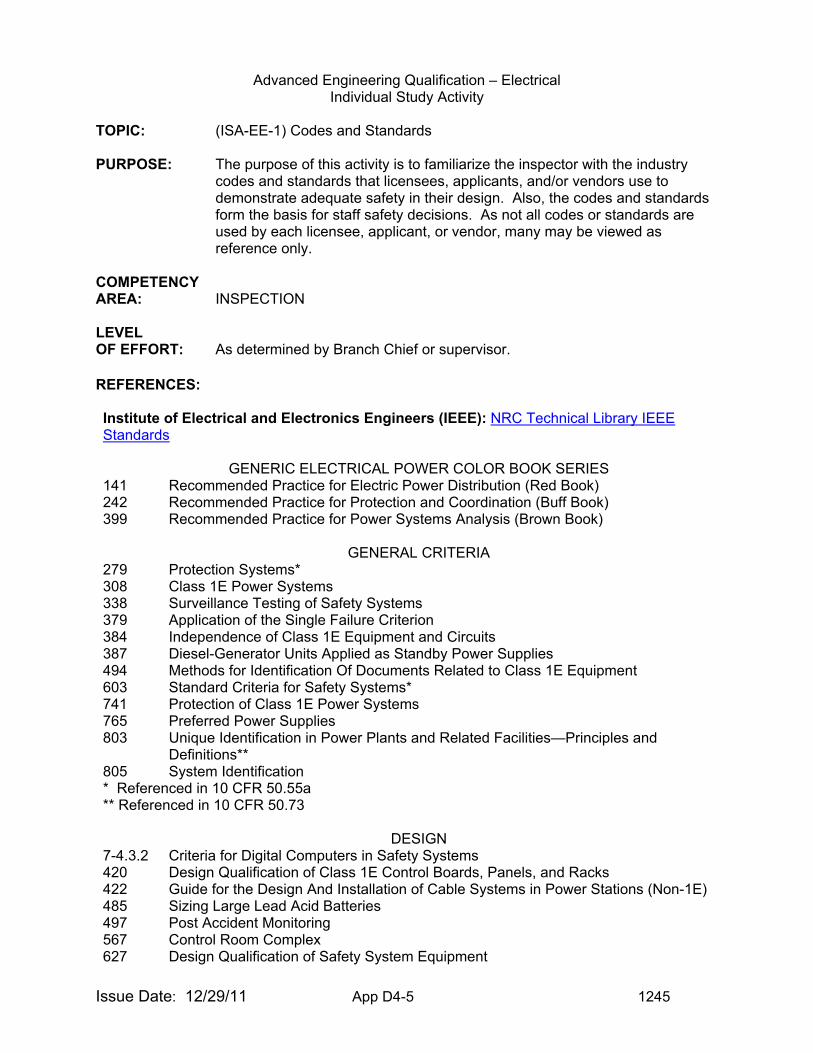
TOPIC: (ISA-EE-1) Codes and Standards PURPOSE: The purpose of this activity is to familiarize the inspector with the industry
codes and standards that licensees, applicants, and/or vendors use to demonstrate adequate safety in their design. Also, the codes and standards form the basis for staff safety decisions. As not all codes or standards are used by each licensee, applicant, or vendor, many may be viewed as reference only.
COMPETENCY AREA: INSPECTION LEVEL OF EFFORT: As determined by Branch Chief or supervisor. REFERENCES:
Institute of Electrical and Electronics Engineers (IEEE): NRC Technical Library IEEE Standards
GENERIC ELECTRICAL POWER COLOR BOOK SERIES
141 Recommended Practice for Electric Power Distribution (Red Book) 242 Recommended Practice for Protection and Coordination (Buff Book) 399 Recommended Practice for Power Systems Analysis (Brown Book)
GENERAL CRITERIA
279 Protection Systems* 308 Class 1E Power Systems 338 Surveillance Testing of Safety Systems 379 Application of the Single Failure Criterion 384 Independence of Class 1E Equipment and Circuits 387 Diesel-Generator Units Applied as Standby Power Supplies 494 Methods for Identification Of Documents Related to Class 1E Equipment 603 Standard Criteria for Safety Systems* 741 Protection of Class 1E Power Systems 765 Preferred Power Supplies 803 Unique Identification in Power Plants and Related Facilities—Principles and
Definitions** 805 System Identification * Referenced in 10 CFR 50.55a ** Referenced in 10 CFR 50.73
DESIGN
7-4.3.2 Criteria for Digital Computers in Safety Systems 420 Design Qualification of Class 1E Control Boards, Panels, and Racks 422 Guide for the Design And Installation of Cable Systems in Power Stations (Non-1E) 485 Sizing Large Lead Acid Batteries 497 Post Accident Monitoring 567 Control Room Complex 627 Design Qualification of Safety System Equipment
Advanced Engineering Qualification – Electrical Individual Study Activity
Issue Date: 12/29/11 App D4-6 1245
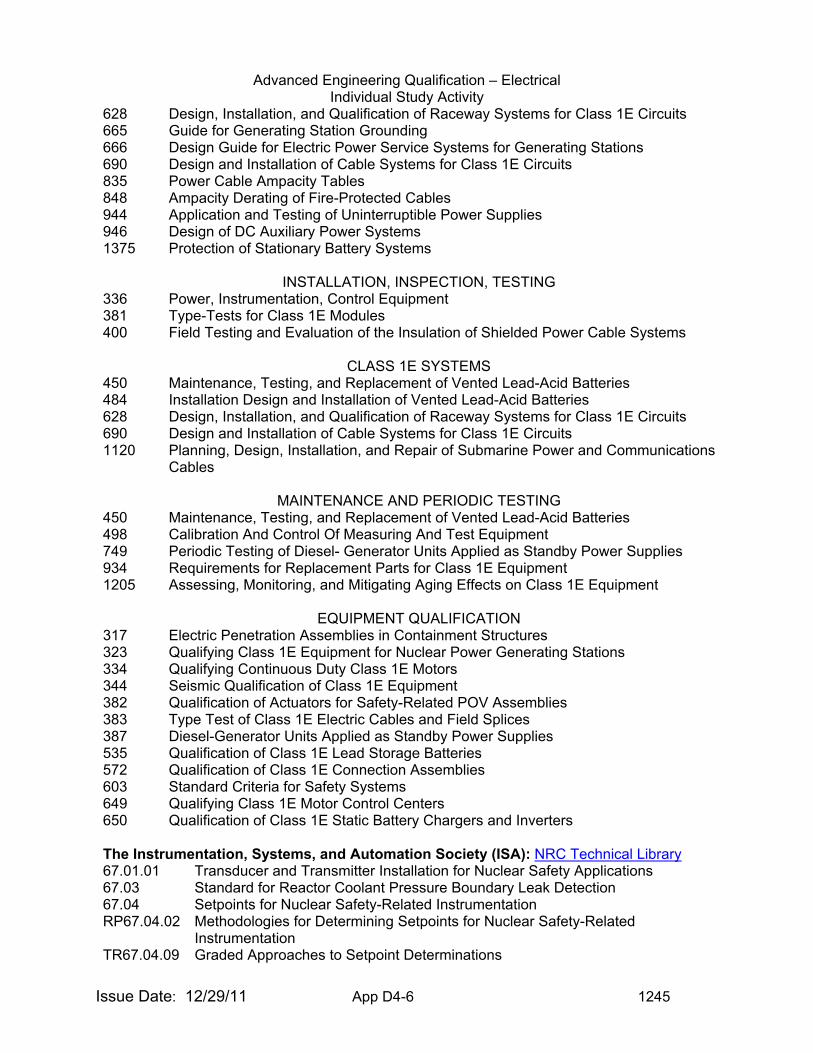
628 Design, Installation, and Qualification of Raceway Systems for Class 1E Circuits 665 Guide for Generating Station Grounding 666 Design Guide for Electric Power Service Systems for Generating Stations 690 Design and Installation of Cable Systems for Class 1E Circuits 835 Power Cable Ampacity Tables 848 Ampacity Derating of Fire-Protected Cables 944 Application and Testing of Uninterruptible Power Supplies 946 Design of DC Auxiliary Power Systems 1375 Protection of Stationary Battery Systems
INSTALLATION, INSPECTION, TESTING
336 Power, Instrumentation, Control Equipment 381 Type-Tests for Class 1E Modules 400 Field Testing and Evaluation of the Insulation of Shielded Power Cable Systems
CLASS 1E SYSTEMS
450 Maintenance, Testing, and Replacement of Vented Lead-Acid Batteries 484 Installation Design and Installation of Vented Lead-Acid Batteries 628 Design, Installation, and Qualification of Raceway Systems for Class 1E Circuits 690 Design and Installation of Cable Systems for Class 1E Circuits 1120 Planning, Design, Installation, and Repair of Submarine Power and Communications
Cables
MAINTENANCE AND PERIODIC TESTING 450 Maintenance, Testing, and Replacement of Vented Lead-Acid Batteries 498 Calibration And Control Of Measuring And Test Equipment 749 Periodic Testing of Diesel- Generator Units Applied as Standby Power Supplies 934 Requirements for Replacement Parts for Class 1E Equipment 1205 Assessing, Monitoring, and Mitigating Aging Effects on Class 1E Equipment
EQUIPMENT QUALIFICATION
317 Electric Penetration Assemblies in Containment Structures 323 Qualifying Class 1E Equipment for Nuclear Power Generating Stations 334 Qualifying Continuous Duty Class 1E Motors 344 Seismic Qualification of Class 1E Equipment 382 Qualification of Actuators for Safety-Related POV Assemblies 383 Type Test of Class 1E Electric Cables and Field Splices 387 Diesel-Generator Units Applied as Standby Power Supplies 535 Qualification of Class 1E Lead Storage Batteries 572 Qualification of Class 1E Connection Assemblies 603 Standard Criteria for Safety Systems 649 Qualifying Class 1E Motor Control Centers 650 Qualification of Class 1E Static Battery Chargers and Inverters
The Instrumentation, Systems, and Automation Society (ISA): NRC Technical Library 67.01.01 Transducer and Transmitter Installation for Nuclear Safety Applications 67.03 Standard for Reactor Coolant Pressure Boundary Leak Detection 67.04 Setpoints for Nuclear Safety-Related Instrumentation RP67.04.02 Methodologies for Determining Setpoints for Nuclear Safety-Related
Instrumentation TR67.04.09 Graded Approaches to Setpoint Determinations
Advanced Engineering Qualification – Electrical Individual Study Activity
Issue Date: 12/29/11 App D4-7 1245
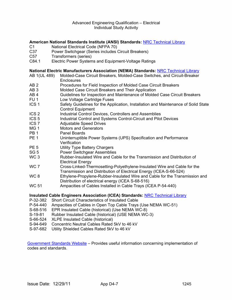
American National Standards Institute (ANSI) Standards: NRC Technical Library C1 National Electrical Code (NFPA 70) C37 Power Switchgear (Series includes Circuit Breakers) C57 Transformers (series) C84.1 Electric Power Systems and Equipment-Voltage Ratings
National Electric Manufacturers Association (NEMA) Standards: NRC Technical Library AB 1(UL 489) Molded-Case Circuit Breakers, Molded-Case Switches, and Circuit-Breaker
Enclosures AB 2 Procedures for Field Inspection of Molded Case Circuit Breakers AB 3 Molded Case Circuit Breakers and Their Application AB 4 Guidelines for Inspection and Maintenance of Molded Case Circuit Breakers FU 1 Low Voltage Cartridge Fuses ICS 1 Safety Guidelines for the Application, Installation and Maintenance of Solid State
Control Equipment ICS 2 Industrial Control Devices, Controllers and Assemblies ICS 5 Industrial Control and Systems Control-Circuit and Pilot Devices ICS 7 Adjustable Speed Drives MG 1 Motors and Generators PB 1 Panel Boards PE 1 Uninterruptible Power Systems (UPS) Specification and Performance
Verification PE 5 Utility Type Battery Chargers SG 5 Power Switchgear Assemblies WC 3 Rubber-Insulated Wire and Cable for the Transmission and Distribution of
Electrical Energy WC 7 Cross-Linked-Thermosetting-Polyethylene-Insulated Wire and Cable for the
Transmission and Distribution of Electrical Energy (ICEA-S-66-524) WC 8 Ethylene-Propylene-Rubber-Insulated Wire and Cable for the Transmission and
Distribution of electrical energy (ICEA S-68-516) WC 51 Ampacities of Cables Installed in Cable Trays (ICEA P-54-440)
Insulated Cable Engineers Association (ICEA) Standards: NRC Technical Library P-32-382 Short Circuit Characteristics of Insulated Cable P-54-440 Ampacities of Cables in Open Top Cable Trays (Use NEMA WC-51) S-68-516 EPR Insulated Cable (historical) (Use NEMA WC-8) S-19-81 Rubber Insulated Cable (historical) (USE NEMA WC-3) S-66-524 XLPE Insulated Cable (historical) S-94-649 Concentric Neutral Cables Rated 5kV to 46 kV S-97-682 Utility Shielded Cables Rated 5kV to 46 kV
Government Standards Website – Provides useful information concerning implementation of codes and standards.
Advanced Engineering Qualification – Electrical Individual Study Activity
Issue Date: 12/29/11 App D4-8 1245
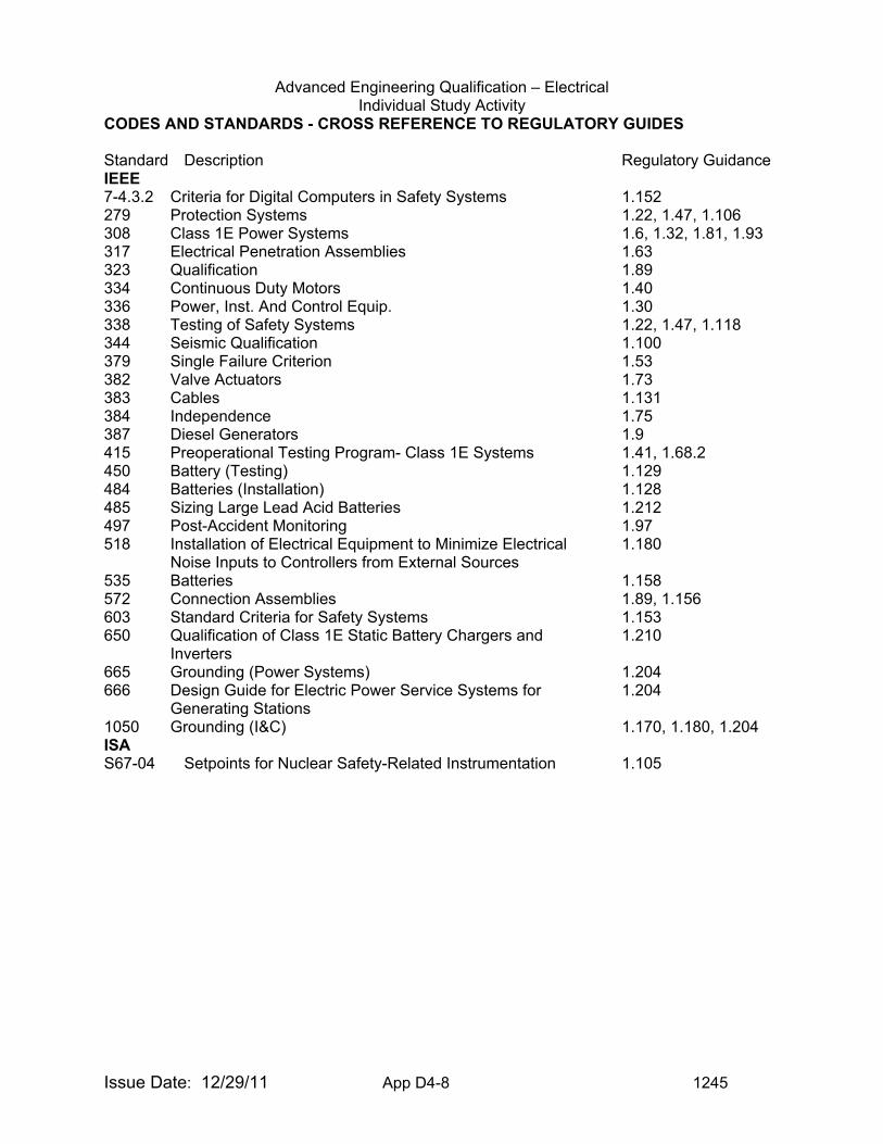
CODES AND STANDARDS - CROSS REFERENCE TO REGULATORY GUIDES Standard Description Regulatory Guidance IEEE 7-4.3.2 Criteria for Digital Computers in Safety Systems 1.152 279 Protection Systems 1.22, 1.47, 1.106 308 Class 1E Power Systems 1.6, 1.32, 1.81, 1.93 317 Electrical Penetration Assemblies 1.63 323 Qualification 1.89 334 Continuous Duty Motors 1.40 336 Power, Inst. And Control Equip. 1.30 338 Testing of Safety Systems 1.22, 1.47, 1.118 344 Seismic Qualification 1.100 379 Single Failure Criterion 1.53 382 Valve Actuators 1.73 383 Cables 1.131 384 Independence 1.75 387 Diesel Generators 1.9 415 Preoperational Testing Program- Class 1E Systems 1.41, 1.68.2 450 Battery (Testing) 1.129 484 Batteries (Installation) 1.128 485 Sizing Large Lead Acid Batteries 1.212 497 Post-Accident Monitoring 1.97 518 Installation of Electrical Equipment to Minimize Electrical
Noise Inputs to Controllers from External Sources 1.180
535 Batteries 1.158 572 Connection Assemblies 1.89, 1.156 603 Standard Criteria for Safety Systems 1.153 650 Qualification of Class 1E Static Battery Chargers and
Inverters 1.210
665 Grounding (Power Systems) 1.204 666 Design Guide for Electric Power Service Systems for
Generating Stations 1.204
1050 Grounding (I&C) 1.170, 1.180, 1.204 ISA S67-04 Setpoints for Nuclear Safety-Related Instrumentation 1.105

Advanced Engineering Qualification – Electrical Individual Study Activity
Issue Date: 12/29/11 App D4-9 1245
NOTE: These references are for general information.
Federal Energy Regulatory Commission (FERC)/North American Electric Reliability Corporation (NERC) Standards Most Important to Nuclear Power Plants
Standard Title Potential benefitNUC-001 Nuclear Plant Interface
Coordination Primary Nuclear Power Plant/Transmission System Interface Standard NUC-001
VAR-001 Voltage and Reactive Control Input to minimum voltages and voltage stabilityTPL-002 System Performance
Following Loss of a Single Bulk Electric System Element
Input to minimum voltages
TPL-003 System Performance Following Loss of Two or More Bulk Electric System Elements
Input to minimum voltages
TOP-002 Normal Operating Planning Correct interpretation of N-1 and N-1-1 for voltage consideration as well as cascading outages. Also input to minimum voltages.
TOP-007 Report System Operating Limits (SOL) and Interregional Reliability Operating Limits (IROL)
Operating one contingency away for cascading for up to 30 minutes.
EOP-005 System Restoration Plans Establish NPP as a priority in power restoration and into to plans that would be verified through simulations and drills.
EOP-008 Plans for Loss of Control Center Functionality
If main control center in not functional, voltage issues are not being monitored. Need to ensure transmission entity has sufficient capability to understand NPP voltages.
BAL-005 Automatic Generation Control Establishes frequency performance of bulk power system.MOD-014 Development of
Interconnection Specific Steady-State System Models
Input to model NPP buses so as to provide for regular screening of NPP operating parameters. Also static and dynamic model validation of voltage and frequency.
MOD-015 Development of Interconnection Specific Dynamic System Models
Input to model NPP buses so as to provide for regular screening of NPP operating parameters. Also static and dynamic model validation of voltage and frequency.
NERC Standards Website

Advanced Engineering Qualification – Electrical Individual Study Activity
Issue Date: 12/29/11 App D4-10 1245
DISCUSSION: A standard may be defined as a document that applies collectively to codes, specifications, recommended practices, test methods, and guides, which have been prepared by a standards developing organization or group, and published in accordance with established procedures. Standards promote safety, reliability, productivity, and efficiency in almost every industry that relies on engineering components or equipment. Standards can run from a few paragraphs to hundreds of pages and are written by experts with knowledge and expertise in a particular field who sit on many committees. Standards are a vehicle of communication for producers and users. They serve as a common language that defines quality and establishes safety criteria. Standards can be further classified as voluntary, consensus, or mandatory. Voluntary standards serve as guidelines but do not of themselves have the force of law. A standards-developing organization (SDO) (e.g., ASME, ANS, IEEE) cannot force any manufacturer, inspector, or installer to follow their standard. The use of a standard is voluntary unless the standard has been incorporated into a business contract or incorporated into regulations. Several industry standards have been classified as mandatory by the NRC for use by licensees and vendors. A code may be defined as a collection of mandatory standards, which has been codified by a governmental authority and become part of the law for the jurisdiction represented by that authority such as the National Electrical Code. The Standards Engineering Society provides further discussion and reference on the definitions, uses and requirements for standards.
Development of a Standard Standards are developed through a voluntary consensus process, written by diverse individuals with the necessary expertise. The consensus process (as defined by American National Standards Institute [ANSI]) means substantial agreement has been reached by directly and materially affected interest groups/parties (e.g., utilities, regulator, academia, research organizations, vendors, consultants, national laboratories). Further, the agreement signifies the concurrence of more than a simple majority, but not necessarily unanimity. Consensus requires that all views and objections be considered, and that an effort be made toward their resolution. Consequently: • The process must reflect openness, transparency, and balance of interest. • The committee meetings addressing technical issues must be open to the public, and
procedures are used to govern deliberations and voting. • The committees must represent a balance of interested parties. • All comments on technical documents during the final approval process must be considered. • Any individual may appeal any action or inaction of a committee relating to membership, or a
code or standard promulgated by the committee. A request for a code or standard may come from individuals, committees, professional organizations, government agencies, industry groups, public interest groups, or from an SDO division or section. The request is first referred to the appropriate supervisory board (e.g., standards board) for consideration. Once the SDO has concluded that there is enough interest and need, the standards development process is initiated.
Advanced Engineering Qualification – Electrical Individual Study Activity
Issue Date: 12/29/11 App D4-11 1245
The general process in developing a standard involves:
• A writing group is formed of technical experts in the associated area. This group reports to the standards committee; it is generally small and does not require a balance of interest among the individuals. This group develops/ writes the draft standard.
• The draft standard is provided to the consensus body or standards committee for ballot.
This committee, which must have a balance of interest, reviews the draft standard and votes (“ballots”) on whether it should be published as written. All committee members must be provided an opportunity to vote on a proposed action; and for the ballot to pass, it must be a majority vote (e.g., for ASME, at least two thirds affirmative vote). In voting, each member of the committee has four options:
1. “Yes” vote with no comments. 2. “Yes” vote with comments – the comments need to be addressed but not
necessarily to the satisfaction of the commenter. 3. “No” vote with comments – the comments need to be addressed to the
satisfaction of the commenter for that commenter to change their negative vote. Further, other members have the opportunity to change their vote based on a negative ballot.
4. “Abstained” (or no-vote).
• The standards committee provides the successfully balloted draft standard to the standards board for ballot. The standards board is performing more of a “procedural” type review to assure that the consensus process was correctly followed. The voting process for the standards board is the same as that for the standards committee. Once the standards board has successfully balloted the draft standard, it goes to ANSI for approval to publish as an American National Standard. However, before requesting ANSI approval, the public is invited to review and comment on the standard. When the public is invited to review and comment varies among the SDOs. For example, ASME public review and comment occurs after the standards board ballots. ANS public review and comment occurs at the same time as the standards committee review and ballot. Comments received from the public are provided to the standards committee and must be reviewed and addressed. The standards committee, however, may not agree with a public comment, but must document the basis for non-agreement.
• A committee member, an individual from the public, or an organization may submit an
“appeal” on a draft standard to the standards committee, standards board, and subsequently, to the Board on Hearings and Appeals. The “appeal” is reviewed and determined whether the appeal has merit:
⇒ If merit is determined, the draft standard is revised and the standard is re-balloted. ⇒ If merit is not determined, the basis is documented and some SDOs require that the
appropriate board determines if the basis is adequate.
• When all considerations have been satisfied, the document is approved as an American National Standard and published by the SDO.
Advanced Engineering Qualification – Electrical Individual Study Activity
Issue Date: 12/29/11 App D4-12 1245
Codes and standards are living documents that are constantly revised to reflect new developments and technical advances (e.g., new materials, new designs, and new applications). Each SDO has defined time intervals for each standard to be reviewed and revised if necessary. NRC Participation and Endorsement Public Law 104-113 (The National Technology Transfer and Advancement Act of 1995), Section 12(d) states that all Federal agencies shall use technical standards that are developed or adopted by voluntary consensus SDOs to carry out their policies and activities, although exceptions are allowed. Office of Management and Budget (OMB) Circular A-119 (Federal Agency Participation in the Development and Use of Voluntary Standards) provides guidelines on implementing Public Law 104-113. OMB Circular A- 119 emphasizes that it is the policy of the Federal government to participate on relevant consensus standard bodies and instruct NRC representatives to express views that are in the public interest and not inconsistent with the interests and established views of NRC. NRC staff generally participates in every aspect in development of a standard by designating a staff as a member of the writing group, standards committee, and standards board. The participating staff provides both its technical expertise and the NRC position on the technical and policy issues associated with the standard. NRC, when relying on a standard, provides its position (or endorsement) in either a regulation or a document that is not a regulation (e.g., regulatory guide, NUREG report). In endorsing a standard, NRC may take exceptions (or objections). These exceptions are consistent with Public Law 104-113 that allows exceptions in order for the NRC to meet its mission, authority, priorities, and budget resources. Examples of Event Reports to Review for Codes and Standards: None. Examples of Findings for Codes and Standards: The failure to follow a standard imposed by regulation or a self-imposed standard is a performance deficiency as defined in Appendix B to Manual Chapter 0612, “Power Reactor Inspection Reports.” As such, most violations associated with not meeting a code or standard are written against non-compliances with the criteria in Appendix B to 10 CFR 50. Examples of Information to Request for Inspection of Codes and Standards:
• Standards to which the licensee may be committed, including appropriate year. (Most Standard establishing bodies (i.e. IEEE) do not maintain long-term archival documents. One example is IEEE Standard 279).
• Any interpretations of the subject standards. Items of Interest to Inspectors for Codes and Standards:
• Commitments by licensee’s to particular standards, and any interpretations they have received.
• Any allowances to deviate from a mandatory standard.
Advanced Engineering Qualification – Electrical Individual Study Activity
Issue Date: 12/29/11 App D4-13 1245
Training associated with Codes and Standards: NFPA Seminars on National Electric Code IEEE Training Website Technical Training Center Electrical/I&C Codes and Standards Course (Pending Development)
Training Lists on Standards.gov
EVALUATION CRITERIA: Upon completion of the tasks in this guide, you will be asked to demonstrate
your understanding of Codes and Standards by performing the following:
Discuss the industry codes and standards with your supervisor in sufficient detail to demonstrate an understanding of their applicability to the areas of design, maintenance, inspection, and qualification of electrical equipment and systems.
TASKS: 1. Read the references in sufficient detail to perform adequately in
accordance with the requirements of the evaluation criteria.
2. Review the Cross-Reference to Regulatory Guides table to gain an understanding of the applicability of the codes and standards to the regulatory guide(s).
3. Meet with your supervisor, or the person designated to be your resource for this activity, and discuss the answers to the question listed under the evaluation criteria.
DOCUMENTATION: Electrical Inspector Advanced-Level Signature Card ISA-EE-1.
Advanced Engineering Qualification – Electrical Individual Study Activity
Issue Date: 12/29/11 App D4-14 1245
TOPIC: (ISA-EE-2) Electrical Design Criteria PURPOSE: The purpose of this activity is to provide the inspector with background
knowledge necessary to understand the design requirements for the offsite and onsite power systems.
COMPETENCY AREA: INSPECTION LEVEL OF EFFORT: As determined by Branch Chief or supervisor REFERENCES:
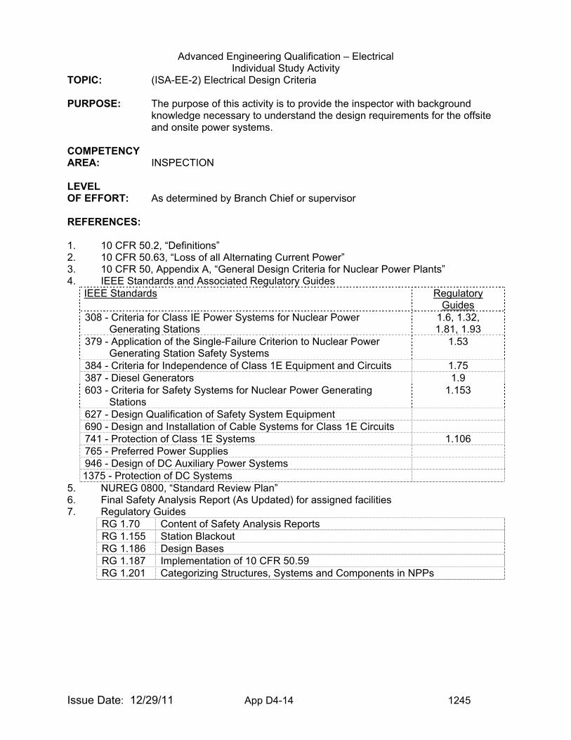
1. 10 CFR 50.2, “Definitions” 2. 10 CFR 50.63, “Loss of all Alternating Current Power” 3. 10 CFR 50, Appendix A, “General Design Criteria for Nuclear Power Plants” 4. IEEE Standards and Associated Regulatory Guides
IEEE Standards
Regulatory Guides
308 - Criteria for Class IE Power Systems for Nuclear Power Generating Stations
1.6, 1.32, 1.81, 1.93
379 - Application of the Single-Failure Criterion to Nuclear Power Generating Station Safety Systems
1.53
384 - Criteria for Independence of Class 1E Equipment and Circuits 1.75 387 - Diesel Generators 1.9 603 - Criteria for Safety Systems for Nuclear Power Generating
Stations 1.153
627 - Design Qualification of Safety System Equipment 690 - Design and Installation of Cable Systems for Class 1E Circuits 741 - Protection of Class 1E Systems 1.106 765 - Preferred Power Supplies 946 - Design of DC Auxiliary Power Systems 1375 - Protection of DC Systems
5. NUREG 0800, “Standard Review Plan” 6. Final Safety Analysis Report (As Updated) for assigned facilities 7. Regulatory Guides
RG 1.70 Content of Safety Analysis Reports RG 1.155 Station Blackout RG 1.186 Design Bases RG 1.187 Implementation of 10 CFR 50.59 RG 1.201 Categorizing Structures, Systems and Components in NPPs
Advanced Engineering Qualification – Electrical Individual Study Activity
Issue Date: 12/29/11 App D4-15 1245
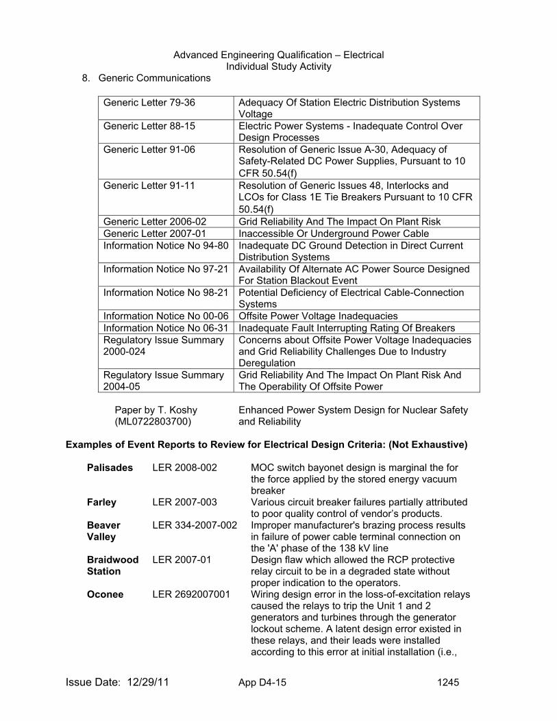
8. Generic Communications Generic Letter 79-36 Adequacy Of Station Electric Distribution Systems
VoltageGeneric Letter 88-15 Electric Power Systems - Inadequate Control Over
Design ProcessesGeneric Letter 91-06 Resolution of Generic Issue A-30, Adequacy of
Safety-Related DC Power Supplies, Pursuant to 10 CFR 50.54(f)
Generic Letter 91-11 Resolution of Generic Issues 48, Interlocks and LCOs for Class 1E Tie Breakers Pursuant to 10 CFR 50.54(f)
Generic Letter 2006-02 Grid Reliability And The Impact On Plant Risk Generic Letter 2007-01 Inaccessible Or Underground Power Cable Information Notice No 94-80 Inadequate DC Ground Detection in Direct Current
Distribution SystemsInformation Notice No 97-21 Availability Of Alternate AC Power Source Designed
For Station Blackout EventInformation Notice No 98-21 Potential Deficiency of Electrical Cable-Connection
SystemsInformation Notice No 00-06 Offsite Power Voltage Inadequacies Information Notice No 06-31 Inadequate Fault Interrupting Rating Of BreakersRegulatory Issue Summary 2000-024
Concerns about Offsite Power Voltage Inadequacies and Grid Reliability Challenges Due to Industry Deregulation
Regulatory Issue Summary 2004-05
Grid Reliability And The Impact On Plant Risk And The Operability Of Offsite Power
Paper by T. Koshy (ML0722803700)
Enhanced Power System Design for Nuclear Safety and Reliability
Examples of Event Reports to Review for Electrical Design Criteria: (Not Exhaustive)
Palisades LER 2008-002 MOC switch bayonet design is marginal the for the force applied by the stored energy vacuum breaker
Farley LER 2007-003 Various circuit breaker failures partially attributed to poor quality control of vendor’s products.
Beaver Valley
LER 334-2007-002 Improper manufacturer's brazing process results in failure of power cable terminal connection on the 'A' phase of the 138 kV line
Braidwood Station
LER 2007-01 Design flaw which allowed the RCP protective relay circuit to be in a degraded state without proper indication to the operators.
Oconee LER 2692007001 Wiring design error in the loss-of-excitation relays caused the relays to trip the Unit 1 and 2 generators and turbines through the generator lockout scheme. A latent design error existed in these relays, and their leads were installed according to this error at initial installation (i.e.,
Advanced Engineering Qualification – Electrical Individual Study Activity
Issue Date: 12/29/11 App D4-16 1245
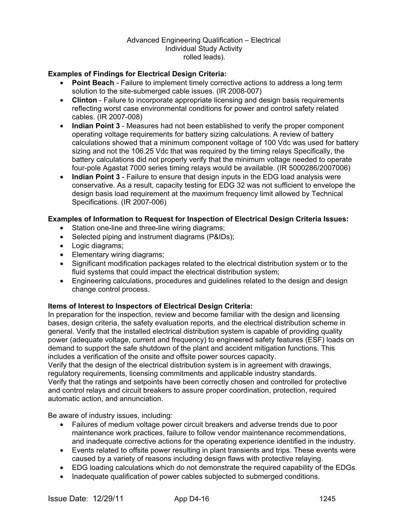
rolled leads). Examples of Findings for Electrical Design Criteria:
• Point Beach - Failure to implement timely corrective actions to address a long term solution to the site-submerged cable issues. (IR 2008-007)
• Clinton - Failure to incorporate appropriate licensing and design basis requirements reflecting worst case environmental conditions for power and control safety related cables. (IR 2007-008)
• Indian Point 3 - Measures had not been established to verify the proper component operating voltage requirements for battery sizing calculations. A review of battery calculations showed that a minimum component voltage of 100 Vdc was used for battery sizing and not the 106.25 Vdc that was required by the timing relays Specifically, the battery calculations did not properly verify that the minimum voltage needed to operate four-pole Agastat 7000 series timing relays would be available. (IR 5000286/2007006)
• Indian Point 3 - Failure to ensure that design inputs in the EDG load analysis were conservative. As a result, capacity testing for EDG 32 was not sufficient to envelope the design basis load requirement at the maximum frequency limit allowed by Technical Specifications. (IR 2007-006)
Examples of Information to Request for Inspection of Electrical Design Criteria Issues:
• Station one-line and three-line wiring diagrams; • Selected piping and instrument diagrams (P&IDs); • Logic diagrams; • Elementary wiring diagrams; • Significant modification packages related to the electrical distribution system or to the
fluid systems that could impact the electrical distribution system; • Engineering calculations, procedures and guidelines related to the design and design
change control process. Items of Interest to Inspectors of Electrical Design Criteria: In preparation for the inspection, review and become familiar with the design and licensing bases, design criteria, the safety evaluation reports, and the electrical distribution scheme in general. Verify that the installed electrical distribution system is capable of providing quality power (adequate voltage, current and frequency) to engineered safety features (ESF) loads on demand to support the safe shutdown of the plant and accident mitigation functions. This includes a verification of the onsite and offsite power sources capacity. Verify that the design of the electrical distribution system is in agreement with drawings, regulatory requirements, licensing commitments and applicable industry standards. Verify that the ratings and setpoints have been correctly chosen and controlled for protective and control relays and circuit breakers to assure proper coordination, protection, required automatic action, and annunciation. Be aware of industry issues, including:
• Failures of medium voltage power circuit breakers and adverse trends due to poor maintenance work practices, failure to follow vendor maintenance recommendations, and inadequate corrective actions for the operating experience identified in the industry.
• Events related to offsite power resulting in plant transients and trips. These events were caused by a variety of reasons including design flaws with protective relaying.
• EDG loading calculations which do not demonstrate the required capability of the EDGs. • Inadequate qualification of power cables subjected to submerged conditions.
Advanced Engineering Qualification – Electrical Individual Study Activity
Issue Date: 12/29/11 App D4-17 1245
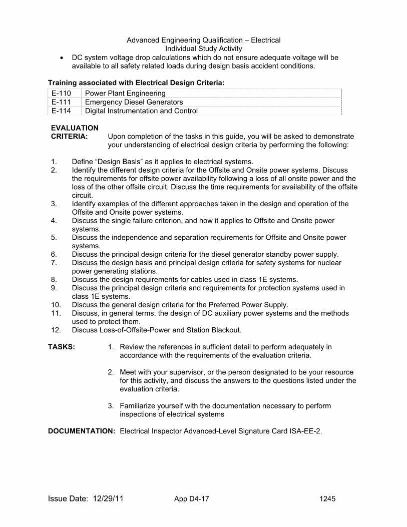
• DC system voltage drop calculations which do not ensure adequate voltage will be available to all safety related loads during design basis accident conditions.
Training associated with Electrical Design Criteria:
EVALUATION CRITERIA: Upon completion of the tasks in this guide, you will be asked to demonstrate
your understanding of electrical design criteria by performing the following: 1. Define “Design Basis” as it applies to electrical systems. 2. Identify the different design criteria for the Offsite and Onsite power systems. Discuss
the requirements for offsite power availability following a loss of all onsite power and the loss of the other offsite circuit. Discuss the time requirements for availability of the offsite circuit.
3. Identify examples of the different approaches taken in the design and operation of the Offsite and Onsite power systems.
4. Discuss the single failure criterion, and how it applies to Offsite and Onsite power systems.
5. Discuss the independence and separation requirements for Offsite and Onsite power systems.
6. Discuss the principal design criteria for the diesel generator standby power supply. 7. Discuss the design basis and principal design criteria for safety systems for nuclear
power generating stations. 8. Discuss the design requirements for cables used in class 1E systems. 9. Discuss the principal design criteria and requirements for protection systems used in
class 1E systems. 10. Discuss the general design criteria for the Preferred Power Supply. 11. Discuss, in general terms, the design of DC auxiliary power systems and the methods
used to protect them. 12. Discuss Loss-of-Offsite-Power and Station Blackout.
TASKS: 1. Review the references in sufficient detail to perform adequately in
accordance with the requirements of the evaluation criteria.
2. Meet with your supervisor, or the person designated to be your resource for this activity, and discuss the answers to the questions listed under the evaluation criteria.
3. Familiarize yourself with the documentation necessary to perform
inspections of electrical systems
DOCUMENTATION: Electrical Inspector Advanced-Level Signature Card ISA-EE-2.
E-110 Power Plant Engineering E-111 Emergency Diesel Generators E-114 Digital Instrumentation and Control
Advanced Engineering Qualification – Electrical Individual Study Activity
Issue Date: 12/29/11 App D4-18 1245
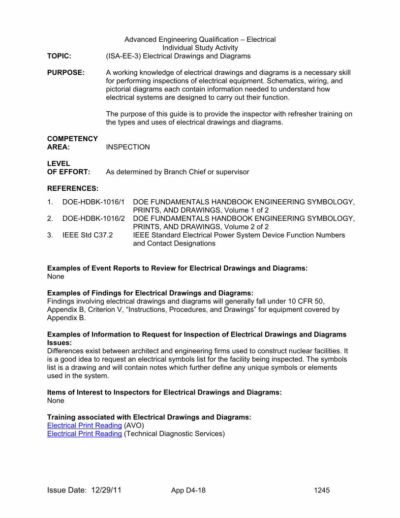
TOPIC: (ISA-EE-3) Electrical Drawings and Diagrams PURPOSE: A working knowledge of electrical drawings and diagrams is a necessary skill
for performing inspections of electrical equipment. Schematics, wiring, and pictorial diagrams each contain information needed to understand how electrical systems are designed to carry out their function.
The purpose of this guide is to provide the inspector with refresher training on the types and uses of electrical drawings and diagrams.
COMPETENCY AREA: INSPECTION LEVEL OF EFFORT: As determined by Branch Chief or supervisor REFERENCES:
Examples of Event Reports to Review for Electrical Drawings and Diagrams: None Examples of Findings for Electrical Drawings and Diagrams: Findings involving electrical drawings and diagrams will generally fall under 10 CFR 50, Appendix B, Criterion V, “Instructions, Procedures, and Drawings” for equipment covered by Appendix B. Examples of Information to Request for Inspection of Electrical Drawings and Diagrams Issues: Differences exist between architect and engineering firms used to construct nuclear facilities. It is a good idea to request an electrical symbols list for the facility being inspected. The symbols list is a drawing and will contain notes which further define any unique symbols or elements used in the system. Items of Interest to Inspectors for Electrical Drawings and Diagrams: None Training associated with Electrical Drawings and Diagrams: Electrical Print Reading (AVO) Electrical Print Reading (Technical Diagnostic Services)
1. DOE-HDBK-1016/1 DOE FUNDAMENTALS HANDBOOK ENGINEERING SYMBOLOGY, PRINTS, AND DRAWINGS, Volume 1 of 2
2. DOE-HDBK-1016/2
DOE FUNDAMENTALS HANDBOOK ENGINEERING SYMBOLOGY, PRINTS, AND DRAWINGS, Volume 2 of 2
3. IEEE Std C37.2 IEEE Standard Electrical Power System Device Function Numbers and Contact Designations
Advanced Engineering Qualification – Electrical Individual Study Activity
Issue Date: 12/29/11 App D4-19 1245
EVALUATION CRITERIA: Upon completion of the tasks in this guide, you will be asked to demonstrate
your understanding of electrical drawings and diagrams by performing the following:
1. Identify the symbols used on electrical drawings for the following components:
a. Single-phase circuit breaker (open/closed) b. Three-phase circuit breaker (open/closed) c. Thermal overload d. Relay e. Potential transformer f. Current transformer g. Single-phase transformer h. Delta-wound transformer i. Wye-wound transformer j. Electric motor k. Meters l. Junctions m. In-line fuses n. Manual Switches o. Limit switches
i. Flow Activated ii. Level Activated iii. Temperature Activated iv. Pressure Activated
p. Generator (wye and delta) q. Diesel-driven generator r. Battery
2. Explain the uses of the following types of electrical drawings:
a. Wiring b. Schematic c. Pictorial
3. Identify the symbols used on electronic block diagrams, prints, and schematics, for the
following components:
a. Fixed resistor b. Variable resistor c. Tapped resistor d. Fixed capacitor e. Variable capacitor f. Fixed inductor g. Variable inductor h. Diode i. Light emitting diode (LED) j. Ammeter k. Voltmeter l. Wattmeter
Advanced Engineering Qualification – Electrical Individual Study Activity
Issue Date: 12/29/11 App D4-20 1245
m. Chassis ground n. Circuit ground o. Silicon controlled rectifier (SCR) p. Half wave rectifier q. Full wave rectifier r. Oscillator s. Potentiometer t. Rheostat u. Amplifier v. PNP and NPN transistors
4. Describe the function for the following Power System Devices:
a. Device number 24 b. Device number 27 c. Device number 32 d. Device number 37 e. Device number 46 f. Device number 47 g. Device number 50 h. Device number 51 i. Device number 52 j. Device number 72 k. Device number 76 l. Device number 86 m. Device number 87
5. Review and discuss the abbreviations associated with Auxiliary devices found on electrical
drawings. TASKS: 1. Review the references in sufficient detail to perform adequately in
accordance with the requirements of the evaluation criteria
2. Meet with your supervisor, or the person designated to be your resource for this activity, and discuss the answers to the questions listed under the evaluation criteria.
3. Familiarize yourself with the documentation necessary to perform
inspections of electrical systems
DOCUMENTATION: Electrical Inspector Advanced-Level Signature Card ISA-EE-3.
Advanced Engineering Qualification – Electrical Individual Study Activity
Issue Date: 12/29/11 App D4-21 1245
TOPIC: (ISA-EE-4) Environmental Qualification of Electric Equipment /Aging PURPOSE: The purpose of this activity is to become familiar with the NRC guidance
documents and regulations governing Environmental Qualification (EQ) of electrical equipment that must function to mitigate the consequences of a loss-of-coolant accident (LOCA) or high energy line break (HELB) and whose environment is adversely affected by that event.
COMPETENCY AREA: INSPECTION LEVEL OF EFFORT: As determined by Branch Chief or supervisor. REFERENCES: 1. 10 CFR 50 Appendix A – GDC 1, 4, and 23 2. 10 CFR 50 Appendix B – Criteria 3 and 11 3. 10 CFR 50.55 a(h) – IEEE 279-1971 4. IEEE 323-1971 and 1974 5. Regulatory Guide 1.89, Revision 1 6. Standard Review Plan Section 3.11 7. DOR Guidelines, November 1979 8. NUREG 0588 (for comment version), December 1979 9. IEB 79-01B, January 14, 1980 10. NRC Memorandum and Order CLI-80-21, May 23, 1980 11. 10 CFR 50.49 Environmental qualification of electric equipment important to safety for
nuclear power plants (the EQ Rule, Published January 21, 1983, Effective February 23, 1983)
DISCUSSION: Safety-related electrical equipment must be capable of performing design safety functions under all normal, abnormal, and accident conditions. The purpose of equipment qualification is to provide tangible evidence that equipment will operate on demand and to verify design performance, thereby establishing assurance that the potential for common-mode failure is minimized. Of particular concern is the assurance that equipment will remain operable during and following exposure to the harsh environmental conditions (i.e., temperature, pressure, humidity [steam], chemical sprays, radiation, and submergence) imposed as a result of a design basis accident. These harsh environments are generally defined by the limiting conditions resulting from the complete spectrum of postulated break sizes, break locations, and single failures consequent to a LOCA, main steam line break (MSLB) inside the reactor containment, or a high energy line break (HELB) outside the reactor containment (such as main steam or feedwater line break). In addition, depending on specific plant design features, other postulated HELB locations may be associated with:
• steam generator blowdown • the chemical and volume control system (CVCS) letdown line • the steam supply piping to
- auxiliary feedwater (AFW) pump turbine - reactor core isolation cooling (RCIC) pump turbine
Advanced Engineering Qualification – Electrical Individual Study Activity
Issue Date: 12/29/11 App D4-22 1245
- high pressure core injection (HPCI) pump turbine - isolation condenser - auxiliary boiler HISTORY OF EQUIPMENT QUALIFICATION (EQ):
• November 4, 1977, the Union of Concerned Scientists petitioned the NRC Commissioners to upgrade current standards for the EQ of safety-related electrical equipment in operating plants.
• December 1977, NRC issues a Generic Letter to all Systematic Evaluation Program
(SEP) plant licensees requesting that they initiate reviews to determine the adequacy of existing equipment qualification documentation.
• May 31, 1978, NRC issued IE Circular (IEC) 78-08, “Environmental Qualification of
Safety-Related Electrical Equipment at Nuclear Power Plants, “requiring all licensees of operating plants (except those included in the SEP) to examine their installed safety-related electrical equipment and ensure appropriate qualification documentation for equipment function under postulated accident conditions.
• February 8, 1979, NRC issued IE Bulletin 79-01, which was intended to raise the
threshold of IEC 78-08 to a Bulletin requiring a response. This Bulletin required a complete re-review of the EQ of safety-related electrical equipment as described in IEC 78-08.
• Second half of 1979, the Division of Operating Reactors (DOR) of the NRC issued
internally a document entitled, “Guidelines for Evaluating Environmental Qualification of Class 1E Electrical Equipment in Operating Reactors.”
• January 14, 1980, NRC issued IE Bulletin 79-01B and the DOR Guidelines as
Enclosure 4 to the bulletin. This bulletin expanded the scope of IE Bulletin 79-01 and requested additional information on EQ of safety-related electrical equipment. The Bulletin stated that the staff would review the licensee’s submittals using the criteria contained in the DOR Guidelines; NUREG 0588 would be used as a guide in cases where the DOR Guidelines do not provide sufficient detail.
• May 23, 1980, the NRC Commission by its Memorandum and Order CLI-80-21, directed
the staff to proceed with a rulemaking on environmental qualification of safety-related equipment and to address the question of backfit. The commission also directed that
the DOR Guidelines and NUREG-0588 form the basis for the requirements licensees and applicants must meet until the rulemaking has been completed.
• January 7, 1982, the NRC Commissioners approved the issuance of the proposed EQ
rule.
• January 20, 1982, the proposed EQ rule was published in the Federal Register (Volume 45, No. 13)
• January 21, 1983, the final EQ rule was published in the Federal Register (FR) (Volume
48, No.15, Pages 2729 thru 2734) and became effective February 22, 1983.
Advanced Engineering Qualification – Electrical Individual Study Activity
Issue Date: 12/29/11 App D4-23 1245
ELECTRICAL EQUIPMENT COVERED BY THE EQ RULE The rule specifies that the following electrical equipment must be qualified: (a) Safety-related electric equipment which is located in a LOCA and/or a HELB environment and is relied upon to remain functional during and following design basis events. (b) Non safety-related electric equipment whose failure under accident conditions could prevent satisfactory accomplishment of safety functions. (c) Certain post-accident monitoring equipment addressed in Regulatory Guide 1.97, “Instrumentation For Light-Water-Cooled Nuclear Power Plants To Assess Plant And Environs Conditions During And Following An Accident.” OTHER PROVISIONS OF THE EQ RULE The rule: (a) Requires development of a list of EQ equipment and EQ files. (b) Identifies factors to be considered in establishing qualification of equipment: (1) Temperature and pressure (2) Humidity (3) Chemical effects (4) Radiation (5) Aging (6) Submergence (7) Synergistic effects (8) Margins (c) Provides methods to establish qualification for EQ equipment (1) Testing an identical item (2) Testing a similar item with a supporting analysis (3) Past experience with identical or similar equipment (4) Analysis in combination with partial type test data (d) Requires that EQ records must be maintained in an auditable form for the entire period during which the covered item is installed in the nuclear plant. (e) States that items which were previously qualified to the DOR Guidelines or NUREG 0588 need not be re-qualified to the rule. (f) Requires that replacement equipment must be qualified to the rule unless there are sound reasons to the contrary as outlined in Regulatory Guide 1.89, “Environmental Qualification of Certain Electric Equipment Important to Safety for Nuclear Power Plants.” WHAT THE EQ RULE DID NOT DO
Advanced Engineering Qualification – Electrical Individual Study Activity
Issue Date: 12/29/11 App D4-24 1245
The rule: (a) Did not address seismic and dynamic qualification of electric equipment. (b) Did not address protection of electric equipment important to safety against other natural phenomena and external events. (c) Did not address environmental qualification of electric equipment important to safety located in a mild environment. LICENSING REQUIREMENTS FOR EQ (GENERAL)
• For all operating reactors licensed prior to May 23, 1980, the original EQ equipment was in general evaluated for qualification against the DOR Guidelines.
• For all plants licensed after May 23, 1980, the original EQ equipment was required to
conform to NUREG 0588 as follows: (1) If the plant construction permit (CP) safety evaluation report (SER) was dated before July 1, 1974 – the licensee must meet Category II requirements of NUREG – 0588 (IEEE 323-1971). (2) If the plant CP SER was dated on or after July 1, 1974 – the licensee must meet Category I requirements of NUREG – 0588 (IEEE 323-1974).
• Replacement equipment installed subsequent to February 22, 1983 must be qualified to the 50.49 rule unless there are sound reasons to the contrary. [For examples of sound reasons deemed acceptable by the staff see Regulatory Guide 1.89, Rev. 1.]
Examples of Event Reports to Review for Environmental Qualification: None
Examples of Findings for Environmental Qualification: 1. Unqualified tape splices
The licensee failed to demonstrate qualification for tape splices used on numerous EQ components and systems.
2. Cable inside containment The licensee failed to demonstrate qualification for cables inside containment.
3. Connectors and heat shrink sleeves on Crouss-Hinds penetrations The licensee did not have qualification documentation in their EQ file demonstrating qualification for the connectors and heat shrink splices on the penetrations.
4. Various deficiencies in Limitorque MOVs (a) Unqualified grease used in limit switch and main gear compartments (b) T-drains and grease relief valves missing and/or painted over (c) Motor leads had unqualified taped splices (d) Terminal blocks unidentified and/or unqualified (e) Unqualified motor brakes (f) Limit switch with an aluminum housing used inside containment (g) Mixed greases (h) Unidentified and/or unqualified jumper wires (i) Nylon connectors in dual voltage motors 5. Cable entrance seals (Moisture intrusion seals) The licensee failed to install cable entrance seals on EQ equipment that was qualified with a seal. Examples included: (a) Rosemount 1153A transmitters
Advanced Engineering Qualification – Electrical Individual Study Activity
Issue Date: 12/29/11 App D4-25 1245
(b) Target Rock solenoid valves (c) ASCO solenoid valves (d) NAMCO limit switches 6. Instrument Accuracies
The EQ files did not specify required accuracies and compare them with instrument loop errors based on LOCA type tests.
7. Terminal blocks (TBs) The licensee failed to establish qualification for use of TBs in instrument circuits inside containment. Insulation resistance values will not provide the required instrument accuracy.
8. Unqualified moisture intrusion seals Raychem/CHICO A seal not environmentally tested for use inside containment or main steam valve rooms. 9. GEMS level transmitters Licensee failed to install the transmitters in accordance with the tested configuration.
- No silicone oil - Unqualified tape splice
10. Various deficiencies with skid mounted components that were not EQ (a) Speed sensors (b) Float switches (c) Control relays (d) Jumper wires 11. Resistance temperature detectors (Model RdF)
Licensee failed to install the RTDs in accordance with the tested configuration. The bellows assembly which insulated the RTD pigtail lead wires from moisture ingress was removed during installation.
12. Victoreen high range radiation monitor Detector not installed in accordance with the tested configuration. For Operating Experience on recent EQ issues go to the NRR web address http://nrr10.nrc.gov/ope-info-gateway/index.html and select @OperatingExperienceCommunity, Materials/Aging to find the following reports: 1. Peach Bottom – Hardened Grease on Valves Causes HPCI to be Declared Inoperable 2. Diablo Canyon (1, 2) – Inadequate ASCO Valve Qualification Causes Plant Trip 3. ANO U1 – Failure to Promptly Correct Degraded Containment Isolation Valves 4. Magnesium Rotor Failures and Inspection Methods 5. Watts Bar Special Report on Thermal Induced Currents 6. Indian Point – 3 dropped rod and shutdown due to cable splice issues Examples of Information to Request for Inspection of Environmental Qualification Issues: The inspectors should review EQ inspection guidance:
• TI 2515/76 EQ Program (ML090980422) • TI 2515/75 Limitorque Wiring (ML090980420) • TI 2500/17 Raychem Splices (ML090980410)
Identify appropriate inspection objectives:
• Review of licensee’s implementation of a program for meeting 10 CFR 50.49 requirements.
• Review of licensee’s implementation of SER corrective action commitments.
Advanced Engineering Qualification – Electrical Individual Study Activity
Issue Date: 12/29/11 App D4-26 1245
• Review of licensee’s implementation of a program for maintaining the qualified status of equipment during the life of the plant.
• Perform physical inspection of equipment to determine that the installations agree with SER commitments and qualification requirements.
Define scope of inspection:
• Procedural and programmatic review • EQ maintenance • Operating Experience (e.g., handling of NRC Notices and Bulletins) • EQ master list • Walkdown of EQ equipment • Cable identification • EQ equipment replacement and spare parts procurement • EQ modification program • EQ personnel training • SER commitments • Regulatory Guide 1.97 • Heat shrinkable tubing • Limitorque internal wiring
During inspection preparation the inspector should review the licensee’s:
• EQ organization • EQ procedures • EQ file arrangement • EQ Profiles for LOCA and HELB accident environments
The primary role of equipment qualification is to ensure that electrical equipment important to safety can perform its safety function(s) with no failure mechanism that could lead to common cause failures under postulated service conditions. It is degradation with time (aging), followed by exposure to the environmental extremes of temperature, pressure, humidity, radiation, vibration, or chemical spray resulting from design basis events which presents a potential for causing common cause failures of EQ equipment. For this reason, a qualified life should be established for equipment with significant aging mechanisms unless aging is adequately addressed by periodic surveillance and maintenance. The methods used in establishing a qualified life should be based on type testing, operating experience, analysis, or any combination thereof. For (non-EQ) safety-related equipment located in mild environments and which has no significant aging mechanisms, a qualified life is not required. This equipment shall be selected for application to the specific service conditions based on sound engineering practices and manufacturer’s recommendations. A thorough understanding of equipment design, construction, operation, and functions is required for a comprehensive aging evaluation. Available equipment information, including manufacturer’s drawings, material lists, engineering specifications, and other technical data should be reviewed. Some specific information on the aging and qualification practices for cable splices used in nuclear power plants is provided in NUREG/CR-6788 (ML0228904080).
Advanced Engineering Qualification – Electrical Individual Study Activity
Issue Date: 12/29/11 App D4-27 1245
Items of Interest to Inspectors for Environmental Qualification: There have been numerous NRC Bulletins, Circulars, and Information Notices issued on EQ of safety-related equipment over the years. The inspector should be familiar with the subject matter of some of the key notices dealing with EQ of components. Below is a summary of some of the key notices covering various types of EQ electrical equipment important to safety. Circulars 78-08 EQ of Safety-Related Electrical Equipment (General) Connectors, Penetrations, Terminal blocks, Limit Switches, Cable Splices 79-05 Moisture leakage in Stranded Wire Connectors 80-10 Failure to Maintain EQ of Equipment Bulletins 77-05A Electrical Connector Assemblies (Bendix, ITT Cannon and Gulton Industries) 78-02 Terminal Block Qualification (Marathon M-6012) 78-04 EQ of Certain Stem Mounted Limit Switches Inside Reactor Compartment. (NAMCO) 78-14 Deterioration of BUNA-N Components in ASCO Solenoids 79-28 Possible Malfunction of NAMCO Model EA180 Limit Switches at Elevated Temperatures 82-40 Deficiencies in Primary Containment Electrical Penetration Assemblies Information Notices 79-03 Limitorque Valve Geared Limit Switch Lubricant 79-22 HELB Concerns 82-03 EQ of Electrical Terminal Blocks 82-11 Potential Inaccuracies in Wide Range Pressure Inst. Used in Westinghouse Designed Plants 82-52 EQ Testing Experience – Updating of Test Summaries Previously Published in IN 81-29 83-40 Need to Environmentally Qualify Epoxy Grouts and Sealers 83-45 EQ Test of GE “CR-2940” Position Selector Control Switch 83-72 EQ Testing Experience 84-23 Results of the NRC Sponsored Qual Methodology Research Test on ASCO Solenoid Valves 84-44 EQ Testing of Rockbestos Cables 84-47 EQ Testing of Electrical Terminal Blocks 84-57 Operating Experience Related to Moisture Intrusion in S/R Electrical Equipment 84-68 Potential Deficiency in Improperly Rated Field Wiring to Solenoid Valves 84-78 Underrated Terminal Blocks that may Adversely Affect Operation of Essential Electrical Equipment 84-90 Main Steam Line Break Effect on EQ Equipment 85-08 Industry Experience on Certain Material Used in S/R Equipment 85-17 Possible Sticking of ASCO Solenoid Valves 85-39 Auditability of Electrical Equipment Qualification Records at Licensee’s Facilities 85-40 Deficiencies in EQ Testing and Certification Process 85-47 Potential Effect of Line-Induced Vibration on Certain Target Rock Solenoid Operated Valves 85-100 Rosemount D/P Transmitter Zero Point Shift 86-02 Failure of Valve Operator Motor During EQ Testing 86-03 Potential Deficiencies of Limitorque Motor Valve Operator Wiring
Advanced Engineering Qualification – Electrical Individual Study Activity
Issue Date: 12/29/11 App D4-28 1245
86-53 Improper Installation of Heat Shrinkable Tubing (Raychem) 86-65 Malfunctions of ITT Barton Model 580 Series Switches During Requalification Testing 86-71 Limitorque – Burnt wire caused by Heater Element and Cracking of White Melamine Limit Switch Rotors 86-104 Unqualified Butt Splice Connector Identified in Qualified Penetrations 87-08 Degraded Motor Leads in Limitorque DC Motor Operators 87-66 Inappropriate Application of Commercial Grade Components 97-45 Supplement 1: EQ Deficiency for Cables And Containment Penetration Pigtails 06-14 Supplement 1: Potentially Defective External Lead-Wire Connections in Barton Pressure Transmitters 06-26 Failure of Rotors in Motor Operated Valve Actuators Training associated with Environmental Qualification: EQ Training (128 min. video) conducted by Tom Koshy from the Office of Research, discusses the regulatory requirements of 10 CFR 50.49, associated guidance, and inspection procedures. The two part video is on the Region II Website: http://r2.nrc.gov/videoarchive/viewvideo.cfm?vlink=56 http://r2.nrc.gov/videoarchive/viewvideo.cfm?vlink=57 EVALUATION CRITERIA: Upon completion of the tasks in this guide, you will be asked to demonstrate
your understanding of Environmental Qualification by performing the following:
1. Describe the categories of electrical equipment that are required to be qualified in
accordance with 10 CFR 50.49. 2. Describe the factors to be considered in establishing qualification of electrical
equipment. 3. Describe what lists, records or documents must be maintained and available for NRC
audit. 4. Describe the methods that are acceptable for establishing qualification for EQ
equipment. 5. Describe what is meant by qualified life of an EQ component. 6. Describe what a licensee’s current licensing basis is for EQ. 7. Describe the licensing requirements for replacement equipment. 8. Describe the difference between a harsh environment and a mild environment for safety-
related equipment. TASKS: 1. Read the references in sufficient detail to perform adequately in
accordance with the requirements of the evaluation criteria. 2. Meet with your supervisor, or the person designated to be your resource
for this activity, and discuss the answers to the questions listed under the evaluation criteria.
3. Familiarize yourself with the inspection resources listed under the Operational Experience website.
4. Familiarize yourself with the documentation necessary to perform inspections of EQ.
DOCUMENTATION: Electrical Inspector Advanced-Level Signature Card ISA-EE-4.
Advanced Engineering Qualification – Electrical Individual Study Activity
Issue Date: 12/29/11 App D4-29 1245
TOPIC: (ISA-EE-5) Containment Electric Penetrations PURPOSE: Electrical penetration assemblies provide electrical continuity for field cables
penetrating containment and maintain containment integrity. Degraded electrical penetration assemblies can adversely affect containment integrity by allowing excessive leakage from the containment under accident conditions. The purpose of this guide is to provide the inspector with information and references useful for the inspection of electrical penetrations in containment structures.
COMPETENCY AREA: INSPECTION LEVEL OF EFFORT: To be determined by Branch Chief or supervisor. REFERENCES:
1. 10 CFR 50, Appendix A, General Design Criteria 18 and 50 2. IEEE Std 317 Electric Penetration Assemblies in Containment Structures for Nuclear
Power Generating Stations 3. IEEE Std 338 Standard Criteria for the Periodic Surveillance Testing of Nuclear Power
Generating Station Safety Systems 4. IEEE Std 741 Standard Criteria for the Protection of Class 1E Power Systems and
Equipment in Nuclear Power Generating Stations 5. RG 1.63
Electric Penetration Assemblies In Containment Structures For Nuclear Power Plants
6. RG 1.118 Periodic Testing of Electric Power and Protection Systems
Examples of Event Reports to Review for Electric Penetrations: 94081
Portland General Electric, Parker Packing Inappropriate Or Degraded Seals In Containment Electrical Penetration Assemblies
12/22/1993 9401060376
91071 Portland General Electric, Bunker Ramo, Parker Packing Containment Pressure Boundary Capability Of Electrical Penetration Assembly Module Polyurethane Seals
06/24/1991 9106270260
89135
Houston Lighting And Power Containment Electrical Penetrations Not Provided With Backup Overcurrent Protection
02/22/1989 8903030466
85374
Union Electric, Bechtel Power Overcurrent Protection Of Containment Penetrations
04/22/1985 8505020444
Advanced Engineering Qualification – Electrical Individual Study Activity
Issue Date: 12/29/11 App D4-30 1245
Examples of Findings for Electric Penetrations: • Failure To Maintain Containment Electrical Penetration Enclosures
The inspectors identified a non-cited violation of 10 CFR 50 Appendix B, Criterion XVI for failure to identify a condition adverse to quality in that East and West Penetration Room containment electrical penetration enclosures had not been maintained, such that a number of enclosures allowed the introduction of dirt and debris inconsistent with conditions under which these penetrations were environmentally qualified.
• Failure to Develop and Implement a Cleanliness Inspection Program for the Containment Electrical Penetrations A NRC-identified non-cited violation of 10 CFR 50 Appendix B, Criterion X, Inspection, was identified for the failure to develop and implement an inspection program for inspection and cleaning of the containment electrical penetrations located in the East and West Penetration Rooms of Units 1, 2, and 3. The finding was considered to be a performance deficiency in that the licensee had failed to develop an inspection program for their containment electrical penetrations to ensure cleanliness of the electrical connections. The inspectors concluded that if left uncorrected (no inspection) debris and rust accumulation could lead to failure of the electrical circuits during a high energy line break as a result of grounds and shorts.
Examples of Information to Request for Inspection of Electric Penetrations Issues: Containment electrical penetrations are considered part of the cabling system in which they are used. As such, the protective devices for the system or component fed by the cabling are subject to inspection as part of the cable penetration. Molded case circuit breakers and fuses are frequently used as the protective devices.
• Drawings showing penetration composition and orientation • Electrical drawings for the penetration • Previous testing (surveillance, post-maintenance, etc…) results for protective devices
used in the system • Previous leakage testing results for the penetration
Items of Interest to Inspectors for Electric Penetrations: Information Notice No. 82-40 Deficiencies In Primary Containment Electrical Penetration
Assemblies Information Notice No. 88-89 Degradation Of Kapton Electrical Insulation Information Notice No. 93-25 Electrical Penetration Assembly Degradation Information Notice No. 97-45 Supp1
Environmental Qualification Deficiency For Cables And Containment Penetration Pigtails
Operating Experience On January 11, 2005, a licensee noted that the existing Containment Building CEDM Cooling Fan Dampers indication circuits (120 VAC), which feeds through electrical penetrations, did not have a secondary fuse. Additionally, they found its feeder breaker was not included in their testing program for penetration breakers. Subsequently, on January 25, 2005 while performing follow-up activities for the above mentioned issues, the licensee identified additional 120 VAC circuits with similar deficiencies as noted above, as well finding additional deficiencies with two 480 V circuits that provide power for the controls associated with the outlet of the Safety Injection Tank. Specifically, the backup protective devices for the two 480V circuits were miss-sized for the feed-through conductors. Documentation was reviewed for circuits associated with the problem, with a focus on those circuits which are most likely to be at risk of being deficient. In this review, the licensee ensured that the circuits to the interrupting devices were sized properly for the current that they carry.
Advanced Engineering Qualification – Electrical Individual Study Activity
Issue Date: 12/29/11 App D4-31 1245
Additionally, the specific circuit breakers have been added to the licensee’s Penetration Breaker Surveillance Testing Procedure. Training associated with Electric Penetrations: None. EVALUATION CRITERIA: Upon completion of the tasks in this guide, you will be asked to demonstrate
your understanding of Electric Penetrations by performing the following: 1. Discuss the impact of GDC 18 and 50 on containment electrical penetrations. 2. Discuss the scope of IEEE Standard 338 as it relates to electric penetration assemblies
in containment structures. 3. Discuss the service classifications for electric penetration assemblies and the ratings
associated with each. 4. Identify the standard used to test the mechanical integrity of electric penetration seals. 5. Discuss the leak rate testing requirements of electric penetration assemblies installed in
containment structures. 6. Familiarize yourself with Annex C to IEEE Standard 338. Discuss the different
configurations of penetration assemblies. 7. Discuss the requirements for periodic surveillance of containment electric penetrations. 8. Review section 5.4 of IEEE Standard 741-1986. Discuss the requirements for special
consideration penetrations.
TASKS: 1. Read the references in sufficient detail to perform adequately in accordance with the requirements of the evaluation criteria.
2. Meet with your supervisor, or the person designated to be your resource for this activity, and discuss the answers to the questions listed under the evaluation criteria.
3. Familiarize yourself with the inspection resources listed under the Operational Experience website.
4. Familiarize yourself with the documentation necessary to perform inspections of containment electric penetration assemblies.
DOCUMENTATION: Electrical Inspector Advanced-Level Signature Card ISA-EE-5.
Advanced Engineering Qualification – Electrical Individual Study Activity
Issue Date: 12/29/11 App D4-32 1245
TOPIC: (ISA-EE-6) AC Analysis for Power Systems PURPOSE: The purpose of this guide is to acquaint the reader with the various
calculations and studies that are performed to support the design and operation of the Electrical Distribution System at nuclear power plants. It also introduces various design considerations to ensure adequate voltage in an auxiliary electric distribution system.
COMPETENCY AREA: INSPECTION LEVEL OF EFFORT: As determined by Branch Chief or supervisor.
REFERENCES: 1. IEEE Std. 141 IEEE Recommended Practice for Electric Power Distribution for
Industrial Plants 2. IEEE Std. 242 IEEE Recommended Practice for Protection and Coordination of
Industrial and Commercial Power Systems 3. IEEE Std. 399 IEEE Recommended Practice for Industrial and Commercial Power
Systems Analysis 4. IEEE Std. 741 IEEE Standard Criteria for the Protection of Class 1E Power Systems
and Equipment in Nuclear Power and Generating Stations 5. ML092190254 White Paper, “Adequacy of Nuclear Station Electrical Distribution
System Voltages” by P. J. Fillion 6. ML092190854 IEEE paper, “Design of AC Auxiliary Power Distribution Systems For
Large TVA Thermal Power Generating Plants” by G. R. Reed and D. R. Webster, 1975
7. ML092190747 IEEE paper, “An Auxiliary Power System For A 500 to 600 MW Coal Power Plant” by R. M. Damar and J. P. Henschel, 1981
8. IEEE Std 666 IEEE Design Guide for Electric Power Service Systems for Generating Stations
9. IEEE paper, “Selection of Setpoint for the Degraded Voltage Relays at Commercial Nuclear Power plants” by R. K. Das and A. Julka, 1993
10. IEEE paper, “A discussion of Degraded Voltage Relaying for Nuclear Generating Stations” by G. L. Nicely, N. Trehan, G. Attarian, et. al, 1998
DISCUSSION: The basic design problem of a power plant auxiliary distribution system (or similar system) is achieving the optimum balance between providing adequate voltage to all electric components and limiting the short-circuit current to levels within the interrupting rating of the circuit breakers. References 6 and 7 provide an excellent discussion of the problem and its solution. Each distribution and utilization equipment has an associated set of voltage limits for good operation. Motors, for example, have a rated voltage range for continuous operation, a stall voltage, a starting voltage and a short-time voltage. In addition, these voltage limits are not independent of frequency. There is a set of limits when frequency is nominal, an acceptable range of frequency when voltage is nominal, and an acceptable operating region when voltage and frequency vary together. Sometimes the limit is expressed in terms of volts per hertz. Reference 8, Chapters 5 and 11, is an excellent source of information on voltage limits and on
Advanced Engineering Qualification – Electrical Individual Study Activity
Issue Date: 12/29/11 App D4-33 1245
the effects of variations of magnitude and frequency from the optimum values. An AC 460 V motor has an acceptable range of voltage for continuous operation of 414 – 506 V, and insulation rated for 600 V. One question that is asked from time to time is: “What is the problem with energizing that motor with a voltage that is above 506 V – but below 600 V? The answer is that magnetic flux in the core of the motor creates heat losses and these losses are proportional to the applied volts per hertz. So energizing with say 550 V at 60 hertz would cause excessive heating of the motor’s magnetic core. Also, be aware that voltage imbalance between phases can jeopardize motor performance. Voltage imbalance is defined by the National Electric Manufacturer’s Association (NEMA) as the maximum voltage deviation from the average of the three phases divided by the average three phase value. The reason for this is that unbalanced voltages create negative sequence voltages which result in negative sequence currents. Even relatively low levels of negative sequence current result in a significant increase in rotor temperature as compared to the balanced condition. A number of nuclear power plants have offsite power transformers equipped with an automatic on-load tap changer. The real purpose of the automatic on-load tap changer is to relax the constraints placed on the allowable range of voltages at the plant switchyard. In theory, a plant auxiliary distribution system supplied by a transformer with automatic on-load tap changing capability could tolerate such a wide variation in switchyard voltage that it would be virtually immune to degraded voltage (obviously it would not be immune to loss of voltage). However, these systems are not as reliable as a system with a fixed ratio transformer simply due to the complexity of the on-load tap changer mechanism and attendant control circuitry. In light of this consideration, many plants with the automatic on-load tap changer still analyze their system like it had a fixed ratio transformer. This analysis would allow continued operation should the automatic function become inoperable. In this case, the automatic function would be disabled and the tap changer would be manually placed on the tap dictated by the analysis. Keep in mind too that voltage calculations for a system with a functioning automatic on-load tap changer and with accident loads energized in a series of sequenced load blocks would be quite complex. The complexity of modern industrial power systems makes studies difficult, tedious, and time-consuming to perform manually. The computational tasks associated with power systems studies have been greatly simplified by the use of digital computer programs. User-friendly programs utilizing interactive menus, online help facilities, and a graphical user interface guide the engineer through the task of using a digital computer program. The engineer in charge of system design must decide which studies are needed to ensure that the system will operate safely, economically, and efficiently over the expected life of the system. In the design stage, the studies identify and avoid potential deficiencies in the system before it goes into operation. In existing systems, the studies help locate the cause of equipment failure and mis-operation, and determine corrective measures for improving system performance. The following is a brief discussion on the various types of electrical studies that an inspector may encounter during an inspection. A. Load Flow Analysis Load flow studies determine the voltage, current, active, and reactive power and power factor in a power system. Load flow studies are an excellent tool for system planning. A number of operating procedures can be analyzed, including contingency conditions, such as the loss of a
Advanced Engineering Qualification – Electrical Individual Study Activity
Issue Date: 12/29/11 App D4-34 1245
generator, a transmission line, a transformer, or a load. These studies will alert the user to conditions that may cause equipment overloads or poor voltage levels. Load flow studies can be used to determine the optimum size and location of capacitors for power factor improvement. Also, they are very useful in determining system voltages under conditions of suddenly applied or disconnected loads. The results of a load flow study are also starting points for stability studies. Digital computers are used extensively in load flow studies due to the complexity of the calculations involved. A load flow calculation determines the state of the power system for a given load and generation distribution. It represents a steady-state condition as if that condition had been held fixed for some time. In actuality, line flows and bus voltages fluctuate constantly by small amounts because loads change constantly as lights, motors, and other loads are turned on and off. However, these small fluctuations can be ignored in calculating the steady-state effects on system equipment. As the load distribution, and possibly the network, will vary considerably during different time periods, it may be necessary to obtain load flow solutions representing different system conditions such as peak load, average load, or light load. These solutions will be used to determine either optimum operating nodes for normal conditions, such as the proper setting of voltage control devices, or how the system will respond to abnormal conditions, such as outages of lines or transformers. The basic load flow question is this: Given the load power consumption at all buses of a known electric power system configuration and the power production at each generator, find the power flow in each line and transformer of the interconnecting network and the voltage magnitude and phase angle at each bus. Analyzing the solution of this problem for numerous conditions helps ensure that the power system is designed to satisfy its performance criteria. Some examples of the uses of load flow studies are to determine the following:
• Component or circuit loadings • Steady-state bus voltages • Reactive power flows • Transformer tap settings • System Losses • Generator exciter/regulator voltage set points • Performance under emergency conditions
Computer programs to solve load flows are divided into two types - static (offline) and dynamic (real time). Most load flow studies for system analysis are based on static network models. Real time load flows (online) that incorporate data input from the actual networks are typically used by utilities in automatic Supervisory Control And Data Acquisition (SCADA) systems. Such systems are used primarily as operating tools for optimization of generation, VAR control, dispatch, losses, and tie line control. The load flow model is also the basis for several other types of studies such as short-circuit, stability, motor starting, and harmonic studies. The load flow model supplies the network data and an initial steady-state condition for these studies.
Advanced Engineering Qualification – Electrical Individual Study Activity
Issue Date: 12/29/11 App D4-35 1245
B. Short-Circuit Analysis Short-circuit studies are done to determine the magnitude of the prospective currents flowing throughout the power system at various time intervals after a fault occurs. The magnitude of the currents flowing through the power system after a fault varies with time until they reach a steady-state condition. This behavior is due to system characteristics and dynamics. During this time, the protective system is called on to detect, interrupt, and isolate these faults. The duty imposed on this equipment is dependent upon the magnitude of the current, which is dependent on the time from fault inception. This is done for various types of faults (three-phase, phase-to-phase, double-phase-to-ground, and phase-to-ground) at different locations throughout the system. The information is used to select fuses, breakers, and switchgear ratings in addition to setting protective relays. It follows, therefore, that the main reasons for performing short-circuit studies are the following:
• Verification of the adequacy of existing interrupting equipment. The same type of studies will form the basis for the selection of the interrupting equipment for system planning purposes.
• Determination of the system protective device settings, which is done primarily by
quantities characterizing the system under fault conditions. These quantities also referred to as “protection handles,” typically include phase and sequence currents or voltages and rates of changes of system currents or voltages.
• Determination of the effects of the fault currents on various system components
such as cables, lines, busways, transformers, and reactors during the time the fault persists.
• Assessment of the effect that different kinds of short circuits of varying severity
may have on the overall system voltage profile. These studies will identify areas in the system for which faults can result in unacceptably widespread voltage depressions.
• Conceptualization, design and refinement of system layout, neutral grounding,
and substation grounding. The most fundamental principle involved in determining the magnitude of short-circuit current is Ohm’s Law: the current that flows in a network of impedances is related to the driving voltage by the relationship
I = E / Z
Where E is the driving voltage of the source, and Z is the impedance from the source to the short circuit including the impedance of the source. I is the resultant short circuit current. The general procedure for applying this principle entails the three steps involved in Thevenin’s Theorem of circuits.
1. Develop a graphical representation of the system, called a one-line (or single-line) diagram, with symbolic voltage sources and circuit impedances.
Advanced Engineering Qualification – Electrical Individual Study Activity
Issue Date: 12/29/11 App D4-36 1245
2. Calculate the total impedance from the source of current (i.e., the driving voltage) to the point at which a hypothetical short-circuit current is to be calculated. This value is the Thevenin equivalent impedance, sometimes called the driving point impedance.
3. Knowing the open circuit prefault voltage, use Ohm’s Law to calculate the short-circuit
magnitude. Of course, the actual application of these basic principles is the subject of many books and ANSI/IEEE standards, including those standards provided in the references. The analyst or engineer may have several objectives in mind when a short-circuit current magnitude is calculated. Obviously, the worst-case current should be appropriate to the objective, and a set of assumptions that leads to a worst-case calculation for one purpose may not yield worst-case results for another purpose. As stated earlier, short-circuit current magnitudes often must be calculated in order to assess the application of fuses, circuit breakers, and other interrupting devices relative to their ratings. These currents have labels (e.g., interrupting duty, momentary duty, close and latch duty, breaking duty), which correlate those magnitudes with the specific interrupter rating values against which they should be compared to determine whether the interrupting device has sufficient ratings for the application. ANSI standard application guides define specific procedures for calculating duty currents for evaluating fuses and circuit breakers rated under ANSI standards. Likewise, the International Electrotechnical Commission (IEC) publishes a calculation guide for calculating duty currents for IEC-rated interrupting devices. In either case, the important thing to remember is that the basis for calculating the current be consistent with the basis for the device rating current so that the comparison is truly valid. Related to interrupter rating currents are the currents used to evaluate the application of current-carrying components. Transformers, for example, are designed to have a fault with-stand capability defined in terms of current, and transformer applications should be evaluated to assure that these thermal and mechanical limitations are being observed. Likewise, bus structures should be designed structurally to withstand the forces associated with short circuits, and this requires knowledge of the magnitude of available fault currents. Similarly, ground grids under electrical structures should be designed to dissipate fault currents without causing excessive voltage gradients. In each case, it is necessary to calculate a fault magnitude in a fashion that is consistent with the purpose for which it is needed. In an industrial system, the three-phase short circuit is frequently the only one considered, since this type of short circuit generally results in maximum short-circuit current. Line-to-line short-circuit currents are approximately 87% of three-phase short-circuit currents. Line-to-ground short-circuit currents can range in utility systems from a few percent to possibly 125% of the three-phase value. Assuming a three-phase short-circuit condition also simplifies calculations. The system, including the short circuit, remains symmetrical about the neutral point, whether or not the neutral point is grounded and regardless of wye or delta transformer connections. The balanced three-phase short-circuit current can be calculated using a single-phase equivalent circuit that has only line-to-neutral voltage and impedance.
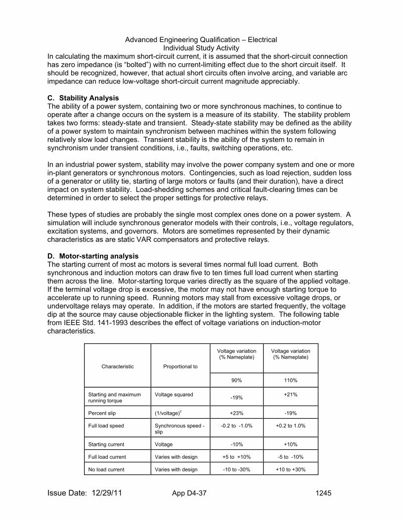
Advanced Engineering Qualification – Electrical Individual Study Activity
Issue Date: 12/29/11 App D4-37 1245
In calculating the maximum short-circuit current, it is assumed that the short-circuit connection has zero impedance (is “bolted”) with no current-limiting effect due to the short circuit itself. It should be recognized, however, that actual short circuits often involve arcing, and variable arc impedance can reduce low-voltage short-circuit current magnitude appreciably. C. Stability Analysis The ability of a power system, containing two or more synchronous machines, to continue to operate after a change occurs on the system is a measure of its stability. The stability problem takes two forms: steady-state and transient. Steady-state stability may be defined as the ability of a power system to maintain synchronism between machines within the system following relatively slow load changes. Transient stability is the ability of the system to remain in synchronism under transient conditions, i.e., faults, switching operations, etc. In an industrial power system, stability may involve the power company system and one or more in-plant generators or synchronous motors. Contingencies, such as load rejection, sudden loss of a generator or utility tie, starting of large motors or faults (and their duration), have a direct impact on system stability. Load-shedding schemes and critical fault-clearing times can be determined in order to select the proper settings for protective relays. These types of studies are probably the single most complex ones done on a power system. A simulation will include synchronous generator models with their controls, i.e., voltage regulators, excitation systems, and governors. Motors are sometimes represented by their dynamic characteristics as are static VAR compensators and protective relays. D. Motor-starting analysis The starting current of most ac motors is several times normal full load current. Both synchronous and induction motors can draw five to ten times full load current when starting them across the line. Motor-starting torque varies directly as the square of the applied voltage. If the terminal voltage drop is excessive, the motor may not have enough starting torque to accelerate up to running speed. Running motors may stall from excessive voltage drops, or undervoltage relays may operate. In addition, if the motors are started frequently, the voltage dip at the source may cause objectionable flicker in the lighting system. The following table from IEEE Std. 141-1993 describes the effect of voltage variations on induction-motor characteristics.
Characteristic Proportional to
Voltage variation (% Nameplate)
Voltage variation (% Nameplate)
90% 110%
Starting and maximum running torque
Voltage squared -19%
+21%
Percent slip (1/voltage)2 +23% -19%
Full load speed Synchronous speed - slip
-0.2 to -1.0% +0.2 to 1.0%
Starting current Voltage -10% +10%
Full load current Varies with design +5 to +10% -5 to -10%
No load current Varies with design -10 to -30% +10 to +30%
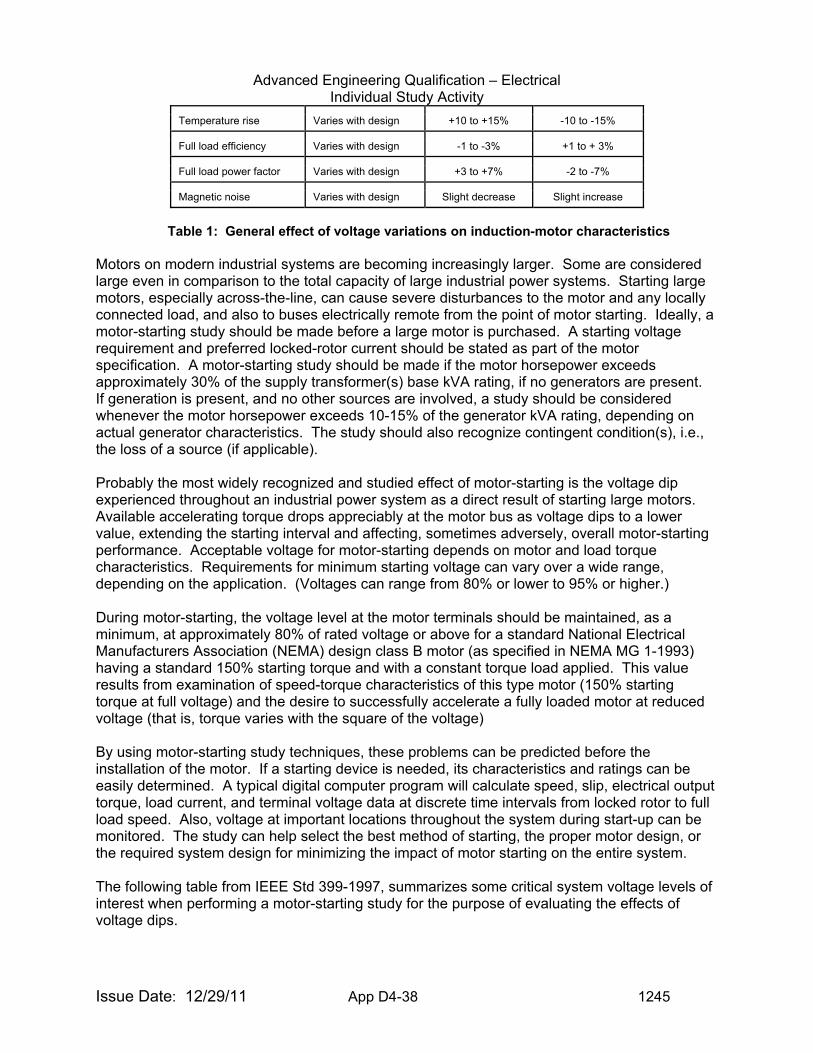
Advanced Engineering Qualification – Electrical Individual Study Activity
Issue Date: 12/29/11 App D4-38 1245
Temperature rise Varies with design +10 to +15% -10 to -15%
Full load efficiency Varies with design -1 to -3% +1 to + 3%
Full load power factor Varies with design +3 to +7% -2 to -7%
Magnetic noise Varies with design Slight decrease Slight increase
Table 1: General effect of voltage variations on induction-motor characteristics Motors on modern industrial systems are becoming increasingly larger. Some are considered large even in comparison to the total capacity of large industrial power systems. Starting large motors, especially across-the-line, can cause severe disturbances to the motor and any locally connected load, and also to buses electrically remote from the point of motor starting. Ideally, a motor-starting study should be made before a large motor is purchased. A starting voltage requirement and preferred locked-rotor current should be stated as part of the motor specification. A motor-starting study should be made if the motor horsepower exceeds approximately 30% of the supply transformer(s) base kVA rating, if no generators are present. If generation is present, and no other sources are involved, a study should be considered whenever the motor horsepower exceeds 10-15% of the generator kVA rating, depending on actual generator characteristics. The study should also recognize contingent condition(s), i.e., the loss of a source (if applicable). Probably the most widely recognized and studied effect of motor-starting is the voltage dip experienced throughout an industrial power system as a direct result of starting large motors. Available accelerating torque drops appreciably at the motor bus as voltage dips to a lower value, extending the starting interval and affecting, sometimes adversely, overall motor-starting performance. Acceptable voltage for motor-starting depends on motor and load torque characteristics. Requirements for minimum starting voltage can vary over a wide range, depending on the application. (Voltages can range from 80% or lower to 95% or higher.) During motor-starting, the voltage level at the motor terminals should be maintained, as a minimum, at approximately 80% of rated voltage or above for a standard National Electrical Manufacturers Association (NEMA) design class B motor (as specified in NEMA MG 1-1993) having a standard 150% starting torque and with a constant torque load applied. This value results from examination of speed-torque characteristics of this type motor (150% starting torque at full voltage) and the desire to successfully accelerate a fully loaded motor at reduced voltage (that is, torque varies with the square of the voltage) By using motor-starting study techniques, these problems can be predicted before the installation of the motor. If a starting device is needed, its characteristics and ratings can be easily determined. A typical digital computer program will calculate speed, slip, electrical output torque, load current, and terminal voltage data at discrete time intervals from locked rotor to full load speed. Also, voltage at important locations throughout the system during start-up can be monitored. The study can help select the best method of starting, the proper motor design, or the required system design for minimizing the impact of motor starting on the entire system. The following table from IEEE Std 399-1997, summarizes some critical system voltage levels of interest when performing a motor-starting study for the purpose of evaluating the effects of voltage dips.
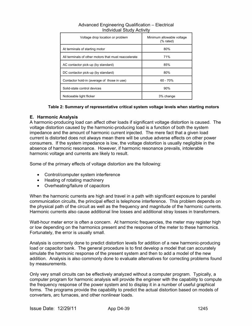
Advanced Engineering Qualification – Electrical Individual Study Activity
Issue Date: 12/29/11 App D4-39 1245
Voltage drop location or problem Minimum allowable voltage (% rated)
At terminals of starting motor 80%
All terminals of other motors that must reaccelerate 71%
AC contactor pick-up (by standard) 85%
DC contactor pick-up (by standard) 80%
Contactor hold-in (average of those in use) 60 - 70%
Solid-state control devices 90%
Noticeable light flicker 3% change
Table 2: Summary of representative critical system voltage levels when starting motors
E. Harmonic Analysis A harmonic-producing load can affect other loads if significant voltage distortion is caused. The voltage distortion caused by the harmonic-producing load is a function of both the system impedance and the amount of harmonic current injected. The mere fact that a given load current is distorted does not always mean there will be undue adverse effects on other power consumers. If the system impedance is low, the voltage distortion is usually negligible in the absence of harmonic resonance. However, if harmonic resonance prevails, intolerable harmonic voltage and currents are likely to result. Some of the primary effects of voltage distortion are the following:
• Control/computer system interference • Heating of rotating machinery • Overheating/failure of capacitors
When the harmonic currents are high and travel in a path with significant exposure to parallel communication circuits, the principal effect is telephone interference. This problem depends on the physical path of the circuit as well as the frequency and magnitude of the harmonic currents. Harmonic currents also cause additional line losses and additional stray losses in transformers. Watt-hour meter error is often a concern. At harmonic frequencies, the meter may register high or low depending on the harmonics present and the response of the meter to these harmonics. Fortunately, the error is usually small. Analysis is commonly done to predict distortion levels for addition of a new harmonic-producing load or capacitor bank. The general procedure is to first develop a model that can accurately simulate the harmonic response of the present system and then to add a model of the new addition. Analysis is also commonly done to evaluate alternatives for correcting problems found by measurements. Only very small circuits can be effectively analyzed without a computer program. Typically, a computer program for harmonic analysis will provide the engineer with the capability to compute the frequency response of the power system and to display it in a number of useful graphical forms. The programs provide the capability to predict the actual distortion based on models of converters, arc furnaces, and other nonlinear loads.
Advanced Engineering Qualification – Electrical Individual Study Activity
Issue Date: 12/29/11 App D4-40 1245
F. Switching Transients Analysis Switching transients severe enough to cause problems in industrial power systems are most often associated with inadequate or malfunctioning breakers or switches and the switching of capacitor banks and other frequently switched loads. The arc furnace system is most frequently studied because of its high frequency of switching and the related use of capacitor banks. By properly using digital computer programs or a transient network analyzer (TNA), these problems can be detected early in the design stage. In addition to these types of switching transient problems, digital computer programs and the TNA can be used to analyze other system anomalies, such as lighting arrester operation, ferroresonance, virtual current chopping, and breaker transient recovery voltage. G. Reliability Analysis When comparing various industrial power system design alternatives, acceptable system performance quality factors (including reliability) and cost are essential in selecting an optimum design. A reliability index is the probability that a device will function without failure over a specified time period. This probability is determined by equipment maintenance requirements and failure rates. Using probability and statistical analyses, the reliability of a power system can be studied in depth with digital computer programs. Reliability is most often expressed as the frequency of interruptions and expected number of hours of interruptions during one year of system operation. Momentary and sustained system interruptions, component failures, and outage rates are used in some reliability programs to compute overall system reliability indexes at any node in the system, and to investigate sensitivity of these indexes to parameter changes. With these results, economics and reliability can be considered to select the optimum power system design. H. Cable Ampacity Analysis Cable ampacity studies calculate the current-carrying capacity (ampacity) of power cables in underground or above ground installations. This ampacity is determined by the maximum allowable conductor temperature. In turn, this temperature is dependent on the losses in the cable, both I2R and dielectric, and thermal coupling between heat-producing components and ambient temperature. The ampacity of a conductor depends on a number of factors. Prominent among these factors and of much concern to the designers of electrical distribution systems are the following:
• Ambient temperature • Thermal characteristics of the surrounding medium • Heat generated by the conductor due to its own losses • Heat generated by adjacent conductors
The ampacity calculations are extremely complex. This is due to many considerations, some examples of which are heat transfer through the cable insulation and sheath, and, in the case of underground installations, heat transfer to duct or soil as well as from duct bank to soil. Other considerations include the effects of losses caused by proximity and skin effects. In addition, depending on the installation, the cable-shielding system may introduce additional losses. The analysis involves the application of thermal equivalents of Ohm’s and Kirchhoff’s laws to a thermal circuit.
Advanced Engineering Qualification – Electrical Individual Study Activity
Issue Date: 12/29/11 App D4-41 1245
I. Ground Mat Analysis Virtually every exposed metallic object in an industrial facility is connected to ground, either deliberately or by accident. Under normal operating conditions, these conductors will be at the same potential as the surrounding earth. However, during ground faults, the absolute potential of the grounding system will rise (often to thousands of volts) along with any structural steel tied to the grounding system. Because any metal is a relatively good conductor, the steelwork everywhere will be essentially the same voltage for most industrial installations. Most soils are poor conductors, however, and the flow of fault current through the earth will create definite and sometimes deadly potential gradients. Ground mat studies calculate the voltage difference between the grounding grid and points at earth’s surface and evaluate the shock hazard involved. A ground mat study has one primary purpose: to determine if a ground mat design will limit the neutral-to-ground voltages normally present during ground faults to values that the average person can tolerate. Under ground-fault conditions, the flow of current will result in voltage gradients within and around the substation, not only between structures and nearby earth, but also along the ground surface. In a properly designed system, this gradient should not exceed the limits that can be tolerated by the human body. Some of the factors that are considered in a ground-mat study are the following:
• Fault-current magnitude and duration • Geometry of the grounding system • Soil resistivity • Probability of contact • Human factors such as
o Body resistance o Standard assumptions on physical conditions of the individual
J. Protective Device Coordination Analysis The objective of a protection scheme in a power system is to minimize hazards to personnel and equipment while allowing the least disruption of power service. Coordination studies are required to select or verify the clearing characteristics of devices such as fuses, circuit breakers, and relays used in the protection scheme. These studies are also needed to determine the protective device settings that will provide selective fault isolation. In a properly coordinated system, a fault results in interruption of only the minimum amount of equipment necessary to isolate the faulted portion of the system. The power supply to loads in the remainder of the system is maintained. The goal is to achieve an optimum balance between equipment protection and selective fault isolation that is consistent with the operating requirements of the overall power system. Short-circuit calculations are a prerequisite for a coordination study. Short-circuit results establish minimum and maximum current levels at which coordination must be achieved and which aid in setting or selecting the devices for adequate protection. Traditionally, the coordination study has been performed graphically by manually plotting time-current operating characteristics of fuses, circuit breaker trip devices, and relays, along with conductor and transformer damage curves - all in series from the fault location to source. Log-log scales are used to plot time versus current magnitudes. These “coordination curves” show graphically the
Advanced Engineering Qualification – Electrical Individual Study Activity
Issue Date: 12/29/11 App D4-42 1245
quality of protection and coordination possible with the equipment available. They also permit the verification/confirmation of protective device characteristics, settings, and ratings to provide a properly coordinated and protected system. With the advent of the personal computer, the manual approach to protective device coordination is being replaced by computer programs. The programs provide a graphical representation of the device coordination as it is developed. In the future, computer programs are expected to use expert systems based on practical coordination algorithms to further assist the protection engineer. Whether the coordination is done manually or by computer, it is necessary for the engineer to “describe” the system. The information needed to perform a coordination study is a single-line diagram showing the following:
• Protective device manufacture and type • Protective device ratings • Trip settings and available range • Short-circuit current at each system bus (three-phase and line-to-ground) • Full load current of all loads • Voltage level at each bus • Transformer kVA, impedance, and connections (delta-wye, etc.) • Current transformer (CT) and potential transformer (PT) ratios • Cable size, conductor material, and insulation • all sources and ties
For criteria that establish protection requirements for Class 1E power systems and equipment see IEEE Std 741-1997, IEEE Standard Criteria for the Protection of Class 1E Power Systems and Equipment in Nuclear Power Generating Stations. This standard provides guidance for switchgear and bus protection, bus voltage monitoring schemes, motor protection, diesel generator protection, load shedding and sequential loading, surge protection, protection of electrical penetrations, and protective devices for direct geared valve actuator motors. The following information was extracted from the referenced standard for AC power distribution systems. Switchgear and bus protection For recommended practices in application of overcurrent relays, directional relays, differential relays for bus protection, and ground fault relaying, refer to IEEE Std. 141-1993, IEEE Std. 242-1986, and IEEE Std. 666-1991. For supplemental information on ground protection practices, refer to IEEE Std. 142-1991. Bus voltage monitoring schemes Bus voltage monitoring schemes that are used for disconnecting the preferred power source, load shedding, and starting the standby power sources shall meet the following:
• Bus voltage shall be detected directly from the class 1E bus to which the standby power source is connected.
• Upon sensing preferred power supply degradation, the condition shall be alarmed in the
main control room. On sensing preferred power supply degradation to an unacceptable low voltage condition, the affected preferred power supply shall be automatically disconnected from the Class 1E buses.
Advanced Engineering Qualification – Electrical Individual Study Activity
Issue Date: 12/29/11 App D4-43 1245
• Each division shall have an independent scheme of detection for degraded voltage and
loss of voltage conditions. Within each division, common equipment may be used for the detection of both conditions.
• Each scheme shall monitor all three phases. The protection system design shall be
such that a blown fuse in the voltage transformer circuit or other single phasing condition will not cause incorrect operation, nor prevent correct operation, of the scheme. Means shall be provided to detect and identify these failures.
• The design shall minimize unwanted operation of the standby power sources and
disconnection of the preferred power supply. The use of coincident logic and time delay to override transient conditions is a way to accomplish this.
• Capability for test and calibration during power operation shall be provided.
• The selection of undervoltage and time delay setpoints shall be determined from an
analysis of the voltage requirements of the Class 1E loads at all on-site distribution levels.
• Indication shall be provided in the control room for any bypass incorporated in the
design. Reference 5 provides a discussion on the application of the voltage protection relays at nuclear power plants. Feeder circuit protection For recommended practice on motor protection, refer to IEEE Std. C37.96-1988, IEEE Std. 242-1986, and IEEE Std. 666-1991. Additional requirements for the selection of a protective device for direct geared valve actuator motors will be discussed later. The feeder circuit protection should consider any expected operating conditions of the motor that may require electrical system demands above the motor’s nameplate rating such as the following:
• Motor service factor • Pump runout conditions • Operation at other than rated voltage
For recommended practice on power transformer protection, refer to IEEE Std. C37.91-1985 and IEEE Std. 666-1991. For recommended practice on feeder circuit to power distribution panel protection, refer to IEEE Std. 141-1993 and IEEE Std. 242-1986. For criteria for isolation and separation of non-class 1E circuits from Class 1E circuits, refer to IEEE Std 384-1992. Standby power supply protection For diesel generator protection recommended practice, refer to IEEE Std. 242-1986. In the manual control mode, synchronizing interlocks should be provided to prevent incorrect synchronization whenever a standby power source is required to operate in parallel with the preferred power supply.
Advanced Engineering Qualification – Electrical Individual Study Activity
Issue Date: 12/29/11 App D4-44 1245
When a standby power supply is being operated in parallel with the preferred power supply, protection shall be provided to separate the two supplies if either becomes degraded to an unacceptable level. This protection shall not lockout or prevent the availability of the power supply that is not degraded. Load shedding and sequential loading An automatic load shedding and sequential loading scheme may be included to ensure that the preferred or standby power sources can be loaded while maintaining voltage and frequency within acceptable limits. The Class 1E bus load shedding scheme should automatically prevent shedding during sequencing of the emergency loads to the bus when connected to the standby power source. If the preferred or standby power source breaker is tripped during or subsequent to loading, the load shedding and sequential loading scheme shall be arranged to be automatically reset to perform its function in the event that the loads are to be reapplied. Surge protection For surge protection of equipment and systems, refer to IEEE Std. 141-1993 and IEEE Std. 242-1986. For surge protection of induction motors, refer to IEEE Std. C37.96-1988. For recommendations in design and installation of low-energy, low-voltage signal circuits associated with solid-state electronic equipment, refer to IEEE Std. 518-1982. Surge protection shall be provided to protect the shunt field of dc valve actuator motors. This surge protection may take the form of a resistor in the motor control center-wired in parallel with the shunt field to provide a discharge path for the shunt field’s inductive voltage surges. For guidance in the application of surge arresters to all types of power circuits and equipment, refer to IEEE Std. C62.2-1987. Refer to IEEE Std. C62.41-1991 for guidance in determining the surge voltage for low-voltage equipment, and to IEEE Std. C62.45-1992 to provide guidance for tests that should be used to determine the surge withstand capability of the equipment used on low-voltage circuits. DC power system For recommended practice on protection of batteries, refer to IEEE Std. 946-1992. The dc power distribution system should be provided with coordinated protection. Coordination for dc power system circuits should include the main bus protective devices and the protective devices used in branch circuits, in switchgear control circuits, and in relay and process control panels. Care shall be taken to use appropriate correction factors or dc trip characteristic curves for protection devices. For criteria for isolation and separation of non-class 1E circuits from Class 1E circuits, refer to IEEE Std. 384-1992. Ground detection monitoring shall be provided for ungrounded systems. Battery chargers shall be provided with current limiting features or overload protection, reverse current protection, output undervoltage, and overvoltage alarms and/or trips. For additional guidance on the protection of battery chargers, refer to IEEE Std. 446-1987.
Advanced Engineering Qualification – Electrical Individual Study Activity
Issue Date: 12/29/11 App D4-45 1245
Instrumentation and control power system For guidance on protection for inverters, refer to IEEE Std. 446-1987. For information on ground protection practices, refer to IEEE Std. 142-1991 and IEEE Std. C62.92.3-1993. For criteria for isolation and separation of non-class 1E circuits from Class 1E circuits, refer to IEEE Std. 384-1992. Where a rectifier-type power supply is used as a source for an inverter, it shall be provided with reverse current protection, current-limiting features or overload protection, and output undervoltage and overvoltage protection. The instrumentation and control power distribution system should be provided with coordination protection. Since inverters and motor generator sets are sources of limited short-circuit current, special attention must be given to integrating protective device sensitivity and system available fault current. Coordination should include the protective devices in the alternate supply, inverters, static switches, distribution panels, instrumentation panels and racks, and other equipment powered from the system. Where an instrumentation and control power bus is supplied by an inverter with current limiting characteristics and an automatic transfer has been provided to an alternative source with higher available current, this alternate source may be used in order to achieve the coordinated protection described above. Ground detection monitoring shall be provided for ungrounded systems. The instrumentation and control power system should be provided with undervoltage, overvoltage, and underfrequency protection. Where its power is supplied from a static inverter, overfrequency protection should also be provided. For recommended practice on alarms and indication, refer to IEEE Std. 944-1986. Primary containment electrical penetration assemblies An electrical penetration assembly shall be considered as part of the cable system between the load and the primary interrupting device. For guidance in the application of electrical circuit protection, refer to IEEE Std. 242-1986, which includes information also applicable to electrical penetrations. Short circuit, overload, and continuous current ratings and capabilities of the electrical penetration are defined in IEEE Std. 317-1983. The electrical penetration assemblies installed as part of the containment structure may require special consideration in the selection of their protection. This special consideration arises where the potential exists for a fault inside containment to result in a penetration seal failure, such that a breach of containment may occur. Where a penetration assembly can indefinitely withstand the maximum current available due to a fault inside containment, no special consideration is required. Electrical penetrations requiring special consideration (i.e., where protection is required to ensure containment integrity) shall be provided with dual primary protection operating separate interrupting devices, or primary and backup protection operating separate interrupting devices. The time-current curves of the dual primary protection or the primary and backup protection shall coordinate with the time-current capability curve of the electrical penetration to be
Advanced Engineering Qualification – Electrical Individual Study Activity
Issue Date: 12/29/11 App D4-46 1245
protected. Valve actuator motors The selection of a protective device for the direct geared valve actuator motor shall ensure that the time current characteristic of the protective device is coordinated with the time current characteristic of the motor, as derived from the motor time temperature data. In addition, the coordination shall ensure the allowable duty cycle of the valve is completed without compromising the motor thermal withstand capability, while allowing margin for variations in current drawn by the motor, or in the thermal characteristics of the protective device, or both. The protective device(s) shall be selected to prevent the following:
• Motor overheating due to locked-rotor conditions; • Motor overheating due to anticipated overloads; • Nuisance trips during acceleration; • Nuisance trips due to anticipated overloads; • Nuisance trips during operation within the duty cycle of the valve.
To protect the motor during locked-rotor conditions, the protective device maximum trip time shall not exceed the allowable safe locked-rotor time, and the minimum trip time shall not be less than the acceleration time (typically less than 1 second). Protective devices shall be coordinated with the motor allowable operating time corresponding to nominal torque and anticipated overloads. Typical anticipated valve overloads fall in the range of 150 -300% of the valve actuator motor nominal torque, depending on the actuator type and application. Short-circuit protection shall be provided for the valve actuator motor. If the device for short-circuit protection contains an overload element, this element shall be coordinated with the valve actuator motor thermal overload device. The following shall also be considered in the derivation and coordination of the protective device setpoints:
• Tolerance (accuracy) of the protective device; • The effect of ambient temperature; • The effect of motor terminal operating voltage extremes
Valve actuator motor current values shall be obtained from the valve manufacturer at nominal torque, selected overload torque (150-300% of nominal torque), and locked-rotor torque. The current values shall be measured at nominal voltage and either measured or calculated for anticipated voltages at the terminals of the motor. These currents shall be considered in the final selection of the overload protection device. The following information is required to select overload heaters:
• Valve actuator motor currents at rated voltage and expected minimum and maximum voltages:
o Rated nominal current; o Current at twice the rated nominal torque or at a selected torque for which the
Advanced Engineering Qualification – Electrical Individual Study Activity
Issue Date: 12/29/11 App D4-47 1245
corresponding thermal capability is available; o Locked-rotor current.
• Time temperature characteristics of motor:
o Rated nominal current; o Time the motor can safely carry current corresponding to twice nominal torque; o Locked-rotor duration the motor can safely tolerate.
• Thermal Overload Relay (TOR) time-current curves and TOR type and selection table and TOR application guidelines from the selected manufacturer or from IEEE Std. C37.96-1988;
• Motor rated ambient temperature, insulation class, rated nominal torque, and rated speed;
• Stroke time of the valve actuator; • Maximum allowable duty cycle; • TOR ambient temperature during normal and abnormal plant operating conditions (if
ambient compensated relays are not used). Sample calculations of thermal overload relay heater selection for ac and dc valve actuator motors are provided in IEEE Std. 741-1997, Annex B. K. DC Auxiliary Power System Analysis The need for direct current (dc) power system analysis of emergency standby power supplies has steadily increased during the past several years in data processing facilities, long distance telephone companies, and generating stations. DC emergency power is used for circuit breaker control, protective relaying, inverters, instrumentation, emergency lighting, communications, annunciators, fault recorders, and auxiliary motors. The introduction of computer techniques to dc power systems analysis has allowed a more rapid and rigorous analysis of these systems compared to earlier manual techniques. Examples of Findings Involving Electrical Analysis 1. Kewaunee - FIN 05000305/2005002-02, Green finding was identified for failure to
provide adequate relay setpoint calibration tolerances on safety buses 1-5 and 1-6 loss of voltage relays.
2. Kewaunee - NCV 05000305/2005002-03, Green finding was identified for failure to evaluate the effects of over-dutied circuit breakers on non-safety related 4160 VAC buses 1-1, 1-2, 1-3, and 1-4. The circuit breakers were over-dutied based on the calculated potential fault currents at the bus.
3. Kewaunee - FIN 05000305/2005002-01, Green finding was identified for lack of adequate electrical systems coordination between the undervoltage and overcurrent protection on 4160 VAC safety bus 1-5.
4. Fermi 2 - NCV 05000341/2006015-01, Green finding was identified for failure to maintain surveillance test procedures for the Division 1 Emergency Diesel Generators (EDGs) that were appropriate to the circumstances.
5. Fermi 2 - NCV 0500341/2006015-02, Green finding was identified for the failure to adequately review the suitability of the design of new 480 volt circuit breakers used for all four EDG Service Water pumps and the engine room supply ventilation fans for both Division 1 EDGs.
6. D.C. Cook - NCV 315,316/2001019-01, A finding was identified for failure to ensure that coordination and selective tripping was provided. The existing current transformers were
Advanced Engineering Qualification – Electrical Individual Study Activity
Issue Date: 12/29/11 App D4-48 1245
undersized and were not suitable for their application. 7. D. C. Cook - NCV 315,316/2001019-04, Green finding was identified for failure to
address a long-standing design deficiency with 4.16 kV air circuit breakers. The fault current available on 4.16 kV load feeders could exceed the circuit breaker’s momentary interrupting capacity rating of 250 MVA during a 3-phase bolted fault condition.
Examples of Recent LERs Involving Electrical Analysis $ Point Beach – LER 266,301/2005-005-00, Postulated Faults with Electrical Current in
Excess of Maximum Interrupt Ratings and Nonconservative Degraded Voltage Time Delay Relay Setting Technical Specification
$ San Onofre – LER 361/2005-003-00, Relay Settings For The Degraded Grid Voltage Protection System Could Cause Early Separation From Offsite Power Sources During A Design Basis Event
Examples of Information to Request for Inspection of Electrical Issues For any inspection to be successful, the inspector must request the right information in order to evaluate whether the licensee is correctly interpreting and applying requirements, industry standards, lessons learned and industry best practices. The following examples may be useful in requesting licensee information. $ List of Electrical Calculations $ List of Electrical Design Basis documents $ List of Recent Electrical Design Changes $ List of Electrical Work-a-rounds $ List of Problem Reports on Electrical Issues in the Corrective Action Program $ Technical Specifications for Electrical Distribution system $ Elementary and One-line Drawings of the Electrical Distribution System $ Updated Final Safety Analysis Report $ Vendor Manuals $ Manufacturers data sheets $ Manufacturers test report data $ Equipment specifications $ Protective Relay Setpoint Calculations and Setting Sheets $ Protective Relay Calibration Procedures $ Equipment Surveillance Test Procedures $ Electrical System Operating Procedures $ Industry Operating Experience Electrical Calculations Items of Interest to Inspectors: When reviewing electrical calculations the inspector should verify that inputs and assumptions are appropriate (i.e., they should be consistent with the electrical distribution system), and that the results are correctly translated into appropriate design output documents such as relay settings, equipment specifications, drawings and procedures. Also, the electrical system should be maintained and operated in accordance with these results or they should be revised to reflect the changes in system operation. Training associated with AC Analysis of Power Systems: S&C Electric Company – Grounding in Electrical Power Distribution Systems http://www.sandc.com/services/seminars/grounding-in-electrical-power-distribution-systems-seminar.asp
Advanced Engineering Qualification – Electrical Individual Study Activity
Issue Date: 12/29/11 App D4-49 1245
S&C Electric Company – Distribution Overcurrent Protection and Coordination http://www.sandc.com/services/seminars/distribution-overcurrent-protection-and-coordination-seminar.asp S&C Electric Company – Power System Stability and Control http://www.sandc.com/services/seminars/power-system-stability-and-control-seminar.asp S&C Electric Company – Short Circuit Analysis of Electrical Power Systems http://www.sandc.com/services/seminars/short-circuit-analysis-of-electrical-power-systems-seminar.asp ETAP – E-115N, Power Systems Engineering http://etap.com/training/events
ETAP – E-153, Short Circuit, Device Evaluation, & Arc Flash http://etap.com/training/events
ETAP – E-215, Advanced Power System Engineering http://etap.com/training/events
Univ. of Wisconsin – Madison, Coordination of Industrial and Commercial Electric Power Distribution Systems Georgia Tech – Power System Relaying: Theory and Applications Georgia Tech – Protective Relaying Conference Georgia Tech – Power Distribution System Grounding and Transients EVALUATION CRITERIA: Upon completion of the tasks in this guide, you will be asked to demonstrate your
understanding of AC Analysis for Power Systems by discussing the topics below with a senior electrical inspector or reviewer who is listed as qualified on this topic.
1. Discuss the different types of analysis performed on AC Power Systems. 2. Discuss the purpose(s) of the different types of analysis used for AC Power
Systems. 3. Discuss how the different analysis types might be useful for inspections.
TASKS:
1. Review the References and Discussion herein. 2. Be able to explain how the results of various analysis such as load flow analysis,
short-circuit analysis, motor-starting analysis, cable ampacity, and protective device coordination analysis are used in the design and operation of the electrical distribution system.
3. Answer the question: “What is meant by minimum expected voltage and minimum required voltage as referenced to the highest voltage safety-related bus?”
4. Answer the question: “What is the output (i.e. important calculated parameter) in the motor starting calculation and what are the criteria for the motor starting calculation?”
5. Answer the question: “What are two reasons that the degraded voltage relay must have a time delay, and how is the minimum time delay determined?”
6. Answer the question: “How is the load flow program used to determine the minimum required voltage at the point where the potential transformers for the degraded voltage relays sense voltage?”
7. Answer the question: “Suppose a plant had excellent voltage calculations at the time of initial startup and a number of years later the startup transformer failed. And suppose a replacement transformer obtained from another utility had the same kVA
Advanced Engineering Qualification – Electrical Individual Study Activity
Issue Date: 12/29/11 App D4-50 1245
and voltage ratings as the failed transformer, what is another key parameter of the new transformer that must be checked to ensure that the voltage calculations will remain valid with the new transformer?”
8. Answer the question: ”On a nominal 4160 V system, what would be the rated voltage
of the motors?” 9. Answer the question: “What are some of the problems that can occur if adequate
voltage is not provided in an auxiliary distribution system for a power plant?” Answer this question in terms of electrical and mechanical system performance as opposed to reactor transients.
DOCUMENTATION: Electrical Inspector Advanced-Level Signature Card ISA-EE-6.
Advanced Engineering Qualification – Electrical Individual Study Activity
Issue Date: 12/29/11 App D4-51 1245
TOPIC: (ISA-EE-7) DC Analysis for Power Systems PURPOSE: The purpose of this guide is to improve the ability of an inspector to
inspect and to evaluate this electrical area. The critical skills are to understand the important functions of the DC distribution System and to understand potential vulnerabilities in design, testing, and operation. The topic has safety significance because DC loads are important in normal operation and especially in accident scenarios that can result in the loss of function or degraded condition of safety related or risk-significant loads. The performance deficiency may be on inadequate design analysis, poor testing, poor maintenance or other causes.
COMPETENCY AREA: INSPECTION LEVEL OF EFFORT: As determined by Branch Chief or supervisor REFERENCES: 1. IEEE Std 450 IEEE Recommended Practice for Maintenance, Testing, and
Replacement of Vented Lead-Acid Batteries for Stationary Applications 2. IEEE Std 484 IEEE Recommended Practice for Installation Design and Installation of
Vented Lead-Acid Batteries for Stationary Applications 3. IEEE Std 485 Recommended Practice for Sizing Lead-Acid Batteries for Stationary
Applications 4. IEEE Std 535 IEEE Standard Qualification of Class 1E Lead Storage Batteries for
Nuclear Power Generating Stations 5. IEEE Std 650 Standard for Qualification of Class 1E Battery Chargers and Inverters for
Nuclear Generating Stations 6. IEEE Std 946 IEEE Recommended Practice for the Design of DC Auxiliary Power
Systems for Generating Stations 7. IEEE Std 1375 IEEE Guide for the Protection of Stationary Batteries 8. IEEE Std 1491 IEEE Guide for Selection and Use of Battery Monitoring
Equipment in Stationary Applications 9. Regulatory Guide 1.129, “Maintenance Testing, and Replacement of Vented Lead-
Acid Storage Batteries for Nuclear power plants, Revision 2” 10. Regulatory Guide 1.32, “Criteria for Power Systems for Nuclear Power Plants,
Revision 2” 11. Information Notice 85-74, “Station Battery Problems, August 29, 1985” DISCUSSION: Typical DC Power Distribution System The Class 1E 125-Vdc electrical system is composed of physically separate, electrically independent, redundant trains. Each train contains a number of lead-acid batteries connected in series. The batteries are continuously connected to the DC distribution system and are maintained in a fully charged condition by their respective battery chargers during normal plant operations. The batteries have a passive role in the system during normal operations. When an abnormal condition results in a failure of the battery charger to power all DC loads, the associated battery is called upon to provide the necessary power, thereby ensuring continuity of operation. The batteries may only be needed during the short period required for starting the emergency diesel generators (EDGs), or they may be called upon to supply power for an extended period of time in the event of a loss of all AC power. In either case, it is essential that
Advanced Engineering Qualification – Electrical Individual Study Activity
Issue Date: 12/29/11 App D4-52 1245
the batteries function properly if the plant safety systems are to operate as required. Each train provides power for a redundant ESF load group, and is arranged so that the battery or any one charger can independently supply the buses in that train. Normally, one battery charger in each train rectifies 480-Vac power to 125-Vdc power to supply the system loads and to maintain the battery in a fully charged condition. The battery in each train will supply the system loads if the in-service battery charger fails or if a complete loss of offsite and onsite AC power occurs. The 125-vdc system satisfies the following design criteria: A. The seismic qualification criteria are satisfied because the system is designed to withstand
the effects of earthquakes without the loss of the ability to perform its safety functions. Since the 125-vdc system is designed to remain functional in the event of a safe shutdown earthquake, it is designated Safety- Related and Seismic Category I.
B. The quality assurance criteria are satisfied because the system is designed, fabricated, created, installed, and tested to quality standards commensurate with the importance of the safety functions to be performed.
C. The redundancy/diversity criteria are satisfied because the system has sufficient independence, redundancy, and testability to perform its safety functions assuming a single failure.
The 125-vdc system satisfies the following specific redundancy/diversity requirements: A. The system is an ungrounded DC system for safety and greater reliability; B. The system has physically separate and independent trains to support the two trains of ESF
loads (A and B); C. Each train is redundant, with no cross-connections, so that the failure of one train does not
affect the other; and D. Each train supplies dc electrical power at a sufficient capacity for normal plant startup,
operation, or shutdown and during a total loss of ac power when under worst-case accident loading.
E. The environmental qualification criteria are satisfied because the system is designed to accommodate the effects of and to be compatible with the environmental conditions associated with normal operation, maintenance, testing, and postulated accidents, including loss of coolant accidents.
F. The fire protection criteria are satisfied because the system is designed and located to minimize the probability and effects of fires and explosions. Fire detection and suppression systems minimize the adverse effects of fire.
G. The environmental protection criteria are satisfied because the system is designed to
withstand the effects of natural phenomena such as earthquakes, tornadoes, hurricanes, floods, tsunami, and seiches without the loss of the ability to perform its safety functions, and because the system is appropriately protected against dynamic effects, including missiles, pipe whips, and discharging fluids.
Each battery charger is powered from a different 480-vac ESF Motor Control Center (MCC). Normally, each train is aligned such that the dc buses are cross-connected through the battery breakers with the bus tie breaker open (closing the tie breaker would require 10 CFR 50.59 evaluation). This arrangement improves reliability during fault conditions because the bus tie breaker is a non-tripping breaker. Since the battery chargers are not designed with load-sharing capabilities, only one battery charger is in operation to supply the bus loads and maintain the battery in a fully charged condition. The major loads on each train include two inverters, two dc distribution panels, and emergency DC lighting. The DC distribution panels supply power to the following types of loads: annunciators, indicating lights, solenoid valves, control relays, small dc
Advanced Engineering Qualification – Electrical Individual Study Activity
Issue Date: 12/29/11 App D4-53 1245
motors (breaker charging motors), switchgear (close and tripping power for all (6.9 kV or 12.47 kV, 4.16 kV, and some 480 V breakers), reactor trip and trip bypass breakers (close, trip, and indication power), and the EDGs (field flash, air start solenoid, control circuit, and fuel pump power). Battery Chargers The battery chargers are the normal power supplies for the DC buses. The basic components installed in each battery charger cabinet are:
• An input power breaker to supply the transformer with power from the 480 Vac ESF MCC;
• A 480/120 V step-down transformer. The transformer also provides physical separation between the 480 Vac system and the 125 Vdc system;
• A solid-state rectifier to convert the 120 Vac output from the transformer into a smooth, nominal 125 Vdc output;
• An output power breaker to supply the output from the rectifier to the 125 Vdc ESF bus, and,
• A charger failure relay to detect a loss of charger output due to a failure in the charger's ac power input or dc power output. Note: The charger failure relays provide input to a common trouble alarm for each train. The alarm associated with the charger failure relays is delayed approximately 45 seconds by the alarm circuitry in order to prevent normal fluctuations in the charger output from causing a false alarm.
The battery charger is provided with a fail-safe filtering circuit across the output to limit any transient change in dc voltage to + 2% of the rated voltage in the event that the battery is disconnected from the charger. The charger is designed to prevent the battery from discharging back into any internal charger load in the event of an ac power supply failure or a charger failure. Each charger is designed and sized large enough so that a single charger per train would be capable of carrying the required post-accident loads while recharging the battery in that train. Batteries The batteries serve as backup DC power supplies for the 125-Vdc buses. If the operating battery charger in a train should fail, the associated battery will automatically supply power to the dc buses until the standby battery charger can be placed in service. In the event of a loss of a station blackout, the batteries will automatically supply power to the dc buses until ac power is restored (e.g., by automatic startup of the EDGs) or for a specified time interval which depends on the loads being supplied. The proper battery size (i.e., battery capacity) for the plant is determined by the amount of starting and running current each load draws and the length of time each load needs to be supplied from the batteries during an accident. The battery duty cycles, or accident load profiles, are created from the list of design loads by plotting the total current drawn by those loads versus time. Each battery is located in a separate room. The battery room exhaust system continuously operates to ventilate the battery rooms to reduce any hydrogen accumulation (especially during charging operations), and exhausts it to the atmosphere. A loss of ventilation will not result in hazardous hydrogen levels until approximately 15 days later. In addition, the loss of ventilation to either battery room is annunciated in the control room. Each room has a space heater to maintain the air temperature between 70E F and 80E F. A low air temperature in either battery room is also annunciated in the control room. The combined effects of ventilation and the battery room space heaters ensure that the maximum temperature
Advanced Engineering Qualification – Electrical Individual Study Activity
Issue Date: 12/29/11 App D4-54 1245
spread for all connected cells does not exceed 5E F. Operation with high temperature gradients between cells contributes to nonuniform charging and premature aging of cells. Typically, each battery consists of 60 cells which are series -connected to achieve a nominal terminal voltage of 125 V. Each lead-acid battery cell consists of a group of positive and negative electrodes, or plates, connected together and encased in a vented, transparent container. Summary The DC electrical system supplies reliable, continuous Class 1E electrical power to ESF equipment and non-ESF equipment required for startup, normal operation, and safe shutdown of the plant. The DC system provides this power for a specified time under all plant conditions, including the complete loss of offsite and onsite ac power sources. The operability of the DC electrical power distribution system in accordance with the Technical Specifications is consistent with the initial assumptions of the accident analyses and is based upon meeting the design basis of the plant. For Design basis, the sizing of the battery follows IEEE Std 485. Testing follows IEEE Std 450 as approved and endorsed by Regulatory Guide 1.129, Maintenance, Testing, and Replacement of Vented Lead-Acid Storage Batteries for Nuclear power plants, Revision 2 Examples of Event Reports to Review for DC Distribution Systems: LER 3612008006 Loose connection bolting results in inoperable battery and
Tech Spec violation LER 2602005006 Low voltage on shutdown battery cells results in condition
prohibited by Tech Specs LER 3882005002 Degraded 125 VDC battery charger results in Tech Spec
required shutdown Examples of Findings for DC Distribution System:
• The station blackout diesel generator was found to be inoperable by the licensee because its starting battery had been allowed to completely discharge. The station blackout diesel generator had been moved from its normal storage location as a contingency for a planned maintenance outage on several Division I safety-related systems. The inspectors determined that the Division I maintenance outage contingency plan and the weekly work schedule did not plan for the return of the station blackout diesel generator to its normal storage location to get re-energized by its battery charger. The failure to maintain its starting battery charged caused the risk significant station blackout diesel generator to be inoperable and unavailable.
• A licensee failed to ensure that their procedure contained adequate verification such that
an independent observer could ensure that adequate electrical isolation had been maintained when a non-Class 1E single cell battery charger was used to charge a single battery cell on safety-related batteries. Specifically, failure to install a fuse could result in inadequate electrical isolation between the non-Class 1E single cell battery charger and safety-related battery. Without adequate isolation, a fault on the non-Class 1E charger could potentially render the safety-related battery incapable of performing its required safety function.
• Failure to Evaluate and Implement the Replacement of Electrolytic Capacitors. The
inspectors identified a Non-Cited Violation of 10 CFR Part 50, Appendix B, Criterion XVI, "Corrective Action," associated with not promptly identifying and evaluating a condition adverse to quality. Specifically, the licensee did not replace aging electrolytic capacitors
Advanced Engineering Qualification – Electrical Individual Study Activity
Issue Date: 12/29/11 App D4-55 1245
in the six Division I and Division II, 250 Vdc battery chargers in a timely manner, allowing them to go beyond the service life specified by the vendor and the plant's preventative maintenance (PM) program. In addition, routine PM activities for all six 250 Vdc battery chargers have not been performed since February 2000.
• The NRC found that the licensee had missed their prescribed calibration on the
instruments for the battery charger voltmeters. The failure to maintain the calibration frequency was considered to have low risk significance because it would not prevent the system from performing its required safety function due to the compensating margins.
• The inspectors identified a practice of performing preventive maintenance prior to the
required surveillance testing of recirculation pump trip breakers and safety-related battery chargers masked the as-found conditions of these components, and this practice had not been evaluated. After the inspectors noted the MSIV preconditioning issue in February 2003, licensee corrective action included a review of other outage-related activities for unacceptable preconditioning. Licensee corrective action was narrow in scope and did not identify the RPT breaker and battery charger preconditioning issues.
Examples of Information to Request for Inspection of DC Electrical Distribution Issues: For any inspection to be successful the inspector must request the right information to evaluate whether the licensee is correctly interpreting and applying requirements, industry standards, lessons learned and industry best practices. Typical sample requests would be
• battery vendor manuals and maintenance procedures • charger vendor manuals and maintenance procedures, • wiring diagrams and schematics, • logic diagrams, • battery sizing calculation, • short circuit calculations and load lists, • completed construction tests or surveillance tests, • coordination guidance and coordination diagrams.
More specific requests for information for batteries and chargers should follow a line of questioning that examines what assurances are there that the DC system will perform its design function. To confirm battery room temperatures are acceptable: What is the worst case low and high temperature of the battery rooms throughout the year? Are these battery room temperatures taken on Operator rounds? What are recently recorded battery room temperatures? Is there temperature high and/or low alarms for the battery room? What are the alarm settings? What short term high temperature challenges does the HVAC Load Calculation for LOOP/LOCA show for the battery rooms? To confirm the battery has sufficient energy to operate required loads during accident conditions: What margin is in the battery sizing calculation? Have any DC loads changed or will be changed by Design Changes? What are the results of the Battery discharge test? What was the load time line profile? Is the load profile realistic for the requirements of the plant design and EOPs? Were there any changes in the EOPs e.g. load changes at different times, more equipment needed to be run because of Power Uprate, etc. To confirm proper dc system operation: Review Battery vendor manual and maintenance
Advanced Engineering Qualification – Electrical Individual Study Activity
Issue Date: 12/29/11 App D4-56 1245
procedures, charger vendor manual and maintenance procedures, DC wiring diagram and schematics, short circuit calculations for DC distribution system. More specific questions may be: What cable temperature was used to determine the conductor resistance used in short circuit calculations? Typical loads are: (see wiring diagram and load sheets with amperes, watts & horsepower information) DC source to Inverters for instrument bus ESF, Reactor trip switchgear, control power to 4160 VAC breakers, Diesel Generator Control panel, control power to 6900VAC (or 13kV) switchgear, ESF sequencing cabinet, control power to 480 VAC switchgear, Containment isolation valve, Rod Drive MG set switchgear, CO2 fire protection system, etc. Control applications including breaker opening and closing coils are dependent on DC voltage from the battery to the device (coil for breakers) and the actual minimum voltage for coil operation should be verified by a test. Also, breaker charging motors must have sufficient voltage to charge springs. Request voltage test documentation to support DC opening and closing coil operability and breaker charging motor operation. Walkdown Inspection Things to Look For On Batteries and Chargers:
1. Electrolyte (Water-acid) level between high and low marks on the transparent container. Electrolyte (Water-acid) appears free from particles and sediment. Sediment buildup in a battery cell can cause it to short circuit resulting in an overpressure condition.
2. No cracks in the battery cell or leakage of electrolyte. No leakage or seepage from around terminals, no evidence of corrosion at terminals, connectors or racks. Look for acid leak deposits: White is lead hydrate from a leak around negative terminal; Black is lead peroxide from a leak around positive terminal.
3. A green deposit on conductor cabling is from acid moisture reaction with copper. 4. Hardware that is badly corroded should be replaced. 5. Thin coat of grease on connection posts such as No-Ox. Ask about torque values: What
procedure specifies torque value and how often are the torque values rechecked? Ask what value the connections are torqued to; ask for the recorded torque documented values.
6. Look at Pilot cell: • Voltage • specific gravity, and • Electrolyte temperature. For consistent comparison purposes the temperatures
are corrected to 77 degrees Fahrenheit. 7. Look at Float voltage level. The most meaningful float voltage is measured at the battery
terminals. 8. Look at the applied voltage for equalize voltage. Battery overcharging can also lead to
failures from the buildup of explosive hydrogen gas. Battery Rooms should have adequate ventilation. Look at ambient temperature and condition of ventilation equipment. Too cold - less battery capacity; Too hot - less battery life.
9. Cabling should not violate the minimum bend radius specified in the manufacturer’s cable specifications.
Items of Interest to Inspectors for DC Distribution System: NRC has several good sources of information about inspection findings, newly discovered problems, operating experience:
• Dynamic Web Page (NRR webpage left column) lists inspection findings back to year 1999. (Searches can be specific to Inspection Procedures or chosen word searches.)
• Operating Experience (NRR webpage left column Reactor OE Information gateway ) • Inspection Report ADAMS Search
Advanced Engineering Qualification – Electrical Individual Study Activity
Issue Date: 12/29/11 App D4-57 1245
• Action Matrix Summary Search • ROP List of Inspection Reports • Inspectors Forum (NRR webpage left column Sharing Expert Experience & Knowledge
(S.E.E.K.) o @Inspector Community o @Operating Experience Community o @Risk-Informed Community
• Monthly Inspector Newsletter - (NRR ROP Digital City Page) • Region III Value Added Findings, Region IV Stars
Training associated with DC Analysis: Battcon (Alber) course - Battery Beyond Basics Battcon (Alber) course - Beyond the Battery Fundamentals EVALUATION CRITERIA: Upon completion of the tasks in this guide, you will be asked to demonstrate
your understanding of DC Analysis for Power Systems by performing the following:
1. Study the discussion section above. 2. Study the references. Copies of these references may be obtained via the NRCs
electronic library. 3. Review a few UFSARs (Section 8) to determine the types of batteries utilized by the
plants, typically 125 Vdc, 250 Vdc, 48 Vdc. 4. Answer the question: AWhat effect does cable resistance have on load voltage and what
is the formula to compute this voltage drop?@ 5. Answer the questions: AWhat are the normal tests performed on the Batteries and what
are the frequency of the tests? What are the Technical Specifications that must be met for batteries?@
6. Answer the question: AWhat are typical loads for DC circuits?@ 7. Answer the question: AAre fuses interchangeable between AC circuits and DC circuits?@ 8. Answer the question: AWhat is lowest allowable design voltage for a 125 VDC battery
during an accident? TASKS: 1. Read the references in sufficient detail to perform adequately in accordance with the
requirements of the evaluation criteria. 2. Read and understand UFSARs (Section 8, DC Power) for PWR and BWR designs. 3. Read and understand Technical Specifications (Section 3. 8. x, DC Power) for PWR and
BWR designs (See also NUREG 1431, Standard Technical Specifications Westinghouse Plants, NUREG 1432, Standard Technical Specifications Combustion Engineering Plants, NUREG 1433, Standard Technical Specifications General Electric Plants, BWR/4, NUREG 1434, Standard Technical Specifications General Electric Plants, BWR/6)
4. Meet with your supervisor, or the person designated to be your resource for this activity, and discuss the answers to the questions listed under the evaluation criteria.
5. Familiarize yourself with the inspection resources listed under the Operational Experience website.
6. Familiarize yourself with the documentation necessary to perform inspections of DC distribution systems.
Advanced Engineering Qualification – Electrical Individual Study Activity
Issue Date: 12/29/11 App D4-58 1245
DOCUMENTATION: Advanced Engineering Qualification – Electrical Signature Card Item ISA-EE-7
Advanced Engineering Qualification – Electrical Individual Study Activity
Issue Date: 12/29/11 App D4-59 1245
TOPIC: (ISA-EE-8) Circuit Breakers PURPOSE: Circuit breakers are relied upon in most accident scenarios to provide power
to vital safety equipment to preserve the functionality of every safety function: reactivity control, RCS inventory control, decay heat removal, and containment integrity. Knowledge of circuit breaker types, operational characteristics, failures, and historical regulatory issues associated them will improve the inspectors ability to understand and characterize these vital components. This guide is designed to provide the inspector with advanced knowledge useful in the inspection of circuit breakers and related systems.
COMPETENCY AREA: INSPECTION LEVEL OF EFFORT: As determined by Branch Chief or supervisor REFERENCES: 1. IEEE Std C37.100 IEEE Standard Definitions for Power Switchgear 2. IEEE Std C37.04 IEEE Standard Rating Structure for AC High-Voltage Circuit
Breakers 3. IEEE Std C37.010 IEEE Application Guide for AC High-Voltage Circuit
Breakers Rated on a Symmetrical Current Basis 4. IEEE Std C37.11 IEEE Standard Requirements for Electrical Control for AC
High-Voltage Circuit Breakers Rated on a Symmetrical Current Basis
5. IEEE Std C37.17 American National Standard for Trip Devices for AC and General Purpose DC Low Voltage Power Circuit Breakers
6. IEEE Std C37.16 Low-Voltage Power Circuit Breakers and AC Power Circuit Protectors Preferred Ratings, Related Requirements, and Application Recommendations
7. IEEE Std C37.10 IEEE Guide for Diagnostics and Failure Investigation of Power Circuit Breakers
8. NEMA Std AB 3 Molded Case Circuit Breakers and Their Application 9. NEMA Std AB 4 Guidelines for Inspection and Preventive Maintenance of
Molded Case Circuit Breakers Used in Commercial and Industrial Applications
10. NFPA 70B Recommended Practice for Electrical Equipment Maintenance
11. NUREG/CR-6819, Vol. 4 Common-Cause Failure Event Insights - Circuit Breakers 12. NUREG/CR-5762 Comprehensive Aging Assessment of Circuit Breakers and
Relays 13. NRR Operating Experience Website 14. IEEE Std 1015 IEEE Recommended Practice for Applying Low Voltage
Circuit Breakers Used in Industrial and Commercial Power Systems
Advanced Engineering Qualification – Electrical Individual Study Activity
Issue Date: 12/29/11 App D4-60 1245
Examples of Event Reports to Review for Circuit Breakers: LER 4582006006 The circuit breaker did not appear to cycle, and the yellow "tripped" light
illuminated at the breaker control switch. Operators racked the breaker out and back in to verify the integrity of the "connect" position and noted the racking mechanism was unusually difficult to operate. In another attempt to close the breaker it appeared to cycle, but again tripped. Further inspection found that the racking mechanism could be rotated approximately one more turn (causing control power light to illuminate) indicating the breaker had not been fully racked in. Inspected to determine the cause identified no misadjustment of the internal mechanisms.
LER 2542006001 The circuit breaker failed to close due to poor contact between the breaker's secondary disconnect pins and the secondary disconnect slides of the cubicle that resulted in misalignment and the breaker not being fully racked into the connect position. Misalignment may have increased each time the breaker was operated, until the control power connection was lost during the successful operation of the breaker on October 6, 2005
Examples of Findings for Circuit Breakers:
• A violation of 10 CFR 50, Appendix B, Criterion III (Design Control) was identified involving the failure to ensure an adequate trip setpoint for the electrical circuit breaker that supplies the 1A EDG support systems. This finding was categorized as White using the SDP. • A failure to take adequate corrective actions regarding binding of the 1A RHR pump circuit breaker led to a White finding. Several of these issues required modifications to the MOC linkage to address operational problems which had not been corrected from a previous inspection. • A white violation for failure to verify the alignment of the HPCS breaker contacts which resulted in degradation of the connection over time and failure of the high pressure core spray pump to start during surveillance testing. This finding also involved MOC switches.
Examples of Information to Request for Inspection of Circuit Breaker Issues: For any inspection to be successful, the inspector must request the right information in order to evaluate whether the licensee is correctly interpreting and applying requirements, industry standards, lessons learned and industry best practices. The following examples may be useful in requesting licensee information.
• Maintenance procedures for circuit breakers. • Maintenance procedures involving Mechanism-Operated Cell (MOC) and Truck-
Operated Cell (TOC) switches. • Receipt inspection documentation for circuit breakers. • Sizing of breakers for applications. Has any loading been added or removed. • History of failures of circuit breakers. • Maintenance Rule documentation involving circuit breakers. • Testing procedures for molded case LV breakers not used in penetrations.
Circuit Breaker Items of Interest to Inspectors: Circuit breakers play a vital role in the safe operation of nuclear power plants. Problems may be found in several areas including programmatic, procedural, and maintenance. Each area should be reviewed for potential weaknesses involving circuit breaker operation, overhaul, and maintenance.
Advanced Engineering Qualification – Electrical Individual Study Activity
Issue Date: 12/29/11 App D4-61 1245
Training associated with Circuit Breakers: (E-115) Medium Voltage Circuit Breaker Course (via iLearn) Circuit Breaker Maintenance, Medium-Voltage Circuit Breaker Maintenance, Molded- and Insulated-Case Circuit Breaker Maintenance, Low-Voltage (1000V or Less) Low-Med Voltage Circuit Breaker Maintenance
EVALUATION CRITERIA: Upon completion of the tasks in this guide, you will be asked to
demonstrate your understanding of circuit breaker types, their operation, maintenance requirements, aging effects, and PRA impacts by performing the following:
1. Define what constitutes a Circuit Breaker. Contrast this definition with that for Circuit
Recloser.
2. Explain the purpose of the following devices as they relate to circuit breakers:
a. Anti-pump Relay b. Arcing Contacts c. Auxiliary Contacts
i. a ii. b iii. aa iv. bb
d. Auxiliary Relay e. Closing Relay f. Closing Mechanism g. Frame h. Instantaneous Trip Element i. Latching Relay j. Lockout Relay k. Long-time Delay Trip Element l. Main Contacts m. Overcurrent Relay n. Seal-in Relay o. Shunt Trip Element p. Switching Current q. Thermal Trip Element r. Undervoltage Trip Element
3. Describe the general types of circuit breakers found in nuclear power plants. Include
such items as: a. Frame Size and Construction b. Trip Mechanism differences c. Overcurrent trip elements
Advanced Engineering Qualification – Electrical Individual Study Activity
Issue Date: 12/29/11 App D4-62 1245
4. Define the following terms as they apply to circuit breaker ratings: a. Rated Maximum Voltage b. Rated Power Frequency c. Rated Continuous Current d. Rated Dielectric Withstand Capability e. Rated Interrupting Time f. Rated Short-Circuit Current
5. Describe what selective tripping is meant to accomplish.
6. Discuss the general parameters which must be addressed in the selection and
application of circuit breakers.
7. Discuss the electrical control circuits used in circuit breakers. 8. Discuss the use of mechanism and truck-operated cell switches.
9. Describe the general types of faults circuit breakers are designed to interrupt.
10 Discuss the effects of component aging as it relates to circuit breakers used in safety
related systems.
11. Discuss how the maintenance rule, 10 CFR 50.65, relates to circuit breaker maintenance.
12. Discuss operating experiences associated with circuit breakers used in nuclear power plants. Include in your discussion common-cause failures and PRA impacts.
13. Discuss the Close coil and Trip coil minimum voltage operation test and whether these tests are explicitly required by NRC regulation.
TASKS: 1. Read the references in sufficient detail to perform adequately in accordance with the
requirements of the evaluation criteria. 2. Meet with your supervisor, or the person designated to be your resource for this
activity, and discuss the answers to the questions listed under the evaluation criteria. 3. Familiarize yourself with the inspection resources listed under the Operational
Experience website. 4. Familiarize yourself with the documentation necessary to perform inspections of
circuit breakers and related systems. DOCUMENTATION: Advanced Engineering Qualification – Electrical Signature Card Item ISA-
EE-8
Advanced Engineering Qualification – Electrical Individual Study Activity
Issue Date: 12/29/11 App D4-63 1245
TOPIC: (ISA-EE-9) Motor Bus Transfers PURPOSE: The purpose of this guide is to acquaint the reader with the basic methods
and considerations for transferring the source of power to a bus while it is supplying power to running motors. The topic has safety significance because an unsuccessful bus transfer can result in the loss of power to safety related loads. In January 1986, the H. B. Robinson plant experienced a loss-of offsite power due to a failed motor bus transfer (refer to IN 86-87). Since that time a number of nuclear plants have experienced loss of power to safety-related loads or power conversion system equipment due to problems with motor bus transfers. In their IEEE paper (Reference 6), NRC staff members Subinoy Mazumdar and Matthew Chiramel state that a study of LERs between 1985 and 1989 describe at least 54 bus transfer failures at US nuclear plants. Therefore, the probability of an inspector or reviewer encountering this topic in the future is fairly high. As can be deduced from the number of papers listed in the reference section, the motor bus transfer as a design problem has been the focus of considerable research.
COMPETENCY AREA: INSPECTION LEVEL OF EFFORT: As determined by Branch Chief or supervisor. REFERENCES: 1. IEEE Std 666-1991, IEEE Design Guide for Electric Power Service Systems for
Generating Stations, Section 4.6, AAuxiliaries Bus Transfers@ 2. ANSI C50.41-2000, American National Standard for Polyphase Induction Motors for
Power Generating Stations 3. National Electrical Manufacturers Association (NEMA) MG-1-2006 Revision 1 2007,
Motors and Generators, Section III Large Machines, Part 20.33, “Bus Transfer or Reclosing”
4. Paper presented at the 2004 Georgia Tech Protective Relaying Conference, AAutomatic High-Speed Transfer of Motor Buses – Theory and Application@ by Thomas R. Beckwith and Wayne G. Hartmann (ML091470234)
5. Paper presented at the IEEE/PES 1990 winter meeting, AReport on Bus Transfer Part I - Assessment and Application@ by T. A. Higgens, W. L. Snider, P. L. Young, H. J. Holley, Southern Company Services (ML091470251)
6. Paper presented at the IEEE/PES 1990 winter meeting, AReport on Bus Transfer Part II - Computer Modeling for Bus Transfer Studies@ by T. A. Higgens, W. L. Snider, P. L. Young, H. J. Holley, Southern Company Services (ML091470254)
7. Paper presented at the IEEE/PES 1990 winter meeting, AReport on Bus Transfer Part III - Full Scale Testing and Evaluation@ by T. A. Higgens, W. L. Snider, P. L. Young, H. J. Holley, Southern Company Services (ML091470303)
8. Paper presented at the 1991 IEEE/PES winter meeting, ABus Transfer Practices at Nuclear Plants@ by Subinoy Mazumdar and Matthew Chiramel, US Nuclear Regulatory Commission (ML091470240)
9. Paper presented at the 1979 Georgia Tech Protective Relaying Conference, AStation Auxiliaries Transfer Schemes Considered for the Southern Electric Systems=s Large Fossil-Fired Units@ by T. A. Higgins (ML091470305)
Advanced Engineering Qualification – Electrical Individual Study Activity
Issue Date: 12/29/11 App D4-64 1245
10. Paper presented at the Joint Power Generation Conference of September 1984 in Toronto, Canada, AAnalysis of Auxiliary Bus Transfers on Station Power Equipment@ by John R. Boyle, Hector Desouza, and Donald Willis, TVA (ML091470213)
11. Paper presented to the Edison Electric Institute on May 13, 1980, AAutomated Motor Bus Transfer@ by R. D. Pettigrew, Beckwith Electric (ML091470228)
12. Paper presented at the AIEE 1962 fall meeting, AEmergency Transfer of Power Plant Auxiliaries@ by R. A. Larner and H. R. McKenzie, Texas Electric Service Company (ML091470248)
13. NRC Information Notice 86-87, ALoss of Offsite Power upon an Automatic Bus transfer@ 14. Paper presented at the 1991 Georgia Tech Protective Relaying Conference, ADC
Saturation of Differential Circuit CTs@ by Ronald H. Otto, Carolina Power & Light Company (ML091470246)
DISCUSSION: The following paragraphs, by Paul J. Fillion of Region II, provide an overview of motor bus transfers. Motor bus transfer refers to the operational maneuver of transferring the source of power to a bus while it is supplying power to running motors. For example, during plant startup the auxiliary electric distribution system would be receiving power from the startup transformer. After the generator is supplying power to the transmission grid, the source of power to the auxiliary electric distribution system is normally switched to the unit auxiliary transformer, which takes power directly from the generator leads. It is desirable that this transfer be made without interruption of power to the plant auxiliaries (i.e. running motors). Similarly, after a unit trip or normal shutdown, it would be desirable to seamlessly transfer power back to the startup transformer. Care must be taken with these types of transfers because paralleling two sources of power that are significantly out of phase can result in extremely high currents and motor torques. There are two basic types or methods of performing a motor bus transfer: the live bus transfer and the dead bus transfer. The live bus transfer consists of using a synchroscope and/or a synchronism check relay (25 device) to ensure the “from@ and Ato@ sources are in synchronism, then closing the circuit breaker for the Ato@ source. For a brief period of time, both sources would be supplying the bus. Then the Afrom@ source circuit breaker is tripped, and transfer to the AtoA source is completed. This method of transferring sources does not require any analysis. It is merely a matter of ensuring that the two sources are in synchronism at the time of the transfer. Synchronism means that the voltage sine waves of the two sources have positive zero crossings at the same instant, and the same magnitude. A live bus transfer is always a manual transfer, i.e. the operator closes the Ato@ source breaker while watching the synchroscope. The maneuver is supervised by the synchronism check relay. One consideration in this type of bus transfer is that during the brief period of time that the two sources are paralleled the short-circuit rating of the circuit breakers at the bus being transferred would be exceeded. The reason for this is that the impedance of two transformers in parallel is about one half the impedance of just one transformer. The risk associated with this situation is normally considered acceptable because of the brief time of vulnerability. The dead bus transfer is a blind transfer in that synchronism of sources is not checked before initiating the transfer. The dead bus transfer can only be applied where there is a high degree of confidence that the two sources involved are always in synchronism. The dead bus transfer is
Advanced Engineering Qualification – Electrical Individual Study Activity
Issue Date: 12/29/11 App D4-65 1245
particularly suitable for automatic transfers where it is desirable to initiate and complete the transfer as fast as possible. Although, manual dead bus transfers are commonly used as well. The dead bus transfer consists of first opening the Afrom@ source circuit breaker before the Ato@ source circuit breaker is closed. The term dead bus refers to the fact that there will be a period of time during the transfer maneuver when the bus is not connected to any source. The dead bus transfer requires considerable analysis to ensure that it will be a safe and successful transfer. In the period immediately following the opening of the Afrom@ circuit breaker, the running motors act as generators and maintain a voltage on the bus. This voltage is called residual voltage. Residual voltage decays rapidly in magnitude with the actual decay time depending on the time constant of the motor, which in general is different for each motor. An order of magnitude for the residual voltage decay time is 0.25 second. The frequency of the residual voltage also decays rapidly and is dependent on the moment of inertia of the motors and loads. There are two types of dead bus transfers: 1) the fast and 2) the slow dead bus transfer. The concept of the fast dead bus transfer is that the dead time will be so brief that the magnitude and phase angle of the residual voltage will still be sufficiently close to the source voltage to allow a smooth transfer. Say the control circuit and circuit breakers are designed to achieve a dead time of six cycles (0.1 seconds), which is typical. Then analysis of the motor time constants and moments of inertia are made to predict the phase shift and magnitude decay that would occur within six cycles. If that phase shift and magnitude decay combined is within industry accepted guidelines, the transfer should be successful. During preoperational startup testing it is good to perform a test of the fast bus transfer when oscillographs are connected to record the relevant voltage and current waveforms. Circuit breaker opening and closing times should also be recorded during this test. The purpose of this test is to validate the design analysis and circuit breaker timing. Periodic circuit breaker maintenance should perform a timing test with an acceptance criterion in concert with the requirements of the transfer. There are variations to the control circuits used to achieve the fast bus transfer. One scheme, called the Sequential scheme, initiates the transfer by giving a trip signal to the Afrom@ circuit breaker. The Ato@ circuit breaker receives its close signal only when the Afrom@ circuit breaker has opened. The signal comes from an auxiliary contact (b contact) at the Afrom@ circuit breaker. Another method gives simultaneous trip and close signals to the circuit breakers, i.e. trip signal to the Afrom@ breaker and close signal to the Ato@ breaker. The dead time results from the fact that breakers trip faster than they close. The first method ensures that the sources will not be paralleled, but the dead times tend to be longer leaving little margin with respect to the design requirements. The second method can achieve a dead time as short as 3 cycles, but it runs the risk of paralleling sources if the Afrom@ circuit breaker does not open. Another variation in the control circuits is to supervise the transfer with a synchronism check relay, which helps ensure that the two sources are in synchronism at the instant the transfer is initiated. Still another variation is to supervise the transfer with a timer relay which blocks closing of the Ato@ breaker if too much time has elapsed after initiation of the transfer. The concept of the slow dead bus transfer is to allow the residual voltage magnitude to decay to a level that would not cause any unacceptable torques or a current transient even if the residual voltage and source voltage were 180 degrees out of phase. Usually the slow dead bus transfer is initiated when residual voltage has decayed to 30 percent of normal voltage. It is not desirable however, to wait until the voltage has decayed to zero because the transfer scheme
Advanced Engineering Qualification – Electrical Individual Study Activity
Issue Date: 12/29/11 App D4-66 1245
wants to take advantage of the remaining rotating inertia of the motors to limit the motor restart inrush current. The bus transfer control circuit can use either a timing relay or a voltage relay. For all practical purposes the slow bus transfer maintains continuity of flow in the mechanical systems that are being powered by the bus under transfer. Examples of Event Reports to Review for Bus Transfer Systems: Haddam Neck LER 2131994004 Palisades LER 2551986013
Haddam Neck LER 2131994009 Monticello LER 2631989022
Monticello LER 2631993005 Pilgrim LER 2931993009
Crystal River 3 LER 3021996019 Kewaunee LER 3052007007
Davis-Besse LER 3462000004 Hope Creek LER 3542007002
Millstone LER 4231989030 Palo Verde LER 5281993011
Palo Verde LER 5281998003
Examples of Findings for Bus Transfer Systems:
• Salem Non-cited Violation 05000272, 05000311/2003008-01, Failure to Implement Adequate Design Control Measures
• Salem Non-cited Violation 05000272, 05000311/2003008-03, Failure to Implement Adequate Corrective Actions
Examples of Information to Request for Inspection of Bus Transfer Systems Issues: 1. Review plant history on bus transfer problems and corrective actions. 2. Review licensee’s analyses of industry and vendor information notices related to protective
relays. 3. Review system operating instructions on the electrical distribution system. 4. Review key one-line drawings of the electrical distribution system 5. Review the maintenance for the relays in the transfer logic to verify that the relays are set in
accordance with design. 6. Review the breaker maintenance procedures and records to determine whether breaker
operating times are being checked, and whether the measured times and criteria were consistent with assumptions related to the fast bus transfers.
7. Review test records for the bus transfer logic to verify that testing confirms the system operates in accordance with design and that any test deficiencies are properly addressed by the corrective action program.
Items of Interest to Inspectors for Bus Transfer Systems: The following NRC reports may provide some guidance for inspection planning in this area: 1. NRC Special Inspection Report 50-362/01-05 for the San Onofre Nuclear Generating Station
circuit breaker fire and subsequent partial loss of offsite power to Unit 3. 2. NRC Special Inspection Report 05000272/2003008, 05000311/2003008 for the Salem Unit 1
reactor trip and partial loss of offsite power. 3. NRC Safety System Design Inspection Report 50-280, 50-281/2000-07 for Surry Power
Station. 4. NRC Inspection Report 50-275/00-09, 50-323/00-09 for Diablo Canyon Power Plant.
Advanced Engineering Qualification – Electrical Individual Study Activity
Issue Date: 12/29/11 App D4-67 1245
Training associated with Bus Transfer Systems: None EVALUATION CRITERIA: Upon completion of the tasks in this guide, you will be asked to demonstrate
your understanding of Bus Transfer systems by performing the following: 1. Study the Discussion section above. 2. Study the references. If copies of these references cannot be obtained via the NRCs
electronic library, they can be furnished by Paul J. Fillion, Region II Office. 3. Review a few UFSARs (Section 8) to determine the types of automatic bus transfers
utilized by the plant. 4. Answer the question: In the H. B. Robinson event described in LER 86-87, what was the
root cause of the loss of offsite power? 5. Answer the question: The application of what relay protection schemes should be reviewed
as part of the design of the fast dead bus transfer? 6. Answer the question: What is an “early b” contact and how is it used in motor bus transfer
schemes? 7. Answer the question: If at a particular plant only balance-of-plant loads are being
automatically transferred upon a unit trip, how can this affect the safety-related loads? 8. Answer the question: When closing an emergency diesel generator breaker following a
degraded voltage event, why may it be necessary to provide a time delay? TASKS: 1. Read the references in sufficient detail to perform adequately in
accordance with the requirements of the evaluation criteria. 2. Meet with your supervisor, or the person designated to be your resource
for this activity, and discuss the answers to the questions listed under the evaluation criteria.
3. Familiarize yourself with the inspection resources listed under the Operational Experience website.
4. Familiarize yourself with the documentation necessary to perform inspections of Bus Transfer systems.
DOCUMENTATION: Advanced Engineering Qualification – Electrical Signature Card Item ISA-EE-9
Advanced Engineering Qualification – Electrical Individual Study Activity
Issue Date: 12/29/11 App D4-68 1245
TOPIC: (ISA-EE-10) Uninterruptible Power Supplies (UPS) PURPOSE: The purpose of this activity is to provide the inspector with background
knowledge necessary to inspect uninterruptible power supplies and associated components.
COMPETENCY
AREA: INSPECTION LEVEL OF EFFORT: As determined by Branch Chief or supervisor REFERENCES:
1. 10 CFR 50, Appendix A, Criteria 17, 18, 20, 21 2. Industry Standards Related to Uninterruptible Power Supplies
IEEE Std 308 Criteria for Class 1E Power Systems for Nuclear Power Generating Stations
IEEE Std 650 Qualification of Class 1E Static Battery Chargers and Inverters for Nuclear Power Generating Stations
IEEE Std 944 Application and Testing of Uninterruptible Power Supplies for Power Generating Stations (Withdrawn)
EPRI TR-100491 UPS Maintenance and Application Guide NEMA PE-1 Uninterruptible Power Systems (UPS) — Specification And
Performance Verification
3. Regulatory Guides Regulatory Guide 1.32 Criteria for Safety-Related Electric Power Systems Regulatory Guide 1.97
Instrumentation for Light-Water Cooled Nuclear Power Plants to Assess Plant and Environs Conditions During and Following an Accident
Regulatory Guide 1.153 Criteria for Power, Instrumentation, and Control Portions of Safety Systems
Regulatory Guide 1.210 Qualification Of Safety-Related Battery Chargers And Inverters For Nuclear Power Plants
4. Generic Communications
NUREG/CR 4564 (1986)
Operating Experience and Aging-Seismic Assessment of Battery Chargers and Inverters
NUREG/CR 5051 (1988)
Detecting and Mitigating Battery Chargers and Inverter Aging
NUREG/CR 5192 Testing of Naturally Aged Nuclear Power Plant Inverter and Battery Charger
IE Circular No. 79-02 Failure Of 120 Volt Vital AC Power Supplies Information No. 79-29 Loss of Non safety-Related Reactor Coolant System
Instrumentation During Operation Information No. 84-80 Plant Transients Induced By Failure of Non Nuclear
Instrumentation Power Information No. 87-24 Operational Experience Involving Losses Of Electrical Inverters Information No. 88-57 Potential Loss of Safe Shutdown Equipment Due to Premature
Advanced Engineering Qualification – Electrical Individual Study Activity
Issue Date: 12/29/11 App D4-69 1245
DISCUSSION: UPS systems are used in nuclear power plants to provide stable, uninterruptible AC power to important instrumentation and control systems. The inspector must understand their general operation and construction to determine their operability and capability of meeting their design basis functions. General design criteria 17 and 18 of 10 CFR 50, Appendix A, provide guidelines for the design and testing requirements for onsite power systems. UPS, as part of the station onsite electrical system, are required to meet these requirements. In addition, design criteria 20 and 21 provide design and testing requirements for protection systems. UPS are also used in the protection systems for their automatic transfer capabilities and their reliability. OVERVIEW: A variety of design approaches are used to implement UPS systems, each with distinct performance characteristics. Common designs include a) Passive Standby, b) Line Interactive, and c) Dual Conversion. The Passive Standby UPS is the most common type in use for the home or office. A Line-Interactive UPS uses an inverter/rectifier to charge the battery backup, and convert DC to AC when a power outage occurs. Line-Interactive UPS are used in applications where regulation and availability are required, such as hospitals and server farms.
Silicon Controlled Rectified Failure Information No. 91-64 Site Area Emergency Resulting From A Loss Of Non-class 1E
Uninterruptible Power Supplies (NMP U2) Information No. 94-24 Inadequate Maintenance Of Uninterruptible Power Supplies And
Inverters
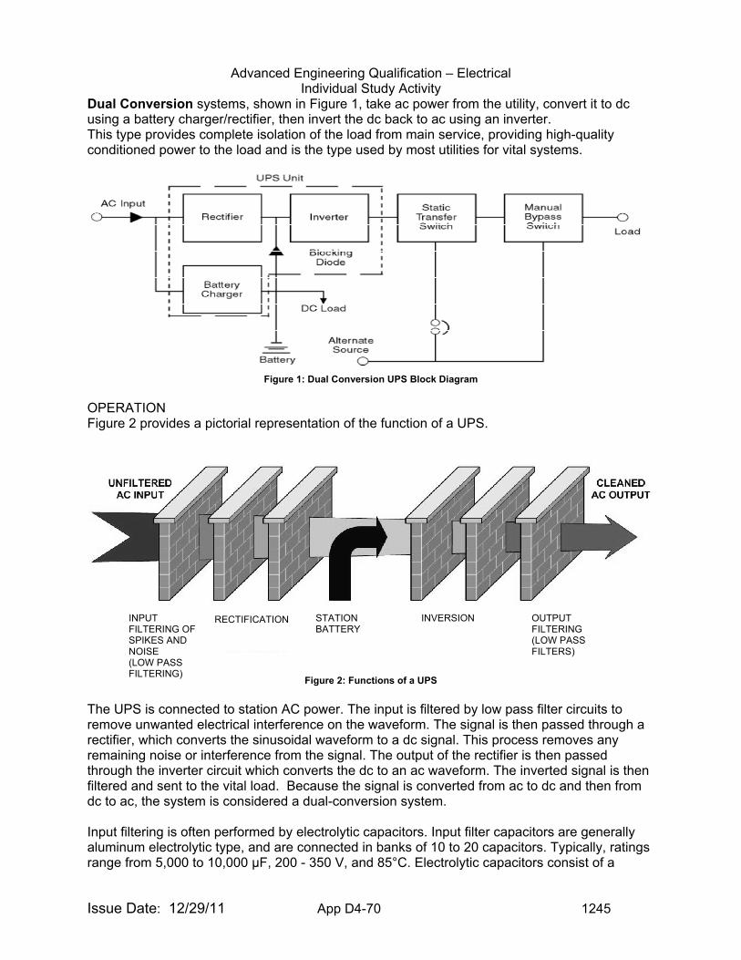
Advanced Engineering Qualification – Electrical Individual Study Activity
Issue Date: 12/29/11 App D4-70 1245
Dual Conversion systems, shown in Figure 1, take ac power from the utility, convert it to dc using a battery charger/rectifier, then invert the dc back to ac using an inverter. This type provides complete isolation of the load from main service, providing high-quality conditioned power to the load and is the type used by most utilities for vital systems.
Figure 1: Dual Conversion UPS Block Diagram
OPERATION Figure 2 provides a pictorial representation of the function of a UPS.
Figure 2: Functions of a UPS
The UPS is connected to station AC power. The input is filtered by low pass filter circuits to remove unwanted electrical interference on the waveform. The signal is then passed through a rectifier, which converts the sinusoidal waveform to a dc signal. This process removes any remaining noise or interference from the signal. The output of the rectifier is then passed through the inverter circuit which converts the dc to an ac waveform. The inverted signal is then filtered and sent to the vital load. Because the signal is converted from ac to dc and then from dc to ac, the system is considered a dual-conversion system. Input filtering is often performed by electrolytic capacitors. Input filter capacitors are generally aluminum electrolytic type, and are connected in banks of 10 to 20 capacitors. Typically, ratings range from 5,000 to 10,000 μF, 200 - 350 V, and 85°C. Electrolytic capacitors consist of a
STATION BATTERY
INPUT FILTERING OF SPIKES AND NOISE (LOW PASS FILTERING)
RECTIFICATION INVERSION OUTPUT FILTERING (LOW PASS FILTERS)
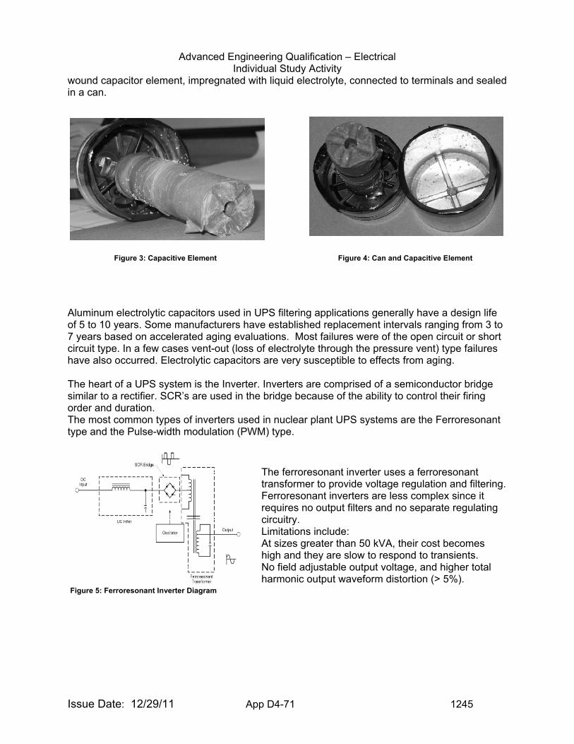
Advanced Engineering Qualification – Electrical Individual Study Activity
Issue Date: 12/29/11 App D4-71 1245
wound capacitor element, impregnated with liquid electrolyte, connected to terminals and sealed in a can.
Figure 3: Capacitive Element Figure 4: Can and Capacitive Element
Aluminum electrolytic capacitors used in UPS filtering applications generally have a design life of 5 to 10 years. Some manufacturers have established replacement intervals ranging from 3 to 7 years based on accelerated aging evaluations. Most failures were of the open circuit or short circuit type. In a few cases vent-out (loss of electrolyte through the pressure vent) type failures have also occurred. Electrolytic capacitors are very susceptible to effects from aging. The heart of a UPS system is the Inverter. Inverters are comprised of a semiconductor bridge similar to a rectifier. SCR’s are used in the bridge because of the ability to control their firing order and duration. The most common types of inverters used in nuclear plant UPS systems are the Ferroresonant type and the Pulse-width modulation (PWM) type.
Figure 5: Ferroresonant Inverter Diagram
The ferroresonant inverter uses a ferroresonant transformer to provide voltage regulation and filtering. Ferroresonant inverters are less complex since it requires no output filters and no separate regulating circuitry. Limitations include: At sizes greater than 50 kVA, their cost becomes high and they are slow to respond to transients. No field adjustable output voltage, and higher total harmonic output waveform distortion (> 5%).
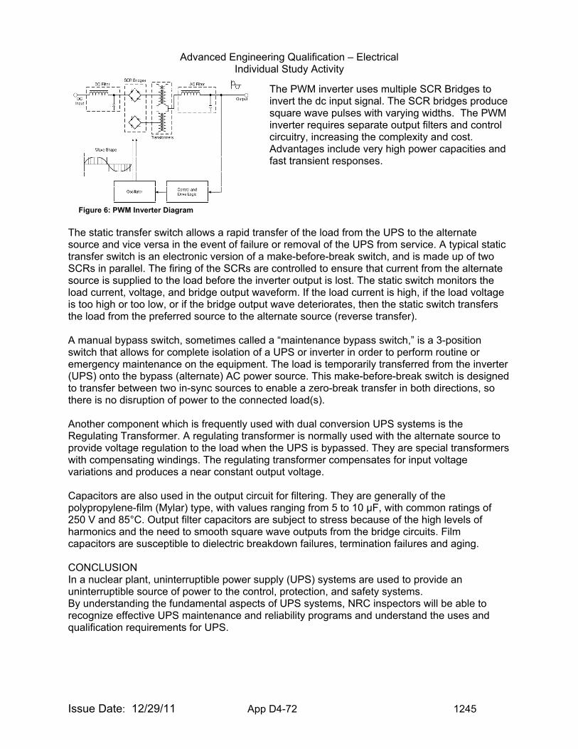
Advanced Engineering Qualification – Electrical Individual Study Activity
Issue Date: 12/29/11 App D4-72 1245
Figure 6: PWM Inverter Diagram
The static transfer switch allows a rapid transfer of the load from the UPS to the alternate source and vice versa in the event of failure or removal of the UPS from service. A typical static transfer switch is an electronic version of a make-before-break switch, and is made up of two SCRs in parallel. The firing of the SCRs are controlled to ensure that current from the alternate source is supplied to the load before the inverter output is lost. The static switch monitors the load current, voltage, and bridge output waveform. If the load current is high, if the load voltage is too high or too low, or if the bridge output wave deteriorates, then the static switch transfers the load from the preferred source to the alternate source (reverse transfer). A manual bypass switch, sometimes called a “maintenance bypass switch,” is a 3-position switch that allows for complete isolation of a UPS or inverter in order to perform routine or emergency maintenance on the equipment. The load is temporarily transferred from the inverter (UPS) onto the bypass (alternate) AC power source. This make-before-break switch is designed to transfer between two in-sync sources to enable a zero-break transfer in both directions, so there is no disruption of power to the connected load(s). Another component which is frequently used with dual conversion UPS systems is the Regulating Transformer. A regulating transformer is normally used with the alternate source to provide voltage regulation to the load when the UPS is bypassed. They are special transformers with compensating windings. The regulating transformer compensates for input voltage variations and produces a near constant output voltage. Capacitors are also used in the output circuit for filtering. They are generally of the polypropylene-film (Mylar) type, with values ranging from 5 to 10 μF, with common ratings of 250 V and 85°C. Output filter capacitors are subject to stress because of the high levels of harmonics and the need to smooth square wave outputs from the bridge circuits. Film capacitors are susceptible to dielectric breakdown failures, termination failures and aging. CONCLUSION In a nuclear plant, uninterruptible power supply (UPS) systems are used to provide an uninterruptible source of power to the control, protection, and safety systems. By understanding the fundamental aspects of UPS systems, NRC inspectors will be able to recognize effective UPS maintenance and reliability programs and understand the uses and qualification requirements for UPS.
The PWM inverter uses multiple SCR Bridges to invert the dc input signal. The SCR bridges produce square wave pulses with varying widths. The PWM inverter requires separate output filters and control circuitry, increasing the complexity and cost. Advantages include very high power capacities and fast transient responses.
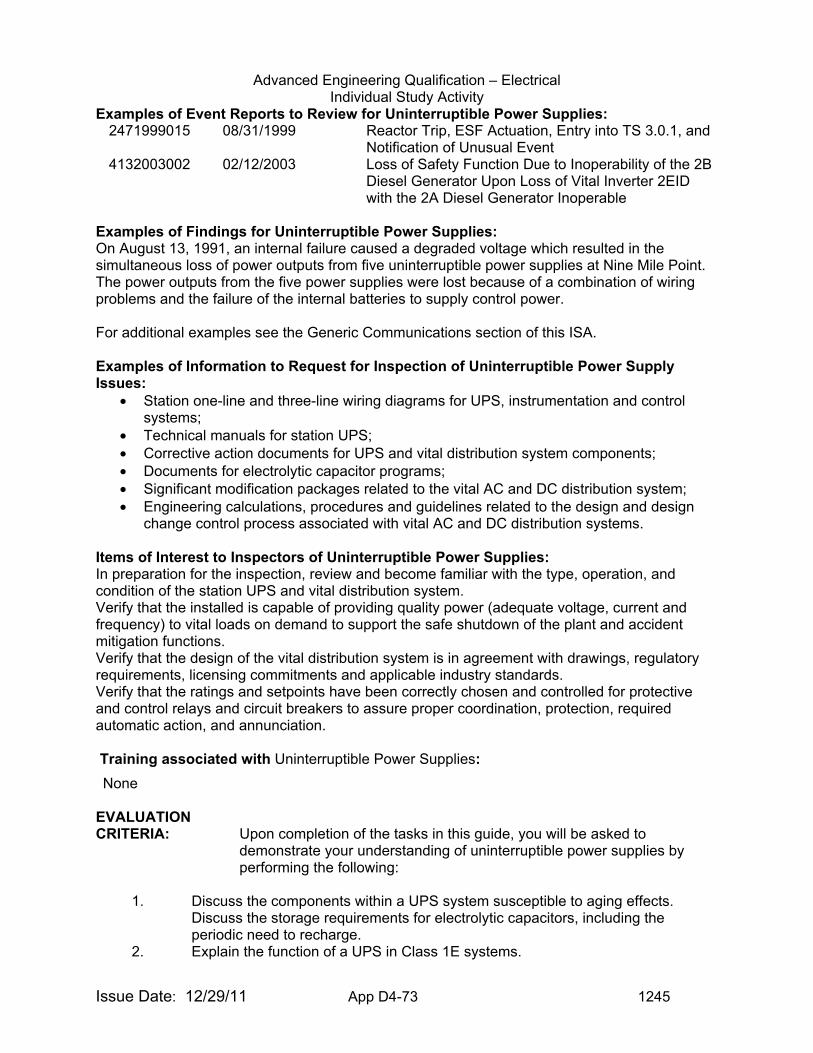
Advanced Engineering Qualification – Electrical Individual Study Activity
Issue Date: 12/29/11 App D4-73 1245
Examples of Event Reports to Review for Uninterruptible Power Supplies: 2471999015 08/31/1999 Reactor Trip, ESF Actuation, Entry into TS 3.0.1, and
Notification of Unusual Event 4132003002 02/12/2003 Loss of Safety Function Due to Inoperability of the 2B
Diesel Generator Upon Loss of Vital Inverter 2EID with the 2A Diesel Generator Inoperable
Examples of Findings for Uninterruptible Power Supplies: On August 13, 1991, an internal failure caused a degraded voltage which resulted in the simultaneous loss of power outputs from five uninterruptible power supplies at Nine Mile Point. The power outputs from the five power supplies were lost because of a combination of wiring problems and the failure of the internal batteries to supply control power. For additional examples see the Generic Communications section of this ISA. Examples of Information to Request for Inspection of Uninterruptible Power Supply Issues:
• Station one-line and three-line wiring diagrams for UPS, instrumentation and control systems;
• Technical manuals for station UPS; • Corrective action documents for UPS and vital distribution system components; • Documents for electrolytic capacitor programs; • Significant modification packages related to the vital AC and DC distribution system; • Engineering calculations, procedures and guidelines related to the design and design
change control process associated with vital AC and DC distribution systems. Items of Interest to Inspectors of Uninterruptible Power Supplies: In preparation for the inspection, review and become familiar with the type, operation, and condition of the station UPS and vital distribution system. Verify that the installed is capable of providing quality power (adequate voltage, current and frequency) to vital loads on demand to support the safe shutdown of the plant and accident mitigation functions. Verify that the design of the vital distribution system is in agreement with drawings, regulatory requirements, licensing commitments and applicable industry standards. Verify that the ratings and setpoints have been correctly chosen and controlled for protective and control relays and circuit breakers to assure proper coordination, protection, required automatic action, and annunciation.
Training associated with Uninterruptible Power Supplies:
EVALUATION CRITERIA: Upon completion of the tasks in this guide, you will be asked to
demonstrate your understanding of uninterruptible power supplies by performing the following:
1. Discuss the components within a UPS system susceptible to aging effects. Discuss the storage requirements for electrolytic capacitors, including the periodic need to recharge.
2. Explain the function of a UPS in Class 1E systems.
None
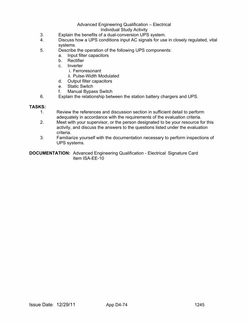
Advanced Engineering Qualification – Electrical Individual Study Activity
Issue Date: 12/29/11 App D4-74 1245
3. Explain the benefits of a dual-conversion UPS system. 4. Discuss how a UPS conditions input AC signals for use in closely regulated, vital
systems. 5. Describe the operation of the following UPS components:
a. Input filter capacitors b. Rectifier c. Inverter
i. Ferroresonant ii. Pulse-Width Modulated
d. Output filter capacitors e. Static Switch f. Manual Bypass Switch
6. Explain the relationship between the station battery chargers and UPS.
TASKS: 1. Review the references and discussion section in sufficient detail to perform
adequately in accordance with the requirements of the evaluation criteria. 2. Meet with your supervisor, or the person designated to be your resource for this
activity, and discuss the answers to the questions listed under the evaluation criteria.
3. Familiarize yourself with the documentation necessary to perform inspections of UPS systems.
DOCUMENTATION: Advanced Engineering Qualification - Electrical Signature Card
Item ISA-EE-10
Advanced Engineering Qualification – Electrical Individual Study Activity
Issue Date: 12/29/11 App D4-75 1245
TOPIC: (ISA-EE-11) Transformers PURPOSE: The purpose of this guide is to provide the inspector with some basic
concepts related to oil-filled power transformers. The level of detail associated with this Individual Study Assignment is not expected to instill more than a general familiarity with the standards, construction, testing and operation of large, oil-filled power transformers.
COMPETENCY AREA: INSPECTION LEVEL OF EFFORT: As determined by Branch Chief or supervisor REFERENCES: 1. IEEE Std C57.12.00 Institute for Electrical and Electronic Engineers Standard General
Requirements for Liquid-Immersed Distribution, Power, and Regulating Transformers
2. ANSI Std C57.12.10 American National Standard for Transformer Safety Requirements
3. IEEE Std C57.12.70 Institute for Electrical and Electronic Engineers Standard Terminal Markings and Connections for Distribution and Power Transformers
4. IEEE Std C57.12.80 Institute for Electrical and Electronic Engineers Standard Terminology for Power and Distribution Transformers
5. IEEE Std C57.12.90 Institute for Electrical and Electronic Engineers Standard Test Code for Liquid-Immersed Distribution, Power, and Regulating Transformers
6. IEEE Std C57.19.00 Institute for Electrical and Electronic Engineers Standard General Requirements and Test Procedure for Power Apparatus Bushings
7. IEEE Std C57.19.01 Institute for Electrical and Electronic Engineers Standard Performance Characteristics and Dimensions for Outdoor Apparatus Bushings
8. IEEE Std C57.19.100 Institute for Electrical and Electronic Engineers Guide for Application of Power Apparatus Bushings
9. IEEE Std C57.91 Institute for Electrical and Electronic Engineers Guide for Loading Mineral-Oil-Immersed Transformers
10. IEEE Std C57.93 Institute for Electrical and Electronic Engineers Guide for Installation of Liquid-Immersed Power Transformers
11. IEEE Std C57.98 Institute for Electrical and Electronic Engineers Guide for Transformer Impulse Tests
12. IEEE Std C57.100 Institute for Electrical and Electronic Engineers Standard Test Procedure for Thermal Evaluation of Liquid-Immersed Distribution and Power Transformers
Advanced Engineering Qualification – Electrical Individual Study Activity
Issue Date: 12/29/11 App D4-76 1245
13. IEEE Std C57.104 Institute for Electrical and Electronic Engineers Guide for the Interpretation of Gases Generated in Oil-Immersed Transformers
14. IEEE Std C57.131 Institute for Electrical and Electronic Engineers Standard Requirements for Load Tap Changers
15. IEEE Std C62.22 Institute for Electrical and Electronic Engineers Guide for the Application of Metal-Oxide Surge Arresters for Alternating-Current Systems
16. NFPA 805 Recommended Practice for Fire Protection for Electric Generating Plants and High Voltage Direct Current Converter Stations
Although not used in developing this ISA there are several other good references on transformers that are located on the United States Department of the Interior Bureau of Reclamation Website at http://www.usbr.gov/power/data/fist_pub.html/. These documents are:
17. Facilities Instructions, Standards, and Techniques (FIST) Volume 1–5, Permissible Loading of Oil-Immersed Transformers And Regulators
18. FIST Volume 3-2, Testing and Maintenance of High-Voltage Bushings
19. FIST Volume 3-9, Methods For Coordinating System Protective Equipment
20. FIST Volume 3-7, Painting of Transformers and Circuit Breakers
21. FIST Volume 3-23, Instrument Transformer Secondary Grounding
22. FIST 3-30, Transformer Maintenance
23. FIST Volume 3-31, Transformer Diagnostics
24. FIST Volume 3-32, Transformer Fire Protection
DISCUSSION: Large power transformers (LPTs) are the very heart and soul of the electric system. Generation facilities can produce all of the steam that they are physically able to use in their turbines in accordance with their ratings, but if there is no transformer to link the plant to the grid, then the generating plant cannot export it’s product to the marketplace. The loss of a critical unit on a transmission system can also cripple the grid. Thus, LPTs are critical to the proper functionality of the entire system. Transformers are highly labor intensive components that require long periods of time to manufacture. In general terms, a large unit can take anywhere from 26 to 80 weeks from placement of order to delivery and installation on the pad. These long lead times serve to acutely compound the criticality of LPTs. Fundamentals The Danish physicist Hans Christian Oersted revealed, circa 1820, that an electric current flowing in a wire could create a magnetic effect on a compass needle. In 1831, the English scientist Michael Faraday found that a wire, when given motion in a magnetic field, will
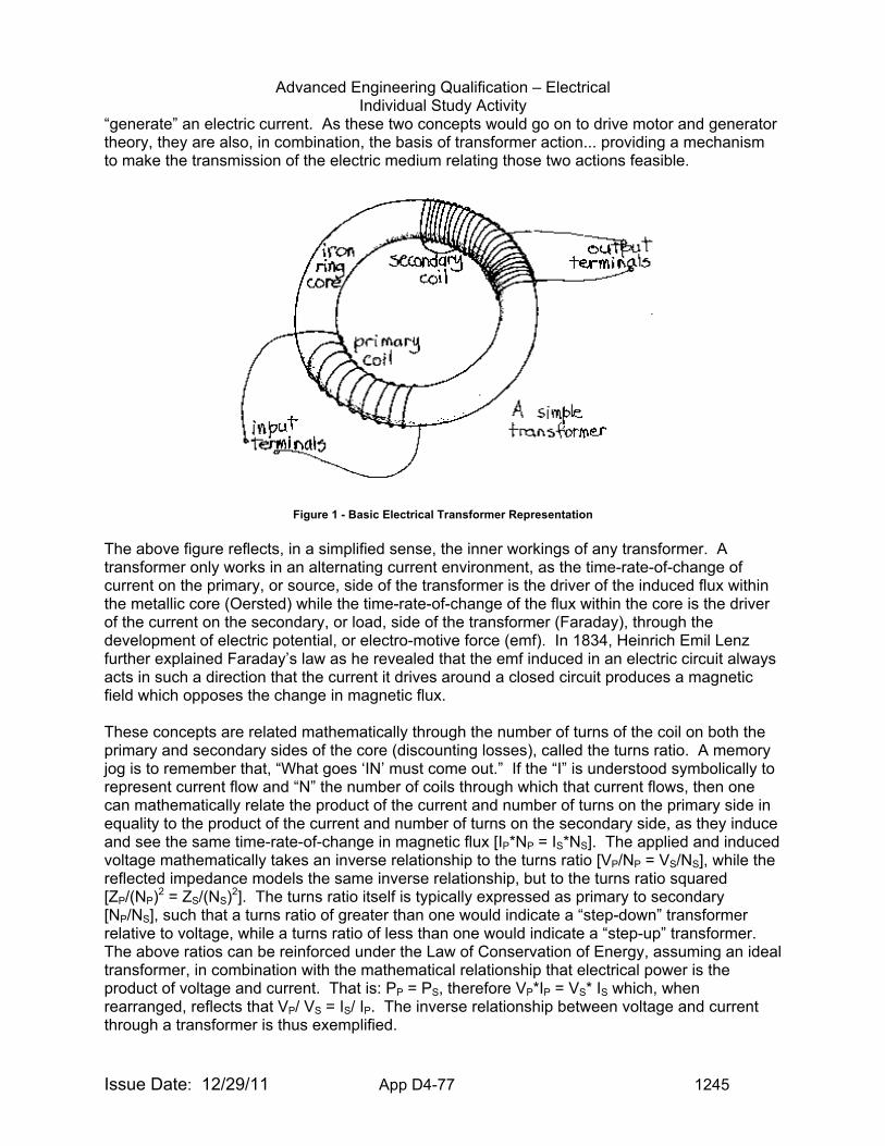
Advanced Engineering Qualification – Electrical Individual Study Activity
Issue Date: 12/29/11 App D4-77 1245
“generate” an electric current. As these two concepts would go on to drive motor and generator theory, they are also, in combination, the basis of transformer action... providing a mechanism to make the transmission of the electric medium relating those two actions feasible.
Figure 1 - Basic Electrical Transformer Representation
The above figure reflects, in a simplified sense, the inner workings of any transformer. A transformer only works in an alternating current environment, as the time-rate-of-change of current on the primary, or source, side of the transformer is the driver of the induced flux within the metallic core (Oersted) while the time-rate-of-change of the flux within the core is the driver of the current on the secondary, or load, side of the transformer (Faraday), through the development of electric potential, or electro-motive force (emf). In 1834, Heinrich Emil Lenz further explained Faraday’s law as he revealed that the emf induced in an electric circuit always acts in such a direction that the current it drives around a closed circuit produces a magnetic field which opposes the change in magnetic flux. These concepts are related mathematically through the number of turns of the coil on both the primary and secondary sides of the core (discounting losses), called the turns ratio. A memory jog is to remember that, “What goes ‘IN’ must come out.” If the “I” is understood symbolically to represent current flow and “N” the number of coils through which that current flows, then one can mathematically relate the product of the current and number of turns on the primary side in equality to the product of the current and number of turns on the secondary side, as they induce and see the same time-rate-of-change in magnetic flux [IP*NP = IS*NS]. The applied and induced voltage mathematically takes an inverse relationship to the turns ratio [VP/NP = VS/NS], while the reflected impedance models the same inverse relationship, but to the turns ratio squared [ZP/(NP)2 = ZS/(NS)2]. The turns ratio itself is typically expressed as primary to secondary [NP/NS], such that a turns ratio of greater than one would indicate a “step-down” transformer relative to voltage, while a turns ratio of less than one would indicate a “step-up” transformer. The above ratios can be reinforced under the Law of Conservation of Energy, assuming an ideal transformer, in combination with the mathematical relationship that electrical power is the product of voltage and current. That is: PP = PS, therefore VP*IP = VS* IS which, when rearranged, reflects that VP/ VS = IS/ IP. The inverse relationship between voltage and current through a transformer is thus exemplified.
Advanced Engineering Qualification – Electrical Individual Study Activity
Issue Date: 12/29/11 App D4-78 1245
Construction There are four principal categories of power transformers:
Distribution 5 – 2,500 KVA ≤ 46 KV Small Power 1,500 – 10,000 KVA ≤ 69 KV Medium Power 10,000 – 60,000 KVA ≤ 230 KV Large Power > 60,000 KVA Up to 765 KV
The LPT and medium power transformer (MPT) share many fundamental commonalities, and are the transformers to which this ISA is oriented. Their commonalities are driven around their construction, operation, and cooling. This triad, it so happens, represents the building blocks of this ISA. The construction of MPTs and LPTs is relatively more complex than the simplified device reflected in Figure 1. However, the device is not so complex as to completely obscure its basic components - if one can get past the fact that the high voltage windings envelope the low voltage windings around a common “laminated” metal core. Figure 2 provides a cutaway view of a typical oil-cooled power transformer of the MPT/LPT variety. Transformers can be constructed as a three-phase device, providing for a smaller relative footprint and simplified station architecture, or a single-phase device, offering the flexibility of providing a phase spare by purchasing and configuring for a fourth transformer in the layout. Additionally, within the transformer itself, the core and windings may take a core-form or a shell-form construction. Figure 2 reflects a three-phased core-form transformer. This would be the least expensive option for a power transformer installation, though a problem with a single phase necessarily implicates the entire transformer. When combined with the long lead times mentioned earlier, this could provide economic justification for a single-phase transformer procurement. The benefit derived from the additional cost of a shell-form transformer is increased through-fault performance.
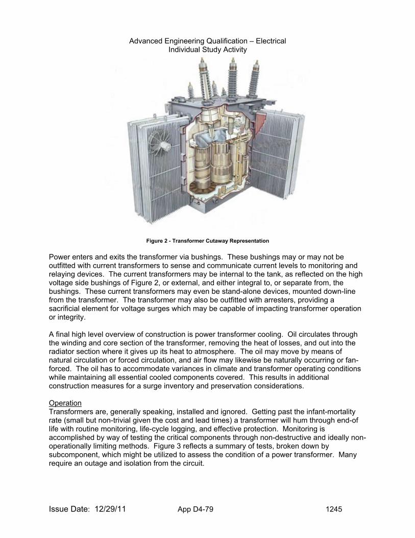
Advanced Engineering Qualification – Electrical Individual Study Activity
Issue Date: 12/29/11 App D4-79 1245
Figure 2 - Transformer Cutaway Representation
Power enters and exits the transformer via bushings. These bushings may or may not be outfitted with current transformers to sense and communicate current levels to monitoring and relaying devices. The current transformers may be internal to the tank, as reflected on the high voltage side bushings of Figure 2, or external, and either integral to, or separate from, the bushings. These current transformers may even be stand-alone devices, mounted down-line from the transformer. The transformer may also be outfitted with arresters, providing a sacrificial element for voltage surges which may be capable of impacting transformer operation or integrity. A final high level overview of construction is power transformer cooling. Oil circulates through the winding and core section of the transformer, removing the heat of losses, and out into the radiator section where it gives up its heat to atmosphere. The oil may move by means of natural circulation or forced circulation, and air flow may likewise be naturally occurring or fan-forced. The oil has to accommodate variances in climate and transformer operating conditions while maintaining all essential cooled components covered. This results in additional construction measures for a surge inventory and preservation considerations. Operation Transformers are, generally speaking, installed and ignored. Getting past the infant-mortality rate (small but non-trivial given the cost and lead times) a transformer will hum through end-of life with routine monitoring, life-cycle logging, and effective protection. Monitoring is accomplished by way of testing the critical components through non-destructive and ideally non-operationally limiting methods. Figure 3 reflects a summary of tests, broken down by subcomponent, which might be utilized to assess the condition of a power transformer. Many require an outage and isolation from the circuit.
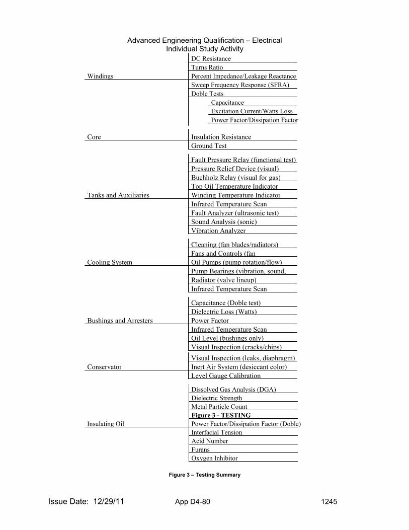
Advanced Engineering Qualification – Electrical Individual Study Activity
Issue Date: 12/29/11 App D4-80 1245
Figure 3 – Testing Summary
Power Factor/Dissipation Factor (Doble)
Dissolved Gas Analysis (DGA) Dielectric Strength Metal Particle Count Figure 3 - TESTING
Interfacial Tension Acid Number Furans Oxygen Inhibitor
Insulating Oil
Visual Inspection (leaks, diaphragm) Inert Air System (desiccant color)Conservator Level Gauge Calibration
Capacitance (Doble test)Dielectric Loss (Watts)Power FactorInfrared Temperature ScanOil Level (bushings only)Visual Inspection (cracks/chips)
Bushings and Arresters
Cleaning (fan blades/radiators)Fans and Controls (fan Oil Pumps (pump rotation/flow)Pump Bearings (vibration, sound, Radiator (valve lineup)Infrared Temperature Scan
Cooling System
Fault Pressure Relay (functional test) Pressure Relief Device (visual)Buchholz Relay (visual for gas)Top Oil Temperature IndicatorWinding Temperature IndicatorInfrared Temperature ScanFault Analyzer (ultrasonic test)Sound Analysis (sonic)Vibration Analyzer
Tanks and Auxiliaries
Insulation ResistanceGround Test
Core
DC Resistance Turns Ratio Percent Impedance/Leakage Reactance Sweep Frequency Response (SFRA) Doble Tests
Capacitance Excitation Current/Watts Loss Power Factor/Dissipation Factor
Windings
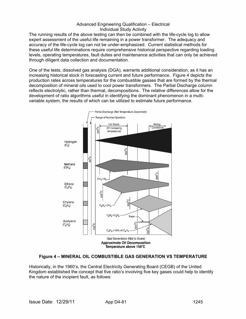
Advanced Engineering Qualification – Electrical Individual Study Activity
Issue Date: 12/29/11 App D4-81 1245
The running results of the above testing can then be combined with the life-cycle log to allow expert assessment of the useful life remaining in a power transformer. The adequacy and accuracy of the life-cycle log can not be under-emphasized. Current statistical methods for these useful life determinations require comprehensive historical perspective regarding loading levels, operating temperatures, fault duties and maintenance activities that can only be achieved through diligent data collection and documentation. One of the tests, dissolved gas analysis (DGA), warrants additional consideration, as it has an increasing historical stock in forecasting current and future performance. Figure 4 depicts the production rates across temperatures for the combustible gasses that are formed by the thermal decomposition of mineral oils used to cool power transformers. The Partial Discharge column reflects electrolytic, rather than thermal, decompositions. The relative differences allow for the development of ratio algorithms useful in identifying the dominant phenomenon in a multi-variable system, the results of which can be utilized to estimate future performance.
Figure 4 – MINERAL OIL COMBUSTIBLE GAS GENERATION VS TEMPERATURE Historically, in the 1960’s, the Central Electricity Generating Board (CEGB) of the United Kingdom established the concept that five ratio’s involving five key gases could help to identify the nature of the incipient fault, as follows:
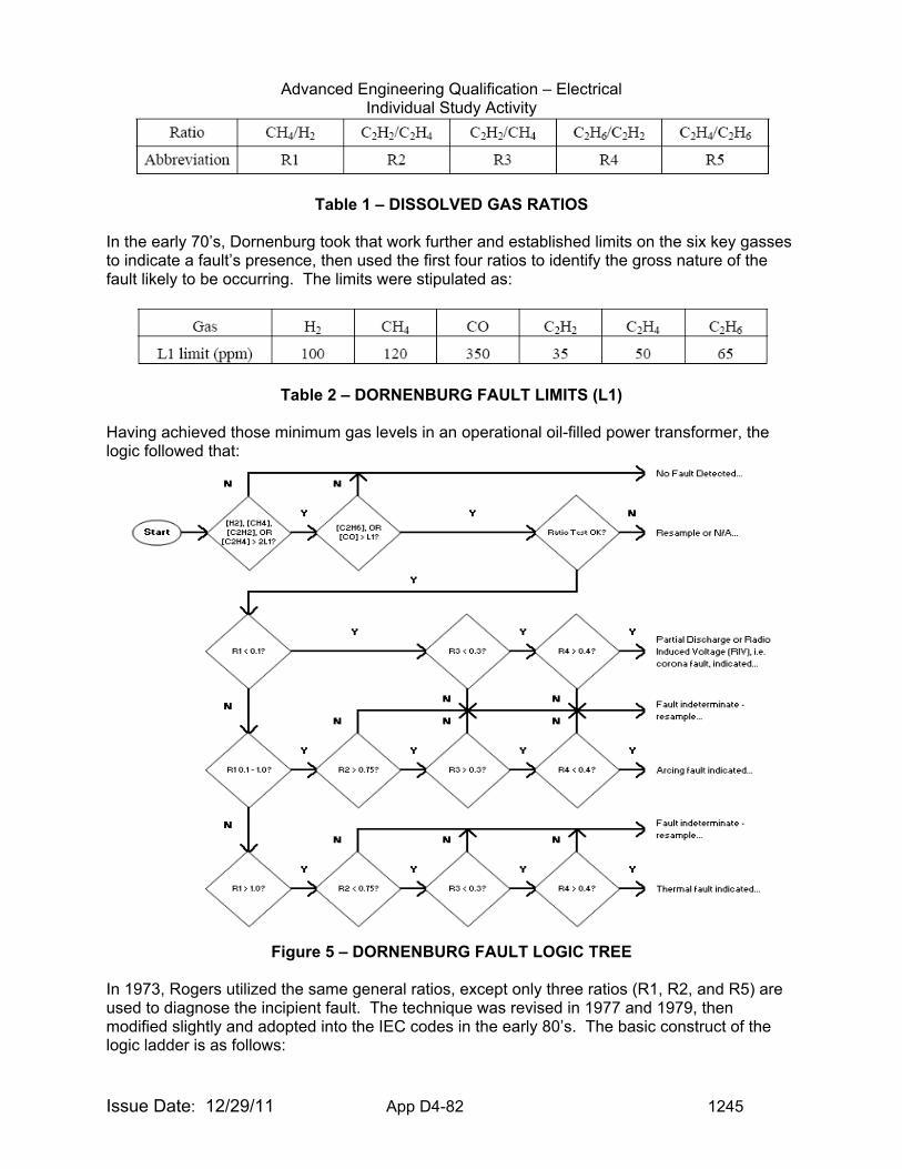
Advanced Engineering Qualification – Electrical Individual Study Activity
Issue Date: 12/29/11 App D4-82 1245
Table 1 – DISSOLVED GAS RATIOS
In the early 70’s, Dornenburg took that work further and established limits on the six key gasses to indicate a fault’s presence, then used the first four ratios to identify the gross nature of the fault likely to be occurring. The limits were stipulated as:
Table 2 – DORNENBURG FAULT LIMITS (L1)
Having achieved those minimum gas levels in an operational oil-filled power transformer, the logic followed that:
Figure 5 – DORNENBURG FAULT LOGIC TREE
In 1973, Rogers utilized the same general ratios, except only three ratios (R1, R2, and R5) are used to diagnose the incipient fault. The technique was revised in 1977 and 1979, then modified slightly and adopted into the IEC codes in the early 80’s. The basic construct of the logic ladder is as follows:
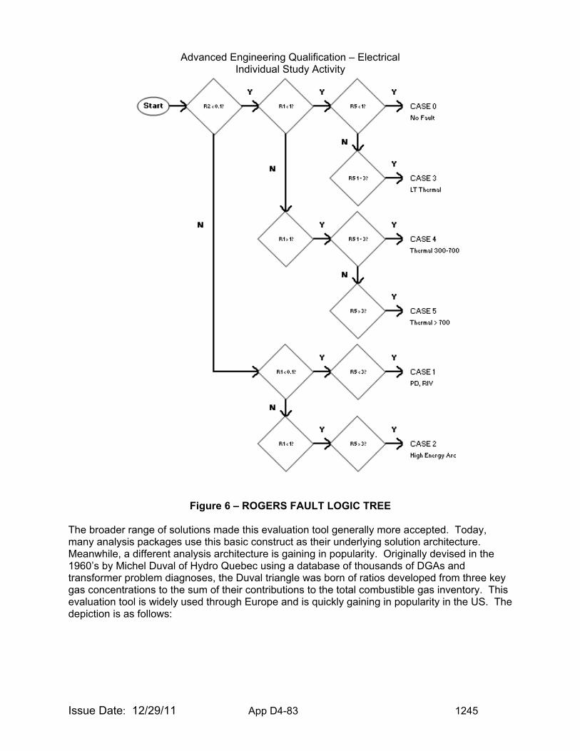
Advanced Engineering Qualification – Electrical Individual Study Activity
Issue Date: 12/29/11 App D4-83 1245
Figure 6 – ROGERS FAULT LOGIC TREE The broader range of solutions made this evaluation tool generally more accepted. Today, many analysis packages use this basic construct as their underlying solution architecture. Meanwhile, a different analysis architecture is gaining in popularity. Originally devised in the 1960’s by Michel Duval of Hydro Quebec using a database of thousands of DGAs and transformer problem diagnoses, the Duval triangle was born of ratios developed from three key gas concentrations to the sum of their contributions to the total combustible gas inventory. This evaluation tool is widely used through Europe and is quickly gaining in popularity in the US. The depiction is as follows:
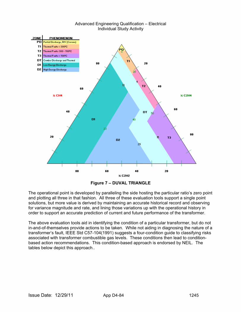
Advanced Engineering Qualification – Electrical Individual Study Activity
Issue Date: 12/29/11 App D4-84 1245
Figure 7 – DUVAL TRIANGLE
The operational point is developed by paralleling the side hosting the particular ratio’s zero point and plotting all three in that fashion. All three of these evaluation tools support a single point solutions, but more value is derived by maintaining an accurate historical record and observing for variance magnitude and rate, and lining those variations up with the operational history in order to support an accurate prediction of current and future performance of the transformer. The above evaluation tools aid in identifying the condition of a particular transformer, but do not in-and-of-themselves provide actions to be taken. While not aiding in diagnosing the nature of a transformer’s fault, IEEE Std C57-104(1991) suggests a four-condition guide to classifying risks associated with transformer combustible gas levels. These conditions then lead to condition-based action recommendations. This condition-based approach is endorsed by NEIL. The tables below depict this approach..
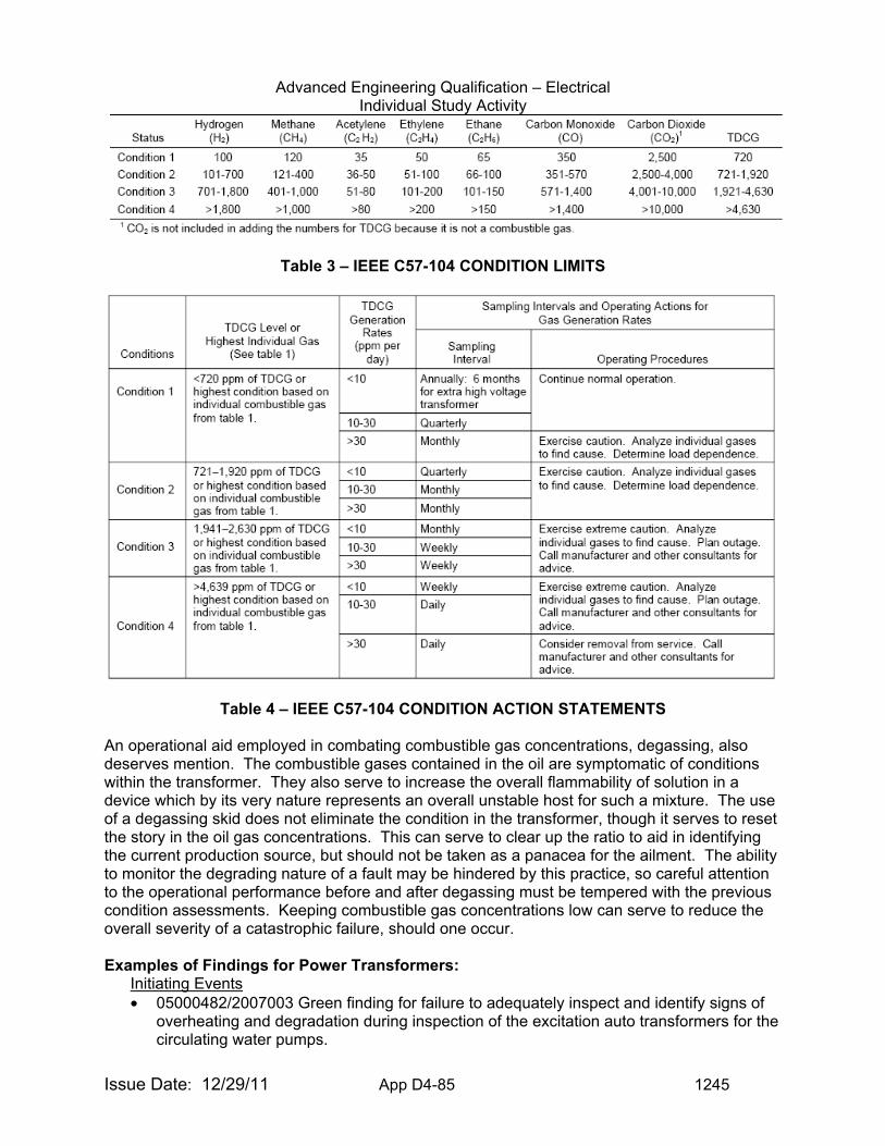
Advanced Engineering Qualification – Electrical Individual Study Activity
Issue Date: 12/29/11 App D4-85 1245
Table 3 – IEEE C57-104 CONDITION LIMITS
Table 4 – IEEE C57-104 CONDITION ACTION STATEMENTS An operational aid employed in combating combustible gas concentrations, degassing, also deserves mention. The combustible gases contained in the oil are symptomatic of conditions within the transformer. They also serve to increase the overall flammability of solution in a device which by its very nature represents an overall unstable host for such a mixture. The use of a degassing skid does not eliminate the condition in the transformer, though it serves to reset the story in the oil gas concentrations. This can serve to clear up the ratio to aid in identifying the current production source, but should not be taken as a panacea for the ailment. The ability to monitor the degrading nature of a fault may be hindered by this practice, so careful attention to the operational performance before and after degassing must be tempered with the previous condition assessments. Keeping combustible gas concentrations low can serve to reduce the overall severity of a catastrophic failure, should one occur. Examples of Findings for Power Transformers:
Initiating Events • 05000482/2007003 Green finding for failure to adequately inspect and identify signs of
overheating and degradation during inspection of the excitation auto transformers for the circulating water pumps.
Advanced Engineering Qualification – Electrical Individual Study Activity
Issue Date: 12/29/11 App D4-86 1245
• 05000286/2007003 Green finding for failure to identify in the corrective action program an adverse condition associated with the “B” phase high voltage bushing on a main transformer discovered during testing.
• 05000305/2007002 Green NCV for failure to control loose materials near the plant main power transformer in accordance with plant procedures in response to a high wind advisory.
• 05000255/2006009 Green NCV for failure to evaluate the potentially adverse effects that a modification to add an automatic load tap changer to the startup transformer would have on the independence of the two circuits from the offsite power supply and on the fast transfer capabilities.
• 05000346/2006004 Green finding for failure to control loose materials located adjacent to the switchyard and under power lines from the switchyard to the station’s large power transformers against high winds.
• 05000266(301)/2006004 Green finding for failure to control loose materials in the protected area in the vicinity of the main and auxiliary transformers against high winds.
• 05000254/2006005 Green finding for failure to follow main power transformer design specifications calling for the installation of electrical conduit bushings at junction boxes for associated relaying circuits, resulting in a turbine trip and reactor scram.
• 05000305/2006002 Green finding for failure to control loose materials within the protected area south of the transformer bays in response to adverse weather conditions.
• 05000305/2005008 Green finding for failure to control loose material in the protected area and the substation adjacent to the auxiliary transformers against high winds.
• 05000282(306)/2005004 Green finding for failure to identify discrepant conditions during the performance of a plant surveillance procedure for identifying and removing potential missile hazards which jeopardized the 2M, 2RX, and 2RY transformers.
• 05000388/2005003 Green finding for failure to take adequate corrective actions to address single point vulnerability for a total loss of transformer cooling requiring a manual reactor scram.
• 05000331/2005003 Green finding for failure to control materials in the areas adjacent to the main, startup, and standby transformers and the switchyard against high winds.
Mitigating Systems • 05000275/2005005 Green NCV for failure of maintenance personnel to adequately
assess and manage the risk associated with maintenance on a startup transformer to preclude interruption of startup power to the plant
• 05000275/2005004 Green NCV for failure to adequately assess and manage the risk associated with maintenance on a startup transformer to preclude challenging the opposite startup transformer’s operations as a result of relay maintenance.
• 05000269(270,287)/2005003 Green NCV for failure to take adequate corrective actions related to the timeliness of identification of a failed electrical contactor supplying one train of power to the Keowanee Hydro Unit main step-up transformer cooling system, resulting in a reduction in reliability of the overhead offsite power supply.
Miscellaneous • 05000255/2006009 Green NCV for failure to analyze past operability and submit a
licensee event report when the startup transformer tap changer control was found to be non-operational.
Recent LERs Related to Transformers:
• 2612007001 – 05/15/2007 – Reactor Trip due to a Loose Wire in the Main Transformer
Advanced Engineering Qualification – Electrical Individual Study Activity
Issue Date: 12/29/11 App D4-87 1245
Monitoring Circuitry • 2752007001 – 05/12/2007 – Emergency Diesel Generator Auto-start on Loss of Offsite
230kV Startup Power • 4582007002 – 05/04/2007 – Unplanned Manual Reactor Scram Due to Loss of Cooling
on No. 2 Main Transformer • 2862007002 – 04/06/2007 – Automatic Reactor Trip Due to a Turbine-Generator Trip
Caused by a Fault on the 31 Main Transformer Phase B High Voltage Bushing • 3392007002 – 03/07/2007 – Automatic Start of 2H EDG on Loss of B Reserve Station
Service Transformer Due To Cable Fault • 2552007001 – 01/04/2007 – Failure to Perform Offsite Power Source Check
Examples of Information to Request for Inspection of Power Transformer Issues: For any inspection to be successful, the inspector must request the right information in order to evaluate whether the licensee is correctly interpreting and applying requirements, industry standards, lessons learned and industry best practices. The following examples may be useful in requesting licensee information.
• Maintenance procedures for transformers. • Maintenance procedures involving voltage regulators, bushings and arrestors. • Purchase specifications, vendor documentation and receipt inspection documentation for
transformers. • Sizing of transformers for applications. Has any loading been added or removed. • Graphical loading summary. • Through-fault summary. • History of failures of transformers. • Dissolved-gas analysis (DGA) results for last 3 years or last 5 samples (depending upon
periodicity) and any trend evaluations performed. • Thermography or sound-spectropy reports for last 3 years or last 5 samples (depending
upon periodicity – and to include baseline) and any trend evaluations performed. • Power factor and insulation resistance results for last 3 years or last 5 samples
(depending upon periodicity) and any trend evaluations performed. • Frequency response analysis results for last 3 years or last 5 samples (depending upon
periodicity – and to include baseline) and any trend evaluations performed. • Maintenance Rule documentation involving transformers.
Transformer Items of Interest to Inspectors: Power transformers play a vital role in the safe operation of nuclear power plants relative to both incoming power for safe shutdown and outgoing power relative to initiating events. Problems may be found in several areas including programmatic, procedural, and maintenance. Each area should be reviewed for potential weaknesses involving circuit breaker operation, overhaul, and maintenance. Training associated with Power Transformers: Waukesha “Transformer Concepts and Applications” Seminar
http://www.waukeshaelectric.com/seminars.html
Doble “Life of a Transformer” Seminar http://www.doble.com/events/all.html/view/100 ABB Various Training Courses http://www.abb.com/ EVALUATION CRITERIA: Upon completion of the tasks in this guide, you will be asked to demonstrate
your understanding of power transformers by performing the following:
Advanced Engineering Qualification – Electrical Individual Study Activity
Issue Date: 12/29/11 App D4-88 1245
1. Identify the principal components associated with large oil-filled power transformers. 2. List some of the testing which is conducted on those components previously identified. 3. Describe and state the relative advantages/disadvantages associated with shell and
core form transformers. 4. Identify the mechanisms of oil preservation (Ref. 2). 5. Explain the operations of load tap changers and identify the inherent operational
considerations associated with these devices (Ref. 5, 14). 6. Explain the role of the transformer bushings and describe their construction (Ref. 6, 7,
8). 7. Describe the principles associated with transformer differential relaying protection,
including the necessary input considerations. 8. Identify the principal thermal gases generated by energy source/temperature (Ref. 13). 9. State the considerations for effective dissolved gas analysis (DGA) (Ref. 13). 10. Name and outline three DGA analysis techniques, to include the indicated faults (Ref.
13). 11. Identify several forms of on-board instrumentation which may be available for routine
observation (Ref. 2). 12. Describe the fire protection recommendations for power transformers as identified in
the current industry guidance (Ref. 16).
TASKS: 1. Read the references in sufficient detail to perform adequately in accordance with the
requirements of the evaluation criteria.
2. Meet with your supervisor, or the person designated to be your resource for this activity, and discuss the answers to the questions listed under the evaluation criteria.
3. Familiarize yourself with the inspection resources listed under the Operational Experience website.
4. Familiarize yourself with the documentation necessary to perform inspections of power transformers.
DOCUMENTATION: Advanced Engineering Qualification – Electrical Signature Card Item ISA-EE-11
Advanced Engineering Qualification – Electrical Individual Study Activity
Issue Date: 12/29/11 App D4-89 1245
TOPIC: (ISA-EE-12) Cables PURPOSE: The purpose of this activity is to provide the inspector with some basic
concepts related to power and control cables used in nuclear power plants. The level of detail associated with this Individual Study Assignment is not expected to instill more than a general familiarity with the standards, construction, testing and operation of power and control cables.
COMPETENCY AREA: INSPECTION LEVEL OF EFFORT: As determined by Branch Chief or supervisor. REFERENCES:
1. IEEE Std 141 IEEE Recommended Practice for Electric Power Distribution for
Industrial Plants (Red Book) 2. NEMA WC 74/
ICEA S-93-639 5-46kv Shielded Power Cable for Use in the Transmission And Distribution of Electric Energy
3. IEEE Std 383 IEEE Standard for Qualifying Class 1E Electric Cables and Field Splices for Nuclear Power Generating Stations
4. IEEE Std 835 IEEE Standard Power Cable Ampacity Tables 5. IEEE Std 422 IEEE Guide for the Design and Installation of Cable Systems In
Power Generating Stations 6. IEEE Std 690 IEEE Standard for the Design and Installation of Cable Systems
for Class 1E Circuits in Nuclear Power Generating Stations 7. Regulatory Guide 1.131 Qualification Tests Of Electric Cables, Field Splices, and
Connections For Light-Water-Cooled Nuclear Power Plants 8. Regulatory Guide 1.211 Qualification of Safety-Related Cables and Field Splices for
Nuclear Power Plants 9. IEEE Std 848 IEEE Standard Procedure for the Determination of the Ampacity
Derating of Fire-Protected Cables 10. IEEE Std 1205 IEEE Guide for Assessing, Monitoring, and Mitigating Aging
Effects on Class 1E Equipment Used in Nuclear Power Generating Stations
Additional References The references listed here are not required for completion of this individual study activity. They are provided as additional reference material. IEEE Std 775 IEEE Guide for Designing Multi-Stress Aging Tests of Electrical Insulation
in a Radiation Environment IEEE Std 1064 IEEE Guide for Multi-Factor Stress Functional Testing of Electrical
Insulation Systems IEEE Std 1202 IEEE Standard for Flame Testing of Cables for Use in Cable Tray in
Industrial and Commercial Occupancies
Advanced Engineering Qualification – Electrical Individual Study Activity
Issue Date: 12/29/11 App D4-90 1245
NEMA WC 7/ICEA S-66-524 Cross Linked Thermosetting Polyethylene Insulated Wire and Cable for the Transmission and Distribution of Electrical Energy
NEMA WC 8/ICEA S-68-516 Ethylene-Propylene-Rubber-Insulated Wire and Cable for the Transmission and Distribution of Electrical Energy
NEMA WC 51 ANSI/ICEA P-54-440
Ampacities of Cables Installed in Cable Trays
NEMA WC 70/ ICEA S-95-658 Standard for Non-shielded Power Cables Rated 2000 Volts or Less for the Distribution of Electrical Energy
NFPA 262-2002 Standard Method of Test for Flame Travel and Smoke of Wires and Cables for Use in Air Handling Spaces
Okonite - Bulletin EHB-81 Engineering Data - Copper and Aluminum Conductor Electric Cables
NRC Generic Communications on Cables GL 2007-01 Inaccessible or Underground Power Cable Failures That Disable
Accident Mitigation Systems or cause Plant Transients Information Notice 84-68 Potential Deficiency in Improperly Rated Field Wiring to Solenoid
Valves Information Notice 86-49 Age/Environment Induced Electrical Cable Failures Information Notice 92-01 Cable Damage Caused By Inadequate Cable Installation
Procedures And Controls Information Notice 02-012 Submerged Safety-Related Electrical Cables Information Notice 98-021 Potential Deficiency of Electrical Cable/Connection Systems NUREG/CR 2377 Test and Criteria for Fire Protection of Cable Penetrations NUREG/CR 2927 Nuclear Power Plant Electrical Cable Damageability Experiments NUREG/CR 4700 Essential Elements of an Electric Cable Condition Monitoring
Program
Advanced Engineering Qualification – Electrical Individual Study Activity
Issue Date: 12/29/11 App D4-91 1245
Common Cable Acronyms AEIC Association of Edison Illuminating Companies AWG American Wire Gauge, CIC Cable in Conduit for buried distribution systems CSPE Chlorosulfonated Polyethylene compound ICEA Insulated Cable Engineers Association (formerly IPCEA). IEC International Electrotechnical Commission NEMA National Electrical Manufacturers Association NFPA National Fire Protection Association EPR Ethylene Propylene Rubber insulating compound ETFE Modified Ethylene Tetrofluoroethylene compound FEP Fluorinated Ethylene Propylene insulation and jacket compound FPL Power limited Fire Protective Signal Cable (NEC Art. 760). FRMR Flame Retardant, Moisture Retardant kcmil A unit of conductor area in thousands of circular mils. (Formerly MCM) LCS Longitudinal Corrugated ShieldMC Metal Clad mil 0.001 inch MV Medium Voltage NEC National Electrical CodePVC Polyvinyl Chloride TFN NEC conductor type designation for PVC insulated nylon jacketed conductors in
sizes #18 and 16 AWG for use in dry locationsTHHN NEC conductor type designation for PVC insulated nylon jacketed conductors
for use in dry locationsTHWN NEC conductor type designation for PVC insulated nylon jacketed conductors
for use in wet or dry locations.TR Triad TW Twisted pair or twisted triadUL Underwriters Laboratories.USE Underground Service Entrance cable.XLPE Cross-linked PolyethyleneXLPO Cross-linked Polyolefin
Advanced Engineering Qualification – Electrical Individual Study Activity
Issue Date: 12/29/11 App D4-92 1245
DISCUSSION: Electric cables are one of the most important components in a nuclear plant. Cables provide the paths for power flow needed to operate safety-related equipment and to transmit signals to and from the various controllers used to perform safety operations in the plant. In spite of their importance, in the past cables typically received little attention because they are considered passive, long-lived components that have proven to be very reliable over the years. A. Cable Definitions and A Brief History A power cable is an assembly of two or more electrical conductors, usually held together with an overall sheath. The assembly is used for transmission of electrical power. Power cables may be installed as permanent wiring within buildings, buried in the ground, run overhead, or exposed in cable trays. Many types of electric cable are used throughout the electric power industry. In nuclear power plants, electric cables are used for the transmission of power, communication, and control signals and data. Cable is generally designed for a specific application. The design process for cables includes the selection of conductor, insulation, shield, jacket, and armor material and the determination of the size of the conductor required for the anticipated service requirements. Because cables are designed for a particular application, interchanging different types of cables for different applications are normally not permitted. Early telegraph systems used the first forms of electrical cabling, transmitting small amounts of power. Gutta-percha insulation used on the first submarine cables was unsuitable for building wiring use since it deteriorated rapidly when exposed to air. The first power distribution system developed by Thomas Edison in 1882 in New York City used copper rods, wrapped in jute and placed in rigid pipes filled with a bituminous compound. Although vulcanized rubber had been patented by Charles Goodyear in 1844, it was not applied to cable insulation until the 1880s, when it was used for lighting circuits. Rubber-insulated cable was used for 11,000 volt circuits in 1897 installed for the Niagara Falls power project. Oil-impregnated paper-insulated high voltage cables were commercially practical by 1895. During World War II several varieties of synthetic rubber and polyethylene insulation were applied to cables. B. Cable Types
1. Power Cables: Power cables supply power to plant auxiliary system devices such as motors, heaters, chargers, and transformers. It has been traditional practice to describe cables in categories of low-voltage (LV.), medium-voltage (MV), high-voltage (HV), extra-high-voltage (EHV) and ultra-high-voltage (UHV). However, the boundaries have never been very precise, because they vary between different countries, among different groups of engineers. ANSI/NEMA C84.1 broadly defines system voltage classes. Low voltage (LV) power cable is used for systems operated at 600 V or less; medium voltage (MV) power cable is used for systems operated at 1001 to 35,000 V. 1/C, 3/C and triplex are typical power cable construction.
2. Lighting Wire and cable: These terms refer to power cables feeding lighting fixtures and ballasts. It is normally purchased as a single, solid-copper conductor and run in conduit. An alternate construction types normally preferred for lighting wire is multi-conductor cable ( two, three, or five or more as needed).
3. Control Cable: Normally rated at 600V minimum, control cables are those applied to relatively low current level or used for intermittent operations to change operating status of a utilization device of the plant auxiliary system. They interconnect protective relays, control switches, push buttons, and contacts from various devices. Stranded conductor, sizes 14 and 12 AWG are normally specified.
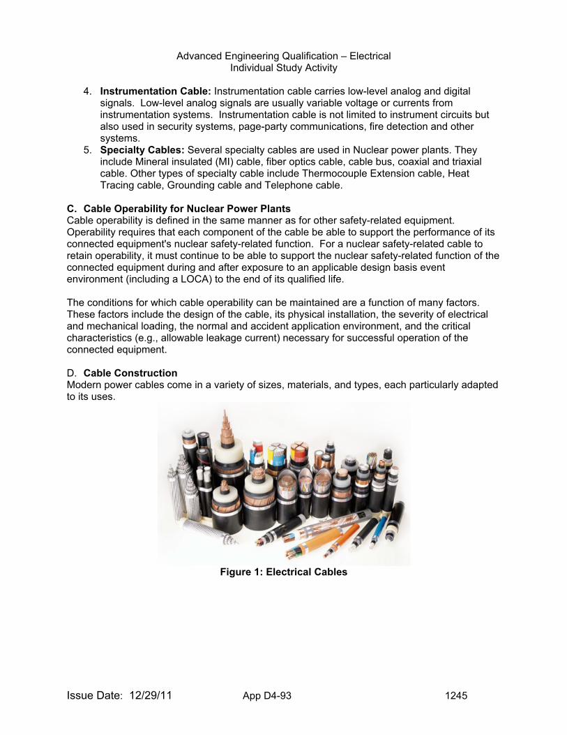
Advanced Engineering Qualification – Electrical Individual Study Activity
Issue Date: 12/29/11 App D4-93 1245
4. Instrumentation Cable: Instrumentation cable carries low-level analog and digital
signals. Low-level analog signals are usually variable voltage or currents from instrumentation systems. Instrumentation cable is not limited to instrument circuits but also used in security systems, page-party communications, fire detection and other systems.
5. Specialty Cables: Several specialty cables are used in Nuclear power plants. They include Mineral insulated (MI) cable, fiber optics cable, cable bus, coaxial and triaxial cable. Other types of specialty cable include Thermocouple Extension cable, Heat Tracing cable, Grounding cable and Telephone cable.
C. Cable Operability for Nuclear Power Plants Cable operability is defined in the same manner as for other safety-related equipment. Operability requires that each component of the cable be able to support the performance of its connected equipment's nuclear safety-related function. For a nuclear safety-related cable to retain operability, it must continue to be able to support the nuclear safety-related function of the connected equipment during and after exposure to an applicable design basis event environment (including a LOCA) to the end of its qualified life. The conditions for which cable operability can be maintained are a function of many factors. These factors include the design of the cable, its physical installation, the severity of electrical and mechanical loading, the normal and accident application environment, and the critical characteristics (e.g., allowable leakage current) necessary for successful operation of the connected equipment. D. Cable Construction Modern power cables come in a variety of sizes, materials, and types, each particularly adapted to its uses.
Figure 1: Electrical Cables
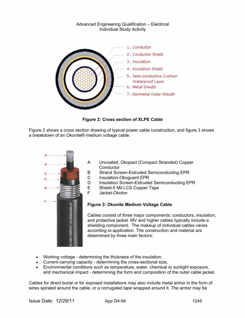
Advanced Engineering Qualification – Electrical Individual Study Activity
Issue Date: 12/29/11 App D4-94 1245
Figure 2: Cross section of XLPE Cable
Figure 2 shows a cross section drawing of typical power cable construction, and figure 3 shows a breakdown of an Okonite® medium voltage cable.
Figure 3: Okonite Medium Voltage Cable
Cables consist of three major components: conductors, insulation, and protective jacket. MV and higher cables typically include a shielding component. The makeup of individual cables varies according to application. The construction and material are determined by three main factors:
• Working voltage - determining the thickness of the insulation; • Current-carrying capacity - determining the cross-sectional size; • Environmental conditions such as temperature, water, chemical or sunlight exposure,
and mechanical impact - determining the form and composition of the outer cable jacket.
Cables for direct burial or for exposed installations may also include metal armor in the form of wires spiraled around the cable, or a corrugated tape wrapped around it. The armor may be
A Uncoated, Okopact (Compact Stranded) Copper Conductor
B Strand Screen-Extruded Semiconducting EPR C Insulation-Okoguard EPR D Insulation Screen-Extruded Semiconducting EPR E Shield-5 Mil LCS Copper Tape F Jacket-Okolon
Advanced Engineering Qualification – Electrical Individual Study Activity
Issue Date: 12/29/11 App D4-95 1245
made of steel or aluminum, and although connected to earth ground, it is not intended to carry current during normal operation.
Power cables use stranded copper or aluminum conductors. The cable may include uninsulated conductors used for the circuit neutral or for ground (earth) connection. For circuits operating at or above 2,000 volts between conductors, a conductive shield may surround each insulated conductor. The overall assembly may be round or flat. Non-conducting filler strands may be added to the assembly to maintain its shape. Special purpose power cables for overhead or vertical use may have additional elements such as steel or Kevlar structural supports. Some power cables for outdoor overhead use may have no overall sheath. Other cables may have a plastic or metal sheath enclosing all the conductors. The materials for the sheath will be selected for resistance to water, oil, sunlight, underground conditions, chemical vapors, impact, or high temperatures. In nuclear industry applications the cable may have special requirements for ionizing radiation resistance. Cable materials may be specified not to produce large amounts of smoke if burned. Cables intended for underground use or direct burial in earth will have heavy plastic or metal, most often lead sheaths, or may require special direct-buried construction. When cables must run where exposed to mechanical impact damage, they may be protected with flexible steel tape or wire armor, which may also be covered by a water resistant jacket. Electrical power cables are often installed in raceways, including electrical conduit and cable trays, which may contain one or more conductors.
Most multi-conductor cables today have a bare or insulated grounding or bonding wire which is for connection to earth ground. The grounding conductor connects equipment enclosures to ground for protection from electric shock.
There are several specialty cables with unique designs used in nuclear power plants. They include Mineral insulated (MI) cable, fiber optics cable, cablebus, coaxial and triaxial cable. MI cable construction, for instance, consist of a bare solid-copper conductor surrounded by magnesium oxide, silicone oxide, or aluminum oxide insulation covered by a copper or stainless steel tube. Given the uniqueness of the design in construction and fabrication, the conductor cannot be twisted inside. The insulation are very hygroscopic (absorb water/moisture easily) and lose dielectric strength with any insulation moisture intrusion. Special care must then be taken to seal the ends. This is done before and after installation by using potting compound, gland fitting or heat shrinks tubing. Mineral insulated cable can provide a 3-hour rated fire barrier. Cablebus is a pre-engineered, pre-design cable and raceway system for high-load current requirement (for example, generator leads or secondary leads on auxiliary transformers). The raceway system has rigorous support and bracing requirement because of high fault condition. Coaxial and triaxial cables are generally specified by manufacturer for application for low-level and /or high frequency signals.
E. Cable Sizing Cable sizing is dependent of several factors that may affect the ampacity, such as loading and environmental conditions. In nuclear power plants, cables are sized to carry the required normal, emergency overload, and short-circuit current without exceeding rated temperature of the insulation at the maximum expected ambient temperature. Sizing must also consider voltage regulation requirements, shield circulating current and mechanical strength. Cable ampacity must also consider the appropriate de-rating based on the ambient and installation conditions. Examples of parameters which must be considered when de-rating ampacity include conduit or tray fill, tray enclosure type, conductor temperature, ambient temperature and fire wrapping.
Advanced Engineering Qualification – Electrical Individual Study Activity
Issue Date: 12/29/11 App D4-96 1245
Ampacity tables (see IEEE Std 835) cover the installation conditions most commonly encountered. The tables relate to insulated cables in underground ducts, in free air, in conduit, and directly buried in earth. The values are based on 90°C and 105°C conductor temperatures and an ambient temperature of 20°C for all cables in underground duct or directly buried in the ground and 40°C for all cables in air. Ampacity values are based on a 100% load factor. By definition, the load factor is the ratio of the average load over a designated period of time to the peak load occurring in that period. For variable continuous loading the base period is 24 hours. These apply for cables in conventional underground duct installations as there is a time lag between the temperature rise of the cable and the temperature rise of the duct structure and surrounding earth. This heat-time-lag characteristic permits assigning higher current ratings for cables in ducts which do not carry full load continuously. For in-air installations 100% load factor is used.
Operation at the emergency overload temperature of 130°C or 140°C shall not exceed 100 hours in any twelve consecutive months nor more than 500 hours during the lifetime of the cable. Lower temperatures for emergency overload conditions may be required because of the type of material used in the cable, joints and terminations or because of cable environmental conditions. F. Voltage Drop Voltage regulation is often the limiting factor in the choice of either conductor or type of insulation. While the heat loss in the cable determines the maximum current it can safely carry without excessive deterioration, many circuits will be limited to currents lower than this in order to keep the voltage drop within permissible values. G. Cable Termination and Splicing Cable termination is the electrical and physical connection of the cable end to a piece of equipment such as terminal block, equipment pigtails, or bus bars of a device of equipment. There are a variety of termination methods for cable. The termination method used depends on the system installed, type of cable used and type of connector. Soldered connections, wire-wrapping connections, crimp connections, compression terminations, and loop or "eye" connections are the most common types of terminations used. Using the proper termination method allows for good mechanical and electrical integrity. No matter what type of termination, the most important thing is to use the proper tools and materials. A splice is the electrical connection of a cable end to another cable with the same cable number. Cable splices are designed and installed to interconnect two cable ends both electrically and physically. The physical requirements relate to mechanical security and environmental protection of the connection; the electrical requirements relate to current carrying capacity, connection voltage drop and compatibility of materials (e.g., thermocouple extension wire connections must join like conductor materials.
Advanced Engineering Qualification – Electrical Individual Study Activity
Issue Date: 12/29/11 App D4-97 1245
Crimp connections are connections using terminals having tubular openings into which the cable conductors are placed. The tube is then mechanically pressed or deformed to tighten it onto the conductor and form a connection. Crimping is performed typically by a crimping tool specially designed for the termination. For nuclear safety-related circuits, the crimping tools are calibrated and are generally used under quality control supervision to ensure proper connections. Crimp connections are commonly available in butt splice, ring lug, and spade lug formats. Crimp connections are available in a wide variety of sizes and may be found in instrument, control, and power circuits. Compression terminations are terminations in which the un-insulated conductor is inserted into a "box" and the connection is then made with a screw, a flat strap, or other such mechanism that compresses the conductor and forms the connection. Low-voltage circuit breakers use this type of connection. Examples of Event Reports to Review for Electric Cables 5292009001
04/22/2009 Palo Verde 2 Emergency Diesel Generator Fuel Oil Transfer Pump Failure
5291992004
06/19/1992 Palo Verde 2, Palo Verde 3 Unit 2 and Unit 3 Loss of Power (LOP) ESFAS
4981988008
01/20/1988 South Texas 1, South Texas 2 Safety - Related Electrical Cable Splices
2191990005
04/21/1990 Oyster Creek Technical Specification Required Shutdown Because of Loss Of Power to Safety Related Switchgear Due to Grounded Supply Cable
2602003004
07/07/2003 Browns Ferry 2, Browns Ferry 3 Cable Separations Design Error Related to Appendix R Requirements
Examples of Findings for Cables Initiating Event - Electrical Ground on Improperly Abandoned Cable Resulted in Reactor Trip A self-revealing finding was identified for an improperly abandoned cable in the non-safety related 250-VDC Battery Board 2 system that resulted in a reactor trip of Unit 1. A Design Change Notice (DCN) in 1999 required the cable to be disconnected and insulated on both ends; however, the work was done only on one end. The cable subsequently grounded and, in conjunction with a second ground, actuated a protective relay on the main bank transformer and tripped the unit. Mitigating Systems - Failure to Promptly Identify and Correct Deficient (unqualified) Okonite Cable Splices The inspectors identified a violation of 10 CFR 50, Appendix B, Criterion XVI, "Corrective Action," for failure to promptly identify and correct seven deficient Okonite cable splices at Unit 1 that were required to be environmentally qualified (EQ). The cable splices were repaired and EQ program deficiencies were addressed by the corrective action program. Multiple Examples of Cable Splices Inside Unit 1 Drywell That Were Not Environmentally Qualified The inspectors identified a non-cited violation (NCV) for multiple types of cable splices at Unit 1 that were not environmentally qualified. 10CFR 50.49(f) requires that each item of electric equipment important to safety within the scope of 10 CFR 50.49(b) must be qualified by one of several methods described in that section. As of April 2005, there were 11 Okonite cable splices, 47 Raychem splices and one barrel-type butt splice in the Unit 1 drywell that were not
Advanced Engineering Qualification – Electrical Individual Study Activity
Issue Date: 12/29/11 App D4-98 1245
environmentally qualified because these splices did not conform to the qualified configurations described in Procedure N1-EMP-GEN–003, "Insulating Medium and Low Voltage Power Connections Control and Instrumentation Cables." These cable splices were used in the control circuitry of motor-operated valves and solenoid-operated valves that were required for accident mitigation and the circuitry of temperature instruments that were required for accident monitoring. This electric equipment is within the scope of 10 CFR 50.49(b). Failure to Take Effective Corrective Actions Regarding Safety-Related l Cable Separation The inspectors identified a non-cited violation of 10 CFR 50, Appendix B, Criterion XVI, "Corrective Action," for the failure to take effective corrective actions to address cable separation deficiencies in the cable vault. This finding is considered to be greater than minor because it affected the Mitigating Systems cornerstone objective of equipment availability. Specifically, cable separation deficiencies continue to be identified by NRC inspectors in the safety related cable vault despite corrective actions taken by the licensee to address previous NRC-identified cable vault cable separation issues. The finding was determined to be of very low safety significance because no actual loss of safety function was identified. Examples of Information to Request for Inspection of Electrical Cables
• Construction and Bill of Material information for cables of concern • Procedures governing procurement, connection, maintenance and care of cables • Cable schedule drawings showing cable locations and routing • Procedures for inspection of medium voltage cables in manholes susceptible to water
intrusion • Cable sizing calculations
Training associated with Electrical Cables Medium Voltage Cables in Nuclear and Fossil Power Plants: Characteristics, Performance, Condition Assessment Understanding Power Cable Characteristics and Applications
EVALUATION CRITERIA: Upon completion of the tasks in this guide, you will be asked to demonstrate your
understanding of electrical cables as applicable to nuclear power plants by performing the following:
1. Discuss the items to be addressed when sizing cables for an application. What role
does ambient temperature play in sizing of cables? 2. Discuss construction of cable types. Include strengths and weakness of different
materials used as the conductor, insulation, and jacket. What is the purpose of a shield in a cable?
3. Discuss the requirements for derating of cables. Give examples of situations in which a safety related cable may be required to be de-rated.
4. Discuss cable performance with respect to: a. Thermal Stability b. Moisture Resistance c. Flame Propagation Resistance d. Radiation Resistance
5. Discuss voltage levels for cables and explain any differences between cables used in medium voltage applications to those used in low voltage applications.
6. Explain how cable sizes are classified. 7. Discuss the methods used to protect cables from the effects of fire.
Advanced Engineering Qualification – Electrical Individual Study Activity
Issue Date: 12/29/11 App D4-99 1245
8. Discuss aging effects on cables.
TASKS:
1. Read the references in sufficient detail to perform adequately in accordance with the requirements of the evaluation criteria.
2. Meet with your supervisor, or the person designated to be your resource for this activity, and discuss the answers to the questions listed under the evaluation criteria.
3. Familiarize yourself with the inspection resources listed under the Operational Experience website.
DOCUMENTATION: Advanced Engineering Qualification - Electrical
Signature Card Item ISA-EE-12
Advanced Engineering Qualification – Electrical Individual Study Activity
Issue Date: 12/29/11 App D4-100 1245
TOPIC: (ISA-EE-13) Equipment Protection PURPOSE: The purpose of this activity is to acquaint the inspector with the basic
concepts, operation and principles associated with equipment protection, including grounding, lightning protection, protective relaying, and associated equipment found in electrical distribution systems that provide or enhance equipment protection. It should be understood that the field of equipment protection is broad, and numerous methods exist.
COMPETENCY AREA: INSPECTION LEVEL OF EFFORT: As determined by Branch Chief or supervisor REFERENCES: All of the following documents can be obtained or accessed from the
NRC’s internal Website. 1. IEEE Std. 142 Grounding of Industrial and Commercial Power Systems 2. IEEE Std. 665 Guide for Generating Station Grounding 3. IEEE Std. C62.92 Guide for the Application of Neutral Grounding in Electric Utility
Systems 4. IEEE Std. 81 Guide for Measuring Earth Resistivity, Ground Impedance, and
Earth Surface Potentials of a Ground System 5. NUREG/CR-6866 Technical Basis for Regulatory Guidance on Lightning Protection
in Nuclear Power Plants 6. NFPA-780 Standard for the Installation of Lightning Protection Systems 7. IEEE Std. 62.23 Application Guide for Surge Protection of Electric Generating
Plants 8. IEEE Std. C57.13 Standard Requirements for Instrument Transformers 9. IEEE Std. 242 IEEE Recommended Practice for Protection and Coordination of
Industrial and Commercial Power Systems 10. IEEE Std. 741 IEEE Standard Criteria for the Protection of Class 1E Power
Systems and Equipment in Nuclear Power and Generating Stations
11. IEEE Std. C37.2 Standard for Electrical Power System Device Function Number, Acronyms, and Contact Designations
12. NEMA ICS-19 Diagrams Device Designations, and Symbols for Industrial Control and Systems
The following references are provided as general reference, and will aid in the understanding of the subject material: 1. NFPA – 70 National Electrical Code 2. IEEE Std. 80 Guide for Safety in AC Substation Grounding 3. IEEE Std. 666 Design Guide for Electrical Power Service Systems for
Generating Stations 4. Information Notice 85-86 Lightning Strikes at Nuclear Power Generating Stations 5. IEEE Std. 998 Guide for Direct Lightning Stroke Shielding of Substations
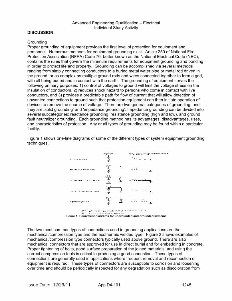
Advanced Engineering Qualification – Electrical Individual Study Activity
Issue Date: 12/29/11 App D4-101 1245
DISCUSSION: Grounding Proper grounding of equipment provides the first level of protection for equipment and personnel. Numerous methods for equipment grounding exist. Article 250 of National Fire Protection Association (NFPA) Code 70, better known as the National Electrical Code (NEC), contains the rules that govern the minimum requirements for equipment grounding and bonding in order to protect life and property. Grounding can be accomplished via several methods ranging from simply connecting conductors to a buried metal water pipe or metal rod driven in the ground, or as complex as multiple ground rods and wires connected together to form a grid, with all being buried and in contact with the earth. The grounding of equipment serves the following primary purposes: 1) control of voltages to ground will limit the voltage stress on the insulation of conductors, 2) reduces shock hazard to persons who come in contact with live conductors, and 3) provides a predictable path for flow of current that will allow detection of unwanted connections to ground such that protection equipment can then initiate operation of devices to remove the source of voltage. There are two general categories of grounding, and they are ‘solid grounding’ and ‘impedance grounding’. Impedance grounding can be divided into several subcategories: reactance grounding, resistance grounding (high and low), and ground fault neutralizer grounding. Each grounding method has its advantages, disadvantages, uses, and characteristics of protection. Any or all types of grounding may be found within a particular facility. Figure 1 shows one-line diagrams of some of the different types of system equipment grounding techniques.
The two most common types of connections used in grounding applications are the mechanical/compression type and the exothermic welded type. Figure 2 shows examples of mechanical/compression type connectors typically used above ground. There are also mechanical connectors that are approved for use in direct burial and for embedding in concrete. Proper tightening of bolts, good surface preparation of the joined materials, and using the correct compression tools is critical to producing a good connection. These types of connections are generally used in applications where frequent removal and reconnection of equipment is required. These types of connectors are susceptible to corrosion and loosening over time and should be periodically inspected for any degradation such as discoloration from
Figure 1: Equivalent diagrams for ungrounded and grounded systems

Advanced Engineering Qualification – Electrical Individual Study Activity
Issue Date: 12/29/11 App D4-102 1245
Figure 3: Examples of Cadwelded connections
overheating or galvanic action. In addition, these types of connections should be inspected for tightness after being exposed to any fault current conditions.
Exothermic welding, also known as Thermite welding (marketed under several trade names such as Thermoweld, Cadweld, or Burndyweld) is a permanent bonding process for joining two electrical conductors. The materials can be copper-to-copper or copper-to-steel. The process employs an exothermic reaction of a copper thermite composition to heat the copper, and requires no external source of heat or current. A semi-permanent graphite crucible mould is used, in which the molten copper flows through the mould and over and around the conductors to be welded, forming an electrically conductive weld between them. When the copper cools, the mould is either broken off or left in place. The weld formed has higher mechanical strength than other forms of weld, and excellent corrosion resistance. It is also highly stable when subject to repeated short-circuit pulses, and does not suffer from increased electrical resistance over the lifetime of the installation. The welding process can be impeded by wet conditions and should not be performed under these conditions without taking precautions to keep the joint dry. Exothermic welded connections are also typically found in buried or embedded installations, and on permanent above-ground installations, such as substation metal work. Improper installations of these types of connections include incorrect welding techniques, cold joints, poorly maintained or incorrect molds, improper surface preparation. Non-destructive examination techniques, such as radiographic testing, can be used to inspect the integrity of these connections. Figure 3 shows examples of cadwelded connections joining cable-to-cable and cables to ground rods. The ground rods are normally copper clad steel rods. Because no dissimilar metal connections are created in the welding process, this type of connection is also found in cathodic protection system splices and bonding. Lightning Protection - Lightning is a natural phenomenon and cannot be prevented. It can, however, be intercepted or diverted in such a way that equipment damage and personnel
Figure 2: Mechanical and compression type connector examples
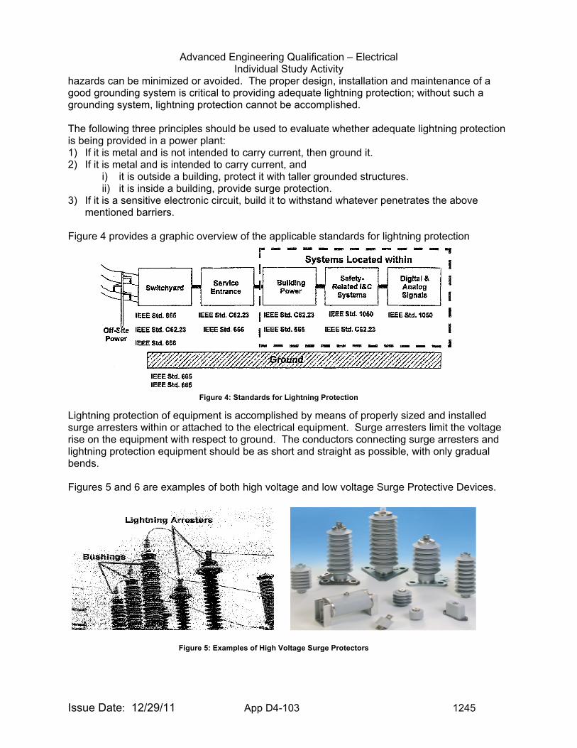
Advanced Engineering Qualification – Electrical Individual Study Activity
Issue Date: 12/29/11 App D4-103 1245
hazards can be minimized or avoided. The proper design, installation and maintenance of a good grounding system is critical to providing adequate lightning protection; without such a grounding system, lightning protection cannot be accomplished. The following three principles should be used to evaluate whether adequate lightning protection is being provided in a power plant: 1) If it is metal and is not intended to carry current, then ground it. 2) If it is metal and is intended to carry current, and
i) it is outside a building, protect it with taller grounded structures. ii) it is inside a building, provide surge protection.
3) If it is a sensitive electronic circuit, build it to withstand whatever penetrates the above mentioned barriers.
Figure 4 provides a graphic overview of the applicable standards for lightning protection
Lightning protection of equipment is accomplished by means of properly sized and installed surge arresters within or attached to the electrical equipment. Surge arresters limit the voltage rise on the equipment with respect to ground. The conductors connecting surge arresters and lightning protection equipment should be as short and straight as possible, with only gradual bends. Figures 5 and 6 are examples of both high voltage and low voltage Surge Protective Devices.
Figure 4: Standards for Lightning Protection
Figure 5: Examples of High Voltage Surge Protectors
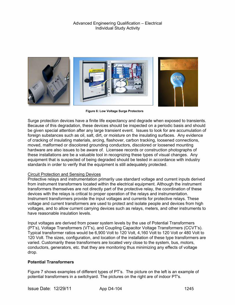
Advanced Engineering Qualification – Electrical Individual Study Activity
Issue Date: 12/29/11 App D4-104 1245
Surge protection devices have a finite life expectancy and degrade when exposed to transients. Because of this degradation, these devices should be inspected on a periodic basis and should be given special attention after any large transient event. Issues to look for are accumulation of foreign substances such as oil, salt, dirt, or moisture on the insulating surfaces. Any evidence of cracking of insulating materials, arcing, flashover, carbon tracking, loosened connections, moved, malformed or discolored grounding conductors, discolored or loosened mounting hardware are also issues to be aware of. Licensee records or construction photographs of these installations are be a valuable tool in recognizing these types of visual changes. Any equipment that is suspected of being degraded should be tested in accordance with industry standards in order to verify that the equipment is still adequately protected. Circuit Protection and Sensing Devices Protective relays and instrumentation primarily use standard voltage and current inputs derived from instrument transformers located within the electrical equipment. Although the instrument transformers themselves are not directly part of the protective relay, the coordination of these devices with the relays is critical to proper operation of the relays and instrumentation. Instrument transformers provide the input voltages and currents for protective relays. These voltage and current transformers are used to protect and isolate people and devices from high voltages, and to allow current carrying devices such as relays, meters, and other instruments to have reasonable insulation levels. Input voltages are derived from power system levels by the use of Potential Transformers (PT’s), Voltage Transformers (VT’s), and Coupling Capacitor Voltage Transformers (CCVT’s). Typical transformer ratios would be 6,900 Volt to 120 Volt, 4,160 Volt to 120 Volt or 480 Volt to 120 Volt. The sizes, configuration, and location of the installation of these type transformers are varied. Customarily these transformers are located very close to the system, bus, motors, conductors, generators, etc. that they are monitoring thus minimizing any effects of voltage drop. Potential Transformers Figure 7 shows examples of different types of PT’s. The picture on the left is an example of potential transformers in a switchyard. The pictures on the right are of indoor PT's.
Figure 6: Low Voltage Surge Protectors
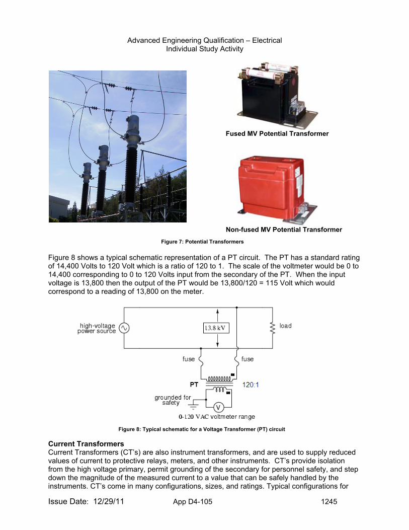
Advanced Engineering Qualification – Electrical Individual Study Activity
Issue Date: 12/29/11 App D4-105 1245
Fused MV Potential Transformer
Non-fused MV Potential Transformer
Figure 8 shows a typical schematic representation of a PT circuit. The PT has a standard rating of 14,400 Volts to 120 Volt which is a ratio of 120 to 1. The scale of the voltmeter would be 0 to 14,400 corresponding to 0 to 120 Volts input from the secondary of the PT. When the input voltage is 13,800 then the output of the PT would be 13,800/120 = 115 Volt which would correspond to a reading of 13,800 on the meter.
Current Transformers Current Transformers (CT’s) are also instrument transformers, and are used to supply reduced values of current to protective relays, meters, and other instruments. CT’s provide isolation from the high voltage primary, permit grounding of the secondary for personnel safety, and step down the magnitude of the measured current to a value that can be safely handled by the instruments. CT’s come in many configurations, sizes, and ratings. Typical configurations for
Figure 7: Potential Transformers
Figure 8: Typical schematic for a Voltage Transformer (PT) circuit
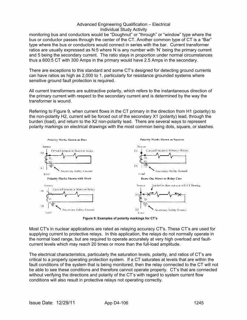
Advanced Engineering Qualification – Electrical Individual Study Activity
Issue Date: 12/29/11 App D4-106 1245
monitoring bus and conductors would be “Doughnut” or “through” or “window” type where the bus or conductor passes through the center of the CT. Another common type of CT is a “Bar” type where the bus or conductors would connect in series with the bar. Current transformer ratios are usually expressed as N:5 where N is any number with ‘N’ being the primary current and 5 being the secondary current. The ratio stays in proportion under normal circumstances thus a 600:5 CT with 300 Amps in the primary would have 2.5 Amps in the secondary. There are exceptions to this standard and some CT’s designed for detecting ground currents can have ratios as high as 2,000 to 1, particularly for resistance grounded systems where sensitive ground fault protection is required. All current transformers are subtractive polarity, which refers to the instantaneous direction of the primary current with respect to the secondary current and is determined by the way the transformer is wound. Referring to Figure 9, when current flows in the CT primary in the direction from H1 (polarity) to the non-polarity H2, current will be forced out of the secondary X1 (polarity) lead, through the burden (load), and return to the X2 non-polarity lead. There are several ways to represent polarity markings on electrical drawings with the most common being dots, square, or slashes.
Most CT's in nuclear applications are rated as relaying accuracy CT's. These CT’s are used for supplying current to protective relays. In this application, the relays do not normally operate in the normal load range, but are required to operate accurately at very high overload and fault-current levels which may reach 20 times or more than the full-load amplitude. The electrical characteristics, particularly the saturation levels, polarity, and ratios of CT’s are critical to a properly operating protection system. If a CT saturates at levels that are within the fault conditions of the system that is being monitored, then the relay connected to the CT will not be able to see these conditions and therefore cannot operate properly. CT’s that are connected without verifying the directions and polarity of the CT’s with regard to system current flow conditions will also result in protective relays not operating correctly.
Figure 9: Examples of polarity markings for CT’s
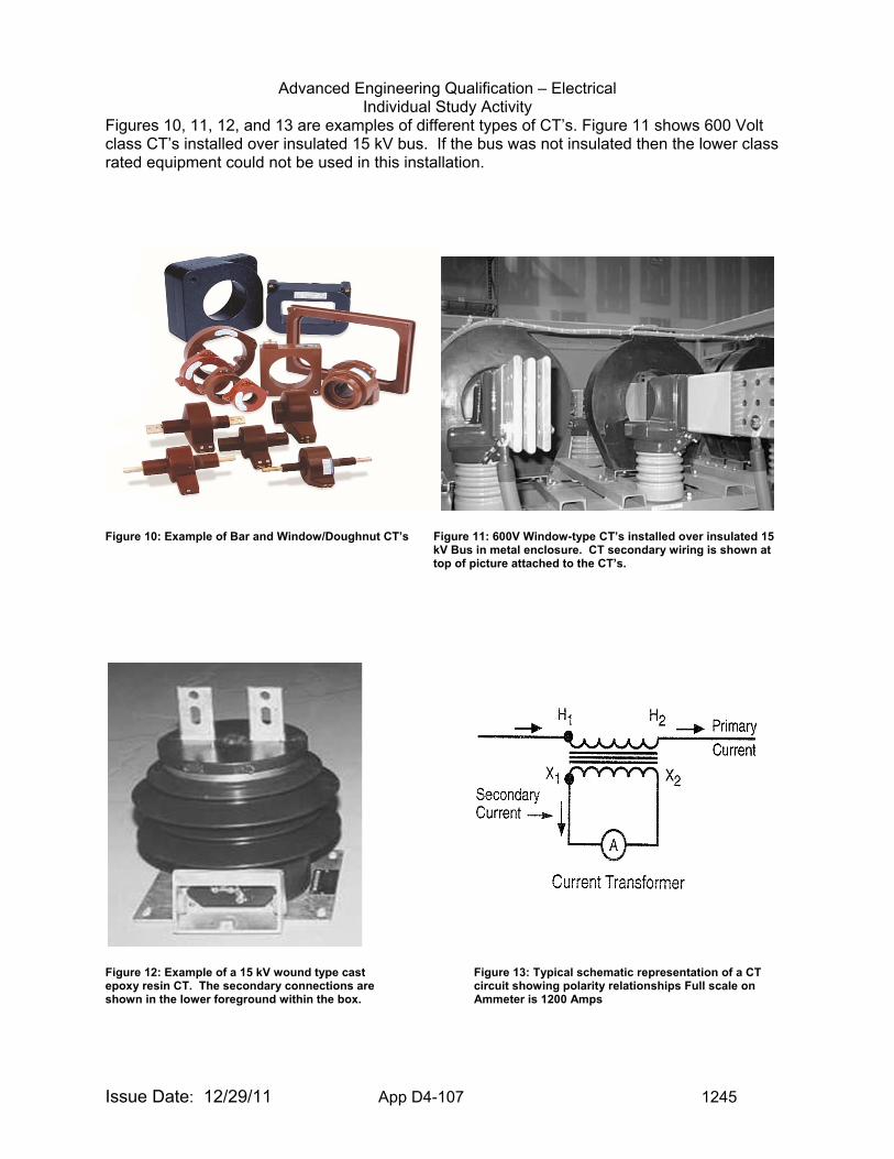
Advanced Engineering Qualification – Electrical Individual Study Activity
Issue Date: 12/29/11 App D4-107 1245
Figures 10, 11, 12, and 13 are examples of different types of CT’s. Figure 11 shows 600 Volt class CT’s installed over insulated 15 kV bus. If the bus was not insulated then the lower class rated equipment could not be used in this installation.
Figure 10: Example of Bar and Window/Doughnut CT’s Figure 11: 600V Window-type CT’s installed over insulated 15
kV Bus in metal enclosure. CT secondary wiring is shown at top of picture attached to the CT’s.
Figure 12: Example of a 15 kV wound type cast Figure 13: Typical schematic representation of a CT epoxy resin CT. The secondary connections are circuit showing polarity relationships Full scale on shown in the lower foreground within the box. Ammeter is 1200 Amps
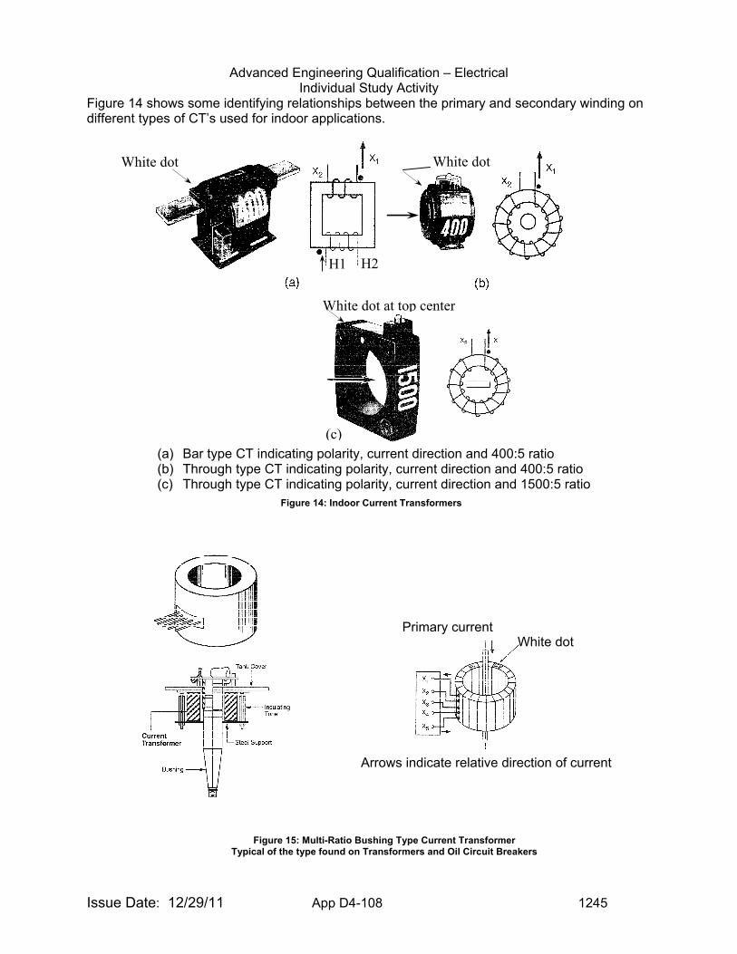
Advanced Engineering Qualification – Electrical Individual Study Activity
Issue Date: 12/29/11 App D4-108 1245
Figure 14 shows some identifying relationships between the primary and secondary winding on different types of CT’s used for indoor applications.
(a) Bar type CT indicating polarity, current direction and 400:5 ratio (b) Through type CT indicating polarity, current direction and 400:5 ratio (c) Through type CT indicating polarity, current direction and 1500:5 ratio
H2
White dot
White dot at top center
(c)
H1
White dot
White dot
Arrows indicate relative direction of current
Primary current
Figure 14: Indoor Current Transformers
Figure 15: Multi-Ratio Bushing Type Current Transformer Typical of the type found on Transformers and Oil Circuit Breakers
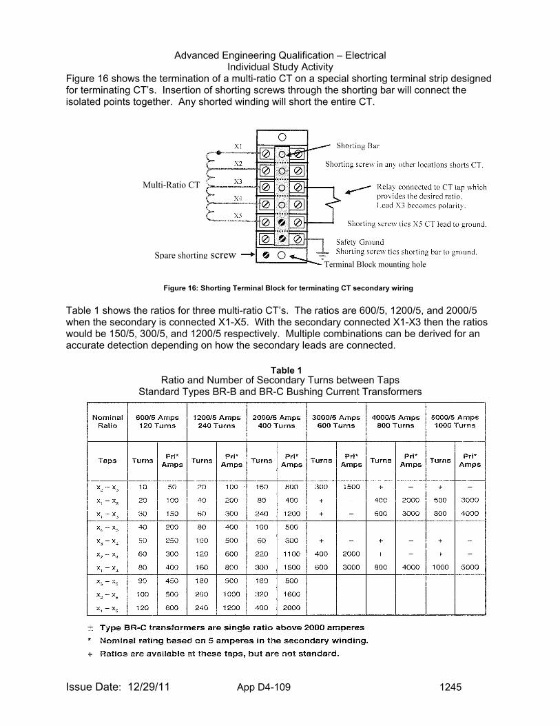
Advanced Engineering Qualification – Electrical Individual Study Activity
Issue Date: 12/29/11 App D4-109 1245
Figure 16 shows the termination of a multi-ratio CT on a special shorting terminal strip designed for terminating CT’s. Insertion of shorting screws through the shorting bar will connect the isolated points together. Any shorted winding will short the entire CT.
Table 1 shows the ratios for three multi-ratio CT’s. The ratios are 600/5, 1200/5, and 2000/5 when the secondary is connected X1-X5. With the secondary connected X1-X3 then the ratios would be 150/5, 300/5, and 1200/5 respectively. Multiple combinations can be derived for an accurate detection depending on how the secondary leads are connected.
Ratio and Number of Secondary Turns between Taps
Standard Types BR-B and BR-C Bushing Current Transformers
Spare shorting screw
Multi-Ratio CT
Terminal Block mounting hole
Figure 16: Shorting Terminal Block for terminating CT secondary wiring
Table 1
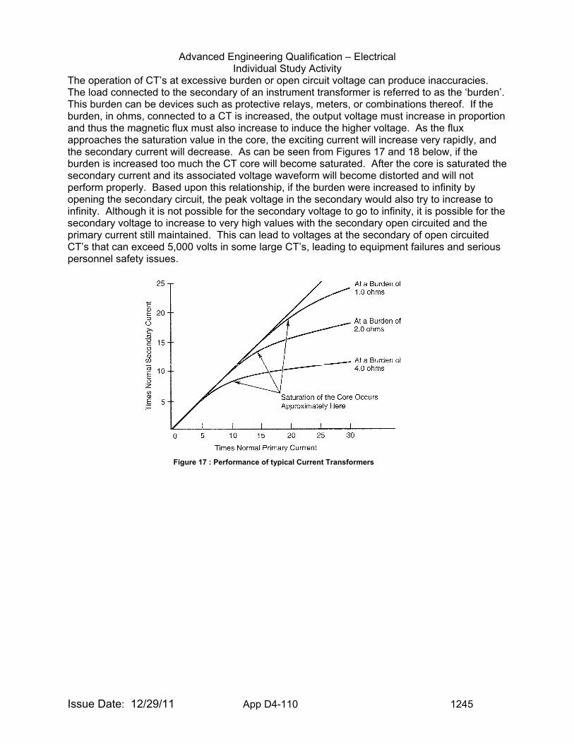
Advanced Engineering Qualification – Electrical Individual Study Activity
Issue Date: 12/29/11 App D4-110 1245
The operation of CT’s at excessive burden or open circuit voltage can produce inaccuracies. The load connected to the secondary of an instrument transformer is referred to as the ‘burden’. This burden can be devices such as protective relays, meters, or combinations thereof. If the burden, in ohms, connected to a CT is increased, the output voltage must increase in proportion and thus the magnetic flux must also increase to induce the higher voltage. As the flux approaches the saturation value in the core, the exciting current will increase very rapidly, and the secondary current will decrease. As can be seen from Figures 17 and 18 below, if the burden is increased too much the CT core will become saturated. After the core is saturated the secondary current and its associated voltage waveform will become distorted and will not perform properly. Based upon this relationship, if the burden were increased to infinity by opening the secondary circuit, the peak voltage in the secondary would also try to increase to infinity. Although it is not possible for the secondary voltage to go to infinity, it is possible for the secondary voltage to increase to very high values with the secondary open circuited and the primary current still maintained. This can lead to voltages at the secondary of open circuited CT’s that can exceed 5,000 volts in some large CT’s, leading to equipment failures and serious personnel safety issues.
Figure 17 : Performance of typical Current Transformers

Advanced Engineering Qualification – Electrical Individual Study Activity
Issue Date: 12/29/11 App D4-111 1245
Caution: The secondary of a CT must always be connected to a burden (load). An open-circuited secondary can result in the development of a dangerously high secondary voltage. Any energized but unused CT’s must have the secondary leads short-circuited and grounded.
Figure 18: Effect of excessive burden on a Current Transformer
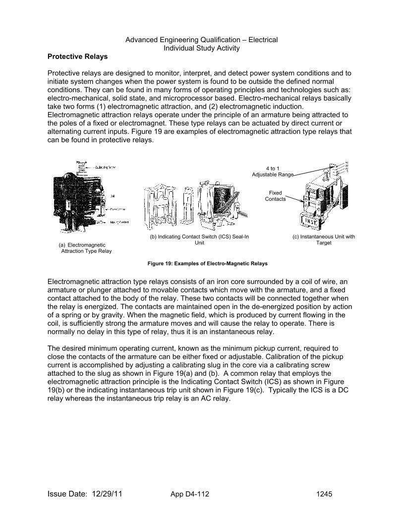
Advanced Engineering Qualification – Electrical Individual Study Activity
Issue Date: 12/29/11 App D4-112 1245
Protective Relays Protective relays are designed to monitor, interpret, and detect power system conditions and to initiate system changes when the power system is found to be outside the defined normal conditions. They can be found in many forms of operating principles and technologies such as: electro-mechanical, solid state, and microprocessor based. Electro-mechanical relays basically take two forms (1) electromagnetic attraction, and (2) electromagnetic induction. Electromagnetic attraction relays operate under the principle of an armature being attracted to the poles of a fixed or electromagnet. These type relays can be actuated by direct current or alternating current inputs. Figure 19 are examples of electromagnetic attraction type relays that can be found in protective relays.
Electromagnetic attraction type relays consists of an iron core surrounded by a coil of wire, an armature or plunger attached to movable contacts which move with the armature, and a fixed contact attached to the body of the relay. These two contacts will be connected together when the relay is energized. The contacts are maintained open in the de-energized position by action of a spring or by gravity. When the magnetic field, which is produced by current flowing in the coil, is sufficiently strong the armature moves and will cause the relay to operate. There is normally no delay in this type of relay, thus it is an instantaneous relay. The desired minimum operating current, known as the minimum pickup current, required to close the contacts of the armature can be either fixed or adjustable. Calibration of the pickup current is accomplished by adjusting a calibrating slug in the core via a calibrating screw attached to the slug as shown in Figure 19(a) and (b). A common relay that employs the electromagnetic attraction principle is the Indicating Contact Switch (ICS) as shown in Figure 19(b) or the indicating instantaneous trip unit shown in Figure 19(c). Typically the ICS is a DC relay whereas the instantaneous trip relay is an AC relay.
(a) Electromagnetic Attraction Type Relay
(b) Indicating Contact Switch (ICS) Seal-In Unit
(c) Instantaneous Unit with Target
4 to 1 Adjustable Range
Fixed Contacts
Figure 19: Examples of Electro-Magnetic Relays
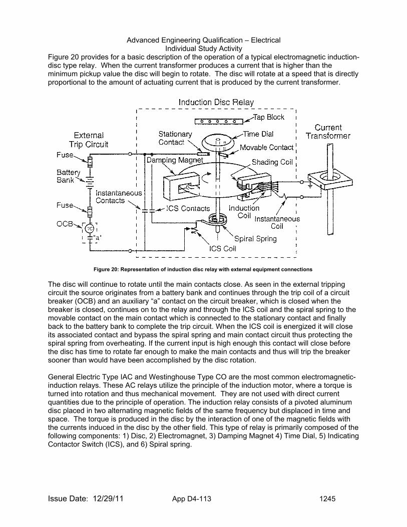
Advanced Engineering Qualification – Electrical Individual Study Activity
Issue Date: 12/29/11 App D4-113 1245
Figure 20 provides for a basic description of the operation of a typical electromagnetic induction-disc type relay. When the current transformer produces a current that is higher than the minimum pickup value the disc will begin to rotate. The disc will rotate at a speed that is directly proportional to the amount of actuating current that is produced by the current transformer.
The disc will continue to rotate until the main contacts close. As seen in the external tripping circuit the source originates from a battery bank and continues through the trip coil of a circuit breaker (OCB) and an auxiliary “a” contact on the circuit breaker, which is closed when the breaker is closed, continues on to the relay and through the ICS coil and the spiral spring to the movable contact on the main contact which is connected to the stationary contact and finally back to the battery bank to complete the trip circuit. When the ICS coil is energized it will close its associated contact and bypass the spiral spring and main contact circuit thus protecting the spiral spring from overheating. If the current input is high enough this contact will close before the disc has time to rotate far enough to make the main contacts and thus will trip the breaker sooner than would have been accomplished by the disc rotation. General Electric Type IAC and Westinghouse Type CO are the most common electromagnetic-induction relays. These AC relays utilize the principle of the induction motor, where a torque is turned into rotation and thus mechanical movement. They are not used with direct current quantities due to the principle of operation. The induction relay consists of a pivoted aluminum disc placed in two alternating magnetic fields of the same frequency but displaced in time and space. The torque is produced in the disc by the interaction of one of the magnetic fields with the currents induced in the disc by the other field. This type of relay is primarily composed of the following components: 1) Disc, 2) Electromagnet, 3) Damping Magnet 4) Time Dial, 5) Indicating Contactor Switch (ICS), and 6) Spiral spring.
Figure 20: Representation of induction disc relay with external equipment connections
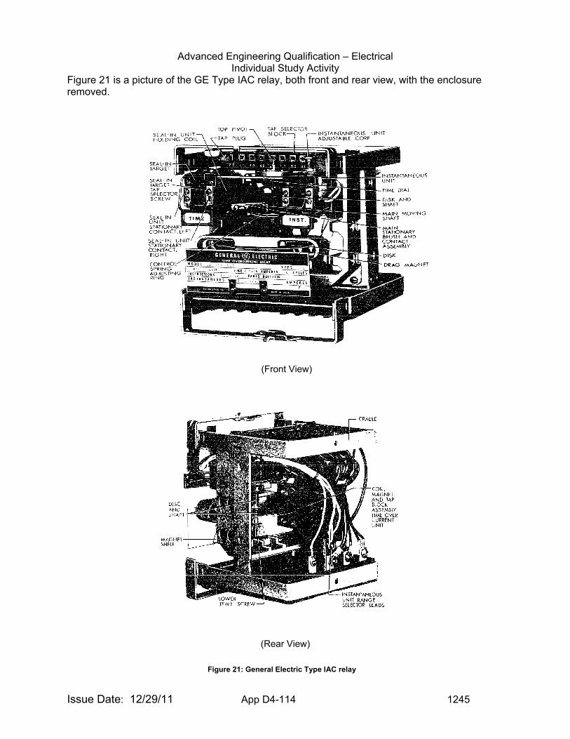
Advanced Engineering Qualification – Electrical Individual Study Activity
Issue Date: 12/29/11 App D4-114 1245
Figure 21 is a picture of the GE Type IAC relay, both front and rear view, with the enclosure removed.
Figure 31
(Front View)
(Rear View) Figure 21: General Electric Type IAC relay
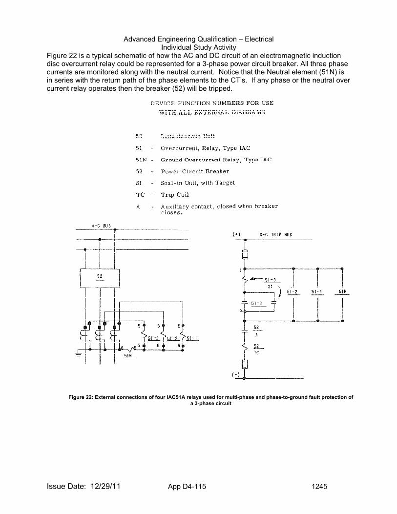
Advanced Engineering Qualification – Electrical Individual Study Activity
Issue Date: 12/29/11 App D4-115 1245
Figure 22 is a typical schematic of how the AC and DC circuit of an electromagnetic induction disc overcurrent relay could be represented for a 3-phase power circuit breaker. All three phase currents are monitored along with the neutral current. Notice that the Neutral element (51N) is in series with the return path of the phase elements to the CT’s. If any phase or the neutral over current relay operates then the breaker (52) will be tripped.
Figure 22: External connections of four IAC51A relays used for multi-phase and phase-to-ground fault protection of a 3-phase circuit
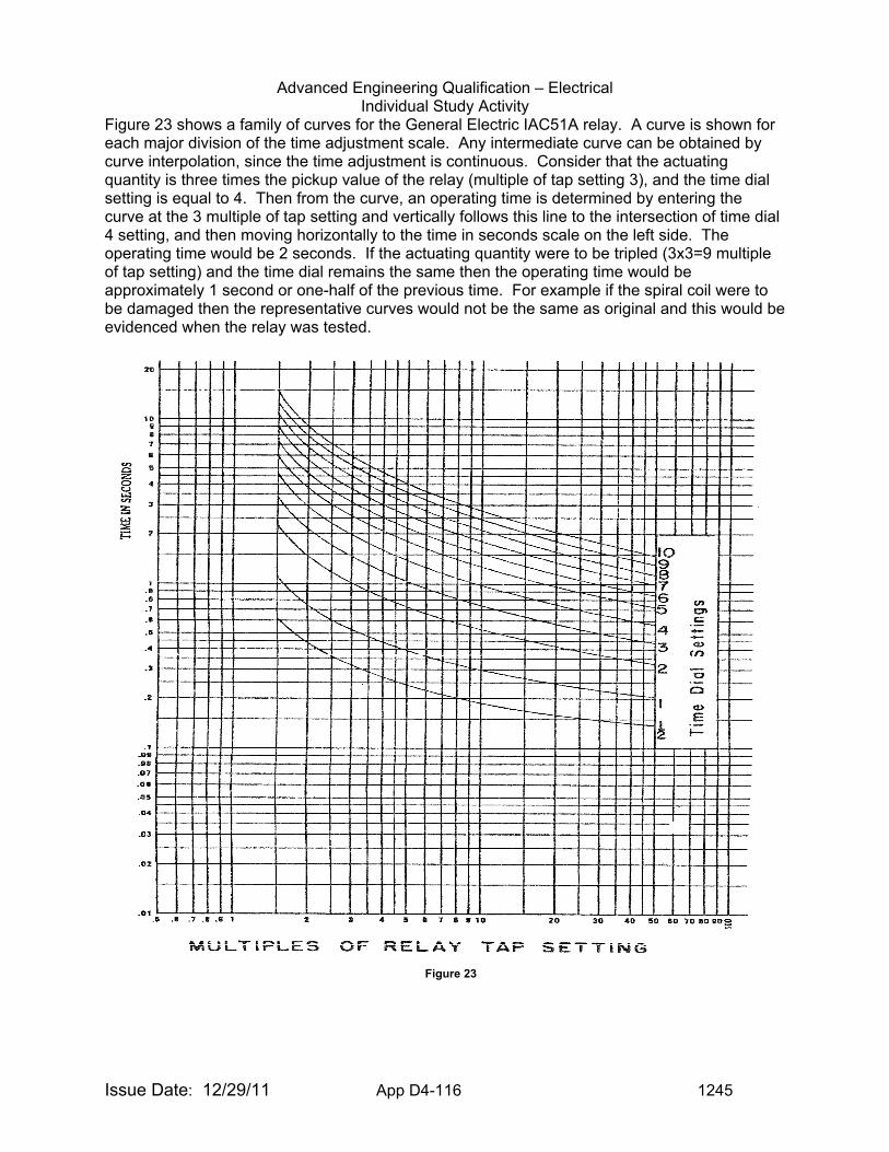
Advanced Engineering Qualification – Electrical Individual Study Activity
Issue Date: 12/29/11 App D4-116 1245
Figure 23 shows a family of curves for the General Electric IAC51A relay. A curve is shown for each major division of the time adjustment scale. Any intermediate curve can be obtained by curve interpolation, since the time adjustment is continuous. Consider that the actuating quantity is three times the pickup value of the relay (multiple of tap setting 3), and the time dial setting is equal to 4. Then from the curve, an operating time is determined by entering the curve at the 3 multiple of tap setting and vertically follows this line to the intersection of time dial 4 setting, and then moving horizontally to the time in seconds scale on the left side. The operating time would be 2 seconds. If the actuating quantity were to be tripled (3x3=9 multiple of tap setting) and the time dial remains the same then the operating time would be approximately 1 second or one-half of the previous time. For example if the spiral coil were to be damaged then the representative curves would not be the same as original and this would be evidenced when the relay was tested.
Figure 23
Advanced Engineering Qualification – Electrical Individual Study Activity
Issue Date: 12/29/11 App D4-117 1245
Typical problems associated with these types of relays are corroded, burned, or pitted contacts that will prevent proper operation of the connected circuits. Another problem is an overheated spiral coil that will be evidenced by a discolored coil. A disc that is not centered within the electro-magnets or that has accumulated dirt or dust can cause excessive drag on the disc. Any presence of moisture or other contaminants is an indication that the relays case is not sealed properly or that the relay is installed in a harmful environment. Any jeweled bearings that have dirt on them or that have been lubricated can also cause the relay to not operate correctly. Changing of components external to the relay such as CT’s, PT’s, trip coils, etc. without confirming burden and coordination with the relay can also render the relay inoperable or cause misoperation. These relays can have many different types and combinations of inputs such as Current, Voltage, and Frequency. Typical applications for these relays are to detect: overloads, overvoltage, under-voltage, over-frequency, under-frequency, open-phase, single-phase, phase-unbalance conditions, over-temperature, over-pressure, etc. and can be found installed in any type of electrical equipment. With the aging of these electromechanical relays and the inability to repair and service these older relays, electronic relays are gradually replacing the older relays. However many replacement electronic relays do not have the ability to directly connect to some of the older external devices such as high burden trip coils and contactors and thus interposing or auxiliary relays are required to interface these devices. These interfaces and equipment replacements are areas that should be looked at very carefully to determine if correct operation has been maintained Solid-state and microprocessor relays offer a significant number of advantages over their mechanical counterparts, including reliability, sophistication, reduced maintenance, documentation, and ease of adjustment. At the same time, however, they are sensitive to voltage spikes and require additional test precautions. Many manufactures make replacement solid-state relays for the older electro-mechanical relays. These newer relays have the capability of being programmed to duplicate the older relay(s) time-characteristic curves with curves that are menu selectable. The newer relays can have 100’s of pre-programmed selectable curves available or the user can create their own customized curves. A single solid-state relay can replace several of the older relay(s) functionality all in one unit. Figure 24 shows a Basler Feeder Protection solid-state relay that can replace the functionality of 4 General Electric IAC51 relays. This relay has many additional capabilities such as direct interface to a local or remote computer, on board data logging, trending, and capture of events before and after a trip. In addition the documentation of all programmed setpoints, limits, and parameters is easily obtained in a digital format such as a disc or electronic file for easy printing and viewing. No more need to try to decipher hand written notes on relay settings from relay test sheets.
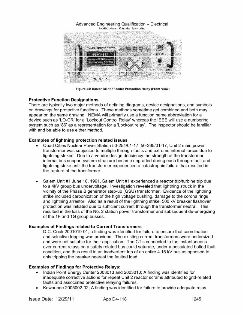
Advanced Engineering Qualification – Electrical Individual Study Activity
Issue Date: 12/29/11 App D4-118 1245
Protective Function Designations There are typically two major methods of defining diagrams, device designations, and symbols on drawings for protective functions. These methods sometime get combined and both may appear on the same drawing. NEMA will primarily use a function name abbreviation for a device such as ‘LO-CR’ for a ‘Lockout Control Relay’ whereas the IEEE will use a numbering system such as ‘86’ as a representation for a ‘Lockout relay’. The inspector should be familiar with and be able to use either method. Examples of lightning protection related issues
• Quad Cities Nuclear Power Station 50-254/01-17; 50-265/01-17, Unit 2 main power transformer was subjected to multiple through-faults and extreme internal forces due to lightning strikes. Due to a vendor design deficiency the strength of the transformer internal bus support system structure became degraded during each through-fault and lightning strike until the transformer experienced a catastrophic failure that resulted in the rupture of the transformer.
• Salem Unit #1 June 16, 1991, Salem Unit #1 experienced a reactor trip/turbine trip due to a 4kV group bus undervoltage. Investigation revealed that lightning struck in the vicinity of the Phase B generator step-up (GSU) transformer. Evidence of the lightning strike included carbonization of the high voltage bushing, damage to the corona rings and lightning arrestor. Also as a result of the lightning strike, 500 kV breaker flashover protection was initiated due to sufficient current through the transformer neutral. This resulted in the loss of the No. 2 station power transformer and subsequent de-energizing of the 1F and 1G group busses.
Examples of Findings related to Current Transformers D.C. Cook 2001019-01, a finding was identified for failure to ensure that coordination and selective tripping was provided. The existing current transformers were undersized and were not suitable for their application. The CT’s connected to the instantaneous over current relays on a safety related bus could saturate, under a postulated bolted fault condition, and thus result in an inadvertent trip of an entire 4.16 kV bus as opposed to only tripping the breaker nearest the faulted load.
Examples of Findings for Protective Relays:
• Indian Point Energy Center 2003013 and 2003010; A finding was identified for inadequate corrective actions for repeat Unit 2 reactor scrams attributed to grid-related faults and associated protective relaying failures.
• Kewaunee 2005002-02; A finding was identified for failure to provide adequate relay
Figure 24: Basler BE-11f Feeder Protection Relay (Front View)
Advanced Engineering Qualification – Electrical Individual Study Activity
Issue Date: 12/29/11 App D4-119 1245
setpoint calibration tolerances on the 4160 Vac safety bus 1-5 loss of voltage relays and overcurrent relays. Due to lack of coordination between the undervoltage relay settings and the overcurrent relay settings, under a postulated fault condition, the safety bus 1-5 could be disconnected from the normal source Tertiary Auxiliary Transformer (TAT) and not be locked out. After being disconnected from the TAT from an undervoltage condition the safety bus 1-5 would then be automatically connected to the alternate source, Reserve Auxiliary Transformer (RAT), without regard to the fault condition and subsequently would then have to be disconnected again from the alternate source due to the overcurrent conditions. This design deficiency and lack of coordination between the relays would result in a challenge to the safety related equipment reliability and availability.
Examples of Information to Request for Inspection of Equipment Protection Issues: For any inspection to be successful, the inspector must request the right information in order to evaluate whether the licensee is correctly interpreting and applying requirements, industry standards, lessons learned and industry best practices. The following examples may be useful in requesting licensee information.
• Documentation of the latest ground resistance testing • Drawings showing the grounding and lightning protection systems • Surveillance reports associated with the plant grounding and lightning protection
systems • List of Problem Reports associated with grounding or lightning protection systems in the
Corrective Action Program which should include any repairs to surge protection equipment
• Any site specific OE information concerning failures of insulators due to contamination • All 50.59 screenings and evaluations involving new equipment installations, PT’s, CT’s,
and protective relaying • Documentation of inspection of lightning protection systems • Maintenance and calibration procedures for protective relays • Receipt inspection documentation for protective relays • Maintenance Rule documentation involving protective relays • Specific calibration and testing results for protective relays • Any protection design studies and analysis performed • Characteristic and saturation curves for Current Transformers • List of Electrical Calculations • List of Electrical Design Basis documents • List of problem reports on protective relays in the Corrective Action Program • Elementary and one-line drawings of the Electrical Distribution System • Vendor Manuals • Manufacturers test report data and data sheets • Equipment specifications • Protective relay setpoint calculations and setting sheets
Items of Interest to Inspectors for Equipment Protection: Grounding, Lightning Protection, Surge Protection, and Protective relaying play a vital role in the safe operation of nuclear power plants. Problems may be found in several areas including programmatic, procedural, and maintenance. Each area should be reviewed for potential weaknesses involving the operation, testing, calibration, and maintenance of these systems.
Advanced Engineering Qualification – Electrical Individual Study Activity
Issue Date: 12/29/11 App D4-120 1245
Training and manuals associated with Protective Relays: Fundamentals of Modern Protective Relaying Interactive CD
www.gedigitalenergy.com/multilin/trainingcd/fmpr
Protective Device Coordination I & II www.electricaltrainingservices.com
Protective Relay Training www.abb.com
Electromechanical relay manuals www.gedigitalenergy.com,www.abb.com
EVALUATION CRITERIA: Upon completion of the tasks in this guide, you will be asked to
demonstrate your understanding of Equipment Protection by performing the following:
1. Become familiar with, and be able to identify the different types of grounding systems,
(IEEE Std. 142) 2. Discuss the differences between neutral ground, equipment ground, and safety ground.
(IEEE 665 Section 4.1) 3. List five grounding principles/requirements that should be met for a properly designed
safety and equipment grounding system. (IEEE 665) 4. Discuss the characteristics of each type of grounding system. (IEEE Std. C62.92 and
IEEE Std. 665) 5. Become familiar with the theory of the Fall of Potential methods for measuring earth
resistance (IEEE 81 Annex C) 6. Become familiar with the different types of instrumentation and equipment used to
measure grounding system resistance. (IEEE 81) 7. Discuss the difference between step potential and touch potential and the hazards
associated with each. (IEEE 81) 8. Discuss the seven key lightning protection issues associated with a nuclear power plant.
(NUREG/CR 6866) 9. Describe six things that should be included in any visual inspection of a Lightning
Protection system. (NFPA 780) 10. What is the recommended frequency a lightning protection system should be visually
inspected and what occurrences might prompt a more frequent inspection routine? (NFPA 780)
11. What is the transformer ratio for a PT connected to a 27-relay monitoring the 4,160 Volt Safety Bus? The 27 relay is used to initiate the start of an Emergency Diesel Generator. (IEEE Std. C57.13 and Discussion section)
12. Given the following CT data: 10 C 400 and 0.6 B 0.9 • Identify which CT would be connected to a revenue meter and which CT would
be connected to the protective relay. • What is the maximum ratio error of each CT? • What is the maximum burden of each CT? • What is the maximum VA rating of each CT? • What is the maximum secondary voltage developed at 20-times rated current of
the relaying CT? (IEEE Std. C57.13 and Discussion section) 13. Give the full scale reading of the Ammeter and secondary current value for the CT’s
monitoring the feeder conductors connecting a pump whose FLA is 1750 Amps if the CT
Advanced Engineering Qualification – Electrical Individual Study Activity
Issue Date: 12/29/11 App D4-121 1245
ratio’s is 2000:5 and the motor is running at 93 percent FLA. (IEEE Std. C57.13 and Discussion section)
14. Of the following relays, list the order of speed (from fastest to slowest) that each will provide protection: (IEEE Std. 242 and IEEE Std. 741) • Feeder Breaker over-current relay • Motor Bus over-current relay • Transformer differential relay.
15. List the name and function for the following IEEE Device Number devices: 16, 27, 38, 49, 50, 51, 52, 59, 63, 71, 81, 86, and 87. (IEEE Std. C37.2 and NEMA ICS-19)
16. List the name of the following abbreviations: HMI, SER, and RTU. (IEEE Std. C37.2 and NEMA ICS-19)
TASKS:
1. Become familiar with the references in sufficient detail to perform adequately in accordance with the requirements of the evaluation criteria.
2. Meet with your supervisor, or the person designated to be your resource for this activity, and discuss the answers to the questions listed under the evaluation criteria.
3. Familiarize yourself with the inspection resources listed under the Operational Experience website.
4. Familiarize yourself with the documentation necessary to perform inspections of Lightning Protection Equipment, Instrument Transformers and Protective Relaying.
DOCUMENTATION: Advanced Engineering Qualification – Electrical Signature Card Item ISA-
EE-13
Advanced Engineering Qualification – Electrical Individual Study Activity
Issue Date: 12/29/11 App D4-122 1245
TOPIC: (ISA-EE-14) Switchgear, Load/Distribution Centers, Motor Control Centers and Controllers
PURPOSE: The purpose of this guide is to provide the inspector with background
knowledge to inspect and to evaluate this electrical area. COMPETENCY AREA: INSPECTION LEVEL OF EFFORT: As determined by Branch Chief or supervisor REFERENCES: 1. IEEE Std C37.100 IEEE Standard Definitions for Power Switchgear 2. IEEE Std C37.2 IEEE Standard Electrical Power System Device Function
Numbers and Contact Designations 3. IEEE Std 902 IEEE Guide for Maintenance, Operation, and Safety of
Industrial and Commercial Power Systems 4. IEEE Std 323 IEEE Standard for Qualifying Class 1E Equipment for
Nuclear Power Generating Stations 5. IEEE Std 649 IEEE Standard for Qualifying Class 1E Motor Control
Centers for Nuclear Power generating Stations 6. ANSI C37.55 American National Standard for Switchgear, Medium
Voltage Metal-Clad Assemblies—Conformance Test Procedures
7. IEEE Std 344 Recommended Practice for Seismic Qualification of Class 1E Equipment for Nuclear Power Generating Stations
8. IN No. 88-11 Potential Loss of Motor Control Center and/or Switchboard Function due to Faulty Tie Bolts
9. IN No. 2002-01 Metalclad Switchgear Failures and Consequent Losses of Offsite Power
10. IN No. 2008-18 Loss of a Safety-Related Motor Control Center caused by a Bus Fault
DISCUSSION: Switchgear is a general term covering switching and interrupting devices, plus associated control, metering, protective, and voltage and/or current regulating equipment. Its importance in overall distribution and transmission networks is paramount -it acts to carry out switching operations under normal conditions, and it automatically disconnects and isolates part of a system during abnormal conditions. Load/distribution centers, motor control centers (MCCs) and controllers are also part of electrical power distribution systems that supply reliable, continuous Class 1E electrical power to engineered safety feature (ESF) equipment and non-ESF equipment required for startup, normal operation, and safe shutdown of a plant. A typical electrical distribution system has medium voltage switchgear (4160v, 6.9 kV or 13.8 kV), low voltage switchgear (480v, 120v), load/distribution centers, 480 Vac motor control centers and motor controllers. Figure 1 shows a one-line representation of a typical industrial distribution system.
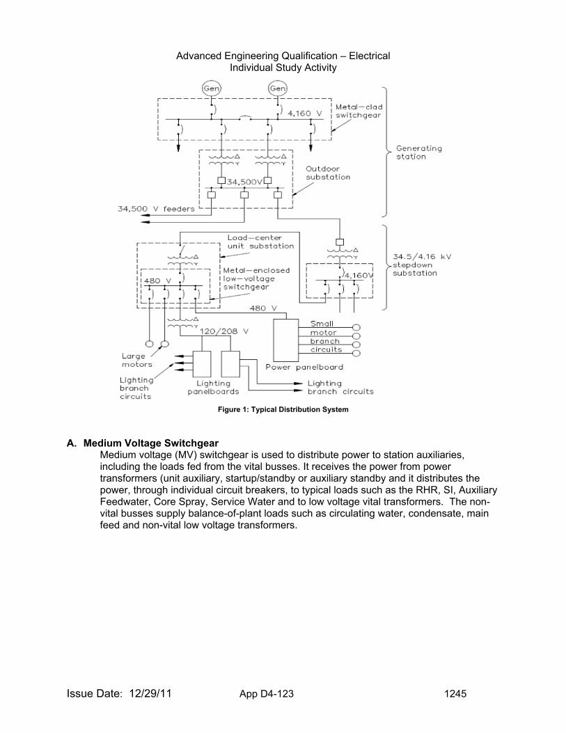
Advanced Engineering Qualification – Electrical Individual Study Activity
Issue Date: 12/29/11 App D4-123 1245
Figure 1: Typical Distribution System
A. Medium Voltage Switchgear
Medium voltage (MV) switchgear is used to distribute power to station auxiliaries, including the loads fed from the vital busses. It receives the power from power transformers (unit auxiliary, startup/standby or auxiliary standby and it distributes the power, through individual circuit breakers, to typical loads such as the RHR, SI, Auxiliary Feedwater, Core Spray, Service Water and to low voltage vital transformers. The non-vital busses supply balance-of-plant loads such as circulating water, condensate, main feed and non-vital low voltage transformers.
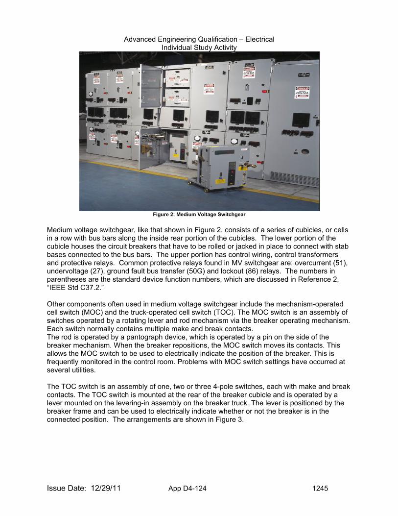
Advanced Engineering Qualification – Electrical Individual Study Activity
Issue Date: 12/29/11 App D4-124 1245
Figure 2: Medium Voltage Switchgear
Medium voltage switchgear, like that shown in Figure 2, consists of a series of cubicles, or cells in a row with bus bars along the inside rear portion of the cubicles. The lower portion of the cubicle houses the circuit breakers that have to be rolled or jacked in place to connect with stab bases connected to the bus bars. The upper portion has control wiring, control transformers and protective relays. Common protective relays found in MV switchgear are: overcurrent (51), undervoltage (27), ground fault bus transfer (50G) and lockout (86) relays. The numbers in parentheses are the standard device function numbers, which are discussed in Reference 2, “IEEE Std C37.2.” Other components often used in medium voltage switchgear include the mechanism-operated cell switch (MOC) and the truck-operated cell switch (TOC). The MOC switch is an assembly of switches operated by a rotating lever and rod mechanism via the breaker operating mechanism. Each switch normally contains multiple make and break contacts. The rod is operated by a pantograph device, which is operated by a pin on the side of the breaker mechanism. When the breaker repositions, the MOC switch moves its contacts. This allows the MOC switch to be used to electrically indicate the position of the breaker. This is frequently monitored in the control room. Problems with MOC switch settings have occurred at several utilities. The TOC switch is an assembly of one, two or three 4-pole switches, each with make and break contacts. The TOC switch is mounted at the rear of the breaker cubicle and is operated by a lever mounted on the levering-in assembly on the breaker truck. The lever is positioned by the breaker frame and can be used to electrically indicate whether or not the breaker is in the connected position. The arrangements are shown in Figure 3.
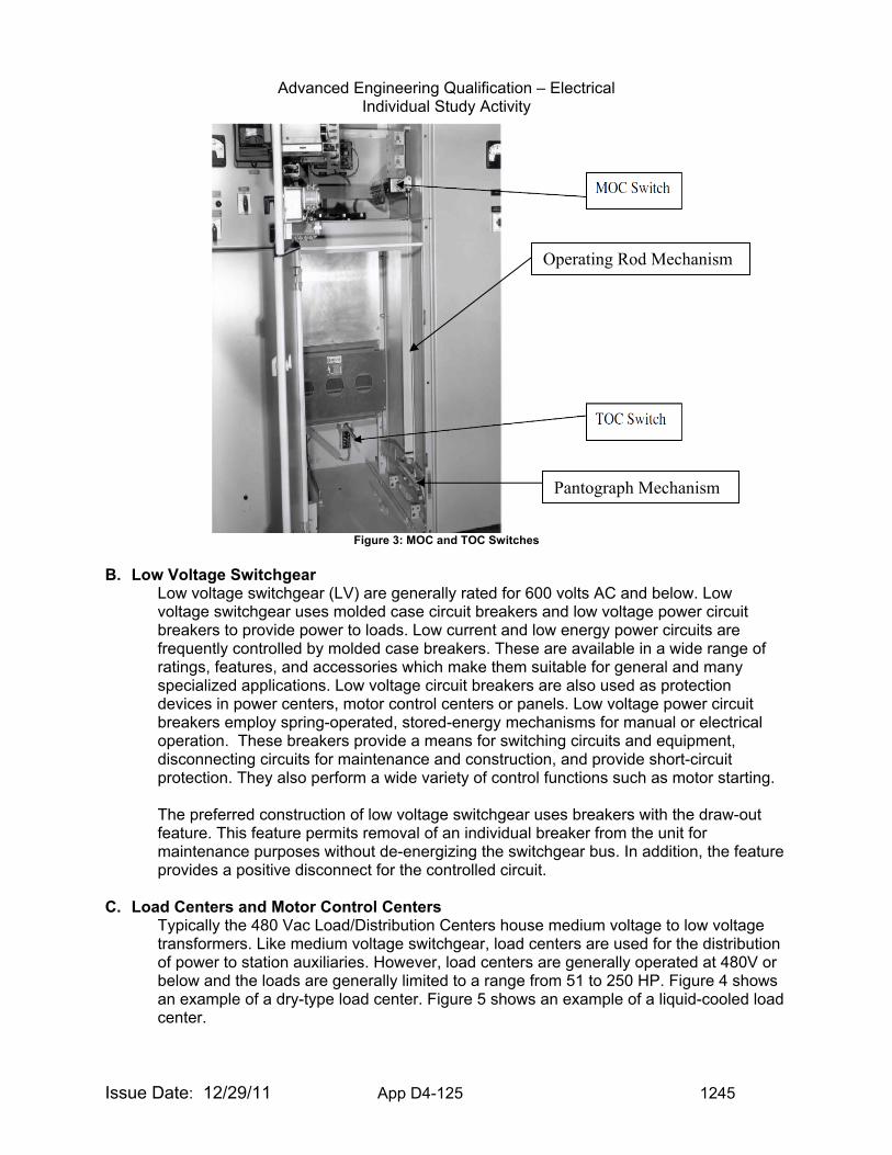
Advanced Engineering Qualification – Electrical Individual Study Activity
Issue Date: 12/29/11 App D4-125 1245
Figure 3: MOC and TOC Switches
B. Low Voltage Switchgear
Low voltage switchgear (LV) are generally rated for 600 volts AC and below. Low voltage switchgear uses molded case circuit breakers and low voltage power circuit breakers to provide power to loads. Low current and low energy power circuits are frequently controlled by molded case breakers. These are available in a wide range of ratings, features, and accessories which make them suitable for general and many specialized applications. Low voltage circuit breakers are also used as protection devices in power centers, motor control centers or panels. Low voltage power circuit breakers employ spring-operated, stored-energy mechanisms for manual or electrical operation. These breakers provide a means for switching circuits and equipment, disconnecting circuits for maintenance and construction, and provide short-circuit protection. They also perform a wide variety of control functions such as motor starting. The preferred construction of low voltage switchgear uses breakers with the draw-out feature. This feature permits removal of an individual breaker from the unit for maintenance purposes without de-energizing the switchgear bus. In addition, the feature provides a positive disconnect for the controlled circuit.
C. Load Centers and Motor Control Centers
Typically the 480 Vac Load/Distribution Centers house medium voltage to low voltage transformers. Like medium voltage switchgear, load centers are used for the distribution of power to station auxiliaries. However, load centers are generally operated at 480V or below and the loads are generally limited to a range from 51 to 250 HP. Figure 4 shows an example of a dry-type load center. Figure 5 shows an example of a liquid-cooled load center.
Operating Rod Mechanism
Pantograph Mechanism
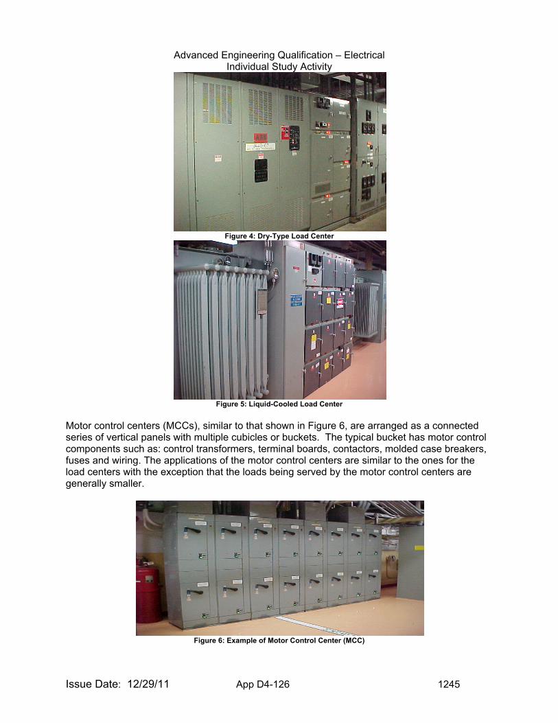
Advanced Engineering Qualification – Electrical Individual Study Activity
Issue Date: 12/29/11 App D4-126 1245
Figure 4: Dry-Type Load Center
Figure 5: Liquid-Cooled Load Center
Motor control centers (MCCs), similar to that shown in Figure 6, are arranged as a connected series of vertical panels with multiple cubicles or buckets. The typical bucket has motor control components such as: control transformers, terminal boards, contactors, molded case breakers, fuses and wiring. The applications of the motor control centers are similar to the ones for the load centers with the exception that the loads being served by the motor control centers are generally smaller.
Figure 6: Example of Motor Control Center (MCC)
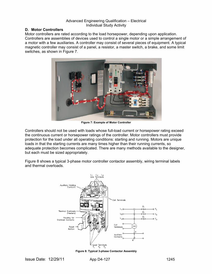
Advanced Engineering Qualification – Electrical Individual Study Activity
Issue Date: 12/29/11 App D4-127 1245
D. Motor Controllers Motor controllers are rated according to the load horsepower, depending upon application. Controllers are assemblies of devices used to control a single motor or a simple arrangement of a motor with a few auxiliaries. A controller may consist of several pieces of equipment. A typical magnetic controller may consist of a panel, a resistor, a master switch, a brake, and some limit switches, as shown in Figure 7.
Figure 7: Example of Motor Controller
Controllers should not be used with loads whose full-load current or horsepower rating exceed the continuous current or horsepower ratings of the controller. Motor controllers must provide protection for the load under all operating conditions: starting and running. Motors are unique loads in that the starting currents are many times higher than their running currents, so adequate protection becomes complicated. There are many methods available to the designer, but each must be sized appropriately. Figure 8 shows a typical 3-phase motor controller contactor assembly, wiring terminal labels and thermal overloads.
Figure 8: Typical 3-phase Contactor Assembly
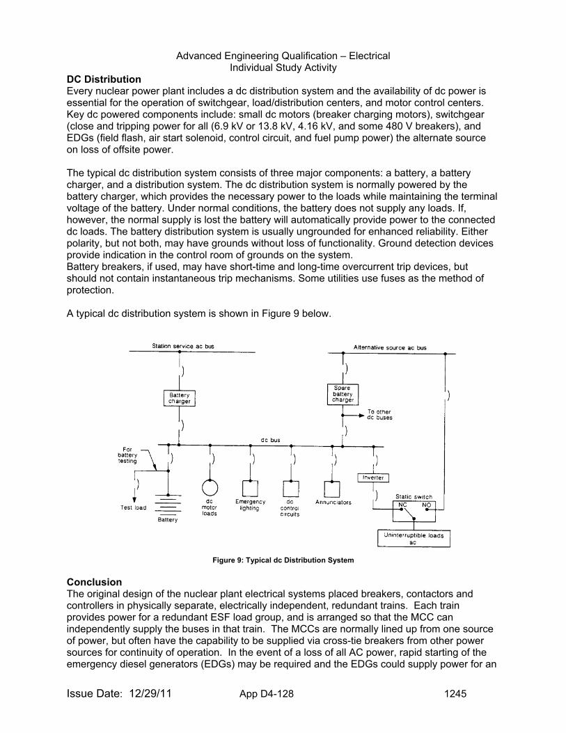
Advanced Engineering Qualification – Electrical Individual Study Activity
Issue Date: 12/29/11 App D4-128 1245
DC Distribution Every nuclear power plant includes a dc distribution system and the availability of dc power is essential for the operation of switchgear, load/distribution centers, and motor control centers. Key dc powered components include: small dc motors (breaker charging motors), switchgear (close and tripping power for all (6.9 kV or 13.8 kV, 4.16 kV, and some 480 V breakers), and EDGs (field flash, air start solenoid, control circuit, and fuel pump power) the alternate source on loss of offsite power. The typical dc distribution system consists of three major components: a battery, a battery charger, and a distribution system. The dc distribution system is normally powered by the battery charger, which provides the necessary power to the loads while maintaining the terminal voltage of the battery. Under normal conditions, the battery does not supply any loads. If, however, the normal supply is lost the battery will automatically provide power to the connected dc loads. The battery distribution system is usually ungrounded for enhanced reliability. Either polarity, but not both, may have grounds without loss of functionality. Ground detection devices provide indication in the control room of grounds on the system. Battery breakers, if used, may have short-time and long-time overcurrent trip devices, but should not contain instantaneous trip mechanisms. Some utilities use fuses as the method of protection. A typical dc distribution system is shown in Figure 9 below.
Figure 9: Typical dc Distribution System
Conclusion The original design of the nuclear plant electrical systems placed breakers, contactors and controllers in physically separate, electrically independent, redundant trains. Each train provides power for a redundant ESF load group, and is arranged so that the MCC can independently supply the buses in that train. The MCCs are normally lined up from one source of power, but often have the capability to be supplied via cross-tie breakers from other power sources for continuity of operation. In the event of a loss of all AC power, rapid starting of the emergency diesel generators (EDGs) may be required and the EDGs could supply power for an
Advanced Engineering Qualification – Electrical Individual Study Activity
Issue Date: 12/29/11 App D4-129 1245
extended period of time. In either case, it is essential that the batteries and load sequencers function properly if the plant safety systems are to operate as required. Examples of Findings for Switchgear, Load/Distribution Centers, Motor Control Centers and Controllers:
• When a pump was started remotely from the control room following mechanical maintenance on the pump, a fault internal to Motor Control Center associated with a load breaker resulted in damage to the associated vertical bus bar and a fire at the MCC that self extinguished.
• Safety related Motor Control Centers (MCCs) were located in the auxiliary building where a design bases event could created an accident temperature (LOCA or HELB) that exceeded the design temperature limit of the MCCs.
Walkdown Inspection Things to Look For On Switchgear, Load/Distribution Centers, Motor Control Centers and Controllers:
1. The panel doors bolts are engaged and door is not free to open. 2. Flooding sources such as pipes that could break would not allow water to flood up to the
level of the lowest cubicles. Determine what loads are in the lowest cubicles. 3. Cubicles should not have holes where water could enter. Hardware that is badly
corroded should be replaced. 4. Breakers are in the correct position; use the operator’s normal lineup sheets and that
labels on the different cubicles agree with the wording on the lineup sheets and drawing descriptions of components in each cubicle.
5. Cabling should not violate the minimum bend radius specified in the manufacturer’s cable specifications.
6. If MCC breakers and/or fuses must be repositioned/removed during loss of power, are emergency lights adequately pointed to perform that task (pay particular attention to Appendix R emergency lights)?
7. Planned maintenance outages of MCCs could de-energize the normal source of power to Appendix R emergency lighting and could affect the reliability of the emergency lighting’s battery. For example, Appendix R emergency lighting is designed with batteries capable of supplying emergency lighting for 8-hours without causing damage to the batteries upon a loss of ac power. Maintenance on MCCs that supply ac power to emergency lights that is scheduled to take longer than 8-hours could result in excessive discharge of the batteries on the Appendix R emergency lights.
Examples of Information to Request for Inspection of AC Power Distribution Issues: For any inspection to be successful the inspector must request the right information to evaluate whether the licensee is correctly interpreting and applying requirements, industry standards, lessons learned and industry best practices. Typical sample requests would be
• vendor manuals and maintenance procedures, • wiring diagrams and schematics, • load lists and loading calculation, • short circuit calculations, • completed construction tests or surveillance tests, • coordination guidance and coordination diagrams.
Training associated with Switchgear, Load/Distribution Centers, Motor Control Centers and Controllers:
Advanced Engineering Qualification – Electrical Individual Study Activity
Issue Date: 12/29/11 App D4-130 1245
Motor Controls and Starters EVALUATION CRITERIA: Upon completion of the tasks in this guide, you will be asked to demonstrate your
understanding of switchgear, load/distribution centers, motor control centers and controllers in electrical power distribution systems by performing the following:
1. Discuss the typical loads for medium voltage switchgear, the typical loads for low voltage
load centers, and the typical loads for MCC circuits. 2. Describe the normal maintenance performed on the Switchgear, Load/Distribution
Centers and MCCs. 3. Discuss surveillances that are performed on the switchgear, load/distribution centers and
MCCs. 4. Discuss the calculations associated with the medium voltage and low voltage systems to
assure operability during worst case accident conditions. 5. Explain what effect cable resistance has on voltage at the load and what effect voltage
level would have on a motor start. 6. Discuss a) the Mechanism Operated Cell switch (MOC) and its function, and b) the
Truck Operated Cell switch (TOC) and its function. TASKS:
1. Read the references and discussion sections in sufficient detail to perform adequately in accordance with the requirements of the evaluation criteria.
2. Read and understand UFSAR (Section 8, Electric Power) for PWR and BWR designs. 3. Read and understand Technical Specifications (Section 3. 8. x, Electric Power) for PWR
and BWR designs (See also NUREG 1431, Standard Technical Specifications Westinghouse Plants, NUREG 1432, Standard Technical Specifications Combustion Engineering Plants, NUREG 1433, Standard Technical Specifications General Electric Plants, BWR/4, NUREG 1434, Standard Technical Specifications General Electric Plants, BWR/6).
4. Meet with your supervisor, or the person designated to be your resource for this activity, and discuss the answers to the questions listed under the evaluation criteria.
5. Familiarize yourself with the inspection resources listed under the Operational Experience website.
6. Familiarize yourself with the documentation necessary to perform inspections of switchgear, load centers, MCCs, and controllers in electrical distribution systems.
DOCUMENTATION: Advanced Engineering Qualification – Electrical Signature Card Item ISA-
EE-14
Advanced Engineering Qualification – Electrical Individual Study Activity
Issue Date: 12/29/11 App D4-131 1245
TOPIC: (ISA-EE-15) Electrical Power Grid PURPOSE: The purpose of this guide is to acquaint the reader with basic concepts
related to the electric power grid. It should be recognized that this subject is vast, and a complete understanding of power grid operation would take years of study and experience. The Evaluation Criteria section below is a reproduction of a white paper edited by Paul J. Fillion, an inspector in Region II, in 2001, which was intended to be primer on the grid for both electrical and non-electrical inspectors as well as mangers. The paper borrows heavily and frequently extracts passages from the listed references. It is hoped that this activity will serve as a starting point to understanding the electric power grid.
COMPETENCY AREA: INSPECTION LEVEL OF EFFORT: As determined by Branch Chief or supervisor. REFERENCES: Contained in the Discussion Section DISCUSSION: The traditional model of electric power generation and delivery is based on the construction of large, centrally located power plants. “Central,” in this case, ideally means that the power plants are located on hubs surrounded by major electrical load centers. Regardless of where power plants are located, their power must be brought from the plant to the users, and that’s the purpose of the electricity grid. The grid consists of two infrastructures: the high-voltage transmission systems, which carry electricity from the power plants and transmit it hundreds of miles away, and the lower-voltage distribution systems, which draw electricity from the transmission lines and distribute it to individual customers. The NRC is interested in the electric grid because it is the preferred source of power for safety-related systems at nuclear power plants. At present, major operational changes are taking place while the physical capacity of the grid is stretched thin. There is a need for inspectors of electrical systems and managers to stay abreast of this situation. Therefore, Engineering Branch in Region II has studied and summarized numerous articles published in IEEE Spectrum magazine since 1989, and other sources, which discuss the current state of the grid. This paper explains some basic principles of grid operation, summarizes the history of electric market restructuring, gives some insight into how a competitive market would work, briefly discusses lessons learned from recent major blackouts and finally, summarizes NRC activity in these areas. Basic Concepts and Facts Everybody in modern society knows that the purpose of the electric grid is to generate and transmit electric power to locations where it will be consumed by machines and devices. The majority of the generated and transmitted power does useful work in the scientific sense like turn a fan or gets converted into a useful form of energy like heat. Not so widely understood, is the concept of reactive power. A major portion of the machines and devices powered by the grid involve motors and transformers, which work by creating a magnetic field. A component of the electric power goes to creating and maintaining the magnetic field, and is called reactive power. So the total power transmitted by the grid is composed of 1) real power which does
Advanced Engineering Qualification – Electrical Individual Study Activity
Issue Date: 12/29/11 App D4-132 1245
useful work and, 2) reactive power which gets stored in magnetic fields. The unit of real power is the Watt and the unit of reactive power is VAR, which stands for volts-amperes-reactive. Reactive power can be generated by several different methods: generators, shunt capacitor banks, static VAR compensators and synchronous compensators. Real power and reactive power are measured by different types of meters and they behave differently when being transmitted over the grid. In general, reactive power will cause more voltage drop when transmitted over a line than an equal amount of real power. Transmitting reactive power over long distances tends to create voltage problems at the receiving end. Voltage can be improved by installing capacitor banks at the receiving end, allowing generators near the load to supply the VARs, installing series capacitors or transformer load tap-changers. The amount of power transmitted over lines in the grid has been increasing since at least 1983 for two reasons. First, long distance transmission can take advantage of low cost fuel. In other words, the big loads are urban centers, but generators using low cost fuel like coal must be located a considerable distance away. Second, a byproduct of restructuring is that more power is being transmitted longer distances. TVA had 20,000 requests to transmit power through its grid in 1996 and 300,000 requests in 1999. This complicates the job of grid operators and designers. The voltage drop caused by reactive power transmission is the main reason why direct current (DC) transmission lines were built to transmit large blocks of power over long distances. DC power is all real power; there is no reactive component. In some cases engineering economics studies show that the a DC transmission line requiring power conditioning equipment at each end to convert from alternating current (AC) to DC and visa versa cost less than a traditional AC transmission line. Another distinctive characteristic of an AC electric circuit is that for a complicated circuit - and the grid is a very complicated circuit - the path that current (and power) will take is difficult to predict. For example, Consolidated Edison in New York City often imports power from Canadian hydroelectric plants. Contracts call for the power to come around Lake Erie and Lake Ontario in a clockwise direction and down through New York State. But sometimes as much as 60 percent of the power would take a different route, counterclockwise around Lake Erie through Ohio, Pennsylvania, and into southeastern New York. Therefore, utilities not involved in the transaction would see their operations disrupted by power flowing through their system. Phase shifting transformers and series compensation capacitors can help correct this problem by allowing operators to nudge power flow in the desired direction. So, the big picture is that the transmission part of the grid, which has not expanded much over recent years, is being asked to carry more and more power. The increased load on the transmission lines, operating at 230 kV, 345 kV, 500kV and 765 kV, plus DC, is the result of a desire of large consumers to obtain the cheapest power available (in a deregulated world) and more recently, a necessity to keep the lights on in urban areas where local power can no longer meet peak demand. Con Edison in New York depends on Ontario Hydro; the Mid-Atlantic States depend on American Electric Power in Ohio, and Boston Edison imports power from other states. Portions of the grid can and have become congested to the point where additional load flows have to be prohibited by system operators to maintain grid stability. Capacity to transport power over long distances is limited by thermal capacity of lines (line sag), frequency stability and the supply of reactive power. As we look to the future, it may be helpful to develop new computer-based visualization tools to allow the grid operators to see the congestion points in more intuitive ways.
Advanced Engineering Qualification – Electrical Individual Study Activity
Issue Date: 12/29/11 App D4-133 1245
The North American power system consists of four huge semi-distinct interconnections linked and buffered by DC tie lines: Eastern, Western, Texas and Quebec. The North American Electric Reliability Council (NERC), which was created after the 1965 blackout in the Northeast, divides the whole system into ten reliability councils. NERC which is based in Princeton, N.J., publishes annual and seasonal “Reliability Assessments” detailing the status of electricity supply and transmission capabilities. After power failures in the summer of 1996, NERC developed Operating Standards which specify best engineering practice in many areas affecting the dynamic performance and reliability of power systems. Two hundred investor-owned utilities deliver 70 percent of the power. Three thousand municipal power companies purchase power wholesale, and the largest of these generate power. The Federal Government also owns utilities. The above discussion used the term megawatt as the unit of electric power. To help put this quantity in perspective, it is useful to think in terms of how many homes can be supplied by one megawatt. Actually, there is no single answer to this question. One megawatt of generation can supply somewhere between 600 to 1000 homes depending on the demand factor which in turn varies with geographical location, season, and with temperature. Another concept to understand is that electric power cannot presently be stored in any meaningful quantity. Electric power must be generated as it is being used. Generation must always match the load. History and Status of Restructuring The zeitgeist for a century was that the electric power industry was a natural monopoly, and for good reason. The vertically integrated monopoly concept enabled the building of large scale efficient power plants and transmission grids. The concept allowed many worthy objectives to be fulfilled: electrification of poor and rural areas, development of diverse indigenous fuels and diverse types of generating plants, environmental safeguarding, reliability of service, and price stability. The 1935 Public Utility Holding Company Act set up a national regulatory system of vertically integrated monopolies serving captive markets. Utilities had to serve all existing and future customers within their territories while operations and rates were state regulated. Eventually thinking began to change. Technology imported from materials science and the space program enabled the building of very efficient gas turbines. At the same time, the price of gas declined, and the prohibitions on gas burning were repealed. Driven by pressure from large industrial consumers looking for cheaper power, the concept of “unbundling” the generation, transmission and distribution parts of the electric power industry came to the fore. A system of transactions was visualized. Another technology, computers, matured to the point where the informational requirements and numerous transactions of a free market could be handled. The July 1978 issue of IEEE Spectrum contained an article by Fred C. Schweppe of the Massachusetts Institute of Technology wherein he predicted that minicomputers would soon enable utilities to buy and sell power at real-time rates set by supply and demand. Electric power industry restructuring really began in the United States in 1978 with the Public Utilities Regulated Policies Act (PURPA), which calls for competition in generation. The Act specified that utilities must purchase power from independent producers at price of “avoided cost.” Independents thrived demonstrating that competition could work. From the customer viewpoint, the utility became the sole designated purchasing agent allowed to buy power from the independent producers. Contracts between utilities and independent producers at this time were long term contracts, there was no spot market. We were some time away from giving customers a choice of who would supply them. PURPA was really motivated by a desire to
Advanced Engineering Qualification – Electrical Individual Study Activity
Issue Date: 12/29/11 App D4-134 1245
encourage new and alternative means of generation. The Energy Policy Act of 1992 envisioned a system of wholesale competition where 3000 plus utilities become distributors to residential and large customers. Some states believe this means a “player” must be either a distributor or a generator. Traditional utilities divest themselves of generators to become distributors. The transmission system is open access. So there is considerable competition in a market of many purchasing agents (distributors) and many generators. On the other hand, in Virginia and Pennsylvania for example, one company can be both a generator and a distributor. The Act allows individual states to determine whether they want competition on the retail level. One version of this is that some large customers are allowed to make contracts directly with generators. This immediately creates a problem of definition. Teams of lawyers can spend a long time handling disputes as to which entity is (or is not) a large customer. It raises the question for example could a subdivision aggregate their load and apply for large customer status. In 1994, California adopted a system called “direct access” where even residential customers can choose which generator will supply their power. The Federal Energy Regulatory Commission (FERC) approved “stranded-cost” recovery in March 1995, although this issue is heated and far from settled. FERC Order No. 888, issued in 1996, established rules for wholesale and retail competition. The Order mandated open and equal access to the transmission grid for all buyers and sellers of wholesale electricity. The Order also established eleven criteria for Independent System Operators (ISOs). FERC Order No. 889, also issued in 1996, mandated the use of an internet bulletin boards system called Open Access Same-Time Information System (oasis) to enable the competitive market by making known the available transmission capability on a real time basis. In December 1999 FERC Order No. 2000 established Regional Transmission Operators (RTO). The need for and role of ISOs and RTOs will be discussed in the next section. The current status of restructuring is complicated since each state has its own timetable. The most aggressive restructuring took place in states with the highest electricity cost. It is well known that California was quick to restructure and quick to have major problems. Large consumers were the driving force. Initially, politicians, consumer watchdog groups and small consumers endorsed the idea. The reasons for California’s problems are varied, complex and to some extent obscured in finger pointing. It serves no good purpose to discuss the details of California’s problems with restructuring here. A few references are given which delve into this topic. Restructuring has also been a failure in many other countries. On the other hand, Pennsylvania provides a contrasting example of how restructuring can work. Details of Operation under Restructuring To restructure the grid, i.e. move from monopoly to competition, two entities must be invented and created: a system operator and a transactions manager. Although separate, these entities must work together closely. As stated previously, FERC Order No. 888 recognized the need for the system operator when it defined an Independent System Operator (ISO). The ISO manages electricity flows on the transmission grid and ensures stability of the grid. It has the authority to call on or call off a generating unit, regardless of any contracts between buyer and seller, to control frequency and voltage. The ISO secures ancillary services such as spinning reserve, non-spinning reserve, black-start capability, automatic generation control units, and determines how transmission losses will be met. The ISO performs other functions as well, which will be discussed in relation to managing the transactions market. The ISO’s primary responsibility is reliability of the grid. Their generation reliability target is failure to meet demand no more than one day in ten years. Traditionally this approach has required a reserve on the order of 10 to 15 percent, allowing for planned and forced outages. This target is basically a statistical measure
Advanced Engineering Qualification – Electrical Individual Study Activity
Issue Date: 12/29/11 App D4-135 1245
of need. Transmission reliability is designed deterministically. The system is designed to allow for the loss of any single element without subsequent loss of any other element while maintaining the remaining elements within their load carrying capacity. To help know whether the design is adequate, several reliability indexes are maintained. There is the system average interruption frequency index (SAIFI). There is the system average interruption duration index (SAIDI). There is the customer average interruption duration index (CAIDI). And there probably are other indexes. Managing transactions in a competitive world is also very complex. There may be several distinct markets: long and short term generating capacity and transmission markets, an auction for transmission rights and an ancillary services market. Within the generating and transmission capacity markets there could be three choices: self-scheduling, bilateral transactions and the spot market. The transactions manager, sometimes referred to as the Power Exchange, makes a day-ahead schedule of transactions for the buying and selling of power. The schedule is set and announced by 2:00 pm. This allows time for one iteration of the schedule before 12:00 am. The ISO analyzes the schedule, and if the ISO finds congestion, it informs the parties involved how it would eliminate congestion and at what price. For example, the ISO would call on generation at a particular location to alleviate the congestion, and these megawatts may be more expensive than the agreements comprising the schedule. Parties can then modify and resubmit their schedules. There is also an hour-ahead schedule prior to each hour. Should congestion arise, protocols and pricing mechanisms are in-place to manage the congestion. A congestion cost would be imposed on all parties transmitting over the previously congested path. NERC has developed a Transmission Information System and an Interchange Distribution Calculator. The Transmission Information System tags transactions with source, route and destination. This data is then fed into the Interchange Distribution Calculator which checks that the grid can handle the proposed loading within the reliability guidelines. NERC has also issued standards, compliance requirements and penalties, but at present these are voluntary. The DeLay-Markey Bill HR-4432 would make these mandatory if passed by Congress. The FERC developed oasis has already been mentioned. When one ponders the details of operation under a restructured grid, one begins to understand the added complexity as well as equipment and human stress that will be placed on the grid. Not to mention added cost. The California ISO and Power Exchange cost $400 million to set up. Who should own the open access grid is a key and controversial question. What incentive will exist for the owner to build the much needed additional capacity? It has already been realized that ISOs cover too small an area to really allow the real-time coordination between grid operations areas to achieve the reliability goals. That is why FERC Order No. 2000 introduced the concept of Regional Transmission Operators (RTOs) which will replace the ISOs and cover a much larger area. FERC Order No. 2000 sites PJM which is already in operation as a good example to follow when setting up a RTO. PJM was in operation well before grid restructuring, and the acronym originally stood for Pennsylvania, New Jersey and Maryland. It now covers all or part of Pennsylvania, New Jersey, Maryland, Delaware, Virginia and District of Columbia. The nucleus of PJM is just five people and five work stations in an underground bomb-proof control room in a nondescript building near Valley Forge, PA. There are two market transactions and scheduling coordinators, a generation coordinator (who balances demand and generation), a transmission grid coordinator (who provides real-time operation of the grid) and a shift supervisor. More controllers are on duty to help during periods of high demand or stress. Hundreds of employees are behind the scenes. Dominion-Virginia Power (Surry and North Anna) has joined Alliance Regional Transmission Organization which will be located in Ohio.
Advanced Engineering Qualification – Electrical Individual Study Activity
Issue Date: 12/29/11 App D4-136 1245
Blackouts, Voltage Reductions and their Causes The NRC has been concerned for some time about the adequacy of voltage following trips at nuclear power plants. From that perspective it is instructive to understand the causes for blackouts that occurred in recent years. Lessons learned from those events have applicability to calculations performed by transmission system engineers to determine the minimum expected voltage at nuclear plant switchyards. On July 2, 1996, there was a major blackout in the Northwest part of the United States. The situation immediately before the outage was that near maximum expected power was being transmitted from the Pacific Northwest to California. This power flowed long distances over a weakly meshed grid, since it crossed areas of low population. Problems began with flashover of a 345 kV line to a tree. This type of fault is more likely to happen on a heavily loaded line on a hot day because as the temperature of the conductors increases the line sag. At the same time faulty operation of a ground fault relay tripped a parallel 345 kV line. While this would not have occurred if the relay had an optimum set point, it does take very careful analysis to set relays protecting parallel lines such that they can discriminate faults on the other line. Twenty-four seconds after the fault several smaller hydro units started to trip due to high reactive output. Loss of the two 345 kV lines caused the remaining lines to become overloaded and lines tripped in a cascading fashion. Finally, the system broke into five islands and 11,743 MW of load was lost. On August 10, 1996, there was another major blackout in the Northwest. Again there was a high level of power transfers from the Northwest to California. Again trouble started with flashover of a line to a tree. This time it was a 500 kV line. The line was lightly loaded, but its capacitance was lost which affected voltage on the system. A second flashover of a 500 kV line to a tree occurred. The subsequent voltage depression together with improper voltage control at three power plants contributed to voltage decaying from 540 kV to 504 kV. Again, the transmission line outages overloaded parallel lower voltage lines. About five minutes later, a relay failure tripped a 115 kV line, and a 230 kV line sagged into a tree also tripping. About the same time hydro units started tripping because of faulty relays, which further reduced voltage and caused further system stress. Oscillations soon caused synchronous instability. The system broke into four islands and 30,489 MW of load was lost. During the summer of 1998, a prolonged heat wave in the Northeast and Midwest sent demand soaring beyond projections. At several New England utilities, voltage had to be reduced 12 times. These voltage reductions were due to lack of reactive power at critical locations. That summer’s heat wave was accompanied by spikes in the wholesale price in the Midwest. In 1999, there were local blackouts and brownouts in New England, New York, Chicago, mid-Atlantic and South-Central states. Some of the lessons learned from these failures are: • Power systems were not adequately studied. They were operating in a condition where
loss of a line led to cascading. As previously stated, this is not allowed by the design criteria.
• Generators should not be allowed to automatically supply reactive power demands until they trip, but rather it would be better if overexcitation was limited.
• There were relay design and set point problems. • Fast load shedding and fast capacitor banks could have alleviated the severity of the
problems. These have now been added. • Interaction between the AC and DC systems was not modeled in system studies. • The power system stabilizers at nuclear power plants were turned off. • Many problems in simulation programs were identified concerning the reactive power
Advanced Engineering Qualification – Electrical Individual Study Activity
Issue Date: 12/29/11 App D4-137 1245
capability. The generators could not actually produce the amount of reactive power assumed in the simulations. Validation of the system modeling is now required.
• Planning was not based on the heat/humidity derated value of generator capacity. • System operators had trouble obtaining voltage support because there was no economic
incentive. • On the local level lack of maintenance and system degradation resulted in blackouts. In
New York City, blackouts were due to problems with underground cables. The duct lines and manholes are a harsh environment because people illegally dump oil and chemicals into the manholes. Also, in a prolonged heat wave the ground temperature increases causing the cable temperature to increase at a time when load demand is high or above forecasted levels. On July 6, 1999, 8 of 14 feeder cables failed.
NRC and Industry Activity Both the NRC and the power industry are concerned about reliability of the grid. Concern is justified for at least three reasons. Projections by the North American Electric Reliability Council (NERC) show that capacity margins are shrinking. A 1998 NERC study projected that capacity margins at peak load will shrink to less than 10 percent in the Eastern interconnection by 2004 and in the Western connection by 2007. As stated previously, a margin of 10 to 15 percent was considered necessary to maintain the reliability goals. In the 1980s, the capacity margin was 20 - 30 percent. Margin refers to generation capacity versus load demand. It does not account for the transmission line bottlenecks that exist. Theoretically, lack of margin does not lead to instability; it leads to controlled blackouts and brownouts. But nevertheless, a heavily loaded grid is probably less reliable than a grid operating well within its capacity. The second reason is that, as described above, major operational changes are being made at a time when physical and human resources are stretched to the limit. No doubt current challenges will be solved by technology and improved market structure, but there could be an interim period of problems. Third, lessons learned from recent outages cast some doubt on the accuracy of grid computer simulations upon which the nuclear plant GDC-17 calculations are ultimately based. Focusing on the second of these factors, the NRC has issued SECY-99-129, “Effects of Electric Power Industry Deregulation on Electric Grid Reliability and Reactor Safety.” The NRC did quite a lot of review and research for this paper, and it is backed up by a report by Oak Ridge National Labs. The conclusion in that paper is that the risk increase associated with deregulation is low. Nevertheless, there are some issues that are being addressed by NEI and INPO initiatives, which are being monitored by NRC staff. In December 2000, the NRC issued Regulatory Issue Summary 2000-24, “Concerns about Offsite Power Voltage Inadequacies and Grid Reliability due to Industry Deregulation.” This document gives good background information, summarizes the issues, and lists four NEI action items. Each plant should be reviewing the plant/grid interface and taking steps as appropriate to minimize degraded voltage from occurring. The NRC staff has established ongoing communications with NERC, FERC and DOE to discuss grid reliability trends important to nuclear power plant operation; and the NRC staff monitors grid operations on a daily basis. John F. Hauer of the Pacific Northwest National Laboratory, a leading expert on the Western grid system and a member of the Post Outage Study Team for the 1996 outages, wrote a white paper in 2000 on reliability issues and system events for DOE’s Office of Power Technologies. EPRI launched a first-ever evaluation of the whole US power system employing the techniques of probability risk assessment refined in studies of nuclear power supply. In August 2004, a Memorandum of Agreement (MOA) was established between NRC and
Advanced Engineering Qualification – Electrical Individual Study Activity
Issue Date: 12/29/11 App D4-138 1245
NERC. The MOA and its companion Appendices can be found in the Agencywide Documents Access and Management System (ADAMS) at accession numbers ML0425203290 (for the MOA) and ML051750337 (for the Appendices). The MOA and the accompanying four appendices provide for the following:
• Appendix I – Coordination plan for communications and information sharing during emergencies.
• Appendix II – Coordination plan for event analysis and follow-up review activities. • Appendix III – Coordination plan for the exchange of operational experience data and
information. • Appendix IV – Coordination plan for participation by NRC staff in NERC committee and
subgroup activities. References Palmer,R.E., Burchett, R.C., Happ, H.H., Vierath, D.R., “Reactive Power Dispatching for Power System Voltage Security”, Paper No. 83 SM 341-5, IEEE/PES 1983 Summer Meeting, Los Angeles, California. Articles Published in the IEEE Spectrum Magazine:
August 1989, “Moving Power Through the Northeast Corridor” by Glenn Zorpette, Associate Editor.
July 1996, “Unlocking the Grid” by Sally Hunt and Graham Shuttleworth, National Economic Research Associates, Inc.
July 1996, “Charting a New Course in California” by Barbara R. Barkovich and Dianne V. Hawk, Barkovich & Yap, Inc.
June 1999, “Keeping the Lights On” by John D. Mountford and Ricardo R. Austria, Power Technologies, Inc. June 1999, “Improving Grid Behavior” by Carson W. Taylor, Bonneville Power Administration.
June 2000, “Restructuring the Thin-Stretched Grid” by William Sweet, Senior Editor.
June 2000, “PJM Interconnection: Model of a Smooth Operator” by Elizabeth A. Bretz, Senior Associate Editor.
February 2001, “Electricity Troubles in California: Who’s Next” by Marija Ilic, Petter Skantze and Poonssaeng Visudhiphan, Energy Laboratory Massachusetts Institute of Technology.
February 2001, “California’s Electricity Crisis Rooted in Many Failings” by Jason Makansi.
February 2001, “Visualizing the Electric Grid” by Thomas J. Overbye, University of Illinois, and James D. Weber, Power World Corp.
February 2001, “A Brief History of the Power Flow” by Fernando L. Alvarado, University
Advanced Engineering Qualification – Electrical Individual Study Activity
Issue Date: 12/29/11 App D4-139 1245
of Wisconsin, and Robert J. Thomas, Cornell University.
June 2001, “Technology Offers Solutions to the Current Power Crisis” by Karl Stahlfopf, Vice President, Power Delivery, Electric Power Research Institute.
June 2001, “Electricity Restructuring in Britain: Not a Model to Follow” by Theo MacGregor, MacGregor Energy Consultancy.
June 2001, “Putting Consumers First” by Glenn English, National Rural Electric Cooperative Association.
July 2001, “Energy Woes” by William Sweet, Senior News Editor, and Elizabeth A. Bretz, Senior Associate Editor. Also includes excerpts from the “National Energy Policy Report”, issued May 16, 2001, and “Clean Energy Scenarios” which gives a contrasting view.
Articles published in Time Magazine:
July 17, 2000, “Power’s Surge” by Daniel Eisenberg. Article about deregulation.
January 29, 2001, “The New Energy Crunch.” A related set of four articles by various authors on deregulation in general.
February 19, 2001, “Watt Friends We Have” by Stephen Handelman. How Canadian Power Plants profited from the California energy crisis.
USA Today, February 8, 2001, “When Energy Prices Go Up Some Businesses Turn Off” by Byron Acohido. How “real-time pricing” has been working well in Georgia for some time. The Boston Globe, August 11, 2001, “Power Grid Takes Heat” by Peter J. Howe. About the electric power situation in Boston during the August 2001 heat wave. The Baltimore Chronicle & Sentinel, August 1, 2001, “California Energy Saga Continues” by Natasha Papousek. SECY-99-129, “Effects of Electric Power Industry Deregulation on Electric Grid Reliability and Reactor Safety,” issued May 11, 1999. NRC Regulatory Issue Summary 2000-24, “Concerns About Offsite Power Voltage Inadequacies and Grid Reliability Challenges Due to Industry Deregulation,” issued December 21, 2000. Paper, “Adequacy of Nuclear Station Electrical Distribution System Voltages” by Paul J. Fillion, Reactor Inspector, and edited by Jeffery D. Main, Publications Branch, dated November 3, 1995. Electrical World Magazine, T&D Edition, October 1996, Special Report [on the electric grid]. Examples of Event Reports to Review for Grid Related Issues: 44234 Millstone Reactor trip due to a grid disturbance caused by lightning strike.
Advanced Engineering Qualification – Electrical Individual Study Activity
Issue Date: 12/29/11 App D4-140 1245
44227 San Onofre The offsite power grid frequency dipped to approximately 59.69 hertz.
44009 Turkey Point Both units tripped due to a momentary power fluctuation caused by grid instabilities.
43050 Three Mile Island
Reactor trip due to grid disturbance.
42310 San Onofre Offsite power not within specifications. The Grid Control Center notified San Onofre that the grid nomograms predicted offsite power would not be within limits if San Onofre Unit 3 were to trip.
41741 Oyster Creek The licensee reported that an offsite electrical transient on the 230 kV transmission line appears to have caused a generator trip and corresponding turbine trip and reactor scram.
41113 Wolf Creek Wolf Creek Generating Station experienced a loss of the west bus in the switchyard causing a loss of power to the Startup Transformer and the ‘B’ Train 4.16 kV ESFAS Bus NB02.
40818 San Onofre Licensee declared offsite power inoperable due to dip in grid frequency. Grid frequency dipped to about 59.7 hertz or slightly lower, and then recovered about three minutes later.
40814 Palo Verde On June 14, 2004, all three units experienced automatic reactor trips coincident with a grid disturbance and loss of offsite power in the Palo Verde Switchyard.
39337 Nine Mile Point Power Control’s load flow computer program that monitors the 115 kV Grid for NMP1, determined that there was insufficient voltage (based on the grid loading) to supply NMP1 ECCS loads during a LOCA.
37325 Grand Gulf Automatic scram due to electrical grid disturbance. A Baxter Wilson Station 500 kV breaker opened inducing a grid disturbance that caused a reactor scram for an unknown reason.
Examples of Findings for Grid Related Problems: Indian Point – A Green self-revealing finding involving the failure of a 345 kV circuit breaker No.3. The NRC determined that poor maintenance work practices and insufficient contractor oversight contributed to the self-revealing finding. (IR 05000247/2003013 and 05000286/2003010) Indian Point - A Green finding for inadequate corrective actions for repeat Unit 2 reactor scrams attributed to grid-related faults and associated protective relaying failures. (IR 05000247/2003013 and 05000286/2003010) Nine Mile Point – A Green finding was identified was identified for corrective actions associated with the 115 kV offsite power sources. The licensee allowed a line to be taken out of service for maintenance even though an estimator program had determined that the grid voltage would drop below the contingency voltage (i.e. below the minimum voltage required to prevent separation of the emergency buses from the grid in the event of a design basis accident). (IR 05000220/2003004 and 05000410/2003004) Summer - A Green finding was identified because the licensee’s Transient Stability Study of the Offsite Power System identified that under certain grid conditions (the transmission system lightly loaded, the Fairfield Pumped Storage Plant operating in the pumping mode at ½ or more of its rated capacity, and a fault on the 230 kV offsite power bus) a loss of offsite power (LOSP)
Advanced Engineering Qualification – Electrical Individual Study Activity
Issue Date: 12/29/11 App D4-141 1245
could occur. The licensee’s probabilistic risk assessment (PRA) screening analysis of the grid conditions described above showed that there would be a slight increase in the LOSP initiation frequency resulting in a change in the core damage frequency (CDF) of less than 1.0 X 10⁻⁶. (IR 05000395/2000003) Kewanee – A Green finding was identified for a NCV of 10 CFR Part 50.65 (a) (4) for failure to adequately assess shutdown risk during degraded grid conditions. (IR 05000305/2005008) Perry – A Green NCV of Tech Spec 5.4.1.a was identified for failure to follow procedures while paralleling to the grid. (IR 05000440/2002005) River Bend – The specified minimum voltage on the ac buses used to calculate equipment operability was based on an assumption of 95 percent nominal voltage at the Fancy Point substation in lieu of the more limiting tech spec allowable value for the degraded grid voltage relays on the 4.16 kV buses. The tech spec bases stated that these relays were set high enough to ensure that sufficient power was available to the required equipment. However, design calculations did not exist to support this statement. The non-conservative voltage assumption resulted in overestimating the minimum voltage available for motor-operated valves and other loads on the safety-related 480 Vac buses. This discrepancy was identified as a Green NCV of 10 CFR 50, Appendix B, Criterion III, “Design Control.” Examples of Information to Request for Inspection of Grid Issues: The inspector should review the processes used by the utility and the regional transmission organization to communicate current and projected grid conditions, switchyard maintenance activities, and nuclear plant maintenance. This should include a review of risk management actions including restrictions on maintenance activities during high-risk conditions, e.g., peak demand periods. The inspector should review historical data for grid-related loss of offsite power events for the past 20 years at the site. The inspector should review the plant processes and procedures for monitoring grid and safety-related bus voltages during normal plant operation, shutdown conditions, and post trip conditions. The inspector should confirm that switchyard and safety-related bus voltages meet minimum design requirements assuming a loss of the plant on the grid. The above information should be addressed in detail in the licensee’s response to GL 2006-02, Grid Reliability and the Impact on Plant Risk and the Operability of Offsite Power. It is also important to note that NERC has developed Nuclear Interface Coordination Standard NUC-001-1. This standard is intended to apply to entities that own or operate nuclear power plants licensed to provide commercial power and the entities that provide offsite power, transmission, or related services for a nuclear power plant. This standard and other grid related standards can be found on NERC’s website at http:/www.nerc.com/. Items of Interest to Inspectors on Grid issues: The NRC has issued several documents on grid related issues and its impact on plant operations. Examples include:
Advanced Engineering Qualification – Electrical Individual Study Activity
Issue Date: 12/29/11 App D4-142 1245
• NUREG 1784, OPE Assessment – Effects of Grid Events on Nuclear Power Plant Performance
• NUREG/CR-6890, Reevaluation of Station Blackout Risk at Nuclear Power Plants • NRC Generic Letter 2006-02, Grid Reliability And The Impact On Plant Risk And The
Operability Of Offsite Power • Information Notice 2006-06, Loss of Offsite Power And Station Blackout Are More
Probable During Summer Period • Information Notice 2007-14, Loss of Offsite Power and Dual-Unit Trip at Catawba
Nuclear Generating Station The Institute of Nuclear Power Operations (INPO) has also provided a wealth of information to the licensee’s on Grid related issues which the licensee’s should be incorporating into their programs. See INPO Topical Report Review of Electrical Grid, Switchyard and Large Power Transformer Related Events from 2000 – August 2004 TR4-40 (http://nrr10.nrc.gov/forum/oenote/INPO%20TR4-40.pdf) or Topical Report Review of Relay Related Failures That Contributed to Automatic and Manual Scrams TR5-46, May 2005 The inspector should also be familiar with the Memorandum and Agreement between the NRC and the North American Electric Reliability Council. (ML0425203290 and ML051750337)) Training associated with the electrical Grid:
• Fundamentals of Substation Equipment and Control Systems • Principles of Substation Design and Construction • Electrical Distribution Principles and Applications • Underground Electrical Distribution Systems • Design of Transmission Lines, Structures, and Foundations • Computerized Transmission Line Design: PLS-CADD Hands-On Training • Modern Power System Protection: Applications and Performance Analysis • Communications for Power System Protection, Automation, and Smart Grid Technology
Note: The courses described above are provided by the University of Wisconsin, Madison College of Engineering in the department of Engineering Professional Development. EVALUATION CRITERIA: Upon completion of the tasks in this guide, you will be asked to
demonstrate your understanding of the electric grid by performing the following:
1. Explain the purpose of the electric power grid. 2. Explain why NRC and the industry are concerned about the reliability of the electric
grid. 3. Explain the function of the independent system operator (ISO) as it relates to the grid.
TASKS:
1. Study the Evaluation Criteria section above. 2. Answer the question: “What three factors limit the amount of power that can be
transmitted over a long transmission line?” 3. Answer the question: “With regard to grid reliability, is the NRC more concerned with
the possibility of blackouts or with the adequacy of system voltage at a nuclear plant following a reactor trip at that plant?”
Advanced Engineering Qualification – Electrical Individual Study Activity
Issue Date: 12/29/11 App D4-143 1245
DOCUMENTATION: Advanced Engineering Qualification – Electrical Signature Card Item ISA-
EE-15
Advanced Engineering Qualification – Electrical Individual Study Activity
Issue Date: 12/29/11 App D4-144 1245
TOPIC: (ISA-EE-16) Electrical Safety PURPOSE: The purpose of this guide is to provide the inspector with a general
knowledge for safe practice relative to the hazards arising from the use of electricity. This guide will also provide a summary overview of the standards that address electrical safety requirements for employee workplaces that are necessary for the practical safeguarding of employees during installation, maintenance and operation of electrical components and equipment.
COMPETENCY AREA: INSPECTION LEVEL OF EFFORT: As determined by Branch Chief or supervisor REFERENCES: 1. NFPA 70E, Standard for Electrical Safety in the Workplace 2. NFPA 70EH, Handbook for Electrical Safety in the Workplace 3. OSHA Std 1910, Occupational Safety and Health Standards 4. OSHA Std 1-16.1, Electrical Safety-Related Work Practices
Examples of Findings for Electrical Safety: 1. 10 CFR Part 50, Appendix B, Criterion V, states that activities affecting quality shall be prescribed by documented procedures of a type appropriate to the circumstances and shall be accomplished in accordance with these procedures. Contrary to this requirement, on October 9, 2001, during maintenance on 4160 volt engineered safeguards (ES) bus 3A using Work Request 365187: 1) Although the work request stated "Check Bus for Voltage before starting work", dead bus checks were not done; 2) Although licensee Administrative Instruction AI-610, Electrical Safety, required a maintenance risk assessment be performed on all work on energized equipment with the work assessed as medium or high risk, the work request had not been risk assessed and was classified low risk; and 3) Although licensee Administrative Instruction AI-504, Guidelines for Cold Shutdown and Refueling, stated "Power supplies (for operating safety equipment shall be) controlled by physical barriers with signs" an energized power supply for the operating decay heat removal equipment accessed by a worker was not controlled by a physical barrier with a sign. 2. The licensee failed to include important information in the fire pre-plans, such as hydrogen and electrical hazards, to assist the fire brigade to fight a fire within those plant fire areas. The finding was more than minor because the failure to provide adequate warnings and guidance related to hydrogen and electrical hazards in the fire pre-plans could have adversely impacted the fire brigades ability to fight a fire, thereby, increasing the likelihood of a fire which would challenge SSD and could have affected the mitigating systems cornerstone objective. 3. The team identified a Green finding for failure to implement corrective action for abandoned-in-place annunciator feed wiring deficiencies. CR 2005-003275 was initiated because Cables ST-009 and ST-019 were field-spliced together to prevent electrical shocks such that the system configuration did not match the system drawing. Work Order (WO) 07-292004-000 was initiated to correct this condition but was closed as unworkable. CR 2005-003275 was closed to this closed work order even though the condition was not corrected, leaving the system in a condition not reflected in drawings or design documents. This configuration could result in further shocks, and further configuration control issues. The main annunciator system and its
Advanced Engineering Qualification – Electrical Individual Study Activity
Issue Date: 12/29/11 App D4-145 1245
feeds are not safety-related, and therefore this performance deficiency is not a violation of NRC requirements. The failure to implement corrective actions for an identified configuration control issue is a performance deficiency. This item affects the mitigating systems cornerstone. Training associated with Electrical Safety: Site-specific Access assignments Various training offered on http://www.oshacampus.com/electrical-safety-training/ Courses listed on http://www.osha-safety-training.net/ELE/Electrical.html EVALUATION CRITERIA: Upon completion of the tasks in this guide, you will be asked to demonstrate
your understanding of electrical safety, hazards, and how degradation affects equipment performance by performing the following:
1. Define Electrical Safety and Electrical Hazard. 2. Describe Arc Flash, and the hazards associated with it. 3. Familiarize yourself with various methods for protecting yourself from electrical
hazards. 4. What are the qualification requirements for individuals to work on electrical
equipment? 5. Describe the general process to be followed prior to working on energized electrical
equipment. 6. Describe the features of a Lockout/Tagout procedure. 7. What are the various designations used to characterize hazardous locations? 8. What are the acceptable protection techniques for electric and electronic equipment
in hazardous locations? 9. How is personal protective equipment selected? 10. What is the maximum voltage level that normal safety-related work practices shall be
used? Above what voltage level shall other safety-related work practices be used to protect employees?
TASKS:
1. Read the references in sufficient detail to perform adequately in accordance with the requirements of the evaluation criteria.
2. Meet with your supervisor, or the person designated to be your resource for this activity, and discuss the answers to the questions listed under the evaluation criteria.
3. Familiarize yourself with the inspection resources listed under the Operational Experience website.
DOCUMENTATION: Advanced Engineering Qualification – Electrical Signature Card Item ISA-
EE-16
Advanced Engineering Qualification – Electrical Individual Study Activity
Issue Date: 12/29/11 App D4-146 1245
TOPIC: (ISA-EE-17) Maintenance and Testing PURPOSE: The purpose of this guide is to provide the inspector with background
knowledge to support the inspection of electrical component maintenance and testing practices.
COMPETENCY AREA: INSPECTION LEVEL OF EFFORT: As determined by Branch Chief or Supervisor. REFERENCES: 1. ANSI/IEEE Std. 43 IEEE Recommended Practice for Testing Insulation Resistance of
Rotating Machinery 2. IEEE Std. 62 IEEE Guide for Field Testing Power Apparatus Insulation 3. Facilities Instructions, Standards, and Techniques Volume 3-2,
Testing and Maintenance of High-Voltage Bushings, U.S. Department of the Interior – Bureau of Reclamation
4. Facilities Instructions, Standards, and Techniques FIST 3-30, Testing and Maintenance of High-Voltage Bushings, U.S. Department of the Interior – Bureau of Reclamation
5. Facilities Instructions, Standards, and Techniques Volume 3-31, Transformer Diagnostics, U.S. Department of the Interior – Bureau of Reclamation
6. IN 2002-12 Submerged Safety-Related Electrical Cables 7. Generic Letter
2007-001 Inaccessible or Underground Power Cable Failures that Disable Accident Mitigation Systems or Cause Plant Transients.
8. IN 2008-018 Loss of a Safety-Related Motor Control Center Caused by a Bus Fault
9. IN 2007-34 Operating Experience Regarding Electrical Circuit Breakers 10. IN 99-013 Insights from NRC Inspections of Low- and Medium-voltage Circuit
Breaker Maintenance Programs 11. IN 98-003 Inadequate Verification of Overcurrent Trip Setpoints in Metal-Clad,
Low-Voltage Circuit Breakers 12. IN 96-043 Failures of General Electric Magne-Blast Circuit Breakers 13. IN 94-043 Inadequate Maintenance of Uninterruptable Power Supplies and
Inverters 14. IN 93-064 Periodic Testing and Preventative Maintenance of Molded Case
Circuit Breakers 15. IN 93-002 Grease Solidification Causes Molded-Case Circuit Breaker Failure to
Close The following reference is provided as a general reference, and will aid in the understanding of the subject material: 16. Electrical Power Equipment Maintenance and Testing, Paul Gill, USNRC,
(ISBN 0-8247-9907-0); Available in the NRC Technical Library.

Advanced Engineering Qualification – Electrical Individual Study Activity
Issue Date: 12/29/11 App D4-147 1245
DISCUSSION: The types and frequencies of maintenance and test activities vary significantly from station to station. Recommended testing practices are available from a variety of sources including textbooks, IEEE standards, NEMA standards, and equipment vendor manuals. The inspector should be familiar with the basic components of an electrical maintenance program for components such as switchgear and motor control centers (including circuit breakers), motors, transformers, battery chargers, inverters, motor-generator sets, etc. This can be accomplished through discussions with experienced inspectors, review of the references and review of one or more licensee actual maintenance program documentation. The inspector should be familiar with the following test methods and their purposes:
1. Insulation resistance checks (e.g. Meggar, Polarization Index, HI-POT) on various components such as cables, motor windings, transformers, etc.
2. Power factor testing (e.g. DOBLE) of transformers, high voltage bushings, circuit breakers, etc.
3. Specialized cable test methods including time-domain reflectometry (TDR), partial discharge (PD), low frequency AC and dissipation factor.
4. Transformer insulating oil sampling and analysis. Examples of Event Reports to Review for Electrical Maintenance and Testing: None Examples of Findings for Electrical Maintenance and Testing: Monticello – Licensee failed to establish and implement an effective test control program that demonstrated that underground 34.5kV medium voltage cables subjected to submersion would perform satisfactorily in service. Specifically, the licensee failed to establish and implement an adequate test control program, and failed to ensure that appropriate cable testing was being periodically performed and that test results were trended to identify adverse trends prior to cable failures. NMC Underground Electrical Cable Management Program,” dated April 6, 2006 required, in part, that Monticello Nuclear Generating Plant develop a site underground electrical cable management program to monitor and trend performance of underground electrical cables. The failure to conduct adequate cable testing potentially contributed to the failure of the underground submerged 34.5 kV feeder cables routed from 2RS to 2R transformers. Limerick - A finding was identified for an inadequate maintenance procedure regarding electrical connections associated with the Unit 2A main transformer bushings. The procedure was not clear as to the appropriate method to prepare the surface for an aluminum bushing terminal and did not provide adequate information on torque requirements and the use of anti-oxidant grease. This resulted in the failure of the bushing connection and a Unit 2 reactor scram. Peach Bottom - A finding was identified for inadequate implementation of work order instructions to verify the correct breaker frame size during the overhaul of a compatible spare breaker for installation into the 4T4 480 volt load center. This condition resulted in a poor electrical connection between the primary disconnect fingers and the switchgear bus stabs for one breaker in the 4T4 load center that ultimately resulted in a fire that led to a plant transient and declaration of an Unusual Event. Vermont Yankee - A finding was identified because Vermont Yankee did not correct a previously identified condition that allowed the continued accumulation of dust on non-safety
Advanced Engineering Qualification – Electrical Individual Study Activity
Issue Date: 12/29/11 App D4-148 1245
related 4160 volt electrical bus 2 grounding resistor banks. This accumulation of dust ultimately contributed to the inadvertent initiation of the east switchgear room CO2 fire suppression system, declaration of an Unusual Event, and performance of a rapid power reduction. Vermont Yankee - A self-revealing finding was identified because Entergy did not effectively incorporate industry operating experience into the preventive maintenance strategy for the 22 kV electrical system as required by Entergy's preventive maintenance program. Specifically, Entergy's preventive maintenance strategy for the 22 KV electrical system did not effectively include information from industry operating experience related to inspections of isophase bus bars and flexible connections or the periodic testing of surge arresters or capacitors located in the generator potential transformer cabinets. As a result, degraded conditions on the "B" phase bus bar flexible connection and within the "A" phase surge arrester went unidentified resulting in a two-phase electrical fault-to-ground that ignited a fire on top of the main transformer and ultimately resulted in an automatic reactor scram. Examples of Information to Request for Inspection of Electrical Maintenance and Testing Issues:
• Maintenance program description for the applicable component • Maintenance and test procedures • Copies of/or access to component vendor manuals • Copies of recently completed maintenance and/or test packages • Condition report history for applicable component(s)
Items of Interest to Inspectors for Electrical Maintenance and Testing: EPRI Technical Reports exist for many specific components and models. These are especially useful in reviewing a specific maintenance and testing area. Training associated with Electrical Maintenance and Testing: Cable Testing and Fault Location AVO Training Center Power Factor Testing AVO Training Center Medium Voltage Cables in Nuclear & Fossil Power Plants University of Wisconsin EVALUATION CRITERIA: Upon completion of the tasks in this guide, you will be asked to demonstrate
your understanding of Electrical Maintenance and Testing by performing the following:
1. Discuss the primary elements expected to be included a licensee’s routine electrical
maintenance program for each of the typical electrical components (summarized in the “Discussion” section) in a power plant.
2. Discuss the various routine tests performed on electrical components and explain the basic method performed and their purposes.
Advanced Engineering Qualification – Electrical Individual Study Activity
Issue Date: 12/29/11 App D4-149 1245
TASKS: 1. Review the references in sufficient detail to perform adequately in accordance with the
requirements of the evaluation criteria. 2. Meet with your supervisor, or the person designated to be your resource for this activity,
and discuss the answers to the questions listed under the evaluation criteria. 3. Familiarize yourself with the inspection resources listed under the Operational
Experience website. 4. Familiarize yourself with the documentation necessary to perform inspections of
Electrical Maintenance and Testing.
DOCUMENTATION: Advanced Engineering Qualification – Electrical Signature Card Item ISA-
EE-17
Advanced Engineering Qualification – Electrical Individual Study Activity
Issue Date: 12/29/11 App D4-150 1245
TOPIC: (ISA-EE-18) Motors PURPOSE: The purpose of this guide is to provide the inspector with general knowledge
of continuous-duty motors that are used in nuclear power plants. The level of detail associated with this Individual Study Activity is not expected to instill more than a general familiarity with the standards, construction, testing and operation of motors.
COMPETENCY AREA: INSPECTION LEVEL OF EFFORT: As determined by Branch Chief or supervisor REFERENCES:
1. Power Plant Engineering Directed Self-Study Manual 2. NEMA MG-1 Motors and Generators 3. IEEE Std 112 IEEE Standard Test Procedure for Polyphase Induction Motors and
Generators 4. IEEE Std 334 IEEE Standard for Qualifying Continuous Duty Class 1E Motors for
Nuclear Power Generating Stations 5. IEEE Std 741 Standard Criteria for the Protection of Class 1E Power Systems
and Equipment in Nuclear Power Generating Stations 6. RG 1.40 Qualification Tests of Continuous-Duty Motors Installed Inside the
Containment of Water-Cooled Nuclear Power Plants 7. RG 1.100 Seismic Qualification of Electric and Mechanical Equipment for Nuclear
Power Plants 8. RG 1.118 Periodic Testing of Electric Power and Protection Systems
The following references are not required to complete this individual study activity but will aid in understanding the information.
9. NEMA MG-2 Safety Standard and Guide for Selection, Installation, and Use of Electrical Motors and Generators
10. IEEE Std 58 IEEE Standard Induction Motor Letter Symbols 11. IEEE Std 308 IEEE Standard Criteria for Class 1E Power Systems for Nuclear Power
Generating Stations 12. IEEE Std 323 IEEE Standard for Qualifying Class 1E Equipment for Nuclear Power
Generating Stations 13. IEEE Std 344 Recommended Practice for Seismic Qualification of Class 1E Equipment
for Nuclear Power Generating Stations DISCUSSION: An electric motor is a machine that converts electrical energy into mechanical work. Motors can be operated by direct current (DC) or alternating current (AC). Motors play a pivotal role in nuclear power plants because they provide the mechanical power that allows safety-related systems to perform their design functions. History
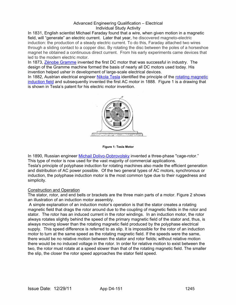
Advanced Engineering Qualification – Electrical Individual Study Activity
Issue Date: 12/29/11 App D4-151 1245
In 1831, English scientist Michael Faraday found that a wire, when given motion in a magnetic field, will “generate” an electric current. Later that year, he discovered magneto-electric induction: the production of a steady electric current. To do this, Faraday attached two wires through a sliding contact to a copper disc. By rotating the disc between the poles of a horseshoe magnet he obtained a continuous direct current. From his early experiments came devices that led to the modern electric motor. In 1873, Zénobe Gramme invented the first DC motor that was successful in industry. The design of the Gramme machine formed the basis of nearly all DC motors used today. His invention helped usher in development of large-scale electrical devices. In 1882, Austrian electrical engineer Nikola Tesla identified the principle of the rotating magnetic induction field and subsequently invented the first AC motor in 1888. Figure 1 is a drawing that is shown in Tesla’s patent for his electric motor invention.
Figure 1: Tesla Motor
In 1890, Russian engineer Michail Dolivo-Dobrovolsky invented a three-phase "cage-rotor.” This type of motor is now used for the vast majority of commercial applications. Tesla's principle of polyphase induction for rotating machines also made the efficient generation and distribution of AC power possible. Of the two general types of AC motors, synchronous or induction, the polyphase induction motor is the most common type due to their ruggedness and simplicity. Construction and Operation The stator, rotor, and end bells or brackets are the three main parts of a motor. Figure 2 shows an illustration of an induction motor assembly. A simple explanation of an induction motor’s operation is that the stator creates a rotating magnetic field that drags the rotor around due to the coupling of magnetic fields in the rotor and stator. The rotor has an induced current in the rotor windings. In an induction motor, the rotor always rotates slightly behind the speed of the primary magnetic field of the stator and, thus, is always moving slower than the rotating magnetic field produced by the polyphase electrical supply. This speed difference is referred to as slip. It is impossible for the rotor of an induction motor to turn at the same speed as the rotating magnetic field. If the speeds were the same, there would be no relative motion between the stator and rotor fields; without relative motion there would be no induced voltage in the rotor. In order for relative motion to exist between the two, the rotor must rotate at a speed slower than that of the rotating magnetic field. The smaller the slip, the closer the rotor speed approaches the stator field speed.
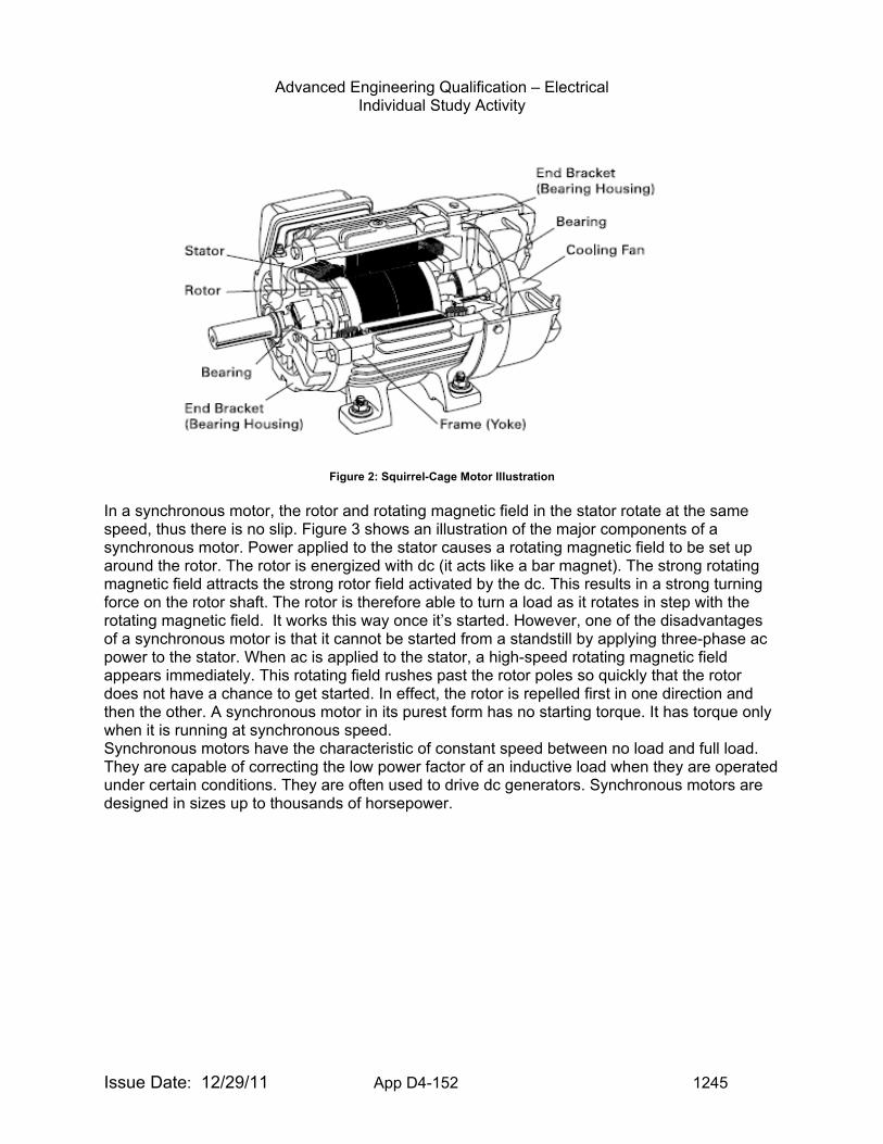
Advanced Engineering Qualification – Electrical Individual Study Activity
Issue Date: 12/29/11 App D4-152 1245
Figure 2: Squirrel-Cage Motor Illustration
In a synchronous motor, the rotor and rotating magnetic field in the stator rotate at the same speed, thus there is no slip. Figure 3 shows an illustration of the major components of a synchronous motor. Power applied to the stator causes a rotating magnetic field to be set up around the rotor. The rotor is energized with dc (it acts like a bar magnet). The strong rotating magnetic field attracts the strong rotor field activated by the dc. This results in a strong turning force on the rotor shaft. The rotor is therefore able to turn a load as it rotates in step with the rotating magnetic field. It works this way once it’s started. However, one of the disadvantages of a synchronous motor is that it cannot be started from a standstill by applying three-phase ac power to the stator. When ac is applied to the stator, a high-speed rotating magnetic field appears immediately. This rotating field rushes past the rotor poles so quickly that the rotor does not have a chance to get started. In effect, the rotor is repelled first in one direction and then the other. A synchronous motor in its purest form has no starting torque. It has torque only when it is running at synchronous speed. Synchronous motors have the characteristic of constant speed between no load and full load. They are capable of correcting the low power factor of an inductive load when they are operated under certain conditions. They are often used to drive dc generators. Synchronous motors are designed in sizes up to thousands of horsepower.
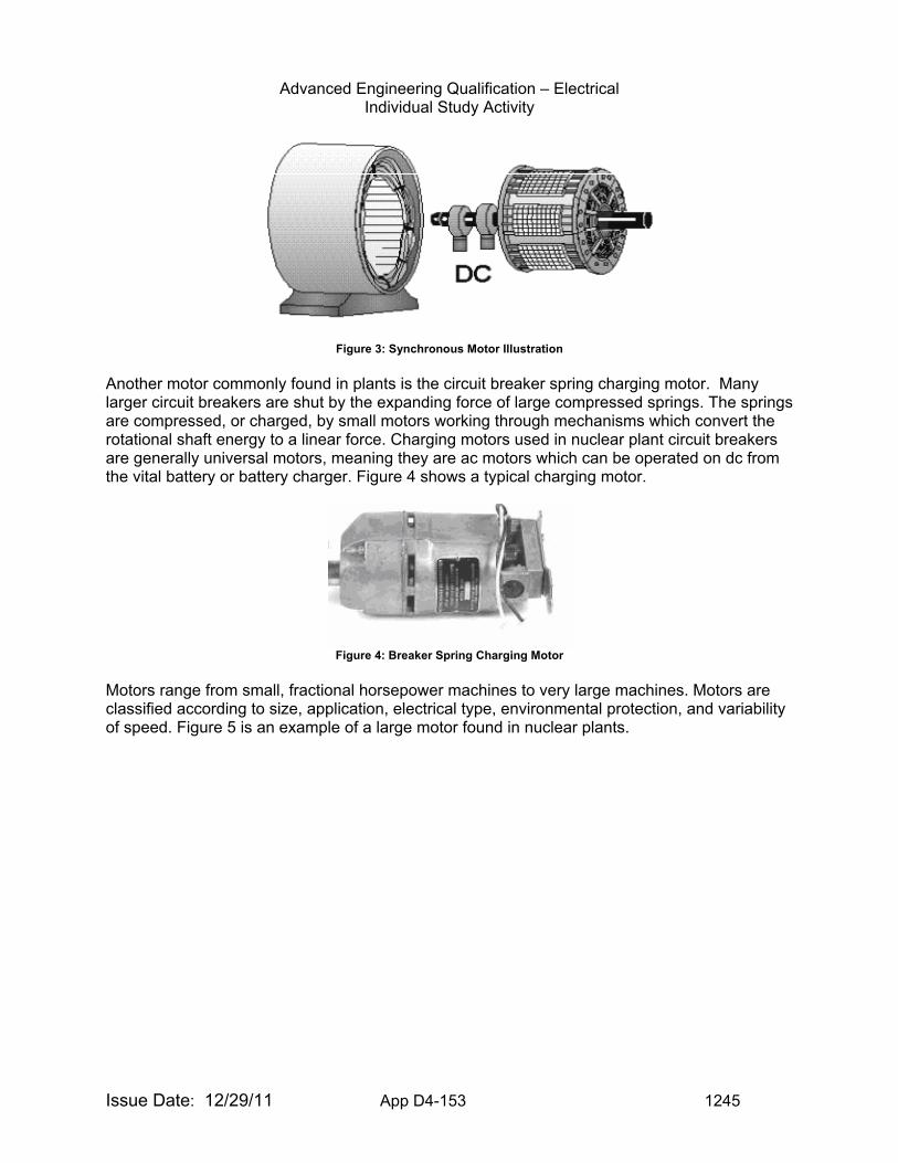
Advanced Engineering Qualification – Electrical Individual Study Activity
Issue Date: 12/29/11 App D4-153 1245
Figure 3: Synchronous Motor Illustration
Another motor commonly found in plants is the circuit breaker spring charging motor. Many larger circuit breakers are shut by the expanding force of large compressed springs. The springs are compressed, or charged, by small motors working through mechanisms which convert the rotational shaft energy to a linear force. Charging motors used in nuclear plant circuit breakers are generally universal motors, meaning they are ac motors which can be operated on dc from the vital battery or battery charger. Figure 4 shows a typical charging motor.
Figure 4: Breaker Spring Charging Motor
Motors range from small, fractional horsepower machines to very large machines. Motors are classified according to size, application, electrical type, environmental protection, and variability of speed. Figure 5 is an example of a large motor found in nuclear plants.
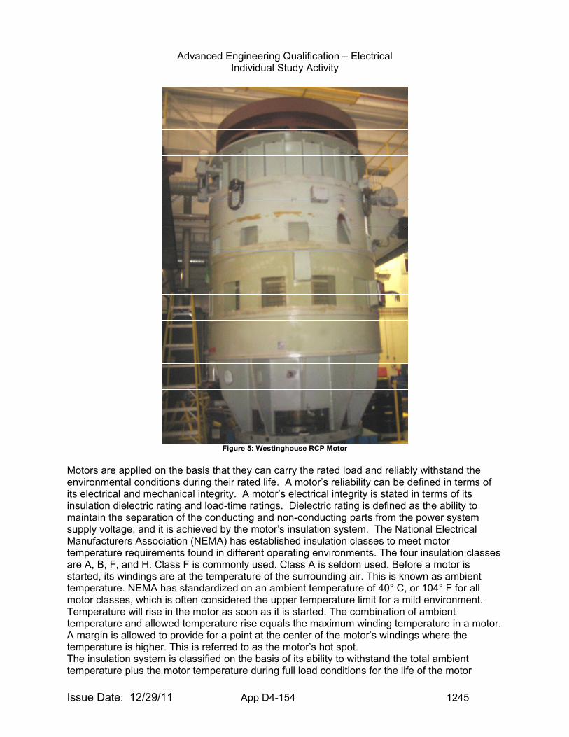
Advanced Engineering Qualification – Electrical Individual Study Activity
Issue Date: 12/29/11 App D4-154 1245
Figure 5: Westinghouse RCP Motor
Motors are applied on the basis that they can carry the rated load and reliably withstand the environmental conditions during their rated life. A motor’s reliability can be defined in terms of its electrical and mechanical integrity. A motor’s electrical integrity is stated in terms of its insulation dielectric rating and load-time ratings. Dielectric rating is defined as the ability to maintain the separation of the conducting and non-conducting parts from the power system supply voltage, and it is achieved by the motor’s insulation system. The National Electrical Manufacturers Association (NEMA) has established insulation classes to meet motor temperature requirements found in different operating environments. The four insulation classes are A, B, F, and H. Class F is commonly used. Class A is seldom used. Before a motor is started, its windings are at the temperature of the surrounding air. This is known as ambient temperature. NEMA has standardized on an ambient temperature of 40° C, or 104° F for all motor classes, which is often considered the upper temperature limit for a mild environment. Temperature will rise in the motor as soon as it is started. The combination of ambient temperature and allowed temperature rise equals the maximum winding temperature in a motor. A margin is allowed to provide for a point at the center of the motor’s windings where the temperature is higher. This is referred to as the motor’s hot spot. The insulation system is classified on the basis of its ability to withstand the total ambient temperature plus the motor temperature during full load conditions for the life of the motor
Advanced Engineering Qualification – Electrical Individual Study Activity
Issue Date: 12/29/11 App D4-155 1245
without deterioration. Operating a motor above the limits of the insulation class reduces the motor’s life expectancy. A 10° C increase in the operating temperature can decrease the life expectancy of a motor as much as 50%. The load-time rating is the ability of a motor to carry a load over a period of time, and is classified as service factor, short-time, and overload duty. The mechanical integrity involves mechanical stresses and the ability to keep moving parts separate from stationary parts. Therefore, the most critical mechanical part of a motor is the bearings, where stationary and rotating parts meet. NEMA standards provide for a ±10 percent tolerance from the nameplate rating for operation of motors, but deviations of voltage have an effect on a motor’s performance. High voltage causes increased torque, starting current, and heat. Low voltage causes reduced starting torque, increased power factor, and increased heating, which reduces the life of the insulation system. Torque is an important value for safety-related loads. A plant’s accident analysis assumes a certain pump flow volume, which is directly related to motor torque. If a centrifugal pump is run at reduced torque, less fluid is pumped, and the motor operates outside of design requirements. The increased power factor causes added stress to the motor’s insulation due to the motor drawing more current than needed for nominal operation. Maintenance Motors must be properly maintained and operated to achieve maximum reliability and efficiency. Motors perform best when they are properly installed, protected, ventilated, and maintained. The justification for the maintenance of motors is to prevent service interruptions resulting from failed equipment, and to ensure operability when needed to mitigate accidents. The maintenance program should include visual inspections of all areas that operating experience has shown to be vulnerable to damage or degradation. The most significant parts that should be visually inspected are the stator and rotor windings, bearings, and electrical connections. Signs of degradation include insulation deterioration, cracking, discoloration, and loose connections.
Advanced Engineering Qualification – Electrical Individual Study Activity
Issue Date: 12/29/11 App D4-156 1245
Examples of Findings for Motors: • 05000341/2004008 Green finding for failure to adequately lubricate and prevent
repetitive failures of the motor bearings for the north main turbine lube oil pump. • 05000237/2004010 Green finding was identified involving several performance issues
which resulted in the initiation of a Unit 2 manual scram, due to failure of the 2A recirculation pump motor. The performance issues included an inadequate process for rewinding the 2A recirculation pump motor when it was installed in 1999, and an inadequate evaluation of the testing of the motor before installation.
• 05000298/2004003 Green finding for failure to perform adequate maintenance on Reactor Recirculation Motor Generator A. Inadequate maintenance on the motor generator field brushes resulted in the loss of field voltage, an unexpected trip of the motor generator, and an unplanned reduction in reactor power.
• 05000271/2006004 Green finding for failure of licensee to effectively incorporate existing industry operating experience into the preventive maintenance (PM) strategy for the reactor building closed cooling water (RBCCW) system pump motor as required by PM program. As a result, conditions that ultimately resulted in the failure of the RBCCW pump motor went unrecognized.
• 05000301/2005013 Green NCV for failure of licensee to perform a technical evaluation for exceptions taken to motor specifications in the refurbishment of safety-related equipment.
Examples of information to request for inspection of motor Issues: For any inspection to be successful, the inspector must request the right information in order to evaluate whether the licensee is correctly interpreting and applying requirements, industry standards, lessons learned and industry best practices. The following examples may be useful in requesting licensee information.
• Maintenance procedures for motors. • Receipt inspection documentation for motors. • History of failures of motors. • Maintenance Rule documentation involving motors.
Items of Interest to Inspectors for Motors: Motors play a vital role in the safe operation of nuclear power plants. Problems may be found in several areas including programmatic, procedural, and maintenance. Each area should be reviewed for potential weaknesses involving motor operation and maintenance. Training associated with Motors: Motor and Generator Maintenance and Testing - AVO Training Institute, Inc. EVALUATION CRITERIA: Upon completion of the tasks in this guide, you will be asked to demonstrate
your understanding of motors by performing the following:
1. Describe the basic principles of motor operation.
2. Describe, in general, the following types of AC motors: a. Induction b. Synchronous c. Series-Wound
Advanced Engineering Qualification – Electrical Individual Study Activity
Issue Date: 12/29/11 App D4-157 1245
3. Describe, in general, the following types of polyphase motors: a. Squirrel-Cage Induction b. Wound-Rotor Induction
4. Describe the following terms as they are related to motors:
a. Stator b. Rotor c. Torque d. Slip e. Power Factor f. Efficiency g. Service Factor h. Insulation Class i. Minimum Voltage
5. Discuss how the maintenance rule, 10 CFR 50.65, relates to motor maintenance.
6. Discuss some of the inspections and testing that licensees should perform on motors.
7. Discuss circuit breaker spring charging motors and their function.
TASKS:
1. Read the references in sufficient detail to perform adequately in accordance with the requirements of the evaluation criteria.
2. Meet with your supervisor, or the person designated to be your resource for this activity, and discuss the answers to the questions listed under the evaluation criteria.
3. Familiarize yourself with the inspection resources listed under the Operational Experience website.
4. Familiarize yourself with the documentation necessary to perform inspections of motors.
DOCUMENTATION: Advanced Engineering Qualification – Electrical Signature Card Item ISA-EE-18
Advanced Engineering Qualification – Electrical Individual Study Activity
Issue Date: 12/29/11 App D4-158 1245
TOPIC: (ISA-EE-19) Motor-Operated Valves (MOV) PURPOSE: The purpose of this guide is to provide the inspector with insight into design
and regulatory issues associated with motor-operated valves. COMPETENCY AREA: INSPECTION LEVEL OF EFFORT: To be determined by Branch Chief or supervisor. REFERENCES: 1. 2.
Motorized Valve Actuators Course Manual (E-112)
http://papaya.nrc.gov/E-112/home.htm
3. IEEE Std 1290 IEEE Guide for Motor Operated Valve (MOV) Motor Application, Protection, Control, and Testing in Nuclear Power Generating Stations
4.
NRC Generic Letter 89-10
Safety-Related Motor-Operated Valve Testing And Surveillance - 10 CFR 50.54(f)
5. NRC Generic Letter 96-05 Periodic Verification of Design-Basis Capability of Safety-Related Motor-Operated Valves
6. Regulatory Guide 1-106 Thermal Overload Protection for Electric Motors on Motor-Operated Valves
Examples of Event Reports to Review for MOVs: 38810 Hatch Motor Operated Valve 2E41F104 failed to indicate OPEN. This is one
of two in-line Primary Containment Isolation Valves (PCIV) that provide vacuum breaker isolation capability for the High Pressure Coolant Injection (HPCI) Steam Turbine Exhaust line.
40389 Surry The AFW system has six motor operated valves (MOVs), two for each SG, which are used to control flow from one of two AFW headers. Three MOVs are powered from "H" emergency bus and three MOVs are powered from "J" emergency bus. The MOVs are maintained normally open. With a loss of emergency power to either train of AFW MOVs, the control room operators are not able to close the three MOVs from the de-energized emergency bus without manual action inside containment. A review of the plant safety analysis design basis indicates that with this AFW configuration, isolation of AFW to a ruptured SG would not be possible within the time frame specified in the analysis.
43436 Limerick During performance of the quarterly HPCI valve stroke test the HV-55-2F006, HPCI pump discharge isolation valve to Core Spray failed to open within the maximum allowed time. The HV-55-2F006 valve is a motor operated valve and the maximum allowed opening time is 17.25 seconds. The valve was given an open signal via the hand switch as required by the test but did not initially respond. Several minutes later the valve went full open. HPCI was declared inoperable at 0315 on 6/21/2007.
Advanced Engineering Qualification – Electrical Individual Study Activity
Issue Date: 12/29/11 App D4-159 1245
42929 Clinton At 0142 on October 24, 2006, while aligning the High Pressure Core Spray system for surveillance testing of the Reactor Core Isolation Cooling System Storage Tank Level instrumentation, 1E22-F015, the Suppression Pool suction valve for the High Pressure Core Spray pump, failed to stroke fully open. High Pressure Core Spray was declared inoperable as a result. This event is considered a loss of a single train system needed to mitigate the consequences of an accident. The High Pressure Core Spray system was restored to an operable condition at 0506 on October 24, 2006 after the suction valve was successfully stroked open and the HPCS suction source was aligned to the Suppression Pool in accordance with Technical Specification Limiting Condition for Operation 3.5.1.
Examples of Findings for MOVs: Crystal River - A Green finding was identified for failure to conduct an extent of condition evaluation when three motor operated valves (MOVs) which were thought to not be susceptible to incorrect pinion gear installation were found with their pinion gears installed backwards. Callaway - Two licensee calculations contained incomplete and incorrect methods of evaluating degraded voltage conditions. Calculation ZZ-214, "Motor Operated Valve Feeder Cable Voltage Drops," Addenda 1, Revision 2, for determining minimum voltage to motor-operated valves, did not consider the effect of motor starting currents in circuit elements upstream of the motor control centers. Monticello - The NRC identified a Green NCV of 10 CFR Part 50, Appendix B, Criterion V, for the failure to identify and correct a Condition Adverse to Quality (CAQ). Specifically, the licensee failed to capture in the CAP a concern with the potential corrosion of magnesium motor rotor fan blades associated with safety-related motor operated valves (MOVs). The MOVs were associated with the reactor recirculation and residual heat removal (specifically the low pressure core injection mode) systems. McGuire - The NRC identified a finding of very low safety significance involving a NCV of 10 CFR 50, Appendix B, Criterion III, "Design Control," for the licensee's failure to assure that the applicable design bases were correctly translated into the in-service test (IST) acceptance criteria for safety-related motor operated valves (MOVs). Specifically, the licensee's testing did not account for test inaccuracies associated with limit switch actuation or minimum EDG frequency into IST stroke time testing. River Bend Station - The team identified a finding of very low safety significance involving a noncited violation of 10 CFR Part 50, Appendix B, Criterion III, Design Control, with examples. Example 1: Non-conservative inputs and assumptions used without adequate technical justification to evaluate the minimum terminal voltage and actuator output torque for safety-related motor operated valves. Example 2: Failure to perform a conservative analysis to ensure that Technical Specification Setpoints were adequate. Example 3: Non-conservative inputs and methodologies used in calculating control circuit voltages to safety-related 480V motor operated valves motor-operated valve and motors that would be required to operate for mitigation of design bases events. Example 4: Failure to evaluate E12-MOV-F042A, residual heat removal injection valve, and E12-MOV-F064A, residual heat removal minimum flow valve, to verify adequate voltage would be available to operate the associated 120VAC control circuit devices.
Advanced Engineering Qualification – Electrical Individual Study Activity
Issue Date: 12/29/11 App D4-160 1245
Farley – The inspectors identified a Yellow finding having substantial safety significance of 10 CFR 50, Appendix B, Criterion XVI, Corrective Action, for the licensee’s failure to promptly identify and correct a condition adverse to quality which resulted in a Unit 2 residual heat removal containment sump suction valve failing to stroke full open during testing on April 29, 2006, and again on January 5, 2007. Examples of Information to Request for Inspection of MOVs:
• Request the licensee’s response to applicable generic communications related to MOV’s, (i.e. GL89-10)
• Request copies of surveillance and maintenance procedures for safety-related MOV’s. • Request one-line and/or three-line diagrams of MOV circuits • Request vendor manuals for the associated MOV’s
Items of Interest to Inspectors for MOVs: Many examples exist of items of interest concerning motor operated valve actuators, including magnesium rotor issues, incorrect thermal overload relay settings, and failure to implement requirements of generic communications associated with MOV’s. Training associated with MOVs: Motorized Valve Actuators Course (E-112) Technical Training Center EVALUATION CRITERIA: Upon completion of the tasks in this guide, you will be asked to demonstrate
your understanding of Motor-Operated Valves by performing the following:
1. Describe the types of motor-operated valve actuators with emphasis on the most common types used in nuclear power plants.
2. Explain the operation of the various valve and actuator designs used in typical motor-operated valve service, including operation at design basis.
3. Explain the application of motor actuator types, including the principals and techniques used in selecting the appropriate actuator for a given use.
4. Explain the operation of standard motorized actuator control circuits. 5. Understand the methods for measuring the operational performance of MOVs and
discuss the expected results. 6. Discuss the regulatory issues associated with MOV sizing and performance, and discuss
the history of MOV problems and failures. 7. Discuss the impact of Generic Letter 89-10, “Safety-Related Motor-Operated Valve
Testing and Surveillance,” on the nuclear industry.
TASKS: 1. Read the references in sufficient detail to perform adequately in accordance with the
requirements of the evaluation criteria. 2. Meet with your supervisor, or the person designated to be your resource for this activity,
and discuss the answers to the questions listed under the evaluation criteria. 3. Familiarize yourself with the inspection resources listed under the Operational
Experience website. 4. Familiarize yourself with the documentation necessary to perform electrical inspections
of Motor-Operated Valves. DOCUMENTATION: Advanced Engineering Qualification – Electrical Signature Card Item ISA-
EE-19
Advanced Engineering Qualification – Electrical Individual Study Activity
Issue Date: 12/29/11 App D4-161 1245
TOPIC: (ISA-EE-20) Emergency Lighting PURPOSE: The purpose of this guide is to provide the inspector with the background
knowledge necessary to inspect emergency lighting units. This activity occurs most often during Fire Protection inspections.
COMPETENCY AREA: INSPECTION LEVEL OF EFFORT: As determined by Branch Chief or supervisor REFERENCES: 1. 10 CFR 50, Appendix R, Section III.J, “Emergency Lighting” 2. License Documents 3. FSAR Section 9.5 for selected plant 4. License Condition and applicable SER/SSER for selected plant 5. Generic Communications
• Information Notice 90-69, Adequacy of Emergency and Essential Lighting • Information Notice 95-36, Potential Problems with Post-Fire Emergency Lighting • Regulatory Guide 1.189, Fire Protection for Nuclear Power Plants, Emergency
Lighting 6. 10 CFR Part 50.65, Requirements for monitoring the effectiveness of maintenance at
nuclear power plants
Examples of Event Reports to Review for Emergency Lighting None Examples of Findings for Emergency Lighting Pilgrim - Entergy failed to implement effective maintenance on the emergency lighting system in a manner necessary to prevent repeated functional failures from causes which were within the licensee's capability to foresee and prevent. As a result of failures predominately due to low battery electrolyte levels and the improper adjustment of the battery charger output voltage, the emergency lighting system experienced 20 functional failures in a 36-month period and failed to meet the reliability performance criteria in four of the last five years. Farley – The licensee failed to fully implement test control requirements incorporated in approved plant procedures associated with the periodic testing of emergency lighting units. As a consequence, condition reports (CRs) were not initiated as required, when battery conductance measurements did not meet acceptance criteria. Indian Point Unit 3 - A non-cited violation (NCV) of 10 CFR 50.65, Requirements for Monitoring the Effectiveness of Maintenance at Nuclear Power Plants, was identified in that Entergy did not monitor the performance or condition of the emergency lighting system against licensee-established goals, in a manner sufficient to provide reasonable assurance that the system was capable of fulfilling its intended function. Specifically, in January 2007, Entergy returned the emergency lighting system to a 10 CFR 50.65(a)(2) status without taking appropriate corrective action when established goals were not met in accordance with its action plan. Catawba - A non-cited violation (NCV) of Units 1 and 2 Operating License Condition 2.C.(5) was identified for the failure to follow the emergency battery lighting maintenance and testing procedure IP/0/B/3540/002, Emergency Battery Lighting Periodic Maintenance and Testing, during replacement of failed batteries. The licensee stated that the batteries were routinely
Advanced Engineering Qualification – Electrical Individual Study Activity
Issue Date: 12/29/11 App D4-162 1245
tested prior to installation while in the maintenance shop; however, this bench test was neither required by the periodic maintenance and testing procedure nor documented in any test record. Peach Bottom - A non-cited violation of Condition 2.C.4 of the operating licenses for both Units 2 and 3 was identified because Exelon did not adequately maintain emergency lighting units with at least an 8-hour battery power supply in three areas needed for operation of safe shutdown equipment. The Peach Bottom Fire Protection Plan (FPP) required emergency lighting for safe shutdown and emergency response in the event of fire. Susquehanna - The inspectors identified a non-cited violation of 10 CFR 50.65 (a)(2), the Maintenance Rule, because PPL did not demonstrate the effectiveness of preventative maintenance for the emergency lighting systems and did not place the systems in a 50.65(a)(1) category and monitor against established goals. As a result, a progressive degradation of the 125 VDC emergency lighting systems occurred that caused the lighting systems to not be capable of performing their intended function. Susquehanna – A non-cited violation of Technical Specification 5.4.1, with two examples, was identified because PPL did not implement their written procedures for the fire protection program and the control of plant equipment. The removal of the Unit 1 emergency lighting system was not adequately communicated to the control room (failure to control plant equipment). As a result, during replacement of the Unit 1 emergency lighting system 125 VDC battery, PPL did not perform required compensatory actions to provide portable sealed beam hand lights throughout the plant. Examples of Information to Request for Inspection of Emergency Lighting:
• Maintenance Rule Program Information for Emergency Lighting System(s) • Copies of/or Access to Emergency Lighting Vendor Manual • Condition Report History for Emergency Lighting Issues
Training associated with Emergency Lighting: None EVALUATION CRITERIA: Upon completion of the tasks in this guide, you will be asked to demonstrate
your understanding of emergency lighting by performing the following:
1. State the regulatory requirement for Emergency Lighting 2. Be able to discuss the licensing basis requirements for Emergency Lighting for a
selected plant 3. Be able to discuss the potential problems associated with Emergency Lights as
described in the listed generic communications
TASKS: 1. Read the references in sufficient detail to perform adequately in accordance with the
requirements of the evaluation criteria. 2. Meet with your supervisor, or the person designated to be your resource for this activity,
and discuss the answers to the questions listed under the evaluation criteria. 3. Familiarize yourself with the inspection resources listed under the Operational
Experience website. 4. Familiarize yourself with the documentation necessary to perform inspections of
Emergency Lighting. DOCUMENTATION: Advanced Engineering Qualification – Electrical Signature Card Item ISA-
EE-21
Advanced Engineering Qualification – Electrical Individual Study Activity
Issue Date: 12/29/11 App D4-163 1245
TOPIC: (ISA-EE-21) Alternate AC Power/Station Blackout PURPOSE: Based on the risk significance of a station blackout event, the NRC amended
its regulations with the addition of 10 CFR 50.63, “Loss of all alternating current power.” This rule added requirements intended to ensure that all plants could maintain core cooling and containment isolation capability when both offsite and onsite power sources were not available to power the AC safety buses for a limited duration.
The purpose of this guide is to provide the inspector with advanced knowledge useful in the inspection of station blackout/alternate AC sources issues.
COMPETENCY AREA: INSPECTION LEVEL OF EFFORT: As determined by Branch Chief or supervisor REFERENCES: 1. 10 CFR 50.63 Loss of All Alternating Current Power (June 1988) 2. Regulatory Guide 1.155 Station Blackout (August 1988) 3. NUMARC-8700 Guidelines and Technical Bases for NUMARC Initiatives
Addressing Station Blackout at Light Water Reactors (November 1987)
4. NSAC-108 Reliability of Emergency Diesel Generators at U.S. Nuclear Power Plants (September 1986)
5. NUREG-6890 Reevaluation of Station Blackout Risk at Nuclear Power Plants
Examples of Event Reports to Review for Station Blackout:
• Oyster Creek – LER 1994-019 SBO Power Source Unavailable Due To Inadequate Design Of Modification
• Fort Calhoun – LER 1997-015 Unanalyzed Condition for the Station Batteries • Cooper – LER 1995-013 Plant Procedural Requirements Inconsistent with Station
Blackout Assumptions • Zion 1 & 2 – LER 1994-001 Actuation of Unit 2 Station Blackout Loads During
Restoration of Buses 147/247 to Offsite Power • St. Lucie – LER 1998-007 Inadequate Procedure May Result in Station Blackout
Recovery Complications • South Texas 1 & 2 – LER 1994-013 Failure to Fully Meet the Requirements of the
Station Blackout Rule • Susquehanna 1 - LER 1999-027 Incorrect Assumption Made for 250 VDC Battery
Load Profiles
Advanced Engineering Qualification – Electrical Individual Study Activity
Issue Date: 12/29/11 App D4-164 1245
Examples of Findings for Station Blackout: Palo Verde - Ineffective Demonstration of Conformance to Design for the Alternate AC Power Sources. The finding involved the implementation of Regulatory Guide 1.155, Station Blackout, Appendix A, for the demonstration of the station blackout generator design and system readiness requirements. Specifically, established preventive maintenance tasks did not demonstrate that the coping requirements for the station blackout generator would be met for the approved increase from the 4-hour to 16-hour coping duration. Seabrook - Inadequate Operability Determination of the TDEFW Pump Relative to Station Blackout. The finding involved license's failure to perform an adequate operability determination for a degraded outboard thrust bearing on the turbine-driven emergency feedwater (TDEFW) pump. Specifically, the licensee did not identify how this bearing would have affected the TDEFW pump's ability to provide core cooling during a station blackout. Fermi - Inadequate implementation of the modification process prevented a gas turbine from starting during a loss of offsite power. The finding involved an improper modification process used to install an inverter on a gas turbine. An inverter low voltage trip set point was set too high and prevented the gas turbine from starting on demand during a station blackout. Kewaunee - Lack of operator Procedure Guidance for Actions Following Station Blackout. The finding involved a non-cited violation of 10 CFR 50.63, "Loss of All Alternating Current Power," for a failure to maintain procedural steps that minimized the likelihood and duration of a station blackout event. Callaway - Safety Related 125 Vdc Station Battery Inadequate Battery Sizing Calculation. The finding involved the failure to verify the adequacy of design and for failure to correctly translate the 125 Vdc system design basis into instructions, procedures, and drawings. The failure to include all required loads prevented the licensee from developing a battery duty cycle profile that conforms to the guidance of IEEE 485-1983 and correctly simulates the battery loads following a design basis or station blackout event. Vermont Yankee - Inadequate Procedure for Station Blackout Load Shedding. The finding involved a non-cited violation of 10 CFR 50.63, Loss of all Alternating Current Power in that the licensee did not ensure that adequate battery capacity would be available during a station blackout. Specifically, unrecognized delays in performing a credited manual direct current (DC) load shedding operator action, as well as an incorrectly translated minimum battery voltage referenced in the station blackout procedure, could have resulted in the station battery capacity being insufficient during an station blackout event. LaSalle - Lack of Station Blackout Analysis for RCIC. The finding involved a non-cited violation of 10 CFR 50.63, Loss of All Alternating Current Power. Specifically, the licensee did not have an appropriate analysis to determine the capability of coping with a station blackout. There was no analysis that verified the proper operation of the reactor core isolation cooling (RCIC) turbine at the elevated suppression pool temperatures encountered during a station blackout event. Browns Ferry - Lack of Assured Cooling Water for Emergency Diesel Generators During SBO Conditions. The finding involved a non-cited violation of 10 CFR 50, Appendix B, Criterion III, Design Control, which affected Units 2 and 3. The licensee calculations and procedures did not adequately implement the plant licensing basis for station blackout, in that, they did not ensure
Advanced Engineering Qualification – Electrical Individual Study Activity
Issue Date: 12/29/11 App D4-165 1245
the operating emergency diesel generators would have an adequate cooling water supply during a station blackout with certain plant equipment configurations. Point Beach – Lack of a 4 Hour SBO Coping Duration Heat-Up Calculation for the AFP Rooms. The finding involved a violation of 10 CFR 50.63, Loss of all Alternating Current Power. Specifically, the licensee never performed a calculation that evaluated the effects of loss of ventilation on the auxiliary feedwater pump (AFP) room during a station blackout. The AFP rooms, which each house a turbine driven AFP had not been evaluated for the heatup that would occur during the station blackout 4 hour coping duration. Peach Bottom - Failure to Recognize the Loss of Function of the Station Blackout Transformer Tap Changer and the Impact on the SBO Power Supply to the Emergency Buses. The finding involved a non-cited violation of 10 CFR 50.63, Loss of All Alternating Current Power, in that the station blackout coping analysis for the configuration that existed from September 14 until December 1, 2004, was inadequate. Lack of design documentation and administrative controls resulted in inadequate configuration control of the station blackout system that would have de-energized the power feed to its control power circuit following a station blackout event. Examples of Information to Request for Inspection of Station Blackout:
• Station Blackout Analysis and Supporting Calculations • Operations Procedures for Loss-of-All AC Power • Maintenance and Testing Records for the Alternate AC Power (AAC) Source
Items of Interest to Inspectors for Station Blackout:
• “Final Report on The August 14, 2003 Blackout in the United States and Canada: Causes and Recommendations,” U.S.-Canada Power System Outage Task Force, April 5, 2004 (http://www.nerc.com/~filez/blackout.html)
Training associated with Station Blackout: None
EVALUATION CRITERIA: Upon completion of the tasks in this guide, you will be asked to demonstrate
your understanding of the risk implications of a SBO and the requirements and strategies for coping with and recovering from these events.
1. Define what constitutes a station blackout condition. 2. Discuss the factors which must be considered when determining the necessary coping
period for a specific plant.
a. Redundancy of onsite AC power sources b. Reliability of onsite emergency AC sources c. Expected frequency of loss of offsite power d. Expected time necessary to restore offsite power e. Adverse Weather
3. Discuss the difference in analysis requirements for plants that choose to utilize an
alternate AC (AAC) power source to meet the SBO rule and the types of AAC sources that may be used.
Advanced Engineering Qualification – Electrical Individual Study Activity
Issue Date: 12/29/11 App D4-166 1245
a. Non-safety diesel generator b. Safety related EDG cross-connected from another unit c. Gas turbines d. Hydro-electric generating units
4. Discuss the design criteria specific to the alternate AC power source.
a. Normal alignment b. Independence from onsite emergency sources c. Availability time and associated test requirements d. Capacity e. Maintenance, testing and reliability requirements
5. Discuss what procedures a typical plant would be expected to have and some of the
more significant operator actions that would be included.
a. RCP seal cooling for PWRs (Loss/Restoration) b. Steam driven pump operations (AFW/RCIC/HPCI) c. Minimize loss of reactor coolant inventory d. DC load shedding e. Room cooling/temporary ventilation f. Start/align alternate AC source
6. Discuss quality assurance requirements for non-safety related SBO equipment.
TASKS:
1. Read the references in sufficient detail to perform adequately in accordance with the requirements of the evaluation criteria.
2. Review a station blackout analysis and associated NRC safety evaluation report for a PWR and a BWR. If possible one should be with the use of an AAC and one without (full coping analysis).
3. Review the “Loss of All AC Power” procedures for the plants chosen for Item (2) above. 4. Meet with your supervisor, or the person designated to be your resource for this activity,
and discuss the areas listed under the evaluation criteria. 5. Familiarize yourself with the inspection resources listed under the Operational
Experience website. DOCUMENTATION: Advanced Engineering Qualification - Electrical Signature Card Item ISA-
EE-21
Advanced Engineering Qualification – Electrical Individual Study Activity
Issue Date: 12/29/11 App D4-167 1245
TOPIC: (ISA-EE-22) Emergency Diesel Generator and Support Systems PURPOSE: The purpose of this guide is to provide the inspector with general knowledge
of the major means of supplying onsite emergency (standby) electrical power for nuclear power plants by way of emergency diesel generator sets (EDGs). This guide will also provide a summary overview of the EDG and associated support systems and components and their general interface with site facilities.
It is important to establish that for the EDG to be capable of performing its
design basis function, both on-skid and off-skid support systems and components must also meet their design basis functional requirements.
COMPETENCY AREA: INSPECTION LEVEL OF EFFORT: To be determined by Branch Chief or supervisor REFERENCES: 1. IEEE Std 308 IEEE Standard Criteria for Class 1E Power Systems for Nuclear Power
Generating Stations 2. IEEE Std 323 IEEE Standard for Qualifying Class 1E Equipment for Nuclear Power
Generating Stations 3. IEEE Std 344 Recommended Practice for Seismic Qualification of Class 1E
Equipment for Nuclear Power Generating Stations 4. IEEE Std 387 IEEE Standard Criteria for Diesel Generator Units Applied as Standby
Power Supplies for Nuclear Power Generating Stations 5. IEEE Std 603 Standard Criteria for Safety Systems for Nuclear Power Generating
Stations 6. IEEE Std 741 Standard Criteria for the Protection of Class 1E Power Systems and
Equipment in Nuclear Power Generating Stations 7. IEEE Std 1205 Guide for Assessing, Monitoring, and Mitigating Aging Effects on Class
1E Equipment Used in Nuclear Power Generating Stations 8. ANSI/ANS-
59.51 Fuel Oil Systems for Safety Related Emergency Diesel Generators
9. SRP 9.5.4 Emergency Diesel Engine Fuel Oil Storage and Transfer System 10. SRP 9.5.5 Emergency Diesel Engine Cooling Water System 11. SRP 9.5.6 Emergency Diesel Engine Starting System 12. SRP 9.5.7 Emergency Diesel Engine Lubrication System 13. SRP 9.5.8 Emergency Diesel Engine Combustion Air Intake and Exhaust System 14. RG 1.9 Selection, Design, Qualification and Testing of Emergency Diesel-
Generator Units Used as Class 1E Onsite Electric Power Systems at Nuclear Power Plants
15. BL 79-23 Potential Failure of Emergency Diesel Generator Field Exciter Transformer
16. GL 79-17 Reliability of Onsite Diesel Generators at Light Water Reactors 17. GL 77-07 Reliability Of Standby Diesel Generator Units
Advanced Engineering Qualification – Electrical Individual Study Activity
Issue Date: 12/29/11 App D4-168 1245
Examples of Event Reports to Review for Emergency Diesel Generators: LER 06-004-01 for Palo Verde, Unit 3 LER 00-002-00, Cooper Nuclear Station LER 04-002-00 Fort Calhoun Station LER 06-001-01 for Calvert Cliffs, Units, 1 & 2
Examples of Findings for EDGs: • A self-revealing noncited violation of 10 CFR Part 50, Appendix B, Criterion III, Design
Control, was identified associated with small flash fires that occurred on the Unit 2 Emergency Diesel Generator 2K-4A on April 15, 2007. Specifically, the licensee failed to verify that the outer protective cover for insulation used on the exhaust manifold was rated for expected temperatures.
• A self-revealing noncited violation of Technical Specification 5.4.1.a was identified for the failure of maintenance personnel to follow procedures. Specifically, on April 2, 2006, maintenance personnel failed to follow Procedure 73ST-9DG02, "Class 1E Diesel Generator and Integrated Safeguards Test, Train B," by installing a jumper on the incorrect relay while testing the overcurrent trip. This resulted in an emergency diesel generator trip and de-energization of safety-related Bus PBB-S04.
• A self-revealing, noncited violation of 10 CFR Part 50, Appendix B, Criterion XVI, was identified regarding inadequate corrective actions for repetitive failures of a lube oil instrument line on Emergency Diesel Generator 1. Between 1989 and 2004, the configuration of this instrument was susceptible to high-cycle fatigue failures and experienced three such failures. Corrective actions only replaced the failed material; the line remained in a configuration susceptible to further failures.
• A violation of 10 CFR Part 50, Appendix B, Criterion XVI, was identified for the failure to ensure that conditions adverse to quality, such as failures, malfunctions, etc., are promptly identified and corrected. Specifically, on July 21, 2004, during surveillance testing of Emergency Diesel Generator 2, the licensee failed to promptly identify and correct a failure of Fuse 2FU in the emergency diesel generator excitation circuit. The failure to identify and correct this condition resulted in Emergency Diesel Generator 2 being inoperable from July 21 to August 19, 2004, a period of 29 days, exceeding Technical Specification 2.7 allowed outage time of 7 days during any month when the reactor coolant system temperature was greater than 300°F.
Examples of Information to Request for Inspection of EDG Issues: For any inspection to be successful, the inspector must request the right information in order to evaluate whether the licensee is correctly interpreting and applying requirements, industry standards, lessons learned and industry best practices. The following examples may be useful in requesting licensee information.
• Maintenance procedures for EDG. • Maintenance procedures involving Lube Oil System and Relay Checks. • Receipt inspection documentation for EDG Components. • History of failures on the site’s EDGs. • Maintenance Rule documentation involving EDG Components.
Advanced Engineering Qualification – Electrical Individual Study Activity
Issue Date: 12/29/11 App D4-169 1245
Emergency Diesel Generator Items of Interest to Inspectors: Emergency Diesel Generators play a vital role in the safe operation of nuclear power plants. Problems may be found in several areas including programmatic, procedural, and maintenance. Each area should be reviewed for potential weaknesses involving EDG operation, surveillance, and maintenance. Training associated with Emergency Diesel Generators: E-111 – Emergency Diesel Generator Course E-800 – EDG Governor Conversion Training Courses offered by: Fairbanks Morse - http://www.fairbanksmorse.com/training.php Electro-Motive Diesel, Inc. - http://www.emdiesels.com/emdweb/services/train_index.jsp EVALUATION CRITERIA: Upon completion of the tasks in this guide, you will be asked to demonstrate
your understanding of emergency diesel generators, their operation, maintenance requirements, and how aging affects their performance by performing the following:
1. Define the purpose of the Emergency Diesel Generator. Contrast this definition with that for the Main Turbine Generator.
2. Explain the purpose of the following devices as they relate to EDG:
a. Idle Speed Relay b. Flywheel and coupling (if applicable) c. Combustion air system d. starting system e. Starting energy system f. Fuel oil system g. Lubricating oil system h. Cooling system i. Exhaust system j. Governor system k. Excitation and voltage regulation systems l. Local control, protection, and surveillance systems m. AC and DC distribution systems
3. Describe the mechanical and electrical capabilities that EDG’s shall have in order to
meet design requirements. Include such items as: a. Design condition b. Starting and loading c. Light-load or no-load operation d. Design load e. Quality of power
4. Describe the following EDG design features:
a. Vibration b. Torsional vibration c. Overspeed d. Governor operation e. Voltage regulator operation
Advanced Engineering Qualification – Electrical Individual Study Activity
Issue Date: 12/29/11 App D4-170 1245
f. Control modes and points g. Surveillance systems and modes h. Surveillance instrumentation i. Protection
5. Each engine shall be tested, utilizing either a water brake dynamometer or a generator
to provide accurate means to control power absorption. Explain why the following tests shall be performed: a. Break-in test b. Performance test
i. Test runs ii. Data logging iii. Controls-alarm and shutdown iv. Inspection
6. Describe each of the following EDG qualification requirements: Initial type tests
a. Aging b. Seismic qualification requirements c. Ongoing surveillance d. Modification e. Documentation
7. Get familiar with the different site testing that is performed to show that the EDG’s are
operable. 8. Discuss how the maintenance rule, 10 CFR 50.65, relates to EDG maintenance. 9. Get familiar with the regulatory requirements that each licensee has that require them to
have EDG’s installed at their plants.
10. Explain the difference between an EDG and a Station Blackout Generator. TASKS:
1. Read the references in sufficient detail to perform adequately in accordance with the requirements of the evaluation criteria.
2. Meet with your supervisor, or the person designated to be your resource for this activity, and discuss the answers to the questions listed under the evaluation criteria.
3. Familiarize yourself with the inspection resources listed under the Operational Experience website.
4. Familiarize yourself with the documentation necessary to perform inspections of EDGs and the related systems.
DOCUMENTATION: Advanced Engineering Qualification – Electrical Signature Card Item ISA-
EE-22
Advanced Engineering Qualification – Electrical Individual Study Activity
Issue Date: 12/29/11 App D4-171 1245
TOPIC: (ISA-EE-23) Instrumentation and Control PURPOSE: The purpose of this activity is to provide the inspector with general
knowledge of the design qualification of instrumentation and control systems and functional requirements when implementing a digital protection system. This guide will also provide a summary overview of the standards that address the use of analog and digital instrumentation and control in nuclear power plants.
COMPETENCY AREA: INSPECTION LEVEL OF EFFORT: As determined by Branch Chief or supervisor REFERENCES: 1. 10 CFR 50 Appendix A, General Design Criteria (GDC) 1, 2, 4, 13, 19, 20, 21, 22, 23,
24, 29, and 64 2. IEEE Std 603-1991, "IEEE Standard Criteria for Safety Systems for Nuclear Power
Generating Stations" 3. IEEE Std 279-1971, "IEEE Standard Criteria for Protection Systems for Nuclear Power
Generating Stations" 4. R.G. 1.28, "Quality Assurance Program Requirements (Design and Construction)" 5. NUREG-0800, Chapter 7, "Instrumentation and Control" 6. 10 CFR 50.59, "Changes, tests, and experiments" 7. Generic Letter 95-02, "NUMARC/EPRI Report TR-102348, Guideline on Licensing
Digital Upgrades" 8. NUMARC/EPRI Report TR-102348, "Guideline on Licensing Digital Upgrades" 9. RIS 2002-22, "Use of NUMARC/EPRI TR-102348 in Determining the Acceptability of
Performing Analog to Digital Replacements Under 10 CFR 50.59" 10. NUREG/BR-0227 "Guidance for Professional Development of NRC Staff in Digital
Instrumentation and Control, By Steven Arndt, September, 1996 11. R.G. 1.152, "Criteria for Digital Computers in Safety Systems of Nuclear Power Plants" 12. R.G. 1.168, "Verification, Validation Reviews and Audits" 13. R.G. 1.169, "Software Configuration Management" 14. R.G. 1.172, "Software Requirements Specification" 15. R.G. 1.170, "Software Test Documentation" 16. R.G. 1.173, "Software Life Cycle" 17. R.G. 1.171, "Software Unite Test" 18. IEEE Std 7-4.3.2, "IEEE Standard for Digital Computers in Safety Systems of Nuclear
Generating Stations" 19. EPRI TR-106439, "Guideline on Evaluation and Acceptance of Commercial Grade
Digital Equipment for Nuclear Safety Applications"
Advanced Engineering Qualification – Electrical Individual Study Activity
Issue Date: 12/29/11 App D4-172 1245
Examples of Event Reports to Review for Instrumentation and Control: LER 98-018-00 for Oyster Creek LER 04-001-00 for Crystal River, Unit 3 LER 97-010 for Three Mile Island, Unit 1 LER 07-002-00 for Crystal River, Unit 3
Examples of Findings for Instrumentation and Control:
• A self-revealing noncited violation of 10 CFR Part 50, Appendix B, Criterion V, was identified on November 6, 2008, due to instrumentation and controls technicians failing to follow procedures during calibration of the power range nuclear instruments. The failure to follow procedures resulted in the uncontrolled movement of the Unit 2 control rods and a six percent reduction in reactor power. Corrective actions for this issue included removing the technicians’ qualifications, conducting remedial training, performing a site wide stand down to reinforce procedure use and adherence, and providing additional oversight of control room activities for several days.
• A violation of 10 CFR Part 50, Appendix B, Criterion V, was identified for failure to provide work instructions or procedures appropriate to the circumstances. Specifically, Work Order 3-05-333517-01 and Procedure INC-2085, “Rework and Replacement of I&C [Instrumentation and Control] Equipment,” Revision, 3, directed the replacement of the positioner for Valve 1-HCV-0607, but did not contain appropriate instructions for applying loctite or other measures to ensure the adjustment screw remained securely in place, despite operational experience in 1999, that indicated this action was necessary. As a result Valve 1-HCV-0607 failed to operate when called upon. When operators attempted to place the Train B residual heat removal system in service, Valve 1-HCV-0607, the Train B residual heat removal heat exchanger outlet valve would not open because the Bailey Type AV1 positioner had malfunctioned. The pilot valve stem adjustment screw (that had been replaced during a recent outage) became loose and repositioned such that it prevented the valve from stroking open. The licensee had received and reviewed 1999 operating experience information that a loose pilot valve adjustment screw was determined to be the main cause of a Bailey positioner failure that led to a reactor trip at another facility.
• A violation of 10 CFR Part 50, Appendix B, Criterion XI, Test Control, was identified for failure to ensure that all testing necessary to demonstrate that the Unit 1 and 2 remote shutdown panels (RSPs) will perform satisfactorily in-service be identified and conducted. Specifically, the licensee failed to periodically test applicable (i.e., important to safety) components (e.g., control switches) on the RSPs to ensure the operability and functional performance of the RSP components and the operability of their associated systems as a whole. The licensee's corrective actions were to immediately begin testing of the instrumentation and controls located at the RSP and to continue the testing in accordance with a schedule that would allow timely completion.
• A violation of Technical Specification 6.8.1 was identified by the NRC regarding adherence to the procedural requirements for independent verifications required by safety-related surveillance procedures for instrumentation and control mitigation systems. The licensee used procedure-step verification techniques in their instrumentation and control department that were not in compliance with their procedures. Upon identification, the licensee entered the issue into their corrective action program and instructed personnel to use the procedure-required independent verification methodology. The improper completion of procedure-required verifications provided less than adequate assurance that important components of mitigation systems were properly positioned.
Advanced Engineering Qualification – Electrical Individual Study Activity
Issue Date: 12/29/11 App D4-173 1245
Examples of Information to Request for Inspection of Instrumentation and Control Issues: For any inspection to be successful, the inspector must request the right information in order to evaluate whether the licensee is correctly interpreting and applying requirements, industry standards, lessons learned and industry best practices. The following examples may be useful in requesting licensee information.
• Maintenance records and procedures • History of failures • Maintenance Rule documentation
Training associated with Instrumentation and Control: E-114 – Technical Course in Digital and Microprocessor Control Systems
Programmable Controllers: Interpreting Ladder Logic (Self-Study CD-Rom))
Programmable Controllers: Principles of Operations (Self-Study CD-Rom)
EVALUATION CRITERIA: Upon completion of the tasks in this guide, you will be asked to demonstrate your
understanding of instrumentation and control, their operations, maintenance requirements, and how aging affects their performance by performing the following:
1. Define Instrumentation and Control and discuss their role in nuclear power plants.
2. Familiarize yourself with 10 CFR 50 Appendix A, General Design Criteria (GDC) 1, 2, 4,
13, 19, 20, 21, 22, 23, 24, 24, 29, and 64.
3. Briefly discuss the following concepts and how they may be used to review safety-related instrumentation and control issues. (IEEE 279-1971 and/or 603-1991)
a. Single-failure criterion b. Completion of protective action c. Quality d. Equipment qualification e. System integrity f. Independence g. Capability for Test and Calibration h. Information Displays i. Control of Access j. Repair k. Identification l. Human factors consideration m. Reliability
4. Discuss how RG 1.28 impacts instrumentation and control and the retention times for
lifetime and nonpermanent records. (RG 1.28) 5. List the nine areas of I&C review and familiarize yourself with the review process and
acceptance criteria. (NUREG-800, Chapter 7) 6. Discuss the requirements for nuclear power plants with construction permits issues
before and after January 1, 1971. (NUREG-800, Chapter 7, Appendix 7.1-B)
Advanced Engineering Qualification – Electrical Individual Study Activity
Issue Date: 12/29/11 App D4-174 1245
7. Discuss the following:
a. Analog control systems commonly used in the nuclear industry b. The principles of analog-to-digital conversion c. Commercial grade dedication with respect to digital systems d. Software validation and verification processes e. Data acquisition systems f. Process computers g. Software quality assurance and software configuration management h. The unique maintenance and operational considerations associated with digital
systems i. Software life cycle j. Discuss the human machine interface issues k. Electromagnetic interference and radio frequency interference
8. Discuss 10 CFR 50.59 modification process and the requirements of Generic Letter 95-
02 "Use of NUMARC/EPRI Report TR-102348, Guideline on Licensing Digital Upgrades relevance to instrumentation and control and applicability to digital instrumentation and control.
9. Discuss why plants are converting from analog to digital and the benefits/concerns that
stem from the design characteristics specific to digital electronics. (GL95-02)
10. Be familiar with and discuss some of the more recent modifications and upgrades at nuclear power plants.
TASKS:
1. Read the references in sufficient detail to perform adequately in accordance with the requirements of the evaluation criteria.
2. Meet with your supervisor, or the person designated to be your resource for this activity, and discuss the answers to the questions listed under the evaluation criteria.
3. Familiarize yourself with the inspection resources listed under the Operational Experience website.
4. Familiarize yourself with the documentation necessary to perform inspections of EDGs and the related systems.
DOCUMENTATION: Advanced Engineering Qualification – Electrical Signature Card Item ISA-
EE-23
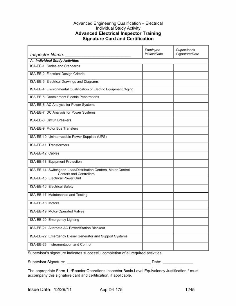
Advanced Engineering Qualification – Electrical Individual Study Activity
Issue Date: 12/29/11 App D4-175 1245
Advanced Electrical Inspector Training Signature Card and Certification
Inspector Name: __________________________________
Employee Initials/Date
Supervisor=s Signature/Date
A. Individual Study Activities
ISA-EE-1 Codes and Standards
ISA-EE-2 Electrical Design Criteria
ISA-EE-3 Electrical Drawings and Diagrams
ISA-EE-4 Environmental Qualification of Electric Equipment /Aging
ISA-EE-5 Containment Electric Penetrations
ISA-EE-6 AC Analysis for Power Systems
ISA-EE-7 DC Analysis for Power Systems
ISA-EE-8 Circuit Breakers
ISA-EE-9 Motor Bus Transfers
ISA-EE-10 Uninterruptible Power Supplies (UPS)
ISA-EE-11 Transformers
ISA-EE-12 Cables
ISA-EE-13 Equipment Protection
ISA-EE-14 Switchgear, Load/Distribution Centers, Motor Control Centers and Controllers
ISA-EE-15 Electrical Power Grid
ISA-EE-16 Electrical Safety
ISA-EE-17 Maintenance and Testing
ISA-EE-18 Motors
ISA-EE-19 Motor-Operated Valves
ISA-EE-20 Emergency Lighting
ISA-EE-21 Alternate AC Power/Station Blackout
ISA-EE-22 Emergency Diesel Generator and Support Systems
ISA-EE-23 Instrumentation and Control
Supervisor’s signature indicates successful completion of all required activities. Supervisor Signature: _______________________________________ Date: ______________ The appropriate Form 1, AReactor Operations Inspector Basic-Level Equivalency Justification,@ must accompany this signature card and certification, if applicable.
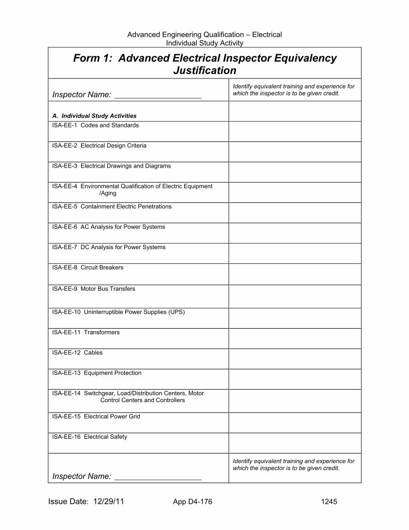
Advanced Engineering Qualification – Electrical Individual Study Activity
Issue Date: 12/29/11 App D4-176 1245
Form 1: Advanced Electrical Inspector Equivalency Justification
Inspector Name: __________________________
Identify equivalent training and experience for which the inspector is to be given credit.
A. Individual Study Activities
ISA-EE-1 Codes and Standards
ISA-EE-2 Electrical Design Criteria
ISA-EE-3 Electrical Drawings and Diagrams
ISA-EE-4 Environmental Qualification of Electric Equipment /Aging
ISA-EE-5 Containment Electric Penetrations
ISA-EE-6 AC Analysis for Power Systems
ISA-EE-7 DC Analysis for Power Systems
ISA-EE-8 Circuit Breakers
ISA-EE-9 Motor Bus Transfers
ISA-EE-10 Uninterruptible Power Supplies (UPS)
ISA-EE-11 Transformers
ISA-EE-12 Cables
ISA-EE-13 Equipment Protection
ISA-EE-14 Switchgear, Load/Distribution Centers, Motor Control Centers and Controllers
ISA-EE-15 Electrical Power Grid
ISA-EE-16 Electrical Safety
Inspector Name: __________________________
Identify equivalent training and experience for which the inspector is to be given credit.

Advanced Engineering Qualification – Electrical Individual Study Activity
Issue Date: 12/29/11 App D4-177 1245
ISA-EE-17 Maintenance and Testing
ISA-EE-18 Motors
ISA-EE-19 Motor-Operated Valves
ISA-EE-20 Emergency Lighting
ISA-EE-21 Alternate AC Power/Station Blackout
ISA-EE-22 Emergency Diesel Generator and Support Systems
ISA-EE-23 Instrumentation and Control
Supervisor=s Recommendation Signature/Date _____________________________________ Division Director=s Approval Signature/Date _____________________________________
Copies to: Inspector Human Resources Office Supervisor
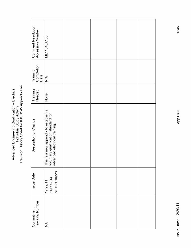
Adv
ance
d E
ngin
eerin
g Q
ualif
icat
ion
– E
lect
rical
In
divi
dual
Stu
dy A
ctiv
ity
Issu
e D
ate:
12/
29/1
1
App
D4-
1
12
45
Rev
isio
n H
isto
ry S
heet
for
IMC
124
5 A
ppen
dix
D-4
Com
mitm
ent
Tra
ckin
g N
umbe
r Is
sue
Dat
e D
escr
iptio
n of
Cha
nge
Tra
inin
g N
eede
d T
rain
ing
Com
plet
ion
Dat
e
Com
men
t R
esol
utio
n
Acc
essi
on N
umbe
r
NA
12/2
9/11
CN
11-
044
ML1
0301
0228
Thi
s is
a n
ew a
ppen
dix
to e
stab
lish
a vo
lunt
ary
qual
ifica
tion
stan
dard
for
adva
nced
ele
ctric
al t
rain
ing.
Non
e N
/A
ML1
1340
A1
30