‘imaka: a one-degree high-resolutionimagerforthe canada ... · the impact of such an instrument...
TRANSCRIPT

‘Imaka: a one-degree high-resolution imager for the
Canada-France-Hawaii Telescope
Mark R. Chun*a,
Raymond G. Carlbergb, Harvey B. Richerc, Yannick Mellierd, Pierre Astiere,
Olivier Lai, Derrick A. Salmon, Jean-Charles Cuillandref,
David Andersen, John Pazder, Jean-Pierre Verang,
Gregory A. Barrick, Steven Bauman, Kevin K. Hof,
Remy Avilah,Richard W. Wilson, Timothy Butterleyi
‘Imaka science team
aUniversity of Hawaii (USA); bUniv. of Toronto (Canada); cThe Univ. of British Columbia(Canada); dInstitut d’Astrophysique de Paris (France); eIN2P3 (France)
fCanada-France-Hawaii Telescope (USA); gNational Research Council Canada (Canada);hUniv. Nacional Autonoma de Mexico (Mexico); iDurham Univ. (United Kingdom)
ABSTRACT
The ‘Imaka project is a high-resolution wide-field imager proposed for the Canada-France-Hawaii telescope(CFHT) on Mauna Kea. ‘Imaka takes advantage of two features of the optical turbulence above Mauna Kea:weak optical turbulence in the free-atmosphere and boundary layer turbulence which is highly confined within asurface layer tens of meters thick and or the telescope enclosures. The combination of the two allows a ground-layer adaptive optics system (GLAO) to routinely deliver an extremely-wide corrected field of view of one-degreeat an excellent free-atmosphere seeing limit at visible wavelengths. In addition, populating the focal-plane withorthogonal-transfer CCDs provides a second level of image improvement on the free-atmosphere seeing and theresidual GLAO correction. The impact of such an instrument covers a broad range of science and is a naturalprogression of CFHT’s wide-field expertise.
Keywords: adaptive optics, wide-field imaging, ground-layer
1. INTRODUCTION
The Canada-France-Hawaii Telescope (CFHT) is located at one of the premier sites in the world for ground-based astronomy and while the superb seeing on Mauna Kea has long been known, a delivered image qualitycommensurate with the site has yet to be fully realized even at the most modern facilities on the summit.Numerous optical turbulence studies?,?,? at Mauna Kea have found excellent free-atmosphere seeing above thesite and recent studies? find that the turbulence within the boundary layer (e.g. first kilometer) is confinedto just the first tens of meters. This ground layer is roughly equal in strength to the free-atmosphere seeingso nearly half of the optical turbulence arises within a few tens of meters of telescope. In addition, studies atCFHT? have found that the dome seeing is particularly strong. A facility that is able to negate this local seeingwould produce unprecedented resolutions over these large fields of view. ‘Imaka is a path to achieve this onCFHT.
Aptly named after the Hawaiian word imaka meaning scenic viewpoint∗, ‘Imaka deploys a combinationof technologies to remove the local optical turbulence: a ground-layer adaptive optics system, a focal-plane
*MC: University of Hawaii, Institute for Astronomy, 640 N. Aohoku Place, Hilo, HI, USA; [email protected]∗http://www.wehewehe.org

consisting of orthogonal-transfer CCDs (OTCCD), and a new set of optics capable of delivering high-resolutionimages. In addition, ‘Imaka will benefit greatly from the gains made by CFHT’s current efforts to vent thetelescope enclosure. This mixture of active and passive approaches to mitigate the local degradations will deliverwide corrected fields of view, angular resolutions 2-3 times better than the current CFHT/MegaCam wide-field imager, and point-source sensitivities comparable to that of current 8-10 meter class telescopes. Opticalturbulence measurements at the site along with simulations of the performance of a ground-layer adaptive opticssystem with an OTCCD focal plane indicate that ‘Imaka will deliver angular resolutions of FWHM ∼ 0.3′′ atvisible wavelengths (e.g. r-band/0.7 microns) over a one-degree field of view. The delivered image quality varieswith wavelength with better performance at redder wavelengths and worse performance at bluer wavelengths.Notably, the angular resolutions are within a factor of 2-3 of that of the Hubble Space Telescope but with a fieldof view nearly 400 times larger than ACS/WFC3. The potential is striking and the scientific impact covers abroad range of areas from the Solar System to the most distant objects in the universe.
In this proceeding we present the conclusions of the ‘Imaka feasibility study we made for CFHT. We presentthe science impact and examples from the science case as well as resolutions of the key technical feasibilityquestions: (1) Is an opto-mechanical design for the instrument that meets the basic instrument performance andfunctional requirements feasible?, (2) Can we confirm and quantify that the image quality at CFHT is dominatedby local seeing and that the free-atmosphere seeing is low?, and (3) Do we understand the key error terms for aGLAO system with this extreme field size and wavelength range?. More information on the study can be foundin contributions in these proceedings by Lai et al. (performance simulations), Evans et al. (optical design), andthe study report (http://www.cfht.hawaii.edu/en/projects/IMAKA/).
2. SCIENCE CASE
‘Imaka is a general-purpose imager with an unmatched combination of angular resolution and field. While itdraws on techniques and technologies developed for advanced adaptive optics systems, ‘Imaka’s field and angularresolution link its science to that of wide-field imaging and survey facilities. The science cases remain trueto CFHT’s current scientific legacy in wide-field imaging spanning the Solar system, stellar physics, galacticstructure, galaxy evolution, and cosmology. ‘Imaka’s unique combination of high angular resolution and field ofview will provide a new avenue for discovery.
As a concrete illustration of the gain brought by ‘Imaka, we compare the current CFHT/MegaCam imager toCFHT with ‘Imaka. Taking into account the expected resolutions ‘Imaka will obtain (see Section ??), the gain inquantum efficiency at longer wavelengths from more modern CCD devices, and the expected optical throughputsof the ‘Imaka, we find that there is a sensitivity gain of between 0.7-1.8 magnitudes from g-band (0.45 microns)to z-band (0.9 microns) of ‘Imaka over the current MegaCam respectively. In addition, if ‘Imaka deploys red-senstitive CCDs, the Y -band (1.0 microns) photometric window is opened but with a loss of the u-band windowwith respect to MegaCam. The comparison can also be expressed in terms of the speed at which ‘Imaka cancover the sky to a given depth (”survey speed”). The roughly 1000-hours spent observing the 4-square degreeCFHT Legacy Survey Deep fields in g, r, i, and z (with depths of about rAB ∼ 28.4) could be done in nearlyan order of magnitude less time with ‘Imaka. While impressive, ‘Imaka must be considered within the contextof more modern facilities that will be functional in the coming years.
Wide-field optical imaging is truly a burgeoning domain with many high profile facilities expected to come on-line over the next decade. In some cases these facilities are competitive capabilities (e.g. Subaru/HyperSuprimeCam,PanStarrs4, and LSST) while others are complementary (e.g. TMT, JWST, EUCLID). It is instructive to quan-tify this comparison. The typical wide-field imager metric of etendue = AΩ, expressing how fast a facility cancover area, does not account for ‘Imaka’s gain in angular resolution. Indeed, etendue does not distinguish ‘Imakafrom CFHT’s current MegaCam. On the other hand, the Strehl ratio, a typical performance metric used foradaptive optics systems, does not account for ‘Imaka’s four orders of magnitude gain in field of view over classicalAO systems. In fact, the Strehl of ‘Imaka is essentially zero given the relatively large residual wavefront phaseerrors from the free-atmosphere.
We adopt a slight evolution of etendue to a more tangible metric to evaluate the relative performance offacilities covering large areas of sky with good image quality. Here we use a metric that quantifies the rate at

which information, namely the signal-to-noise ratio for background-limited point sources, is collected over thefield of view. We express this as:
FOM =AΩ
IQ2 , (1)
where A is the collecting area of the telescope, Ω is the field of view, and IQ is the delivered image quality onthe focal plane.
Table ?? shows the growth of this figure of merit for current and future ground-based optical wide-field im-agers. ‘Imaka’s competition comes from the significantly larger projects such as Subaru/HyperSuprimeCam andLSST. Here the telescope apertures and field sizes beat ‘Imaka in terms of collecting signal on sources over largefields. We note also that, while having a very different science objective, the Gemini multi-conjugate adaptiveoptics system (GEMS?) with its 80-arcsecond diameter field of view and diffraction-limit angular resolutions inH-band (1.65 microns) has a normalized figure of merit of 0.5. Similarly, a multi-object adaptive optics (MOAO)system, while providing a diffraction-limited image does so for very small fields (discrete objects) within a largerfield and thus has a very small figure of merit. It is clear, however, that the scientific objective of these systemsvaries drastically from the ‘Imaka case.
Table 1. A comparison of a variety of existing or planned ground-based wide-field imaging facilities for the FOM = AΩ
IQ2 .In the table the quantity Deff is the square root of the collecting area of the telescope and DIQ is the delivered imagequality at the facility. Note that the figure of merit is normalized by that for CFHT/MegaCam.
Instrument Year Site Deff FOV DIQ Metric(meters) (degrees2) (arcsec) (normalized)
PS1 2009 Haleakala 1.6 7.30 1.0 0.9MegaCam 2003 Mauna Kea 3.5 1.0 0.75 1.0ODI 2012 Kitt Peak 3.3 1.0 0.60 1.4SuprimeCam 2002 Mauna Kea 8.1 0.25 0.65 1.8PS2 2012 Haleakala 1.6 7.30 0.7 1.8DEC 2012 Cerro Tololo 3.9 3.0 0.95 2.3‘Imaka 2016 Mauna Kea 3.5 0.8 0.3 5.0HyperSuprimeCam 2012 Mauna Kea 8.0 1.5 0.65 10.4PS4 ???? Mauna Kea 3.1 7.3 0.55 10.6LSST 2016 Cerro Pachon 6.7 9.6 0.7 40.4
Even with the improved metric, Table ?? does not take into full consideration the fact that ‘Imaka will deliveran angular resolution unique to all the ground-based wide-field imaging facilities in the coming decade. Here acomparison with space-based missions may be more appropriate. In particular, we call out the NASA/JDEMand ESA/EUCLID missions. Both projects are designed for weak lensing and are expected to provide stablehigh quality images with wide-field optical imagers on 1-2 meter class telescopes. It is not clear when JDEMwill be operational but EUCLID is expected to fly in 2019. However, in its present design Euclid has only onevery broad visible filter (r+i+z) for ellipticity measurements and will rely on multi-band wide-field surveys inthe visible from the ground. Therefore 0.3-arcsecond wide-field visible surveys with ‘Imaka would turn out to bevery useful for Euclid, in particular for the the g and r-band data. Until 2019, ‘Imaka will therefore outperformany other wide-field instrument on the image quality front but will still be valuable for ground based follow uplater on.
‘Imaka’s uniqueness is in the combination of field and resolution. In addition, operationally many of thesefacilities will be dedicated to large surveys. Access for P.I. driven programs will be limited. Here CFHT’scommunity’s experience in wide-field imaging will be a key benefit to tap the capabilities of ‘Imaka.
2.1 Science Case Examples
As a concrete example of the unique science that ‘Imaka can enable, we present one of the science cases from the‘Imaka Feasibility study (http://www.cfht.hawaii.edu/en/projects/IMAKA/): Resolved stellar populations in

nearby galaxies out to the Virgo cluster. For this case, the angular resolution allows us to resolve the individualstellar populations within the galaxies, the multi-band wavelength coverage provides the spectral information tocharacterize the populations, and the field coverage allows a complete census of the galaxy and it’s environmentto be made without worries of selection effects or the mis-choice of unrepresentative fields within the galaxy.
Many of the key predictions of galaxy formation theories - such as the spatial distribution and morphology ofthe structure and substructures in the outer regions of galaxies - are only testable for the nearby Universe. Thusobservations of the stellar populations of these galaxies provide direct tests of and constraints on cosmologicalmodels of galaxy formation. New surveys in both the Milky Way (e.g. SDSS) and M31 (e.g. PAndAS) haverecently uncovered a spectacular panorama of the complex outer regions of galaxies, with a plethora of dwarfgalaxies, stellar streams and diffuse structures. The luminosity function of these dwarf galaxies and the expecta-tions from simulations of galaxy formation indicate that many more lower luminosity dwarfs exist. ‘Imaka offersa wide field of view with increased sensitivity, ideally suited to finding these compact objects in a large stellarhalo such as M31. A more complete census of dwarf galaxies directly confronts hierarchical cosmological modelson small scales. The sharper PSF will also allow the giant and horizontal branch populations of these galaxies tobe traced into the core, and therefore lead to a much more detailed analysis of the structural properties and radialgradients of these systems. Such data, even for the currently discovered satellites, will aid in our interpretationof the causes of the different properties of the satellite system (both internally and when comparing Milky Waydwarfs to M31 dwarfs). For example, it is still unclear whether the observed differences are caused by in situprocesses within the dwarf satellites or through dynamical interactions with the host.
Pushing to more distant galaxies in the local volume – where there is a statistically larger sample of galaxiesover a full range of morphological type – requires wide field capabilities with high spatial resolution to overcomecrowding issues, and demonstrates the need for wide-field AO capabilities on large telescopes that approachthe diffraction limit. ‘Imaka will extend the science which is currently only possible in the Local Group to all
galaxies within 10Mpc. At 10Mpc, the 1 square degree field corresponds to 175kpc. Such data would allow oneto measure the spatial structure of extra-planar stars, measure axial ratios, map halo flattening to very faintisophotes, determine the metallicity distribution of halo stars and their spatial variation, search for substructuresor clumpiness due to tidal streams or dissolving dwarf galaxies, measure structural parameters of globular clustersand find asymptotic giant branch (AGB) stars associated with intermediate-age stellar populations. A hint ofthings to come can be seen in the recent paper by Mouhcine et al (2010)? where spectacular unexpected structure(a giant stream, a large flat cocoon-like structure out to 40 kpc from the galaxy) was discovered surroundingNGC 891 from Subaru imaging. This galaxy is located at 10 Mpc from the Milky Way and records details of halostructure formation at distances well outside the Local Group. Observations of this sort will answer questionssuch as did galaxies accrete most of their mass/stars at early or late times? How many mergers does a typicalgalaxy undergo? What is the lowest mass dwarf galaxy which can form stars? Currently,these questions arerestricted to the Milky Way, M31 and M33. ‘Imaka will be able to probe the outer haloes of these latter galaxiesto typically 35 mag/sq. arcsec - at least one magnitude deeper than current CFHT/MegaCam studies. Obtaininga significant sample of resolved stellar halos to low surface brightness is central to advancing cosmological modelsof galaxy formation. ‘Imaka will provide a new perspective on our nearest neighbors. For this work, it will benecessary to measure at least the top 1 magnitude of the RGB out to 10Mpc. At that distance the RGB tipoccurs at i = 25.8, so we require data that reach i = 26.8, g = 28 with S/N ∼ 10.
Current HST-based projects are probing some nearby galaxies with these science goals, but all are placed at aserious disadvantage due to the impossibility of observing a large fraction of the area of nearby galaxies with the(relatively) small field of ACS/WFC3. High resolution wide field cameras such as ‘Imaka are an essential pre-requisite for this science. A lesson learned from these surveys is that no firm conclusions regarding the propertiesof the outskirts of galaxies can be drawn from observations sampling unrepresentative galactic volumes. Aneloquent example of this is the single pointing ultra-deep ACS observations of a minor-axis field in the halo ofM31 that was realized later to fall close to a highly disturbed and clumpy structure discovered in the panoramicsurvey of M31. Panoramic coverage provides the only avenue to unlock the secrets of the outskirts of galaxies,and to fully exploit what they have to tell us about galaxy assembly.
3. INSTRUMENT CONCEPT
The instrument concept for ‘Imaka has changed significantly from that presented in Lai et al.? The basicperformance and functional requirements, nonetheless, have stayed largely unchanged.
Top-Level Performance Requirements
1. Field of view : 1 degree diameter or equivalent solid angle
2. Wavelength Range : 0.4 to 1.1 micron
3. Delivered image quality of 0.3” or better at r-band under median seeing conditions with a FWHM uniformwithin 10% over entire field
4. Photometric measurements with an accuracy of 1% absolute and 0.1% relative
5. Astrometric measurements with an accuracy of 40mas absolute and 0.8 mas relative
6. Sky coverage 100% in Galactic plane and > 50% at North Galactic Pole
Top-Level Functional Requirements
1. A GLAO system with (1) wavefront sensors that sense the wavefront aberrations that arise from effectsnear the ground and (2) a DM that corrects this wavefront across the field.
2. A focal-plane camera providing local tip/tilt wavefront corrections
3. ‘Imaka can not preclude the use of other CFHT facility instruments
4. Access to the CCD camera and DM systems should be provided with ‘Imaka on the telescope.
5. An exchange to ‘Imaka should be completed in less than one working day
The instrument concept has evolved into two possible configurations: ‘Imaka-Prime a two-channel primefocus design and ‘Imaka-Cassegrain: a double-pass transmissive design at the Cassegrain focus. Given the largefield size and high image quality, both designs are large in scale and will need either a dedicated upper endor full access to the volume behind the primary mirror cell. In addition to the imaging optics, we requirethat the CFHT telescope be kept in roughly its current operational configuration. In particular, it must becompatible with existing or currently planned instrumentation. A new telescope top end is consistent with thisrequirement though changes to the cassegrain focus optical prescription is likely not. To support the GLAOcorrection, we also require that the instrument have (1) a well defined and accessible intermediate telescopepupil where an deformable mirror (DM) can be placed and (2) a set of approximately 6-8 wavefront sensorsthat can be deployed about the field. To support the additional tip/tilt correction in the free-atmosphere, werequire a CCD camera system based on orthogonal transfer (OT) technology with a broad wavelength coverage.Given the desire to have use wide bandpasses for the science and the sharp image quality, ‘Imaka will alsorequire an atmospheric dispersion corrector. Finally, as with previous instrumentation at CFHT, ‘Imaka willneed an instrument calibration and data reduction pipeline to provide astronomy-ready images with instrumentalsignatures removed.
With the limited resources for the feasibility study we concentrated on those issues that pose the largestquestions for its feasibility. Other, better understood issues, where technologies or current practices seem tobe better defined are left to Phase A engineering studies where more detailed design and systematic decisionswill start to be made. We therefore left details of the ADC, DM and control, wavefront sensors and the datapipeline in this latter category. From a technical stand point we identified the overall optical design, the in-situ turbulence measurements at CFHT, and quantifying the major GLAO error terms as the critical technicalquestions to address in the feasibility study. In this section we present the two optical designs and in the twosections that follow we present the turbulence measurements and simulation results.

3.1 Optics
The biggest challenge in the optical design was to determine, given the field size, whether or not a design was evenfeasible. The initial concept using a deformable secondary mirror was discarded once the impact on the deliveredperformance of the misconjugation of the secondary mirror (hDM ∼ −43 meters) was quantified. The top levelinstrument requirements flow from the ‘Imaka science cases and functional limitations imposed by the telescope.Given these requirements, the optical designers were faced with the following challenges and constraints:
• Provide images with 80% encircled energy diameters 0.15 arcsec (or better) across a field 1 degree indiameter (or equivalent) for each spectral band (e.g. g,r,i,z,Y)
• Deliver a final f/5.7-f/6.8 optical beam to match the desired image sampling of 0.1 arcsec per pixel for anorthogonal transfer CCD with a 10-12 micron pixel pitch.
• Provide access at a well defined pupil image to locate an adaptive optical element (DM) working at anincident angle of less than 20 degrees and conjugate to a zone between 15 m below the primary mirror to30 m above the primary mirror (see Lai et al. 2010 these proceedings).
• Locate optical and CCD camera components at accessible locations on the telescope
• If at the Cassegrain focus, pass the beam through the primary mirrors central hole.
• Use refractive materials (if any) that are available commercially at the required sizes.
The optical design requirements pose a serious design challenge. The needs for a large focal surface ( 360mm diameter), and for an adaptive element near a pupil image, requires ‘Imaka to be physically large. A furtherconstraint of the large focal surface is that in order to feed light to an array of wavefront sensors with minimalvignette of the science focal plane we will need to place wavefront sensor pickoff mirrors very close to the finalfocal surface. As a result, the wavefront pickoffs may be located behind the optical bandpass filters placingconstraints on guide star availability.
Because of the difficulty inherent to the ‘Imaka optical design problem we engaged the services of 6 opticaldesigners familiar with designing high performance optical systems for astronomical facilities over sixteen designvariants. Of these, the following two concepts (‘Imaka-Prime and ‘Imaka-Cassegrain) meet the core requirementsof image quality, field size, pupil image quality, conjugation and focal surface access.
3.1.1 Prime Focus Design
The prime focus design by Clinton Evans and Hua Lin (Evans et al. 2010 these proceedings) splits the field intotwo rectangles measuring 0.4 degrees x 1.0 degree with centers separated by 2 degrees on the sky. Two separateand independent optical systems together providing areal sky coverage equivalent to a one degree diameter field,are mounted outboard of the telescope top ring.
The all-reflective design, one channel of which is illustrated on the left in Figure ??, uses 2 flat mirrors, 2aspheres and a mildly convex spherical DM 260 mm in diameter. The two channels mount to a dedicated upperend. The aspheres are large, 65 cm and 90 cm respectively, which will make fabrication and testing expensive.In addition, the focal surface is curved (r = 1.6 m) but can accommodate flat 4k x 4k OTCCDs without seriousIQ degradation if they are offset in focus in steps of 60 um. As currently laid out, each unit will vignette a smallportion of the others pupil as well as an even smaller portion of its own pupil. The effects are small and amountto an surface area loss of less than the current CFHT/MegaCam configuration.
The key advantages of this design are: (1) its reflective design is the achromatic, (2) it minimizes of thenumber of surfaces that can give rise to ghosts, and (3) its two-channel approach has inherent redundancy. Thekey disadvantages are the large aspheric optics and the need for two largely independent GLAO systems.
A more in-depth discussion of the Prime focus design and its performance can be found in Evans et al (2010,these proceedings).

Figure 1. Left: One side of the ‘Imaka prime focus design (Evans et al. 2010 these proceedings). The light coming fromthe CFHT primary mirror is reflected of a flat secondary mirror (iM1) and sent towards the outer ring of the telescope.There two aspheres (iA1, iA2), the deformable mirror (DM), and a last fold mirror (iM2) bring the light to the sciencefocal plane (CCD). Not shown are the wavefront sensor or ADC optics. Right: A 3D CAD rendering of the ‘Imaka-Primelayout showing the two channels at the top of the CFHT 3.6-m telescope.
Figure 2. Left: The optical path of the ‘Imaka Cassegrain focus design by John Pazder (HIA). The light coming fromthe CFHT f/10 focus is sent through a three-element system (L1-L3), then double-passed through a set of four lenses(L4-L7) with the retro-reflection occuring at the DM surface. Right: A 3D CAD rendering of the ‘Imaka-Cassegrainlayout showing the lenses and bottom end of the CFHT 3.6-m telescope. The large L4 and L5 lenses are roughly 1.2m x0.8m in size.

3.1.2 Cassegrain Focus Design
John Pazder at HIA developed a design for the Cassegrain focus based on a Wynne-Dyson double-pass designthat has a contiguous, on-axis one degree diameter field. The design is rather unique since several lenses are useddouble pass with the entrance beam passing to one side of lens center and the exit beam from the DM passingthrough the opposite side of the lenses (Figure ??). This design has not benefited from the level of optimizationevident in the ‘Imaka prime focus design, but still meets many of the design requirements. The design usesmostly refractive optics, except for the DM and a fold mirror. The 400 mm diameter DM has the advantage ofbeing at the telescope pupil and slightly concave which facilitates testing. There is ample room for an ADC,filters, and wavefront sensors in the optical path. The full one degree beam diameter (470 mm) easily passesthrough the primary mirrors central hole (680mm) with clearance. Three lenses are mounted either inside theprimary mirror cell or in the primary mirrors central hole.
The design’s key advantages are that the image quality is excellent across the one-degree diameter field ofview and the pupil image is sharp (less than 2% pupil distortion in the worst case) with the DM positioned atthe telescope pupil. The designs chief drawbacks are its very large size and thus its weight, several very largelenses, 22 air-glass interfaces without counting the ADC, filter or cryostat window, a refigured secondary mirror,and the loss of the Cassegrain Bonnette which will need to be removed, probably on a permanent basis.
While both optical designs meet the basic performance and functional requirements they differ significantlyin all other means. As a result, we will need to down-select the optical design early in the Phase A study.
3.2 GLAO
The details of the GLAO design have not been a high-priority during the feasibility study with the exceptionof constraining the DM altitude conjugation and the allowable tilt of the DM with respect to the optical axis.In addition basic simulations for the order of the system (10x10 to 20x20 actuators) and the effects of guideasterisms were made. We see the engineering challenges for the next phase of the study to be: (1) the controlalgorithms and wavefront reconstruction and (2) the necessity for multiple deployable wavefront sensors. Wenote that while the acquisition system for the wavefront sensors could be simplified if the system used laser guidestars (for example multiple Rayleigh beacons), the additional complexities of deploying multiple lasers and itsassociated launch facility are viewed as incompatible with the CFHT model of operation. Given the large fieldsof view, the sky coverage with natural guide stars permits the use of natural stars for 6-8 guide stars.
The hardware for the individual components largely exists already. The individual wavefront sensors aresimilar to wavefront sensors operating in AO systems today. The deformable mirrors are larger than typicalDMs and also have slightly curved (spherical) surfaces. At least one DM manufacturer feels these DMs arewithin their current capabilities. The real-time AO controller must process many subapertures and will benefitfrom a tomographic wavefront reconstructor. So while the system loop sampling rate to handle the ground-layerand dome seeing is expected to be lower than typical AO systems, the wavefront reconstruction may benefit fromdedicated hardware wavefront reconstruction solutions such as those envisioned for the AO systems on extremelylarge telescopes such as TMT.
3.3 OTCCDs
Orthogonal transfer CCDs? provide the means to shuffle charge between adjacent pixels at high transfer rateswhile continuing to collect charge. Operationally, bright stars within the field are identified and the pixels withinthe individual cell of pixels (typically 600x600 pixels) around these stars are readout at high sub-frame rates(e.g. 30Hz) to determine the real-time jitter errors. These guide star signals are then fed back to the rest ofthe detector cells to shuffle their charge appropriately. This provides a focal-plane solution to residual wavefronttip/tilt errors. Corrections for the atmospheric wavefront tilt are made over individual isokinetic patch regions ofthe sky (arcminutes in size) and the telescope tracking/jitter errors are also reduced. The maturity of OTCCDsis rapidly advancing with detectors in operation at the UH2.2m telescope on Mauna Kea and at the 3.5-meterWIYN telescope on Kitt Peak. In addition, the PanSTARRS? and WIYN/One-Degree imager? (ODI) projectshave/are populating large focal planes with OTCCDs. ‘Imaka is a natural progression of these projects and thebaseline focal-plane array is very similar to the PanSTARRs-1 and ODI giga-pixel cameras.

As with the GLAO components, the OTCCD and the camera/control electronics were not perceived asfeasibility concerns since the PS1? and ODI cameras requirements are very similar to that needed for ‘Imaka.Of note however for the ‘Imaka OTCCDs are two outstanding issues. First, while the Optic? and the QUOTA?
cameras have demonstrated the performance and gains of OTCCD for astronomical observations, charge shufflingfor the very large arrays and fields of view (e.g. PS1 and ODI) and the optimal use of the guide signals and pixelcontrol must be done. Since roughly half the fields at the North Galactic Pole (NGP) will not have enough bright,isolated stars to fully sample all the iso-kinetic patches (a few arcminutes in size) over one degree field of view,the optimal use of the available guide stars is a key question. In fact the sky coverage for full GLAO+OTCCDcorrection is driven by the need for sufficient OTCCD guide stars ( 150) rather than the GLAO correction.The second consideration for ‘Imaka’s choice of OTCCD sensors rests in the desired wavelength coverage. The‘Imaka science case calls for a broad wavelength coverage but the current OTCCD detectors are either ”thick” andoptimized for red wavelengths (e.g. 0.45− 1.1 microns) or ”thin” and optimized for blue wavelengths (0.35− 0.9microns). Given that the resolutions achieved with the GLAO and OTCCD are best at the red wavelengths andthat the ODI camera will be using the blue-sensitive detectors, we expect that ‘Imaka will be optimized for thereddest wavelengths.
4. SITE CHARACTERISTICS
The ‘Imaka concept works because the delivered image quality is degraded largely by optical turbulence withina volume close to the telescope and/or ground. The CFHT MegaCam image quality study? and the Geminiground-layer study? show that this is indeed the case for CFHT on Mauna Kea. Salmon et al.? deduce therelative contributions to the delivered image quality of MegaCam images due to a variety of sources and theyfind that the largest local degradations come from dome seeing (0.43” at 0.5 microns) and the telescope staticoptical aberrations (0.33” at 0.5 microns). Using an optical turbulence profiler, Chun et al.? found that theatmosphere above the summit of Mauna Kea has a very thin, 30-40 meter thick layer of optical turbulence justabove the ground and very little optical turbulence elsewhere in the boundary layer (e.g. first kilometer). Finally,multiple studies?,? have found that the free-atmosphere seeing above Mauna Kea is excellent (0.35-0.4” FWHMat 0.5 microns). All of these results suggest that GLAO on CFHT will provide a significant improvement to thedelivered image quality of the facility over a very wide field of view.
For the feasibility study of ‘Imaka we set out to (1) confirm the findings from Salmon et al? and Chun etal.? using an optical turbulence profiler on the CFHT telescope and (2) to quantify the distribution and spatialand temporal characteristics of the optical turbulence in and just outside the dome for input into the ‘Imakaperformance simulations/error budget. To do this we’ve begun a two-staged experiment. The first phase ofthe optical turbulence profiler (OTP1), now deployed at a bent-Cassegrain port on CFHT, consists of a singleShack-Hartmann wavefront sensor that measures the wavefront tilts over a one-meter off-axis portion of theCFHT primary.
OTP1 resides at a bent-Cassegrain port of the CFHT and is configured to be a 20x20 subaperture Shack-Hartmann wavefront sensor using a square 1 meter x 1 meter portion of the CFHT primary mirror. It collectsdata, typically for 15 minutes, on nights when CFHT’s Cassegrain science instrument (ESPANDONS) is beingused. With a single star WFS an ambiguity remains on the altitude at which the turbulence arises. However,the phase power spectrum of the turbulence shows a bimodal distribution of temporal frequencies for the phaseaberrations (Figure ??). We identify (but have not confirmed) the low temporal frequency power (f ∼ 0.1Hz) asarising within the dome and the high frequency power as the atmospheric component. We have some assurancethat this is the case for at least a few nights when we ran an optical turbulence profiler outside the CFHTfacility in addition to OTP1. For these nights we can identify distinct layers in the slope/phase temporal cross-correlations. Two distinct layers are common to both experiments while an additional low temporal frequencycomponent is seen only in the CFHT/OTP data. specific to CFHT.
For now, making a somewhat arbitrary cut at 1Hz in the phase power spectra to to distinguish ”dome seeing”and ”atmospheric seeing”, we find that the optical turbulence arising within the dome is significant and often thedominant contribution. On average we find over the 56 nights sampled to date that the low- temporal frequencycomponent (f < 1Hz) is equal to or even slightly larger than the high- frequency component (f > 1Hz). All

Figure 3. Two examples of the power spectral density of Zernikes 4/5 from OTP1. The data are shown in black whilefive-layer fits are shown in red. The data is shown in f*psd(f) versus log(f) as in Roddier et al. (1995) where the areaunder the curves are proportional to the total variance in the layer. The blue curve shows the residual after the model fit.The two nights show dramatically different distributions in frequency space. The 2009-09-03 data appears to be nearlyentirely due to dome seeing while the atmospheric seeing dominates in the 2009-09-28 data set. The normal distributionis a more balanced mixture of the two.
studies (here with OTP, Salmon et al.,? and Racine et al. (1991)? find similar fractions of contributions fromthe dome (∼ 0.45”) and atmosphere (∼ 0.45”).
In the second phase of OTP, we will deploy a true profiler (e.g. SLODAR/LOLAS) at the CFHT bent-Cassegrain port. These true profilers will obtain the turbulence altitudes directly and will help to remove anyfinal ambiguities in the origin of the turbulence.
Finally, we note that there are now a number of additional profilers and seeing monitors on the summit. Thereare two seeing monitors on the summit of Mauna Kea: the CFHT DIMM in the slit of the CFHT enclosure andthe summit facility Mauna Kea Atmospheric Monitor (MKAM). MKAM is a low-resolution optical turbulenceprofiler and seeing monitor (MASS/DIMM) sited at the location of the old CFHT/Gemini weather tower next toCFHT. This facility now provides the strength and distribution of atmospheric seeing on a nightly basis. Overthe course of the first few months of data with MKAM the median MASS seeing (essentially free-atmosphereseeing as it is measured from 500m and above) was measured to be 0.3”. This is in excellent agreement with paststudies at Mauna Kea. In addition, a high-resolution optical profiler (Lunar SHABAR) is being deployed in acampaign mode on the summit by Paul Hickson/Thomas Pfrommer (UBC) and will provide very high resolutionprofiles from inside the dome and at the MKAM site.
5. PERFORMANCE SIMULATIONS
In this section we present the highlights of the ‘Imaka performance simulations developed during the feasibilitystudy. The details of the simulations, and importantly the development of the effects of tilting the DM withrespect to the optical axis and the conjugation of the DM, are described in these proceedings by Lai et al..
A new simulation code specifically for ‘Imaka that incorporates a numbers of unique features was developed.The code includes a model of the atmospheric turbulence based on the Gemini Mauna Kea Ground-layer study,the effects of misconjugating and tilting a DM with respect to the optical axis, and the effects of the combinedcorrection from a GLAO system and the tip/tilt correction from an orthogonal-transfer CCD camera. The code(instantGLAO) was developed by Olivier Lai and has been extensively cross-compared for a number of casestudies with the yao and simul codes (Francois Rigaut), the LAOS code (Brent Ellerbroek/Luc Gilles), andPAOLA (Laurent Jollisaint). In addition, PAOLA has been modified to be used with ‘Imaka and is now beingused to develop a detailed baseline for the GLAO system. With instantGLAO we quantified the phase errorsdue to the tilt of the DM with respect to the optical axis and the optical conjugation of the DM with respect tothe optical turbulence. These errors place strong constraints on the ‘Imaka optical design and drove the opticaldesign away from an adaptive secondary due to its misconjugation altitude. This is a major change from theoriginal work.?
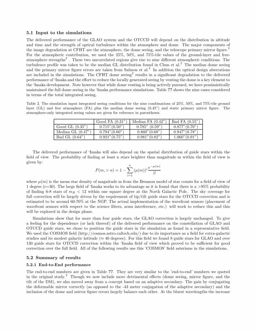
5.1 Input to the simulations
The delivered performance of the GLAO system and the OTCCD will depend on the distribution in altitudeand time and the strength of optical turbulence within the atmosphere and dome. The major components ofthe image degradation at CFHT are the atmosphere, the dome seeing, and the telescope primary mirror figure.?
For the atmospheric contribution, we used the 25%, 50%, and 75%-tile values of the ground-layer and free-atmosphere strengths? . These two uncorrelated regions give rise to nine different atmospheric conditions. Theturbulence profile was taken to be the median GL distribution found in Chun et al.? The median dome seeingand the primary mirror figure errors are taken from Salmon et al.? In addition the optical design aberrationsare included in the simulations. The CFHT dome seeing? results in a significant degradation to the deliveredperformance of ‘Imaka and the effort to reduce the locally generated seeing by venting the dome is a key element tothe ‘Imaka development. Note however that while dome venting is being actively pursued, we have pessimisticallymaintained the full dome seeing in the ‘Imaka performance simulations. Table ?? shows the nine cases consideredin terms of the total integrated seeing.
Table 2. The simulation input integrated seeing conditions for the nine combinations of 25%, 50%, and 75%-tile groundlayer (GL) and free atmosphere (FA) plus the median dome seeing (0.45”) and static primary mirror figure. Theatmosphere-only integrated seeing values are given for reference in parentheses.
Good FA (0.31”) Median FA (0.42”) Bad FA (0.55”)Good GL (0.35”) 0.715”(0.50”) 0.785” (0.59”) 0.877”(0.70”)Median GL (0.47”) 0.794”(0.60”) 0.860”(0.68”) 0.947”(0.78”)Bad GL (0.64”) 0.921”(0.75”) 0.981”(0.82”) 1.060”(0.91”)
The delivered performance of ‘Imaka will also depend on the spatial distribution of guide stars within thefield of view. The probability of finding at least n stars brighter than magnitude m within the field of view isgiven by:
P (m,> n) = 1−
n∑
i=1
(µ(m))ie−µ(m)
i!
where µ(m) is the mean star density of magnitude m from the Besanon model of star counts for a field of view of1 degree (r=30). The large field of ‘Imaka works to its advantage as it is found that there is a >95% probabilityof finding 6-8 stars of mR < 12 within one square degree at the North Galactic Pole. The sky coverage forfull correction will be largely driven by the requirement of tip/tilt guide stars for the OTCCD correction and isestimated to be around 60-70% at the NGP. The actual implementation of the wavefront sensors (placement ofwavefront sensors with respect to the science filters, arms interference, etc.) will work to reduce this and thiswill be explored in the design phase.
Simulations show that for more than four guide stars, the GLAO correction is largely unchanged. To givea feeling for the dependence (or lack thereof) of the delivered performance on the constellation of GLAO andOTCCD guide stars, we chose to position the guide stars in the simulation as found in a representative field.We used the COSMOS field (http://cosmos.astro.caltech.edu/) due to its importance as a field for extra-galacticstudies and its modest galactic latitude (≈ 40 degrees). For this field we found 8 guide stars for GLAO and over130 guide stars for OTCCD correction within the ‘Imaka field of view which proved to be sufficient for goodcorrection over the full field. All of the following results use this ’COSMOS’ field asterisms in the simulations.
5.2 Summary of results
5.2.1 End-to-End performance
The end-to-end numbers are given in Table ??. They are very similar to the ’end-to-end’ numbers we quotedin the original study.? Though we now include more detrimental effects (dome seeing, mirror figure, and thetilt of the DM), we also moved away from a concept based on an adaptive secondary. The gain by conjugatingthe deformable mirror correctly (as opposed to the -43 meter conjugation of the adaptive secondary) and theinclusion of the dome and mirror figure errors largely balance each other. At the bluest wavelengths the increase

in the total seeing included in the simulations degrades the performance significantly and will benefit greatlyfrom the dome venting program. We are also now including Y-band (1.0 microns) in the simulation runs as itwas identified as an important bandpass for the science cases.
Table 3. ‘Imaka End-to-End performance for the ‘Imaka-Cassegrain design in median(GL)/median(FA) atmospheric con-ditions including dome seeing and the primary mirror figure. The table shows the 25%, 50%, and 75%-tile FWHM over theone deg diameter FOV for five wavelengths of interest with GLAO-only correction and full GLAO+OTCCD correction.For reference, the input integrated seeing was 0.86” at 500 nm.
Science Wavelength GLAO-only GLAO+Full OTCCD(filter) FWHM (arcsec) FWHM (arcsec)
0.45 microns (b) 0.47, 0.49, 0.50” 0.39, 0.40, 0.42”0.5 microns (g) 0.44, 0.46, 0.48” 0.36, 0.38, 0.39”0.7 microns (r,i) 0.38, 0.40, 0.41” 0.29, 0.31, 0.32”0.9 microns (i,z) 0.35, 0.36, 0.38” 0.25, 0.27, 0.29”1.0 microns (Y) 0.34, 0.35, 0.37” 0.24, 0.25, 0.28”
5.2.2 How does the image quality vary across the field?
The performance, as measured by the FWHM, is remarkably uniform over the one degree field of view. For theCOSMOS field, eight GLAO guide stars were found near the periphery of the field and over 130 OTCCD guidestars were found within the one-degree diameter field of view. Figure 3 below shows a color-coding of the FWHMderived from an array of 60x60 PSFs (PSFs sampled every one arcminute) across the field. Positions of the eightGLAO guide stars are indicated by yellow stars while the OTCCD guide star positions are indicated by crosses.With an OTCCD focal-plane populated with OTCCDs the detector real estate immediately surrounding anOTCCD guide star is used for sensing the tip/tilt correction. As such, these areas are not accessible for science.The area lost to the OTCCD guide stars is about 1 square arcminute per guide star so in the case of the COSMOSfield, this amounts to less than 5% of the field. In addition, the areas surrounding the GLAO guide stars willbe vignetted by the GLAO WFS probe arms. These areas are also not accessible for science. Finally, the areavignetted by the WFS patrol arms will depend on the design of the WFS arms but the intent is to minimize thisobstruction.
Given that in some fields there will not be enough guide stars for full OTCCD correction over the fieldof view, we list the performance of both the GLAO-only (an extreme of no OTCCD guide stars) and fullGLAO+OTCCD cases. The OTCCD correction amounts to an improvement of about 0.1” in FWHM at allwavelengths. Comparing the GLAO-only and the GLAO+OTCCD PSF FWHM across the field seems to pointto the OTCCD contributing in two ways. First it removes the tip and tilt from the upper atmospheric layers.Second, it smooths out the GLAO performance by correcting for tilt anisoplanatism within the GLAO correction.We note that the OTCCD performance across the field depends on the altitude of the free-atmosphere layersand on how we combine information from multiple OTCCD guide stars to generate the correction signal. Herea simple averaging of the wavefronts is used (e.g. not tomographic). More advanced techniques will be pursuedin the Phase A study. We will also be using the MKAM MASS/DIMM seeing monitor to develop a betterturbulence model of for the free atmosphere.
5.2.3 Probability of obtain a particular image quality
For a particular observing time and location in the sky, the seeing and the number of appropriate guide stars willvary. For the range of atmospheric seeing considered (e.g. the quartile strengths of the ground-layer and free-atmosphere), we can derive rough probabilities that a particular combination will occur given that the turbulencein the ground-layer and free-atmosphere are uncorrelated. This gives rise to nine different seeing conditions used(outlined above in section ??). Figure ?? shows the median delivered image quality in the ‘Imaka field of view at0.7 microns given the range in atmospheric conditions, the median dome seeing value, the primary mirror figureerror, and the camera optical design aberrations.

Figure 4. Left: The distribution of FWHM across the one-square degree field at an imaging wavelength of 0.7 micronsfor median ground-layer and median free-atmosphere strengths. The one degree diameter field of the ‘Imaka-Cassegraindesign is shown as well as the positions of the GLAO guide stars (yellow stars) and the OTCCD guide stars (crosses).The sharp rise in the FWHM in the corners of the field are nearly entirely due to the optical design aberrations thatdegrades quickly outside the one-degree diameter. Right: The cumulative probability distribution of FWHM within theone-degree diameter field. The distribution of FWHM for the five wavelengths are shown. For each wavelength the 25%,50%, and 75%-tile FWHM in the field are noted next to the curve.
Figure 5. Cumulative probability distribution function for ‘Imaka for the adopted set of input seeing conditions. Thecurves show the probability that the median FWHM within the field will be less than or equal to a value for each ofthe five science wavelengths in question. The thin black line gives a reference for the input image quality (includingthe atmospheric seeing, the optical design, dome seeing, and mirror figure) for the ‘Imaka Cassegrain Wynne-Dysondesign at a wavelength of 0.5 microns. It should be comparable to the delivered image quality obtained with the currentCFHT/MegaCam imager though the best conditions are pessimistic while the worst conditions are optimistic whencompared to the actual image quality statistics for MegaCam. This is largely due to the fact that we have considered asingle (median) value for the dome seeing.

Figure 6. The shape of the ‘Imaka PSFs is shown by the symbols. These cuts were made on the average PSF withinthe field for the median(GL)/median(FA) case at wavelengths of 0.5, 0.7, and 0.9 microns. Three functional fits are alsoshown Gaussian (red), Moffat (green), and Lorentzian (blue).
5.2.4 Shape of the PSF
The ‘Imaka PSF is dominated by the residual free-atmosphere seeing and as such we expect the PSF will bemore like a typical seeing-limited image than the canonical PSF of a classical AO system. Indeed, at the bluerwavelengths the shape is well described by a Moffat profile (Figure ??). At the redder wavelengths the residualwavefront aberrations are small enough that the PSF deviates from this shape and we begin to see a halo andcore to the PSF with deviations from the Moffat profile of a few percent in intensity in the wings of the PSF.The figure below shows a cut of the average PSF within the one-degree diameter field of view of ‘Imaka for theCOSMOS simulations. Only the wavelengths 0.5, 0.7, and 0.9 microns are shown. Each average PSF is fit with aGaussian, Lorentzian, and Moffat profile. The Gaussian and Lorentzian profiles are never good fits. The Moffatprofile is a good fit for the bluer wavelengths (namely where the phase variance is still large) but starts to deviatefrom the PSF at the longer wavelengths.
6. FUTURE WORK
We believe we have addressed within this study the basic feasibility and gains of a wide-field GLAO system plusOTCCDs at CFHT. Given the optical turbulence distribution near the ground on Mauna Kea a GLAO systemis very effective. The combination of GLAO+OTCCD brings high resolution images across one-deg fields withhigh sky coverage.
Although the individual concepts of GLAO and OTCCDs are understood, the implementation here is innova-tive and there are subtle issues that need to be kept in mind as the instrumental matures. Some pending issuesare due to lack of sufficient data or lack of time to explore them in detail. They will need to be answered in anyfurther studies.
• CN2(h)dh profile: To this point we have used the Ground layer profile that was measured from the roofof the UH 88” telescope. This had just enough resolution (dh ∼ 15m) to discern two thin layers near theground. The OTP experiment has provided some statistics of the relative occurrence of dome, ground layerand free atmosphere seeing, but without probing their vertical extent. More statistics and confirmation ofthe conclusion of the MKGL study are needed to validate the entire concept. The path to achieve this isto be able to sense the turbulence at higher resolution through the telescope and dome itself. This is thegoal of the OTPv2 experiment. The very high vertical resolution profiles can be fed to the simulations toimprove the realistic performance of GLAO. In addition, if multiple cameras/stars can be used over a largeenough field, then an on-sky validation of ‘Imaka can be made using the wavefront sensor telemetry.?
• Missing error terms in GLAO budget: The current error budget accounts for the dominant error terms. Afull system error budget will need to include error terms associated with wavefront sensing, temporal lag

(which we can obtain from PAOLA), and reconstruction error. While these terms are all small compared tothe free atmosphere seeing and residual error, care has to be taken that they do not add excessively. Finally,there are some error terms related to real world implementation that cannot easily be simulated ab initio,but can be included as they arise to constantly monitor the expected performance during development.These include aberrations introduced by optical elements, alignment errors, or what kind of dome seeingto expect after the dome will have been vented.
• OTCCD performance: The performance of OTCCD arrays is still subject to debate especially in an oper-ational context over these large fields of view. We have currently implemented a simple model of nearestneighbor measurement and integer pixel correction; we also neglect the bandwidth error which might belarge for high altitude Taylor flows and 100Hz sampling rate. Fortunately, the PanSTARRS1 and ODIteams should address these issues in the coming year. Another area of concern regarding the simulationsis the actual strength and distribution of the free-atmosphere turbulence: to prevent wrap-around, thealtitude of the highest phase screen is set to 3000m, which is enough for GLAO purposes (the guide starbeams are completely decorrelated above 300m) , although it is more likely concentrated between 6000 to9000m above the telescope. This means that the isokinetic angle may in fact be smaller than currentlyexpected from our simulations. The MKAM MASS/DIMM will provide statistically valuable data as inputto the model.
• Zenith/thickness of GL dependence. So far all the simulations assume that the thickness of the opticalturbulence is the same as the vertical profile; this implies that they are valid at zenith. When pointingover at a zenith angle α, the effective thickness of the layer is multiplied by a factor 1/cosα . While ‘Imakais conceived as a near zenith instrument anyway due to the zenith angle dependence of r0 , the effect ofobserving 30 from zenith will be to effectively reduce the size of the GLAO corrected field by a factor 1.15in the linear gray zone approximation. This effect needs to be simulated in greater detail to understandthe limits of GLAO off-zenith.
ACKNOWLEDGMENTS
The feasibility study was funded by the Canada-France-Hawaii Telescope Corporation.
REFERENCES
[1] Racine, R., Salmon, D., Cowley, D., and Sovka, J., “Mirror, dome, and natural seeing at cfht,” Astronomical
Society of the Pacific 103, 1020 (Sep 1991).
[2] Schock, M., Els, S., Riddle, R., Skidmore, W., Travouillon, T., Blum, R., Bustos, E., Chanan, G., Djorgovski,S. G., Gillett, P., Gregory, B., Nelson, J., Otarola, A., Seguel, J., Vasquez, J., Walker, A., Walker, D., andWang, L., “Thirty meter telescope site testing i: Overview,” Publications of the Astronomical Society of the
Pacific 121, 384 (Apr 2009).
[3] Chun, M., Wilson, R., Avila, R., Butterley, T., Aviles, J.-L., Wier, D., and Benigni, S., “Mauna kea ground-layer characterization campaign,” Monthly Notices of the Royal Astronomical Society 394, 1121 (Apr 2009).
[4] Salmon, D., Cuillandre, J.-C., Barrick, G., Thomas, J., Ho, K., Matsushige, G., Benedict, T., and Racine,R., “Cfht image quality and the observing environment,” Publications of the Astronomical Society of the
Pacific 121, 905 (Aug 2009).
[5] Bec, M., Rigaut, F. J., Galvez, R., Arriagada, G., Boccas, M., Gausachs, G., Gratadour, D., James, E.,Rojas, R., Rogers, R., Sheehan, M. P., Trancho, G., and Vucina, T., “The gemini mcao bench: systemoverview and lab integration,” Adaptive Optics Systems. Edited by Hubin 7015, 173 (Jul 2008).
[6] Mouhcine, M., Ibata, R., and Rejkuba, M., “A panoramic view of the milky way analog ngc 891,” The
Astrophysical Journal Letters 714, L12 (May 2010).
[7] Lai, O., Chun, M., Cuillandre, J. C., Carlberg, R., Richer, H., Andersen, D., Pazder, J., Tonry, J., Doyon,R., Thibault, S., Dunlop, J., Pritchet, C., Veran, J. P., Ftaclas, C., Onaka, P., Hodapp, K. W., McLaren,R. A., Bertin, E., Mellier, Y., Astier, P., and Pain, R., “Imaka: imaging from mauna kea with an atmospherecorrected 1 square degree optical imager,” Adaptive Optics Systems. Edited by Hubin 7015, 121 (Jul 2008).

[8] Tonry, J., Burke, B. E., and Schechter, P. L., “The orthogonal transfer ccd,” Publications of the Astronomical
Society of the Pacific 109, 1154 (Oct 1997).
[9] Kaiser, N., Aussel, H., Burke, B. E., Boesgaard, H., Chambers, K., Chun, M. R., Heasley, J. N., Hodapp,K.-W., Hunt, B., Jedicke, R., Jewitt, D., Kudritzki, R., Luppino, G. A., Maberry, M., Magnier, E., Monet,D. G., Onaka, P. M., Pickles, A. J., Rhoads, P. H. H., Simon, T., Szalay, A., Szapudi, I., Tholen, D. J.,Tonry, J. L., Waterson, M., and Wick, J., “Pan-starrs: A large synoptic survey telescope array,” Survey and
Other Telescope Technologies and Discoveries. Edited by Tyson 4836, 154 (Dec 2002).
[10] Jacoby, G. H., Tonry, J. L., Burke, B. E., Claver, C. F., Starr, B. M., Saha, A., Luppino, G. A., and Harmer,C. F. W., “Wiyn one degree imager (odi),” Survey and Other Telescope Technologies and Discoveries. Edited
by Tyson 4836, 217 (Dec 2002).
[11] Onaka, P., Tonry, J. L., Isani, S., Lee, A., Uyeshiro, R., Rae, C., Robertson, L., and Ching, G., “The pan-starrs gigapixel camera #1 and stargrasp controller results and performance,” Ground-based and Airborne
Instrumentation for Astronomy II. Edited by McLean 7014, 12 (Aug 2008).
[12] Tonry, J. L., Burke, B. E., Luppino, G., and Kaiser, N., “The orthogonal parallel imaging transfer camera,”Scientific Detectors for Astronomy 300, 385 (Jan 2004).
[13] Jacoby, G., Howell, S., Harbeck, D., and Sawyer, D., “Quota - an advanced mosaic imager,” American
Astronomical Society 213, 428 (Jan 2009).
[14] Baranec, C., Lloyd-Hart, M., and Milton, N. M., “Ground-layer wave front reconstruction from multiplenatural guide stars,” The Astrophysical Journal 661, 1332 (Jun 2007).