imaging spectrometer science measurements for terrestrial …€¦ · · 2010-07-02imaging...
TRANSCRIPT

Imaging Spectrometer Science Measurements for Terrestrial Ecology: AVIRIS and the Next Genera@on AVIRIS Characteris@cs and Development Status
L. Hamlin, R. O. Green, P. Mouroulis, M. Eastwood, I. McCubbin, D. Wilson, D. Randall, M. Dudik, C. Paine
Jet Propulsion Laboratory, California Ins@tute of Technology
Pasadena, CA, 91109
22 June 2010 NASA Earth Science Technology Forum 1

OVERVIEW
• Objective • Spectroscopy or multi-spectral • Signals • Imaging Spectroscopy • Example of Imaging Spectroscopy based Science • AVIRIS classic measurement characteristics • Next Generation AVIRIS science measurement
characteristics • Next Generation Design and Status • Summary
2 22 June 2010 NASA Earth Science Technology Forum
OBJECTIVE
• Answer next generation science questions with calibrated high uniformity and high signal-to-noise ratio imaging spectroscopy measurements
3 22 June 2010 NASA Earth Science Technology Forum

SIGNALS VEGETATION
4 22 June 2010 NASA Earth Science Technology Forum

SIGNALS MINERALS
22 June 2010 5 NASA Earth Science Technology Forum

Imaging Spectroscopy Concept
13-6 22 June 2010 6 NASA Earth Science Technology Forum
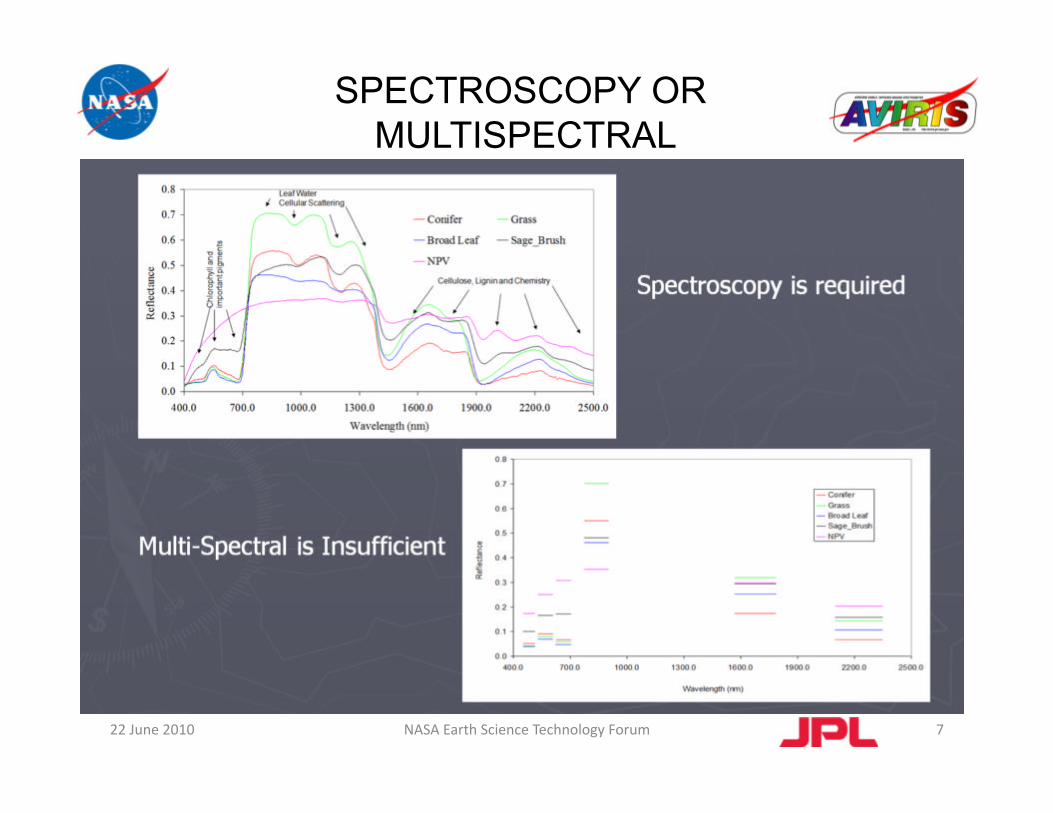
SPECTROSCOPY OR MULTISPECTRAL
7 22 June 2010 NASA Earth Science Technology Forum

JPL EXPERIENCE
• AIS
• AVIRIS
• NIMS, VIMS
• Hydice
• Hyperion
• [CRISM]
• MaRS
• MMM (M3)
• ARTEMIS
• PBTB and ISTB
Re@red in AVIRIS lab
Now flying in NASA ER‐2
VIMS orbi@ng Saturn
Re@red
Orbi@ng Earth
Orbi@ng Mars
Flying for DOD customer on various aircra`
Moon flight mission complete
Orbi@ng the Earth
Ongoing laboratory test bed ac@vi@es
[ ] = minimal JPL involvement, but important lessons learned.
RED = sensor no longer operating.
22 June 2010 8 NASA Earth Science Technology Forum

AVIRIS “CLASSIC” SCIENCE MEASUREMENTS
Spectral Range 380 to 2500 nm Sampling 10 nm Response 10 nm
Radiometric Range 0 to Max Lambertian Sampling 14 bit Calibration +/- 1nm Signal-to-Noise ratio >1000 @ 600 nm >400 @ 2200 nm
Spatial Field-of-View 34 degrees Instantaneous FOV 1 milliradian Spatial swath 2.5 to 11 km @ alt (4 to 20 km) Spatial resolution 4 to 20 m @ alt (4 to 20 km)
Uniformity Spectral-Cross-Track >95% Uniform Spectral-IFOV >95% Uniform
22 June 2010 9 NASA Earth Science Technology Forum

AVIRIS-NG KEY SCIENCE REQUIREMENTS
22 June 2010 10 NASA Earth Science Technology Forum
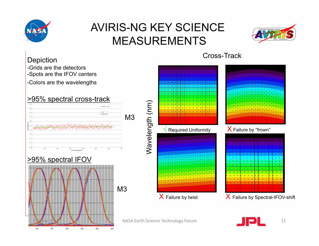
√ Required Uniformity X Failure by “frown”
X Failure by twist X Failure by Spectral-IFOV-shift
Cross-Track Depiction -Grids are the detectors -Spots are the IFOV centers -Colors are the wavelengths
>95% spectral cross-track
>95% spectral IFOV
M3
AVIRIS-NG KEY SCIENCE MEASUREMENTS
Wav
elen
gth
(nm
)
M3
22 June 2010 11 NASA Earth Science Technology Forum

RESEARCH AND APPLICATIONS
• Atmosphere: water vapor, clouds properties, aerosols, absorbing gases …
• Ecology: chlorophyll, leaf water, lignin, cellulose, pigments, structure, nonphotosynthetic constituents …
• Geology and soils: mineralogy, soil type …
• Coastal and Inland waters: chlorophyll, plankton, dissolved organics, sediments, bottom composition, bathymetry …
• Snow and Ice Hydrology: snow cover fraction, grainsize, impurities, melting …
• Biomass Burning: subpixel temperatures and extent, smoke, combustion products …
• Environmental hazards: contaminants directly and indirectly, geological substrate …
• Calibration: aircraft and satellite sensors, sensor simulation, standard validation …
• Modeling: radiative transfer model validation and constraint …
• Commercial: mineral exploration, agriculture and forest status …
• Algorithms: autonomous atmospheric correction, advance spectra derivation …
• Other: human infrastructure ...
22 June 2010 12 NASA Earth Science Technology Forum

Photo by Paul Gardner
AVIRIS “CLASSIC” 100S OF FLIGHTS OVER 20 YEARS
22 June 2010 13 NASA Earth Science Technology Forum

22 June 2010 14 NASA Earth Science Technology Forum

a thoughtful, dedicated JPL team 22 June 2010 15 NASA Earth Science Technology Forum

VEGETATION FUNCTIONAL TYPE ANALYSIS, SANTA BARBARA, CA MESMA Species Type 90% accurate
Species Fractional Cover
Dar Roberts, et al, UCSB
16 22 June 2010 NASA Earth Science Technology Forum

CERRO GRANDE FIRE SEVERITY, LOS ALAMOS, NM, RAY KOKALY
17 22 June 2010 NASA Earth Science Technology Forum

Surface mineralogy Cuprite, NV
Remote Measurement via Spectral Fitting
22 June 2010 18 NASA Earth Science Technology Forum

19
SURFACE COMPOSITIONAL DERIVED WITH IMAGING SPECTROMETER MEASUREMENTS
(AVIRIS)
22 June 2010 NASA Earth Science Technology Forum
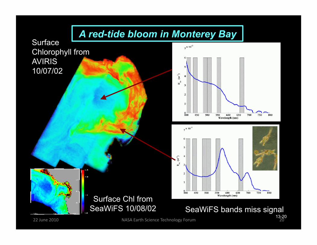
A red-tide bloom in Monterey Bay Surface Chlorophyll from AVIRIS 10/07/02
Surface Chl from SeaWiFS 10/08/02 SeaWiFS bands miss signal
13-20 22 June 2010 20 NASA Earth Science Technology Forum

SIMI VALLEY,CA WILD FIRE
22 June 2010 21
NASA Earth Science Technology Forum

Mount Rainier derived three phases of water (Vapor: blue, Liquid: green, Ice: red) in melting snow environment
22 22 June 2010 NASA Earth Science Technology Forum

23
NEXT GENERATION AIRBORNE VISIBLE / INFRARED IMAGING SPECTROMETER (AVIRIS-NG)
AMERICAN RECOVERY AND REINVESTMENT ACT (ARRA)
Design and build follow-on to AVIRIS (higher sampling, high signal-to-noise) • Task Budget: $5M • Task Schedule: September 1, 2009 – October 1, 2010
22 June 2010 NASA Earth Science Technology Forum

Spectral Range 380 to 2500 nm Sampling 10 nm Response 10 nm
Radiometric Range 0 to Max Lambertian Sampling 14 bit Calibration +/- 1 nm Signal-to-Noise ratio >1000 @ 600 nm >400 @ 2200 nm
Spatial Field-of-View 34 degrees Instantaneous FOV 1 milliradian Spatial swath 2.5 to 11 km @ alt (4 to 20 km) Spatial resolution 4 to 20 m @ alt (4 to 20 km)
Uniformity Spectral-Cross-Track >95% Uniform Spectral-IFOV >95% Uniform
22 June 2010 24 NASA Earth Science Technology Forum
AVIRIS NEXT GENERATION SCIENCE MEASUREMENTS
5 nm 5-7 nm
+/- 0.1 nm >2000 >1000
22 June 2010
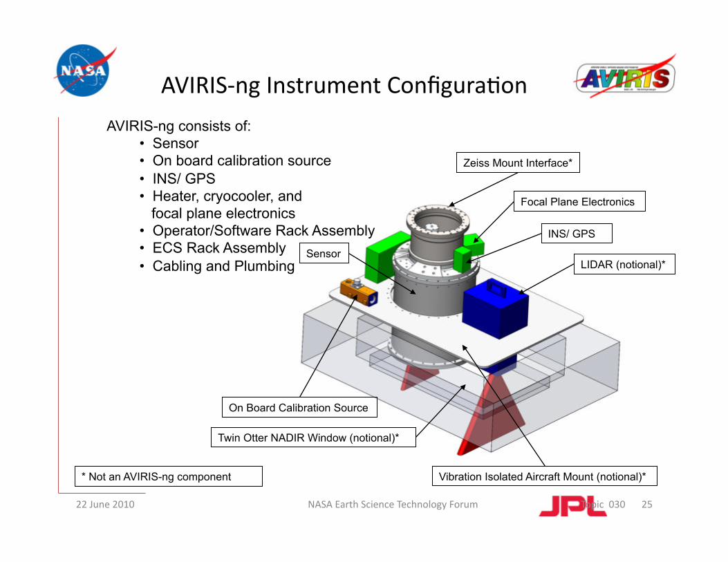
AVIRIS-ng consists of: • Sensor • On board calibration source • INS/ GPS • Heater, cryocooler, and focal plane electronics • Operator/Software Rack Assembly • ECS Rack Assembly • Cabling and Plumbing
NASA Earth Science Technology Forum Topic 030
AVIRIS‐ng Instrument Configura@on
Sensor
Focal Plane Electronics
INS/ GPS
LIDAR (notional)*
* Not an AVIRIS-ng component
On Board Calibration Source
Twin Otter NADIR Window (notional)*
Vibration Isolated Aircraft Mount (notional)*
Zeiss Mount Interface*
25

+ZNISDVU
+YNISDVU +XNISDVU Origin at Slit
Origin at Slit
20.5 Deg
+YNISDVU
+ZNISDVU
+XNISDVU/SENSOR
+ZSENSOR
+YSENSOR
NASA Earth Science Technology Forum Topic 070
AVIRIS‐NG COORDINATES
22 June 2010 26

22 June 2010 NASA Earth Science Technology Forum Topic 030
Sensor Configuration
Cryocoolers (2X)
Spectrometer
Thermal Shields, Passive (2X)
Thermal Shield, Active Thermal Control Kinematic Struts, Active
Thermal Control
Vacuum Chamber
Telescope
Window
27

22 June 2010 28
• Pushbroom imager collects image “lines”
• Image lines are collected into data “cubes”. Typical cubes are taken over 20 minute runs.
• Image “swath” is the width of the data cube. Swath dimensions are a function of altitude.
• Cube data are geo-rectified using GPS/INS data to correct for platform motion
• Cubes are radiometrically calibrated against a stable on-board source before and/or after each run
• The NISDVU is designed to be easily integrated with LIDAR
Geo-rectified Data
Raw Spatial Data
The NISDVU Data Cube
System Operation
NASA Earth Science Technology Forum

NASA Earth Science Technology Forum Topic 050
Instrument Op@cal Architecture
OFFNER SPECTROMETER, 2 MIRROR ANASTIGMAT HIGH-THROUGHPUT TELESCOPE SIMPLE SYSTEM: 4 MIRRORS, 1 GRATING, 1 DETECTOR
Exterior Window (F)
Baffle (F) TM1 (F)
TM2 (F) Slit (Ax,y,z)
Baffle (F)
Baffle (F)
SM1 (F)
SM2 (Ax,y,z,clocking)
SM3 (Ax,y,z) Baffle (F)
Baffle (Ax,y)
FPA (Ax,y,z,tip.tilt,clocking)
Spectrometer Assy (F) Telescope Assy (Az)
Baffle (F)
Baffle (F)
Baffle (F)
Baffle (F)
+YSENSOR
+ZSENSOR +XSENSOR
(Origin at Slit)
22 June 2010 29

ASSEMBLED TESTBED TELESCOPE
Achieved 1.1 wave p-v wavefront error over entire aperture and field with minutes of assembly time.
Notice non-circular pupil shape.
Post-polished aluminum mirrors produced by Axsys.
Previous Axsys mirrors fail mid-frequency specification by a factor of 2-3, impact acceptable (see risks and mitigations later).
22 June 2010 30 NASA Earth Science Technology Forum

SPECTROMETER PERFORMANCE
(X- AND Y- ENCLOSED ENERGY IN PIXEL) (ACCOUNTS FOR APODIZATION)
400 nm
2500 nm
22 June 2010 31 NASA Earth Science Technology Forum

ON-BOARD CALIBRATOR • Maintain absolute radiometric calibration within 95% across all spectral channels
within the FOV
• As designed will also – Allow image specific flat fielding to control small radiometric variability and deviations
– Allow trend monitoring to detect performance issues early
• To meet the requirements we will use a refinement of the on-board calibrator source currently flying and meeting these requirements in AVIRIS and MaRS.
22 June 2010 NASA Earth Science Technology Forum 32

OBC TARGET
• OBC target in front of slit
22 June 2010 NASA Earth Science Technology Forum 33
Fiber Illumination
Target
Slit

• Mature OBC approach with extensive heritage • We have tested the use of the OBC target at the slit entrance • OBC now in testing for installation into AVIRIS-ng
Pupil Target
Grating
CCD
TESTBED OBC TARGET TESTING
22 June 2010 34 NASA Earth Science Technology Forum

INSTRUMENT CRYOVACUUM ARCHITECTURE
cryocoolers, power supplies, and drive electronics
recirculating fluid chiller removes heat from cryocoolers
temperature monitoring and control maintains FPA temperature stability and optical alignment (multiple locations on instrument)
vacuum-ion pump and gauge decision on use of the ion pump is pending system performance evaluation
cryo wiring harness is fabricated in-house; not shown 22 June 2010 35 NASA Earth Science Technology Forum

cryocooler cold ends ~110 K steady-state Both coolers run for cooldown, then one switches off. (Straps to inner shield and spectrometer are not shown)
Two “floating” and one actively-cooled radiation shields reduce heat input to spectrometer: 1st shield ~288 K, floating 2nd shield ~235 K, floating actively-cooled shield ~125 K, controlled
Thermally-isolating kinematic struts support instrument from warm outer vacuum shell (318 K maximum environmental temperature)
Spectrometer and telescope temperature are actively controlled to <50 mK variation
FPA is cooled to <140 K and actively controlled. (Dedicated high-conductance strap to cold sink not shown.)
CRYOVACUUM SUBSYSTEM OPERATIONAL CONDITIONS
Vacuum enclosure carries window, cryocoolers, all electrical and vacuum feedthroughs, all mechanical loads
22 June 2010 36 NASA Earth Science Technology Forum

DESIGN /FABRICATION STATUS
• Design complete • Mechanical and Cyro-vacuum parts
now in fabrication • 45% of parts now received, complete in
August 2010
22 June 2010 NASA Earth Science Technology Forum 37

I&T STATUS
22 June 2010 NASA Earth Science Technology Forum 38
• Facility Ready • Personnel trained • GSE design complete – now in build • Plans, procedures and storyboards in review • “Pre” I&T now underway • I&T begins July 2010
• Focal Plane Interface Electronics • only 1 analog board (only 1 focal plane assembly) • FPGA programming has been modified
• 1 Focal Plane Assembly (no multiplexing) • uses MaRS 14-bit capability (MaRS only used 12 bits) • MaRS pedestal shift problem identified and corrected • GPS time tag incorporated (requirement) • 1st pixel clock extension incorporated (for warmer FPA operation) • line buffers enable non-interleaved data output • larger FPGA (pin-compatible and EEPROM compatible)
• Camera Link Data Path (to next-generation frame grabber card) • OBC and control electronics • C-MIGITS III INS/GPS
ELECTRONICS DESIGN‐ MARS HERITAGE
39 NASA Earth Science Technology Forum 22 June 2010

FOCAL PLANE ARRAY
• Well-known Teledyne TCM6604A
• Capacitive transimpedance amplifier
• Snapshot imaging
• 4 video outputs, 1 ref output (unused)
• 4 clocks, 7 bias voltages
• Power dissipation: ~ 60mW
• Read noise: 120 e- [rms]
• Amplifier glow: ~ 100 e-/sec
• Recent understanding of a phenomenon affecting blue-end QE stability is yielding processing steps for mitigation
• Devices are straightforward to fabricate using current vendor processes
• Custom JPL drive electronics exist and work extremely well with this FPA
TELEDYNE PROPRIETARY INFORMATION
40 NASA Earth Science Technology Forum 22 June 2010

I&T FLOW DIAGRAM
22 June 2010 41 NASA Earth Science Technology Forum

• Purpose – Story board for the integra@on process
• Descrip@on – Provide hardware informa@on (adhesives, fasteners, parts
lists, etc.) to aid during integra@on – Provide installa@on notes – Record bolt torque values – Document torque wrench informa@on
– Collect and document thoughts and notes before, during and a`er integra@on
• Status • Done
MECHANICAL/THERMAL/OPTICAL INTEGRATION PROCEDURE
22 June 2010 42 NASA Earth Science Technology Forum

WARM ALIGNMENT STORYBOARD
Note: Slides above represent only a portion of the full document
Descrip=on: A step‐by‐step visual guide to the warm alignment process, including GSE needed and verifica@on steps
Status: Done Successful peer review 06/09/10
22 June 2010 43 NASA Earth Science Technology Forum
SUMMARY • The science enabled by a high uniformity and high signal-to-noise ratio
imaging spectroscopy is well established – AVIRIS referenced in > 600 refereed journal articles
• We understand the key measurement characteristics that are needed
• We have developed the right set of requirements flowing from the science
• Throughout the AVIRIS-ng effort, these science traced requirements will be tracked, balanced, and reported to assure the instruments are ready for the next generation science
• The design is complete and being manufactured
• AVIRIS-ng is being built and will be integrated this summer
44 22 June 2010 NASA Earth Science Technology Forum