ilba log building standards - section a 2000 · pdf filethese are minimum standards for...
TRANSCRIPT
55ILBA Log Buiding Standards
ILBA Log Building Standards - Section A
2000 LOG BUILDING STANDARDSSection A: for Residential, Handcrafted, Interlocking, Scribe-fit Construction
© International Log Builders' Association
The Association, founded in 1974, is a world-wide organization devoted to furthering the craft of log con-struction. The Canadian Log Builders’ Association, International is a registered non-profit Society in Canadaand the American Log Builders’ Association is registered as non-profit in the United States. The Associationwrites and distributes educational material on log construction to individuals, institutions, and industry. Theorganization is dedicated to the advancement of Log Builders and to the promotion of the highest standards oftheir trade.
It is the responsibility of every builder to understand and to conform to the best practices of thetrade. These are minimum Standards for residential, handcrafted, interlocking, scribe fit log construction. Theyare revised by the Building Standards Committee. Changes to this edition were made in January 2000.
The Association has endeavored to prepare this publication based on the best information availableto the Association. While it is believed to be accurate, this information should not be used or relied upon forany specific application without competent professional examination and verification of its accuracy, suitability,and applicability. The publication of the material herein is not intended as a representation or warranty on thepart of the Canadian Log Builders Association, International, American Log Builders’ Association, its affiliates,or any person named herein that this information is suitable for any general or particular use or of freedomfrom infringement of any patent or patents. Anyone making use of this information assumes all liability arisingfrom such use.
These Standards are founded on performance principles that allow the use of new materials and newconstruction systems. Anyone may propose amendments to these standards. These standards are not intend-ed to prevent the use of any material or method of construction not specifically prescribed by these standards,provided the proposed action is satisfactory and complies with the intent of the provisions of these standardsand that the material, method or work offered is, for the purposes intended, at least the equivalent of that pre-scribed in these standards in suitability, strength, effectiveness, fire resistance, durability, safety and sanitation.
These standards are copyright, and may not be reprinted, copied, or in any way duplicated, withoutthe written permission of the President or Secretary of the Association.
For further information, or additional copies of these standards, please contact:
The International Log Builders’ Associationformerly known as
Canadian Log Builders’ Association, International American Log Builders’ Association
PO Box 775Lumby, BC Canada V0E 2G0
Phone (250) 547-8776FAX (250) 547-8775
(800) 532-2900
56 ILBA Log Buiding Standards
ILBA Log Building Standards - Section A
Preface 1. In these Standards the word “shall” means
mandatory, and the word “may” means dis-cretionary.
2. The 2000 Log Building Standards are comprisedof both the Standards and the Commentary.
Section 1 FOUNDATIONSShall conform to applicable building codes and
accepted engineering practice.
Section 2 LOG WALLS2.A. Log Specifications2.A.1. The minimum diameter of wall logs shall be
20 centimeters (8 inches).2.A.2. Green or dry logs may be used for con-
struction.2.A.3. Logs shall have all bark removed, and shall
be of sound wood.Table 2.A
2.A.4. Spiral Grain:The following restrictions apply to the use ofgreen logs. (Refer to Table 2.A for definitionsof spiral grain categories):a. Left-hand severe spiral logs shall be usedas wall logs only as cut-in-half sill logs.However, left-hand severe spiral logs may beused as a whole-sill log if all four of the condi-tions listed below are met.b. Left-hand moderate spiral logs shall beused only in the lowest one-third (1/3) of thevertical height of a wall. However, left-handmoderate spiral logs may be used in the low-est one-half (1/2) of the vertical height of awall if all four of the conditions listed beloware met.c. Right-hand severe spiral logs shall be usedonly in the lowest one-quarter (1/4) of thevertical height of a wall. However, right-handsevere spiral logs may be used in the lowestone-third (1/3) of the vertical height of a wallif all four of the conditions listed below aremet:Conditions:1) the log has two or more corner notches,and2) the log is not spliced, and
Section 1 FOUNDATIONSLike all buildings the foundation of a log building must be of suf-
ficient design to support safely the loads imposed as deter-mined from the character of the soil. In addition to theloads imposed by gravity, the foundation is important inconnecting the building to the ground as it resists wind orseismic forces and accelerations. Therefore the connectionbetween the building and the foundation must also becapable of resisting the sliding, uplift and overturning asso-ciated with local wind and seismic conditions.
Section 2 LOG WALLS2.A. Log Specifications2.A.1. Logs smaller than 20 centimeters (8 inches) in diameter
are unsuited to residential construction.2.A.2. For the purposes of this Standard, “dry” means moisture
content equal to or less than 19%, and “green” meansmoisture content greater than 19%. Dry and green logshave different requirements for preventing sapstain, andhave different shrinkage and structural properties thatmust be appropriately accounted for in design and con-struction.
2.A.3. Leaving the bark on logs promotes insect attack andmakes scribe-fitting difficult. Eventually, the bark will falloff by itself, though by that time the wood has usuallybeen degraded by fungus or insects, or both.
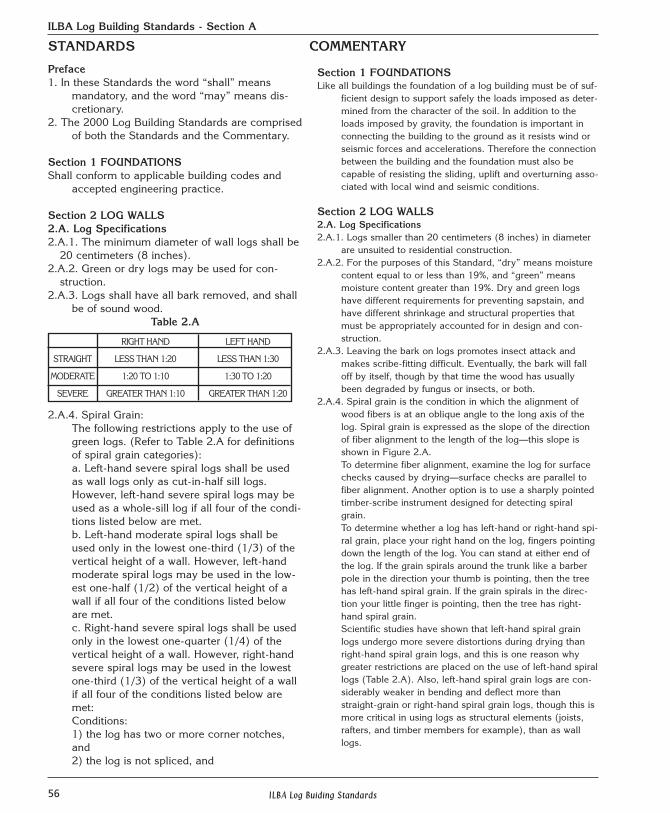
2.A.4. Spiral grain is the condition in which the alignment ofwood fibers is at an oblique angle to the long axis of thelog. Spiral grain is expressed as the slope of the directionof fiber alignment to the length of the log—this slope isshown in Figure 2.A. To determine fiber alignment, examine the log for surfacechecks caused by drying—surface checks are parallel tofiber alignment. Another option is to use a sharply pointedtimber-scribe instrument designed for detecting spiralgrain.To determine whether a log has left-hand or right-hand spi-ral grain, place your right hand on the log, fingers pointingdown the length of the log. You can stand at either end ofthe log. If the grain spirals around the trunk like a barberpole in the direction your thumb is pointing, then the treehas left-hand spiral grain. If the grain spirals in the direc-tion your little finger is pointing, then the tree has right-hand spiral grain.Scientific studies have shown that left-hand spiral grainlogs undergo more severe distortions during drying thanright-hand spiral grain logs, and this is one reason whygreater restrictions are placed on the use of left-hand spirallogs (Table 2.A). Also, left-hand spiral grain logs are con-siderably weaker in bending and deflect more thanstraight-grain or right-hand spiral grain logs, though this ismore critical in using logs as structural elements (joists,rafters, and timber members for example), than as walllogs.
STANDARDS COMMENTARY
RIGHT HAND LEFT HAND
STRAIGHT LESS THAN 1:20 LESS THAN 1:30
MODERATE 1:20 TO 1:10 1:30 TO 1:20
SEVERE GREATER THAN 1:10 GREATER THAN 1:20
57ILBA Log Buiding Standards
ILBA Log Building Standards - Section A
3) no more than two-thirds (2/3) of the log’sdiameter is cut or removed at any opening,and4) if any portion of this log extends beyond anotch in a wall, then the length of this exten-sion is not more than 4'-0", measured fromthe center of the closest notch to the end cutof this log.d. Right-hand moderate spiral grain logs maybe used as a wall log at any location in thebuilding, except shall not be used in the topround of logs.e. Straight grain logs may be used in anylocation.f. The top round of logs shall be straight grainonly; see also Section 2.I.4.
Figure 2.A2.B. Log Walls Shall be constructed of logs laid in horizontal
courses, scribe-fit one to another, with inter-locking notches at the corners.
2.C. Sill Logs 2.C.1. Shall be not less than 20 centimeters (8
inches) in diameter.2.C.2. Shall be flattened on their bottom side for
their entire bearing length to a width of notless than 10.2 centimeters (4 inches).
2.C.3. Shall not be in direct contact with masonry.2.C.4. Shall be set on a vapor, weather, and air
barrier.2.C.5. Shall have a drip cut or flashing that directs
water away from the underside of the sill log. 2.C.6. Shall be anchored to resist applicable wind
and seismic loads.2.C.7. Shall be a minimum of 30.5 centimeters (12
inches) above grade
2.D. Long Grooves2.D.1. Logs in walls shall have a continuous
scribe-fit long groove along the length of eachlog. A long groove is required wherever a logwall separates unheated from heated space,or heated space from the exterior of the building.
Section 2.A.4 describes the ways builders can help hold spirallogs in place in the walls. Logs that are more likely to twistare used lower in the wall, where there is more weight onthem. For spiral types (a), (b), and (c) the standards canbe relaxed somewhat if you use four additional methods torestrict twisting. A log that has at least two full notches ismore likely to stay put than a log with one notch (condi-tion #1). A full notch is more stabilizing than a splice notch(condition #2). A spiral log with a window sill cut-out ismore likely to behave like it is one piece if no more thantwo-thirds of a log’s diameter is removed (condition #3).And, when a wall log extends beyond a notch more than 4'to a door or window opening, this portion of the log ismore likely to twist (condition #4).
These tables refer to green logs, slope of grain willchange as logs dry.
2.B. Log WallsThese Standards do not apply to walls constructed of vertical
logs, logs that are not fully scribe-fit to one another, Pieceen Piece, or to manufactured log home kits. For more onnotches see Section 4.
2.C. Sill Logs Sill Logs are the bottom logs of the building, the first logs above
the foundation in each wall.2.C.1. See also the log specifications in Section 2.A.2.C.2. A continuous sawn flat provides bearing area and stability
for sill logs. 2.C.3. Untreated wood should not be in direct contact with
masonry because of the likelihood of decay.2.C.4. Caulks, sealants and gaskets can provide vapor, air and
water barriers.2.C.5. To avoid decay, it is important that rainwater be directed
away from under the sill logs.2.C.6. The amount and kind of anchoring depends upon local
conditions and codes. In areas of extreme wind and seis-mic load conditions, continuous through-bolting the fullheight of the log wall to the foundation can be an effectivetechnique.
2.C.7. Sill logs can be prone to decay if they are too close tograde and rainwater and soil splashes on them.
2.D. Long Grooves.Also known as “lateral,” “lateral groove,” “cope,” “Swedish
cope,” and “long notch.” The long groove is a notch cutinto a log to fit two logs together along their lengthbetween intersecting corner notches.
2.D.1. The long groove must be continuous between notches oropenings, such as for doors. Other styles of log construc-tion do not have a long groove, or have a groove that isnot continuous—the gaps between logs are then filled witha chinking material. Scribe-fit logwork, in contrast, has acontinuous long groove, and no chinking is requiredbecause there are no gaps to fill. The interior edges of thelong groove are often sealed with a gasket material, and itsinterior is commonly insulated.
STANDARDS COMMENTARY
58 ILBA Log Buiding Standards
ILBA Log Building Standards - Section A
Figure 2.D
2.D.2. Long grooves shall be self-draining or shallhave gaskets, and in all cases shall restrictwater, air, and insect infiltration.
2.D.3. The minimum width of the long groove shallbe 6.3 centimeters (2.5 inches) and this mini-mum width shall extend for no more than30.5 centimeters (12 inches) in continuouslength. At all times, however, the long grooveshall conceal and protect through-bolts, pins,dowels, kerfs, electrical holes, and the like,and shall be wide enough to restrict weatherand insect infiltration.
2.D.4. The maximum width of the long grooveshall be three-eighths (3/8) of the log diame-ter at each point along the log. In cases ofextremely irregular log contours the widthmay be increased to one-half (1/2) of the logdiameter, but this increased allowance shallextend for no more than 46 centimeters (18inches) in continuous length.
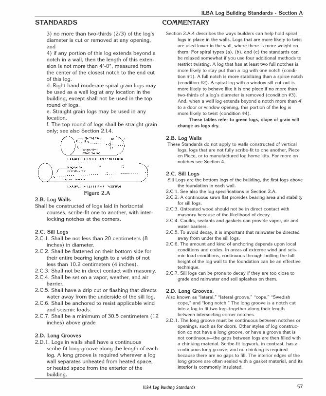
2.D.5. The long groove may have the followingcross-sectional profiles: rectangular, shallowcove, “W” shaped, or double-scribed.
2.D.6. The depth to which the groove is cut shallbe no more than one-quarter (1/4) the diam-eter of the log (see also Section 2.J.2).
2.E. Log Extensions2.E.1. The maximum length of log extensions shall
be based on weather protection criteriadescribed in Section 7.D.
2.E.2. The minimum length of log extensions shallbe 23 centimeters (9 inches) measured fromthe edge of the notch to the end of the logoverhang. This standard applies to both interi-or and exterior log extensions. Dovetail cornernotches are exempt from this requirement.
2.E.3. Exterior log extensions shall not have atight fit to the log extensions below. SeeFigure 3.B.3
2.D.2. Some profiles are not self-draining, that is they couldtrap water, and so promote decay. Such long groovesshall have gaskets to restrict water from getting into thegroove. Being visibly tight is not sufficient to restrict air orwater infiltration.
2.D.3. Narrow long grooves are difficult to seal from the weath-er. The groove must always be wide enough to restrictweather infiltration into kerfs, electrical holes, and thelike.
2.D.4. Wide long grooves remove so much wood that the log isunduly weakened and may check only on the bottom ofthe log, which is not desired. (See also Section 2.J.)
2.D.5. There are many shapes, or cross-sectional profiles, forlong grooves. Figure 2.D. illustrates some of these.Desired traits are: sharp and strong edges along the scribeline; a reasonable minimum amount of wood removedfrom the groove so that the groove touches the log belowonly along its scribed edges with no internal “hang-ups;”and a reasonable assurance that the log will check on itstop (that is, in the kerf) as it dries. (See Section 2.J formore on kerfs.)
2.D.6. Deep long grooves are not necessary, and can weaken alog. Note that at least one-half of the diameter of the logmust remain intact after both the kerf and long groove arecut (Section 2.J.2).
2.E. Log ExtensionsAlso known as “flyways” or “log overhangs,” are the shortpart of the log that extends past a notched corner.
2.E.1. Overly long log extensions can be prone to decay unlessadequately protected by roof overhangs or other means.
2.E.2. Overly short log extensions can be prone to having woodsplit off, severely weakening the notch and the corner.Interior log extensions are those that project inside abuilding, and exterior log extensions extend towards theoutside of a building. The stability of a dovetail cornerdoes not depend upon log extensions, and is not suscepti-ble to having wood split off, and so is exempt from anyminimum length requirement.
2.E.3. The end-grain of exterior log extensions can take onmoisture seasonally, shrinking or swelling more than therest of the log. If the long grooves of extensions fit tightly,then during periods of high moisture the tight fit of thelong grooves along the rest of the log could be compro-mised. This has, in fact, been observed—tight longgrooves in the log extensions and gaps in the grooveseverywhere else.
Since log extensions are not kerfed (Section 2.J.7),it is probable that log extensions will check on their bot-toms—from their long grooves towards the center of thelog. When logs check in this location, internal hang-upsare common. To avoid this, the grooves of exterior logextensions should have enough wood removed to avoidhang-ups after checking and slumping. See Figure 3.B.3.
STANDARDS COMMENTARY
59ILBA Log Buiding Standards
ILBA Log Building Standards - Section A
2.E.4. Where a log extension acts as a support for a structuralmember this extension and the structurally supporting logsbelow shall be exempt from the requirement in 2.E.3 (seealso Section 7.J).
2.F. Distance Between Corners2.F.1. When using logs with a diameter less than 30.5 centimeters
(12 inches) the distance between intersecting log walls withcorner notches shall be no more than 7.3 meters (24 feet).When using logs with a minimum diameter of 30.5 centime-ters (12 inches) the distance between corner notches shall beno more than 9.75 meters (32 feet). Log walls with spans inexcess of these distances shall have reinforcement such aswood keys, dowels, smooth-shaft steel, through-bolts, lagscrews, steel bar, or log stub-walls. All such reinforcementshall allow for settling (see Section 6).
2.F.2. Log walls with openings cut for doors, windows and pas-sageways may require additional bracing. The loads on a logwall, and the openings cut into a log wall, will affect its struc-tural performance and may require structural analysis.
2.G. Joining Logs Lengthwise2.G.1. Spliced logs shall be secured to each other with bolts or
other fasteners, and to adjoining courses of logs above andbelow with steel pins, wooden dowels, lag bolts or through-bolts in a manner that preserves the structural integrity of thewall.
2.G.2. When more than half of the logs in a corner are spliced,then engineering analysis shall be required.
2.G.3. The notch and long-groove shall at all times completelyhide a splice and its fasteners, and help protect splicesagainst weather and insect infiltration.
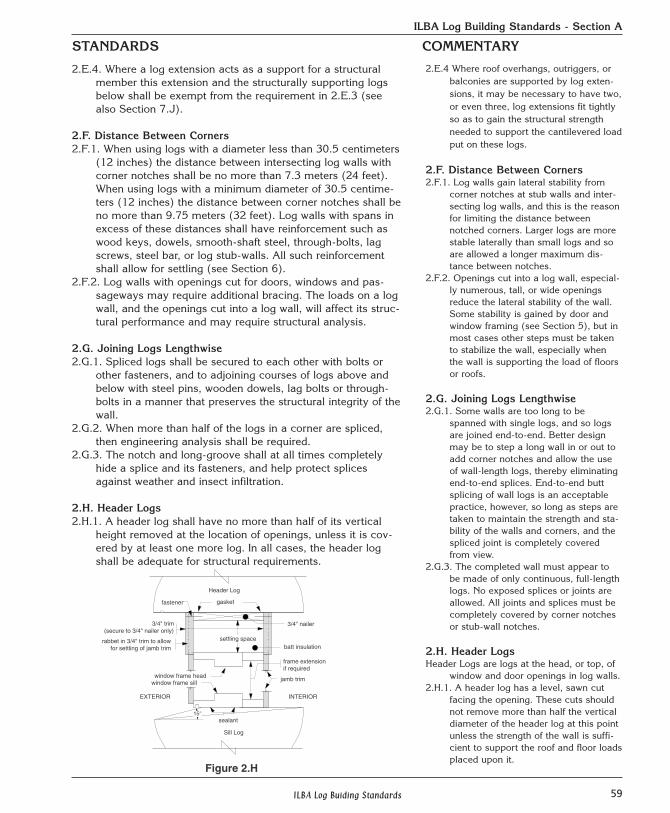
2.H. Header Logs2.H.1. A header log shall have no more than half of its vertical
height removed at the location of openings, unless it is cov-ered by at least one more log. In all cases, the header logshall be adequate for structural requirements.
2.E.4 Where roof overhangs, outriggers, orbalconies are supported by log exten-sions, it may be necessary to have two,or even three, log extensions fit tightlyso as to gain the structural strengthneeded to support the cantilevered loadput on these logs.
2.F. Distance Between Corners2.F.1. Log walls gain lateral stability from
corner notches at stub walls and inter-secting log walls, and this is the reasonfor limiting the distance betweennotched corners. Larger logs are morestable laterally than small logs and soare allowed a longer maximum dis-tance between notches.
2.F.2. Openings cut into a log wall, especial-ly numerous, tall, or wide openingsreduce the lateral stability of the wall.Some stability is gained by door andwindow framing (see Section 5), but inmost cases other steps must be takento stabilize the wall, especially whenthe wall is supporting the load of floorsor roofs.
2.G. Joining Logs Lengthwise2.G.1. Some walls are too long to be
spanned with single logs, and so logsare joined end-to-end. Better designmay be to step a long wall in or out toadd corner notches and allow the useof wall-length logs, thereby eliminatingend-to-end splices. End-to-end buttsplicing of wall logs is an acceptablepractice, however, so long as steps aretaken to maintain the strength and sta-bility of the walls and corners, and thespliced joint is completely coveredfrom view.
2.G.3. The completed wall must appear tobe made of only continuous, full-lengthlogs. No exposed splices or joints areallowed. All joints and splices must becompletely covered by corner notchesor stub-wall notches.
2.H. Header Logs Header Logs are logs at the head, or top, of
window and door openings in log walls.2.H.1. A header log has a level, sawn cut
facing the opening. These cuts shouldnot remove more than half the verticaldiameter of the header log at this pointunless the strength of the wall is suffi-cient to support the roof and floor loadsplaced upon it.
STANDARDS COMMENTARY
gasket
15°
3/4" nailer3/4" trim(secure to 3/4" nailer only)
window frame headwindow frame sill
Header Log
settling space
frame extensionif required
jamb trim
rabbet in 3/4" trim to allowfor settling of jamb trim
sealant
EXTERIOR INTERIOR
batt insulation
Sill Log
fastener
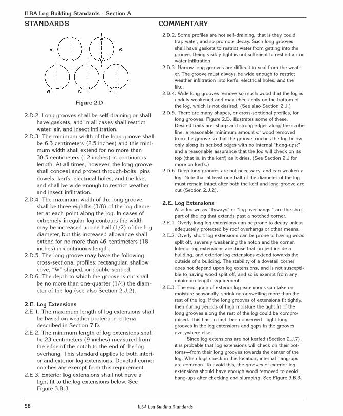
Figure 2.H
60 ILBA Log Buiding Standards
ILBA Log Building Standards - Section A
2.H.2. Openings in header logs shall be cutso as to completely cover door andwindow head jambs and exterior trim inorder to restrict water infiltration.
2.I. Plate Logs2.I.1. Wall plate logs shall be notched, drift-
ed, pegged, lag-bolted or through-bolt-ed to the log below to prevent move-ment caused by drying stress and roofthrust. Wall plate logs shall be attachedwith lag or through-bolts to one ormore rounds of logs below the plate logso as to resist the uplift forces associat-ed with local wind and seismic condi-tions.
2.I.2. Where conventional framing meets aplate log this intersection shall have anexpandable gasket to accommodateanticipated shrinkage of the log plateand to restrict weather and insect infil-tration.
2.I.3. The ceiling vapor retarder, whererequired by local code, shall be perma-nently sealed to the plate log with caulkor sealant.
2.I.4. Plate logs shall be straight grainedwood (see Section 2.A.4.f).
2.J. Kerfing2.J.1. When building with green logs, a lon-
gitudinal kerf shall be cut on the top ofeach wall log.
2.J.2. The depth of the kerf shall be at leastone-quarter (1/4) of the diameter of thelog, and shall be no deeper than one-half (1/2) the diameter. In no case shallmore than one-half (1/2) the diameterof the log be removed by the kerf andlong groove combined.
2.J.3. Kerfs shall at all times be protectedfrom weather by being fully covered bythe long groove of the log above, or bya notch.
2.J.4. The kerf shall be continuous, or shallstart 15 centimeters (6 inches) fromthe edge of all notches, and shall becontinuous between the notches,except that kerfs need not extend intoopenings in log walls, or at the ends oflog extensions, where they would beseen.
2.H.2. Figure 2.H.1 illustrates one way to install settling boards andavoid water infiltration.
2.I. Plate Logs Plate Logs are the top logs on each wall. The roof framing rests on the
plate logs.2.I.1. Wall plate logs are prone to twisting and shifting and need extra steps
to keep them in place. Square notches and lock notches can providerestraint, as can any number of methods using bolts, threaded rod,and pegs. The number, type, size and spacing of mechanical fasten-ers used for this purpose must be determined by accepted engineer-ing practice. Continuous gable end plate logs are very effective atresisting roof thrust, and so are recommended when it is necessaryto counteract these forces. When continuous gable end plate logs arenot used, or are not used in a manner that will resist roof thrust, thisforce must be restrained or eliminated by other methods.Roof uplift caused by wind, for example, can be counteracted bylocking together the top rounds of each wall. Smooth pins such asdowels, smooth shaft steel, and wooden pegs are not sufficient forpreventing uplift, and this is why lag bolts and through-bolts arespecifically mentioned.
2.I.2-3. A recent study of Minnesota log homes found the intersection ofroof framing and the plate log to be the source of considerable airinfiltration. Special steps are required to make this area weather-tight. Permanently sealing the vapor barrier to the plate log is anaccepted method of reducing air infiltration and retarding the migra-tion of water vapor. Stapling the vapor retarder to the plate log is, byitself, not sufficient.
2.J. Kerfing2.J.1. The kerf is usually, though not always, a cut made with a chainsaw.
Logs are known to check, or crack, in those places where wood hasbeen removed closest to the pith, (or the center) of the log. Kerfing istherefore an effective way to control the location of checks as greenlogs dry. Because dry logs already have seasoning checks, kerfing usually willnot change the location of checks, and therefore kerfing is notrequired for dry logs.
2.J.2. The kerf must be deep enough to promote checking. Note that eventhose long groove profiles that do not require kerfing (like the dou-ble-cut) are nevertheless required to be the depth of at least one-quarter of the diameter of the log at every point along the top of thelog. (See also Section 2.D.5.)After a log has both the kerf and the long groove cut, there must stillbe at least one-half of the diameter of the log remaining un-cut.Removing more than half the diameter of the log for kerf and groovecombined would weaken the log, and so should be avoided. The amount of wood removed by the kerf (or special long grooveprofile) must be between 1/4 and 1/2 of the log diameter (Section2.D.6). When the kerf is 1/4 of the diameter of the log deep, then thegroove must be no more than 1/4 of the log diameter deep (1/4 plus1/4 equals 1/2). When the kerf is 1/3 of the log diameter deep, thenthe groove must be no more than 1/6 of the log diameter deep (1/6plus 1/3 equals 1/2).
2.J.3. Because kerfs are not self-draining, that is, they can catch rainwaterand hold it, kerfs must always be protected by being fully covered bythe groove of the log above or by a notch (also see Section 2.D.3). Inpractical terms, this means that kerfs are never visible in a complet-ed wall.
STANDARDS COMMENTARY
61ILBA Log Buiding Standards
ILBA Log Building Standards - Section A
2.J.5. No kerf shall be required when the long-groove profile encour-ages checking on the top of wall logs as in Figure 2.D #2, aslong as the groove and kerf along the top of the log is at least1/4 of the diameter of the log.
2.J.6. No kerf shall be required on the top of the half-log sill logs.2.J.7. No kerf shall be cut in exterior log extensions.
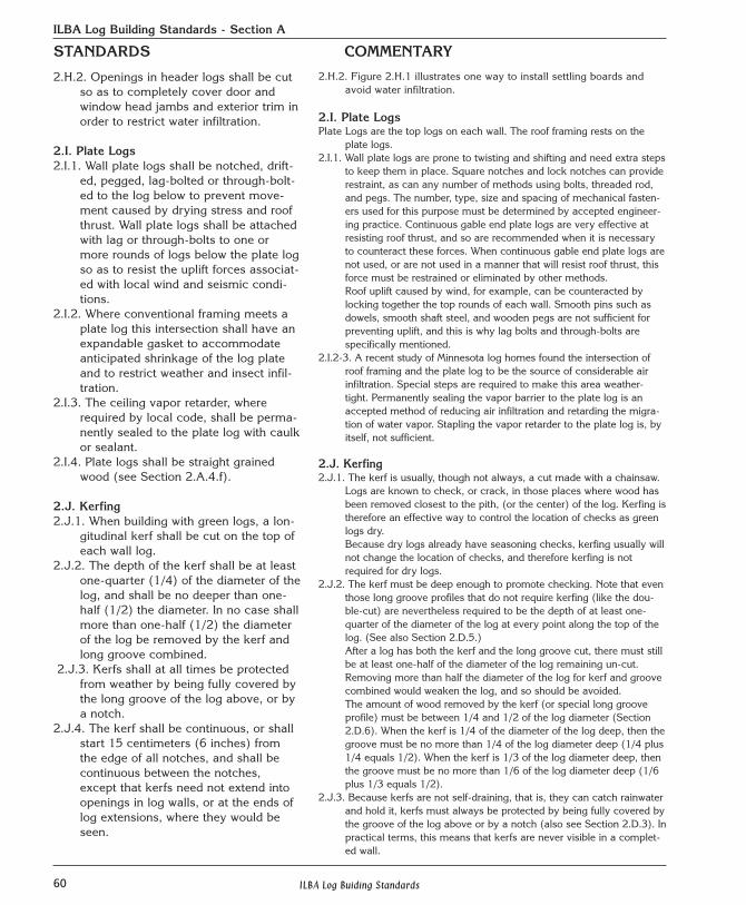
2.K. Log Wall-Frame Wall Intersections2.K.1. Log walls shall be cut as little as necessary when joined to
non-log partition walls.
2.K.2. Where wood is removed at the intersection of a log wall andframe wall, the log wall shall have 55% or more of its cross-sec-tional area remain intact and uncut. See Figure 2.K.2 below.
2.J.4. The kerf should run the full length ofthe top of every log, either stoppingbefore reaching a notch or continuingthrough a notch. In the case of open-ings or passageways cut in log wallsthat are not covered by jambs ordoors, the kerf would be unsightly—and in these areas the kerf need notextend all the way to the opening.
2.J.5. Some long-groove profiles encour-age checking without kerfing. Forexample, the long-groove known asdouble-cut or double-scribed (seeSection 2.D.5), removes a “V”shaped section from the top of everylog. Long-groove profiles that pro-mote checking on top of wall logs donot require a kerf, but they still mustcomply with Section 2.J.2.
2.J.6. Half-logs do not usually check, andso do not require a kerf.
2.J.7. No kerf should be cut on any logextensions outside the buildingbecause this upward-facing cut couldcatch and hold moisture from rainand promote decay. The longgrooves of exterior log extensionsshall not be tight-fitting (Section2.E.3), and so do not protect the kerffrom water, and this is why log exten-sions should not be kerfed.
2.K. Log Wall-Frame WallIntersections. It is common for some interior, non-bearing partition walls to be conven-tionally framed with studs. This sec-tion describes how stud walls andother non-log walls should beattached to logs walls.
2.K.1. It is common for a plumb groove,dado, or rabbet to be cut in the logwall and the first stud of the framewall to be attached to the log wall inthis groove. One problem is that tohave the frame wall completely sealagainst the log wall, the groove mustbe cut as deep as the narrowest longgroove, and this is often close to themid-point of the log wall. One way toavoid removing too much wood fromthe log wall, and unduly weakeningit, is shown in Figure 2.K.1, below.
2.K.2. Enough wood must be left in the logwall that it is not weakened by thedado. The dado must leave 55% ormore of the cross-sectional area atthis intersection uncut, Figure 2.K.1.
STANDARDS COMMENTARY
At least 55% of log cross section to remain intact at each notch.
frame wall
log wall
Plan View
FIGURE 2.K.1
CL
PLAN VIEW
SECTION VIEW
stud walllet into alog wall 55% or more of
cross section toremain intact.
55% or more ofcross section toremain intact.
stud walllet into alog wall
Figure 2.K.2
Plan View
62 ILBA Log Buiding Standards
ILBA Log Building Standards - Section A
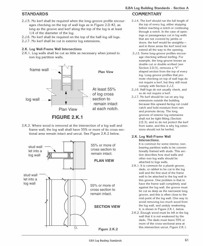
2.K.3. Where frame partition walls are notchedinto opposite sides of a log wall there shall bea minimum of 122 centimeters (4 feet)between the end of one notch and the begin-ning of the next notch on the opposite side ofthe log wall, or, if closer than 122 centimeters(4 feet), a minimum of one-third (1/3) of thewall cross-sectional area shall remain intactand uncut.
2.K.4. In no case shall cuts go past the centerlineor midpoint of the log wall.
2.K.5. Log wall-frame wall intersections mustallow for unrestricted settling of the log wall(see also Section 6).
2.L. Height of Log WallsLog walls taller than two stories, or 6.1 meters (20
feet) in height, shall require engineering analy-sis.
2.M. Bearing WallsBearing walls shall be designed and constructed to
structurally accommodate horizontal and ver-tical forces which are anticipated to act uponthe building.
2.N. Preservation of Log WallsWhere necessary, steps should be taken to restrict
the growth of mildew and fungus on logswhile the building is under construction.
Section 3 NOTCHES3.A. Self-Draining and Weather-RestrictingNotching
All forms of interlocking notches and joineryshall be self-draining and shall restrict weath-er and insect infiltration. Shrink-fit and com-pression-fit notches are recognized as achiev-ing these goals.
3.B. Notching Standards3.B.1. Notches shall have a concave profile across
the notch not less than 15 millimeters (9/16of an inch) and not more than 35 millimeters(1 and 3/8 inches).
2.K.3. Where two frame walls are closer than 122 centimeters (4feet) to each other, and on opposite sides of a log wall, thecross section of the log wall, after both dados are cut, musthave at least one-third of the wall area remain un-cut,Figure 2.K.3 Note, also, that Section 2.K.1 still applies—each single cut shall leave 55% or more of the cross sec-tional area at each intersection un-cut and intact. SeeFigure 2.K.3.
2.K.4. Cutting past the center of a log wall weakens it, and shouldbe avoided.
2.K.5. The first stud attached to the log wall must be fastened insuch a way as to allow the log wall to shrink and settle. Onecommon method is for lag screws to be attached to the logsthrough vertical slots cut in the stud, not just round holes.The lag screw and washer should be attached near the topof the slot, and allowed to slide down the slot as the log wallbehind shrinks in height.The frame wall must also allow a second floor, or the firstfloor ceiling, to lose elevation as the log walls shrink inheight. (See Section 6 for more on settling.)
2.L. Tall log walls Tall log walls should be evaluated for stability.
2.M. Bearing WallsBearing walls can be exterior or interior log walls. Roof andfloor loads are the most common loads to design for, butuplift and lateral loads from winds and seismic activity mayhave to be considered as well.
2.N. Preservation of Log WallsGreen logs, in particular, are prone to attack by mold,mildew, and fungus during construction. Dry wood will notdecay, and so good roof protection is very effective in pro-longing the life of log walls. During construction, and untilroof protection is complete, it may be advisable to use sap-stain and mold preventative chemicals or processes.Additionally the use of a sealant on all exposed end grainduring log storage, construction and after all work is com-pleted will slow the loss of moisture and reduce checking.
Section 3 NOTCHES3.A. Self-drainingSelf-draining means that notch surfaces slope in a way that
restrict water from getting into areas where it can be held,promoting decay. Interlocking means that notches will tendto be stable when exposed to stresses and loads that thecorner can reasonably be anticipated to experience. Shrink-fit and compression-fit notches are designed to remain tightfitting as the wall logs shrink in size as they dry. (Note that around notch which is designed to function as a compres-sion-fit notch also meets this criteria.)
3.B Notching Standards3.B.1. When a straight-edge is held across a notch so that it is
approximately perpendicular to the long axis of the log andso that the straight edge touches the scribed edges of thenotch, then the straight-edge should not touch the inside ofthe notch at any place. In fact, the gap between the straight-edge and the inside of the notch should be between 15 mil-limeters and 35 millimeters.
STANDARDS COMMENTARY
4'- 0"less than 122 cm (4 feet)
1/3 of log cross section to remainintact and uncut between notches
At least 55% of logcross section to remain
intact at each notch.
Plan ViewFigure 2.K.3
63ILBA Log Buiding Standards
ILBA Log Building Standards - Section A
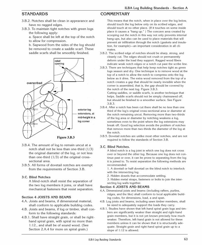
3.B.2. Notches shall be clean in appearance andhave no ragged edges.
3.B.3. To maintain tight notches with green logsthe following apply:a. Space shall be left at the top of the notchto allow for compression.b. Sapwood from the sides of the log shouldbe removed to create a saddle scarf. Thesesaddle scarfs shall be smoothly finished.
3.B.4. The amount of log to remain uncut at anotch shall not be less than one-third (1/3)the original diameter of the log, or not lessthan one-third (1/3) of the original cross-sectional area.
3.B.5. All forms of dovetail notches are exemptfrom the requirements of Section 3.B.
3.C. Blind NotchesA blind-notch shall resist the separation ofthe two log members it joins, or shall havemechanical fasteners that resist separation.
Section 4 JOISTS AND BEAMS4.A. Joists and beams, if dimensional material,
shall conform to applicable building codes.4.B. Joists and beams, if log or timber, shall con-
form to the following standards: 4.B.1. Shall have straight grain, or shall be right-
hand spiral grain, with spiral no more than1:12., and shall be of sound wood. (SeeSection 2.A.4 for more on spiral grain.)
This means that the notch, when in place over the log below,should touch the log below only on its scribed edges, andshould touch at no other place. (If it touches on some insideplace it causes a “hang up.” ) The concave area created byscooping out the notch in this way not only prevents internalhang-ups, but also can be used to place materials that willprevent air infiltration through the notch (gaskets and insula-tion, for example)—an important consideration in all cli-mates.
3.B.2. The scribed edge of notches should be sharp, strong, andcleanly cut. The edges should not crush or permanentlydeform under the load they support. Ragged wood fibersindicate weak notch edges or a notch cut past the scribe line.
3.B.3. There are techniques that help keep notches tight as greenlogs season and dry. One technique is to remove wood at thetop of a notch to allow the notch to compress onto the logbelow as it dries. The extra wood removed from the top of anotch creates a gap that should be nearly invisible when thecorner is assembled, that is, the gap should be covered bythe notch of the next log. Figure 3.B.3.Cutting saddles, or saddle scarfs, is another technique thathelps. Saddle scarfs should not be simply chainsawed off,but should be finished to a smoother surface. See Figure3.B.3.
3.B.4. After a notch has been cut there shall be no less than onethird of the log‘s original cross-sectional area or diameter atthe notch remaining uncut. Removing more than two-thirdsof the log area or diameter by notching weakens a log,sometimes even to the point where the log extensions maybreak off. Good log selection avoids the problem of notchesthat remove more than two-thirds the diameter of the log atthe notch.
3.B.5. Dovetail notches are unlike most other notches, and are notrequired to follow the standards of Section 3.B.
3.C. Blind Notches. A blind notch is a log joint in which one log does not crossover or beyond the other log. Because one log does not con-tinue past or over, it can be prone to separating from the logit is joined to. To resist separation the following methods arerecommended:1. A dovetail or half-dovetail on the blind notch to interlockwith the intersecting log.2. Hidden dowels that accommodate settling.3. Hidden metal straps, fasteners or bolts to join the inter-secting log walls together.
Section 4 JOISTS AND BEAMS4.A. Dimensional joists and beams (including rafters, purlins,
ridges, and the like) shall conform to local applicable build-ing codes, for dimensions, load, a and span.
4.B. Log joists and beams, including sawn timber members, shallbe sized to adequately support the loads they carry.
4.B.1. Studies have shown that left-hand spiral grain logs and tim-bers are significantly weaker than straight and right-handgrain members, but it is not yet known precisely how muchweaker. Therefore, left-hand grain is not allowed for thesemembers unless it can be shown that it is structurally ade-quate. Straight-grain and right-hand spiral grain up to aslope of 1:12 is allowed.
STANDARDS COMMENTARY
64 ILBA Log Buiding Standards
ILBA Log Building Standards - Section A
4.B.2. Shall be designed to resist all loads according to applicablebuilding codes and accepted engineering practice.
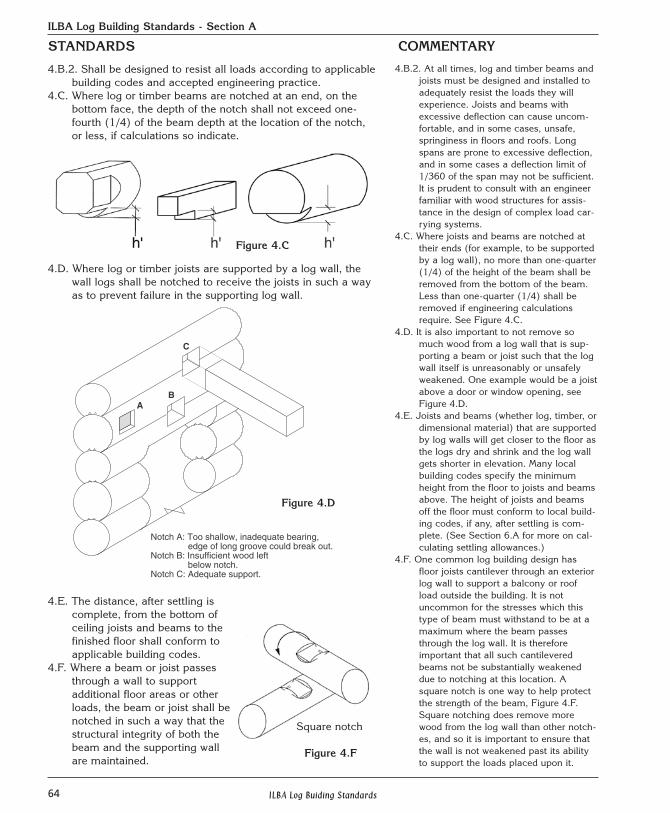
4.C. Where log or timber beams are notched at an end, on thebottom face, the depth of the notch shall not exceed one-fourth (1/4) of the beam depth at the location of the notch,or less, if calculations so indicate.
4.D. Where log or timber joists are supported by a log wall, thewall logs shall be notched to receive the joists in such a wayas to prevent failure in the supporting log wall.
4.E. The distance, after settling iscomplete, from the bottom ofceiling joists and beams to thefinished floor shall conform toapplicable building codes.
4.F. Where a beam or joist passesthrough a wall to support additional floor areas or otherloads, the beam or joist shall benotched in such a way that thestructural integrity of both thebeam and the supporting wallare maintained.
4.B.2. At all times, log and timber beams andjoists must be designed and installed toadequately resist the loads they willexperience. Joists and beams withexcessive deflection can cause uncom-fortable, and in some cases, unsafe,springiness in floors and roofs. Longspans are prone to excessive deflection,and in some cases a deflection limit of1/360 of the span may not be sufficient.It is prudent to consult with an engineerfamiliar with wood structures for assis-tance in the design of complex load car-rying systems.
4.C. Where joists and beams are notched attheir ends (for example, to be supportedby a log wall), no more than one-quarter(1/4) of the height of the beam shall beremoved from the bottom of the beam.Less than one-quarter (1/4) shall beremoved if engineering calculationsrequire. See Figure 4.C.
4.D. It is also important to not remove somuch wood from a log wall that is sup-porting a beam or joist such that the logwall itself is unreasonably or unsafelyweakened. One example would be a joistabove a door or window opening, seeFigure 4.D.
4.E. Joists and beams (whether log, timber, ordimensional material) that are supportedby log walls will get closer to the floor asthe logs dry and shrink and the log wallgets shorter in elevation. Many localbuilding codes specify the minimumheight from the floor to joists and beamsabove. The height of joists and beamsoff the floor must conform to local build-ing codes, if any, after settling is com-plete. (See Section 6.A for more on cal-culating settling allowances.)
4.F. One common log building design hasfloor joists cantilever through an exteriorlog wall to support a balcony or roofload outside the building. It is notuncommon for the stresses which thistype of beam must withstand to be at amaximum where the beam passesthrough the log wall. It is thereforeimportant that all such cantileveredbeams not be substantially weakeneddue to notching at this location. Asquare notch is one way to help protectthe strength of the beam, Figure 4.F.Square notching does remove morewood from the log wall than other notch-es, and so it is important to ensure thatthe wall is not weakened past its abilityto support the loads placed upon it.
STANDARDS COMMENTARY
AB
C
Notch A: Too shallow, inadequate bearing, edge of long groove could break out.Notch B: Insufficient wood left below notch.Notch C: Adequate support.
Figure 4.C
Figure 4.D
Square notch
Figure 4.F
65ILBA Log Buiding Standards
ILBA Log Building Standards - Section A
4.G. Where an interior beam extends through a wall to the exteri-or it shall be protected from the weather so that its structur-al integrity is maintained. The intersection of the beam andwall shall be constructed to restrict weather and insect infil-tration. See also Sections 7.F and 7.G.
4.H. Log joists and beams shall be flattened on top to a mini-mum of 2.5 centimeters (1 inch) where they support floor-ing or framing.
Section 5 WINDOW AND DOOR OPENINGS5.A. Settling space shall be provided for all doors and windows
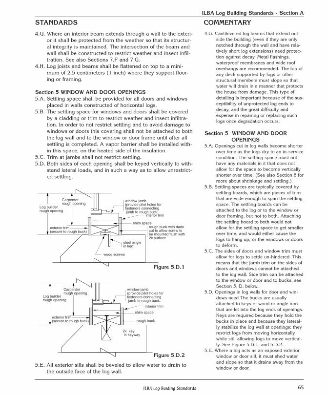
placed in walls constructed of horizontal logs.5.B. The settling space for windows and doors shall be covered
by a cladding or trim to restrict weather and insect infiltra-tion. In order to not restrict settling and to avoid damage towindows or doors this covering shall not be attached to boththe log wall and to the window or door frame until after allsettling is completed. A vapor barrier shall be installed with-in this space, on the heated side of the insulation.
5.C. Trim at jambs shall not restrict settling.5.D. Both sides of each opening shall be keyed vertically to with-
stand lateral loads, and in such a way as to allow unrestrict-ed settling.
5.E. All exterior sills shall be beveled to allow water to drain tothe outside face of the log wall.
4.G. Cantilevered log beams that extend out-side the building (even if they are onlynotched through the wall and have rela-tively short log extensions) need protec-tion against decay. Metal flashings,waterproof membranes and wide roofoverhangs are recommended. The top ofany deck supported by logs or otherstructural members must slope so thatwater will drain in a manner that protectsthe house from damage. This type ofdetailing is important because of the sus-ceptibility of unprotected log ends todecay, and the great difficulty andexpense in repairing or replacing suchlogs once degradation occurs.
Section 5 WINDOW AND DOOR OPENINGS
5.A. Openings cut in log walls become shorterover time as the logs dry to an in-servicecondition. The settling space must nothave any materials in it that does notallow for the space to become verticallyshorter over time. (See also Section 6 formore about shrinkage and settling.)
5.B. Settling spaces are typically covered bysettling boards, which are pieces of trimthat are wide enough to span the settlingspace. The settling boards can beattached to the log or to the window ordoor framing, but not to both. Attachingthe settling board to both would notallow for the settling space to get smallerover time, and would either cause thelogs to hang up, or the windows or doorsto deform.
5.C. The sides of doors and window trim mustallow for logs to settle un-hindered. Thismeans that the jamb trim on the sides ofdoors and windows cannot be attachedto the log wall. Side trim can be attachedto the window or door and to bucks, seeSection 5. D. below.
5.D. Openings in log walls for door and win-dows need The bucks are usuallyattached to keys of wood or angle ironthat are let into the log ends of openings.Keys are required because they hold thebucks in place and because they lateral-ly stabilize the log wall at openings: theyrestrict logs from moving horizontallywhile still allowing logs to move vertical-ly. See Figure 5.D.1. and 5.D.2.
5.E. Where a log acts as an exposed exteriorwindow or door sill, it must shed waterand slope so that it drains away from thewindow or door.
STANDARDS COMMENTARY
Log builder rough opening
Carpenter rough opening
window jamb(provide pilot holes forfasteners connecting jamb to rough buck.
interior trim
shim spacerough buck with dadocut to allow screw tobe mounted flush with2x surface
wood screws
exterior trim(secure to rough buck)
������
steel angle in kerf
Carpenter rough opening
interior trim
shim space
rough buck
2x key in keyway
Log builder rough opening
window jamb (provide pilot holes forfasteners connecting jamb to rough buck.
exterior trim(secure to rough buck)
Figure 5.D.1
Figure 5.D.2
66 ILBA Log Buiding Standards
ILBA Log Building Standards - Section A
5.F. The position of openings in walls construct-ed of horizontal logs shall conform to thefollowing:
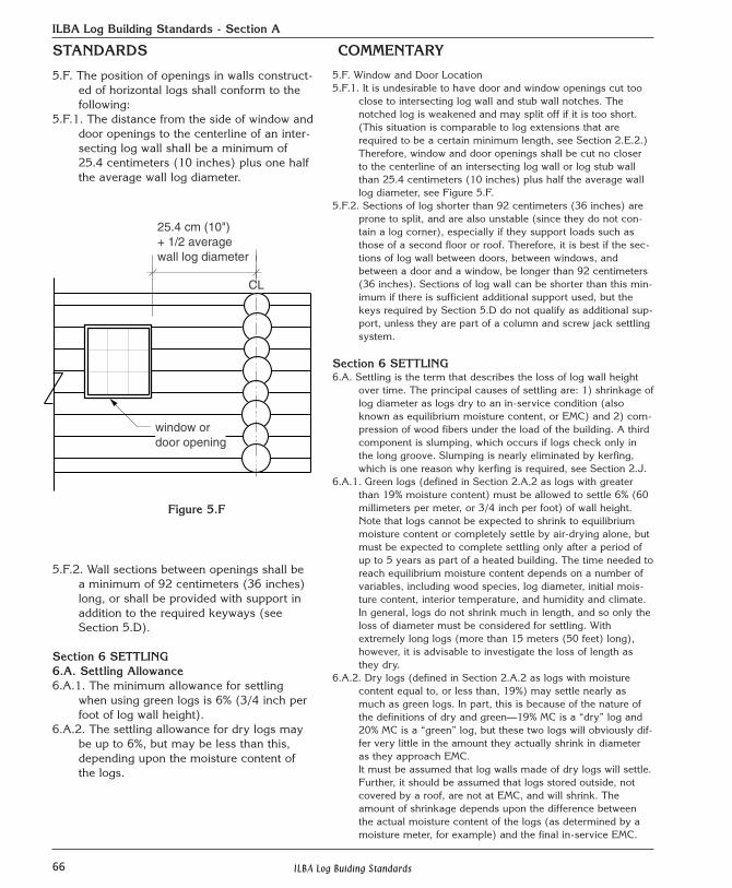
5.F.1. The distance from the side of window anddoor openings to the centerline of an inter-secting log wall shall be a minimum of25.4 centimeters (10 inches) plus one halfthe average wall log diameter.
5.F.2. Wall sections between openings shall bea minimum of 92 centimeters (36 inches)long, or shall be provided with support inaddition to the required keyways (seeSection 5.D).
Section 6 SETTLING6.A. Settling Allowance6.A.1. The minimum allowance for settling
when using green logs is 6% (3/4 inch perfoot of log wall height).
6.A.2. The settling allowance for dry logs maybe up to 6%, but may be less than this,depending upon the moisture content ofthe logs.
5.F. Window and Door Location5.F.1. It is undesirable to have door and window openings cut too
close to intersecting log wall and stub wall notches. Thenotched log is weakened and may split off if it is too short.(This situation is comparable to log extensions that arerequired to be a certain minimum length, see Section 2.E.2.)Therefore, window and door openings shall be cut no closerto the centerline of an intersecting log wall or log stub wallthan 25.4 centimeters (10 inches) plus half the average walllog diameter, see Figure 5.F.
5.F.2. Sections of log shorter than 92 centimeters (36 inches) areprone to split, and are also unstable (since they do not con-tain a log corner), especially if they support loads such asthose of a second floor or roof. Therefore, it is best if the sec-tions of log wall between doors, between windows, andbetween a door and a window, be longer than 92 centimeters(36 inches). Sections of log wall can be shorter than this min-imum if there is sufficient additional support used, but thekeys required by Section 5.D do not qualify as additional sup-port, unless they are part of a column and screw jack settlingsystem.
Section 6 SETTLING6.A. Settling is the term that describes the loss of log wall height
over time. The principal causes of settling are: 1) shrinkage oflog diameter as logs dry to an in-service condition (alsoknown as equilibrium moisture content, or EMC) and 2) com-pression of wood fibers under the load of the building. A thirdcomponent is slumping, which occurs if logs check only inthe long groove. Slumping is nearly eliminated by kerfing,which is one reason why kerfing is required, see Section 2.J.
6.A.1. Green logs (defined in Section 2.A.2 as logs with greaterthan 19% moisture content) must be allowed to settle 6% (60millimeters per meter, or 3/4 inch per foot) of wall height.Note that logs cannot be expected to shrink to equilibriummoisture content or completely settle by air-drying alone, butmust be expected to complete settling only after a period ofup to 5 years as part of a heated building. The time needed toreach equilibrium moisture content depends on a number ofvariables, including wood species, log diameter, initial mois-ture content, interior temperature, and humidity and climate. In general, logs do not shrink much in length, and so only theloss of diameter must be considered for settling. Withextremely long logs (more than 15 meters (50 feet) long),however, it is advisable to investigate the loss of length asthey dry.
6.A.2. Dry logs (defined in Section 2.A.2 as logs with moisturecontent equal to, or less than, 19%) may settle nearly asmuch as green logs. In part, this is because of the nature ofthe definitions of dry and green—19% MC is a “dry” log and20% MC is a “green” log, but these two logs will obviously dif-fer very little in the amount they actually shrink in diameteras they approach EMC. It must be assumed that log walls made of dry logs will settle.Further, it should be assumed that logs stored outside, notcovered by a roof, are not at EMC, and will shrink. Theamount of shrinkage depends upon the difference betweenthe actual moisture content of the logs (as determined by amoisture meter, for example) and the final in-service EMC.
STANDARDS COMMENTARY
CL
25.4 cm (10")+ 1/2 averagewall log diameter
window ordoor opening
Figure 5.F
67ILBA Log Buiding Standards
ILBA Log Building Standards - Section A
6.B. Adequate provisions shall be made forsettling at all openings, load bearingposts, chimneys, fireplaces, interior framepartition walls, electrical entrance boxesand conduits, plumbing vents and drains,second story water and gas pipes, stair-cases, downspouts, heating and air condi-tioning ducts, kitchen cabinets and allother non-settling portions of the building.
6.C. The log contractor shall provide informa-tion to the general contractor to helpguide sub-contractors in the use of tech-niques applicable to their trade to dealwith the unique characteristics of log con-struction, and specifically how each tradeshould accommodate for settling.
6.D. All caulking and weather-sealing mustaccount for the change in diameter andshape of the logs as they dry.
Section 7 ROOFS AND ROOF SUPPORTSYSTEMS
7.A. If constructed of dimensional material,roofs shall conform to applicable buildingcodes.
7.B. If constructed of log or timber, roof sys-tems shall conform to the following stan-dards:
7.B.1. Shall be constructed only of straight-grain, or moderately right-hand spiralgrain material (see Section 2.A.4 for defi-nitions of spiral grain).
7.B.2. Shall be designed to resist loadsaccording to applicable building codesand accepted engineering practice.
7.B.3. Where beams are notched at an end, ontheir bottom face, the depth of the notchshall not exceed one-fourth (1/4) thebeam depth at the location of the notch,or less if calculations so indicate.
7.C. The distance from the bottom of roofbeams to the finished floor must conformto applicable building codes after settlingis complete.
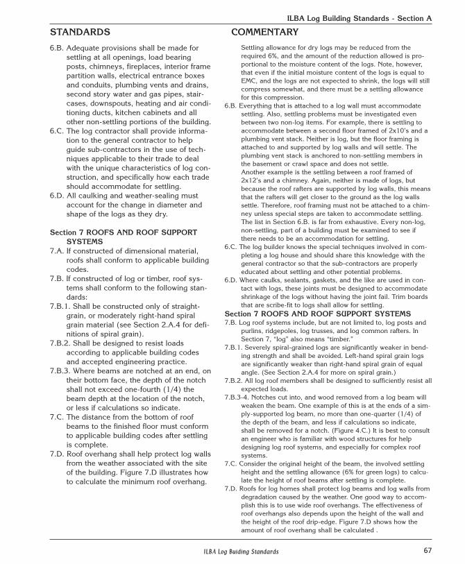
7.D. Roof overhang shall help protect log wallsfrom the weather associated with the siteof the building. Figure 7.D illustrates howto calculate the minimum roof overhang.
Settling allowance for dry logs may be reduced from therequired 6%, and the amount of the reduction allowed is pro-portional to the moisture content of the logs. Note, however,that even if the initial moisture content of the logs is equal toEMC, and the logs are not expected to shrink, the logs will stillcompress somewhat, and there must be a settling allowancefor this compression.
6.B. Everything that is attached to a log wall must accommodatesettling. Also, settling problems must be investigated evenbetween two non-log items. For example, there is settling toaccommodate between a second floor framed of 2x10’s and aplumbing vent stack. Neither is log, but the floor framing isattached to and supported by log walls and will settle. Theplumbing vent stack is anchored to non-settling members inthe basement or crawl space and does not settle.Another example is the settling between a roof framed of2x12’s and a chimney. Again, neither is made of logs, butbecause the roof rafters are supported by log walls, this meansthat the rafters will get closer to the ground as the log wallssettle. Therefore, roof framing must not be attached to a chim-ney unless special steps are taken to accommodate settling. The list in Section 6.B. is far from exhaustive. Every non-log,non-settling, part of a building must be examined to see ifthere needs to be an accommodation for settling.
6.C. The log builder knows the special techniques involved in com-pleting a log house and should share this knowledge with thegeneral contractor so that the sub-contractors are properlyeducated about settling and other potential problems.
6.D. Where caulks, sealants, gaskets, and the like are used in con-tact with logs, these joints must be designed to accommodateshrinkage of the logs without having the joint fail. Trim boardsthat are scribe-fit to logs shall allow for settling.
Section 7 ROOFS AND ROOF SUPPORT SYSTEMS7.B. Log roof systems include, but are not limited to, log posts and
purlins, ridgepoles, log trusses, and log common rafters. InSection 7, “log” also means “timber.”
7.B.1. Severely spiral-grained logs are significantly weaker in bend-ing strength and shall be avoided. Left-hand spiral grain logsare significantly weaker than right-hand spiral grain of equalangle. (See Section 2.A.4 for more on spiral grain.)
7.B.2. All log roof members shall be designed to sufficiently resist allexpected loads.
7.B.3-4. Notches cut into, and wood removed from a log beam willweaken the beam. One example of this is at the ends of a sim-ply-supported log beam, no more than one-quarter (1/4) ofthe depth of the beam, and less if calculations so indicate,shall be removed for a notch. (Figure 4.C.) It is best to consultan engineer who is familiar with wood structures for helpdesigning log roof systems, and especially for complex roofsystems.
7.C. Consider the original height of the beam, the involved settlingheight and the settling allowance (6% for green logs) to calcu-late the height of roof beams after settling is complete.
7.D. Roofs for log homes shall protect log beams and log walls fromdegradation caused by the weather. One good way to accom-plish this is to use wide roof overhangs. The effectiveness ofroof overhangs also depends upon the height of the wall andthe height of the roof drip-edge. Figure 7.D shows how theamount of roof overhang shall be calculated .
STANDARDS COMMENTARY
68 ILBA Log Buiding Standards
ILBA Log Building Standards - Section A
7.E. The roof shall protect all roof structural membersfrom the weather associated with the site of thebuilding.
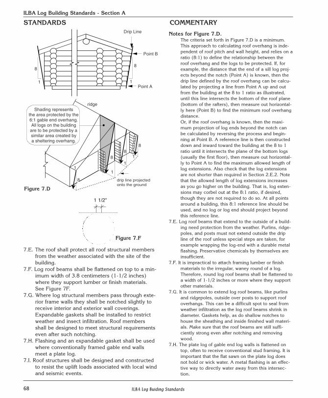
7.F. Log roof beams shall be flattened on top to a min-imum width of 3.8 centimeters (1-1/2 inches)where they support lumber or finish materials.See Figure 7F.
7.G. Where log structural members pass through exte-rior frame walls they shall be notched slightly toreceive interior and exterior wall coverings.Expandable gaskets shall be installed to restrictweather and insect infiltration. Roof membersshall be designed to meet structural requirementseven after such notching.
7.H. Flashing and an expandable gasket shall be usedwhere conventionally framed gable end wallsmeet a plate log.
7.I. Roof structures shall be designed and constructedto resist the uplift loads associated with local windand seismic events.
Notes for Figure 7.D.The criteria set forth in Figure 7.D is a minimum.This approach to calculating roof overhang is inde-pendent of roof pitch and wall height, and relies on aratio (8:1) to define the relationship between theroof overhang and the logs to be protected. If, forexample, the distance that the end of a sill log proj-ects beyond the notch (Point A) is known, then thedrip line defined by the roof overhang can be calcu-lated by projecting a line from Point A up and outfrom the building at the 8 to 1 ratio as illustrated,until this line intersects the bottom of the roof plane(bottom of the rafters), then measure out horizontal-ly here (Point B) to find the minimum roof overhangdistance.Or, if the roof overhang is known, then the maxi-mum projection of log ends beyond the notch canbe calculated by reversing the process and begin-ning at Point B. A reference line is then constructeddown and inward toward the building at the 8 to 1ratio until it intersects the plane of the bottom logs(usually the first floor), then measure out horizontal-ly to Point A to find the maximum allowed length oflog extensions. Also check that the log extensionsare not shorter than required in Section 2.E.2. Notethat the allowed length of log extensions increasesas you go higher on the building. That is, log exten-sions may corbel out at the 8:1 ratio, if desired,though they are not required to do so. At all pointsaround a building, this 8:1 reference line should beused, and no log or log end should project beyondthis reference line.
7.E. Log roof beams that extend to the outside of a build-ing need protection from the weather. Purlins, ridge-poles, and posts must not extend outside the dripline of the roof unless special steps are taken, forexample wrapping the log-end with a durable metalflashing. Preservative chemicals by themselves areinsufficient.
7.F. It is impractical to attach framing lumber or finishmaterials to the irregular, waney round of a log.Therefore, round log roof beams shall be flattened toa width of 1-1/2 inches or more where they supportother materials.
7.G. It is common to extend log roof beams, like purlinsand ridgepoles, outside over posts to support roofoverhangs. This can be a difficult spot to seal fromweather infiltration as the log roof beams shrink indiameter. Gaskets help, as do shallow notches tohouse the sheathing and inside finished wall materi-als. Make sure that the roof beams are still suffi-ciently strong even after notching and removingwood.
7.H. The plate log of gable end log walls is flattened ontop, often to receive conventional stud framing. It isimportant that the flat sawn on the plate log doesnot hold or wick water. A metal flashing is an effec-tive way to directly water away from this intersec-tion.
6
drip line projectonto the ground
1
88
ridge
1
1
8
1
Point B
Point A
Drip Line
8
1
8
1
8
Shading representsthe area protected by the6:1 gable end overhang.All logs on the building
are to be protected by asimilar area created bya sheltering overhang.
drip line projectedonto the ground
Figure 7.D
Figure 7.F
STANDARDS COMMENTARY
1 1/2"
69ILBA Log Buiding Standards
ILBA Log Building Standards - Section A
STANDARDS COMMENTARY
7.J. Where roof structures are supported on outriggers,which are in turn supported on log extensions, theextension log carrying the outrigger shall be supportedby additional log extensions (a minimum of two exten-sions below the extension carrying the outrigger) insuch a way as to support all loads from the outriggerin a manner other than by cantilever action, unless thelog extension carrying the outrigger is designed andconstructed as a structural cantilever. (See alsoSection 2.E.4.)
Section 8 ELECTRICALShall comply with applicable codes, with accommodations
where necessary for pre-wiring and wall settlingallowance. (See also Section 6.B.)
Section 9 PLUMBING9.A. Shall comply with applicable codes, with settling con-
siderations. See also Section 6.9.B. A plumbing pipe shall travel through a log wall only
perpendicular to the long axis of the logs, and shall belevel or nearly level.
7.J. Log outriggers are roof plates outside of, andparallel to, log eave walls. Do not use just onelog extension (log flyway) to support the outrig-ger unless it can be shown that one extension issufficiently stiff and strong. In any case, nomatter how the outrigger is supported, itsmeans of support must be sufficient. (SeeSection 2.E for more on log extensions.)
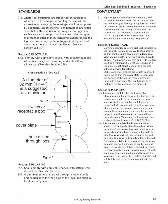
Section 8 ELECTRICALCommon practice is to pre-drill vertical holes inthe log wall, from long groove to long groove,so that the holes are completely hidden fromview and no electrical wiring is exposed insideor out. (A diameter of 32 mm or 1-1/4” is oftenused as a minimum.) Do not use conduit in alog wall. Do not attach conduit to a log wallwithout allowing for settling. Outlets and switch boxes are usually mortisedinto a log so that the cover plate is even withthe surface of the log, or, more commonly,flush with a portion of the log that has beenflattened for this purpose, see Figure 8.
Section 9 PLUMBING9.A. Investigate carefully the need for settling
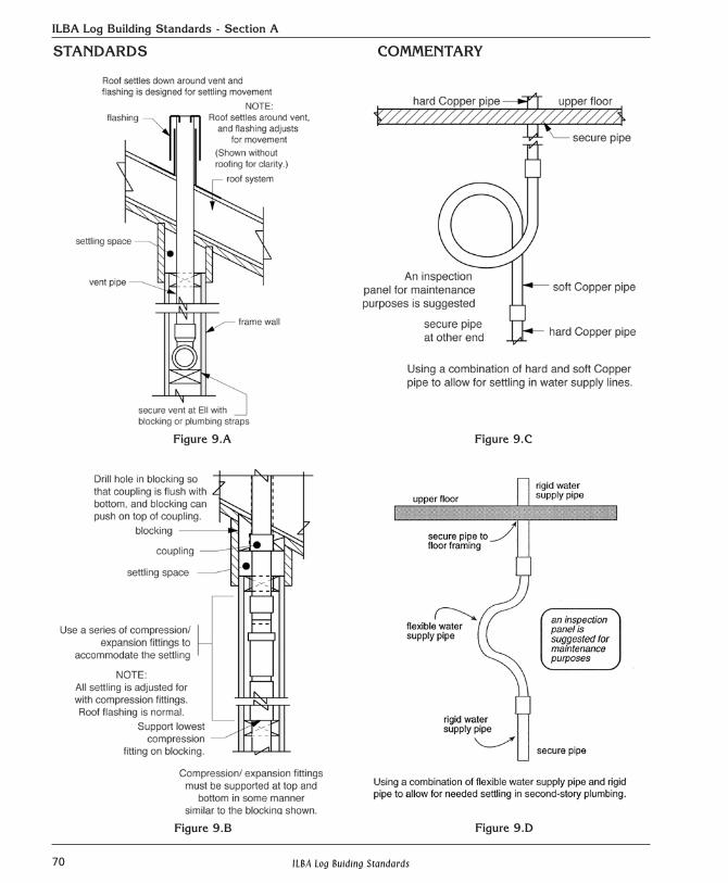
allowances in all plumbing for log homes. It isusually preferable to run plumbing in framewalls vertically without horizontal offsets,though offsets are possible, if settling consider-ations are carefully made. Supply pipes to asecond floor can allow for settling by incorpo-rating a loop that opens as the second floorloses elevation. Waste and vent pipes can havea slip joint. See Figure 9..A, 9.B, 9.C, 9.D.
9.B. It is usually not advisable to run plumbingwaste, vent or supply pipes through or withinlog walls. If they must, however, pipes can runperpendicular and level through a log wall. Apipe that runs vertically up through a log wall,or a pipe that runs horizontally within a log wall(for example, lying in a long groove) can neveragain be serviced without cutting the log wallapart—a drastic event that is difficult to repair. Because supply lines are known to age, fill withscale and sometimes to leak and because theventing of sewer gases is a matter of health andsafety it is best to not locate plumbing in logwalls.
wireswitch or
receptacle box
cover plate
hole drilledthrough logs
A diameter of32 mm (1-1/4")is a suggestedas a minimum
cross-section of log wall
Figure 8
70 ILBA Log Buiding Standards
ILBA Log Building Standards - Section A
STANDARDS COMMENTARY
Figure 9.A Figure 9.C
Figure 9.B Figure 9.D
71ILBA Log Buiding Standards
ILBA Log Building Standards - Section A
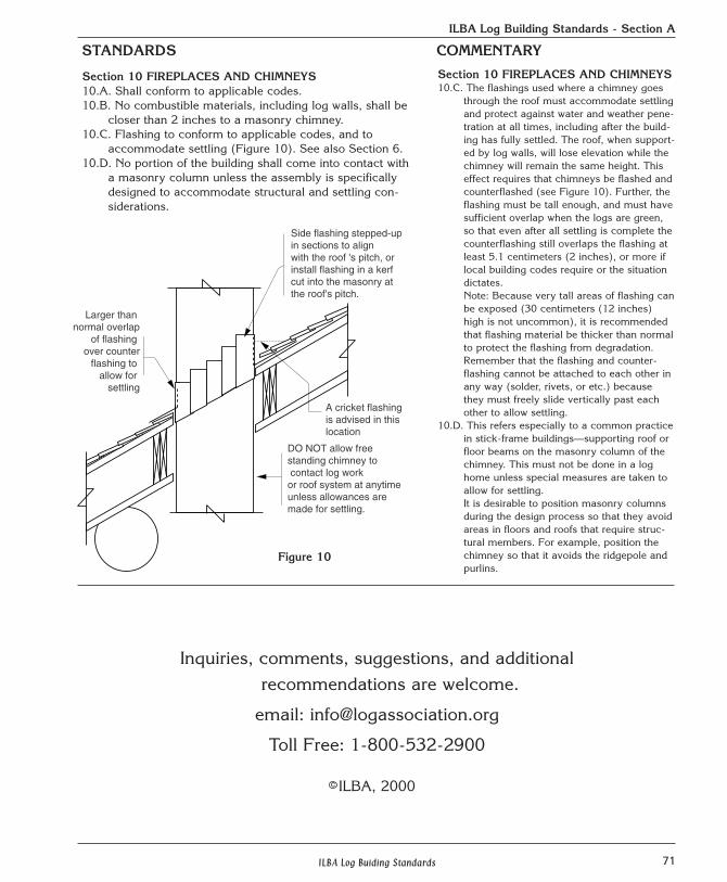
Section 10 FIREPLACES AND CHIMNEYS10.A. Shall conform to applicable codes. 10.B. No combustible materials, including log walls, shall be
closer than 2 inches to a masonry chimney.10.C. Flashing to conform to applicable codes, and to
accommodate settling (Figure 10). See also Section 6.10.D. No portion of the building shall come into contact with
a masonry column unless the assembly is specificallydesigned to accommodate structural and settling con-siderations.
Section 10 FIREPLACES AND CHIMNEYS10.C. The flashings used where a chimney goes
through the roof must accommodate settlingand protect against water and weather pene-tration at all times, including after the build-ing has fully settled. The roof, when support-ed by log walls, will lose elevation while thechimney will remain the same height. Thiseffect requires that chimneys be flashed andcounterflashed (see Figure 10). Further, theflashing must be tall enough, and must havesufficient overlap when the logs are green,so that even after all settling is complete thecounterflashing still overlaps the flashing atleast 5.1 centimeters (2 inches), or more iflocal building codes require or the situationdictates.Note: Because very tall areas of flashing canbe exposed (30 centimeters (12 inches)high is not uncommon), it is recommendedthat flashing material be thicker than normalto protect the flashing from degradation.Remember that the flashing and counter-flashing cannot be attached to each other inany way (solder, rivets, or etc.) becausethey must freely slide vertically past eachother to allow settling.
10.D. This refers especially to a common practicein stick-frame buildings—supporting roof orfloor beams on the masonry column of thechimney. This must not be done in a loghome unless special measures are taken toallow for settling. It is desirable to position masonry columnsduring the design process so that they avoidareas in floors and roofs that require struc-tural members. For example, position thechimney so that it avoids the ridgepole andpurlins.
STANDARDS COMMENTARY
Side flashing stepped-upin sections to alignwith the roof 's pitch, or install flashing in a kerfcut into the masonry atthe roof's pitch.
Larger than normal overlap
of flashing over counter flashing to
allow for settling
A cricket flashing is advised in thislocation
DO NOT allow free standing chimney to contact log work or roof system at anytime unless allowances are made for settling.
Figure 10
Inquiries, comments, suggestions, and additional recommendations are welcome.
email: [email protected]
Toll Free: 1-800-532-2900
ILBA, 2000c
72 ILBA Log Buiding Standards
ILBA Log Building Standards - Section B
2.A.2. Green or dry logs may be used for con-struction.
2.B. Log walls shall be constructed of logs laid inhorizontal courses with a chink gap betweenlogs and with interlocking notches at thecorners.
2.D. Chink Gap2.D.1. Logs in walls shall have a continuous
chink gap along the length of each log(except where interrupted by required struc-tural blocking).
2.D.3. Minimum length of chink joint shall be 4”.2.D.7. Blocking of not less than 3 1/2“ wide x 4”
deep in shall be installed in the chink gap.Blocking height will vary. The blocking shallbe placed at each side of door or windowopenings and at intervals determined bylocal codes and conditions. Blocking shallbe installed so that flats are level in bothdirections and centered on the chink gap.Log walls with openings cut for doors, win-dows and passageways require blocking ateach side of the opening to support logends. These opening may require structuralanalysis.
2.D.8. Log wall pinning is necessary to resistapplicable wind and seismic loads.
2.D.9. Synthetic chinking material shall beapplied in chink gaps in such a manner asto resist water, air and insect infiltration. Atall times, the chinking shall conceal andprotect through-bolts, pins, dowels, kerfs,electrical holes, blocking, and the like. Allchinking shall be repaired upon visible evi-dence of cracking or pulling away from logs.Synthetic chinking shall be installed accord-ing to joint designs that will favor “cohesive”failure of the chinking (rather than “adhe-sive” failure) if unavoidably extreme move-ment should occur in a joint.
2.E.5. At load bearing extensions or whereblocking or pins are visible, chinking mustbe applied.
2.G.3. The notch and chinking shall at all timescompletely hide a splice and its fastenersand help protect splices against weather andinsect infiltration.
STANDARDS COMMENTARY
Section B: 2000 LOG BUILDING CHINKING STANDARDS
2.A.2. Same as full scribe. For purposes of chinking appli-cation, check with manufacturer as to proper moisturecontent of logs at the time of chinking application.
2.B. See chink gap section 2.D. for more details.
Chink Gap2.D. The chink gap is a continuous air space separating
logs between interlocking corners and/or window anddoor openings; it should be interrupted only byrequired structural blocking.
2.D.1. Chink gaps will be continuous without “holdups” atany point along the length.
2.D.3. The width of chinking from inside face to outside facewill vary depending upon chink gap size and log diam-eter. 8” is the minimum log diameter.
2.D.7. Blocking supports the log walls at the span and atdoor and window openings. The flats, being level inboth directions and centered on the chink gap, preventblocking from rolling in the chink gap. An engineeringanalysis is recommended to determine distancebetween blocking. Additional blocking may berequired at load bearing points. If blocking supportsthe log end at an opening, it must be installed so asnot to hinder settling, buck installation and chinkinstallation. The blocking should fall in a vertical col-umn. In addition, pinning will provide stabilityExamples of blocking:1”x4” or 2”x4” kiln dried lumber, 4” long3 1/2" x4” plywood 1/8” and thicker3 1/2” x4”x1/8” masonite30# feltSee diagrams 2.D.1. and 2.D.2.
2.D.8. The amount and kind of wall pinning depends uponlocal conditions and codes. In areas of extreme windand seismic load conditions, continuous through bolt-ing the full height of the logs can be an effective tech-nique.Examples of wall pinning:Wood dowels, smooth shaft steel pins, through-bolts,lag screws, steel bar or log stub walls.
2.D.9. Synthetic chinking should always be installed accord-ing to manufacturer’s specifications. Moisture contentof the logs should be checked. Some manufacturersrecommend a 20% or less moisture content. For tradi-tional or local chink mixtures, check local building orenergy codes to see if they are acceptable. Cohesionfailure of the chinking is preferred because it is easier,faster and much less expensive to repair.
2.E.5. All extensions between heated and unheated spaceshall be chinked to cover blocking and pins. Othersareas are optional.
2.F.1. Same as full scribe standards.2.G.3. Same as full scribe standard.
73ILBA Log Buiding Standards
ILBA Log Building Standards - Section B
2.H.1 A header log shall have no more than half of itsvertical height removed at the location of open-ings, unless it is covered by at least one more fulllog. In all cases, the header log must be support-ed at each side by blocking and wall pinning andbe adequate for structural requirements.
2.l.2. Where conventional framing meets a plate log,this intersection shall have chinking, elastomericcaulking or an expandable gasket to accommo-date anticipated shrinkage of the log plate and torestrict weather and insect filtration.
2.J.2. The depth of the top kerf shall be at least onequarter of the height of the log and shall be nodeeper than one half the diameter.
Section ll-Chinking (Synthetic)ll.A.l. Before applying the chinking material, backer
rod shall be installed in the chink gap. The backerrod shall fit snugly into the gap via either frictionor appropriate mechanical fasteners.
ll.A.2. Synthetic chinking material shall be applied tothe backer rod from notch to notch or notch todoor/window opening in such a manner that it isself-draining and restricts air, water and insectinfiltration.
ll.A.3. Where appropriate internal gaskets are installed,no chinking of notches and joints is required. Allother notches and joints shall be chinked.
ll.A.4. Chinking shall be applied with sufficient appli-cation pressure and tooling to properly “wet out”and establish strong adhesion to the contact sur-faces of the logs. Such pressure and tooling caneliminate regions where the chinking might other-wise pull away and provide entry to moisture, air,dust or insects.
ll.A.5. Where chinking is to be applied over structuralblocking, as much as possible, bond-breakingmaterials such as, backer rod tape, etc., must beapplied between the blocking and the chinking toavoid 3-point adhesion.
ll.A.6. The chinking shall be applied to surfaces thatare known to provide a suitable substrate forstrong chinking adhesion. Coatings containingwax and oils that might lead to poor adhesion andchinking failure are to be avoided.
ll.A.7. Fire-rated chinking systems shall be in carefulcompliance with the manufacturer’s specifica-tions.
STANDARDS COMMENTARY
2.H.1. Same as full scribe standard.2.l.2. Same as full scribe standard.2.J.2. The top kerf must be deep enough to promote
checking. The amount of wood removed by thekerf should be between 1/4 and 1/2 of the logdepth.
Section ll-Chinking (Synthetic)ll. Chinking is the material that goes between the logs
to fill the chink gap. It acts as a barrier againstair, insects, moisture and dust infiltration andacts as a form of insulation.
ll.A.l. Backer rod comes in many forms. Each manu-facturer has its preference as to style (flat orround) and type (closed cell or open cell).Using the manufacturer’s guidelines is recom-mended. When changing size in backer rod dueto varying chink gap, do so gradually to allowfor a smooth transition in the chinking material.(Note: Installing backer rod with adhesives,spray or otherwise, can lead to poor adhesionof chinking. Follow manufacturer’s guidelines.)
ll.A.2. Synthetic chinking shall be applied accordingto manufacturer’s guidelines. It should have anattractive, natural texture. The edges of the jointshould be clean and crisp where the chinkingmeets the log. The backer rod should not showthrough the chinking at any point. See figurell.A..
ll.A.3. When internal gaskets are used, air, water andinsect infiltration is restricted. Without gaskets,the chinking material becomes the barrier toinfiltration.
ll.A.4. Wetout is the condition where too much of arelease agent (isopropyl alcohol combined with50% water) is used to trowel the chinking mate-rial. Excessive wetting may prevent the chink-ing from properly adhering to the wood.