sperry · pdf filetary speed log, it became possible ... the international maritime...
TRANSCRIPT
Sperry Marine
© 2005 Northrop Grumman


Table of ContentsCHAPTER 1: WHERE ARE YOU GOING?
CHAPTER 2: TRANSMITTING HEADING DEVICES
CHAPTER 3: DETERMINING HEADING BY SATELLITE
CHAPTER 4: CARRIAGE REQUIREMENTS
CHAPTER 5: PERFORMANCE STANDARDS
CHAPTER 6: A HYBRID SOLUTION
REFERENCES
ACRONYMS AND ABBREVIATIONS
USEFUL LINKS

6 A P R A C T I C A L G U I D E T O
1 CHAPTER 1
Where Are You Going?It’s often said that the most importantrevolution in marine navigation tookplace when the magnetic compasswas invented. Its exact origins areforever shrouded in the mists ofhistory, but historical references tomagnetic compasses go back atleast 1,000 years. With the magneticcompass, coupled with a rudimen-tary speed log, it became possiblefor mariners to leave the safety andsecurity of the coastline and ventureout onto the open ocean.
For centuries, dead reckoning withmagnetic compass and speed log,updated with periodic observations
of celestial bodies, defined the state of the art inmarine navigation.
Then, in the last half of the 20th century, the electronicsrevolution swept through the marine industry, bringingwith it hyperbolic radionavigation aids like Decca,Omega and Loran, followed by satellite navigationsystems such as Transit, GPS and Glonass, whichprovided real-time position fixing, and eliminating muchof the need for traditional dead reckoning.
But some things, it seems, never change. Determiningthe ship’s heading and speed are still fundamentalrequirements in marine navigation. In fact, the prolifera-tion of electronic systems, such as Electronic Chart

7T R A N S M I T T I N G H E A D I N G D E V I C E S
Display and Information Systems (ECDIS), Automatic Identifica-tion Systems (AIS), Automatic Radar Plotting Aids (ARPA) andVoyage Data Recorders (VDR), has create a need for headingreference data to function properly.
Hence the appearance of a new type of navigation systems –transmitting heading devices (THD).
In this booklet, we will explain how satellite-based technology cansatisfy this requirement for stable, accurate and reasonably pricedheading data. In this booklet, we will explain how Global Naviga-tion Satellite Systems (GNSS) can satisfy this requirement.
8 A P R A C T I C A L G U I D E T O
2 CHAPTER 2
Transmitting Heading DevicesAutomatic Identification Systems (AIS), Voyage DataRecorders (VDR), Automatic Radar Plotting Aids(ARPA) and other modern ship electronic systems,which are mandated for ships under the Safety of Lifeat Sea (SOLAS) Convention, require accurate real-timeinputs of the ship’s heading to function properly.
The International Maritime Organization (IMO) there-fore has adopted regulations governing the new typesof heading reference systems that provide thesecritical inputs.
A Transmitting Heading Device (THD) is defined by theIMO as “an electrical device that provides informationabout the ship’s true heading.” The ship’s heading datamust be provided in a standard format that can be usedby other equipment as specified in IMO regulations.(Note that the definition calls for true, not magnetic,heading.)
The THD consists of two basic parts: the sensing part(a device capable of detecting heading information)and the transmitting part (a device which receivesheading information from the sensing part and con-verts it into the required accurate signal).
The IMO documents do not specify what sort of sensormust be used to measure the ship’s true heading.Thus, the THD heading sensor could be satisfied by agyrocompass or an electronic magnetic compass,corrected for variation and deviation and capable ofmeeting the minimum standards for reliability andresolution. The advent of high-accuracy, real-timeGlobal Navigation Satellite Systems (GNSS) such as

9T R A N S M I T T I N G H E A D I N G D E V I C E S
GPS opens a third possibility, and in the next chapter we willdiscuss how the satellite signals can be used to determine theship’s true heading – at a fraction of the cost of a gyrocompass.
SensorPart
TransmittingPart
ARPA
VDR
AIS
10 A P R A C T I C A L G U I D E T O
3 CHAPTER 3
Determining Heading FromSatellite SignalsThe basic premise behind a satellite THD is simple. If youcan determine the exact location of two discrete pointsrelative to the earth, you can measure the “attitude” of theaxis between them relative to the earth. To accomplish thisyou have to be able to locate the two points with a greatdeal of precision, especially if the baseline between themis relatively short. In addition, if one or both of the pointsare moving, the attitude of the axis between them is alsochanging, so you will need to update the positions of thetwo points frequently.
Thus, if we align two position determining devicesalong the fore-and-aft line of a ship, we can extract theship’s heading and pitch. The tricky part is doing it withsufficient precision and frequency, so as to provide anaccurate, stable and reliable real-time solution.
Modern Global Navigation Satellite Systems (GNSS),such as GPS, Glonass and Galileo, offer the capabilityto measure geographic position in real time usingsignals from several orbiting satellites. But the rawpseudorange measurements, even when correctedwith conventional differential techniques, do not yielda position with sufficient accuracy in themselves.Sophisticated real-time kinematic (RTK) techniqueshave therefore been developed to refine the positioningaccuracy by making phase comparisons on the signal’scarrier waves. The phase comparisons of the GPSsignals received by the two antennas can yield a highlyaccurate measurement of the axis between them.
A second problem with satellite-based systems is thatthe signals from one or more of the satellites may be

11T R A N S M I T T I N G H E A D I N G D E V I C E S
temporarily out of service or corrupted by influences such asmultipath propagation (the tendency of signals to bounce fromreflective surfaces such as a ship’s superstructure), signal block-age or attenuation, interference from space-based sources (e.g.,sunspots or ionospheric effects) or man-made radio-frequencyinterference. It is therefore necessary to provide some level ofredundancy with built-in backup systems for occasions when thesatellite signals are unreliable or unavailable.
A third problem is update rate. While GPS satellite receiverstypically provide 1 Hz (one per second) data outputs, this isinsufficient for modern shipboard systems. The heading updaterate requirement is 10 Hz for steering systems and 50 Hz forradar stabilization.
A GNSS transmitting heading device typically uses an aerialarray consisting of two or three satellite antennas connected to asingle processor unit that performs the calculations necessary todetermine the ship’s heading.It also contains some form ofbackup system to enable the THD to continue operation when thesatellite solution does not meet the required levels of accuracyand frequency of update.

12 A P R A C T I C A L G U I D E T O
4 Carriage RequirementsCHAPTER 4
THD carriage requirements are defined in IMO Resolu-tion A.694 (17) and other documents (see completereference list on page 19).
New ships 300 gross tons and higher, and passengerships irrespective of size, constructed on or afterJuly 1, 2002, must be fitted with a properly adjustedtransmitting heading device, or other means to transmitheading information for input to the ship’s radar, VDRand AIS.
New ships over 500 gross tons constructed sinceJuly 1, 2002, must be equipped with a gyrocompass orother means to determine and display heading byshipborne non-magnetic means and to transmit head-ing information for input to radar, AIS and VDR.
Existing ships constructed before July 1, 2002, maycontinue to comply with the regulations in force prior tothat date. When any systems are replaced or added toexisting ships, however, they must comply with the newcarriage requirements insofar as is reasonable andpractical.
Note that in some cases, the regulations allow for“other means” to be used to comply with the functionalrequirements of the equipment item. When “othermeans” are permitted, such means must be approvedby the national administration.
The SOLAS V High Speed Craft (HSC) Code estab-lishes special additional carriage requirements. Itstates that new passenger craft constructed sinceJuly 1, 2002, certified to carry 100 passengers or less,
13T R A N S M I T T I N G H E A D I N G D E V I C E S
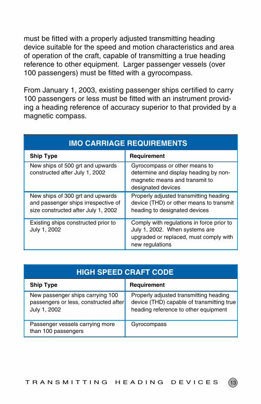
must be fitted with a properly adjusted transmitting headingdevice suitable for the speed and motion characteristics and areaof operation of the craft, capable of transmitting a true headingreference to other equipment. Larger passenger vessels (over100 passengers) must be fitted with a gyrocompass.
From January 1, 2003, existing passenger ships certified to carry100 passengers or less must be fitted with an instrument provid-ing a heading reference of accuracy superior to that provided by amagnetic compass.
Ship Type Requirement
New ships of 500 grt and upwards constructed after July 1, 2002
Gyrocompass or other means to determine and display heading by non-magnetic means and transmit to designated devices
New ships of 300 grt and upwards and passenger ships irrespective of size constructed after July 1, 2002
Properly adjusted transmitting heading device (THD) or other means to transmit heading to designated devices
Existing ships constructed prior to July 1, 2002
Comply with regulations in force prior to July 1, 2002. When systems are upgraded or replaced, must comply with new regulations
Ship Type Requirement
New passenger ships carrying 100 passengers or less, constructed after July 1, 2002
Properly adjusted transmitting heading device (THD) capable of transmitting true heading reference to other equipment
Passenger vessels carrying more than 100 passengers
Gyrocompass
IMO CARRIAGE REQUIREMENTS
HIGH SPEED CRAFT CODE

14 A P R A C T I C A L G U I D E T O
5 CHAPTER 5
Performance StandardsDetailed performance standards for marine GNSStransmitting heading devices are contained in IMOResolution MSC.116 (73) and ISO International Stan-dard 22090-3. The following is a brief summary ofrelevant provisions. Users should refer to the sourcedocuments (see References, page 17) for completeinformation.
• The THD must be capable of continuous operationunder conditions of vibration, humidity and tempera-ture spelled out in detail in ISO 22090-3.
• All displays, with the exception of the sensor, and alloutputs of heading must indicate true heading.
• The THD must have means to align the sensingdirection to the ship’s fore and aft line.
• The THD must be able to maintain the heading accu-racy within ±1.5° for at least 60 seconds if the satellitesignal is interrupted.
• Settling time must be less than 10 minutes under staticconditions.
• The THD must output a new heading at least onceevery 50 ms.
• At least one digital serial output must comply with IEC61162.
• The THD must be equipped with an alarm to indicateTHD malfunction, failure of power supply and continu-ous GNSS signal interruption over 60 seconds at least.
• The transmission error, including the resolution error,must be less than ±2°.
• The static error (settle point error) at any heading mustbe within 1.0°, 95%.

15T R A N S M I T T I N G H E A D I N G D E V I C E S
• The dynamic error must be within 1.5°, 95%.
• The follow-up error for different rates of turn must be:
Less than ±0.5° up to a rate of 10° per secondLess than ±1.5° up to a rate of between 10 and 20° per second
DEFINITIONS
Transmission and resolution error. Error which iscaused by the method used to transmit the original infor-mation to a receiving device. This error is caused by themethod used inside the THD and at its output to code theinformation.
Static Error. Error which is caused by any reason andwhich stays unchanged in value during the operation of thesystem. This error should be measured under staticconditions.
Dynamic Error. Error which is caused by dynamic influ-ences acting on the system, such as vibration, roll, pitch orlinear acceleration. This error may have an amplitude andusually a frequency related to the environmental influencesand the parameters of the system itself.
Follow-up Error. Error which is caused by the delaybetween the existence of a value to be sensed and theavailability of the corresponding signal or data steam at theoutput of the system – for instance, the difference betweenthe real heading of turning vessel and the available infor-mation at the output of the system. The follow-up errordisappears when the system is static.

16 A P R A C T I C A L G U I D E T O
6 A Hybrid SolutionCHAPTER 6
The Sperry Marine NAVISTAR system has been designedto meet the IMO requirement for transmitting headingdevices on new ships 300-500 gross tons, and as a viablelow-cost alternative to spinning-mass and fiber-opticgyrocompasses for workboats, fishing boats, pleasureyachts, naval patrol boats and other smaller vessels notrequired to carry a gyrocompass.
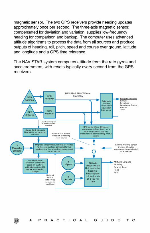
NAVISTAR incorporates a unique “hybrid” design, usingadvanced attitude algorithms to process phase data fromtwo GPS carrier frequencies, together with data from threegyro rate sensors and three accelerometers to provide astable and reliable geographic-north oriented headingreference. In addition to true heading, the system alsooutputs rate of turn, speed over ground and GPS position instandard maritime message formats.
NAVISTAR provides a very high dynamic accuracy andrapid start-up times. The very high update rate makes theNAVISTAR an ideal heading reference for modern adaptiveautopilots.
The system provides eight selectable heading output ports.All output data is provided in industry-standard IEC 61162-1formats suitable for integration into repeaters, radars,autopilots, chart plotters, scanning sonars, AIS, VDR andsteerable antenna arrays.
The system also contains a three-axis magnetic fieldsensor for redundancy and backup. The magnetic fieldsensor is automatically corrected for deviation and variationto provide true heading. An internal compass monitorconstantly compares the GPS solution against the magneticheading sensor. In case of degradation or loss of GPSdata, an audible alarm sounds, and the system automati-

17T R A N S M I T T I N G H E A D I N G D E V I C E S
cally defaults to the internal magnetic compass for uninterruptednavigation.
The NAVISTAR system consists of three primary components: thedual GPS antenna array, the processor unit and the control/displayunit with large, high-resolution LCD screen, plus connecting cables.The system runs on 12-24 VDC power supply and is designed foreasy installation on new or existing vessels. It has no moving partsand is virtually maintenance free. The three rate gyros and acceler-ometers provide angular rate and acceleration data in three planeswith a very high update rate of 100 times per second. They cansupply heading for up to 3 minutes with no reset from the GPS or
Heading Selector & CompassMonitor
Head-Up Compass Card
18 A P R A C T I C A L G U I D E T O
magnetic sensor. The two GPS receivers provide heading updatesapproximately once per second. The three-axis magnetic sensor,compensated for deviation and variation, supplies low-frequencyheading for comparison and backup. The computer uses advancedattitude algorithms to process the data from all sources and produceoutputs of heading, roll, pitch, speed and course over ground, latitudeand longitude and a GPS time reference.
The NAVISTAR system computes attitude from the rate gyros andaccelerometers, with resets typically every second from the GPSreceivers.
19G N S S T R A N S M I T T I N G H E A D I N G D E V I C E S
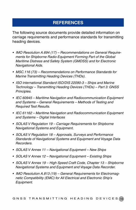
REFERENCES
The following source documents provide detailed information oncarriage requirements and performance standards for transmittingheading devices.
• IMO Resolution A.694 (17) – Recommendations on General Require-ments for Shipborne Radio Equipment Forming Part of the GlobalMaritime Distress and Safety System (GMDSS) and for ElectronicNavigational Aids.
• MSC.116 (73) – Recommendations on Performance Standards forMarine Transmitting Heading Devices (THDs).
• ISO international Standard ISO/DIS 22090-3 – Ships and MarineTechnology – Transmitting Heading Devices (THDs) – Part 3: GNSSPrinciples.
• IEC 60945 – Maritime Navigation and Radiocommunication Equipmentand Systems – General Requirements – Methods of Testing andRequired Test Results.
• IEC 61162 – Maritime Navigation and Radiocommunication Equipmentand Systems – Digital Interfaces
• SOLAS V Regulation 19 – Carriage Requirements for ShipborneNavigational Systems and Equipment.
• SOLAS V Regulation 18 – Approvals, Surveys and PerformanceStandards of Navigational Systems and Equipment and Voyage DataRecorders.
• SOLAS V Annex 11 – Navigational Equipment – New Ships
• SOLAS V Annex 12 – Navigational Equipment – Existing Ships
• SOLAS V Annex 19 – High Speed Craft Code, Chapter 13 – ShipborneNavigational Systems and Equipment and Voyage Data Recorder.
• IMO Resolution A.813 (19) – General Requirements for Electromag-netic Compatibility (EMC) for All Electrical and Electronic Ship’sEquipment.

20 A P R A C T I C A L G U I D E T O
ABBREVIATIONS AND ACRONYMS
AIS ............ Automatic Identification System
ARPA ......... Automatic Radar Plotting Aid
COG .......... Course over Ground
DGPS ........ Differential GPS
ECDIS ....... Electronic Chart Display and Information System
EPA ........... Electronic Plotting Aid
GNSS ........ Global Navigation Satellite System
GPS........... Global Positioning System
IEC ............ International Electrotechnical Commission
IMO ........... International Maritime Organization
ISO ............ International Standards Organization
ROT ........... Rate of Turn
RTCM ........ Radio Technical Commission for Maritime Services
SOG .......... Speed over Ground
SOLAS V ... Safety of Life at Sea Convention, Chapter V
THD ........... Transmitting Heading Device
VDR........... Voyage Data Recorder
21G N S S T R A N S M I T T I N G H E A D I N G D E V I C E S
USEFUL LINKS
www.sperrymarine.northopgrumman.com – Sperry Marine
www.navcen.uscg.gov – U.S. Coast Guard Navigation Center
www.imo.org – International Maritime Organization
www.iec.ch – International Electrotechnical Commission
www.mcagency.org.uk – Marine and Coastguard Agency
www.seamanship.co.uk – Seamanship International

© 2005 Northrop Grumman BR0111 • XM • 12/03/05 Printed In The U.S.A.
Sperry Marinewww.sperrymarine.northropgrumman.com