ijsrd || conference on mechanical engineering &technology
TRANSCRIPT

IJSRD || Conference on Mechanical Engineering &Technology (COMET) || January 2016 || ISSN:2321-0613
©IJSRD 2016 Published by IJSRD 25
Autonomous Domestic Locomotion Vehicle -
“Intelliwheelz” Wheelchair
Nehal Dash
Department of Mechanical Engineering
Birla Institute of Technology, Jharkhand, India
Abstract— In this modern world, automation has become the basic purpose for any new device. Sensors always make us a
step closer towards automation and thus sensors have been an integrated part of the human life these days. Any small device
or fully automated equipments, irrespective of the field of application, requires the use of sensors that allows the individuals
to meet their demands. MEMS has been a super sensor these days. In most of the devices and equipments, MEMS act as an
effective integration as per requirements. In country like India where 2.1% of population is suffering from chronic mobility
impairment, it was a thought to integrate MEMS along with some other modules into a domestic locomotive vehicle. This
MEMS and sensor based domestic locomotive vehicle is a wheelchair namely “IntelliWheelZ‟ that provides the differently
able people with a solution for autonomous locomotion both at indoor and outdoor conditions. IntelliWheelZ is a low cost
multi-module battery operated autonomous wheelchair with simple user friendly ergonomics. IntelliWheelZ consists of four
modules. Firstly, Micro Electro Mechanical Sensor (MEMS) is best suited for those kind of disable people who have any
one working joint in their body. Secondly, Voice Recognition system allows the wheel chair to move on the basis of voice
command fed into it as per requirement. Remote Control System is the third module that controls the motion of wheel chair
through switches of a remote controlled device on the principle of remote sensing and relay circuit. The final module of the
wheel chair is the Obstacle Sensing and Detection Mechanism that senses and detects the obstacle on the path and avoids the
wheel chair from accidents. Incorporating all these modules the total expenditure of IntelliWheelZ is less than 10% of the
cost of autonomous wheel chairs presently available in the market. Hence the autonomous mobility and its low cost allow us
to say: “IntelliWheelZ‟ – A MEMS based multi module low cost Autonomous Wheel Chair for effective domestic
locomotion.
Key words: MEM Sensor, Electromyogram Signals, Voice Recognition System, Obstacle sensing & Detection Mechanism
and Autonomous Navigation using Remote Control System
I. INTRODUCTION
The design and implementation of a sensor and control system to support the user of an automated mechanical-electrical
(Electromechanical) MEMS and sensored based wheelchair with respect to navigation and obstacle detection has been the
objective of the “IntelliWheelZ”. This includes realization of functionalities like
A MEMS based Autonomous wheel chair provides a firm solution to the most common form of disability i.e the
disability in movement, by allowing the differently able persons to move independently from one place to other both at indoor
and outdoor conditions.
Autonomous control of the electric wheelchair with the help of body joint movements by the MEMS and other smart
sensors.
Reliable avoidance of obstacles, including concave obstacles, like descending stairs or holes,
The main objective behind creating the working model of the project was to make a compact and easy to operate
product for disables.
Information of the nursing staff or helpers in case of emergency on the vehicle´s location and characteristic parameters.
The aim is to increase this way the capabilities for mobility also for severely handicapped people as well as the safety
of transports. Like every project we took into consideration the cost so that it would be an affordable product in the society.
Our continuous endeavor in the project was to produce a final working model of a low cost autonomous wheel chair –
IntelliWheelZ with multiple modules integrated into it.
A. Additional Features
The turning radius of IntelliWheelZ is less than 600 mm (24 inches approx). If the turning radius is less, we can take U-turn
easily with single attempt. Otherwise we will have to reverse and forward several times to negotiate the U-turn.
Depending upon the study made and the hit and trial methods, we decided to go with a pair of spur gears with a velocity
ratio of 1:5 that is number of teeth being 16 and 80 respectively.
B. Problem Statement
New-generation, intelligent, powered wheelchairs promise to increase the mobility and freedom of individuals with serious
chronic mobility impairments. And while rapid progress continues to be made in terms of the engineering capabilities of robotic
wheelchairs, many projects fall short of the target in terms of ease of use, conviviality, robustness and safety. This paper

Autonomous Domestic Locomotion Vehicle -“Intelliwheelz” Wheelchair
(IJSRD/Conf/COMET/2016/005)
26
describes the “IntelliWheelZ”, a multifunctional sensor based intelligent wheelchair, which uses the present available
technology and compiling them for both autonomous navigation and user interaction modeling, to provide a new robust, safe
and cheap solution to the problem of assistive mobility with a new output system generation which is unique in its final solution.
II. INTRODUCTION
We found that about 2.1% of the total population in India is suffering from any one or other kind of disability. Also we came
to know that out of these different disabilities, the most common type of disabilities are found in order of disability in movement,
mental disorders, speech disorders and finally disability in hearing. Our project, „IntelliWheelZ – An Autonomous(sensor
based) wheel chair provides a firm solution to the most common form of disability i.e the disability in movement, by allowing
the differently able persons to move independently from one place to other both at indoor and outdoor conditions.
MEMS is the first module of IntelliWheelZ. This MEMS is best suited for those kind of disable people who are able
to move only one joint in their body as in the neck muscles, any hand or leg finger joints, wrist joint, arm joint etc. Any one of
the working joint in the whole body will allow the person to move in this wheel chair with MEMS module. The basic use of
this sensor is used as accelerometer and motion sensors in embedded mobile applications. MEMS 3-axis accelerometer consists
of mass at centre of the chip, which is suspended by beams doped with piezo resistive material. When the sensor is subjected
to acceleration in any direction, the movement of mass causes the beam to deform and so change the resistance in the piezo
material enables the sensor to detect the accelerated motion.
Voice Recognition system allows the wheel chair to move on the basis of voice commands. In this VR system 99 voice
commands can be fed as per requirement like left, right, stop etc. in any language. It shows relevant output once the input is
provided into it which in turn moves the wheel chair in the required direction as per the input command. We have used HM-
2007 VR kit in IntelliWheelZ. This is a step ahead of the applications found in automobile stereo systems which work on the
basis of voice commands.
Remote Control System allows the motion of wheel chair through a remote controlled device on the principle of remote
sensing and relay circuit with the help of RC5 codes. It has switches for the movement in directions like forward, backward etc.
making the wheel chair respond to the input provided.
The last module of the wheel chair is the Obstacle Sensing & Detection Mechanism through smart sensors. An obstacle
sensor is fit in the wheel chair that senses and detects the obstacle on its way and stops the wheel chair from accidents whenever
required, making the safety of the person sitting on wheel chair as its prime objective.
IntelliWheelZ has four different modules which form an integral part of it. The four modules are Micro Electro
Mechanical Sensor (MEMS), Voice Recognition System, Remote Control System and Obstacle Sensing & Detection
Mechanism. All these modules receive the input independently and provide us with the output as per requirement. IntelliWheelZ
has a power supply from a 12V battery that provides the relevant power supply to it.
In addition to its autonomous mobility through these modules other important features of IntelliWheelZ are its low
cost, simple ergonomics and easy dismantable modules. The cost of it is about Rs 20000/- which is less than 10% of the
autonomous wheelchairs available in present market scenario.
Looking at the fact that in country like India the percentage of disability in movement is more and is still increasing,
IntelliWheelZ – A MEMS based autonomous wheel chair, constituting of integrated modules and features make it a solution to
this problem.
III. MATERIAL SELECTION OF “INTELLIWHEELZ‟
The materials which were analyzed are aluminium, cast iron, mild steel, abs etc. We selected these materials because of their
easy availability and their common applications in manufacturing industries. We have studied the properties of these materials
to fulfill the requirement of the project. As aluminium is known for its light weight and rust free nature but according to our
project we need material that has high yield strength and hardness, easy to weld together. So we came up with mild steel as best
material for our project.
IV. DESIGNING AND MODELLING OF “INTELLIWHEELZ‟
A. Design Calculations
For the designing of IntelliWheelZ we have considered several parameters and performed the relevant calculations to determine
the appropriate results. These calculations include the DC motors selection both at inclined and horizontal surfaces, Effective
propulsion method to calculate the percentage weight on wheels, turning radius determination followed by the velocity
reduction mechanism by spur gear drive.
1) Selection of DC Motors
For choosing the DC Motors we have done theoretical study that helped us to select the relevant type and size of DC Motors.
Predefined parameters for calculations:
Mass of wheelchair = M wheelchair = 150kg
(This mass includes both the mass of the wheelchair and the person sitting on it assumed to be 70kg and 80kg respectively.)
Gravitational acceleration = g = 9.81m/s2 Maximum angle of inclination = 37o [15] Coefficient of friction = µ = 0.5
to 0.7
(We have chosen µ = 0.7, for worst possible condition)
Wheel Radius = r = 5cm =0.05mm
Autonomous Domestic Locomotion Vehicle -“Intelliwheelz” Wheelchair
(IJSRD/Conf/COMET/2016/005)
27
Wheel perimeter = P wheel = 2πr = 0.314m Assuming the required acceleration = ax = 1m/s2
Average velocity of wheelchair = V average = 5km/h = 1.39m/s
a) Horsepower calculation for horizontal surface
The wheelchair on an approx will be spending a large amount of time it runs on horizontal surfaces. Hence it is needed to be
provided with most importance while determining the horsepower of motor on these surfaces.
Combine weight of IntelliWheelZ,
W = M × g = 150 × 9.81 = 1471.5 N (let say)
Reaction of the incline, R = W = 1471.5 N
Friction force, ƒx = μmax × R = 0.7 × 1471.5 = 1030 N
At equilibrium, ΣFx = F - ƒx = 0
F= ƒx = 1030 N (min value) Also,
ΣFx = M × ax = F - ƒx - Wx F = (150 + 1030) N
Propulsion force F = 1180 N (max value)
Torque at the wheel,
T = F × r = 1180 × 0.05 = 59 N.m = 43.365 lb-ft.
Velocity, V = 5000/ 60 = 83.33 m/min Calculation of rpm = V/ Perimeter of wheel = 265.38 rpm
HP = (T*rpm)/5252;
= (43.365* 265.38)/5252
= 2.1912 HP.
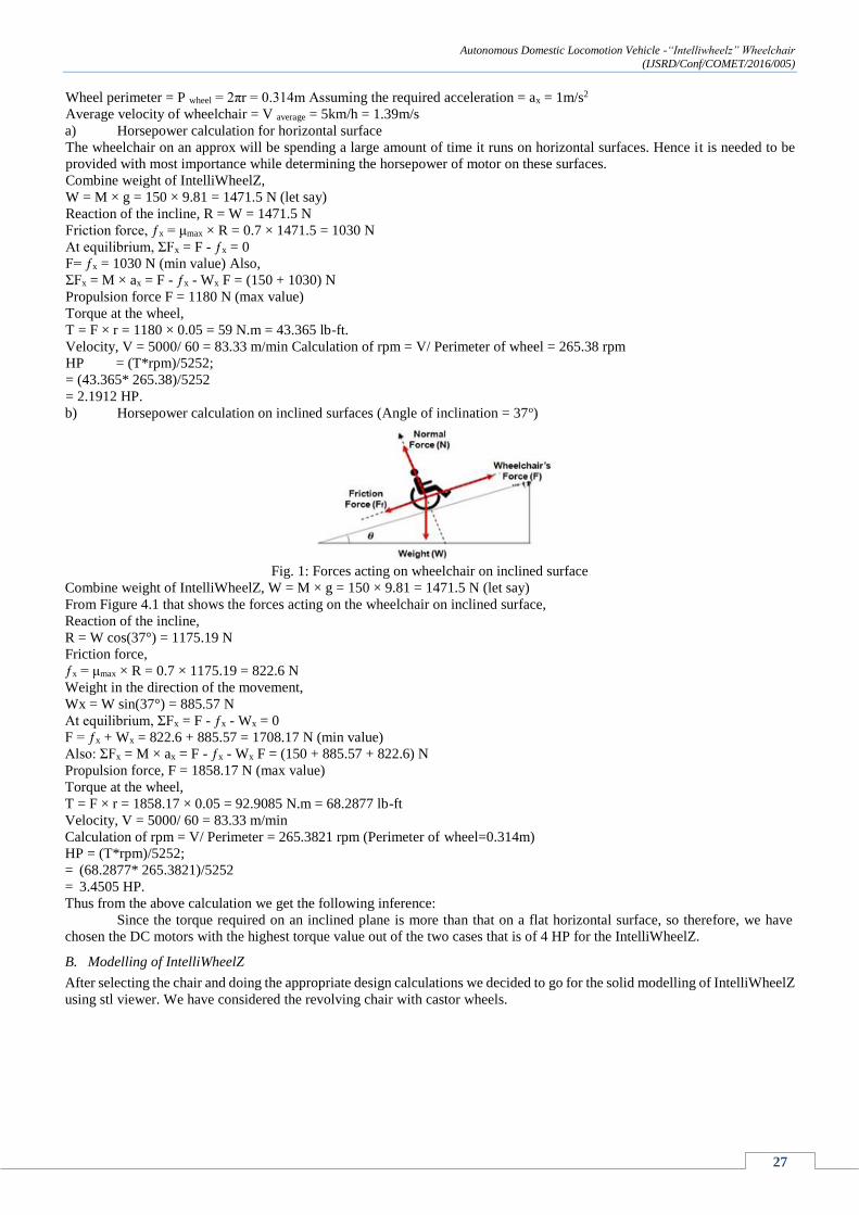
b) Horsepower calculation on inclined surfaces (Angle of inclination = 37o)
Fig. 1: Forces acting on wheelchair on inclined surface
Combine weight of IntelliWheelZ, W = M × g = 150 × 9.81 = 1471.5 N (let say)
From Figure 4.1 that shows the forces acting on the wheelchair on inclined surface,
Reaction of the incline,
R = W cos(37°) = 1175.19 N
Friction force,
ƒx = μmax × R = 0.7 × 1175.19 = 822.6 N
Weight in the direction of the movement,
Wx = W sin(37°) = 885.57 N
At equilibrium, ΣFx = F - ƒx - Wx = 0
F = ƒx + Wx = 822.6 + 885.57 = 1708.17 N (min value)
Also: ΣFx = M × ax = F - ƒx - Wx F = (150 + 885.57 + 822.6) N
Propulsion force, F = 1858.17 N (max value)
Torque at the wheel,
T = F × r = 1858.17 × 0.05 = 92.9085 N.m = 68.2877 lb-ft
Velocity, V = 5000/ 60 = 83.33 m/min
Calculation of rpm = V/ Perimeter = 265.3821 rpm (Perimeter of wheel=0.314m)
HP = (T*rpm)/5252;
= (68.2877* 265.3821)/5252
= 3.4505 HP.
Thus from the above calculation we get the following inference:
Since the torque required on an inclined plane is more than that on a flat horizontal surface, so therefore, we have
chosen the DC motors with the highest torque value out of the two cases that is of 4 HP for the IntelliWheelZ.
B. Modelling of IntelliWheelZ
After selecting the chair and doing the appropriate design calculations we decided to go for the solid modelling of IntelliWheelZ
using stl viewer. We have considered the revolving chair with castor wheels.

Autonomous Domestic Locomotion Vehicle -“Intelliwheelz” Wheelchair
(IJSRD/Conf/COMET/2016/005)
28
Fig. 4.2 (a): Right Side View Fig. 4.2 (b): Left Side View
Fig. 4.2 (c): Front Side View Fig. 4.2 (d): Back Side View
Fig. 4.12(e): Top View Fig. 4.2 (f): Bottom View
Fig. 4.2(g): Extruding through axes Fig. 4.2(h): Extruding through axes
V. MODULES OF “INTELLIWHEELZ‟
A. Micro Electro Mechanical Sensor (MEMS)
Micro Electro Mechanical Sensor (MEMS) which is best suited for those kind of disable people who have any one working
joint in their body. MEMS is the first module of IntelliWheelZ. MEMS 3-axis accelerometer consists of mass at centre of the
chip, which is suspended by beams doped with piezo-resistive material. When the sensor is subjected to acceleration in any
direction, the movement of Mass causes the beam to deform and so change the resistance in the piezo material. This enables
the sensor to detect the accelerated motion. Hence this explains the basic working principle of MEMS.

Autonomous Domestic Locomotion Vehicle -“Intelliwheelz” Wheelchair
(IJSRD/Conf/COMET/2016/005)
29
Fig. 5.1: Basic Working Principle of MEMS
Considering the above figure 5.1, it consists of a proof mass (M), hold by a spring with spring constant k and is
connected to a dashpot with damping coefficient (C). When the sensor is deflected in any particular direction, the acceleration
produced by the flow of proof mass is directly proportional to the deflection caused in the sensor and thus produces an equivalent
amount of motion in the respective direction.
We know that,
Acceleration Force F a = M*a, (1)
(Where, m = proof mass and a = acceleration caused by the deflection of the sensor).
Also,
SpringForce,Fs= k*x - (2)
(Where, k = spring‟s constant and x = motion caused by the deflection of MEMS).
By comparing, equation (1) and (2), we get
F a = F S
Thus,
M*a=k*x - (3)
Hence, from equation (3), we can say that acceleration produced by the flow of proof mass by the deflection of the
sensor is directly proportional to the amount of motion produced in the respective direction, that is, a α x.
MEMS consist of suspended beams arranged in the form of parallel plate capacitor. In-plane accelerometers use a set
of fixed electrodes and moveable electrodes as shown in figure 5.2. The moveable electrodes are part of a “proof mass” that
moves linearly with acceleration or deceleration. The single pair of capacitor consists of one fixed beam and one sense beam
or finger. The deflection produced in the sensor by the flow of proof mass in turn produces a simultaneous motion in the sensing
figure of the parallel plate capacitors. This changes the capacitance of the capacitor which in turn produces an instant motion
output thereby driving the wheel of the chair.
Fig. 5.2: Electrical Working Concept of MEMS
Initially we tested this module by fixing it into a four wheel small robot. We were successful in the test by fixing
MEMS at different locations of body joint like the neck, the fingers of hand etc. and hence this success gave us an upper hand
to incorporate this mechanism into the prototype. Hence in the final prototype we have given a constrained position to MEMS
by fixing into the hand segment of the wheelchair. The following Figure 5.3 shows the MEMS circuit board of IntelliWheelZ.

Autonomous Domestic Locomotion Vehicle -“Intelliwheelz” Wheelchair
(IJSRD/Conf/COMET/2016/005)
30
Fig. 5.3: MEMS Circuit Arrangement
1) Algorithm for MEMS Module:
The MEMS module used in wheelchair has four comparators, paired into two as X and Y group comparators respectively. The
directional input that is provided by the tilting of the MEMS is given to the comparator loop. The X group comparator denotes
the forward (X+) and reverse (X-) direction. Similarly the Y group comparators denote the right (Y+) side and left (Y-) side
directions respectively, this in turn gives the final output to the driving circuit as per the input signal provided to the comparator
assigned for motion in that direction. This algorithm of MEMS explained above is depicted in figure 5.4 below.
Fig. 5.4: Algorithm for MEMS
B. Voice Recognition System (VR System)
Voice Recognition system allows the wheel chair to move on the basis of voice command fed into it. In this VR system 99
voice commands can be fed as per requirement like left, right, stop etc. in any language. It shows relevant output once the input
is provided into it which in turn moves the wheel chair in the required direction as per the input command. We have used HM-
2007 VR kit in IntelliWheelZ. This is a step ahead of the applications found in automobile stereo systems which work on the
basis of voice commands.
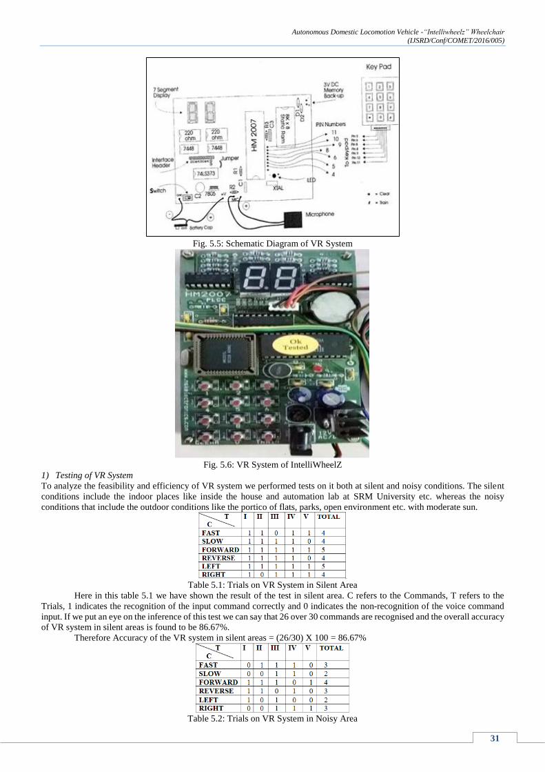
For incorporating the VR system Pre-program Microcontroller (HM 2007) is used. This microcontroller takes the voice
command chopping into slices. The slices are then sampled with the existing data stored in ram. If sample matches with existing
data, output is achieved. This output achieved is shown in the display board corresponding to the saved digital inputs. This
system provides binary outputs. Speaker dependent and speaker independent modules are also available in HM2007. The
Schematic diagram of VR system is shown below in figure 5.5 and the final VR system is shown in figure 5.6.
Autonomous Domestic Locomotion Vehicle -“Intelliwheelz” Wheelchair
(IJSRD/Conf/COMET/2016/005)
31
Fig. 5.5: Schematic Diagram of VR System
Fig. 5.6: VR System of IntelliWheelZ
1) Testing of VR System
To analyze the feasibility and efficiency of VR system we performed tests on it both at silent and noisy conditions. The silent
conditions include the indoor places like inside the house and automation lab at SRM University etc. whereas the noisy
conditions that include the outdoor conditions like the portico of flats, parks, open environment etc. with moderate sun.
Table 5.1: Trials on VR System in Silent Area
Here in this table 5.1 we have shown the result of the test in silent area. C refers to the Commands, T refers to the
Trials, 1 indicates the recognition of the input command correctly and 0 indicates the non-recognition of the voice command
input. If we put an eye on the inference of this test we can say that 26 over 30 commands are recognised and the overall accuracy
of VR system in silent areas is found to be 86.67%.
Therefore Accuracy of the VR system in silent areas = (26/30) X 100 = 86.67%
Table 5.2: Trials on VR System in Noisy Area

Autonomous Domestic Locomotion Vehicle -“Intelliwheelz” Wheelchair
(IJSRD/Conf/COMET/2016/005)
32
Here in this table 5.2 we have shown the result of the test in noisy area. C refers to the Commands, T refers to the
Trials, 1 indicates the recognition of the input command correctly and 0 indicates the non recognition of the voice command
input. If we put an eye on the inference of this test we can say that 17 over 30 commands are recognised and the overall
accuracy of VR system in noisy areas is found to be 56.67%.
Therefore Accuracy of the VR system in noisy areas = (17/30) X 100 = 56.67%
2) Construction of control chart for performance analysis of VR system
On the basis of above two conducted tests we constructed control charts for the performance analysis of VR system. In this
control chart, shown in the Figure 5.7 the X axis indicated the Commands and the Y axis indicated the number or quantity of
correct outputs shown by it.
Fig. 5.7: Control Chart of Performance Analysis of VR System Inference from above test on VR system
The frequency of recognizable commands in silent areas like home, office etc. is comparatively much higher than that
of the noisy areas like the street environment or in parks.
Steps to improve the accuracy of the VR Kit in noisy areas
The HM2007 VR Kit can be placed at the hand rest of the chair to reduce the acoustical disturbances.
Collar mike can be added to the kit so that the voice frequency of the user can be easily captured and processed.
Note: These steps not only increase the accuracy of the VR Kit in noisy areas but simultaneously, if implemented in silent areas
would yield the equivalent increase in recognizable commands in silent areas too.
C. Remote Control System Module
Remote Control System is the third module of IntelliWheelZ that controls the motion of wheel chair through switches of a
remote controlled device on the principle of remote sensing and relay circuit with the help of RC5 codes. It has switches for the
movement in directions like forward, backward etc. making the wheel chair respond to the input provided.
It consists of 4 switches to carry out 4 different operations of forward, reverse, right and left respectively where as
more switches can also be added into this system to operate other functions like emergency stop, horn etc. as shown in the
figure 5.8. It consists of a microcontroller which acts as an encoder for RC5 type signal interfacing. Driver circuit consists of
decoder micro-controller which decodes the input signal and gives the output to the driving circuit.
The encoded signal from the remote control antenna is received by the four slave relays of the remote control circuit
itself. This in turn gives the signal to the pair of slave relays associated with the driving circuit. From these slave relays the final
signal is given to the main relay circuit which has six relays in it for forward, backward, right, left, emergency stop and time
delay circuit. The input and output signals of remote control system is in the form of decimal signals.
This remote control provides a platform for synchronization of all the modules with the help of single interfacing
circuit that is the remote control circuit itself.
Fig. 5.8: Remote Control System Circuit Arrangement
D. Obstacle Detection Mechanism
The final module of the wheel chair is the Obstacle Sensing and Detection Mechanism that senses and detects the obstacle on
the path and avoids the wheel chair from accidents. An obstacle sensor is fit in the wheel chair that senses and detects the
obstacle on its way and stops the wheel chair from accidents whenever required, making the safety of the person sitting on
wheel chair as its prime objective. It consists of a transmitter and a receiver in it. The transmitter transmits the data that is the
IR signals if any obstacle is detected then the IR rays reflects back which is received by the receiver and sends the output to
switch off the motors. It is fixed at the most forward position of the wheelchair so that it works effectively. It detects the obstacle

Autonomous Domestic Locomotion Vehicle -“Intelliwheelz” Wheelchair
(IJSRD/Conf/COMET/2016/005)
33
at an approximate distance of about 500mm to 600mm. We tested IntelliWheelZ with two kinds of obstacle sensors shown in
figure 5.9 and decided to go with the best one out of both for better performance. Apart from this UV sensors can also be fit
into this wheelchair to achieve even better performance, whereas the mechanism to fit is exactly the same as the one we have
incorporated at present.
Fig. 5.9: Obstacle Sensors 5.5 Selection of Battery
We have selected a 12V Lead Tin Acid battery based on our calculations and power requirement of the dc motor
shown in figure 5.10. This battery has been selected keeping in mind the battery discharge and charging characteristics, effective
compatibility and light weight as compared to the other available batteries. The battery is fixed in the electric circuit board
segment that is placed at the base chassis of the wheelchair.
Performance specifications of Battery
Nominal Voltage (V) = 12 volts Nominal Capability (Ah) = 20 Ah
= 20 hour rate F.V (1.75 V/Cell) (1000mA to 10.50 volts)
Approximate Weight = 1.75 kg
Dimension of Battery
Length = 150 mm Width = 100 mm
Container height = 75 mm Total height = 75 mm
Some other applications of this battery are UPS, Fishing lights, Emergency lights etc.
Fig. 5.10: Battery Used In IntelliWheelZ
VI. CIRCUIT AND SYNCHRONIZATION OF INTELLIWHEELZ
A. Synchronization of Modules
The synchronization of these modules together into a single unit is the most important step in this project. The easy and smooth
synchronization of all modules leads to better and efficient output. Hence we decided that the best part of making it simple was
to provide inputs of all the modules through a single module.
Considering the remote control system as the base and primary module to provide the inputs of all the other modules,
we tried to synchronize the inputs of all other modules to the remote control system. In the process of doing so at first we
synchronized the MEMS module with the remote control system. The output signal from the MEMS activated the corresponding
switch of the remote control system. Similarly we have done the same for the VR system. In case of VR system we also needed
to add an additional circuit of binary to decimal converter as we knew that the output of the VR system is in binary form and
the remote system accepts the input in decimal form only. Hence in doing so we successfully synchronized all the modules of
IntelliWheelZ through the remote control system. The Synchronized hand segment is shown in figure 6.1 below.
Autonomous Domestic Locomotion Vehicle -“Intelliwheelz” Wheelchair
(IJSRD/Conf/COMET/2016/005)
34
Fig. 6.1: Synchronized Hand Segment of IntelliWheelZ
In the flowchart below figure 6.2, we have depicted the synchronization of all the modules of IntelliWheelZ using the
remote control system.
Fig. 6.2: Synchronization of all Modules of IntelliWheelZ
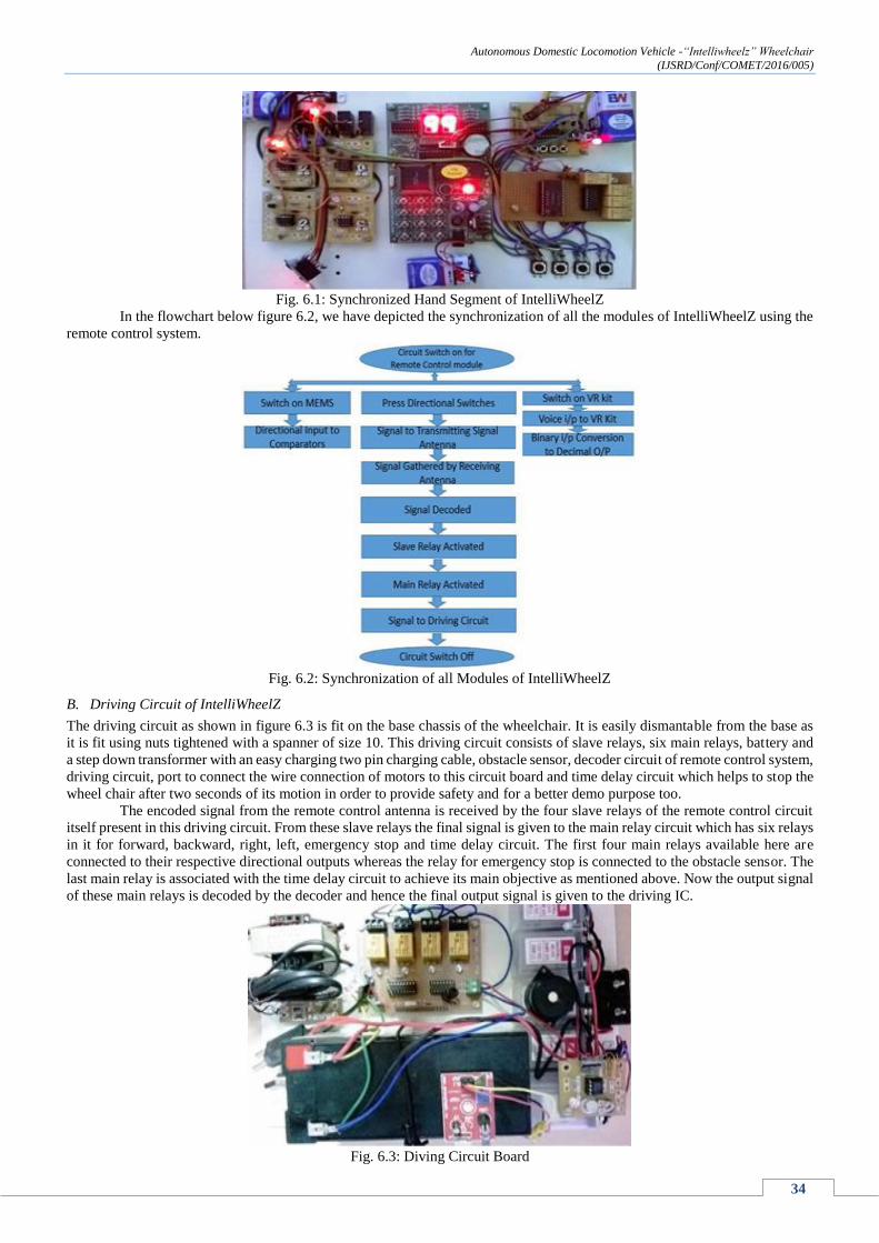
B. Driving Circuit of IntelliWheelZ
The driving circuit as shown in figure 6.3 is fit on the base chassis of the wheelchair. It is easily dismantable from the base as
it is fit using nuts tightened with a spanner of size 10. This driving circuit consists of slave relays, six main relays, battery and
a step down transformer with an easy charging two pin charging cable, obstacle sensor, decoder circuit of remote control system,
driving circuit, port to connect the wire connection of motors to this circuit board and time delay circuit which helps to stop the
wheel chair after two seconds of its motion in order to provide safety and for a better demo purpose too.
The encoded signal from the remote control antenna is received by the four slave relays of the remote control circuit
itself present in this driving circuit. From these slave relays the final signal is given to the main relay circuit which has six relays
in it for forward, backward, right, left, emergency stop and time delay circuit. The first four main relays available here are
connected to their respective directional outputs whereas the relay for emergency stop is connected to the obstacle sensor. The
last main relay is associated with the time delay circuit to achieve its main objective as mentioned above. Now the output signal
of these main relays is decoded by the decoder and hence the final output signal is given to the driving IC.
Fig. 6.3: Diving Circuit Board

Autonomous Domestic Locomotion Vehicle -“Intelliwheelz” Wheelchair
(IJSRD/Conf/COMET/2016/005)
35
VII. FRUGAL INNOVATION AND LEAN MANUFACTURING
In the whole process of fabrication and doing of project we always kept in mind the science of frugal innovation and lean
manufacturing. This helped us in reducing the cost of products to be used in the wheelchair at various stages of fabrication.
The chair of IntelliWheelZ, is a normal revolving chair, which was chosen and changes were incorporated as required.
Motors used are the wiper motors of automobiles whose winding is changed to meet our requirements. Synchronization of all
modules was done through the remote control system which made the task easy, smooth and was also cost effective. Also we
tried our best to minimize the scrap at every stages of fabrication process.
VIII. SPECIFICATIONS OF INTELLIWHEELZ
Parameters Details
Armrest Height 240 mm
Seat Height 470 mm
Eye Level Height 1090 mm - 1295 mm
Overall Width 535 mm
Overall Length 1000 mm
Chassis Dimension 630 mm x 300 mm
Seat Width 450 mm
Seat Length 430 mm
Main Wheel Inner Diameter 100 mm
Main Wheel Outer Diameter 190 mm
Battery Specifications 12V Lead Tin and 20 Ah
Motors 4 HP Servo
Chair Type Revolving chair with four Castor Wheels
Chair Frame Material ABS material
Suspension Type Hydraulic Suspension
Velocity Ratio/Gear Ratio 1:5
Gear Shaft Diameter 30 mm
Bearings used Pedestal Bearing/Plummer Block
Gears Used Spur Gears
Table 8.1: Specifications of IntelliwheelZ
IX. RESULTS AND PERFORMANCE CHECKING
A. Quality Function Deployment and House of Quality for IntelliWheelZ
Quality Function Deployment (QFD) is defined as development of design of product as per the voice of the customers,
translating the customers‟ expectations and requirements into the design targets keeping in mind the quality assurance in all the
phases of fabrication, designing and production. House of quality (HOQ) is a tool for QFD.
Steps to prepare House of Quality (HOQ)
Step 1: List out the voice of customers that is WHATs.
Step 2: List out the designing requirement/technical voice that is HOWs.
Step 3: Construct the interrelationship matrix between the WHATs and HOWs.
Step 4: Construct the relationship matrix between the HOWs.
Step 5: Do the competitive analysis. Step 6: List out the prioritization matrix.
We have taken major steps to prepare the HOQ. This HOQ (Figure 9.1) is prepared in a conference conducted by the
Confederation of Indian Industries (CII), in presence and assistance of different manufacturers of wheelchair as well as the
design and manufacturing heads of CII at WABCO India on 1st February 2014.
Various customers‟ requirement (WHATs) taken into consideration for constructing this HOQ are Adjustable arm and
foot rest, Improved backrest, improved braking design, improved suspension, less weight etc. The Design requirements (HOWs)
are change of materials, ergonomic design, safety, functionality etc.

Autonomous Domestic Locomotion Vehicle -“Intelliwheelz” Wheelchair
(IJSRD/Conf/COMET/2016/005)
36
Fig. 9.1: HOQ for IntelliWheelZ
B. Testing and Performance Analysis of IntelliWheelZ
As seen from earlier data all the corrections were made and the prototype was ready for the test under various conditions. As
we have seen from the specifications of IntelliWheelZ it can carry weight of the person roughly in the range of 60 kg to 100 kg
along with the weight of the chair which is approximately 40 kg.
To check the proper functioning of IntelliWheelZ we have conducted various analysis tests like easy mobility testing,
wheel clearance testing, function tests of various modules independently and as a collective unit as well. Feedback analysis
from testing and control was also performed.
1) Mobility Test
In the process of mobility testing we had a thorough testing on easy and smooth mobility of wheelchair. This was a continuous
test for a period of more than 10 days where random people with different weights. During this test the feedbacks of the users
were also noted which were positive. No sudden or immediate laps in mobility of IntelliWheelZ were noted in this test, which
no doubt made this test a successful one. Although we noted that proper greasing and oiling of gear drive at regular intervals
would reduce friction leading to better mobility. Another valid point we concluded from this test is that we can also fix the
revolution of the wheelchair about its own axis for even better results.
2) Wheel Clearance Test
There is a clearance of approximately 10 mm on either side of tyre and the frame. However, the tyre was initially contacting
with the cylindrical DC motor which were then tilted slightly with the help of angular linkages welded together seeking help
from pedestal block. After this minor modification, a clearance of around 10 mm was obtained between the cylindrical motors
and the tyre. As it can be seen from the below figure 9.2 the tyre is in direct contact with the driving shaft maintaining the
clearance of 10 mm. This provided a stable support to the wheel without any interference.
Fig. 9.2: Ground Clearance of IntelliWheelZ

Autonomous Domestic Locomotion Vehicle -“Intelliwheelz” Wheelchair
(IJSRD/Conf/COMET/2016/005)
37
3) Functional Tests of all modules of IntelliWheelZ
In this test we paid attention towards the proper functioning of modules independently and as a collective unit as well. At first
we carried out the test for MEMS module in a small robot as an independent module test. In this we placed the sensor at various
joints of body like the neck joint, fingers of the hand and leg etc. With the positive feedbacks of proper functioning we made
this module suitable for the prototype model.
Secondly to test the VR system many random users were chosen to install their voice commands in any language or
code. After successful installation of the voice commands the output accuracy was analyzed. Also we have conducted trial tests
through VR system alone as a medium of locomotion of wheelchair at several locations. The Remote control system being the
main base of all modules was also tested both at indoor and outdoor locations to test the frequency and range of antenna. At
this stage the testing of synchronized form of locomotion through all modules was also carried out.
To read the performance of the obstacle sensor and detection mechanism, obstacles were place at relevant range
distances and the working of sensor was verified. At all the instances wherever the obstacles were placed the wheelchair stopped
as per the range of the obstacle sensor.
C. Cost Analysis of IntelliWheelZ
From a market survey, we came to know that in current market scenario the cost of normal manual wheelchairs is about Rs
18000/- as shown in Figure 9.3.
Fig. 9.3: Cost of Manual Wheel Chair at present
Also we came to know that the price of powered wheelchair with just a joystick module starts at a price of about Rs
250000/- as shown in Figure 9.4.
Fig. 9.4: Cost of Powered Wheelchair
In case of IntelliWheelZ
Cost of IntelliWheelZ including all its four modules is about 10% of the powered wheel chairs presently available in
the market that is around Rs 20000/-. Table 9.1 below illustrates the cost analysis of IntelliWheelZ with presently available
wheelchairs. This fact makes IntelliWheelZ a low cost autonomous wheelchair with multiple modules. Figure 9.5 shows the
Final Model of IntelliWheelZ.
Materials Costs ( ₹ )
Revolving chair 2,000
Wiper motor 1,500
MEMS 1,200
VR Kit 3,900
Remote control 500
Obstacle sensor 700
Main wheels 700
Spur Gear 500
Circuit fabrications 4,000
Welding expenses 200
Chassis and bearings 1,100

Autonomous Domestic Locomotion Vehicle -“Intelliwheelz” Wheelchair
(IJSRD/Conf/COMET/2016/005)
38
Accessories (spanner, washers, 500 nuts, bolts, cutter, etc.) 500
Miscellaneous cost 3,000
TOTAL 19,800
Table 9.1: Cost Analysis of IntelliWheelZ
Type of Wheel Chair Cost
Manual Wheel chair Rs 18500
Powered Wheel chair Rs 256000
IntelliWheelZ Rs 20000
Table 9.2: Cost Analysis
Fig. 9.5: IntelliWheelZ – Final Model
X. CONCLUSION
Our project, IntelliWheelZ – An Autonomous wheel chair provides a firm solution to the most common form of disability i.e
the disability in movement, by allowing the differently able persons to move independently from one place to other both at
indoor and outdoor conditions. The main objective behind creating the working model of the project was to make a compact
and easy to operate product for disables.
Like every project we took into consideration the cost so that it would be an affordable product in the society. Our
continuous endeavor in the project was to produce a final working model of a low cost autonomous wheel chair – IntelliWheelZ
with multiple modules integrated into it. Looking at the fact that in country like India the percentage of disability in movement
is more and is still increasing, IntelliWheelZ – An autonomous wheel chair, constituting of integrated modules and features
make it a feasible solution to this problem.
The four modules of IntelliWheelZ that is the MEMS, VR System, Remote Control System and Obstacle Sensing and
Detection Mechanism all together constituting the integral part of wheel chair, allow it to move automatically as per the input
provided in respective modules, which makes this wheel chair an autonomous wheel chair namely IntelliWheelZ. Incorporating
all these modules the total expenditure of IntelliWheelZ is less than 10% of the cost of autonomous wheel chairs presently
available in the market scenario.
Hence from the above facts we can conclude saying „IntelliWheelZ‟ – A low cost Autonomous Wheel Chair with
multiple modules.
XI. FUTURE SCOPE OF THE PROJECT
As the project is successful and cheap also many improvements can be done to increase its demand in the present scenario. The
following improvements can be made
Base can be redesigned in order to provide a more customized foot rest.
Arrangement can be made for self on board charging of battery.
A high range of obstacle sensor can be used for better obstacle sensing and detection.
Worm and worm gear drive can be used to avoid drive reversal.
Efficiency of the VR system can be improved by placing the mike at closer distance to the command source.
Ergonomics of the wheel chair can be further improved and customized as per the disability.
Rotating motion of the sitting platform of wheelchair can be restricted

Autonomous Domestic Locomotion Vehicle -“Intelliwheelz” Wheelchair
(IJSRD/Conf/COMET/2016/005)
39
REFERENCES
[1] Govt. of India, Ministry of Home Affairs, ‟our census our future‟‟.
[2] Movea use of MEMS motion sensor for embedded mobile apps by Bruno Flament
[3] South west centre for micro system, MEMS 102, Micro system work by SCME.
[4] VR system Data sheet.
[5] Volkswagen stereo system, wikipedia
[6] RC 5 codes, Wikipedia
[7] www.healthkart.com
[8] Julianna Arva et al., “Mechanical Efficiency and user power requirement with a push rim activated power assisted
wheelchair”, Medical Engineering & Physics, Volume 23, Issue 10, December 2001, Pages 699-705.
[9] Samuel J. Howarth et al., “Use of a geared wheelchair wheel to reduce propulsive muscular demand during ramp ascent :
Analysis of muscle activation and kinematics”, Clinical Biomechanics, Volume 25, Issue 1, January 2010, Pages 21-28.
[10] Felix Büsching et al., “Computer Methods and Programs in Biomedicine”, Science Direct, Volume 106, Issue 2, May 2012,
Pages 79-88.
[11] Media Anugerah Ayu et al., “A comparison study of classifier algorithms for mobile-phone‟s accelerometer based activity
recognition”, Procedia Engineering, Volume 41(2012) 224–229, Pages 4-6
[12] M.A.Anusuya and S.K.Katti, “Speech Recognition by Machine: A Review”, IJCSIS International Journal of Computer
Science and Information Security, Vol. 6, No. 3, 2009, Pages 1-25
[13] Jongbae Kim et al., “Effectiveness of a remote accessibility assessment system for wheelchair users using virtualized
reality”, Archives of Physical Medicine and Rehabilitation, Volume 89, Issue 3, March 2008, Pages 470-479.
[14] K-one Robotics, 2nd Edition, 2009, Pages 1-6
[15] International laws of transportation.
[16] New definition, http://www.assisitve-technology.com/newdef2.htm
[17] Country side for all good practice, Field Fare Trust, 2005 and inclusive mobility, Dept. of transport 2002