iii analysis of performance and emission of ...enjin dan kadar pencemaran gas dari sebuah enjin...
TRANSCRIPT

iii
ANALYSIS OF PERFORMANCE AND EMISSION OF DIFFERENT GASOLINE
FUEL ON SMALL DUTY ENGINE AT VARIOUS AMBIENT TEMPERATURES
SHAHRUL NAHAR BIN OMAR KAMAL
A project report submitted in fulfillment of the requirement for the award of the
Degree of Master of Mechanical Engineering
Faculty of Mechanical and Manufacturing Engineering
Universiti Tun Hussein Onn Malaysia
JULY 2015

vii
ABSTRACT
This project is specifically to analyze the performance and emission level produced
by small duty spark ignition gasoline engine by using different types of octane
number fuel and brands. This analysis involves an engine dynamometer for engine
performance and using automobile exhaust gas analyzer for emissions testing. For
performance engine analysis, the engine first is tested by using dynamometer with
different type of octane rating fuels and brands. By using the results several
performance graph can be obtained such as the brake power, torque, brake mean
effective pressure (bmep) and brake specific fuel consumption (bsfc). Then, the
emission test was also being performed to analyze and compare the data of emission
level produced by the engine by plotting the according graph. This performance and
emission test was conducted with vehicle on wide open throttled in various load and
ambient temperature by using the engine dynamometer and gas analyzer. Three
different type of octane rating fuel and brands has been used which is RON 95 and
RON 97 from brand „X‟,„Y‟ and „Z‟. The result shows that RON 97 fuel seems to be
more advanced in terms of performance than RON 95 fuel but produced slightly
higher carbon monoxide and hydrocarbon. The introduction of various ambient
temperatures did not give any significant impact to the performance and emissions of
the engine respectively. Further experimental testing can be done for better output
result such as using chassis dynamometer which can obtain more accurate result.

viii
ABSTRAK
Projek ini dijalankan untuk menganalisis, dan menguji secara eksprementasi prestasi
enjin dan kadar pencemaran gas dari sebuah enjin petrol bersaiz kecil dengan
menggunakan bahan bakar daripada gred dan jenama yang berbeza. Analisis ini
melibatkan penggunaan „dynamometer‟ untuk ujikaji bahan bakar dan alat
penganalisa gas eksoz untuk ujikaji tahap pencemaran gas. Bagi ujikaji prestasi enjin,
ia diuji dengan menggunakan „dynamometer‟ untuk mendapatkan data prestasi enjin.
Hasil data tersebut dapat dilihat melalui graf prestasi iaitu graf kuasa, tork, tekanan
berkesan min dan penggunaan minyak specific. Seterusnya, bagi ujikaji kadar
pencemaran gas pula data yang diambil setelah ujikaji telah dianalisis dan dinilai.
Bahan bakar yanf digunakan adalah RON 95 dan RON 97 daripada tiga pengeluar
minyak iaitu jenama „X‟, „Y‟, dan „Z‟. Ujikaji prestasi dan kadar pencemaran
dijalankan pada keadaan enjin pada pendikit di tahap maksimum pada beban dan
suhu ambien yang berbeza-beza. Hasil dapatan ujikaji mendapati bahan bakar RON
97 menghasilkan prestasi enijn yang lebih baik berbanding bahan bakar RON 95
pada semua beban yang dikenakan, tetapi menghasilkan karbon monoksida dan
hidrokarbon yang sedikit lebih tingi. Ujikaji lanjutan boleh dijalankan untuk
mendapatkan data dan hasil kajian yang lebih baik dan tepat seperti dengan
menggunakan „chassis dynamometer‟.

ix
TABLE OF CONTENTS
TITLE
DECLARATION
DEDICATION
ACKNOWLEDGEMENT
ABSTRACT
CONTENTS
i
ii
v
vi
vii
ix
LIST OF FIGURES
LIST OF TABLES
LIST OF SYMBOLS AND ABBREVIATIONS
LIST OF APPENDICES
xii
xiii
xiv
xv
CHAPTER 1 INTRODUCTION
1.1 Background of Study
1.2 Problem statement
1.3 Objectives of Study
1.4 Scopes of Study
1.5 Significant of study
1.5 Summary
1
1
2
3
3
3
4
CHAPTER 2 LITERATURE REVIEW
2.1 Introduction
2.2 Research Octane Number (RON)
2.3 Internal Combustion Engine (ICE)
2.4 Volumetric Efficiency and Air Density
2.5 Engine Parameters
2.6 Emissions
5
5
6
8
10
12
13

x
CHAPTER 3 METHODOLOGY
3.1 Introduction
3.2 Methodology Flow Chart
3.3 Single Cylinder Engine Dynamometer
3.4 Engine Dynamometer Test Bench
3.5 Gas Analyzer
3.6 Fuel Consumption Meter
3.7 Experimental Setup
3.8 Summary
17
17
17
19
20
22
23
24
26
CHAPTER 4 RESULTS AND DISCUSSION
4.1 Performance result and analysis
4.1.1 30 C Intake Air Temperature
4.1.2 35 C Intake Air Temperature
4.1.3 40 C Intake Air Temperature
4.1.4 45 C Intake Air Temperature
4.2 Emissions result and analysis.
4.2.1 30 C Intake Air Temperature
4.2.2 35 C Intake Air Temperature
4.2.3 40 C Intake Air Temperature
4.2.4 45 C Intake Air Temperature
27
28
28
31
34
37
41
41
44
47
50
CHAPTER 5 CONCLUSION AND RECOMMENDATION
5.1 Conclusion
5.2 Recommendations
53
53
55
REFERENCES 56
APPENDICES 59

xi
LIST OF FIGURES
2.1
2.2
3.1
3.2
3.3
3.4
3.5
3.6
3.7
Four stroke ICE cycle
Air density versus temperature
Methodology flow chart
Dynamometer test bench
Digital display unit on the test bench
Output Display on Software
AUTOCheck gas analyzer
Ono Sokki fuel consumption meter
The schematic drawings for the experimental
setup
9
11
18
21
21
22
23
24
25
4.1
4.2
4.3
4.4
4.5
4.6
4.7
4.8
4.9
4.10
Graph torque versus load at 30 C intake air
Graph brake power versus load at 30 C intake
air temperature
Graph MEP versus load at 30 C intake air
temperature
Graph BSFC versus load at 30 C intake air
temperature
Graph torque versus load at 35 C intake air
Graph brake power versus load at 35 C intake
air temperature
Graph BMEP versus load at 35 C intake air
temperature
Graph BSFC versus load at 35 C intake air
temperature
Graph torque versus load at 40 C intake air
Graph brake power versus load at 40 C intake
air temperature
28
29
30
30
31
32
33
33
34
35

xii
4.11
4.12
4.13
4.14
4.15
4.16
Graph BMEP versus load at 40 C intake air
temperature
Graph BSFC versus load at 40 C intake air
temperature
Graph torque versus load at 45 C intake air
Graph brake power versus load at 45 C intake
air temperature
Graph BMEP versus load at 45 C intake air
temperature
Graph BSFC versus load at 45 C intake air
temperature
36
36
37
38
39
39

xiii
LIST OF TABLES
3.1
4.1
Engine specifications
RON 95 and RON 97 fuel properties
19
27

xiv
LIST OF SYMBOLS AND ABBREVIATIONS
BMEP
BP
BSFC
CO
CO2
HC
IC
ICE
L
MYR
NOx
O2
RON
SFC
SI
SOx
T
TOC
ULP
PULP
UPLUP
hr
kg
min
mf
n
-
-
-
-
-
-
-
-
-
-
-
-
-
-
-
-
-
-
-
-
-
-
-
-
-
-
Brake Mean Effective Pressure
Brake Power
Brake Specific Fuel Consumption
Carbon Monoxide
Carbon Dioxide
Hydrocarbon
Internal Combustion
Internal Combustion Engine
Liter
Malaysia Ringgit
Nitrogen Oxide
Oxygen
Research Octane Number
Specific Fuel Consumption
Spark Ignition
Sulphur Oxide
Torque
Total Organic Compound
Unleaded Petrol
Premium Unleaded Petrol
Ultra Premium Unleaded Petrol
Hour
Kilogram
Minute
Fuel Mass Flow Rate
Revolution per Cycle

xv
ppm
Vd
-
-
Part per Million
Displacement Volume

xvi
LIST OF APPENDICES
A
B
C
D
E
F
G
Gantt Chart for Master Project 1 & 2
Performance Graph brand „X‟ fuel
Emissions Graph brand „X‟ fuel
Performance Graph brand „Y‟ fuel
Emissions Graph brand „Y‟ fuel
Performance Graph brand „Z‟ fuel
Emissions Graph brand „Z‟ fuel
59
60
62
64
66
68
70

1
CHAPTER 1
INTRODUCTION
1.1 Background of study
Petroleum is a source of combustion materials commonly used for an internal
combustion engine. It contains two important elements such as hydrogen and carbon.
Petroleum contains extraordinary energy capacity. One gallons of petrol produce six
times more energy than dynamite. Petrol is a petroleum-based fuel for internal
combustion engine that most widely used. Two advantages of petrol is a better
combustion levels and easily to vaporize for easy starting in cool weather. The main
characteristics of petrol that affect the operations of engine are the purity and
antiknock number or number of octane.
There are two types of octane rating fuel in Malaysia, namely RON 95 and
RON 97. The Malaysia government introduced petrol RON 95 due to increase of
global oil prices within a short time of period. RON 97 oil remained in the Malaysian
market with higher prices compared to RON 95. Users preferred the RON 95 fuel for
use in their vehicles but question arising out of the performance of the fuel
consumption of the engine. This final year project will discuss the performance,
emissions and fuel cost impact of using different RON and fuel brands using chassis
dynamometer. Vehicle engine performance will be analysed by a performance graph
after the test using chassis dynamometer. The test results of the combustion will be
run using gas analyser and such data are analysed to decide what RON and brand

2
fuel give higher performance and less pollution levels. The effect of costs will be
calculated depending on the price of fuel during the test is carried out
1.2 Problem Statement
The impact of fuel price changes can be seen in practically all sectors of the Malaysia
economy. Fuel prices directly and indirectly influence the daily life of most citizens
all over the world. The national economy as well as the high standard of living we
have come to enjoy in the Malaysia is run on petrol. Since the late 1990‟s the days of
cheap oil are clearly over, understanding the influences of fuel price is more
important now than ever. Since 1998 regular petrol prices have increased MYR 0.83
per gallon per year on average through the present with little evidence suggesting this
trend will slow down or reverse substantially.
The big main issue nowadays is people still does not fully understand about the
choice of fuel in their car between RON 95 and RON 97, which one will better in
terms of performance and emissions. RON 97 seems to give better result in cleaning
the engine and good performance than RON 95. Some people said that different
types of RON fuel grades will affect the emission gasses output from vehicle.
Therefore, the problem statements for this project are:
i. The different in terms of performance (power, torque and brake specific fuel
consumption) of RON fuel grades with different brands still remain confuse
to the public.
ii. The vehicle emission resulting from this RON grades and fuel brands also not
well understood.

3
1.3 Objectives of study
The objective of this study is to analyse the performance, and emission of two major
different fuels (RON 95 and RON 97) on a small duty gasoline engine. Below are the
objectives for this project:
i. Investigate the engine performance and emissions characteristic of a small
duty gasoline engine based on different types of RON fuel and brands.
ii. Compare the emission level from vehicle by using different types of RON
fuel grades and brands
iii. Analyse the impact of different intake air temperature to the performance and
emissions of a small duty gasoline engine.
1.4 Scopes of study
The scopes of study are shown as follows:
i. The study conducted on a small duty spark ignition single cylinder four stroke
gasoline engine in steady state conditions.
ii. The experiments are using two type of fuel which was RON 95 and RON 97
from three different fuel suppliers named as „X‟, „Y‟, and „Z‟.
iii. The experiment is conducted in a lab environment with Malaysia climate
condition.

4
1.5 Significant of study
The finding of this study will contribute to:
i. Give motorist an empirical evidence in the form of data so that they can make
the better choice for themselves.
ii. Expose and educate people on the difference of fuel RON number and
ambient temperature effect to car performance and emission.
1.6 Summary
The performance and emissions is the main issue in determining the selection of
suitable fuel for the vehicle. As long as the fuel does not affect engine performance
and pollute the environment, it will be a priority for most users, but fuel that gives
better value in money will be an advantage, but not a priority to be used.

5
CHAPTER 2
LITERATURE REVIEW
2.1 Introduction
The 'anti-knock' characteristic differs with particular gasoline blend, when used as a
fuel in internal combustion engines. It is measured by its octane rating. Gasoline is
produced in several grades of octane rating. Petrol or gasoline is a petroleum-derived
liquid that is used primarily as a fuel in internal combustion engines. It consists
mostly of organic compounds obtained by the fractional distillation of petroleum,
enhanced with a variety of additives; about 45 % of crude oil will produce gasoline,
when processed in an oil refinery.
Tetraethyl lead, are old compounds that used in most areas to regulate and
increase octane-number, but many other additives are put into gasoline to improve its
chemical stability, control corrosiveness and provide fuel system cleaning, and
determine performance characteristics under intended use. Sometimes, gasoline also
contains ethanol as an alternative fuel, for economic or environmental reasons. Petrol
as used worldwide in the vast number of internal combustion engines used in
transport and industry has a significant impact on the environment.
Tetraethyl lead is the most popular of the compounds added to gasoline to
raise its octane number. The introduction of catalytic converters, however, has
created a need for a higher octane lead free gasoline produced by more careful

6
refining processes and numerous substitutes for lead. Lead free gasoline however do
not have the antiknock qualities of leaded ones.
Tetraethyl lead is an organometallic compound containing the toxic metal
lead that for much of the 20th century was the main antiknock agent for automotive
gasoline, or petrol. Beginning in the 1970s, leaded gasoline was phased out, first in
the United States and then in Europe and around the world, because of its
contribution to lead poisoning and its interference with pollution-control devices
installed in automobiles
Fuel related sources of engine performance problems include excessively
high or low volatility, water absorption, improper storage and handling,
enplanement, reduced motor octane, and materials compatibility. Performance
problems can occur for a variety of reasons, and tracing performance problems to a
specific cause is difficult, and often impossible. Potential engine performance
problems resulting from fuel related sources include rough engine operation,
overheating, damaged pistons, vapour lock, starting difficulty, plugged fuel filters,
fouled spark plugs, fuel leaks, hesitation during acceleration, flooding, stalling, and
engine fires. (D.J.Kortom, et.al, Fuel Economy and Engine Performance Issues).
2.2 Research Octane Number (RON)
The ability of a fuel to resist detonation is measured by its octane number. The
octane number of a fuel is determined by matching it against mixtures of normal
heptane and isooctane in a test engine, under specified test conditions, until a pure
mixture of hydrocarbons is found that gives the same degree of knocking in the
engine as the gasoline being tested. The octane number of the gasoline then is
specified by the per cent of isooctane in the mixture isooctane and normal heptane.
For example, a gasoline rating of 75 % octane is equivalent in its knocking
characteristics to a mixture of 75 % isooctane and 25 % normal heptane. Thus, by
definition, normal heptane has an octane number of 0 and isooctane has an octane of
100 %.

7
The tendency of a fuel to detonate varies in different engines, and in the same
engines under different operating conditions. The octane number has nothing to do
with starting qualities, potential energy, volatility, or other major characteristics.
Engines are designed to operate within a certain octane range. Performance is
improved with the use of higher octane fuels within that operational range. Engine
performance will not be improved if a gasoline with an octane number higher than
the operational range is provided. Below are the basic about available fuel:
a) Unleaded Petrol (ULP)
Unleaded Petrol or ULP has a Research Octane Number (RON) of between
91 and 93. Vehicles that use ULP operates with a catalytic converter because of the
emitted gasses from exhaust are too high.
b) Premium Unleaded Petrol (PULP)
This premium petrol is a special blend of petrol with a higher octane number
which can produce higher engine power. So it gives more performance to the vehicle
as well as knock-free performance and assisting the vehicle to run at its optimum.
UPULP has a Research Octane Number (RON) of 95 or 96.
c) Ultra Premium Unleaded Petrol (UPLUP)
Ultra means ultimate or it is a fuel have high octane unleaded fuel that
maximises engine power and performance. The fuel burns cleanly as well as
producing less pollution. UPULP which has a RON of 98 commonly recommended
for imported high performance vehicles. In practice, it is believed that the higher
octane number makes engines better in performance. This attracts people to use
higher-octane gasoline in their engines. Although, it has been explained that using
correct gasoline is the best for the engines, people still prefer to use higher-octane
gasoline.(Toyotasa, 2000). Another study clearly reported that octane number plays
an important role on exhaust emission. The results demonstrated that as the octane

8
number was increased from 91 to 93, CO emission boosted nearly 5 %.(C.Sayin,et. al
2006).
The results of experimental investigations on high octane number gasoline
formulations for internal combustion engines showed that the fuel formulations with
higher content of oxygenated compounds exhibit a better behaviour, highlighting a
smaller coefficient of variation especially when reducing the load. This aspect could
be considered one of the possible reasons of an improvement of the vehicle
drivability (Tarcisio Cerri, et. al, 2012). It shows that high octane number give the
significant impact on engine performance.
The effect of using higher-octane gasoline than that of engine requirement on
the performance and exhaust emissions was experimentally studied on a test engine
with carburettor fuel system at Turkey. The engine required 91-RON (Research
Octane Number) gasoline was tested using 95-RON and 91-RON. Results show that
using octane numbers higher than the requirement of an engine not only decreases
engine performance but also increases exhaust emissions. (Cenk Savin et. al 2005).
An investigations on high octane number gasoline formulations for internal
combustion engines showed that the fuel formulations with higher content of
oxygenated compounds exhibit a better behaviour, highlighting a smaller coefficient
of variation especially when reducing the load. This aspect could be considered one
of the possible reasons of an improvement of the vehicle drivability (Tarcisio Cerri,
2012)
2.3 Internal Combustion Engine (ICE)
Internal combustion engine is devices which transforms the chemical energy of a fuel
to thermal energy and use this energy to produce mechanical work. Engine normally
convert thermal energy into work and made it available on rotating output shaft.
Chemical energy of fuel is first converted to thermal energy by means of combustion
or oxidation with air inside the engine. This thermal energy raises the temperature

9
and pressure of the gasses within the engine and the high pressure gas then expands
against the mechanical mechanism of the engine. This expansion is converted by the
mechanical linkages of the engine to the rotating crankshaft, which is the output of
the engine. The crankshaft, in turn, is connected to a transmission or power train to
transmit the rotating mechanical energy to the desire final use. Most of the ICE is
reciprocating engines having pistons that reciprocate back and forth in cylinders
internally within the engine.
Figure 2.1 Four stroke ICE cycle ( www.edu.dudley.gov.uk, 2005)
Below are the four-stroke SI engine cycle detail descriptions of internal combustion
engine as shown in Figure 2.1:
a) First Stroke: Intake Stroke or Induction
The piston moves downward that draws a combustible mixture of fuel and air
past the throttle and intake valve into the cylinder. At this stroke, the intake valve
open and the exhaust valve closed.

10
b) Second Stroke: Compression Stroke
During the Compression stroke, the piston moves upward, compressing the
fuel/air mixture. The entire valve closed, and it will raise the temperature of the
mixture. A spark ignites the mixture toward the end of the compression stroke.
c) Third Stroke: Expansion or Power Stroke
At power stoke, the spark plug fires, ignites the compressed fuel. As the fuel
burns it expands, driving the piston downward. The expansion or power stroke
resulting from combustion of the fuel-air-mixture. At this stroke, both intake and
exhaust valve closed.
d) Fourth Stroke: Exhaust Stroke
At the bottom of the power stroke, the exhaust valve is opened by the
cam/lifter mechanism. The upward stroke of the piston drives the exhausted fuel out
of the cylinder. At this stroke, the intake valve closed and the exhaust valve open.
2.4 Volumetric Efficiency and Air Density
In spark ignition gasoline engine applications, the temperature of the air
entering the intake system is controlled by mixing ambient air with air heated by
contact with the exhaust manifold. The ratio of mass flow of air to mass flow of fuel
must be held approximately constant at about 15 to ensure reliable combustion
(Heywood, 1988). The air temperature and pressure are above the fuel's ignition
point. Therefore after a short delay period, spontaneous ignition or auto ignition of
parts of the non-uniform fuel air mixture initiates the combustion process, and the
cylinder pressure rises above the non-firing engine level. The flame spreads rapidly
through that portion of the injected fuel which has already mixed with sufficient air
to burn. As the expansion process proceeds, mixing between fuel, air, and burning
gases continues, accompanied by further combustion. This will increase the levels of

11
black smoke in the exhaust and limit the amount of fuel that can be burned
efficiently. This phenomenon will definitely decrease the engine performance and at
the same time increased unwanted emissions to the atmosphere. The pressure,
humidity, and temperature of the ambient air inducted into an engine, at a given
engine speed, affect the air mass flow rate and the power output.
Density of air is proportionate to the ambient temperature based on
thermodynamic law. Any increase of ambient temperature will decrease the air
density at constant pressure. The relation of air density and temperature are shown in
the Figure 2.2
Figure 2.2: Air density versus temperature (Wikipedia, 2015)
The intake system restricts the amount of air which an engine of given
displacement can induct. The parameter used to measure the effectiveness of an
engine's induction process is the volumetric efficiency. Volumetric efficiency is only
used with four-stroke cycle engines which have a distinct induction process. The
inlet density may either be taken as atmosphere air density or may be taken as the air
density in the inlet manifold Typical maximum values of volumetric efficiency for
naturally aspirated engines are in the range 80 % to 90 %. Based on volumetric
efficiency equation by (Heywood 1988) the air density has an opposite relation with
the volumetric efficiency. The increase of air density will reduce the volumetric
efficiency and then decreased the engine performance.

12
2.5 Engine Parameter
Engine parameters are used to determine a performance evaluation of the engine
after run the engine testing.
Torque
The engine torque is a measure of the work done per unit rotations (radians) of the
Crank. It also a good indicator of an engine‟s ability to do work. Unit of torque are
Nm or lbf-ft.
T = BMEP. Vd/2πn ......(1)
Brake Power
This is actual power available at the crankshaft and may be called power output of
the engine which is utilized for useful purpose. Brake power is less than indicated
power owing to mechanical friction and auxiliary component losses. Auxiliary
components are accessories which the engine drives (1kW=1.341 Hp).
bp = 2πNT/60 ……(2)
Break Mean Effective Pressure (BMEP)
The bmep is defined as part of the mean effective pressure acting on the pistons
which would give the measure bp. There is no contribution of this mean effective
pressure towards friction power. It is computed by using brake power. Typical
maximum values of bmep for naturally aspirated spark ignition engine are in range
8.5-1.05 bar.

13
Specific Fuel Consumption (SFC)
It is mass flow rate of fuel consumed per unit power output. It measure how
economically an engine is using the fuel to produce power (kg/J).
SFC = mf / power ……(3)
for break power fuel consumption:
BSFC = mf / bp …...(4)
2.6 Emissions
The primary pollutants from internal combustion engines are oxides of
nitrogen (NOx), total organic compounds (TOC), carbon monoxide (CO), and
particulates, which include both visible (smoke) and nonvisible emissions. Nitrogen
oxide formation is directly related to high pressures and temperatures during the
combustion process and to the nitrogen content, if any, of the fuel. The other
pollutants, HC, CO, and smoke, are primarily the result of incomplete combustion.
Ash and metallic additives in the fuel also contribute to the particulate content of the
exhaust. Sulfur oxides (SOx) also appear in the exhaust from internal combustion
engines. The sulfur compounds, mainly sulfur dioxide (SO2), are directly related to
the sulfur content of the fuel (Standards Support And Environmental Impact
Statement, Volume 1)
2.6.1 Nitrogen Oxides (NOx)
Nitrogen oxide formation occurs by two fundamentally different mechanisms. The
predominant mechanism with internal combustion engines is thermal NOx which
arises from the thermal dissociation and subsequent reaction of nitrogen (N2) and

14
oxygen (O2) molecules in the combustion air. Most thermal NOx is formed in the
high-temperature region of the flame from dissociated molecular nitrogen in the
combustion air. Some NOx, called prompt NOx, is formed in the early part of the
flame from reaction of nitrogen intermediary species, and HC radicals in the flame.
The second mechanism, fuel NOx, stems from the evolution and reaction of fuel-
bound nitrogen compounds with oxygen. Gasoline, and most distillate oils have no
chemically-bound fuel N2 and essentially all NOx formed is thermal NOx.
2.6.2 Total Organic Compounds (TOC)
The pollutants commonly classified as hydrocarbons are composed of a wide variety
of organic compounds and are discharged into the atmosphere when some of the fuel
remains unburned or is only partially burned during the combustion process. Most
unburned hydrocarbon emissions result from fuel droplets that were transported or
injected into the quench layer during combustion. This is the region immediately
adjacent to the combustion chamber surfaces, where heat transfer outward through
the cylinder walls causes the mixture temperatures to be too low to support
combustion. Partially burned hydrocarbons can occur because of poor air and fuel
homogeneity due to incomplete mixing, before or during combustion; incorrect
air/fuel ratios in the cylinder during combustion due to maladjustment of the engine
fuel system; excessively large fuel droplets (diesel engines); and low cylinder
temperature due to excessive cooling (quenching) through the walls or early cooling
of the gases by expansion of the combustion volume caused by piston motion before
combustion is completed. (Standards Support And Environmental Impact Statement,
Volume 1)
2.6.3 Carbon Monoxide (CO)
Carbon monoxide is a colorless, odorless, relatively inert gas formed as an
intermediate combustion product that appears in the exhaust when the reaction of CO

15
to CO2 cannot proceed to completion. This situation occurs if there is a lack of
available oxygen near the hydrocarbon (fuel) molecule during combustion, if the gas
temperature is too low, or if the residence time in the cylinder is too short. The
oxidation rate of CO is limited by reaction kinetics and, as a consequence, can be
accelerated only to a certain extent by improvements in air and fuel mixing during
the combustion process.
2.6.4 Smoke and Particulate Matter
White, blue, and black smoke may be emitted from internal combustion engines.
Liquid particulates appear as white smoke in the exhaust during an engine cold start,
idling, or low load operation. These are formed in the quench layer adjacent to the
cylinder walls, where the temperature is not high enough to ignite the fuel. Blue
smoke is emitted when lubricating oil leaks, often past worn piston rings, into the
combustion chamber and is partially burned. Proper maintenance is the most
effective method of preventing blue smoke emissions from all types of internal
combustion engines. The primary constituent of black smoke is agglomerated carbon
particles (soot) formed in regions of the combustion mixtures that are oxygen
deficient. (Standards Support And Environmental Impact Statement, Volume 1)
2.6.5 Sulphur Oxides (SOx)
Sulphur oxides emissions are a function of only the sulphur content in the fuel rather
than any combustion variables. In fact, during the combustion process, essentially all
the sulphur in the fuel is oxidized to SO2. The oxidation of SO2 gives sulphur
trioxide (SO3), which reacts with water to give sulphuric acid (H2SO4), a contributor
to acid precipitation. Sulphuric acid reacts with basic substances to give sulphates,
which are fine particulates that contribute to PM-10 and visibility reduction. Sulphur
oxide emissions also contribute to corrosion of the engine parts. (M. Hoggan,et
al,1991)

16
Automotive engines emit several types of pollutants into the atmosphere
which significantly contributes to air pollution. When petroleum-based fuels such as
petrol or diesel burn in an engine the main toxic substances present in the exhaust
gases are incomplete combustion oxides of hydrocarbon containing CO, NOx, HC,
and particulates. CO emission is the most toxic substance found in exhaust gases and
is colourless, tasteless and odourless. HC and CO emissions are primarily products of
incomplete combustion (Lenaers and Van Poppel, 2005).
Petrol engines will also produce visible particles if they are burning engine
oil or running rich, such as after a cold start (Wasser, 1996). Unlike CO2, emission of
these pollutants is not directly linked to fuel consumption. Pollutant levels are more
dependent on vehicle technology and maintenance. Other factors, such as ambient
temperature, driving style and conditions also affect emission of pollutants (Real,
2001).
The vehicle exhaust emissions are typically measured using a gas analyser
and reported in parts per million (ppm) and volume percent (vol %). It is important to
compare these emissions to the European vehicle emissions standards which are
usually reported in g/kWh for heavy duty vehicles and g/km for light duty and
passenger vehicles. Previous research has revealed an interesting relationship
between the vehicle emission concentration and the specific fuel consumption
(Heseding and Daskalopoulos, 2006).

17
CHAPTER 3
METHODOLOGY
3.1 Introduction
Planning is the first action need to take into account before starting any task given.
Careful planning work will produce a promising result. A planning Gant Chart: has
been constructed to give some overview of the whole project implementation and
activities that going to be taken as in the Appendix A. A flow chart also has been
constructed to describe the whole progress of the testing to be done and the
methodology described here, reflect the implementation of the engine performance
and emission characteristic test conducted in order to achieve the objectives defined
earlier.
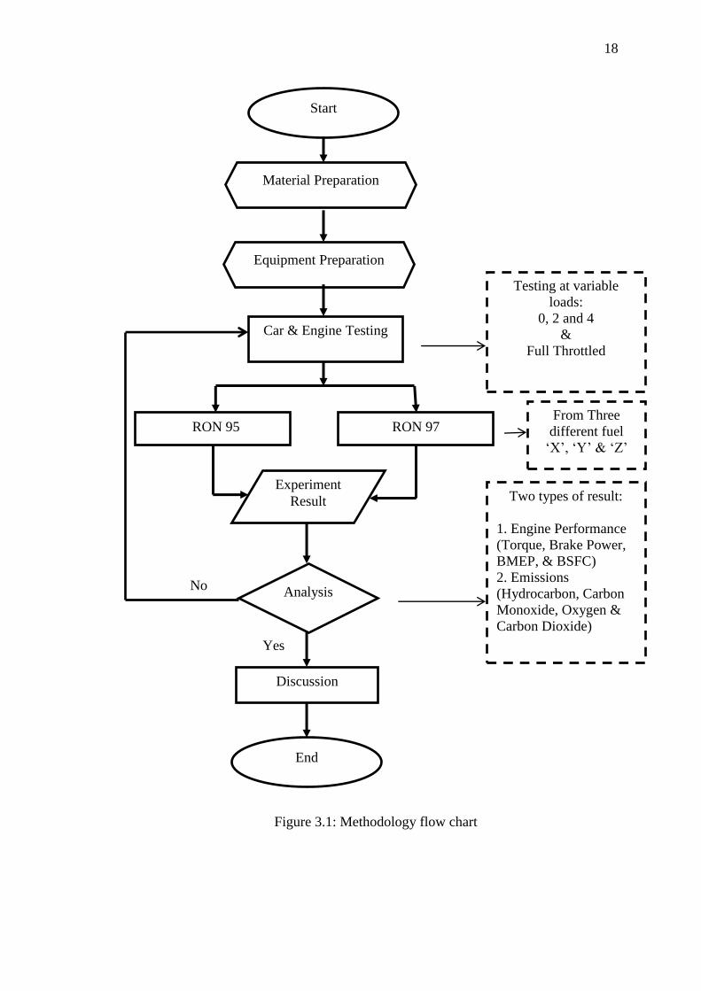
3.2 Methodology Flow Chart
The flow chart shown on Figure 3.1 is for the engine testing to determine the
performance and emission. This will be the guideline for sequence from staring of
material preparation until the result and analysis
18
Figure 3.1: Methodology flow chart
Start
Material Preparation
Equipment Preparation
Car & Engine Testing
RON 95 RON 97
Experiment
Result
End
Testing at variable
loads:
0, 2 and 4
&
Full Throttled
Two types of result:
1. Engine Performance
(Torque, Brake Power,
BMEP, & BSFC)
2. Emissions
(Hydrocarbon, Carbon
Monoxide, Oxygen &
Carbon Dioxide)
From Three
different fuel
„X‟, „Y‟ & „Z‟
Analysis
Yes
No
Discussion
19
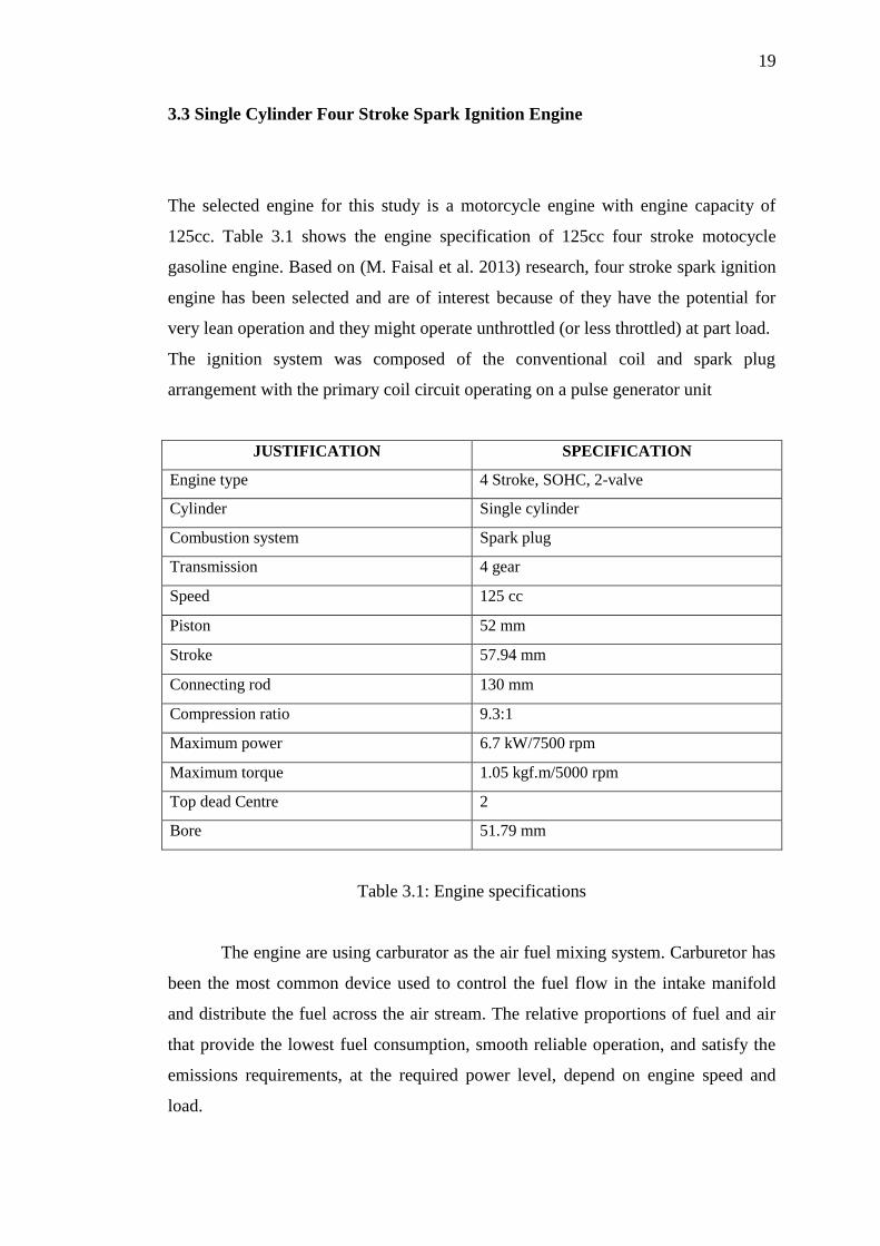
3.3 Single Cylinder Four Stroke Spark Ignition Engine
The selected engine for this study is a motorcycle engine with engine capacity of
125cc. Table 3.1 shows the engine specification of 125cc four stroke motocycle
gasoline engine. Based on (M. Faisal et al. 2013) research, four stroke spark ignition
engine has been selected and are of interest because of they have the potential for
very lean operation and they might operate unthrottled (or less throttled) at part load.
The ignition system was composed of the conventional coil and spark plug
arrangement with the primary coil circuit operating on a pulse generator unit
JUSTIFICATION SPECIFICATION
Engine type 4 Stroke, SOHC, 2-valve
Cylinder Single cylinder
Combustion system Spark plug
Transmission 4 gear
Speed 125 cc
Piston 52 mm
Stroke 57.94 mm
Connecting rod 130 mm
Compression ratio 9.3:1
Maximum power 6.7 kW/7500 rpm
Maximum torque 1.05 kgf.m/5000 rpm
Top dead Centre 2
Bore 51.79 mm
Table 3.1: Engine specifications
The engine are using carburator as the air fuel mixing system. Carburetor has
been the most common device used to control the fuel flow in the intake manifold
and distribute the fuel across the air stream. The relative proportions of fuel and air
that provide the lowest fuel consumption, smooth reliable operation, and satisfy the
emissions requirements, at the required power level, depend on engine speed and
load.

20
3.4 Engine Dynamometer Test Bench
The dynamometer used to measures the power output of single cylinder internal
combustion engines up to their power capacity. It consists of three main elements
which is the controller with load unit, an air cooled synchronous motor and a single
cylinder four stroke gasoline engine air cooled with carburettor system as shown in
Figure 3.2. The main function of the synchronous motor is to provide the required
braking power. The torque and speed are generated by way of a frequency converter.
The regenerative feedback of the braking energy into the system provides highly
energy-efficient operation. The torque is measured by means of a suspended brake
unit and force sensor. The engine is mounted on a vibration-insulated base plate and
connected to the synchronous motor. The mass of the base plate in conjunction with
the soft bearing support ensures that the test stand runs very smoothly, so there is no
need for a solid foundation. The synchronous motor is initially used to start the
engine. As soon as the engine is running, the synchronous motor and regenerative
feedback unit act as a brake unit for applying a load to the engine. The braking power
is fed back into the electrical system. The air consumption is measured by way of a
measuring nozzle. The switch cabinet contains digital displays for the speed, torque
and temperatures as shown in Figure 3.3. Pressure gauges indicate negative intake
pressure and air consumption.

21
Figure 3.2: Dynamometer test bench (GUNT Hamburg, 2005)
Figure 3.3: Digital display unit on the test bench (GUNT Hamburg, 2005)

22
It is consider a simplified engine test procedure to analyse the performance
of different RON fuel grades and brands. Using the dynamometer eliminate the
complication of high end instrumentation and control as presented in a typical engine
dynamometer test equipment.
The fix parameter is the engine speed and the variable parameter is the load
attached to the engine. The engine speed controlled by turn the accelerator pedal to
the maximum level and attached the load required. The data output display on
computer or manual calculation will show the performance of the engine. A sample
of computer output display from a trial run showing the performance as in the Figure
3.4.
Figure 3.4: Output Display on Software (GUNT Hamburg, 2005)
3.4 Gas Analyzer
Gas analyzer is used to measure the amount of gas emission level produced by
vehicle with different type of RON grades and fuel brands as shown in Figure 3.5.
An AUTOCheck exhaust emissions analyzers is used in order to get the accurate data

23
of exhaust gas emissions. Combustion analysis is a part of a process intended to
improve fuel economy, reduce undesirable exhaust emissions and improve the safety
of fuel burning equipment. Combustion analysis begins with the measurement of flue
gas concentration and gas temperature, and many include the measurement of draft
pressure and soot level. (TSI Incorporated, 2004). The portable automobile exhaust
emission analyzer is a device that can measure the gas emissions of both gasoline
and diesel fuelled vehicle instantaneously or over a limited period of time. For
gasoline fuelled vehicle, the device detects and displays the amount of the following
air pollutants, namely, hydrocarbons (HC), carbon monoxide (CO), and nitrous
oxides (NOx). The gas analyzer consists of sensor, input devices, a microcontroller
and a LCD displays. The data obtained will be tabulated to show the different
between both fuels on different fuel producer.
Figure 3.5: AUTOCheck gas analyzer

24
3.5 Fuel Consumption Meter
Fuel consumption is the biggest issue in the study because it related to the cost
impact to the consumer. The fuel consumption data on every different fuel will be
recorded and calculate depend on the current fuel price. An Ono Sokki FZ-2100 fuel
consumption meter as in Figure 3.6 will be used in this study in order to get the
accurate result. The fuel consumption reading will be recorded parallel with the
dynamometer testing. These flow meters use the principle of the coriolis force which
is generated when the movement of a mass and rotation occur simultaneously. It
capable for high accuracy, continuous measurement of mass flow and are ideal for
applications such as measuring the amount of fuel consumption behaviour in mode
test and fuel consumption behaviour when the speed is accelerated or decelerated.
Figure 3.6: Ono Sokki fuel consumption meter
The reading of this meter is in mass flow (kg/hr) rate or volume flow rate
(L/hr). The fuel consumption will vary at different engine revolution. This variation
will be recorded for each RON for every fuel producer. The data will be tabulated
and plot on the graph for the clear picture of the engine consumption.

56
REFERENCES
W.W. Pulkrabek, (2004) Engineering Fundamentals of the Internal Combustion
Engine. United States. Pearson Prentice Hall
J.D. Halderman, (2007) Automotive Engine Performance. United States. Pearson
Prentice Hall
John B.Heywood (1988) Internal Combustion Engine Fundamentals United States
McGraw Hill Siries in Mechanical Engineering
Ashhab, “Moh‟d Sami”, Mahmoud Abu-Zaid, Odai Baqaeen, Maraam Khdair, and
Eyas Adel. "Experimental Study of Emissions and Performance of Internal
Combustion Engine Fuels." International Journal of Thermal and Environmental
Engineering 3, no. 2 (2010): 95-100.
Binjuwair, Saud, Taib Iskandar Mohamad, Ahmed Almaleki, Abdullah Alkudsi, and
Ibrahim Alshunaifi. "The Effects of Research Octane Number and Fuel Systems
on the Performance and Emissions of a Spark Ignition Engine: A Study on
Saudi Arabian Ron91 and Ron95 with Port Injection and Direct Injection
Systems." Fuel 158, no. 0 (10/15/ 2015): 351-60.
erri, Tarcisio, Gianluca ‟Errico, and Angelo Onorati. "Experimental
Investigations on High Octane Number Gasoline Formulations for Internal
Combustion Engines." Fuel 111, no. 0 (9// 2013): 305-15.
Chun-hua, Zhang, P. A. N. Jiang-ru, Tong Juan-juan, and L. I. Jing. "Effects of Intake
Temperature and Excessive Air Coefficient on Combustion Characteristics and
Emissions of Hcci Combustion." Procedia Environmental Sciences 11, Part C,
no. 0 (// 2011): 1119-27.
Cinar, Can, Ahmet Uyumaz, Hamit Solmaz, Fatih Sahin, Seyfi Polat, and Emre
Yilmaz. "Effects of Intake Air Temperature on Combustion, Performance and
Emission Characteristics of a Hcci Engine Fueled with the Blends of 20% N-
Heptane and 80% Isooctane Fuels." Fuel Processing Technology 130, no. 0 (2//
2015): 275-81.

57
Gong, Chang-Ming, Kuo Huang, Jing-Long Jia, Yan Su, Qing Gao, and Xun-Jun
Liu. "Improvement of Fuel Economy of a Direct-Injection Spark-Ignition
Methanol Engine under Light Loads." Fuel 90, no. 5 (2011): 1826-32.
H. W. Gitano-Briggs (2010) Analysis of Motorcycle Fuel Consumption in Malaysia,
SAE2010-10SETC-0064
Kumar, K. Senthil, and R. Thundil Karuppa Raj. "Effect of Fuel Injection Timing and
Elevated Intake Air Temperature on the Combustion and Emission
Characteristics of Dual Fuel Operated Diesel Engine." Procedia Engineering
64, no. 0 (// 2013): 1191-98.
Leermakers, C. A. J., P. C. Bakker, B. C. W. Nijssen, L. M. T. Somers, and B. H.
Johansson. "Low Octane Fuel Composition Effects on the Load Range
Capability of Partially Premixed Combustion." Fuel 135 (2014): 210-22.
M. Ashhab, M. Abu Zaid, O. Baqaeen, M. Khdair, E. Adel, (2011) "Experimental
Study of emissions and Performance of Internal Combustion Engine, Fuels"
Volume 3, No.2 (2011) 95-100, Mutah University, Jordan.
Maurya, Rakesh Kumar, and Avinash Kumar Agarwal. "Experimental Investigation
on the Effect of Intake Air Temperature and Air–Fuel Ratio on Cycle-to-Cycle
Variations of Hcci Combustion and Performance Parameters." Applied Energy
88, no. 4 (4// 2011): 1153-63.
Mohamad, Taib Iskandar, and Heoy Geok How. "Part-Load Performance and
Emissions of a Spark Ignition Engine Fueled with Ron95 and Ron97 Gasoline:
Technical Viewpoint on Malaysia’s Fuel Price Debate." Energy Conversion and
Management 88 (2014): 928-35.
R. Mamat, N. R., Abdullah, N., Tamaldin, (2010) "Emissions of a Single Cylinder
Diesel Engine Operating with Ethanol, Engineering Mechanics & Transport"
(EMT-2010), 25-27 Nov 2010, LVIV,Ukraine
Sayin, Cenk. "The Impact of Varying Spark Timing at Different Octane Numbers on
the Performance and Emission Characteristics in a Gasoline Engine." Fuel 97,
no. 0 (7// 2012): 856-61.
Sayin, Cenk, Ibrahim Kilicaslan, Mustafa Canakci, and Necati Ozsezen. "An
Experimental Study of the Effect of Octane Number Higher Than Engine
Requirement on the Engine Performance and Emissions." Applied Thermal
Engineering 25, no. 8–9 (6// 2005): 1315-24.

58
Yang, Hongqiang, Shijin Shuai, Zhi Wang, and Jianxin Wang. "Fuel Octane Effects
on Gasoline Multiple Premixed Compression Ignition (Mpci) Mode." Fuel 103
(2013): 373-79.