ii radio questions
TRANSCRIPT
7,qemw-.‘nw-ary--ott.e, ,ono-cRAFT LIBRAR
tAP
• •
NEW RADIO
QUESTIONS AND
ANSWERS ANSWERS TO QUESTIONS
MOST FREQUENTLY ASKED
BY BOTH NOVICES AND EXPERTS
BY ROBERT EICHBERG
pui131-11SHIIED
feeCRAFT PUBLICATIONT. ebi 99 Huosort ST -NEW YoRK
II
—
s.
• — Is, .ramer.
•
o
E
7 1,800 PAGES
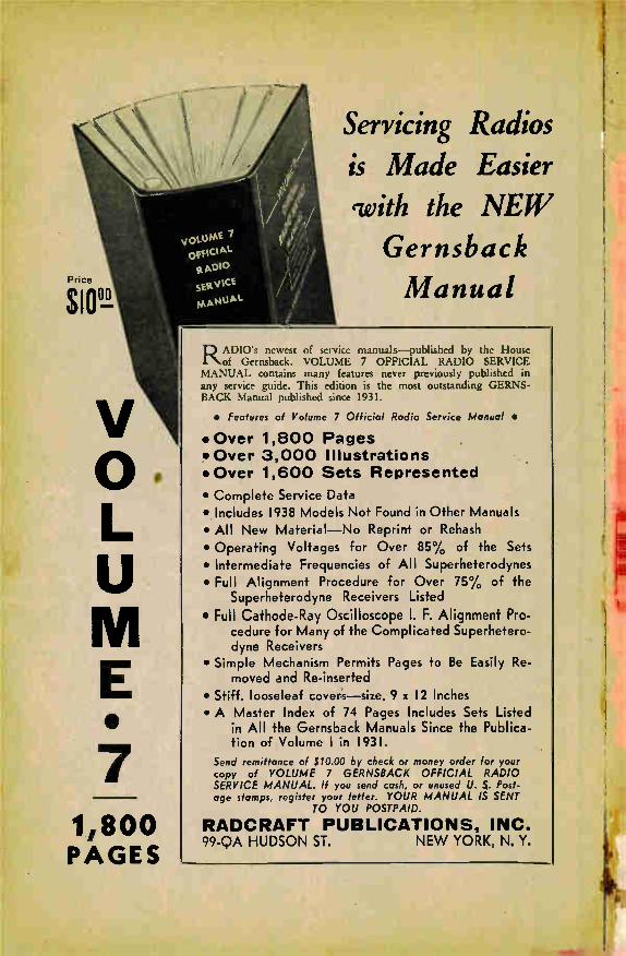
Servicing Radios is Made Easier with the NEW
Gernsback Manual
RADIO's newest of service manuals—published by the House of Gernsback. VOLUME 7 OFFICIAL RADIO SERVICE
MANUAL contains many features never previously published in any service guide. This edition is the most outstanding GERNS-BACK Manual published since 1931.
• Features of Volume 7 Official Radio Service Manual •
• Over 1,800 Pages • Over 3,000 Illustrations •Over 1,600 Sets Represented
• Complete Service Data • Includes 1938 Models Not Found in Other Manuals • All New Material—No Reprint or Rehash
• Operating Voltages for Over 85% of the Sets
• Intermediate Frequencies of All Superheterodynes • Full Alignment Procedure for Over 75% of the
Superheterodyne Receivers Listed • Full Cathode-Ray Oscilloscope I. F. Alignment Pro-
cedure for Many of the Complicated Superhetero-dyne Receivers
• Simple Mechanism Permits Pages to Be Easily Re-moved and Re-inserted
• Stiff, looseleaf covers—size, 9 x 12 Inches • A Master Index of 74 Pages Includes Sets Listed
in All the Gernsback Manuals Since the Publica-tion of Volume 1 in 1931.
Send remittance of $10.00 by check or money order for your copy of VOLUME 7 GERNSBACK OFFICIAL RADIO SERVICE MANUAL. If you send cash, or unused U. $. Post-age stamps, register your letter. YOUR MANUAL IS SENT
TO YOU POSTPAID.
RADCRAFT PUBLICATIONS, INC. 99-QA HUDSON ST. NEW YORK, N. Y.

New Radio Questions And Answers
ANSWERS TO ,QUESTIONS
MOST FREQUENTLY ASKED
BY BOTH NOVICES AND EXPERTS
•
BY
ROBERT EICHBERG
RADCRAFT PUBLICATIONS, INC.
PUBLISHERS
99 HUDSON STREET NEW YORK, N. Y.
Copyright 1938 by Hugo Gernsback Printed in U. S. A.

Contents
Chapter 1—Definitions
Chapter 2—Vacuum Tubes
Chapter 3—The Antenna System 12
Chapter 4—Radio Frequency Circuits 1
Chapter 5—Audio Frequency Circuits 1( ,
Chapter 6—Reproducers is
Chapter 7—Power Supplies 20
Chapter 8—Superheterodyne Receivers 22
Chapter 9—Television and Facsimile 2ç
Chapter 10—Short Waves 27
Chapter 11—Automotive Radio 30
Chapter 12—Sound Equipment 32
Chapter 13—Home Recording 34
Chapter 14—Test Apparatus
Chapter 15—General Inquiries 41
Chapter 16—Causes of Set Failure 43
Chapter 17—Service Problems 44
Chapter 18—Choosing and Installing a Receiver 46
Chapter 19—How a Set Works 47
Chapter 20—Handy Reference Data 50
Chapter 21—Running a Radio Service Business 57
Chapter 22—Conclusion 61
Ever since the first radio enthusiast put the crystal detector in series with a pair of phones and listened to
old K DK A sending out its test programs, questions have arisen relative to circuits, components and theories.
In eighteen years of radio experience the writer has answered many hundreds of thousands of questions from
radio listeners. From these, those of most general in-terest have been selected, tabulated and classified under general headings for easy reference.
Radio developments bring such rapid changes that it is virtually impossible for anyone not actively engaged in
the radio industry to keep abreast without reference to some work of this nature. Therefore, questions relating
to automatic tuning, automatic volume control, phono-radio, auto-radio and various other phases of the art have been selected for inclusion in this volume.

Set Ailments and Their Symptoms In order to save space, numerous questions as to "Can defective A.F. transformers be the cause of insufficient volume?" or "Do you think my loud speaker is going bad? My set sounds tinny." etc., the following table, adapted from material which has appeared in Radio-Crait and Radio Today. It lists the elements of the receiver, and the symptoms
which defects in them may cause.
Alignment of Stages Lack of Sensitivity Spotty Sensitivity Poor Tone Quality Circuit Oscillation Code Interference Off-Calibration of Dial Poor Selectivity Spotty Selectivity
Antenna, Ground & Lightning Arrester No Short-Wave Reception Intermittent Reception Poor Reception Lack of Volume Excessive Noise Fading
A.F. Transformers Noisy Reception No Reception Reduced Volume Intermittent Reception Poor Tone Quality
Coils, R.F. and I.F. Intermittent Reception Off-Calibration of Dial Poor Selectivity Spotty Selectivity Lack of Sensitivity Spotty Sensitivity Poor Fidelity No Reception Fading Cross-Talk Circuit Oscillation
Condensers, Bypass Circuit Oscillation Poor Tone Quality Cross-Talk Intermittent Reception Poor A.V.C. Action Fading Loss of Volume H urn Excessive Hiss Noisy Reception Off-Calibration of Dial No Reception Short-Wave Dead Spot
Condensers, Filter Excessive Hum No Reception Low Volume Intermittent Reception Circuit Oscillation
Condensers, Tuning Noisy Reception Dead Spots Intermittent Reception Microphonic Howls Off-Calibration of Dial Fading
Interference, I.F. Wavetrap Code Interference Intermittent Reception
Interference, Atmospheric Conditions
Fading Noisy Reception Distortion Lack of Short-Wave
Reception Cross-Talk
Interference, House Wiring
Intermittent Reception No Reception Noisy Reception
Interference, Local Machinery and Appliances
Noisy Reception Clicks Sudden Change in Volume
Interference, Pipes in House
Intermittent Reception Noisy Reception
Line Cord and Plug Intermittent Reception No Reception Noisy Reception
Oscillator Section Lack of Sensitivity Excessive Hiss Distortion Erratic Operation Dead Spots on Short Waves
Frequency Instability Intermittent Operation Whistling
Power Transformer No Reception Intermittent Reception Excessive Noise Excessive Hum Short Tube Life
Radio Cabinet Resonance Tinny Sounds Rumbles
Reproducer Distortion Tinny Sounds Scratching and Grating Excessive Hum
Intermittent Reception No Reception Low Volume
Resistors Intermittent Reception Distortion Poor A.VC. Action Fading Circuit Oscillation No Reception Low Volume Short Tube Life
Shielding of Set and Components
Circuit Oscillation Microphonics Noisy Reception Lack of Sensitivity Cross-Talk Fading Intermittent Reception
Tubes No Reception Distortion Hum Off-Calibration of Dial Lack of Sensitivity Loss of Selectivity Microphonics Intermittent Reception Fading adin
eA.V.C. Action Noisy Reception Circuit Oscillation
Volume and Tone Controls
Noisy Reception No Control of Volume Sudden Change in Volume
No Control of Tone Sudden Change in Tone Intermittent Reception No Reception Loss of Sensitivity Circuit Oscillation
Wave-Change Switch Loss of Volume on
Short Waves Intermittent Operation No Reception Noisy Reception Short-Wave Dead Spots Fading Loss of Volume A.V.C. Not Functioning
Wiring of Set Noisy Reception Excessive Hum Circuit Oscillation Lack of Short-Wave
Reception No Reception Cross-Talk
NEW RADIO QUESTIONS AND ANSWERS
CHAPTER I
Definitions
A.C. AND D.C. (Q) What is the difference between Alternating
Current (A.C.) and Direct Current (D.C.)? (A) Alternating current reverses its direction
of flow at regularly recurring intervals. In stand-ard house lighting current, the cycle is: Zero, maximum positive, Zero, maximum negative, Zero, and takes place completely 60 times per second. In brief, both terminals of the line go through this cycle, one being maximum positive when the other is maximum negative.
Direct current flows in one direction only, like the current from a battery.
A.C., for radio purposes, is more flexible; its voltage may be raised or lowered through the use of a transformer, and it is easily rectified (changed to direct current) when D.C. is needed. D.C.
AC
0 C
o
o
Fig. 1
may have its voltage reduced by being passed through a resistor; its voltage raised by changing it into a pulsating D.C. (which acts like A.C. by mechanical means, such as a vibrator, or by certain tubes. It may then be handled like A.C., but must be rectified again to be used as D.C. at the new voltage.
AUDIO-FREQUENCY AMPLIFIER (Q) What is an audio frequency amplifier? (A) Frequency is the number of vibrations (or
electrical impulses) per second. If the air is caused to vibrate at any frequency from about 30 to 14,000 times per second, the vibrations are audible—they can be heard by the human ear. An Audio-Frequency Amplifier is a device con-structed to strengthen electrical impulses of the frequencies lying between these limits.
- - AUTODYNE CIRCUITS
(Q) I have been told that my set is an auto• dyne receiver, but I bought it for a superhetero-dyne. Was I misled?
(A) No. An autodyne is a superhet which uses the saine tube as oscillator and first detector.
AUTOMATIC VOLUME CONTROL (Q) What is an automatic volume control?
Does it replace the usual manual volume control? (A) The automatic volume control is a highly
ingenious circuit which keeps the output of an intermediate frequency amplifier approximately constant, though the signal input to the amplifier may vary widely. It does not replace the manual volume control.
Quiet automatic volume control (p.A.v.c.) is a means of reducing the set's sensitivity at will; so that background noise between stations will riot be heard while the set is being tuned, though the signal input of a station's carrier wave will cause the set to function.
5
BAFFLES (Q) What are baffles, and what are the "magic
voice," the "labyrinth" and similar set features? (A) When a loud speaker is reproducing the
program of a station, its diaphragm vibrates, caus-ing the air which rests against the back of the diaphragm to vibrate, as well as that which rests against the front of the diaphragm. There is some tendency of these vibrations to "cancel out," es-pecially in the lower registers, but by placing the speaker in the center of a partition, the path which air vibrations must travel to get from the front of the speaker around to the back is greatly lengthened, and bass reproduction is improved. The longer the path, within certain limits, the bet-ter the reproduction, and the "labyrinth" forms a long. non•resonating path. The "magic voice" is another baffle system, tuned to resonate at fre-quencies which usually come through the ampli-fier weakly; thus it builds them up. Of course, if the back of the loud speaker were
sealed in, there would he no path from front to back, but this cannot be done. One reason is that the air cushion formed in the rear chamber would muffle the speaker tones.
BY-PASS CONDENSER (Q) How can you tell a by-pass condenser from
other condensers by looking at it? (A) By-pass does not describe the condenser
itself, but its use. It is simply a condenser used to provide a low impedance path for an alternating (or pulsating direct) current around some unit which has a higher A.C. impedance. For ex-ample, it is used to by-pass radio-frequency cur-rents through a circuit, so that they will not have to travel through a power pack. You cannot tell by looking at a condenser; you can tell by analysing its purpose in a circuit.
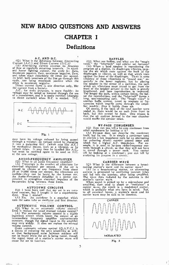
CARRIER WAVE (Q) What is the difference between a broad-
casting station's wave and its carrier wave? (A) In a broadcasting station, an alternating
current is generated by oscillating vacuum tubes and fed into the antenna, after being amplified. The wave then radiated by the antenna is the station's carrier wave. When sound is picked up by a microphone and
amplified, then used to shape or "modulate" a carrier wave, the result is a modulated carrier, which is probably what you have in mind. But, to all practical intent, a station's wave and its carrier wave may be said to be identical.
CARRIER
MODULATED
Fig. 2
6 NEW RADIO QUESTIONS & ANSWERS
BAND-PASS FILTER (Q) My set is said to have a band-pass filter.
What is that? (A) A filter, electrically, is a circuit which
prevents the passage of certain frequencies. A band-pass filter prevents the passage of all fre-quencies not in a certain continuous group, or "band."
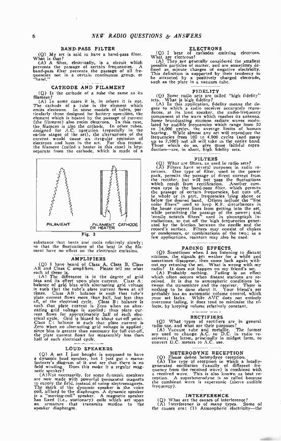
- - - CATHODE AND FILAMENT
(Q) Is the cathode of a tube the same as its filament?
(A) In some cases it is, in others it is not. The cathode of a tube is the element which emits electrons. In some models of tubes, par-ticularly those designed for battery operation, the element which is heated by the passage of current (the filament) also emits electrons. In this case, the filament is also the cathode. In other tubes, designed for A.C. operation (especially in the earlier stages of the set), the alternations of the current would cause an irregular emission of electrons and hum in the set. For this reason, the filament (called a heater in this case) is kept separate from the cathode, which is made of a
FILAMENT FILAMENT CATHODE OR HEATER
Fig. 3
substance that heats and cools relatively slowly; so that the fluctuations of the heat in the fila-ment have no effect on the electronic emission.
AMPLIFIERS (Q) I have heard of Class A, Class B, Class
AB and Class C amplifiers. Please tell me what each of these is.
(A) The difference is in the degree of grid bias and its effect upon plate current. Class A: balance of grid bias with alternating grid voltage is such that the tube's plate current flows at all times. Class AB: balance is such that tube's plate current flows more than half, but less than all, of the electrical cycle. Class B: balance is such that plate current is Zero when no alter-nating grid voltage is applied; thus plate cur-rent flows for approximately half of each elec-trical cycle. Grid is biased to about cut-off point. Class C: balance is such that plate current is Zero when no alternating grid voltage is applied ; since bias is greater than necessary for full cut-off, the plate current flows for measurably less than half of each electrical cycle.
LOUD SPEAKERS (Q) A set I just bought is supposed to have
a dynamic loud speaker, but I just got a manu-facturer's diagram of it and see that there is no field winding. Does this make it a regular mag-netic speaker?
(A)Not necessarily, for some dynamic speakers are now made with powerful permanent magnets to supply the field, instead of using electromagnets. The mark of the dynamic speaker is the voice coil, affixed to the diaphragm. A dynamic speaker is a "moving-coil" speaker. A magnetic speaker has fixed (i.e., stationary) coils which act upon an armature that transmits motion to the speaker diaphragm.
ELECTRONS (Q) I hear of cathodes emitting electrons.
What are electrons? (A) They are generally considered the smallest
possible particles of matter, and are sometimes de-fined as minute charges of negative electricity. This definition is supported by their tendency to be attracted by a positively charged electrode, such as the plate in a vacuum tube.
FIDELITY • (Q) Some radio sets are called "high fidelity" sets. What is high fidelity?
(A) In this application, fidelity means the de-gree to which a radio receiver accurately repro-duces, at its loud speaker, the audio-frequency component of the wave which reaches its antenna. Some broadcasting stations radiate waves modu-lated by audible frequencies which range from 30 to 14,000 cycles, the average limits of human hearing. While almost any set will reproduce the frequencies from 100 to 4.000 cycles (and many up to 7,500) not all will take in the entire band. Those which do so, give more faithful repro-duction—are, in short, high fidelity sets.
- FILTERS
(Q) What are filters, as used in radio sets? (A) Filters have several purposes in radio re-
ceivers. One type of filter, used in the power pack, permits the passage of direct current from the rectifier, but will not pass the fluctuations which result from rectification. Another com-mon type is the band-pass filter, which permits the passage of certain frequencies, but cuts off, in whole or in part, frequencies lying above or below the desired band. Others include the "line noise filters" used to keep R.F. disturbances in the house current lines from getting into the set, while permitting the passage of the power; and 'needle scratch filters" used in phonograph in-stallations, to cut off the high frequencies gener-ated by the friction between the needle and the record's surface. Filters may consist of chokes or condensers, or combinations of the two; in a few applications, resistors may also be used.
FADING EFFECTS (9) Sometimes when I am listening to distant
stations, the signals get weaker for a while and sometimes disappear, then come back again with-out my retuning the set. What is wrong with my radio? It does not happen on my friend's set.
(A) Probably nothing. Fading is an effect which often occurs when distant stations are re-ceived. It is due to atmospheric conditions be-tween the transmitter and the receiver. There is nothing to be done about it. Your friend's set probably has an automatic volume control, which your set lacks. While AVC does not entirely overcome fading, it does tend to minimise the ef-fects, by keeping volume relatively constant.
RECTIFIERS (Q) What types of rectifiers are in general
radio use, and what are their purposes? (A) Vacuum tube and metallic. The former
are used to change A.C. to D.C. in radio re-ceivers; the latter, principally in midget form, to convert D.C. meters to A.C. use.
HETERODYNE RECEPTION (Q) Please define heterodyne reception. (A) The type of reception in which a locally-
generated oscillation (usually of different fre-quency from the received wave) is combined with a received wave. This is also known as beat re-ception. A superheterodyne is so called because the combined wave is supersonic (above audible frequency).
INTERFERENCE (Q) What are the causes of interference? (A) Interference is of many types. Some of
the causes are: (1) Atmospheric electricity—the

NEW RADIO QUESTIONS & ANSWERS 7
true "static"; (2) Electric disturbances caused by motors, switches, arcing, etc.—called "man-made static"; (3) Signals of undesired stations; (4) Heterodyning between the waves of a received sta-tion and an undesired station; (5) Line noise, entering the set through the power pack; etc.
KILOCYCLES (Q) 1 see stations rated according to kilo--
cycles. Does this mean their power? (A) No. A station's wave is A.C., and kilo-
cycles refers to the frequency, or number of tunes this current alternates from Zero to maxi-mum positive to Zero to maximum negative to Zero each second. Each complete alternation de-scribed is one cycle; 1000 cycles per second is one kilocycle. Frequency (of cycles per second) has nothing to do with power; power is rated in watts or kilowatts (a kilowatt is 1000 watts).
— - MEANING OF MEG.
(Q) I know what ohms :ind cycles are, but what are megohms and megacycles? Are they larger or smaller than ohms and cycles?
(A) Larger. The prefix "meg" or "mega" means 1,000,000. Thus 1 megohm is 1,000,000 ohms, etc. Other prefixes and their common abbreviations will be found at the beginning of this chapter.
MERCURY VAPOR RECTIFIERS (Q) What is the difference between a mercury
vapor rectifier and other rectifiers? (A) The mercury vapor rectifier, as the name
implies, contains a little mercury which becomes vaporised when the tube is in operation. This decreases the internal resistance of the tube, so that there is less voltage drzp in it.
MICROPHONES (Q) What is a microphone, and how does it
work? (A) A microphone is simply a device for con-
verting sound waves to pulsating D.C. or A.C., of corresponding frequency and proportional am-
DYNAMIC MIC.
CARBON Mmc
1111 CRYSTAL MIC
El
CONDENSER AMC.
1-, RIBBON MIC.,
r i
Fig. 4
plitude. There are five principle types in general use; dynamic. crystal, ribbon, condenser and car-bon. The latter is merely a variable resistance, varied by movement of a diaphragm, actuated by sound waves, and controlling contact between the carbon grains in a small container. The dynamic is a diaphragm moving a coil in a magnetic field, and thus generating currents; the crystal is a dia-phragm applying torque (twist) to a piezo-elec-tric crystal, and thus generating currents; the ribbon is a metal strip cutting a magnetic field, and thus generating currents. The condenser makes use of the diaphragm as one of its plates, and thus varies the grid charge of a pre-amplifier.
MODULATION (Q) When they say that a radio wave is
modulated, what do they mean?
(A) They mean that the wave is "shaped" in accordance with an audio signal. This is done by decreasing the amplitude, phase or frequency of some of the waves in the carrier.
PULSATING D. C. (Q) Is there any difference between A.C. and
pulsating D.C.? (A) Yes. A definition of A.C. is given at the
beginning of this chapter. Pulsating D.C. is cur-rent which flows in but one direction; it may be interrupted, coming to a full stop at intervals, or may simply be flowing with greater and lesser force. It is as though an equal or lesser A.C. were flowing in the same circuit as the D.C.
- - - PUSH-PULL
(Q) What does push-pull mean? (A) It is generally used to refer to a stage of
audio amplification, in which two tubes operate 180 degrees out of phase, the grid of one being maximum negative when that of the other is
Fig. S
maximum positive. It may also refer to a micro-phone in which the two elements are similarly out of phase, as the double-button carbon micro-phone.
SELECTIVITY (Q) What is the selectivity of a radio set? (A) It is the ability of the set's circuits to
tune to a desired carrier wave, while rejecting all others.
SENSITIVITY (Q) And what is a set's sensitivity? (A) The set's ability to respond to the sig-
nal to which it is tuned. A sensitive set will pick up and reproduce signals which a less sensi-tive set will miss.
SIDE BANDS (Q) I know what a carrier wave is, but what
are the side bands? And what is single-side-band transmission ?
(A) The side bands are the frequencies on either side of the carrier wave's frequency and result from modulation. If a set is too selec-tive, part of these side bands may be cut off. with resulting loss of fidelity. In single side band transmission, one of the side bands (and sometimes the carrier) is suppressed.
SUPERHETERODYNES (Q) How is a superheterodyne different from
other radio sets? (A) In most other circuits, the signal is am-
plified at radio frequencies, detected, and ampli-fied at audio frequencies. In superheterodynes, it may be amplified at radio frequencies, but must be "mixed" with a locally generated fre-
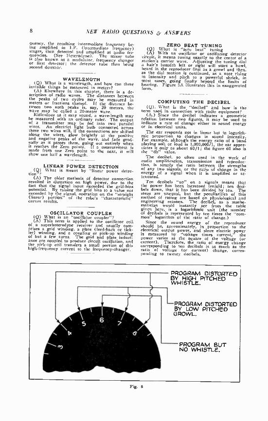
Fig. 6
8 NEW RADIO QUESTIONS 6, ANSWERS
quency, the resulting intermediate frequency be-ing amplified in I.F. (intermediate frequency) stages, then detected and amplified at audio fre-quencies. (See Heterodyne). The mixer tube is also known as a modulator, frequency changer or first detector; the detector tube then being second detector.
WAVELENGTH (Q) What is a wavelength, and how can these
invisible things be measured in meters? (A) Elsewhere in this chapter, there is a de-
scription of radio waves. The distances between the peaks of two cycles may be measured in meters or fractions thereof. If the distance be-tween two such peaks is, say, 20 meters, the wave may be called a 20-meter wave.
Ridiculous as it may sound, a wave-length may be measured with an ordinary ruler. The output of a transmitter may be fed into two parallel wires. An electrict light bulb connected across these two wires will, if the connections are shifted along the wires, glow brightly at the positive and negative peaks of the wave, and fade grad-ually as it passes them, going out entirely when it reaches the Zero points. If a measurement is made from one Zero point to the next, it will show one half a wavelength.
LINEAR POWER DETECTION (Q) What is meant by "linear power detec-
tion"? (A) The older methods of detector connection
resulted in distortion on high power, due to the fact that the signal input exceeded the grid-bias potential. By raising the grid bias to a value not exceeded by the signal, operation on the "straight (linear) portion" of the tube's "characteristic" curves results.
OSCILLATOR COUPLER (Q) What is an "oscillator coupler"? (A) This term is applied to the oscillator coil
of a superheterodyne receiver and usually com-prises a grid winding, a plate (feed-back or tick-ler) winding, and a coupling or pick:up winding of but a few turns. The grid and plate induct: ance are coupled to produce circuit oscillation, and the pick-up coil transfers a small portion of this high-frequency current to the frequency-changer.
ZERO BEAT TUNING (Q) What is "zero beat" tuning (A) With an oscillator or oscillating detector
circuit, it means tuning exactly to the center of a station's carrier wave. Adjusting the tuning dial a hair's breadth left or right will start a howl, heard in the reproducer first as a growl and then, as the dial motion is continued, as a note rising in intensity and pitch to a powerful shriek, in most cases, going finally beyond the limits of hearing. Figure 5A illustrates this in exaggerated form.
COMPUTING THE DECIBEL (Q). What is the "decibel" and how is the
term used in connection with radio equipment? (A.) Since the decibel indicates a geometric
relation between two figures, it may be used to indicate a rate of change either in sound energy or in electrical units. The ear responds not in linear but in logarith-
mic proportion to changes in sound intensity. For example, although the energy ratio of a band playing soft or loud is 1,000,000/1, the ear appre-ciates it only as about 60/1; the figure 60 also is the "db" value. The decibel. so often used in the work of
audio amplification, transmission and reproduc-tion, is simply the ratio between the strengths of any two signals, or the ratio of change in the energy of a signal when it is amplified or at-tenuated. Ten decibels "up" on a signals means that
the power has been increased tenfold; ten deci-bels down, that it has been divided by ten. The steps are unequal, but the peculiarities of this method of rating are based on physiological and engineering reasons. The decibel, as a mathe-matician would instantly see from the table given here, is a logarithmic unit (the number of decibels is represented by ten times the "com-mon" logarithm of the ratio of change.)
Since the sound energy of the reproducer should be, approximately, in proportion to the electrical output power, and since electric power is measured by "voltage times current," the power varies as the square of the voltage (or current). Therefore, the ratio of energy change corresponding to ten decibels is as much as the ratio of voltage (or current) change, corres-ponding to twenty decibels.
PROGRAM DISTORTED BY HIGH PITCHED WHISTLE.
PROGRAM DISTORTED BY LOW PITCHED GROWL.
PROGRAM BUT NO WHISTLE.

NEW R.41)10 QUESTIONS s- ANSWERS 9
Any signal strength may be taken as the base í or zero) in computing relative intensities. How-ever, for voice-transmission measurements, six milli-watts (1.73 volts across a 500-ohm line) is a standard used by engineers.
The ratio of change in power, and in voltage
(or current) corresponding to any number of decibels, may be quickly found from the follow-ing table. Multiply the signal strength (or voltage) which is taken as the base, by the factor given in the proper column, opposite the ap-propriate number of decibels.
^or 'DOWN" DEC18215
"UP" "D0120
DECIBELS
ENERGY VOLTAGE NO. ENENOY VOLTAGE ENERGY VOLTAGE NO. 3.118.1GY VOLTAGE
1.26 1.12 1 0.794 0.691 631.0 25.12 28 .0016 .040
1.69 1.26 2 .631 .794 794.3 28.18 29 .0013 .035
2.00 1.41 3 .501 .706 1,000.0 31.82 30 .0010 .032
2.61 1.59 4 .398 .631 1.259 35.48 31 .0008 .028
3.16 1.79 5 .316 .582 1,585 39.81 32 .0006 .025
3.98 2.00 6 .251 .501 1,996 44.87 33 .0005 .022
6.01 2.24 7 .199 .447 2,512 50.12 34 .0004 .020
6.31 2.51 8 .158 .398 3,162 56.23 35 .00032 .018
7.94 2.82 9 .e26 .355 3,981 63.10 36 0°025 ..016
10.00 3.16 10 .100 .316 5,012 70.80 37 .00020 .014
12.59 3.55 11 .079 .282 6,310 79.43 8 .00016 .013
16.85 3.98 12 .063 .251 7,943 89,13 ' .00013 .011
10.90 4.47 13 .080 .224 10.000 130.00 40 .03010 .010
25.12 5.01 14 .040 .200 12,590 112,1 41 .00908 .0089
31.62 5.82 15 .032 .178 15,850 125.9 42 .00008 .0076
39.81 6.31 16 .025 0.158 19,960 141.3 43 .00005 .0071
50.12 7,08 17 .020 .141 25,120 158.5 41 .00004 .0063
63.10 7.94 18 .016 .126 31.620 177,8 45 .000332 .0356
79,43 8.91 19 .013 .112 39,810 199.8 46 .000025 .0050
50,120 223.9 47 .000023 .0045 130.00 10.00 20 .010 .100
63,100 251.3 43 .000016 .0040 125.90 11,22 21 .0079 .089
79,430 282,0 49 .000013 .0036 158.50 12.59 22 .0063 .079
100,900 316.0 50 .900010 .0032 199,60 14.13 23 .0050 .071
1,000,000 1,000 GO .000001 .001
251.20 15.85 24 .0040 .063 10,000,000 3,162 73 .0000001 .0003
316.20 17.78 25 .0032 .056 100,000,000 10.000 80 .00000031 .00001
398.10 19.96 26 .0025 .050 1,000,000,000 31,820 90 .000000001 .00003
501.20 22.39 27 .0020 .047 10,000,033.030 100,000 100 ,0000000001 .00001
Fig. 7

CHAPTER II
Vacuum Tubes
INACTIVE TUBES (9) My set stopped playing and I called a
service man in. He tested my tubes and said I needed two new ones. He installed them and my set played all right . But what I cannot under-stand is why my old tubes were no good; they lit. Will you explain this?
(A) The filament or cathode of a tube is coated or impregnated with a substance which emits electrons when heated by the passage of filament or heater current. These electrons, being negative. are attracted by the positively charged plate. Their flow—the plate current—is controlled by the signal reaching the grid (among other fac-tors). When the substance is used up to some
Fig. 8
degree, the flow of electrons is greatly decreased, so the electronic stream which the grid controls is greatly cut down, and the signal has little ef-fect. The tube must then be discarded.
INTERNAL RESISTANCE (Q) In a table of tube characteristics, is the
plate resistance an A.C. or a D.C. value? (A) The values are the A.C. resistances of the
tubes. For three-element tubes this may be con-sidered approximately the same for D.C. measure-ments. Four-element (screen-grid) tubes do not come within this class; their plate circuits' re-sistances (in ohms) are A.C. values, and are above the D.C. value.
TUBE CONNECTIONS (Q) Please tell me how to know which are
the plate, grid, screen-grid, suppressor-grid, fila-ment, heater and cathode prongs on the more com-mon tubes, by looking at them.
(A) It cannot he done with any degree of suc-cess, for tube types now vary so widely. You must refer to a chart, such as that given in Fig. 10. This chart also shows recommended plate, filament and grid voltages, the various tubes' uses, and their electrical characteristics.
10
"BLUE" TUBES (Q) In the old days. when a tube showed a
blue light around the plate, we were told it was no good and must be thrown away. Now when I buy certain tubes, I see a blue haze around the plate and the dealer tells me this is all right. 1N/hat's the truth about this?
(A) The blue glow is caused by the ionisation of gases in the tube. In certain types of tubes. there is supposed to be a high vacuum, no gas being present; when such tubes show the effect. they are defective. Other types of tubes, how-ever, have minute quantities of certain gases pur-posely sealed within their envelopes; it is per-fectly normal for these tubes to show the effect.
BLOCKING TUBE (Q) Does a "blocking" tube amplify? (A) Ordinarily, yes; but the input and out-
put coupling circuits may be so poorly matched as to amplify and pass only a small portion of the signal current; and the effect of a reduction in volume may in fact be obtained. By using the new pentode-type tubes and cor-
rect resistors it is possible to obtain very effective amplification from one of these connected as a blocking tube.
\4_-ANTENNA
A- A+
TO R.F. INPUT
B+
Fig. 9

11111 NEF RADIO QUESTIONS 6, ANSWERS
0-TUBE - DATA-CHART
,s .L
;LS 4re: e
_ifer
-;••••
4›-
4, s-a
11 $
1*2
401 li sea
fit t
a a a a a
a a
et
at
I.
r red
$
‘g ae.
reiPi Yet iff
2 2
d 7
e
i - a
e
ejS>,•'..
a• , al•x•,;•
3.,
a • Ib a aelrIll
e e e e e e e e e e 1, .1
e e e III e e
a e a a
I
fi
El
e-If
ft
e
s;
61
z
fi
la
e
a t;
a a;
ei
ft
5 :
z a;
sr,
ri
si fei I
If re
li
2
if
fi
ei
ii fi
a ei if
fi if ge 111
IC ii ii
3 al
r, e
11 if
E
s. lei
I . 2‘ààs
s• a ata ti
. ¡ai
tst.se.s. ft
ir if
fi El
ataf fi
gg El
E L L s. a a a
so e-
e. :-a
e.
s
Ii ZI
Ii
àf a at a
•11
I a Ii Ii
en!" LPL ri ;iii 9 la a a
e:L
It e
II e
e
I e
e
1.1
e e e E,
!!$
II
11 f a
e e
; a ; ;
1.? e
1,1 if
e
=
z;
;
1/
1:a
et`.. atilt
il
I
¡gee É...? JO 3 3ifil
. „
n
WI% -
CHAPTER III
The Antenna System
GOOD GROUNDS (Q) What is the best way to ground my
radio set? (A) The best ground is a cold-water pipe. If
none is convenient, the next-best ground is the BX cable in your house wiring system. The third-best is the steampipe; it is far more con-venient to use than the BX and is safer to install. If you live in a private house, and can get to the water meter, it is well to put a heavy wire lead (or "jumper") from the pipe that enters the meter to the pipe that leaves the meter, when using a waterpipe ground. In using a steampipe, it is best to put a jumper from it to a good ground, such as the waterpipe. In making all ground connections to piping, use an approved ground clamp, and sandpaper the pipe bright be-fore applying it. Should you live in the country where no piping is available, a good ground can be made by driving a piece of pipe (iron will do, but brass or bronze is better, being less affected by corrosion) at least 6 feet into moist soil. Bury-ing a large metal plate, of the same metal, at a similar depth in moist soil in equally good. Solder connections to the outdoor pipe or plate, and use at least a No. 8 wire for the ground lead. The ground wire to an indoor ground is preferably No. 8, but wires as small as No. 14 are perfectly satisfactory. It does not matter whether the ground lead is insulated or not.
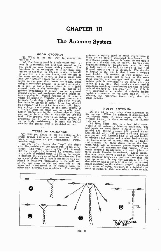
TYPES OF ANTENNAS (Q) Will you please tell me the difference be-
tween doublet and other good antennas? What types of antennas do you recommend? Please describe each.
(A) The writer favors the "zep," the single wire, Ihe doublet and the spider-web, in the order named. The "zep," shown in Fig. I1A, is much like the straight (or inverted L) antenna, save that a pair of twisted wires is used as the lead-in to decrease the pick-up of local interference. The lower end of the twisted pair is connected to a coil placed in inductive relationship to the grid coil of the first stage in the set; one side of the upper end is connected to the antenna wire, the other side, between two insulators. The straight
antenna is equally good in areas where there is little or no locally generated interference. If interference exists, the zep is better, or the lead-in may be a shielded line, as shown. In this case, impedance-matching transformers must be used at both ends of the lead, as shown in Fig. Il B if good results are to be obtained. The doublet is similar to the zep, in that it uses a twisted pair lead-in. It consists of two separate an-tennas, each usually half as long as the wave most desired, and arranged end to end. The twisted pair is connected to the inner ends, as shown in Fig. I IC. Best results are obtained if impedance-matching transformers are used at both ends of the lead-in. The spider-web, Fig. 11D, is best described as a number of different length doublets, connected to the same lead-in. It is efficient, but somewhat more costly than the other systems.
NOISY ANTENNA (Q) My set is very noisy when connected to
my antenna. When the antenna is disconnected. the signals come in much more weakly, but without noise. Is there something the matter with my aerial?
(A) Most likely there is a bad joint some. where in the system, or defective insulation. The bad joints are most likely to occur between (I) ground and ground clamp; (2) ground clamp and ground wire; (3) ground wire and ground post on set; (4) Antenna post on set and lead-in to window; (5) lead-in and window lead-in strip; (6) lead-in strip and external lead-in; (7) lead-in and antenna. All these joints (except the first. when made with an approved ground clamp) must be cleaned and soldered for best results. If an-tenna coupling transformers are used, joints to them should likewise be soldered. Leaky insula-tion may occur where a lead-in comes in contact with anything besides an insulator; see that this does not occur. It may also happen at a defec-tive window lead-in strip, or at a dirty or cracked strain insulator on the antenna proper. The most usual cause of noise, however, is a twisted (in-stead of soldered) joint somewhere in the circuit.
Fig. t t
NEW RADIO QUESTIONS & ANSWERS 13
PROTECTIVE CONDENSERS (Q) What size condenser do you recommend
for insulating aerial and ground against causing D.C. line fuses to blow?
(A) About 0.1-mf, will be quite large enough. The "operdting voltage" rating should be at least 250 volts and preferably higher.
Fig. 12
LIGHTNING ARRESTERS (Q) Are lightning arresters really necessary?
I understand that they are not used as much as formerly.
(A) It is quite true that a lower percentage of antenna installations use arresters for, if light-ning ever really strikes an antenna, the whole system is likely to fuse. But the writer strongly recommends the use of these devices for two rea-sons. First, Underwriters' regulations call for them. Second, a thunderstorm may induce a suf-ficient charge in the antenna to burn out the RS. primary coil, without lightning actually strik-ing the antenna; in this case, the arrester by' passes the charge harmlessly to ground.
— ENERGY PICK-UP
(Q) What proportion of the energy radiated from a station actually reaches my antenna?
(A) This depends upon a number of factors, including your distance from the station, the placement of your antenna, and the directive ef-fect of the station's signal, if any. A good analogy is: Consider a big stone dropped into the middle of the ocean. It causes ripples to spread out in all directions, growing weaker as their distance from the source of disturbance increases. Stick a pin into the surface of the water, and the ripples caused by the stone will affect it with about as much power as the signals of a station fifty miles away affect your antenna.
LENGTH OF ANTENNA (Q) I want to put up a plain, inverted L an-
tenna. Which is best, a long one or a short one? (A) In general, a long antenna makes the set
more sensitive; a short one makes it more selec-tive. You will have to strike a happy medium, getting the best possible sensitivity without sac-rificing selectivity to the extent that the signals of two stations interfere with each other. In gen-eral, if you are distant from powerful local sta-tions, use a long antenna; if such stations are nearby, use a short one. If you have an instruc• tion sheet with your set, follow it.
MINIMIZING INTERFERENCE (Q) A power line runs near my house. How
can I cut down interference from it? (A)Use a twisted pair or shielded lead-in, as
described earlier in this chapter. Also, locate your antenna at right angles to the power line, with the lead-in at the end furthest from the line, if this can be done conveniently.
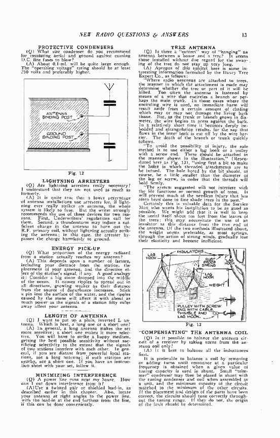
TREE ANTENNA (Q) Is there a "correct" way of "hanging" an
antenna between a house and a tree? It seems those installed without due regard for the sway- , ing of the tree do not stay up very long.
(A) Apropos of this subject here is some in-teresting information furnished by the Da%ey Tree Expert Co., as follows: "Where radio antennas are attached to trees,
the manner in which the attachment is made may determine whether the tree or part of it will be killed. Too often the antenna is fastened by means of a wire that encircles a branch or per-haps the main trunk. In those cases where the encircling wire is used, no immediate harm will result aside from a certain amount of chafing which may or may not damage the living bark tissue. But, as the trunk or branch grows in dia-meter, the wire begins to press against the bark. In a relatively short time it becomes deeply im-bedded and strangulation results, for the sap that flows in the inner bark is cut off by the wire bar-rier. The death of the branch or trunk quickly follows. "To avoid the possibility of injury, the safe
method is to use either a lag hook or a pulley with a screw end. These should be attached in the manner shown in the illustration," (Repro-duced here as Fig. 13), "using first a bit to make the holes in which threaded attachments are to be turned. The hole bored by the bit should, of course, be a little smaller than the diameter of the lag or screw, in order that the threads will hold firmly. "The system suggested will not interfere with
the life functions or normal growth of trees. It will prevent much of the needless injury that has often been done to fine shade trees in the past."
Certainly this is valuable data for the Service Man who wants his installation to be as good as possible. We might add that it is well to keep the aerial itself about ten feet from the leaves of the trees; this may necessitate the use of an insulator at this distance from the tree end of the antenna. Of the two methods illustrated above, the weight seems preferable, as most springs, through the action of strong winds, gradually lose their elasticity and become inefficient.
LAG HOOK.—
INSULATORS
RUST' LAGL PROOF HOOK SPRING
WEIGHT
:PULLEY ÇVIThSCREW ENO. WITH CABLE
_55:i—fol. TH..BLE AND LAG HOOK.
Fig. 13
"COMPENSATING" THE ANTENNA COIL (Q) Is it possible to balance the antenna cir-
cuit of a receiver by taking turns from the an-tenna coil only?
(A) It is best to balance all the inductances first.
It is preferable to balance a coil by removing or adding turns until resonance at a particular frequency is obtained when a given value of tuning capacity is used in shunt. Small "trim-mer" condenser may then be placed in shunt with the tuning condenser and coil when assembled as a unit, and the minimum capacity of the circuit matched to the minimum of the other circuits. If the placement and design of the parts have been correct, the circuits should tune correctly through-out the tuning range. If they do not, the origin of the fault should be determined.
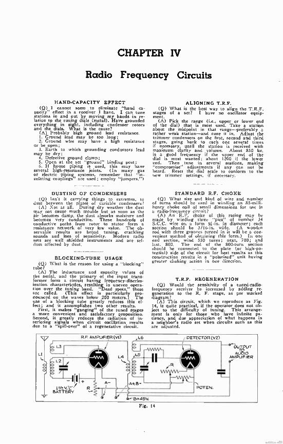
Fig. 14
CHAPTER IV
Radio Frequency Circuits
HAND-CAPACITY EFFECT (Q) I cannot seem to eliminate "hand ca-
pacity" effect in a receiver I have. I can tune stations in and out by moving my hands in re-lation to the tuning dials (metal). Have grounded everything in sight, including condenser rotors and the dials. What is the cause?
(A) Probably high ground lead resistance. 1. Ground lead may be too long; 2. Ground wire may have a high resistante
or be open; 3. Earth to which grounding conductors lead
may be dry; 4. Defective ground clamp; 5. Open at the set "ground" binding post; 6. If house piping is used, this may have
several high-resistance joints. (In many gas or electric piping systems, remember that "in-sulating couplings" are used; employ "jumpers.")
DUSTING OF CONDENSERS (Q) Isn't it carrying things to extremes, to
dust between the plates of variable condensers? (A) Not at all. During dry weather the dust
may not cause much trouble but as soon as the air becomes damp, the dust absorbs moisture and becomes very conductive. These hundreds of conductive paths from rotor to stator form a resistance network of very low value. The ob. servable results are broad tuning, crackling sounds and loss of sensitivity. Modern radio sets are well shielded instruments and are sel-dom affected by dust.
BLOCKING-TUBE USAGE (0) What is the reason for using a "blocking"
tube . (A) The inductance and capacity values of
the aerial, and the primary of the input trans-former form a circuit having frequency-discrim-ination characterictics, resulting in uneven opera-tion over the tuning band. "Dead spots," these are called. (This effect is particularly pro-nounced on the waves below 200 meters.) The use of a blocking tube greatly reduces this ef-fect; and it accomplishes two other results.
First, it makes "ganging" of the tuned stages a more convenient and satisfactory proposition. Second, it greatly reduces the radiation of in-terfering signals when circuit oscillation results d le to a "spill-over" of a regenerative circuit.
ALIGNING T.R.F. (Q) What is the best way to align the T.R.F.
stages of a set? I have no oscillator equip-ment.
(A) Pick the range (i.e., upper or lower end of the dial) that is most used. Take a station about the midpoint in that range—preferably a rather weak station—and tune it in. Adjust the trimmer condensers on the first, second and third stages, going back to each one several times if necessary, until the station is received with maximum clarity and volume. About 850 kc. is a good frequency if the upper end of the dial is most wanted; about 1200 if the lower end. Then tune in several stations, making "compromise" adjustments if any can not be heard. Reset the dial scale to conform to the new trimmer setting,, if necessary.
STANDARD R.F. CHOKE (Q) What size and kind of wire and number
of turns should be used in winding an 85-milli-henry choke coil of small dimensions for use in a radio-frequency circuit?
(A) An R.F. choke of this rating may be made by winding three "pies" of number 34 S.C.C. wire on a form ?4-in. in diameter; each section should be 3/16-in. wide. (A wooden rod with three grooves turned in it will be a con-venient method of obtaining this form.) In one end section, wind 550 turns; next, 700; and last. 800. The end of the 800-turn section should be connected to the plate (or high-po-tential) side of the circuit for best results as this construction results in a "polarized" unit having greater choking action in one direction.
T.R.F. REGENERATION (Q) Would the sensitivity of a tuned-radio•
frequency receiver be increased by adding re-generation to the R. F. stage, as per marked diagram?
(A) This circuit, which we reproduce as Fig. 14, is quite practical, if the operator does not ob-ject to the difficulty of tuning. This arrange-ment is only for those who have infinite pa-tience, and due appreciation of what happens in a neighbor's radio set when circuits such as this are adjusted.
R.F AMPLIFIER (VI) 1(.6
L5
B+45V.
DETECTOR (VZ)
POT EN.
OUTPUT TO
AUDIO AMPLIFIER
NEW RADIO QUESTIONS & ANSWERS
As to the sensitivity; it is no greater than would be that of the standard circuit if the number of turns in L4 were increased to the point of oscillation, and some oscillation control incorporated in the set. As the rotors L3 and L6 unbalance the tuning of circuits L2 and LS, a critical condition obtains; varying L3 or L6 disturbs the stability of the system again, and causes everything to go out of adjustment.
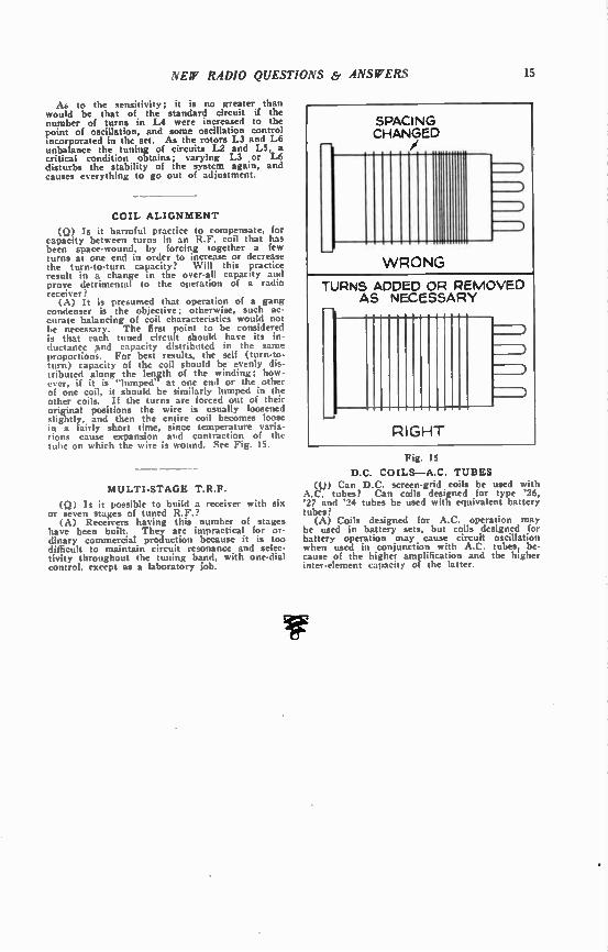
COIL ALIGNMENT
(Q) Is it harmful practice to compensate, for capacity between turns in an R.F. coil that has been space-wound, by forcing together a few turns at one end in order to increase or decrease the turn-to-turn capacity? Will this practice result in a change in the over-all capacity and prove detrimental to the operation of a radio receiver ?
(A) It is presumed that operation of a gang condenser is the objective; otherwise, such ac-curate balancing of coil characteristics would not be necessary. The first point to be considered is that each tuned circuit should have its in-ductance And capacity distributed in the same proportions. For best results, the self (turn-to-turn) capacity of the coil should be evenly dis-tributed along the length of the winding; how-ever, if it is "lumped" at one end or the other of one coil, it should be similarly lumped in the other coils. If the turns are forced out of their original positions the wire is usually loosened slightly, and then the entire coil becomes loose in a fairly short time, since temperature varia-tions cause expansion and contraction of the tube on which the wire is wound. See Fig. IS.
MULTI-STAGE T.R.F.
(Q) Is it possible to build a receiver with six or seven stages of tuned R.F.?
(A) Receivers having this number of stages have been built. They are impractical for or-dinary commercial production because it is too difficult to maintain circuit resonance and selec-tivity throughout the tuning band, with one-dial control, except as a laboratory job.
SPACING CHANGED
WRONG
TURNS ADDED OR REMOVED AS NECESSARY
GHT
Fig. IS
D.C. COILS—AC. TUBES (Q) Can D.C. screen-grid coils be used with
A.C. tubes? Can coils designed for type '26, '27 and '24 tubes be used with equivalent battery tubes?
(A) Coils designed for A.C. operation may be used in battery sets, but coils designed for battery operation may cause circuit oscillation when used in conjunction with A.C. tubes, be-cause of the higher amplification and the higher inter-element capacity of the latter.

CHAPTER V
Audio Frequency Circuits
PUSH-PULL OR PARALLEL (Q) I am planning to build an amplifier, and
want maximum output. What do you suggest, push-pull or parallel? The latter will cost me less. As it uses two tubes, it should give the same output as push-pull, but I have heard this is not the case. What are the facts?
(A) Push-pull, by all means, for it will af-ford, in many cases, about 40% more undistorted output than the same two tubes in parallel. Unless cost is a factor, consider push-pull parallel, which uses a pair of tubes in
o
Fig. 16
parallel in each side of the push-pull stage. You might also consider the use of "beam" power tubes, if the circuit you have in mind is suited to them, as to available voltages, etc.
TRANSFORMER DEFECTS (Q) In a set having low volume, I found
that placing my fingers across the first A.F. primary brought the volume up to normal. Con-tinuity tests, etc., failed to indicate any defect in the transformer. Condensers and resistors across the primary failed to be of any use. Could you explain such a case?
(A) You're lucky you didn't get a shock! It is probable that the correct voltages were
not being supplied to the tubes. Whenever a signal of even moderate amplitude reached the grid of the first A.F. tube it overloaded the grisl which, operating at the wrong point on the characteristic (for lack of sufficient "B" or "C" potential) choked up. Reducing the input by shunting the primary with a resistance kept the input to the tube within the working limits of the first stage of A.F.
16
Also, a defective transformer might cause such a condition by leakage between primary and sec-ondary, whereby the signal energy transferred is in inverse proportion to the amount of energy in the input circuit. A similar effect is some-times caused by a defective socket. It is as-sumed that the tube has been tested, or replaced, to see that it is not the source of trouble.
Connect an R.F. choke coil in the detector plate and bypass it to ground with a fixed con-denser; this unit may have a capacity of about .0005-mf. or .001-mf. The purpose is to pre-vent R.F. energy getting into the A.F. circuits. Another cause of trouble may be an open
circuit, in the primary, that is partially closed through a high resistance. Testing for con-tinuity with a high-resistance voltmeter would give an indication that might seem to indicate a perfect winding; while under the load of the tube the current passed through the circuit would be too little. Of course, a simple "cut-and-try" method of proving the case is to sub. stitute another transformer for the questionable one. If this remedies the trouble, the defective unit may be sent to the makers for test and report by their laboratories.
TONE CONTROL (Q) What is a tone control, and how does it
work? (A) It is a method of by-passing or block-
ing certain audio frequencies to prevent their reaching the reproducer. A common means of attenuating or weakening the highs is to con-nect a fixed condenser and variable resistor (values may be .01 mf. and 500,000 ohms) across the primary of the first audio transformer. The lows may be blocked by means of a fixed con-denser in series with a speaker lead. A switch-ing system, used with a number of fixed con-densers of various values, permits the degree of bass attenuation to be controlled. See Fig. 17.
Fig. 17
SCRATCH FILTER (Q) In a radio phonograph, what is a scratch
filter, to remove needle noise? (A) It is merely a fixed tone control or filter,
set to cut off the highs. A .02-mf. condenser in series with a 25,000-ohm resistor, connected across the pick-up will do it. It will also elimin-ate the high notes, however, and it is suggested that a variable resistor of 250,000 ohms be used in placed of the fixed one.
NEW RADIO QUESTIONS & ANSWERS 17
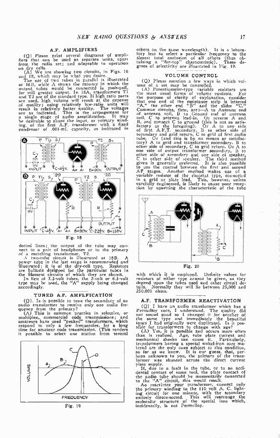
A.F. AMPLIFIERS (Q) Please print several diagrams of ampli-
fiers that can be used as separate units, apart from the radio set; and adaptable to operation on dry cells.
(A) We are showing two circuits. in Figs. 16 and 18, which may be what you desire. The use of two tubes in parallel is illustrated
at 16B, while A shows the manner in which the output tubes would be connected in push-pull, for still greater output. In 18A, transformers T1 and T2 are of the standard type. If high ratio parts are used, high volume will result at the expense of quality; using relatively low-ratio units will result in relatively better quality. The voltages are as indicated. This is the arrangement for a single stage of audio amplification. It may be desirable to shunt the input, or primary wind-ing, of the first A.F. transformer with a fixed condenser of .001-mf, capacity, as indicated in
e 5i
nn uu
INPUT C-44V. A+ A- 5;-90V °UTPUT
0 I, r s '99 '20 TZ 5
INPUT C
OUTPUT I
V. elk- 4+ 8;90V. C-22. B+1";;V.
F:g. 18
dotted lines; the output of the tube may con-nect to a pair of headphones or to the primary of a matching transformer, T2. A two-tube circuit is illustrated at 18B. A
power tube in the last stage is recommended and illustrated; it is of the dry-cell type. Resistors are ballasts designed for the particular tubes in the filament circuits of which they are shown.
In lieu of 3.3-volt tubes, the 2-volt or 6.3-volt type may be used, the "A" supply being changed accordingly.
TUNED A.F. AMPLFICATION (9). Is is possible to tune the secondary of an
audio transformer to receive only one audio fre-quency from the primary?
(A) This is common practice in selective, or multiplex, commercial code transmissions; and amateurs ht.ve used "peaked" transformers, which respond to only a few frequencies, for a long eme for amateur code transmission. (This renders it possible to select one station from several
Fig. 19
others on the same wavelength). It is a labora-tory feat to select a particular frequency to the almost total exclusion of all others (thus ob-taining a "flat-top" characteristic). These de-grees of selectivity are illustrated in Fig. 19.
- - - - VOLUME CONTROL
(Q) Please mention a few ways in which vol-ume of a set may be controlled.
(A) Potentiometer-type variable resistors are the most usual forms of volume controls. For the purpose of clarity of explanation, consider that one end of the resistance strip is lettered "A," the other end "B" and the slider "C." Common circuits, then, are:—A to Antenna end of antenna coil, B to Ground end of antenna coil, C to antenna lead-in. Or reverse A and B, and connect C to ground (this is not as satis-factory as the foregoing). Or A to one side of first A.F.T. secondary, B to other side of secondary and grid return, C to grid of first audio tube. Or (and this is by no means as satisfac-tory) A to grid and transformer secondary, B to other side of secondary, C to grid return. Or A to one side of output transformer secondary, B to other side of secondary and one side of speaker, C to other side of speaker. The third method given is generally preferred. It is also possible to use the control between the first and second AF stages. Another method makes use of a variable resistor of the rheostat type, connected in a grid or plate lead. This, however, unless carefully engineered, is likely to cause poor recep-tion by upsetting the characteristic of the tube
Fig 20
with which it is employed. Definite values for resistors of either type cannot be given, as they depend upon the tubes used and other circuit de-tails. Normally they will lie between 25,000 and 250,000 ohms.
A.F. TRANSFORMER REACTIVATION (Q) I have an audio transformer which has a
Permalloy core, I understand. The quality did not sound good so I changed it for another of the same type and immediately the beautiful tones I had originally were duplicated. Is it pos-sible for transformers to change with age?
(A) Yes, it is possible and occurs more often than is realized. Age, tube plate current and mechanical shocks can cause it. Particularly, transformers having a special nickel-iron core ma-terial are the only ones subject to this condition, so far as we know. It is our guess, that, per-haps unknown to you, the primary of the trans-former was shunted across the direct current plate supply.
If, due to a fault in the tube, or to an acci-dental contact of some tool, the plate contact of the audio tube should be momentarily connected to the "A" circuit, this would result. Ao reactivate your transformer, connect only
the primary winding to the 110 volt A. C. light-ing circuit for one minute, with the secondary entirely disconnected. This will rearrange the molecular structure of the special iron which, incidentally, is not Permalloy.
CHAPTER VI
Reproducers
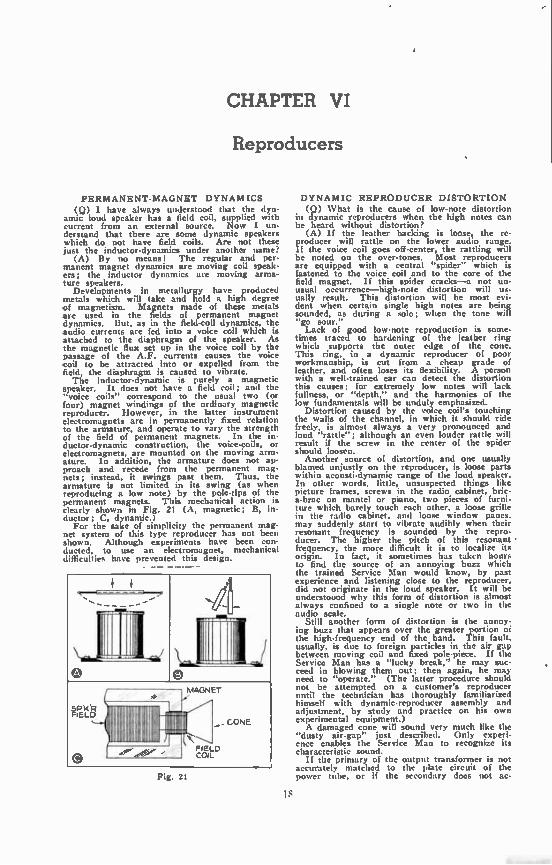
PERMANENT-MAGNET DYNAMICS (Q) I have always understood that the dyn-
amic loud speaker has a field coil, supplied with current from an external source. Now I un-derstand that there are some dynamic speakers which do not have field coils. Are not these just the inductor-dynamics under another name?
(A) By no means! The regular and per-manent magnet dynamics are moving coil speak-ers; the inductor dynamics are moving arma-ture speakers.
Developments in metallurgy have produced metals which will take and hold a high degree of magnetism. Magnets made of these metals are used in the fields of permanent magnet dynamics. But, as in the field-coil dynamics, the audio currents are fed into a voice coil which is attached to the diaphragm of the speaker. As the magnetic flux set up in the voice coil by the passage of the A.F. currents causes the voice coil to be attracted into or expelled from the field, the diaphragm is caused to vibrate. The inductor-dynamic is purely a magnetic
speaker. It does not have a field coil; and the "voice coils" correspond to the usual two (or four) magnet windings of the ordinary magnetic reproducer. However, in the latter instrument electromagnets are in permanently fixed relation to the armature, and operate to vary the strength of the field of permanent magnets. In the in-ductor-dynamic construction, the voice-coils, or electromagnets, are mounted on the moving arm-ature. In addition, the armature does not ap-proach and recede from the permanent mag-nets; instead, it swings past them. Thus, the armature is not limited in its swing (as when reproducing a low note) by the pole-tips of the permanent magnets. This mechanical action is clearly shown in Fig. 21 (A, magnetic; B, in-ductor; C, dynamic.)
For the sake of simplicity the permanent mag-net system of this type reproducer has not been shown. Although experiments have been con-ducted, to use an electromagnet, mechanical difficulties have prevented this design.
- - -
.../. , \-7-
o
mg., II , \i, . o .1
V-1GN ET
FtELO
\
,,- CONE
FIELD COIL
(9 -1
Fig. 21
Is
DYNAMIC REPRODUCER DISTORTION (Q) What is the cause of low-note distortion
in dynamic reproducers when the high notes can be heard without distortion?
(A) If the leather backing is loose, the re-producer will rattle on the lower audio range. If the voice coil goes off-center, the rattling will be noted on the over-tones. Most reproducers are equipped with a central "spider" which is fastened to the voice coil and to the core of the field magnet. If this spider cracks—a not un-usual occurrence—high-note distortion will us-ually result. This distortion will be most evi-dent when certain single high notes are being sounded, as during a solo; when the tone will "go sour." Lack of good low-note reproduction is some-
times traced to hardening of the leather ring which supports the outer edge of the cone. This ring, in a dynamic reproducer of poor workmanship, is cut from a cheap grade of leather, and often loses its flexibility. .A person with a well-trained ear can detect the distortion this causes; for extremely low notes will lack fullness, or "depth," and the harmonics of the low fundamentals will be unduly emphasized.
Distortion caused by the voice coil's touching the walls of the channel, in which it should ride freely, is almost always a very pronounced and loud "rattle"; although an even louder rattle will result if the screw in the center of the spider should loosen.
Another source of distortion, and one usually blamed unjustly on the reproducer, is loose parts within acousti-dynamic range of the loud speaker. In other words, little, unsuspected things like picture frames, screws in the radio cabinet, bric-a-brac on mantel or piano, two pieces of furni-ture which barely touch each other, a loose grille in the radio cabinet, and loose window panes. may suddenly start to vibrate audibly when their resonant frequency is sounded by the repro-ducer. The higher the pitch of this resonant • frequency, the more difficult it is to localize its origin. In fact, it sometimes has taken hours to find the source of an annoying buzz which the trained Service Man would know, by past experience and listening close to the reproducer, did not originate in the loud speaker. It will be underst000d why this form of distortion is almost always confined to a single note or two in the audio scale.
Still another form of distortion is the annoy-ing buzz that appears over the greater portion oi the high-frequency end of the band. This fault, usually, is due to foreign particles in the air gap between moving coil and fixed pole-piece. If the Service Man has a "lucky break," he may suc-ceed in blowing them out; then again, he may need to "operate." (The latter procedure should not be attempted on a customer's reproducer until the technician has thoroughly familiarized himself with dynamic-reproducer assembly and adjustment, by study and practice on his own experimental equipment.) A damaged cone will sound very much like the
"dusty air-gap" just described. Only experi-ence enables the Service Man to recognize its characteristic sound.
If the primary of the output transformer is not accurately matched to the plate circuit of the power tithe, or if the secondary does not Sc-
NEW RADIO QUESTIONS & ANSWERS 19
curately match the voice-coil winding, very pro-nounced distortion may result. This may take the form in insufficient bass reproduction, or "fuzzy" high-register notes.
- - - BINAURAL RECEPTION
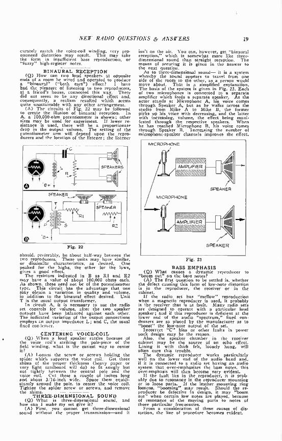
(Q) How can two loud speakers at opposite ends of a room be wired and operated to produce a "binaural" ("both ears") effect? I have had the pleasure of listening to two reproducers, at a friend's house, connected this way. There did not seem to be any directional effect and, consequently, a realism resulted which seems quite unattairable with any other arrangement. (A) The drcuits of Fig. 22 may be followed
to create the illusion of binaural reception. In A, a 100,000 ohm potentiometer is shown; other sizes may be used for experiment. If lower re-sistance is used, there will be a proportionate drop in the output volume. The setting of the rotentiometer arm will depend upon the repro-ducers and the location of the listener; the listener
Fig. 22
should, preferably, be about half-way between the two reproducers. These units may have similar, or dissimilar characteristics, as desired. One peaked for the highs, the other for the lows, gives a good effect. The resistors indicated in B as RI and R2
may have a value of about 100,000 ohms each. As shown, these need not be of the potentiometer type. This circuit has the advantage that one may obtain a variation in quality and volume, in addition to the binaural effect desired. Unit T is the usual output transformer.
In circuit A, it is necessary to use the radio set controls for volume, after the two speaker outputs have been balanced against each other. The indicated variation of the output connections employs zn output impedance L; and C, the usual fixed con-lenser.
CENTERING VOICE-COIL • (Q) When a loud speaker rattles because of
the voice coil's striking the pole-piece of the field winding, what is the easiest way to center it?
(A) Loosen the screw or screws holding the spider which supports the voice coil. Get three shims of the proper thickness (heavy paper or very light cardboard will do) to fit snugly but not tightly between the central pole and the voice coil. Cut these a couple of inches long and about 3/16-inch wide. Space them equidi-stantly around the pole, to center the voice coil. Tighten the spider screw or screws, and remove the shims. - ---
THREE-DIMENSIONAL SOUND (Q) What is three-dimensional sound, and
how can I make my set give it? (A) First, you cannot get three-dimensional
sound without the proper transmission—and it
isn't on the air. You can, however, get "binaural reception," which is somewhat more like three-dimensional sound than straight reception. The means of securing it is given in the answer to the next question. As to three-dimensional sound— it is a system
whereby the sound appears to travel from one side of the room to the other, as a person would move about. That is a simplified explanation. The basis of the system is given in Fig. 23. Each of two microphones is connected to a separate amplifier which feeds a separate speaker. As the actor stands at Microphone A, his voice comes through Speaker A, but as he walks across the studio from Mike A to Mike B, the former picks up his voice with decreasing, and the latter with increasing, volume, the effect being mani-fested through the respective speakers. When he has reached Microphone B, his voice comes through Speaker B. Increasing the number of microphone-speaker channels improves the effect.
MICROPHONE
SPEAKER
MICROPHONE
e AMPLIFIER
g A
SPEAKER
Fig. 23
BASS EMPHASIS (Q) What causes a dynamic reproducer to
"boom out" on the bass notes? (A) The first question to be settled is, whether
the defect causing this form of low-note distortion is in the reproducer, the receiver or in the cabinet.
If the radio set has "mellow" reproduction when a magnetic reproducer is used, it probably is the receiver that is at fault. Many radio sets are designed to operate with a particular loud speaker; and if this reproducer is deficient at the lower end of the audio "spectrum," fixed con-densers are so placed by the manufacturer as to "boost" the low-note output of the set.
Incorrect "C" bias or other faults in power pack design may be the reason.
Also, the speaker chamber in the receiver cabinet may be the source of an echo effect. Lining it with thick felt, loosely hung, will often cure this trouble. The dynamic reproducer works particularly
well on the lower end of the audio band and, if it is connected to a radio set having an audio system that over-emphasizes the bass notes, this over-emphasis will then become very evident.
If the fault lies in the reproducer, it is prob-ably due to resonance in the reproducer mounting or to loose parts. If the leather mounting ring loosens, "booming" may result. Should the re-producer be defective in design, it may "boom out" when certain low notes are played, because of resonance of the moving parts to notes of those particular frequencies. From a consideration of these causes of dis-
tortion, the line of procedure becomes evident.
CHAPTER VII
Power Supplies
2$ or 60 CYCLES? (0) Can an electric set be used on 25-or 60-
cycle supply, optionally? If not why not? (A) A radio set designed to be used with
60-cycle supply cannot, except by special design, be used with 25-cycle current supply. The 25-cycle supply changes polarity very slow-
ly, as compared to 60-cycle supply and the lower impedance at this frequency permits a much greater current flow in power transformer wind-ings, which causes them to heat to a high degree. In fact, the primary of a transformer designed for 60-cycle operation would probably burn out.
It is easier to filter properly 60-cycle current than 25-cycle current. For the latter, it is necessary to double or triple the capacity values of the units in the filter condenser bank, and generally to increase the inductance of the choke coils. A power transformer designed for 25-cycle
supply must be substituted for the 60-cycle trans-former. If a current-regulating line ballast is used, this must be changed for one having the correct value.
Ordinarily, a 25-cycle set will work very well, and usually with less hum than a 60-cycle receiver, when connected to a 60-cycle current supply of the same voltage rating.
CHOKES IN POWER PACKS (Q) Why do some power packs have choke
coils in them and others not? Why don't they all use chokes if chokes are needed, and why do any of them use chokes if chokes are unneces-sary?
(A) It is a matter of circuit design. Some sets use chokes, others use the field coil of the dynamic speaker as a choke, and still others merely employ greater capacity condensers. All these systems work satisfactorily.
Fig. 24
20
INCREASING "B" VOLTAGE (0). What is necessary to change a "B" elim-
inator to deliver 250 volts instead of 180? (A) The solution of that problem is to rebuild
it completely. A scheme sometimes employed to increase voltage is to change the rectifier for one of higher output rating. However, this puts an added strain on the transformer, granting that the condenser pack has been changed for one having a higher break-down rating; and a burned-out transformer may result. Use a higher voltage transformer and condensers, and what-ever resistors are required for the voltage taps you need. You can still use the same filter chokes, however. A modern rectifier tube, adequate to whatever output you need, should also be used.
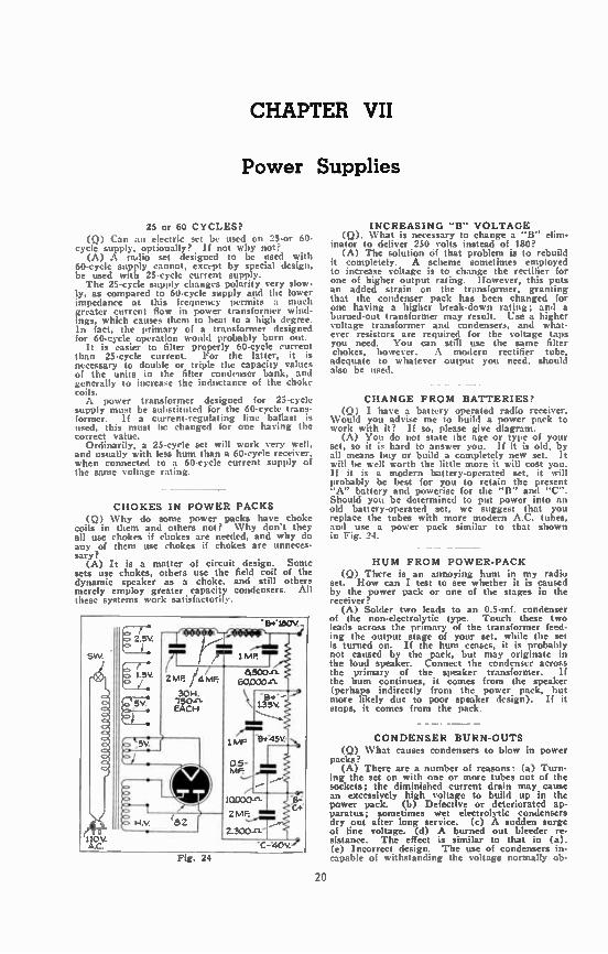
CHANGE FROM BATTERIES? (Q) I have a battery operated radio receiver.
Would you advise me to build a power pack to work with it? If so, please give diagram.
(A) You do not state the age or type of your set, so it is hard to answer you. li it is old, by all means buy or build a completely new set. It will be well worth the little more it will cost you. If it is a modern battery-operated set, it will probably be best for you to retain the present "A" battery and powerise for the "B" and "C". Should you be determined to put power into an old battery-operated set, we suggest that you replace the tubes with more modern A.C. tubes, and use a power pack similar to that shown in Fig. 24.
HUM FROM POWER-PACK (Q) There is an annoying hum in my radio
set. How can I test to see whether it is caused by the power pack or one of the stages in the receiver?
(A) Solder two leads to an 0.5-mf, condenser of the non-electrolytic type. Touch these two leads across the primary of the transformer feed-ing the output stage of your set, while the set is turned on. If the hum ceases, it is probably not caused by the pack, but may originate in the loud speaker. Connect the condenser across the primary of the speaker transformer. If the hum continues, it comes from the speaker (perhaps indirectly from the power pack, but more likely due to poor speaker design). If it stops, it comes from the pack.
CONDENSER BURN-OUTS (Q) What causes condensers to blow in power
packs? (A) There are a number of reasons: (a) Turn-
ing the set on with one or more tubes out of the sockets; the diminished current drain may cause an excessively high voltage to build up in the power pack. (b) Defective or deteriorated ap-paratus; sometimes wet electrolytic condensers dry out after long service. (c) A sudden surge of line voltage. (d) A burned out bleeder re-sistance. The effect is similar to that in (a). (e) Incorrect design. The use of condensers in-capable of withstanding the voltage normally ob-

NEW RADIO QUESTIONS & ANSWERS
tamed from the pack (for instance the use of a condenser rated for a peak voltage of 400, where one with a working voltage of 400 should have been used). There are also other causes, but these are the most common.
CONNECTING TWO "B" UNITS
(Q) Can two "B" eliminators, each delivering 180 volts, be hooked up to deliver 360 volts? (A) Yes, the highest positive lead of the first
unit being joined to the negative lead of the second. But be careful not to connect the grounds in such a way that a short circuit may result. For ..aiety, use a .1 mfd. fixed condenser in series with each ground. See Fig. 25.
Before connecting the increased output to a receiver, the latter should be examined to de-termine whether the by-pass condensers within the set, from "B plus max" to "B—" are capable of operating at the increased potential.
"B' ELIMINATORS
Fig. 25
RECEIVER OPERATION COST
(Q) What is the cost of current per month for operating a 75-watt radio set?
(A) Find the total wattage required to oper-ate the set for an average month, and find the relation this figure bears to 1,000 watts—the usual basis on which the current cost is rated. For example: the receiver is operated on an
average of four hours every day, requiring a total current approximately 9,000 watt-hours (I watt used for 1 hour equals I watt-hour) per month. This is nine times 1,000 watt-hours. In some locaiities the charge is "ten cents per kilowatt-hour (1,000 watt-hours)" and this would make the cost of operation 90 cents per Month.
GASEOUS-RECTIFIER "B" UNIT
(Q) I have a "II" eliminator of the type shown in Fig. 21. Please advise the range of the two variable resistors.
(A) Two "universal range" resistors are used in this "B" eliminator, in the positions shown
21
in the schematic diagram (Fig. 26). The recti-fier is a "BH" or gaseous-type tube. The power-line resistor may be set to take care of differences in line-voltage. Resistor RI measures 200 ohms.
Fig. 26
"C" FROM "B" UNIT (9) Please advise me as to whether a "B"
eliminator can be wired to supply the "C" bias for a '71 A power tube and also a 4%-volt bias. An eliminator in question supplies 60 milliam-peres at 180 volts.
(A) A 2000-ohm resistor, connected between the center-tap of the power transformer second-ary and the negative terminal of the power unit, will supply the required bias for a '71A tube. The center-tap is now "C" minus and the reg-ular "B" minus post is now also the "C" plus connection. If the resistor is equipped with a sliding contact, the bias may be varied and, if two contacts are provided, the 41% volts negative required as the bias potential for '01A-type tubes may also be obtained. When securing a bias voltage in this manner,
the "C" voltage is obtained at the expense of the "B" voltage; and causes a corresponding re-duction in the total "B" available.
See Fig. 27 for the general idea.
Fig. 27
CHAPTER VIII
Superheterodyne Receivers
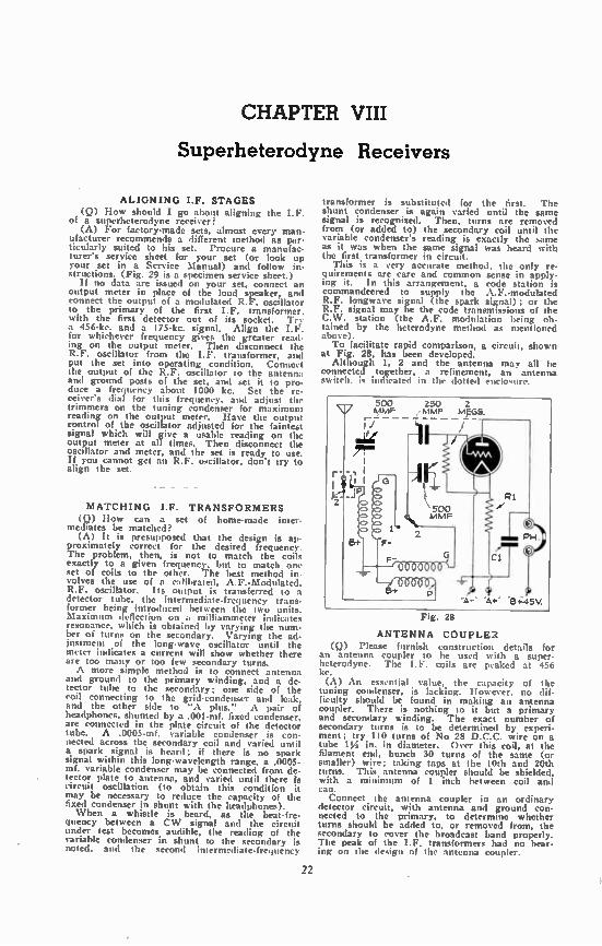
ALIGNING I.F. STAGES (Q) How should I go about aligning the I.F.
of a superheterodyne receiver? (A) For factory-made sets, almost every man-
ufacturer recommends a different method as par-ticularly suited to his set. Procure a manufac-turer's service sheet for your set (or look up your set in a Service Manual) and follow in-structions. (Fig. 29 is a specimen service sheet.)
If no data are issued on your set, connect an output meter in place of the loud speaker, and connect the output of a modulated R.F. oscillator to the primary of the first I.F. transformer, with the first detector out of its socket. Try a 456-kc. and a 175-kc. signal. Align the LP. for whichever frequency gives the greater read-ing on the output meter. Then disconnect the R.F. oscillator from the I.F. transformer, and put the set into operating condition. Connect the output of the R.F. oscillator to the antenna and ground posts of the set, and set it to pro-duce a frequency about 1000 kc. Set the re-ceiver's dial for this frequency, and adjust the trimmers on the tuning condenser for maximum reading on the output meter. Have the output control of the oscillator adjusted for the faintest signal which will give a usable reading on the output meter at all times. Then disconnect the oscillator and meter, and the set is ready to use. If you cannot get an R.F. oscillator, don't try to align the set.
MATCHING I.F. TRANSFORMERS (Q) 'low can a set of home-made inter-
mediates be matched? (A) It is presupposed that the design is ap-
proximately correct for the desired frequency. The problem, then, is not to match the coils exactly to a given frequency, but to match one set of coils to the other. The best method in-volves the use of a calibrated, A.F.-Modulated. R.F. oscillator. Its output is transferred to a detector tube, the intermediate-frequency trans-former being introduced between the two units. Maximum deflection on a milliammeter indicates resonance, which is obtained by varying the num-ber of turns on the secondary. Varying the ad-justment of the long-wave oscillator until the meter indicates a current will show whether there are too manv or too few secondary turns. A more simple method is to connect antenna
and ground to the primary winding, and a de-tector tube to the secondary; one side of the coil connecting to the grid-condenser and leak, and the other side to "A plus." A pair of headphones, shunted by a .001-mf, fixed condenser, are connected in the plate circuit of the detector tube. A .0005-mf. variable condenser is con-nected across the secondary coil and varied until a spark signal is heard; if there is no spark signal within this long-wavelength range, a .0005-inf. variable condenser may be connected from de-tector plate to antenna, and varied until there circuit oscillation (to obtain this condition it may be necessary to reduce the capacity of the fixed condenser in shunt with the headphones). When a whistle is heard, as the beat-fre-
quency between a CW signal and the circuit under test becomes audible, the reading of the variable condenser in shunt to the secondary is noted, and the second intermrdiate-frequency
22
titinsiui nit r is substituted for the first. The shunt condenser is again varied until the same signal is recognized. Then, turns are removed from (or added to) the secondary coil until the variable condenser's reading is exactly the same as it was when the same signal was heard with the first transformer in circuit.
This is a very accurate method, the only re-quirements are care and common sense in apply-ing it. In this arrangement, a code station is commandeered to supply the A.F. -modulated R.F. longwave signal (the spark signal); or the R.F. signal may be the code transmissions of the C.W. station (the A.F. modulation being ob-tained by the heterodyne method as mentioned above). To facilitate rapid comparison, a circuit, shown
at Fig. 28, has been developed. Although 1, 2 and the antenna may all be
connected together, a refinement, an antenna switch, is indicated in the dotted enclosure.
Fig. 28
ANTENNA COUPLER (Q) Please furnish construction details for
an antenna coupler to be used with a super-heterodyne. The I.F. coils are peaked at 456 kc. (A) An essential value, the capacity of the
tuning condenser, is lacking. However, no dif-ficulty should be found in making an antenna coupler. There is nothing to it but a primary and secondary winding. The exact number of secondary turns is to be determined by experi-ment; try 110 turns of No 28 D.C.C. wire on a tube 1 y2 in. in diameter. Over this coil, at the filament end, bunch 30 turns of the same (or smaller) wire; taking taps at the 10th and 20th turns. This antenna coupler should be shielded, with a minimum of 1 inch between coil and can.
Connect the antenna coupler in an ordinary detector circuit, with antenna and ground con-nected to the primary, to determine whether turns should be added to, or removed from, the secondary to cover the broadcast band properly. The peak of the IF. transformers had no bear-ing on the design of the antenna coupler.

NEW RADIO QUESTIONS & ANSWERS 23
Radio Service Data Sheet 217
SPARTON SELECTRONNE RECEIVERS MODELS 1068 AND 1068X ID-tube experhatetodyne three bands; froth-button (5.1.clif 01 tuning: automatic hstelnt,c, control: automat.< xedurne enntrcd:
discrieni aaaaa circesit; "ris-o-glote" Inning indic•for.
(See Data Sheet 218 for schematic diagram and operating robot...)
The C bid.nt of the Relre-tronne are in 2
."..• .``.'en. n. '''''' SeleCrennue )RIMMER{ .
e .........
HC) •
il
., II . i
ou: t
gib' 0
L ..... ____.,,.1111111MijIhil'
i fil:11e .-'1
.....
0.
P I
Id
e orti 4.,
enters, Innate-612 te, a00 Fr . 200 to 1.200 I.e.. and 1.00n to 1.200dina ke. The 4 tams eorre. mon to the deoired on. lion, nowt be «ranee) In the ateel ',late m that raeh atallon frenuenee oat be in• eluded in the p.n., fr.• nuenee cowls. To ahan. mix', in the Seleetronne button win h corn...condo t., the de. aired statton and ',clout f. r maximum manor,. •• ,"• cheated ba the Vuo-Clo tt.be. the 'Marlin. 'sentience Is, t .1 mediator trimmer terrier bole), 121 heat R m .F. trtrner 'button hole). •nd 121 nn• nn• trimmer ono ,
' teThe Vim.Glo tubehole and ...bet min, be .rernesed from
C
C
C
50
SI
S1
I
(ANT.) ....
(05C3 -- ••. „
(0•0) ••..
•,,
)
•
C 47 AB C ‘Ii5A8
C 49 A C 49 a
CI 1.
.....---t I ,.
litilingnilligji 4 „........,
----- , ...."2. F - ---'t --- - I
ft lame d th I be t I toward the bxek of the an hinm for obwr,a ti,,,, s At. ele...wl It> xpolcine a MAt ere—ore tit the lincer• under Orr lt,„, Reseet ,„,, ne trimmer. latehine band almh rune aer...e the fr.tmenork in front of Ow foe !maxi shaded area with rtnoner boa. Care Mould be taken to ',recent krownina th band munch knob either in 'eleeleenne ad'ustinc wren. to the moist where the, may Imwn,
or out. DurInc above opera. wentramd. llora the GIIGG disernrunator The above.mentioned latch,re bar l• ....en in the ohetweranl, o
Th., Wain, bar, ..,,.n ma, tom se,.‘„ .... r.‘....r. ....., am ntimmt.tinn latatt p..01. b„,,, ,,,,,.... Toe hem o oytteeno right of Mil page is a tea iew of the locations of the Inmenart toe the .n ,., buttons en:we, ix t`• •bam ',WM xi•w
of this rime.,
ta removed from Malin.. In he luttions of the Selertrunne tramment. or the went that all I Sam- he boons of the Week thit camel the Seleetronne trimmer,. I. in teem., button» become de- irest hne wnh the •rrow thet swim., to Sekwtwone tronmem Ct ore...ed throuth Improper (ow.) t • mrner el the Intehina tr.tr extend. neat the red, ii.4.:h
tw,unedat, ,n they mar be edc, uf the leonine,. Pero,
Vieo-Clo tube in soceet
AFC Snitch OFF'
ALIGNMENT
OPIO- AT1011
ALIGIOCIDIT or
GENERATOR CONNECTED
TO
DU100r MTENIIA
GENERATOR FREQUENCY
BIND SWITCH smnic
11111111G COND. SETTING
TRIMIER RFRAFUIS
C47 A,B let T.F. Trans.
1 I.F. Caw. Grid .1 nt. 456 BC OPee C48 A,B 7nd I.F. Trena.
C48 a Sod I.F. (Pri.)
2 Dlecrin. Cony. Grid .1 et. 456 BC Open 049 13 Adjust to nininun
C8 OeC.
8c Isoo C5 RF $ Broadcast
Band Ant. 200 nat. 1500
C2 Ant.
4 Ant. 200 met. 600 BC 600 CII Pad
5 (Repeat operation 5)
6 (Che k calibration and sensitivity 1500 IC 900 KC and 600 [C) •
100 ohm C9 Oac.
7 let Short Ant. 200 ..f. e MC. 1st S.l. 6 mc Cs OF
Wave mrleig CS Mt.
8 Ant. 205 mt. 1.95 MC. Sat S.W. 1.95 MC. Cl2 Red
9 (Repent operation 7) 10 (Cheek calibration and eernitivity at 6 RC. and 1.95 NC.)
100 ohm CIO Oec.
11 End Short- Ant. 200 nat. 18 MC. End S.W. 18 MC. Cl R.F. Rock dial alightly
Wave aeries C4 Ant. while sdjusting
12 Rand
Ant. 6 MC. 2nd S.W. 6 MC. CIS Pad
15 (Repeat operation 11)
14 (Check calibration and een itivity at 18 WC. and 6 NC.)
15 (Repeat operation* 1 to 14 imlueive)
• Check AFC by connecting generator to converter grid cep and tuning generator and roc..... to 1500 EC. Mote output meter reading with AFC switch *off'. Switch Alt no8. ...I if output cleaves appreciably, touch up discriainator triener until there ja no change in eenettivity.
Fig. 29
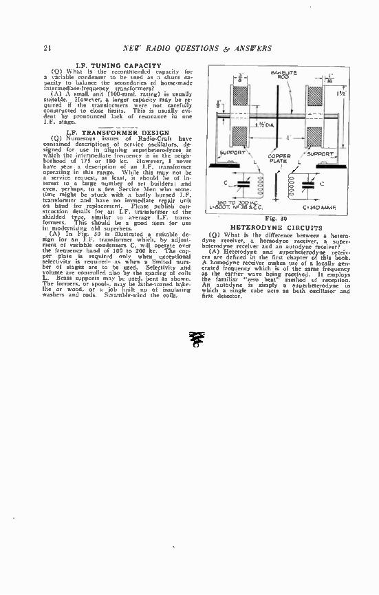
24 NEW RADIO QUESTIONS 6, ANSWERS
I.F. TUNING CAPACITY (Q) What is the recommended capacity for
a variable condenser to be used as a shunt ca-pacity to balance the secondaries of home-made intermediate-frequency transformers?
(A) A small unit (100-mmf. rating) is usually suitable. However, a larger capacity may be re-quired if the transformers were not carefully constructed to close limits. This is usually evi-dent by pronounced lack of resonance in one I.F. stage.
— - I.F. TRANSFORMER DESIGN
(Q) Numerous issues of Radio-Craft have contained descriptions of service oscillators, de-signed for use in aligning superheterodynes in which the intermediate frequency is in the neigh-borhood of 175 or 180 kc. However, I never have seen a description of an I.F. transformer operating in this range. While this may not be a service request, at least, it should be of in-terest to a large number of set builders; and even, perhaps, to a few Service Men who some-time might be stuck with a badly burned I.F. transformer and have no immediate repair unit on hand for replacement. Please publish con-struction details for an I.F. transformer of the shielded type, similar to average IF. trans-formers. This should be a good item for use in modernizing old superhets.
(A) In Fig. 30 is illustrated a suitable de-sign for an I.F. transformer which, by adjust-ment of variable condensers C, will operate over the frequency band of 100 to 200 kc. The cop-per plate is required only when exceptional selectivity is required- as when a limited num-ber of stages are to be used. Selectivity and volume are controlled also by the spacing of coils L. Brass supports may be used, bent as shown. The formers, or spools, may be lathe-turned bake-lite or wood, or a job built up of insulating washers and rods. Scramble-wind the coils.
Fig. 30
HETERODYNE CIRCUITS (Q) What is the difference between a hetero-
dyne receiver, a homodyne receiver, a super-heterodyne receiver and an autodyne receiver?
(A) Heterodyne and superheterodyne receiv-ers are defined in the first chapter of this book. A homodyne receiver makes use of a locally gen-erated frequency which is of the same frequency as the carrier wave being received. It employs the familiar "zero beat" method of reception. An autodyne is simply a superheterodyne in which a single tube acts as both oscillator and first detector.
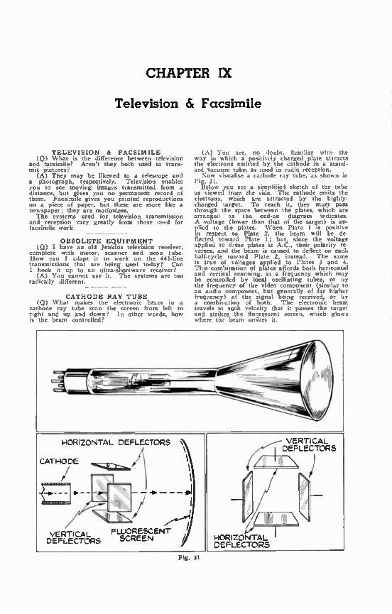
CHAPTER IX
Television & Facsimile
TELEVISION & FACSIMILE (Q) What is the difference between television
and facsimile? Aren't they both used to trans-mit pictures?
(A) They may be likened to a telescope and a photograph, respectively. Television enables you to see moving images transmitted from a distance, but eves you no permanent record of them. Facsimile gives you printed reproductions on a piece of paper, but these are more like a newspaper; they are motionless. The systems used for television transmission
and reception vary greatly from those used for facsimile work.
OBSOLETE EQUIPMENT (Q) I have an old Jenkins television receiver,
complete with motor, scanner and neon tube. How can I adapt it to work on the 441-line transmissions that are being used today? Can I hook it up to an ultra-shortwave receiver?
(A) You cannot use it. The systems are too radically different.
CATHODE RAY TUBE (Q) What makes the electronic beam in a
cathode ray tube scan the screen from left to right and up and down? In other words, how is the beam controlled?
(A) You are, no doubt, familiar wilt the way in which a positively charged plate attracts the electrons emitted by the cathode in a stand-ard vacuum tube, as used in radio reception. Now visualise a cathode ray tube, as shown in
Fig. 31. Below you see a simplified sketch of the tube
as viewed from the side. The cathode emits the electrons, which are attracted by the highly-charged target. To reach it, they must pass through the space between the plates, which are arranged as the end-on diagram indicates. A voltage (lower than that of the target) is ap-plied to the plates. When Plate I is positive in respect to Plate 2, the beam will be de-flected toward Plate 1; but, since the voltage applied to these plates is A.C., their polarity re-verses, and the beam is caused to deflect on each half-cycle toward Plate 2, instead. The same is true of voltages applied to Plates 3 and 4. This combination of plates affords both horizontal and vertical scanning, at a frequency which may be controlled by local oscillating tubes, or by the frequency of the video component (similar to an audio component, but generally of far higher frequency) of the signal being received, or by a combination of both. The electronic beam travels at such velocity that it passes the target and strikes the fluorescent screen, which glows where the beam strikes it.
Fig. 31

26 NEW RADIO QUESTIONS ¡sr A ERS
Fig. 32. Television Image
CAN'T BUILD EQUIPMENT (Q) How can 1 build a facsimile reproducer
to connect to my present set, so that I can pick up the transmissions of the broadcasting stations that are putting out facsimile programs?
(A) Facsimile equipment is not of a nature adapted to construction in the home workshop. You will have to wait until you can buy the reproducer.
— FACSIMILE OPERATION
( Q ) How does a facsimile reproducer op-erate?
(A) There are several systems. In all, as-sume that there is an electro-mechanical means of causing a stylus, or similar device, to pass across a sheet of paper in synchronism with a scanner at the transmitter, and of causing it to progress one line in relation to the paper at the end of each complete traversal. Various means of securing this action are used in the different systems. The other function is to cause the stylus to
make marks on the paper, in accordance with the signal transmitted. Several methods of achieving this end are in use. One employs a stylus which is similar in action to the drive-rod of a magnetic loud speaker; the vibrating rod, driven by signal impulses, strikes against a piece of carbon paper, causing marks to be imprinted on a plain piece of paper. In other
ÈXPERIMENTAL
FACSIM!LE
— Lee's Army Burnside> Arts_tyi
Fig. 33. Facsimile Picture
systems, the paper is impregnated with chemi-cals that aie discolored (or eradicated) by the passage of electric current; the stylus forms one pole of a circuit and a plate behind the paper is the other; the current is controlled by the incoming signal. Tiny ink-sprays with elec-trically controlled deflectors, and other systems, have also been used.
LARGE-PICTURE TELEVISION (Q) Why is it impossible to have a sheet
several feet square and covered with fluorescent material, and to hang this some distant in front of the television receiver, and have a clear glass end in the cathode-ray tube, so that the elec-trons could be projected right to the big screen? If it is not impossible, why is it not being done?
(A) Air is a complex gas, and electrons can-not pass through it freely. A cathode-ray tube must be highly evacuated, to enable the elec-tronic stream to travel from the cathode to the screen, both of which are sealed within the same envelope.
Projected images are possible, and have been demonstrated; but in this case, the image, small but extremely brilliant, appears on the usual screen in tit, end of the tube, and is projected by optical means, much in the way that the old-time stereopticon projected the picture from a postcard orto the wall.

CHAPTER X
Short Waves
COIL-WINDING DATA (Q) Please give me the necessary information
for winding T.R.F. and regenerative detector coils for a short-wave receiver?
(A) Coil specifications depend upon the ca-pacity of the tuning condensers used. You do not state what capacity condensers you plan to use. However, the most commonly employed is .00014 Inf. Therefore, the data in Fig. 34 are calculated for condenser‘ of that capacity.
Fig. 34
LACK OF OSCILLATION (Q) I have a short-wave receiver, the cir-
cuit of which will not oscillate at any point, on five coils ranging from 20 to 200 meters. How can this be remedied?
(A) You do not enclose your circuit. so we can give you only a general answer. Granting the circuit is correct, check off the following points:
1. Defective tube. 2. Shorted antenna coupling condenser (an-
tenna coupling too close). 3. Défective detector plate circuit choke. 4. Incorrect ?rid or plate potentials. 5. Reversed tickler leads. 6. Defective R.F. coil (secondary or primary). 7. Leaky tuning condenser insulation. 8. Corroded connections. 9. Open or shorted tickler coil.
10. Defective tickler control.
27
BAND SPREAD (Q) I find it very hard to tune my short-
wave receiver, although I am using a vernier dial. How can I make it tune more broadly, so that it will be easier to bring in stations?
(A) It is very unwise to make your set tune more broadly, but here are two methods: couple primaries of R.F. coil windings more closely to secondaries; add 1,000-ohm resistors in grid leads of R.F. coils. Far better than that would be to add vernier condensers (3-plate midgets) in parallel with each section of the tuning con-densers.
SHIELDING (Q) What is the recommended distance be-
tween tuning inductances and shields, for short-wave operation?
(A) This depends considerably upon the oper-ating wavelength. For very short waves, it has been suggested that special wire screening be used to overcome certain losses which result when even the best of solid shields are used at very short wavelengths.
In general, copper shielding may be placed not closer than one to one and one-half inches from the sides of coils, and not closer than two to three inches from the ends. However, such figures are a matter of discussion, as many factors enter into the situation. For example, certain coil shapes produce magnetic and electrostatic "fields" with different arrangements of the lines of "flux"; and each type of coil, therefore, is best used with shields of a certain pattern.
ANTENNA DESIGN (Q) What are the correct length and height
of an antenna for best short-wave operation? We are located about thirteen miles west of the down-town district of Chicago.
(A) The correct design of the antenna for short-wave transmission or reception is determ-ined by local conditions, as well as the wave-length, or wavelengths, at which the equipment is to operate, and the circuit design of the in-struments.
GRID LEAK VALUE (Q) Is the grid-leak value on short-waves the
same as for broadcast waves? (A) Usually, higher for the short wavelengths;
one or two megohms for 200 meters and up, and two to eight, below.
ADAPTERS AND CONVERTERS (Q) What is the difference between a short-
wave converter and a short-wave adapter, if any? I notice the adapters are usually cheaper than the converters.
(A) The adapter couples directly between the A.F. amplifier of a receiver and the antenna. It is simply a detector (with, occasionally, one or two stages of R.F.) that will tune to the higher frequencies. A converter normally consists of a first de-
tector (with, sometimes, one or two stages of R.F.) and an oscillator, which tune to the higher frequencies and produce a beat frequency that is fed into the antenna circuit of a set, so that amplification is obtained in the set's R.F. or other pre-audio stages. The converter and set thus form a superheterodyne, in which the set's R.F. stages act as I.F.
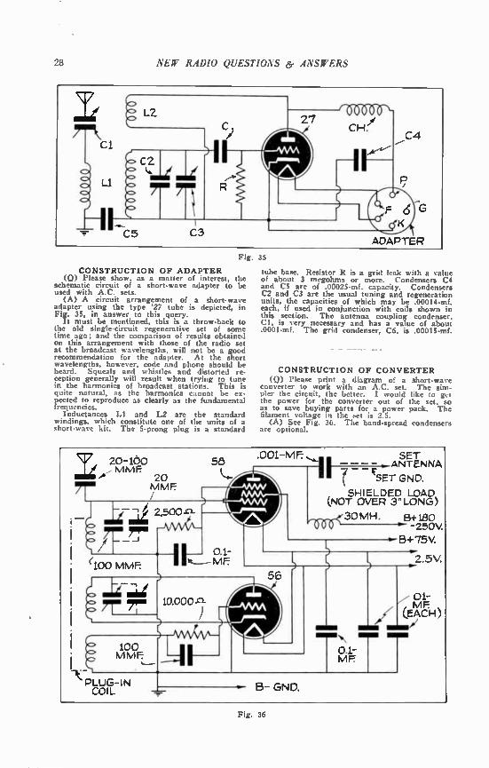
28 NEW RADIO QUESTIONS er ANSWERS
Fig. 35
CONSTRUCTION OF ADAPTER (Q) Please show, as a matter of interest, the
schematic circuit of a short-wave adapter to be used with A.C. sets. (A) A circuit arrangement of a short-wave
adapter using the type '27 tube is depicted, in Fig. 35, in answer to this query.
It must be mentioned, this is a throw-back to the old single-circuit regenerative set of some time ago; and the comparison of results obtained on this arrangement with those of the radio set at the broadcast wavelengths, will not be a good recommendation for the adapter. At the short wavelengths, however, code and phone should be heard. Squeals and whistles and distorted re-ception generally will result when trying to tune in the harmonics of broadcast stations. This is quite natural, as the harmonics cannot be ex-pected to reproduce as clearly as the fundamental frequencies.
Inductances LI and L2 are the standard windings, which constitute one of the units of a short-wave kit. The 5-prong plug is a standard
tube base. Resistor R is a grid leak with a value of about 3 megohms or more. Condensers C4 and C5 are of .00025-mf. capacity. Condensers C2 and C3 are the usual tuning and regeneration units, the capacities of which may be .00014-mi. each, if used in conjunction with coils shown in this section. The antenna coupling condenser. Cl, is very necessary and has a value of about .0001-mf. The grid condenser, C6, is .00015-mf.
CONSTRUCTION OF CONVERTER (Q) Please print a diagram of a short-wave
converter to work with an A.C. set. The sim-pler the circuit, the better. I would like to get the power for the converter out of the set, so as to save buying parts for a power pack. The filament voltage in the set is 2.5.
(A) See Fig. 36. The band-spread condensers are optional.
20-1o0 MME
min& 20
MME
rm re.
PLUG-IN COIL
100 MME
2,500-o-
.001-ME SET 58 111—=-1.-ANTENNÇ. A
%ET GND.
SHIELDED LOAD (NOT OVER 3" LONG)
0.1— mE
no1-30mH.
10.000-ct
56
ammi\
0.1— ME
B GND.
B+180 -250V.
6+75V.
2.5V.
Fig. 36
NEW RADIO QUESTIONS & ANSWERS 29
R.F. CHOKE DESIRABILITY (Q) Ilow is it possible to tell whether a
choke coil is needed in a short-wave receiver? (A) The purpose of a choke coil is to prevent
the passage of alternating current. Its location in a receiver depends upon the design of the re-ceiver. Some sets call for the use of choke coils in dozens of places, while other sets entirely dis-pense with their use. The usual place for at least one choke coil,
in a short-wave receiver, is in the plate circuit of the detector. In one position, it makes re-generation a possibility; without it, no regenera-tion or circuit oscillation is possible. This is prob. ably the use you have in mind. Another action of the choke coil, also in the
plate circuit of the detector, is to prevent R.F. currents getting into the A.F. amplifier. In this position, it will be found in a majority of the better commercial broadcast receivers.
These same receivers, as well as the short-wave receivers, use choke coils in the leads which supply plate potential to R.F. stages, as well as bias potentials for the screen-grid of screen-grid tubes. When used to prevent R.F. currents pass-ing into the current supply units, these choke coils are almost always bypassed with fixed con-densers, as is seen upon inspection of most any schematic circuit; the R.F. is "led" from the "high potential end" of the R.F. choke to a point at low potential. This is ordinarily the ground or the "-B" circuit. When it is desired to use the choke as a "load
impedance" or coupling unit between stages, the fixed condenser connecting to the high potential end of the choke "leads" the R.F. to the stage which follows, instead of to ground.
Erratic regeneration will result if a choke coil is not used in certain circuits. Without choke coils, a tuned R.F. receiver may operate with only one-half the volume it should. Radio frequency choke coils often prevent R.F. circuits from going into uncontrollable oscillation. In screen-grid circuits they are almost a necessity.
If a choke coil is poorly made, "holes" in tuning result; there will be points at which the short-way,- receiver circuit goes out of regenera-tion or oscillation; or, it may go into oscillation with an uncontrollable "thump."
AMATEUR LICENSES (Q) How can I go about getting a license
for an amateur short-wave transmitter? (A) The required forms may be obtained from
the office of the Supervisor of Radio in the Inspection District where you live. The correct
local address may be found in the telephone hooks of the cities shown in parentheses below. Look under U. S. Government, Federal Communications Commission. Be sure to write the supervisor of the correct district, as given herewith:
First District: Maine, New Hampshire, Ver-mont, Massachusetts, Rhode Island and Con-necticut. (Supervisor of Radio, Boston, Mass.) Second District: New York (New York City,
Long Island, and the counties on the Hudson River to and including Schenectady, Albany, and Renssalacr) and New Jersey (counties of Bergen, Passaic, Essex, Union, Middlesex, Mon-mouth, Hudson and Ocean). (Supervisor of Radio, New York, N. Y.) Third District: New Jersey (all counties not
included in Second District), Pennsylvania (coun-ties of Philadelphia, Delaware, all counties south of the Blue Mountains, and Franklin County), Delaware, Maryland, Virginia, and the District of Columbia. (Supervisor of Radio. Baltimore, Md.)
Fourth District: Alabama, Tennessee, North Carolina, South Carolina, Georgia. Florida and the territory of Porto Rico. (Supervisor of Radio. Atlanta, Ga.)
Fifth District: Mississippi, Louisiana, Texas, Arkansas, Oklahoma, and New Mexico. (Super-visor of Radio, New Orleans, La.)
Sixth District: California, Nevada, Utah, Ari-zona and the Territory of Hawaii. (Supervisor of Radio, San Francisco, Calif.)
Seventh District: Oregon, Washington, Idaho, Montana, Wyoming and the Territory of Alaska. (Supervisor of Radio, Seattle, Wash.) Eighth District: New York State (all coun-
ties not included in the Second District), Penn-sylvania (all counties not included in the Third District), West Virginia, Ohio and Lower Pen-insula of Michigan. (Supervisor of Radio, De-troit, Mich.)
Ninth District: Indiana, Illinois, Wisconsin, Michigan (Upper Peninsula). Minnesota, Ken-tucky, Missouri. Kansas, Colorado, Iowa, Ne-braska, North Dakota and South Dakota. (Su-pervisor of Radio, Chicago, Ill.) This subject is thoroughly covered in the
chapter, "Getting Started," in "The Radio Ama-teur's Handbook," obtainable from The Ameri-can Radio Relay League, Hartford, Conn. The prospective "ham" should write to the Govern-ment Printing Office, Washington, D. C., for a copy of "Regulations Governing Radio Com-munication," (10e per copy); and "The Radio Law of 1927," (Sc per copy).
Further procedure is explained on the forms, which are obtainable gratis.
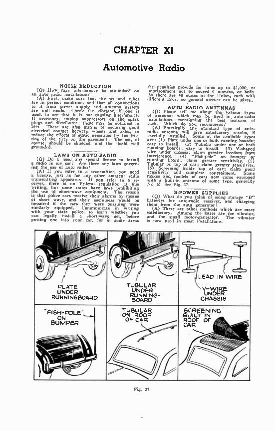
CHAPTER XI
Automotive Radio
NOISE REDUCTION (Q) How may interference be minimised on
an auto radio installation? (A) First, make sure that the set and tubes
are in perfect condition, and that all connections to it from power supply and antenna system are well made. Check the vibrator, if one is used, to see that it is not causing interference. If necessary, employ suppressors on the spark plugs and distributor; these may be obtained in kits. There are also means of securing good electrical contact between wheels and axles, to reduce the effects of static generated by the fric-tion of the tires on the pavement. The set, of course, should be shielded, and the shield well grounded.
LAWS ON AUTO-RADIO (Q) Do I need any special license to install
a radio in my car? Are there any laws govern-ing the use of auto radio?
(A) If you refer to a transmitter, you need a license, just as for any other amateur radio transmitting apparatus. If you refer to a re-ceiver, there is no Federal regulation at this writing, but some states have laws prohibiting the use of short-wave equipment. The reason is that police cars receive their alarms by means of short wave, and their usefulness would be impaired if the cars they were pursuing were similarly equipped. Communicate in writing with your state police, to learn whether you can legally install a short-wave set, before putting one into your car, for in some areas
the penalties provide for fines up to $1,000, or imprisonment not to exceed 6 months, or both. As there are 48 states in the Union, each with different laws, no general answer can be given.
AUTO RADIO ANTENNAS (Q) Please tell me about the various types
of antennas which may be used in auto-radio installations, mentioning the best features of each. Which do you recommend?
(A) Practically any standard type of auto-radio antenna will give satisfactory results, if carefully installed. Some of the available types are: (1) Plate under one or both running boards; easy to install. (2) Tubular under one or both running boards; easy to install. (3) V-shaped wire under chassis; claim greater freedom from interference. (4) "Fish-pole" on bumper or running board; claim greater sensitivity. (5) Tubular on top of car; claim greater sensitivity. (6) Screening inside top of car; claim good sensitivity and complete concealment. Some makes and models of cars now come equipped with a built-in antenna of some type, generally 'co. 6! See Fig. 37.
B-POWER SUPPLIES (Q) What do you think of using storage "II"
batteries for auto-radio receiver, and charging them from the auto generator?
(A) There are other methods which are more satisfactory. Among the latter are the vibrator, and the small motor-generator. The vibrator is now used in most installations.
-
11111e-
TUBULAR
UNDER RUNNING BOARD
1
I
-•.--,--- 9,)
I IM
\..__.___)..)
PLATE UNDER
RUNNINGBOARD
LEAD IN WIRE
V-WIRE UNDER CHASSIS
.. FISH-POLE"
ON BUMPER
,..-------- -
TUBULAR ON ROOF OF CAR
SCREENING BUILT IN ROOF OF CAR
,..„.., 4 -
Fig. 37

w. TRANS 5 R.F C ,
NEW RADIO QUESTIONS & ANSWERS
C.
Ill' CH.
FILTER CONDENSERS
INTERRUPTER ( 6V. BATT.
250V. GENERATOR
31
FILTER SYSTEM
(+250V.
—250V.
Fig. 38
B-POWER VIBRATOR (Q) Please explain how a vibrator is used to
secure B-power for an auto-radio receiver. (A) As you know, the B voltage needed by
radio receivers is far higher than the voltage sup-plied by the usual automobile starting and light-ing battery. You also know that such a battery supplies smooth direct current, and that it is impossible to step up such direct current by means of a transformer. See Fig. 38.
In order to increase the voltage, the battery current is interrupted by a vibrator, and fed into the primary of a transformer. This pulsating direct current acts much like alternating cur-rent, and so induces a current in the transformer secondary. As a step-up transformer is used, the secondary voltage is adequately high for the purpose. It is rectified in the usual way, and
supplied to the plates of the tubes in the receiver. _
REDUCING INTERFERENCE (Q) Can you suggest any way of reducing in-
terference, in addition to the use of spark-plug circuit series resistors? The use of these does not entirely eliminate interference from the motor.
(A) Apparently bypass condensers have not been applied to the several radiating circuits of the ignition wiring in the car. Two bypass condensers, one on each terminal,
at the ammeter may reduce certain forms of car interference. The receiver should not be located near the car's iipition coil, due to its strong field. Interchanging its primary connections may reduce interference. Whether the antenna lead-in shield should be grounded to reduce interfer-ence should he determined uy test.
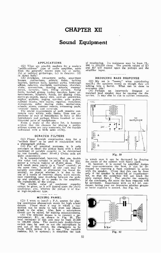
CHAPTER XII
Sound Equipment
APPLICATIONS (Q) What arc possible markets for a modern
"public-address" type of audio amplifier, aside from the generally known ones (a) at parks; (b) at political gatherings; (c) in theatres; (d) in dance halls?
(A) Airplanes, amusement parks, apartment houses, auditoriums, athletic fields, bathing beaches, banquet halls, baseball parks, brokerage offices, cabarets, charitable institutions, churches, clubs, conventions, dancing schools, encamp-ments, factories. fairs, filling stations, flying fields, football games, hockey matches, home en-tertainments, hospitals, hotels, ice skating rinks, merry-go-rounds, motor cars, open-air assemblies, orphan asylums, paging systems, polo games, railroad depots, race tracks, regattas, receptions, restaurants, roller skating rinks, sanitariums, schools, stores, summer resorts, swimming pools, et era ns' homes and carnivals. The sound requirements of such possible cus-
tomers vary within wide limits, from one re-producer or pair of headphones to forty or fifty reproducers and perhaps fifteen hundred or two thousand pairs of headphones. From a study of the above list, it becomes
evident that the chances for placing a public-address system are very numerous, for the capable technician with a little sales ability.
SCRATCH FILTERS (Q) Please furnish construction data for a
"scratch filter" to be used in conjunction with a phonograph pickup.
(A) For all practical purposes, it is only necessary to shunt the pickup leads with a fixed condenser of suitable capacity to be determined by test (usually, about .05-mf.) Choke coils are quite unnecessary.
It is recommended, however, that you double this value and connect in series with the con-denser a variable resistor of 25,000 ohms. This will result more nearly in a "tone" control; at the same time, "scratch" of any type may be suitably controlled, or eliminated (as found de-sirable), no matter whether it is due to the use of a needle of incorrect shape, worn records, poor recording, poor matching between the pick-up and amplifier, or to peaks in the amplifier, the reproducer, or the pickup. The precise value of condenser capacity
cannot be given, as it will depend upon the above conditions; also, whether the pickup is of low-or high-impedance type.
MIXING PANEL (Q) I want to install a P.A. system for play-
ing continuous phonograph music for high school dances. Please show a way in which a con-nection can be made to fade from one phono. graph to the other. Also, how a microphone circuit can be added, for making announcements.
(A) The simplest means is to connect a lee-tentiometer, R1, as shown in Fig. 39. total resistance of this unit may be from 25,000 to 100,000 ohms. The double-pole double-throw switch may be used to cut the microphone in and out of the circuit, the changeover to be made while pickup B is in use. The variable resistor, R2, is optional; it simplifies the task
of monitoring. Its resistance may be from 75,-000 to 250,000 ohms. The precise values of R1 and R2 will depend upon the pickups and the amplifier input.
REDUCING BASS RESPONSE (Q) My set is "boomy" when reproducing
speech; the speakers sound as though they are talking into a barrel. What can be done to overcome this?
(A) Perhaps an incorrectly designed or matched loud speaker may be causing the dis-tortion. It may also be due to cabinet resonance,
Fig. 39
in which case it can be decreased by draping the inside of the cabinet with heavy cloth.
If, however, it is caused by amplifier design that over-accentuates the bass, it can be de-creased by inserting a fixed condenser in series with the speaker. (Note that this can be done only if the speaker is shunt-fed or transformer-fed, so that the condenser will not block the plate current flow.) The smaller the capacity of the condenser, the more the bass response will be decreased. Experiment with an 0.1 mf. con-denser, letting your ear determine whether greater or lesser capacity is needed. See Fig. 40.
Fig. 40
32
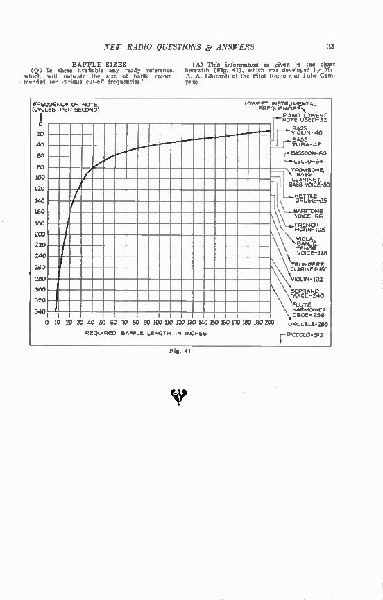
NEW RADIO QUESTIONS & ANSWERS 33
BAFFLE SIZES (A) This information is given in the chart (Q) Is there available any ready reference, herewith (Fig. 41), which was developed by Mr.
which will indirate the size of baffle recom- A. A. Ghirardi of the Pilot Radii, and Tube Corn-- mended for various cut-off frequencies? pans.
FREQUENCY OF NOTE (CYCLES PER SECOND)
0
20
40
60
80
100
120
140
160
180
200
220
24.0
260
280
300
320
340
o
LOWEST INSTRUMENTAL FREQUENCIESN
PIANO. LOWEST NOTE USED-32
BASS VIOLIN-40
BASS I TuBA-42
r-BASSOON-60
-a-CELLO-64
"N. TROMBONE. •., BASS CLARINET BASS VOICE -80
KETTLE \ DRUMS-85
VOICE-96
FRENCH HORN-105
VIOLA. BANJO. TENOR VOICE-128 \TRuMPERT.
CLARINET-1E0
10 20 30 40 50 60 70 80 90 100 110 120 130 140 150 160 170 180 190 200
REQUIRED BAFFLE LENGTH IN INCHES
VIOLIN-192
SOPRANO VOICE-240
FLUTE HARMONICA OBOE-256
UKULELE-28d
r PICCOLO-512 Fig. 41

CHAPTER XIII
Horne Recording
HOME RECORDING RECORDING RADIO PROGRAMS
(Q) What is the way to hook up the least possible amount of apparatus in order to make records of radio broadcasts?
(A) Simply connect a magnetic pick-up to the output of your radio set, by means of a suit-able impedance-matching transformer. Use a turntable with a motor powerful enough to drive the disc when the pick-up has a weight oi about Yi -pound resting on it. Put a home-recording record on the turntable; put a home. recording needle in the pick-up, attach the weight, and proceed to record, with a good, loud signal. If you use an output meter (a low range A.C. voltmeter or ammeter) you can monitor your recording, after a little practice. A single-pole double-throw switch will enable you to shift from radio to recording. The play-back is accomplished through the phonograph connections of the set, a home-recording needle again being used, but the recording weight being removed.
PHONO JACK 5.PD.T
SWITCH
1 TUNED RADIO
FREQUENCY COIL
DETECTOR TUBE
Fig. 42
HOME-STUDIO RECORDING
(0) I wish to make records of my own voice. How can I connect a microphone to my radio set and do this?
(A) See Fig. 42 and the answer to the preceding question for the recording set-up. The microphone, which may be a single-button carbon one, is connected to the primary of a microphone trans-former, the secondary of which connects between grid and cathode of the detector tube (second detector in a super-het.) The regular grid coil is best disconnected while you are recording.
34
CHOOSING A MICROPHONE (0) What sort of microphone is best for home
recording? (A) A crystal microphone or a dynamic mi-
crophone, or a velocity microphone will give the most faithful reproduction. However, these re-quire greater amplification than single- or double-button carbon microphones. In other words, if you do not object to having one or more addi-tional stages of pre-amplification, use one of the first three mentioned; if you want to save stages, though at some sacrifice of quality, use a car-bon mike.
HOME RECORDING RECORDS (Q) What is the best type of record—alum-
inum, celluloid or composition—to use for home recording?
(A) This is largely a matter of taste, and depends to some extent upon the cutting equip-ment used. The writer's personal preference is for composition, when pre-grooved records are used, and for standard 'wax" when blanks are ' used.
(0) Do >ou faun- pre-grooved or blank rec-ords for home recording?
CA) Better recordings can be had by using blanks, but these necessitate the use of some mechanical means of feeding the cutter. For sim-plicity's sake, the pre-grooved records may be used—and they are capable of providing accept-able reproduction, too.
LACK OF VOLUME (1Q) I am using a special celluloid for re-
cording and find it difficult to get the grooves deep enough to give sufficient volume. I have seen "electrical transcription" records, that seem to be made on this same material. How is it possible to overcome this lack of volume?
(A) Your lack of volume is not due to the shallow groove. A shallow groove might make it difficult for the reproducing needle to track, but the lack of volume is due to the modulations (the indentations in the sides of the groove) being too small. This can be caused by several things: perhaps the amplifier's gain is not high enough or there is incorrect impedance matching between cutting head and amplifier; or the mate-rial might be too resistant for good recording; or the cuttting head may be defective or of poor design; or the cutting needle may be dull or incorrectly set. The transcription records are "processed"—that is, a metal stamper is used to impress the sound track. In that case the hardness of the material is reduced considerably, by heating, so that it will take an impression. Try using records of a different material.
- - TONE QUALITY
(Q) I am using my radio receiver for re-cording, and the results are poor. When I re-produce commercial records, the volume is good; but with home-made records the volume is very low. My pickup (when recording) is connected to the plates of the output tubes. Can you tell where my trouble may be?
(A) Evidently your trouble lies in a poor impedance match between the cutter and the am-plifier output. A transformer, to match the cutter and the set's output, should solve the problem.
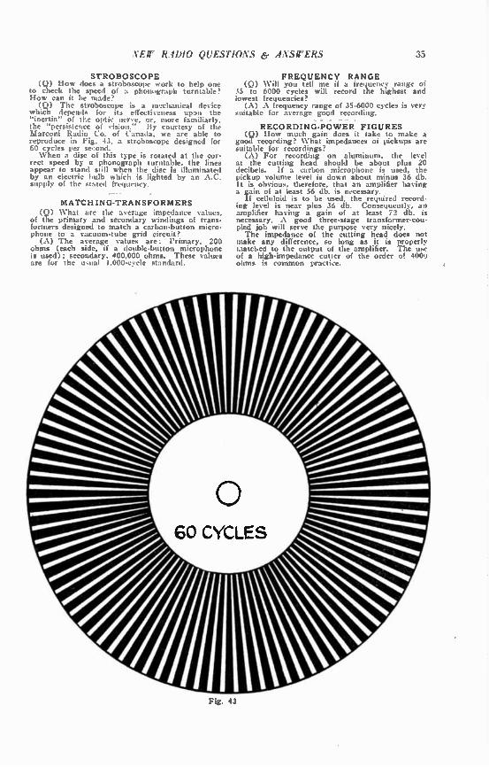
NEW RADIO QUESTIONS (9 ANSWERS 33
STROBOSCOPE (Q) How does a stroboscope uork to help one
to check the speed of a phonograph turntable? How can it be made? (Q) The stroboscope is a m2chanical device
which depends for its effectiseiless upon the "inertia" of the optic nerve, or, more familiarly, the "persistence of vision." By courtesy of the Marconi Radio Co. of Canada, we are able to reproduce in Fig. 43, a stroboscope designed for 60 cycles per second. When a disc of this type is rotated at the cor-
rect speed by a phonograph turntable, the lines appear to stand still when the disc is illuminated by an electric bulb which is lighted by an A.C. supply of the stated frequency.
MATCHING-TRANSFORMERS (Q) What are the average impedance values,
of the primary and secondary windings of trans-formers designed to match a carbon-button micro-phone to a vacuum-tube grid circuit?
(A) The aterage values are: Primary. 200 ohms (each side, if a double-button microphone is used); secondary, 400,000 ohms. These values are for the u,tud 1,000-cycle standard.
FREQUENCY RANGE (Q) Will you tell me ii a frequency range of
35 to 6000 cycles will record the highest and lowest frequencies?
(A) A frequency range of 35-6000 cycles is very suitable for average good recording.
RECORDING-POWER FIGURES (Q) How much gain does it take to make a
good recording? What impedances of pickups are suitable for recordings?
(A) For recording on aluminum, the level at the cutting head should be about plus 20 decibels. If a carbon microphone is used, the pickup volume level is down about minus 36 db. It is obvious, therefore, that an amplifier having a gain of at least 56 db. is necessary.
If celluloid is to be used, the required record-ing level is near plus 36 db. Consequently, an amplifier haying a gain uf at least 72 db. is necessary. A good three-stage transformer-cou-pled job will serve the purpose very nicely. The impedance of the cutting head does not
make any difference, so long as it is properly riatcliect to the output of the amplifier. The use of a high-impedance cutter of the order of 4000 ohms is common practice.
Fig. 43
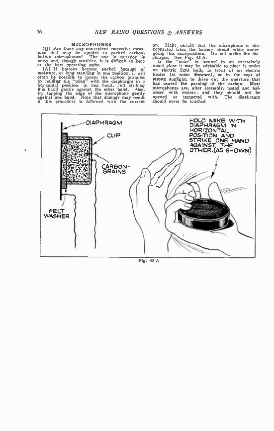
36 NEW RADIO QUESTIONS & ANSWERS
MICROPHONES (Q) Are there any convenient correcti‘e meas-
ures that may be applied to packed carbon-button microphones? The one in question is noisy and, though sensitive, it is difficult to keep at the best operating point.
(A) If buttons become packed because of moisture, or long standing in one position, it will often be possible to loosen the carbon granules by holding the "mike" with the diaphragm in a horizontal position, in one hand, and striking this hand gently against the other hand. Also, try tapping the edge of the microphone gently against one hand. Note that damage may result if this procedure is followed with the current
on. Make certain that the microphone is dis-connected from the battery circuit while under-going this manipulation. Do not strike the dia-phragm. See Fig. 43 A.
Ii the "mise" is located in an excessively moist place it may be advisable to place it under an electric light bulb, in front of an electric heater (at some distance), or in the rays of strong sunlight, to drive out the moisture that has caused the packing of the carbon. Most microphones are, after assembly, tested and bal-anced with meters; and they should not be opened or tampered with. The diaphragm zhould never be touched.
DIAPHRAGM
CUP
CARBON— GRAINS
FELT WASHER
Fig. 43 A
HOLD MIKE WITH DIAPHRAGM IN HORIZONTAL POSITION AND STRIKE ONE HAND AGAINST THE OTHER.(AS SHOWN)
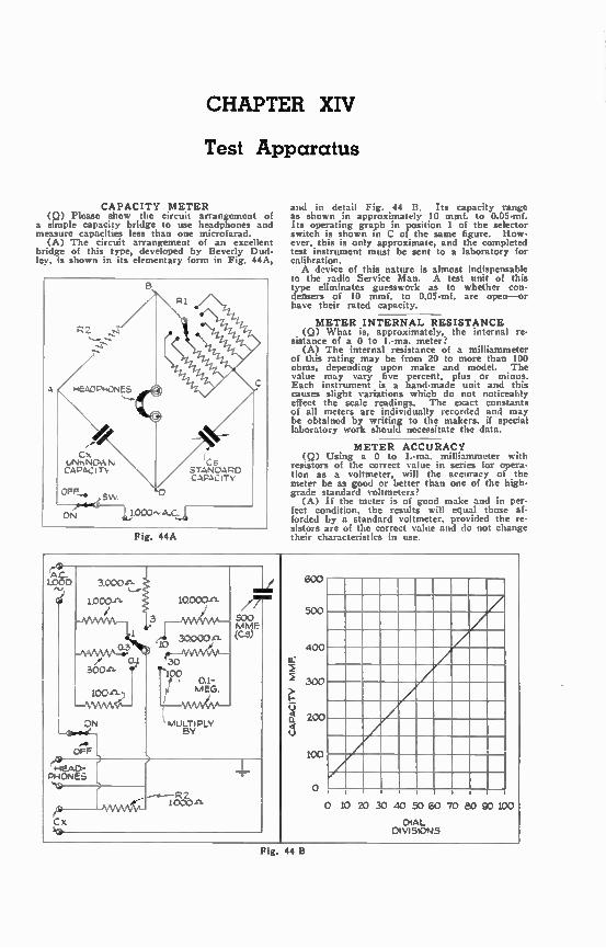
CHAPTER XIV
Test Apparatus
CAPACITY METER (Q) Please show the circuit arrangement of
a simple capacity bridge to use headphones and measure capacities less than one microfarad.
(A) The circuit arrangement of an excellent bridge of this type, developed by Beverly Dud-ley, is shown in its elementary form in Fig. 44A,
Fig. 44A
and in detail Fig. 44 B. Its capacity range as shown in approximately 10 mmf. to 0.05-mf. Its operating graph in position 1 of the selector switch is shown in C of the same figure. How-ever, this is only approximate, and the completed test instrument must be sent to a laboratory for calibration. A device of this nature is almost indispensable
to the radio Service Man. A test unit of this type eliminates guesswork as to whether con-densers of 10 mmf. to 0.05-mf, are open--or have their rated capacity.
METER INTERNAL RESISTANCE (Q) What is, approximately, the internal re-
sistance of a 0 to 1.-ma. meter? (A) The internal resistance of a milliammeter
of this rating may be from 20 to more than 100 ohms, depending upon make and model. The value may vary five percent, plus or minus. Each instrument is a hand-made unit and this causes slight variations which do not noticeably effect the scale readings. The exact constants of all meters are individually recorded and may be obtained by writing to the makers, if special laboratory work should necessitate the data.
METER ACCURACY (Q) Using a 0 to 1.-ma. milliammeter with
resistors of the correct value in series for opera-tion as a voltmeter, will the accuracy of the meter be as good or better than one of the high-grade standard voltmeters?
(A) If the meter is of good make and in per-fect condition, the results will equal those af-forded by a standard voltmeter, provided the re-sistors are of the correct value and do not change their characteristics in use.
AC. 1.000 3.000-n-
1.000-n-
ON
oFF
CEAD-PHONES
10.000-n-
30000-n-
e—AAMAAA-30 100 • 0.1-
/ MEG.
MULTIPLY BY
77-500 MME (Cs)
1000-n-
Cx
CAPACITY MMF.
600
400
200
100
0 10 20 30 40 50 GO 70 80 90 100
DIAL DIVISIONS
Fig. 44 B

38 NEIr RADIO QUESTIONS ey ANSWERS
CIRCUITS OF SET (Q) Please show the various circuits of a
radio set and tell how a Service Man may de-termine what unit is causing bad reception.
(A) The four figures reproduced herewith show the more common connections to triode, tetrode, pentode and other tubes. Ile accom-patiying chart indicates how to analyse the vari-ous indications of faulty operation. Detailed instructions for using these hures follow, through the courtesy of RCA Mfg. Co., Inc.
Illustrated in this treatise are three funda-mental schematic diagrams of the complete fila-ment, plate, grid, and screen-grid circuits for (Fig. 45) filament emitting type tubes; (Fig. 46). cathode-heater type tubes; and (Fig. 47), for out-put pentodes, filament emitting type; and (Fig. 48) for multi-grid tubes. The various circuits are numbered as Example: 1—grid return from grid of tubes to negative C
in grid circuit; 2—plate circuit from positive B on voltage di•
vided to plate of tube; and so forth. Fig. 49 is a chart listing the effects noted (as
compared to the normal readings) when the vari-ous circuits or parts are open or shorted. By the use of this chart, knowing what normal condi-tions are, and how the abnormal conditions com-pare with them, it is possible for a service man to narrow his tracing of the suspected tube cir-cuit, down to the testing of one or two of the parts of that circuit.
Fig. 45
Fig. 47
It will be noted that circuit No. 14 (Fig. 47) applies only to the pentode tubes. It represents the connection within the tube itself from the center of the filament to the suppressor grid, located between the space charge grid and the plate. Since there is no external connection to this element on the base of the tube, the only way in which an open connection between these two elements can be determined is by the ef-fects which this condition would have upon the normal analyzer current and voltage readings. These are listed under circuit No. 14 on the chart, Fig. 49.
Circuits No. 1 and 2 apply equally well to triodes of the filament and cathode-heater types by omitting circuit No. 13 and condenser No. 7 which apply to screen-grid types only. Example: If it is found that the readings at one tube
socket show Eg (grid voltage) equals above normal, Ip (plate current) equals 0, Ekl (cathode voltage on cathode-heater type tubes) equals above normal, then, referring to the chart we see that when this condition exists it indicates a short in No. 6—the plate by-pass condenser —when its return is connected to positive side of grid bias resistor No. 4; or it indicates an open in the cathode circuit through conductor No. 3 or grid bias resistor No. 4. The meanings of the symbols in the reference
chart are as follows:
Fig. 46
Fig. 48
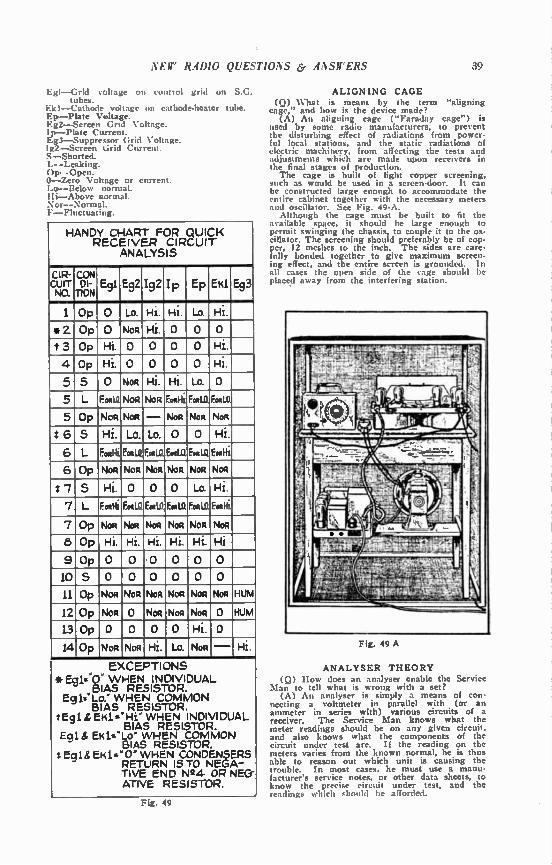
NEW RADIO QUESTIONS & ANSWERS 39
Egl--Grid soilage on control grid on S.G. tubes.
Ek I—Cathode voltage on cathode-heater tube. Ep—Plate Voltage. Eg2—Screen Gnu Voltage. Ip—Plate Current. Eg3—Suppressor Grid Voltage. Ig2—Screen Grid Current. S—Shorted. L--Leaking. Op—Open. 0—Zero Voltage or cum nt. ..o—Below normal. Hi—Above normal. Xor—Normul. F—Fluctuating.
HANDY CHART FOR QUICK RECEIVER CIRCUIT
ANALYSIS
CIR- CUIT NO.
CON' DI-
TION E91 E92 192 Ip Ep EK1 E 3
1 Op 0 Lo. Hi. Hi. Lo. Hi.
*2 Op 0 NOR Hi. 0 0 0
t 3 Op Hi. 0 0 0 0 Hi.
4 Op Hi. 0 0 0 0 Hi.
5 S 0 Non Hi. Hi. Lo. 0
5 L Footle NOR NoR FootHi FoolL0 FoiI.0
5 Op NOR Non — Non Non Non
26 5 Hi. LO. Lo. 0 0 Hi.
6 L Fookli Fong. Fen. Eollia Fog LO. Et*Hi
6 Op Non Non Non NOR Non Non
e/ S Hi. 0 0 0 Lo. Hi.
7 L F. «Hi Foe/ Foe. E01.0. FWD. Fotlii
7 Op NOR Non Non Non NOR Non
8 Op Hi. Hi. Hi. Hi. Hi. Hi
9 Op 0 0.0 0 0 0
105000000
11 Op Non Non Non Non Non NOR HUM
12 Op NOR 0 Non Non Non 0 HUM
L30p0 0 00Hi.0
14 Op Non Non Hi. Lo. Non — Hi.
EXCEPTIONS *Eg1=.0- WHEN INDIVIDUAL
BIAS RESISTOR. Eg 1.'Lo.' WHEN COMMON
BIAS RESISTOR. tEgl &EHI..'Hi" WHEN INDIVIDUAL
BIAS RESISTOR. Eol & EK1.-"Lo" WHEN COMMON
BIAS RESISTOR. 3 Egl& EHl="0" WHEN CONDENSERS
RETURN IS TO NEGA-TIVE END N24 OR NEG-ATIVE RESISTOR.
Fig. 49
ALIGNING CAGE (Q) What is meant by the term "aligning
cage," and how is the device made? (A) An aligning cage ("Faraday cage") is
used by some radio manufacturers, to prevent the disturbing effect of radiations from power-ful local stations, and the static radiations of electric machinery, from affecting the tests and adjustments which are made upon receivers in the final stages of production. The cage is built of light copper screening,
such as would be used in a screen-door. It can be constructed large enough to accommodate the entire cabinet together with the necessary meters and oscillator. See Fig. 49-A.
Although the cage must be built to fit the available space, it should be large enough to permit swinging the chassis, to couple it to the os-cillator. The screening should preferably be of cop-per, 12 meshes to the inch. The sides are care-fully bonded together to give maximum screen-ing effect, and the entire screen is grounded. In all cases the open side of the cage should be placed away from the interfering station.
Fig. 49 A
ANALYSER THEORY (Q) How does an analyser enable the Service
Man to tell what is wrong with a set? (A) An analyser is simply a means of con-
necting a voltmeter in parallel with (or an ammeter in series with) various circuits of a receiver. The Service Man knows what the meter readings should be on any given circuit, and also knows what the components of the circuit under test are. If the reading on the meters varies from the known normal, he is thus able to reason out which unit is causing the trouble. In most cases, he must use a manu-facturer's service notes, or other data sheets, to know the precise circuit under test, and the readings which should be afforded.
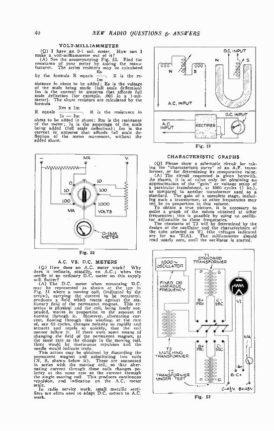
40 NEW RADIO QUESTIONS 6. ANSWERS
VOLT-MILLIAMMETER (Q) I have an 0-1 mil. meter. How can I
make a volt-milliammeter out of it? (A) See the accompanying Fig. 50. Find the
resistance of your meter by asking the manu-facturer. The series resistors may be calculated
Es by the formula R equals —. R is the re-
Im sistance in ohms to be added; Es is the voltage of the scale being made (full scale deflection) Im is the current in amperes that affords full scale deflection (for example, .001 in a 1-mil-meter). The shunt resistors are calculated by the formula
Rm x Im R equals . R is the resistance in
Is — Im ohms to be added in shunt; Em is the resistance of the meter; Is is the amperage of the scale being added (full scale deflection); Im is the current in amperes that affords full scale de-flection of the meter movement, without the added shunt.
Fig. 50
A.C. VS. D.C. METERS (Q) How does an A.C. meter work? Why
does it indicate, steadily, on A.C.; when the needle of an ordinary D.C. meter on this supply will flutter?
(A) The D.C. meter when measuring D.C. may be represented as shown at the top in Fig. 51 where a moving coil, (indicated by the arrow), carrying the current to be measured. produces a field which reacts against the sta-tionary field of the permanent magnet. This re. action is physical and the coil, being freely sus-pended, moves in proportion to the amount of current through it. However, alternating cur-rent, flowing through this winding, at the rate of, say 60 cycles, changes polarity so rapidly and attracts and repels so quickly, that the coil cannot follow it. If there were some means of changing the field of the permanent magnet, at the same rate as the change in the moving coil, there would be continuous repulsion and the needle would indicate truly.
This action may be obtained by discarding the permanent magnet and substituting two coils (N, S, shown below it). These are connected in series with the moving coil, so that alter-nating current through these coils changes po-larity at the same rate as the current through the single moving coil. This produces continuous repulsion, and indication on the A.C. meter scale.
In radio service work, small metallic recti-fiers are often used to adapt D.C. meters to A.C. work.
A C INPUT
D.C. INPUT
AC INPUT RECTIFIER —
Fig. 51
CHARACTERISTIC GRAPHS
(Q) Please show a schematic circuit for tak-ing the "characteristic curve" of an A.F. trans-former, or for determining its comparative value.
(A) The circuit requested is given herewith. As shown, it is of value only for obtaining an approximation of the "gain" or voltage setup of a particular transformer, at 1000 cycles (1 kc.), as compared to another transformer used as a standard. The gain of a complete stage, includ-ing such a transformer, at other frequencies may not be in proportion to this volume. To obtain a true picture, it is necessary to
make a graph of the values obtained at other frequencies; this is possible by using an oscilla-tor adjustable to these frequencies. The constants of T3 will be determined by the
design of the oscillator and the characteristics of the tube selected as VI (the voltages indicated are for an '01A). The milliammeter should read nearly zero, until the oscillator is started.
1.000'Y OSCILLATOR
I L FIXED OR VARIABLE FREQUENCY
L
C:>
TI STANDARD
TRANSFORMER
13 MATCHING
TRANSFORMER
12 TRANSFORMER UNDER TEST
• Y.1
hIA
-A+
B-C4
C:44V. B+45V.
Fig. 52

CHAPTER XV
General Inquiries
STATISTICS (Q) How many radio sets are there in the
United States? In New York City? (A) Late U. S. census figures indicate that
there are approximately 24,500,000 radio sets in operation in the United States; and that nearly five-sixths the population of the country, or a hundred million people, can be classed as "listen-ing public."
It is estimated that in New York, Pennsylvania and Illinois are to be found almost one-third of all the radio sets in the country; and one-fourth New York City is estimated to have about
2,000,000 receivers in use.
SET MODERNIZING (Q) What is the usual procedure in modern-
izing radio receivers? (A) The changes necessary to modernize any
given receiver depend upon the characteristics of the individual set. In general, the wiring and componenta are changed to permit operation with the latest tubes; this may necessitate redesign of the power pack. In some cases the R.F. coils are replaced; a more modern volume control usually becomes necessary; a tone control usu-ally improves the audio quality. Single-dial tuning may replace multi-dial operation; a power detection circuit improves the tone quality, as does the use of a pentode or other high-power output tube. Perhaps the major alteration is the use of A.C. tubes in place of battery-operated types.
HARMONIC PRODUCTION (Q) I have a coil of 85 turns of No. 26 S.C.C.
wire, which is tapped at the 40th turn. I use this in an A.C. oscillator, for balancing purposes, in a unit which covers the broadcast band from 550 to 1500 kc. I now find I am able to use this contraption on the 20-, 40-, and 80-meter amateur bands without the change of coils; thus giving me a range from at least 17300 kc. 17.34 meters, to 560 kc. 535.4 meters. Would you kindly explain this phenomenon;
and could its calibration be relied upon if such is obtained?
(A) It is due to harmonic frequency pro-duction. In an oscillatory circuit including an ordinary vacuum tube, there is produced not only the fundamental frequency of that circuit (due to the values of its inductance and capacity) but al•.o numerous other frequencies which are multiples of the fundamental. These "harmonic" frequencies are rated in their numerical sequence; the fir,,t multiple being the "second harmonic" or double the fundamental frequency; the second mul-tiple is the third harmonic, or three times the fundamental; and so on. The practicability of calibration is evident at
least for the 200- to 1500.1cc. band specified. Further, this method is used in amateur radio transmitting work to calibrate accurately short-wave wavemeters; the signals of crystal-con-trolled stations are used for the fundamental, to which may be tuned (by zero-beat) a vacuum-tube oscillator, whose harmonics may be logged on graph paper for further reference.
If the oscillator is stable, the calibration of the harmonics will be reliable.
41
Constancy and accuracy of calibration are largely a matter of obtaining constant current supply and uniform tube characterictics. In general, quite close work may be done.
BATTERY CARBONS (Q) I would like to use an ordinary battery
carbon as a resistance. What is the average value of one which is six inches long?
(A) These vary from about 50 to 60 ohms.
"NEWTON'S DISC" (Q) I am conducting some experiments in
television and would like to duplicate the physics experiment known as "Newton's Disc." By mounting on a rotable shaft and twirling the card, all the colors of the rainbow painted on it merge into almost a clean white. Can you assist me?
(A) A sketch of the card to which you refer is given herewith, in Fig. 53. We suggest you use the following water colors or oils to get ap-proximately the right effect, which may be close enough for your work.
For red, use vermilion with a little permanent violet; orange, orange cadmium; yellow, chrome yellow; green, blue-green viridian plus a small amount of cobalt blue; blue, prussian blue and cerulean blue; violet, permanent violet and a lit-tle blue; indigo, permanent indigo. Due to optic nerve lag, the colors will, when rotated, re-solve and afford the sensation of white.
Fig. 53
LONG-WAVE RECEIVER (Q) As I would like to make up an experi-
mental circuit to receive long-wave stations for code practice, please print details of this ar-rangement.
(A) The schematic circuit of an easily-built set, a 2-tube "autodyne," is shown in Fig. 41. Although a tuning condenser Cl of .0005-mf.
capacity may be used, it is recommended that

42 NEW RADIO QUESTIONS & ANSWERS
this part have a capacity .of about .001-mf.; which value may be obtained by ganging two .0005-mf. units. The larger capacity will make it easier to tune in a greater number of stations with a lesser number of coils, though the "band. spread" effect will be halved. Any type of 3. element tube may be used at V1 and 112. Honeycomb coils may be purchased, or home-
made coils scramble-wound, with No. 30 enameled S.C.C. wire, on a form an inch wide and about two inches in diameter, to the following num-ber of turns: 25, 80-350 meters; 35, 175-550; 50, 220-750 meters; 75, 330-1030; 100, 450-1460; 150, 660-2200; 200, 1300-4000; 250, 1550-4800; 300, 2050-6300; 500, 3,000-8,500; 600, 4,000-12,000; 750, 5,000-15,000; 1,000, 6,200-19,000; 1,250, 7,000-21,000; 1,500, 8,200-25,000, meters. The two smallest coils are listed merely for
completeness; the ranges are roughly those cov-ered with a .001-mf. condenser. Some form of mounting must be arranged so that the coils may be conveniently interchanged. The coils should be rigidly supported, so that the turns cannot move, even slightly, when the coils are inter-changed.
It may be desirable to insert a resistor of about 1,000 ohms in the detector plate lead at X. Once adjusted for a given coil, tube and plate
potential, resistor R1 need not be reset. The adjustment of R3 is critical. Unit R2 controls solume and sensitivity.
Blocking tube VI prevents radiation of inter-fering frequencies.
— - SIGNAL BOOSTER
(Q) Please show the circuit for an A.C. screen-grid booster unit to be added to the aver-age receiver, for use on broadcast wavelengths.
(A) The circuit requested is Fig. 54; con-nect its "output" to the "Ant." post of the first R. F. tube in the set. The tuning condenser C2 will not "track" closely with the radio set dial unless it is of the same capacity and design of plates; and unless coil L2 has the same effective inductance as the tuned windings in the as-sociated receiver.
Fig. 54
The experimental constants may be as fol-lows: Li, 10 turns of No. 26 D.C.C. wire on a tube 2 inches in diameter; L2, 80 to 85 turns of the same wire on a tube of the same diameter; L13, standard R.F. choke, Cl and C3, 1 mf. fixed condensers; C2, .00035-mf., variable; C4, .00025-mf., fixed; R, 1200 ohms. Resistor R is for biasing the tube.
Over-all shielding, grounded, is shown in dotted lines. The coils should not approach the can more closely than two inches at any point. It is a good idea to connect a 1 ml. condenser as shown in dotted lines.
COLOR CODE (Q) Please explain the system used in color-
coding fixed resistors. (A) Herewith is the color code:
Body or End Dot BLACK - 0 .0 BROWN 1 RED 2 00 ORANGE 3 000 YELLOW 4 0000 BLUE 5 00000 U 6 000000 PURPLE GRAY 8 WHITE 9
The color of the Body ni the resistor sig-nifies the first figure; that of the End, the sec-ond figure; and that of the Dot, the number of zeros which follow the two figures.
Examples are: Resistor with brown Body, black End and black Dot, 10 ohms. Resistor with yellow Body, green End and orange Dot. 45,000 ohms. Resistor with blue Body, no color on end (blue end on blue body obviously can-not be seen) and red Dot, 6600 ohms. Resistor with red Body, brown End and no Dot (red Dot on red Body cannot be seen), 2100 ohms. To remember the order of reading—Body,
End and Dot--think of the initials; they spell BED.
REMOTE SWITCH
(Q) I want to connect up my radio with a switch so that it can be turned on or off from another room. That is, if I turn it on at the set and then e to another room, I want to be able to turn it off from this other room, and if it is off at the set, I want to be able to turn it on from the other room. Or,. if it has been turned on in the other room, I want to be able to turn it off at the set, and vice versa. Switches in series will let me turn it off from both points, but not on if one is open; and switches in parallel will let me turn it on from both points, but not off if both are on. Is there any way in which it can he done?
(A) You will need two single-pole double-throw toggle switches, one at the set, the other at the remote point. Use three-conductor light cord to connect them as shown. Either switch will then turn the set on or off, regardless of the position of the other.
1 •
S.P.ar IN SET (SW. 1)
\ RECEPTACLE FOR SETS PLUG
110V..A.Cr D.C.
REMOTE S. P. D. T. SW. 2
Fig. 55

CHAPTER XVI
Causes of Set Failure
SOURCES OF TROUBLE (Q) Please list various symptoms of trouble
in radio receivers, and state what their causes may be.
(il) The chart herewith, which appeared in Radio-Craft, the magazine for Service Men and experimenters, shows the relation between van out units of the radio receiver and symptoms of trouble which may be caused by defects in them.
WEATHER CONDITIONS (Q) My set does not play as well in damp
weather as in nice weather, and on rainy days it is terrible. Not only is reception noisy, but volume is decreased, and sometimes it whistles. What is the cause of this?
(A) There are a number of possible causes. Dirty or cracked antenna insulators, or an ab-sorbent lead•in strip, or defective insulation of a lead-in wire touching a building can cause weakened and noisy reception on damp days. Coils wound on hygroscopic (moisture-absorbing material, or insulated with a material that is affected by dampness, may cause the same trouble and, by varying their characteristics. may cause the whistles. Other set components, such as sockets and resistors, may have the same effect, if made of hygroscopic material; though this is most unusual.
BAD WEATHER IMPROVES SET (Q) My set does not usually play very well,
but during and right after a rainstorm, it is wonderful. How can I make it play that way all the time?
(A) The most likely reason for this is a poor ground. If your ground connection is in dry soil, it is not good; but when the rain has soaked the earth, the ground becomes excellent. Change the ground. Also possible, but less likely, is that the coils of the set change their character-istics due to dampness, and that the R.F. or I.F. stages are incorrectly aligned when the coils are dry but, through chance, align more nearly right when the weather causes the change. If this is the case, replace the coils. See Fig. 56.
POUR SALT WATER
HERE
METAL ROD
o iL lftF=2. egNe
lee itek;e„'; r1
GROUND LEAD
Fig. 56
43
LINE CORD BURNED-OUT (Q) The line cord of my AC/DC set has
always gotten very hot when the set was play-ing. The other night, it started to smoke, and the set stopped working. What went wrong?
(A) It is normal for line cords to get quite hot, for they contain resistors to reduce the filament current to the proper degree. In your case, the cord was probably damaged or de-fective, and so burned out. There is also the chance that a short in the set (most likely in the filament circuit) caused the cord to be overloaded and thus destroyed it. For that reason, check the set before replacing the cord.
— -- --BURNED ANTENNA COIL
(Q) In moving my 2-volt battery set from one room to the other, I accidentally connected the "A" battery to the Antenna and Ground leads. Of course the set did not work. I soon found the trouble and connected it up right, but still it will not work. I did not burn out the tubes, because they still light, and I had the "B" connections right all the time. Please advise me.
(A) You probably burned out the primary of the first R.F. transformer (antenna coil). Re-place it with a new coil if it appears to be burned, or if it tests open with a flashnight bulb and dry cell, as in Fig. 57.
1.111 ..... nlomo
BATTERY
...... "".
FLASHLIGHT BULB
COIL BEING TESTED
Fig. 57
FUSES BLOW OUT (Q) My set is plugged into the light lines
through a so-called "line noise filter." The fuse in my house circuit blew out the other night. I replaced it and it blew again. This is the circuit that my set is on. It was a 10-amp. fuse, and the fuses in my set are 1-amp. fuses. If there is trouble in my set, why did not the 1-amp. fuses blow before the 10-amp. fuse?
(A) The trouble is probably in the line noise filter, not in the set. Most likely one of the condensers is shorted. Remove the filter and try again. You can test the condensers by connecting them in series with an electric light bulb across the line; if the bulb lights, discard the condenser. There is also the possibility of a short in the set's line-cord or plug; this also may be tested in series with an electric light bulb across the light line. If the bulb lights with the set's switch OFF, the cord or plug should be replaced.
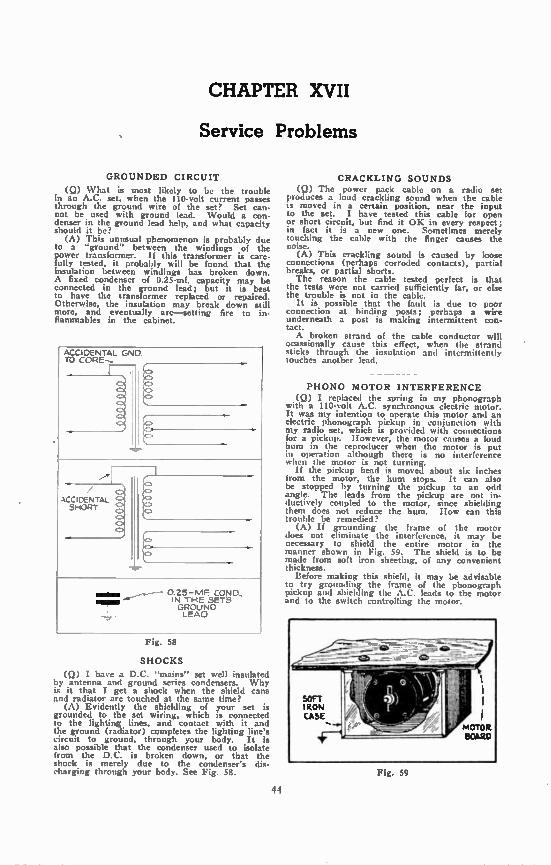
CHAPTER XVII
Service Problems
GROUNDED CIRCUIT
(Q) What is most likely to be the trouble in an A.C. set, when the 110-volt current passes through the ground wire of the set? Set can-not be used with ground lead. Would a con-denser in the ground lead help, and what capacity should it be?
(A) This unusual phenomenon is probably due to a "ground" between the windings of the power transformer. If this transformer is care-fully tested, it probably will be found that the insulation between windings has broken down. A fixed condenser of 0.25-mf. capacity may be connected in the ground lead; but it is best to have the transformer replaced or repaired. Otherwise, the insulation may break down still more, and eventually arc—setting fire to in-flammables in the cabinet.
ACCIDENTAL ONO TO CORE--
0.25-MF COND.. IN THE SETS GROUND LEAD
Fig. 58
SHOCKS
(Q) I have a D.C. "mains" set well insulated by antenna and ground series condensers. Why is it that I get a shock when the shield cans and radiator are touched at the same time?
(A) Evidently the shielding of your set is grounded to the set wiring, which is connected to the lighting lines, and contact with it and the ground (radiator) completes the lighting line's circuit to ground, through your body. It is also possible that the condenser used to isolate from the D.C. is broken down, or that the shock is merely due to the condenser's dis-charging through your body. See Fig. 58.
44
CRACKLING SOUNDS (Q) The power pack cable on a radio set
produces a loud crackling sound when the cable is moved in a certain position, near the input to the set. I have tested this cable for open or short circuit, but find it OK in every respect; in fact it is a new one. Sometimes merely touching the cable with the finger causes the noise.
(A) This crackling sound is caused by loose connections (perhaps corroded contacts), partial breaks, or partial shorts. The reason the cable tested perfect is that
the tests were not carried sufficiently far, or else the trouble is not in the cable.
It is possible that the fault is due to poor connection at binding posts; perhaps a wire underneath a post is making intermittent con-tact. A broken strand of the cable conductor will
ocassionally cause this effect, when the strand sticks through the insulation and intermittently touches another lead.
PHONO MOTOR INTERFERENCE (Q) I replaced the spring in my phonograph
with a 110-volt A.C. synchronous electric motor. It was my intention to operate this motor and an electric phonograph pickup in conjunction with my radio set, which is provided with connections for a pickup. However, the motor causes a loud hum in the reproducer when the motor is put in operation although there is no interference when the motor is not turning.
If the pickup head is moved about six inches from the motor, the hum stops. It can also be stopped by turning the pickup to an odd angle. The leads from the pickup are not in-ductively coupled to the motor, since shielding them does not reduce the hum. How can this trouble be remedied?
(A) If grounding the frame of the motor does not eliminate the interference, it may be necessary to shield the entire motor in the manner shown in Fig. 59. The shield is to be made from soft iron sheeting, of any convenient thickness.
Before making this shield, it may be advisable to try grounding the frame of the phonograph pickup and shielding the A.C. leads to the motor and to the switch controlling the motor.
Fig. 59
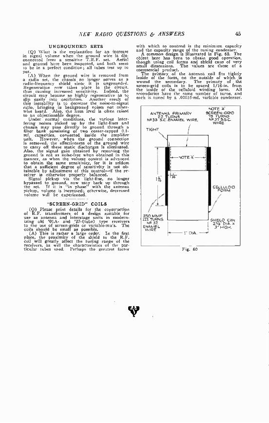
NEW RADIO QUESTIONS êr ANSWERS 45
UNGROUNDED SETS (Q) What is the explanation for an increase
in signal volume when the ground wire is dis-connected from a sensitive T.R.F. set. Aerial and ground have been inspected, and both seem to be in a perfect condition; all tubes test up to
1 A) When the ground wire is removed from a radio set, the chassis no longer serves as a radio-frequency shield since it is ungrounded. Regeneration now takes place in the circuit, thus causing increased sensitivity. Indeed, the circuit may become so highly regenerative as to slip easily into oscillation. Another result of this instability is to decrease the noise-to-signal ratio, bringing in background noises not other-wise heard. Also, the hum fe -el is often raised to an objectionable degree. Under normal conditions, the various inter-
fering noises picked up by the light-lines and chassis may pass directly to ground through a filter bank consisting of two center-tapped 0.1-mf. capacities, connected inside the amplifier unit. However, when the ground connection is removed, the effectiveness of the ground wire to carry off these static discharges is eliminated. Also, the signal gain obtained by removing the ground is not as noise-free when obtained in this manner, as when the volume control is advanced to obtain the same sensitivity, for it is seldom that a sufficient degree of sensitivity is not ob-tainable by adjustment of this control—if the re-ceiver is otherwise properly balanced.
Signal pickup via the light-line, no longer bypassed to ground, now may back up through the set. If it is "in phase" with the antenna pickup, volume is increased; otherwise, decreased volume will be experienced.
"SCREEN-GRID" COILS (Q) Please print details for the construction
of R.F. transformers of a design suitable for use as antenna and interstage units in modern-izing old '01A- and '27-(tube) type receivers to the use of screen-grids or variable-mu's. The coils should be small as possible.
(A) This is rather a large order. In the first place, the proximity of the shield to the R.F. coil will greatly affect the tuning range of the receivers, as will the characteristics of the par-ticular tubes ti.ed. Perhaps the greatest factor
with which to contend is the minimum capacity and the capacity range of the tuning condenser. A common design is illustrated in Fig. 60. The
object here has been to obtain good operation, though using coil forms and shield cans of very small dimensions. The values are those of a commercial product. The primary of the antenna coil fits tightly
inside of the form, on the outside of which is wound the secondary. The primary of the screen-grid coils is to be spaced 1/16-in, from the inside of the celluloid winding form. All secondaries have the same number of turns, and each is tuned by a .00035-mf, variable condenser.
ANTENNA PRIMARY 22 TURNS
Nf2 33 S C ENAMEL WIRE.
TIGHT
350 MMF 121 TURNS N2 32
ENAMEL. VvIRE
Fig. 60
NOTE is: SCREEN-GRIO 75 TURNS N237 S.S.C. WIRE
CELLULOID FORM
SHIELD CAN V/a PIA. X 3- HIGH.
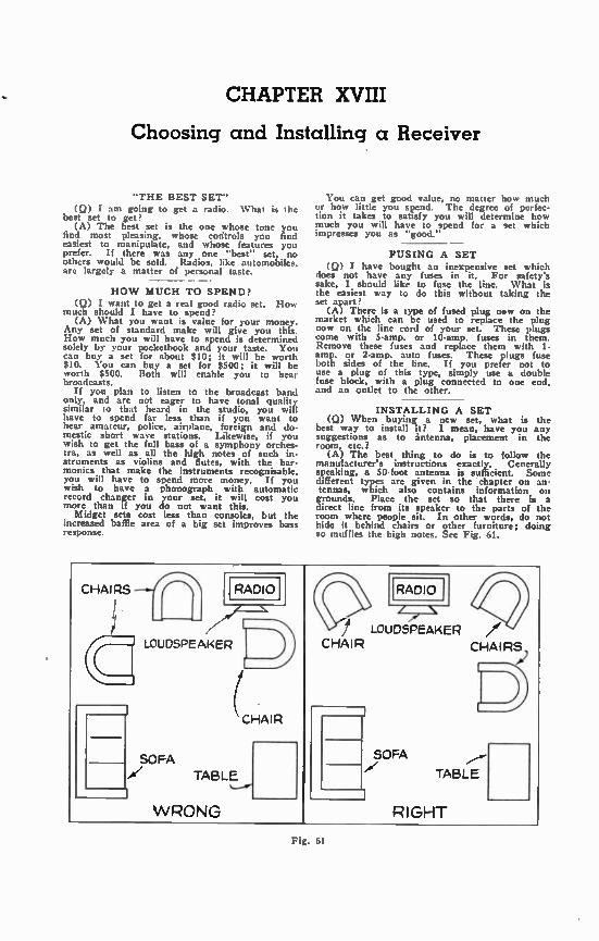
CHAPTER XVIII
Choosing and Installing a Receiver
"THE BEST SET" (Q) I am going to get a radio. What is the
best set to get? (A) The best set is the one whose tone you
find most pleasing, whose controls you find easiest to manipulate, and whose features you prefer. If there was any one "best" set, no others would be sold. Radios, like automobiles, are largely a matter of personal taste.
HOW MUCH TO SPEND? (Q) I want to get a real good radio set. How
much should I have to spend? (A) What you want is value for your money.
Any set of standard make will give you this. How much you will have to spend is determined solely by your pocketbook and your taste. You can buy a set for about $10; it will be worth $10. You can buy a set for $500; it will be worth $500. Both will enable you to hear broadcasts. H you plan to listen to the broadcast band
only, and are not eager to have tonal quality similar to that heard in the studio, you will have to spend far less than if you want to hear amateur, police, airplane, foreign and do-mestic short wave stations. Likewise, if you wish to get the full bass of a symphony orches• tra, as well as all the high notes of such in-struments as violins and flutes, with the har-monics that make the instruments recognisable. you will have to spend more money. If you wish to have a phonograph with automatic record changer in your set, it will cost you more than if you do not want this.
Midget sets cost less than consoles, but the increased baffle area of a big set improves bass response.
You can get good value, no matter how much or how little you spend. The degree of perfec-tion it takes to satisfy you will determine how much you will have to spend for a set which impresses you as "good."
FUSING A SET (Q) I have bought an inexpensive set which
does not have any fuses in it. For safety's sake, I should like to fuse the line. What is the easiest way to do this without taking the set apart?
(A) There is a type of fused plug now on the market which can be used to replace the plug now on the line cord of your set. These plugs come with 5-amp. or 10-amp. fuses in them. Remove these fuses and replace them with l-amp. or 2-amp. auto fuses. These plugs fuse both sides of the line. If you prefer not to use a plug of this type, simply use a double fuse block, with a plug connected to one end, and an outlet to the other.
— — — INSTALLING A SET
(Q) When buying a new set, what is the best way to install it? I mean, have you any suggestions as to àntenna, placement in the room, etc.?
(A) The best thing to do is to follow the manufacturer's instructions exactly. Generally speaking, a 50-foot antenna is sufficient. Some different types are given in the chapter on an-tennas, which also contains information on grounds. Place the set so that there is a direct line from its speaker to the parts of the room where people sit. In other words, do not hide it behind chairs or other furniture; doing so muffles the high notes. See Fig. 61.
CHAIRS RADIO
LOUDSPEAKER
CHAIR
SOFA
TABLEil
WRONG
RADIO
/ N /e
j LOUDSPEAKER /e CHAIR CHAIRS,
SOFA
TABLE
1 RIGHT
Fig. 61
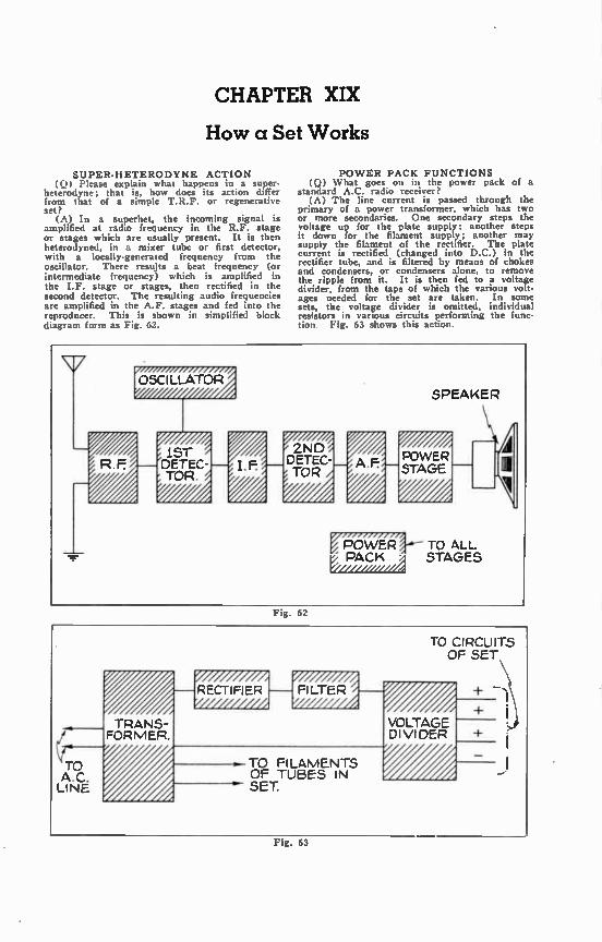
CHAPTER XIX
How a Set Works
SUPER-HETERODYNE ACTION (Q) Please explain what happens in a super-
heterodyne; that is, how does its action differ from that of a simple T.R.F. or regenerative set?
(A) In a superhet, the incoming signal is amplified at radio frequency in the R.F. stage or stages which are usually present. It is then heterodyned, in a mixer tube or first detector, with a locally-generated frequency from the oscillator. There results a beat frequency (or intermediate frequency) which is amplified in the I.F. stage or stages, then rectified in the second detector. The resulting audio frequencies are amplified in the A.F. stages and fed into the reproducer. This is shown in simplified block d'agram form as Fig. 62.
POWER PACK FUNCTIONS (Q) What goes on in the power pack of a
standard A.C. radio receiver? (A) The line current is passed through the
primary of a power transformer, which has two or more secondaries. One secondary steps the voltage up for the plate supply; another steps it down for the filament supply; another may supply the filament of the rectifier. The plate current is rectified (changed into D.C.) in the rectifier tube, and is filtered by means of chokes and condensers, or condensers alone, to remove the ripple from it. It is then fed to a voltage divider, from the taps of which the various volt-ages needed for the set are taken. In some sets, the voltage divider is omitted, individual resistors in various circuits performing the func-tion Fig. 63 shows this action.
Fig. 62
Fig. 63

48 NEW RADIO QUESTIONS & ANSWERS
Fig. ACTION AT TRANSMITTER
(Q) What happens to a sound wave from the time it leaves the singer's lips until it reaches the receiver?
(A) It first strikes the diaphragm of a micro-phone, causing this diaphragm to vibrate. The vibrating diaphragm drives a mechanism which sets up electrical impulses, which are amplified and impressed upon a locally-generated fre-quency (the carrier wave). This is again am-plified and fed into an antenna system, from which it is radiated into space. Part of this wave strikes the antenna system of the receiver and is carried down the Icad•in to the first
64 stage of the receiver. For typical receiver action, see the answer to the preceding ques-tion. Fig. 64 shows a transmitter layout.
PRINCIPLE OF A.V.0 (0) Please tell me upon what principle an
automatic volume control works. (A) The I.F. stages of a superhet are so
connected that their grids are biased by the saine resistor which is used in the cathode-plate cir-cuit of a diode second detector. On a strong signal, there is greater potential drop in the re-sistor, thus altering the bias on the I.F. grids. See Fig. 65 for diagram.
THI OF DETECTOR IN SET.
100 MMF.
MEGA
R2 50,000-n-
-80V.
TO R.F:
SGCRRIDEESN
wiimm 1 MF
Fig. 65
'27
2 ME.
IMF
11
R1 35,000-a
+75V.
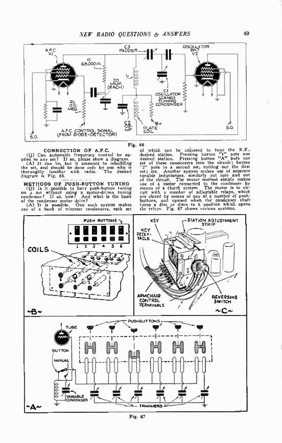
NEW RADIO QUESTIONS & ANSWERS 49
A.FC VI
5 G
68.000.n.
PI 0.5-MEG.
C3 RAMER ir
.1‘ 20 MMF (EACH)
C2 .05-
A.F C. CONTROL SIGNAL MF LFROM DIODE-DETECTOR)
Cl OSCILLATOR
J CONDENSER
134-PLATE COIL
OSCILLATOR 6147 V2
5.G.
Fig. CONNECTION OF A.F.C.
(Q) Can automatic frequency control be ap-plied to any set? If so, please show a diagram.
(A) It can be, but it amounts to rebuilding the set, and should be done only by one who is thoroughly familiar with radio. The desired diagram is Fig. 66.
METHODS OF PUSH-BUTTON TUNING (Q) Is it possible to have push-button tuning
on a set without using a motor-driven tuning condenser? If so, how? And what is the basis of the condenser motor drive?
(A) It is possible. One such system makes use of a bank of trimmer condensers, each set
66 of which can be adjusted to tune the R.F., desired station. Pressing button "1" puts one desired station. Pressing button "A" puts one set of these condensers into the circuit; button "2" puts in a second set, cutting out the first set; etc. Another system makes use of separate tunable inductances, similarly cut into and out of the circuit. The motor method simply makes use of a motor connected to the condenser by means of a clutch system. The motor is in cir-cuit with a number of adjustable relays, which are closed by means of any of a number of push-buttons, and opened when the condenser shaft turns a disc or discs to a position which opens the relays. Fig. 67 shows various systems.
PUSH BUTTONS 't
.11FIll IlL 2 3 4 5 6
KEY STATION ADJUSTMENT STRIP
KEY RECEP-TACLE
ARMCHAIR CONTROL TERMINALS
'
REVERSING SWITCH
TU/SE gir
- --1-
BUTTON
Ç1/4 MANUAL L _.
I
BUT TON
i i I //, í ////, // i i
1 i
••••
"Reg. ier TRIMMERS hs-
--1
Fig. 67

CHAPTER XX
Handy Reference Data
COOVER61011 CHANT for liVEU24672. FRE.UMWCY anci mKULL87101 CceisTANT
A f Lu x f to ,t f tu ...., length
1.1,671, valuss
metio, values
CL c In uf
,... length
16182817 value»
25101717 values
Cr.. ç in ut
Ont. length
Multiply values
Multiply ',duos
CL C In uf
04999 below by 1,030
below by 1,000
L in cm netera below by 1,000
below by 1.000
z in es meters >nob by 1.000
below by 1,210
1 in on
1 2
300000 150000
umpao 942000
0.0003 .0111 .' ,
3.,20 ..
1)00 968
6283 cone
25;33 27.35 1000 000.0 1894 281.6
3 100000 iszeoce oete 3,,,,,20 938 5020 28.83 1050 285.1 1794 310.5
4 75060 471000 .0045 -1.1.,' 909 5/00 30.66 1100 272.7 1712 340.4
5 60000 377000 .0057 .7._ 350
882 857
5540 32.55 1150 260.9
'-76
3/2.1 6 50000 314230 .0101
5„.1.2 833 5383 34.48 1200 250.0
lb 605
7 8
42iico 37500
26s000 235500
.0138
.0180 '''' 811 5230 5090
35.48 38.54
1230 1001
240.0 230.8 1448
440 476
9 33330 209400 „one 3°3 390
701 762
4953 4330
40:7 42.8
1350 1400
222.0 214.4
1396 1346
512 552
10 30000 180430 .0262 1450 206.9 1290 592
15 20000 125600 .0635 410 733 4710 45.0 20 15000 94200 .1129 410 732 4300 4/.3 25 12000 75430 .1755 420 714 4480 49;7 1500 200.0 1256 634 30 35 41
10300 8570 7500
62800 53800 47100
.2530
.3446
.450
430 ,,,, ;;,75
698 682 667
4380 4280 4190
52:0 54.5 57.3
1550 1603 1650
193.5 187.5 1610
1215 11/7 1142
676 720 766
41 6670 41900 .573 460 652 4100 59,6 1700 176.5 1108 813 470 480
638 625
4010 3920
62.3 84.8
1750 1800
1/1.4 168.7
1076 1146
862 912
30 6000 37700 .704 490 612 3642 67.6 1850 162.2 1011 963 55 5450 34220 .852 1930 19/.9 990 1310 70 6010 31420 1.014 f'• 603 3766 70.4
1920 153.8 965 1071 65 75
4623 4290
28970 26900
1.180 1;370 513 586 3692 73.3
75 80 65
4000 3750 3520
25170 23520 212120
1;983 1.801 2,034
520 530 540 560
577 566 556 545
3620 3552 3485 2422
76,0 79:0 82.1 85.2
2300 2350 2103
183.0 146.3 142.9
942 920 898
1126 1123 1241 90
95 3333 3158
20020 19800
2,283 2.541 550
570 536 526
3361 3302
88.4 01.4
2150 2200
139.5 136.4
876 656
1301 1362
580 590
117 501
3246 3193
94.1 92.0
2250 2301
133.3 130.4
038 810
1425 1449
100 3000 18840 2.816 2350 127.1 801 1555 109 110
2857 2727
17940 17130
3.105 3.404 600 500 :140 131.4
24P) 2450
125.0 122.5
784 ,c.8
1622 1690
115 120
2609 2500
16380 15710
3.721 4.05
610 620
492 484
3108 0038
104.1 130;2
125 2400 150/0 4.40 630 470 2990 111.7
130 2308 14480 4.76 640 469 2942 115;4 2500 120.0 753 1762
155 140
2292 2144
13950 13450
5.13 5.92
650 see
462 455
2896 2852
118.8 122.5
2550 2300
117.7 115.4
738 724
1631 1903
145 2069 12990 5.92 610 680
448 441
2610 2766
. 126.3 130.2
2630 2/03.
113.2 111.1
710 697
1077 2052
690 435 2734 134.1 2750 139.1 604 2129 2900 107.1 672 2207
150 2000 12560 6.34 703 429 2692 137.8 2850 105.3 660 2207 169 1935 12150 6.76 710 423 2654 141.9 2030 103.5 648 2366 160 1075 11770 7120 720 417 2816 145.9 2050 101.7 693 2450 165 1618 11413 7.84 730 411 2580 159.0 170 1765 110130 8.13 740 405 2544 154.0 175 1714 10760 8.62 730 400 2510 158.3 180 185
1867 1622
10470 10180
9.12 9.63
760 770
394.8 389.6
2476 2442
162.6 161.8
3303 3500
100.0 85.7
626 528
zees 3448
190 193
1597 1528
9910 9600
10.16 10.71
793 790
ee4.8 279.8
2412 2282
1/1.4 175.6
4)33 9530 5309
75.0 66.7 60.0
4/1 410 377.
4500 5700 7040
5502 54.5 342.2 8520
200 205 210
1500 1468 1429
9420 9190 6970
11.26 11.05 12.41
903 810 820 830
3/5.0 370.4 ,65.0 361.1
2353 2325 2297 2270
190.1 184,7 169.3 194.3
5300 6503 2200 7530
50.0 40.2 42.9 40.0
314.2 269.9 268.8 251.3
13140 11880 13290 15830
216 1395 8760 13.01 840 327.1 2242 220 1364 8530 13.62 651 352.9 2214 It.: 225
200 1333 1304
8370 8190
14.25 14.89
560 349.9 21138 208.2 6000 37.30 235.2 16910 233 1277 8020 15.55
870 344.6 2162 213.2 13503 35.29 221.4 20340 240 1250 7950 16.22
860 340.9 2138 21/.9 0000 33.33 209.2 22900 245 1225 7693 15.90
990 527.1 2115 222.9 0500 31.58 198.2 25410 1)300 15001
52.00 20.00
188.4 125.7
28160 pip,
250 1200 7540 17.63 900 910
553.5 329.7
2092 2070
228.0 233.2
21313 15.00 94.2 112600 255 1177 7390 10.31 920 326.1 2047 230.1 260 1154 7250 10.33 930 322.6 2024 243.4 285 1132 7110 10.77 940 219.1 2003 248.7 25000 12.00 75.4 176010 270 275
1111 1001
69130 20.12 950 315.8 1982 254.1 30030 10.00 62.8 252300 6860 21.20 960 312.5 1962 258.5 35400 8.57 53.8 244800 293 285
1071 1053
674) 22:17 970 309.3 1942 264.7 40000 7.50 47.1 450000 290 1035
6620 22,97 pm 308.1 1922 270.4 45000 6.67 41.8 570000
295 1017 6500 9380
23.68 24.50
ppp 303.0 1902 275.9 33000 6,00 37.7 704000
•
TABLE OF "L-C CONSTANTS" constant, " or the "oscillation constant. " The
This table, reproduced on titis page, shows the calculations follow the Bureau of Standards figure, relationship which exists between wavelength, for the velocity of light, as 299,820,000 meters frequency, inductance and capacity; the latter per second (instead of the older one---300,000,000
two factors are combined under the heading Cl. meters).
- -which is generally referred to as the "L -C
50

.\ Elf it,41)1() QUES7'10.V.S A,VSWERS 51
"TURNS * PER * INCH" of INSULATED WIRE
S. & S. GAUGE DCC SCC DSC SSC ENAM.
ENAM. SCC
and SSC
14 13.7 14.6 14.7 15.0 15.2 14.2 14.7
15 15.0 16.2 16.4 17.0 17.0 15.8 16.5
16 16.7 18.0 18.2 19.0 18.7 17.6 18.4
17 18.5 20.0 20.0 21.2 21.4 19.5 20.5
18 19.6 22.3 22.3 23.6 24.0 21.7 22.9
19 22.5 25.0 25.2 27.0 27.2 24.2 25,8
20 • 24.5 27.5 27.5 29.5 30.1 26.5 28.4
21 27.5 30.8 30.8 32.8 33.6 29.6 31.5
22 30.0 34.0 34.0 36.6 37.7 32.7 35.0
23 32.7 37.5 37.5 40.7 42.3 36.1 39.0
24 35.5 41.5 41.5 45.3 47.2 39.7 43.1
25 38.5 45.7 45.7 50.3 52.9 43.7 47.9
26 41.8 50.2 50.2 55.7 59.0 47.8 52.8
27 45.0 55.0 55.0 61.7 65.8 52.1 58.1
28 48.5 60.0 60.0 68.3 73.9 57.0 64.4
29 52.0 65.5 65.5 75.4 82.2 61.9 70.6
30 55.5 71.3 71.3 83.1 92.3 67.4 77.9
31 60.0 77.3 77.3 91.6 103.0 72.8 85.3
32 62.7 83.7 83.7 101.0 116.0 79.1 93.9
33 66.3 90.3 90.3 110.0 130.0 85.6 103.0
34 70.0 97.0 97.0 120.0 145.0 91.7 112.0
35 73.4 104.0 104.0 131.0 164.0 98.8 123.0
36 77.0 111.0 111.0 143.0 182.0 105.0 133.0
37 80.3 126.0 126.0 155.0 206.0 113.0 146.0
38 83.5 133.0 133.0 168.0 235.0 120.0 157.0
39 89.7 140.0 140.0 181.0 261.0 128.0 172.0
Simply by measuring the length of a coil, you are enabled to calculate the number of turns by using this table.
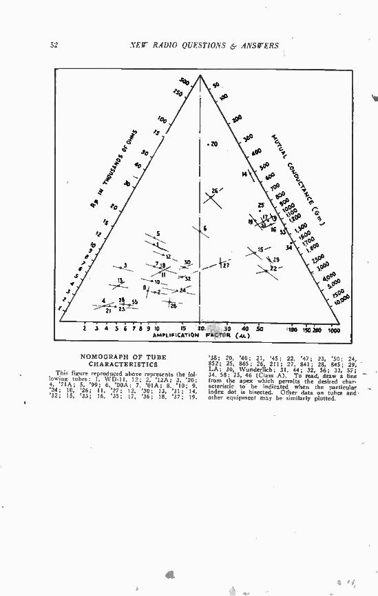
52 NEW RADIO QUESTIONS & ANSWERS
NOMOGRAPH OF TUBE CHARACTERISTICS
This figure reproduced above represents the fol-lowing tubes: 1, WD-11, 12; 2. '12A; 3, '20; 4, '71A; 5, '99; 6, '00A; 7, '01A; 8, '10; 9. '24; 10, '26; 11, '27; 12, '30; 13, '31; 14, '32; 15, '33; 16, '35; 17, '36; 18, '37; 19,
'38; 20, '40; 21, '45; 22, '47; 23, '50; 24, 852; 25, 865; 26, 211; 27, 841; 28, 845; 29, LA; 30, Wunderlich; 31, 44; 32, 56; 33, 57; . 34, 58; 15, 46 (Class A). To read, draw a line - from the apex which permits the desired char-acteristic to be indicated when the particular - index dot is bisected. Other data on tubes and-other equipment may be similarly plotted.

VEW R.4DIO QUESTIONS & ANSWERS 53
CHART OF RADIO SYMBOLS
Nr GROUND ANTENNA INDUCTANCES
BASIC SYMBOL
COIL OF
WIRE
COILS OR CHOKES
AIR IRON CORE CORE
TRANSFORMER
p IRON AIR 1, CORE CORS,
TRANSFORMER
PUSH-S PULL
OUTPUT INPUT
SPEAKERS
I 14 MAGNETIC
faeee r*1 DYNAMIC
PICKUPS
CRYSTAL
MAGNETIC
SWITCHES 4---
--e4."."— MULT7I-TIF:::: S. P. S.T. THROW •----
t_.._
lee lee
D.P.S.T. D.P. D.T GANG e.
0---
0---0
CONNECTIONS
—± NOT CONNECTED
CONDENSERS
TWO PLATES BASIC = OF
SYMBOL IIMM CONDENSER
FIXED VARIABLE BLOCK
mri 7M or& miL4 mLa rim"* -TRIMMERS
Ai-BATTERY -0101-JACKS
OPEN CIRCUIT
CLOSED CIRCUIT
RESISTANCES BASIC jvww._ _ LONG . SYMBOL — ELECTRICAL
PATH FIXED TAPPED
C.T.)
ARIABLE — WFW—
VARIABLE POTEN.
CRYSTAL
/./ PHONES METER
FUSE LINE PLUG
BINDING' POST
TIP-JACK
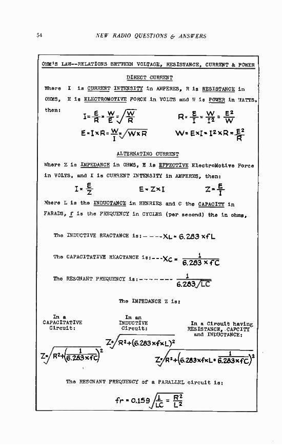
51 NEW RADIO QUESTIONS & .4.\SrERS
OHM'S LAW--RELATIONS BETWEEN VOLTAGE, RESISTANCE, CURRENT & POWER
DIRECT CURRENT
Where I is CURRENT INTENSITY in AMPERES, R is RESISTANCE in
OHMS, E is ELECTROMOTIVE FORCE in VOLTS and W is POWER in WATTS.
then:
=Iff R E R
E-IxR=Vi5F1:7
W _ E2 " I 12 W
W= ExI= I2xR = E2 —PT
ALTERNATING CURRENT
Where Z is IMPEDANCE in OHMS, E is EFFECTIVE ElectroMotive Force
in VOLTS, and I is CURRENT INTENSITY in AMPERES, then:
E I= E- ZxI Z— E
'There L is the INDUCTANCE in HENRIES arid C the CAPACITY in
FARADS, f is the FREQUENCY in CYCLES (per second) the in ohms,
The INDUCTIVE REACTANCE is:— --XL- 6.283 xf L
1 The CAPACITATIVE REACTANCE is:---Xc _ 6.283 x fC
The RESONANT FREQUENCY is. j.
6.283HÍZ
The IMPEDANCE Z is:
In a In an CAPACITATIVE INDUCTIVE In a Circuit having
Circuit: Circuit: RESISTANCE, CAPCITY and INDUCTANCE:
ZIR 2 +(6.283 xfx
ZI-R2+(6.283,cfc) ZJ;12-4-(6.283xfxLx6.283xfC) 1 1 ‘2
The RESONANT FREQUENCY of a PARALLEL circuit is:
pa 2 fr = 0.159 L 1 =
C L2
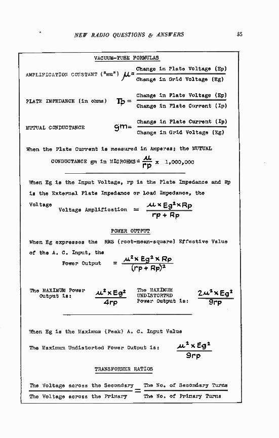
NEW RADIO QUESTIONS 6. ANSWERS 55
VACUUM-TUBE FORMULAS
Change in Plate Voltage (Ep) AMPLIFICATION CONSTANT ("mue)
PLATE IMPEDANCE IMPEDANCE (in ohms)
MUTUAL CONDUCTANCE
Change in Grid Voltage (Eg)
Change in Plate Voltage (Ep)
rP- Change in Plate Current (/p)
Change in Plate Current (Ip)
Change in Grid Voltage (Eg)
When the Plate Current is measured in Amperes; the MUTUAL
CONDUCTANCE gm in MICROHMS= x 1,000,000 rp
When Eg is the Input Voltage, rp is the Plate Impedance and
is the External Plate Impedance or Load Impedance, the
Voltage A.4..X[E9 2 ,cRp Voltage Amplification
rP + Rp
RP
POWER OUTPUT
When Eg expresses the RMS (root-mean-square) Effective Value
of the A. C. Input, the
Power Output
The MAXIMUM Power Output is:
E92
4rp
Eg2 x Rp (rp + Rp)2
The MAXIMUM UNDISTORTED Power Output is:
When Eg is the Maximum (Peak) A. C. Input Value
The Maximum Undistorted Power Output is:
TRANSFORMER RATIOS
2.A.4:1x Eg2
...Li, x Eg2
9rp
The Voltage acroas the Secondary The No. of Secondary Turna
The Voltage across the Primary The No. of Primary Turns

56 NEW RADIO QUESTIONS er ANSWERS
A. C. VOLTAGE and POWER
The MAXIMUM Voltage Em le 1.414 x the EFFECTIVE Voltage E,
The EFFECTIVE Voltage Ee is 0.707 x the MAXIMUM Voltage Em
The AVERAGE Voltage Ea is 0.636 x the MAXIMUM Voltage Em
The POWER in an A. C. Circuit VV= IxEx--i -
Where the ANGLE of LAG or lead, j6 and the Power Factor
COSINE e SINE and TANGENT *
COMBINATIONS of RESISTANCES or CAPACITIES
R _ 7-
The EFFECTIVE SUM of a COMBINATION of RESISTANCES (R) or of a
COMBINATION of CAPACITIES (C) la as follows:
RESISTANCES:
CAPACITIES:
In SERIES
R= R1+R2+R3
C= j j1 CI +E2 4--C
In PARALLEL
1 R - 1 „. 1 4.1
R1 - R2 " R3
C= Cl +C2 +C3
OSCILLATORY CIRCUIT VALUES
Where A (lambda) is the WAVELENGTH in METERS, L is the
INDUCTANCE in MICROHENRIES and C is the CAPACITY ln MICROFARADS
The RESONANT FREQUENCY ln CYCLES le:
(A= 1885,/t(C)
The DECREMENT of a Circuit is (Delta)
Fr= JLXC 159 160
(Se R = 3 1416 x ZfrL • xL
Where the POWER FACTOR is:
CHAPTER XXI
Running a Radio Servicing Business
Q. How may I succeed in opening and run-ning a radio servicing business?
(NOTE:—This question comes from so many Persons, and deals with such an important prob-lem—that of earning a livelihood—that consider-able space must be given to its answer. The fol-lowing data is from "Official Radio Service Hand-book," by J. T. Bernsley, Gernsback Publications, N. Y. C.)
The sincere serviceman assiduously reads through all radio periodicals and technical releases, keenly watching for new equipment, new servicing data and new developments, as well as constantly re-viewing theory on radio and electrical principles. The laggard in the servicing profession, who has only a mercenary interest in his work and who has no inclination to keep informed on develop-ments in his profession, may have been success-ful in fooling his customers and himself in the past. In all probability such servicemen are now confronted by numerous difficulties whenever a modern receiver must be serviced, and exist only through the beneficence of their more skillful brethren to whom they "farm out" the more diffi-cult repair jobs.
There is only one salvation for this type of serviceman and, incidentally, for beginners who may not lack for sincerity but require consider-able additional practical experience and knowledge. This lies in a re-awakening and concentrated ef-fort to master the principles underlying modern receiver design and servicing. Failure to do this will most certainly result in their elimination from the servicing profession, since the struggle to re-pair the ever increasingly complicated receiver will prove too arduous and in most cases unsuccess-ful.
Lest the efficient serviceman be content to rest on his laurels, he too must be warned not to shirk the necessity for continuous improvement in his radio knowledge. The fact that the design of the future receiver promises to become more com-plicated than ever should serve as a warning that any let-down in his studies will result in a handicap which will be most difficult to overcome.
What To Study. The many complex and di-versified circuit arrangements of radio design re-quire that the serviceman have first of all, a thorough grounding in electrical and radio funda-mentals. Principles of magnetism, electricity, fundamental laws of electricity, vacuum tube theory, etc., subjects which every self-sufficient serviceman should have at his finger tips. The beginner in servicing will find the small Radio. Craft Library booklets on a number of radio sub-jects decidedly informative as well as compara-tively inexpensive. Elementary text books dealing with the principles of electricity and radio are published by the following: McGraw Hill Book Co., N. Y. C.; John Wiley and Sons, Inc., N. Y. C., and D. Van Nostrand Co., N. Y. C. Pamphlets or listings of these books may he obtained from ans- of these companies. As an aid to servicemen and radio students, Radio-Craft magazine includes a book review department which describes in out-line the contents of all valuable and newly re-leased radio text book,
57
Many radio manufacturers continually release technical bulletins, pamphlets, service notes and diagrams, booklets and special instruction folders. While some of them are available at no cost to interested parties, those that are charged for are relatively so inexpensive and contain such valu-able information that no serviceman should over-look them. For example, the tube manual pub-lished by the RCA-Radiotron Co. Inc., may be purchased for a maximum of 2k and contains complete characteristic and application data of all radio tubes as well as a wealth of fundamental data on tube operation. This information is of the greatest help to servicemen, especially when servicing receivers for which service diagrams may not be available. The tube manual released by the Sylvania Tube Corp. may be purchased for only 10c, and while not as elaborate as the RCA tube book, nevertheless contains much useful data on special receiving tubes and replacements. The Volume Control Guide available from Electrad, Inc. (N. Y. C.) is also indispensible for service work, since it contains volume control data such as resistance value, type of control, list price, etc. (which guides the serviceman in estimating the price of the repair) for practically all manufac-tured receivers. A very interesting and informa-tive bulletin concerning condensers of all types and their application in industrial and radio fields, as well as receiver design fundamentals, may be obtained monthly for a very nominal sum. This bulletin, known as "The Research Worker", is available from the Aerovox Condenser Corp. Up-to-date information on the theory, design and practical servicing of auto receivers is available in "correspondence course" form from the Radi-art Corp., Cleveland, Ohio. The course consists of a series of booklets, for which there is a nomi-nal charge, and which contain a wealth of valu-able information concerning vibrators, elimination of motor interference, automobile antennas, prac-tical servicing hints, etc. An interesting and ex-tremely valuable, to independent servicemen 'free monthly release is available from the RCA-Vic-tor Co., Inc., Camden, N. J.' its title is "Good News". Besides containing a good deal of help-ful servicing information, numerous suggestions are made for improving the servicing business, and frequently descriptions and suggestions are given of new sales helps and dealer display equipment. Many of these suggestions are excellent, and the displays (available for a small sum from this company) are of real help in stimulating tube sales and servicing business. Many other radio manufacturers release informative bulletins of a similar nature to those mentioned. An announce-ment of their publication and how to obtain them will be found every month in Radio Craft, as they are released.
Personality—Its Importance to the Serviceman. The greatest requirement, next to skill and knowl-edge, is that of proper personality. This is one of the best aids in securing a good position, im-pressing and satisfying a customer and as a re-sult having a successful business. By "proper personality" the author refers to the demeanor or conduct of the serviceman,—the faculty of being a diplomatic conversationalist as well as having that appearance of sincerity and efficiency. Some

58 NEW RADIO QUESTIONS & ANSWERS
servicemen, for example. are loquacious on a serv-ice call, engaging the customer in general conver-sation on every subject from weather to the New Deal while hap-hazardly tinkering with the radio set. Others are overly pompous—stride over to the radio receiver and put on an act of mystery and drama and generally leave the customer either very much befuddled or resentful. Then again we have some servicemen who always either indulge in glib high-pressure salesmanship or else con-tinuously lament over the difficulty of the repair job and the lack of profit, especially when the re-ceiver fails to satisfy and must be reserviced. The really efficient serviceman with proper per-
sonality is the one who quietly goes about his business of servicing the receiver, speaks only when spoken to or else when he has a suggestion to make or is attempting to obtain the case his-tory of the set. He never attempts to "kid" or entertain the customer, and while not reticent is neither verbose. He is especially considerate of the receiver and the surrounding furnishings, and does not spread his tools or servicing equipment all over. When his appraisal of the servicing work necessary is concluded, he specifies his estimate of the repair job to the customer with a satisfactory explanation as to the work involved—without qualms or apology or exaggerated guarantees. Such men are respected and sought after by all who deal with them.
Sales Hints—Improving Business. This subject will naturally interest most the "independent" and dealer-serviceman. Frankly, the author admits that he has some decided views on this subject which may differ from that of other authors and hence may cause some discussion. However, the reasoning is logical and the result of close study. In the first place the "independent" serviceman is only temporarily an independent, until he can either secure a permanent decent-paying position or else accumulate sufficient capital to become a dealer-serviceman. The dealer-serviceman is a combination of business man and service tech-nician, and in addition to having the store at which he conducts his business, he must have a stock of parts and receivers the sale of which provides an income that supplements that derived from servicing. The independent serviceman sells only his serv-
ices that of repairing receivers, carries no stock and seldom has any overhead. He can improve his business only by being as efficient as possible and aggressive—and. this is the cause of most difficulty in this profession—by underbidding his competitor, the dealer-serviceman, on repair charges. In retaliation, the dealer-serviceman probably initiates free tube testing service, 50e inspection calls, and a host of other tricks which lead to intense friction and generally meagre profits, if any, in the income of each.
Consequently, the first step to improve business should be an alliance between the independent and the dealer-serviceman. Prices on repairs should he agreed upon; the independent serviceman should agree to purchase his parts from the dealer-service-man, and allow him a reasonable profit to cover expenses, etc. The dealer-serviceman should, in turn, arrange to carry a convenient stock of re-placement parts and agree to supply the independ-ent with any material that he may need on a cost-plus-reasonable-profit basis. A spirit of co-operation between the two will not only result in improved bysiness to both, but will also earn the respect of all concerned within the community. The dealer-serviceman can further his sales by
prominent and interesting window displays, gen-erally available at little or no cost from most leading radio manufacturers whose lines he might stock. As a rule, the advertising departments of such manufacturers keep their dealer-servicemen continuously informed regarding the type of dis-plays which are available. Failure to receive any display material from manufacturers whose pro-ducts the dealer is carrying should result in an inquiry to the main office. The prestige of the dealer-serviceman will be
greatly enhanced if be should employ modern and complete servicing instruments. His workshop should be neatly arranged and include a complete variety of regular and special servicing tools. Hence, if any customer should walk in and ob-serve the appearance of the shop, the impression made will aid in instilling confidence and respect for his servicing ability. The stock of radio parts, and especially tubes,
should be as complete as possible. The impression left with a prospective customer when some con-ventional item is not in stock is distinctly unpleas-and and may result in the permanent loss of a good customer.
Suggestions On Repair Charges. Suggestions relative to repair charges can only be made in a vague and indefinite sense. The reason for this is that economic conditions in various parts of the country are so different that any recommended specific charge cannot possibly be applicable in all localities. John Jones, serviceman in Pine County, Wisconsin, might live very satisfactorily on an income of $20.00 a week. Albert Smith, service-man in New York City, however, would require a minimum of 35.00 a week to live on the same scale as John Jones in Pine County. Obviously John Jones can afford to charge considerably less for his service than Albert Smith. In addition, the earning capacity of John Jones' neighbors is such as to prohibit a service charge which a New York serviceman might be required to make. Con-sequently, any recommendations made in regards to service charges must take into consideration these important factors.
Unfortunately both John Jones and Albert Smith must pay the same price for their test instruments and tools. Their education and skill in radin servicing is acquired only after the same labori-ous study and experience. Replacement parts cost each about the same, although in some cases the rural serviceman must pay slightly more for a hard-to-get item due to the shipping charges which are incurred when ordering from some radio supply house. The complications and problems of price charg-
ing, as a result of the aforementioned, can only be best overcome by making service charges on the following basis: Service charges should be based on the list price of the material necessary to re-pair the set plus a labor charge based on the time spent in accomplishing the repair. A sug-gestion for rural servicemen is that they make a labor charge at the rate of 75e an hour, and to servicemen in large cities, a labor charge of 1.25 an hour. Of course these suggested charges cannot he
rigidly adhered to if irresponsible servicemen should suddenly start a campaign of price-cutting. Until such irresponsible parties and other detri-mental factors are completely eliminated from this profession, no standardization of price charg-ing can ever be possible.
Potential Fields For Advancement. If the serviceman was only aware of the numerous possi-bilities fdr advancement that exist in this field, then little urging would be necessary to convince him of the advantages of being thoroughly versed and up-to-date in his knowledge of radio prin-ciples and equipment. As a matter of fact, the more skilled and suc-
cessful servicemen are continuously seeking more information and experience in related branches of the radio industry. Many of them are now sufficiently versed in the complexities of theatre sound equipment and public address to be able to efficiently install and service such equipment. Some are furthering their knowledge by studying the design principles of broadcast transmitter equip-ment, whereas others are more interested in sound recording apparatus and methods. Obviously the motivating factor behind this interest is a keen desire to branch out into some allied but more remunerative field. In addition, the knowledge, experience and employment in these related indus-tries legitimately entitles the serviceman to the

NEW RADIO QUESTIONS & ANSWERS 59
more dignified appellation of "engineer." And few are the sincere servicemen who do not aspire and make every effort towards attaining this goal!
Hence, not only has the skilled and thoroughly versed service technician that greater advantage of being able to service all receivers more effi-ciently, but as a rule, such men are more success-ful in obtaining advanced radio positions with leading radio manufacturers. These positions per-tain to field service, theatre sound equipment in-stallation and service, lecturing engineer to other servicemen, police radio installation and service, aviation radio installation and service, etc., etc. It is self-evident that the mediocre or haphazard hit-or-miss type of serviceman can never hope for or aspire to such positions, unless of course, lie should apply himself diligently to increasing his radio knowledge and skill.
Uplifting The Profession Since this book is intended chiefly for service-
men or those contemplating entering the servicing field.—a frank and open discussion of the evils which exist in this profession is entirely in order. It will be agreed by all who have been in it for some time that conditions are far from being satis-factory, and that few are making a decent liveli-hood from radio service work at the present time. The constant necessity for new test instruments to facilitate the servicing of receivers that in-corporated tremendous changes in design from year to year, the necessity for laborious and in-tensive study of the changes made and theory in-volved, and the constant expense for periodicals and books which furnish the information are all factors which serve as a millstone around the serviceman's neck. The aforementioned expenses and effort would
be gladly tolerated as a necessary evil, if it weren't for the fact that servicemen in general are so poorly paid. This is true regardless of the classi-fication of servicemen, whether independent, dealer-serviceman, or the employed technician. The average salary of men who are employed in this profession in big cities seems to be approximately 30.00 per week. What the independent or dealer. serviceman earns may vary from a mere pittance to as high as $70.00 per week, but the latter figure is not only unusual but is attained only in season and by aggressive and expensive adver-tising, as well as long hours and hard work. In addition, the prestige of the serviceman is rather low, since he is regarded with contempt by others in the radio industry and, as a rule, d?strusted by the average customer.
Cause of Evils in Servicing. What are the reasons for such conditions in this profession? How may they be overcome? What other profession, excepting the medical, requires that its men have such a thorough and diversified knowledge and skill, and such a variety of expensive instruments and tools to enable them to perform their work? The answers to these questions can only be ob-tained through close analysis and study of all the factors which are associated with the pro-fession.
First of all, how does a man enter the servic-ing profession? How and where does he serve his apprenticeship and when does he become a full-fledged serviceman? Most would-be service-men start as constructors or experimenters, and acquire their knowledge through practical experi-ence in building sets and experimenting with cir-cuits and by constant study of circuit design and radio and electrical theory. Others are graduates of radio schools and by intensive study can ac-quire, through this means, quite a bit of radio knowledge. Naturally, these men are anxious to perform service work at any opportunity, despite the fact that their practical training is still in-sufficient for thorough and efficient work. Each re-pair job presents a possibility of making some extra money, therefore why not do such work? There are no restrictions, no obstacle placed in their path, especially since replacement parts are available to anyone at wholesale prices from prac-
tically any radio mail order house. What does it matter that the repair joli may not turn out com-pletely satisfactory and that the stigma of in-efficiency may be placed on the profession as a whole? Of course there is always the possibility of the repair being some simple and easy thing to effect, but then this author has seen some samples of simple radio jobs that were performed by auto mechanics or radio salesmen that should never be allowed any closer to a receiver chassis than the tuning controls. The unfortunate thing about this situation is
that there are quite a great many of such pseudo-servicemen. They glut the market by competing in repair quotations, vieing with regular service-men for positions, and by indulging in all sorts of unethical and nefarious practices which are injurious to both the business and the good name of the profession. To eliminate them entirely is practically impossible, and in some cases impractical since many of these men can be reclaimed and may eventually turn out to be outstanding men in the profession. But their activity in servicing is causing many hardships among legitimate and skilled members of the profession. Hence, to minimize most of the evils in servicing, the author direct's the reader's attention to the following plan.
Proper Organizing—the Means of Overcoming Servicing Evils. The call to organize has un-doubtedly been repeatedly heard by all active serv-icemen. While it has found favor with the ma-jority there are nevertheless a considerable number who are reluctant to join, since previous service associations have consistently failed to accomplish anything towards remedying existing evils. The trouble, in most cases, has been that most organiza-tions were either formulated without any specific plans, or else were gotten up by selfish parties in-terested only in exploiting the serviceman. The latter type of organization solicits membership applications from any interested parties willing to pay dues. It also obtains quite an income from manufacturers willing to have their equipment constantly brought to the attention of servicemen members. Even most so cálled "lectures", which these organizations supposedly give to educate the serviceman, are nothing but masqueraded pub-licity talks. A sincere and bona-fide service organization can
accomplish much towards "cleaning-up" in the profession. By mass pressure radio mail order houses can be made to sell radio parts and equip-ment at wheesale to legitimate servicemen only. What manufacturer or mail order house can afford to defy an organization of thousands of men? And, of course, men not deserving of the title of "servicemen" can then be ostracised from the profession by refusing them membership in the organization. Without a membership card they will not he able (if the organization is success-ful) to obtain replacement parts at wholesale prices, and hence cannot offer competition to legiti-mate servicemen. Apprentice servicemen (those not thoroughly experienced) should be given a mem-bership card which will allow them to he em-ployed as apprentices at a reduced wage scale. Until they attain the efficiency and knowledge of the skilled technician they should not be entitled to purchase material at wholesale prices. This would tend to discourage their activity as inde-pendent servicemen and will keep them confined to servicing sets under the supervision of their more skilled brethren.
The Proper Organization to Join. Obviously, for any such organization to be entirely success-ful it must be directed by sincere and honest men who are really interested in the welfare of the profession. It should preferably be national in scope, although consisting of a number of "chapters" or "locals", since the larger the or-ganization and the greater the number of mem-bers, the more successful will be its endeavors to accomplish reforms. What should prove of great interest, and serve
as a model to servicemen in all parts of the coun-
60 NEW RADIO QUESTIONS & ANSWERS
try, is the recent success of the Radio Tech-nicians' League of New York City in becoming affiliated with the American Federation of Labor. By obtaining a charter under the International Brotherhood of Electrical Workers with separate autonomy and other privileges, it has made tre-mendous strides in membership and the elimination of many local professional problems. There can be no question as to the improvement in the morale of its members. While they once waged a lone and almost futile fight for reforms, they now have the support and backing of all affiliated A. F. of L. unions. In addition, they now have the right to or-ganize all metropolitan servicemen under a charter which recognizes them as a union of craftsmen to be governed by themselves.
Their platform consists of combating the policy of mail order houses to sell at wholesale to any Tom, Dick or Harry. They are making every effort to attain increased wages and lower work-ing hours. Technical lectures and instruction talks are held twice a month. Each applicant for mem-bership is given an examination and then graded as either a technician or apprentice. Examinations for grading are held each year, so that to main-tain their status all technicians are forced to study and keep abreast with developments. The apprentice becomes a technician if he can pass the technician's examination. There are, of course, many other features which are typical of union organization such as free medical service, insur-ance, technical aid and advice, etc.
While the author does not meant to imply that success in organization can only be accomplished by affiliation with the American Federation of Labor, there are numerous features or advan• tages that will result from such an affiliation that will help tremendously in reaching the desired goal of the profession. The formation of indi• vidual groups or associations with their petty differences has been tried time and again, and the lack of cooperation and disinterest in the com-mon problems has always resulted in complete failure to accomplish anything for the profession. On the other hand, an organization of national
scope, with all its chapters or locals strongly tied together, and bound to cooperate and work for the common good of all servicemen, must obtain some measure of success since the strength of such a union cannot fail to impress and affect the pub-lic, the employer and all other related parties.
How to Organize. It is a comparatively simple matter for a group of servicemen to get together and form an association. However, to do any real good for the profession as a whole, the author strongly advises against the formation of indi-vidual and disjointed groups which may pull against each other and thus cause more harm than any common good. It is for this reason that the author is a strong proponent of unionism, since each local or chapter is tied to a parent organization, the officials of which are elected by representatives from each local, and who must strive to do their best for the profession as a whole. There are a number of other features the mention of which should be unnecessary since practically everyone is familiar with the prestige of union labor organizations. The success of teamsters, laundry-wagon drivers,
chauffeurs, electrical workers, machinists, etc., etc., in acquiring decent working hours and substantial increases in salaries due to union organization, serve as splendid examples of this point. In con-trast with the radio servicemen, these men re-
quire no intensive training or study, no elaborate and expensive equipment and yet make consider-ably more (with less effort and hours) than the majority of skilled technicians. It is the author's belief that if union organization can do this for the aforementioned trades, then it certainly should be able to accomplish as much for the servicemen of this nation. And, if affiliation with the A. F. of L. will give the serviceman the "break" he is looking for in getting decent working hours and wages, then by all means servicemen should af-filiate with the A. F. of L. On one thing we can all agree, present condi-
tions are far from satisfactory to the majority of men in this profession. Something must and shall be done about it, and that something has its solution in organization of all men who are doing service work. Let us not have disjointed and individual clubs or associations working against each other! We must cease being the football for privately owned and sponsored organizations that are operated for selfish reasons and not for the good of the profession. This applies es-pecially to associations that exact "dues" from its members and give them nothing in return but manufacturer's lectures designed to stimulate the merchandising of the manufacturer's products. Usually that type of association never even pays for the costs of the lecturers, and accomplishes this by working in agreement with the manufac-turer who pays for all expenses in return for the publicity and credit that the association gets.
Let us have an organization for the service-man, run by servicemen, and working in the interests of all servicemen. Avoid joining or affiliating with any club or association just for the sake of obtaining a few bulletins sr releases that seldom, if ever, facilitate your work or aid you in your economic problems. Such an affiliation only serves to give that organization undeserving prestige, and helps to minimize the efforts and accomplishments of sincere servicemen associations. Investigate first whether the organization you con-template joining is doing any real good for the profession. Determine whether the "euh" has any interest in some particular radio manufac-turer, and whether it runs sponsored lectures paid for by the manufacturer. Ascertain what its plans are in regards to the servicemen of the country, and look up its record for accomplish-ments in its period of existence. These points are all very important, if members of this profession are to be assured of the organization's sincerity to overcome the many evils that are responsible for the unwarranted and unsatisfactory conditions that exist in servicing today.
Best of all, if there is no sincere and active organized group of servicemen in your locality now, form such an organization as soon as pos-sible. Hold technical or social and economic dis-cussions and keep organized until an opportunity presents itself when you can affiliate with a larger and more active but thoroughly sincere organiza-tion that is national in scope. If present organ-izations are not sufficiently satisfactory to affiliate with, then such a national organization must ap-pear soon. All it requires is the will and the spirit of the servicemen to create its existence.
This author will be pleased to hear from service-men for comments, suggestions or desiring further advice concerning organization. It is conceded that the suggestions outlined may not be in accord with the beliefs or plans of all concerned in the servicing fraternity.
c+)

CHAPTER XXII
Conclusion
These, then, are the questions which seem to bother many radio fans and experimenters. But, of course, there are innumerable other queries which may rise to plague the radio enthusiast. The most valuable knowledge which can be
imparted to him is that which enables him to find the answers to his questions through in-dependent investigation. The procedure is simple: it consists merely in
knowing whom to ask. For problems involving the installation, opera-
tion or repair of factory-built apparatus, the best source of information is the service depart-ment of the manufacturer. In seeking infor-mation, ?ive all the available data about the receiver in question, being sure to include the make and model number (usually to be found on a plate attached to the cabinet or chassis).
For problems involving the use of parts, the correct source is the manufacturer of the part. He is anxious that it perform to your satisfac-
Type
Tube
2A3 2A5 2A6 2A7 2B7 2B7 2B7 6A7 6A7 6A7 6B7 6B7 6B7 6F7 6F7 6F7 24A 24A 24A 24A 26 26 27 27 27 35 35 36 36 36 36 36 37 37
tion, and his service department will help you in every possible way.
Information relative to amateur requirements, broadcasting regulations, etc., may be obtained from the Federal Communications Commission, in Washington, D. C., or from the U. S. Super-visor of Radio in your district. Data on schedules of short-wave or broadcast
stations is best secured from the stations them-selves. Information as to general station list-ings can be had from any of the call books sold on newsstands.
Technical information can be had by referr-ing to standard text books and technical maga-zines. This includes circuits for sets which the inquirer wishes to construct.
All other queries (and there are not many which do not fall into the foregoing categories) can be had from the questions and answers de-partments of various technical radio magazines.
BY-PASS CONDENSER, GRID-BIAS RESISTOR CHART
Purpose
A A A
A(rf) A(rf) A(af) A A
A(rf) A(rf) A(af) A • A Mixer A(rf) A(rf) A(af) Det A A A A Det A(rf) A(rf) A(rf) A(rf) A(rf) Det Det A A
Plate Screen
Volts Volts
250 - 250 250 250 250 100 100 100 250 100 250 50 100 100 180 180 250 100 100 100 250 125 250 50 100 250 100 250 100 190 90 250 90 500 75 275 30 90 180 135 250 250 180 90 250 90 100 55 180 90 250 90 100 55 250 90 180
90
61
Grid Grid Resistor By-pass Cap.
Volts in OHMS in Mfds.
-45 -16.5
-3 -3 -3 -4.5 -6.5 -12 -3 -3 -3 -4.5 -3 -3 -10 -3 -3 -4.5 -5 -7 -14.5 -9 -21 -30 -3 -3 -1.5 -3 -3 --5 -8 -6
750 400
2500 500 400 250
7000 600 500 500
4000 2500 7000 500 400
2500 500 500
3000 50000 2500 1. 2250 2000 4000 50000 1.
350 350 800 1000 600
50000 80000 2500
-13.5 3000 1.
20. 25. 2. .1 .1 .1
1. )5. )5.
.1 1 1
I.
.1
.1
.1
.1 I. 1.
1. 1.
.1
.1
.1
.1
.3
.5 1.
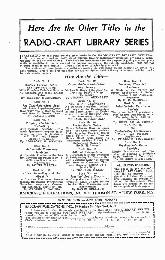
Here Are the Other Titles in the
RADIO-CRAFT LIBRARY SERIES
PRESENTED on this page arc the other books in the RADIO-CRAFT LIBRARY SERIES— the most complete and authentic set of volumes treating individually important divisions of radio,
refrigeration and air conditioning. Each book has been written for the purpose of giving you the oppor-tunity to specialize in one or more of the popular branches of the subjects mentioned. The material in these books is very helpful . . . you'll find them valuable in your work.
The authors of these books are well-known—they are authorities on the subjects on which they have written. This is the first time that you are enabled to build a library of uniform technical books by such popular writers.
Book No. 2
Modern Vacuum Tubes And How They Work
With Complete Technical Data on All Standard and Many Special
Tubes By ROBERT HERTZBERG
Ronk No, 3
The Superheterodyne Book All About Superheterodynes
How They Work. Now to Build and I-low To Service Them
By CLYDE FITCH
Book No. 6 Bringing Electric Sels
Up-To-Date With Pentodes. Mutli-Mus, Dy-namic Speakers—Complete Infor-mation on How to Modernize
A.C.. D.C.. and Battery-Operated Receivers
By CLIFFORD E. DENTON
Book No. 9
Automobile Radio and Servicing
A Complete Treatise on the Sub-ject Covering All Phases from In-
stalling to Servicing and Maintenance
By LOUIS MARTIN
Ronk No. 10
Home Recording and All About It
A Complete Treatise on Instan-taneous Recordings, Microphones, Recorders, Amplifiers, Commer-cial Machines. Servicing, etc. By GEORGE J. SALIBA
RADCRAFT PUBLICATIONS, INC. • 99 HUDSON ST. • NEW YORK, N.Y.
Here Are the Titles— Book No. 12
Public Address Installation and Service
Modern Methods of Servicing and Installing Public Address
Equipment By JOSEPH T. BERNSLEY
Book No. 13 ABC of Air Conditioning
An Accurate Simplified, Techni-cal Review of the Fundamentals of this Latest Branch of Engin-eering, Including Servicing Data
on Present-day Units By PAUL D. HARRIGAN
Book No. 14 Pocket Radio Guide
Handy Reference Book for Radio Men— Set Construction Articles Audio Amplifier Circuits—Useful Radio Formulas and Data — Handy Short Cuts—Index to Important Articles Printed in
Radio-Craft Magaz'ne By N. H. Lessen
Book No. 15 ABC of Ref rigezation
A Compendium of the Principles of Refrigerating for Service Men with a detailed Listing of Defects and How to Overcome Them,
with Hints on Setting Up a Service Shop
By TRAFTON MASON
Book No. 16 Practical Radio Circuits
A Comprehensive Guide to All Types of Radio Circuits for the Service Man, Constructor and
Experimenter By DAVID BELLARE
Book No. 17 Servicing With Set
Analyzers A Study of the Theory and Proper Applications of Modern Set Analyzers and Associated
Aooaratus By H. G. McENTEE
Book No. IR Point-To-Point Resistance
Analysis Theory — And Application of This Modern Test Procedure in
Every-day Radio Service Problems
By BERTRAM M. FREED
Book No. 20 Tim
Cathode-Ray Oscilloscope Theory and Practical
Applications By CHARLES SICURANZA
Book No. 21 Breaking Into Radio
Servicing Simpla Instructions and Pro-cedure for Starting a Profitable Radio Business of Your Own By ROBERT EICHBERG
ALL BOOKS UNIFORM The books in the RADIO-CRAFT LIBRARY SER-IES are all uniform . . . size 6 x 9 inches. Each vol-ume contains an average of 50 to 150 illustrations. The books are printed on an ex-cellent grade of book paper.
CLIP COUPON — AND MAIL TODAY!
RADCRAFT PUBLICATIONS, INC., 99 Hudson St., New York, N. Y. I have circled below the numbers of hooks in the RADIO-CRAFT LIBRARY SERIES,
which you are to send me POSTAGE PREPAID. My remittance of is en-closed at the cost of fifty cents for each book. The amount of my remittance is (Stamps. checks or money orders accepted.) Circle numbers wattt,',l 2 3 t, 9 111 12 13 14 15 1, 17 1>t
Address
State QA Send remittance by check, stamps or money order; register letter if you send cash or stamps.
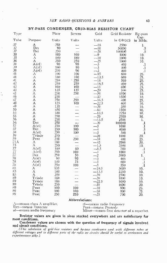
VEIr RADIO QUESTIONS & ANSWERS 63
BY-PASS CONDENSER, GRID-BIAS RESISTOR CHART
Type Plate Screen Grid Grid Resistor By-pass Cap.
Tube Purpose Volts Volts Volts in OHMS in Mfds.
37 A 250 - -18 2500 1..5 37 Det 90 - -10 50000 37 Det 250 - _../8 140000 .5 38 A 100 100 -9 1000 10. 38 A 180 180 -18 1000 10. 38 A 250 250 -25 1000 10. 39 A(rf) 90 90 -3 400 .1 39 A(rf) 180 90 -3 400 .1 39 A(rf) 250 90 -3 400 .1 41 A 100 100 -15 600 25. 41 A 180 180 -13.5 600 25. 41 A 250 • 250 -18 500 25. 4" A 250 250 -16.5 400 25. 43 A 100 100 -15 600 25. 43 A 135 135 -20 500 25. 45 A 250 250 -50 1500 10. 46 A 250 - -33 1500 10. 47 A 250 250 -16.5 400 25. 48 A 195 100 -22.5 400 10. 49 A 135 - -20 350 10. 50 A 450 - -84 1500 10. 55 A 180 - -13.5 2250 10. 55 A 250 - -90 2500 10. 56 A 250 - -13.5 2500 1. 56 Det 250 - - 90 100000 .1 57 A(rf) 950 100 -3 1000 .1 57 Det 250 100 -4 4000 .5 58 A(rf) 250 100 -3 300 .1 59 Triode 250 - -28 1000 20. 59 Pent 250 250 -18 400 25. 71A A 180 - -43 2000 20. 75 A 250 - -1.5 3500 10. 77 A(rf) 100 60 -1.5 700 .1 77 A(rf) 250 100 -3 1000 .1 77 Det 250 50 -2 3000 1. 78 A(rf) 90 90 -3 400 .1 78 A(rf) 180 75 -3 600 .1 78 A(rf) 250 100 -3 350 .1 85 A 135 - -10.5 3000 10. 85 A 180 - -13.5 2250 10. 85 A 250 - -20 2500 10. 89 Triode 160 - -20 1000 10. 89 Triode 180 - -22.5 1000 10. 89 Triode 250 - -31 1000 20. 89 Pent 100 100 -10 900 25. 89 Pent 180 180 -18 800 25. 89 Pent 250 250 -25 700 20.
Abbreviations: A-means class A amplifier. rf-ineans radio frequency Det-means Detector Pent-means Pentode af-means audio frequency Mixer-means first detector of a superhet
Resistor values are given in sizes stocked everywhere and are satisfactory for most conditions.
Condenser values are chosen with the question of frequency of signals involved and circuit conditions.
(This tabulation of grid-bias resistors and by-pass condensers used with different tubes at different voltages and in different parts of Me radio set circuits should be useful to servicemen and experimenters alike.)
64 NEW RADIO QUESTIONS & ANSWERS
.1. E. SMITH, President National Radio Institute
Established 1914
The man who has directed the home study training of more men for the Radio Industry than any other
main in America
7344)-ci-Earned $50
First Month
in Spare Time
"I knew noth-ing about Radio. After. four lessons I
.egan servicing Radio.. strning 850 the first month. .ast winter I made as high us 8100 a month in spare line. -- G. F. WALTON. 808 West Olney Road, Norfolk, Va,
Own Business pays taatito
a Month
"I now have my own Radio business which shows three hundred dollars a month profit — thanks again to National Radio." FRANK T. REESE, 39 N. Felton St.. Philadelphia. Penna.
CET FREE LESSON on Radio Servicing Tips Here's proof that N. R. I. Training is, practical. money-making information, that It is easy to under-stand—that it is just what you need to master Radio. The sample lesson text. "Radio Receiver Troubles —Their Cause an-d Reme-dy." covers a long llat et Radio receiver troubles in A. C., D. C., battery, universal, auto, T.R.F., superheterodyne, all-wave and other types of sets. Oct thla lesson Free. Mail Coupon.
I WILL TRAIN YOU TO START A SPARE TIME OR FULL TIME
RADIO SERVICE BUSINESS WITHOUT CAPITAL
Do you want to make more money? The world-wide use of Radio has made many opportunities for you to have a spare time or full time Radio service business of your own. Three out of every tour homes in the United States have Radio sets which regularly require repairs, servicing, new tubes, etc. Many sets are old and will soon be replaced by new models. I will train you at home In your spare time to sell, install, ser-vice, all types of Radio sets--to start your own Radio business and build it up on money you make in your spare time while learning. Mail cou-pon for my 64-page book. It's Free— it shows what I have done for others.
Many Make $S. 1110. $IS • Week Extra in Spare Time
While Learning
Practically every neighborhood needs a good spare time serviceman. The day you enroll I start sending you Extra Money Job Sheets. They show you how to do Radio repair jobs that you can cash in on quickly. Throughout your training I send plane and ideas that have made good spare time money for hundreds of fellows. I send special equipment which gives you practical experience—shows you how to conduct experiments and build circuits which illustrate im-portant Radio principles.
There's A Real Future la Radio Mr Well Trained Men
Radio already gives good jobs to more than 300,000 people. And in 1936. Radio enjoyed one of its most prosperous years. llore than 8500,-000.000 worth or sets, tubes and parts were sold--an increase of more than 80% over 1935. Over a million Auto Radios were sold, a big in-crease over 1935. 24.000.000 homes now have one or more Radio sets. and more than 4,000,000 autos are Radio equipped. Every year mil-lions of these sets go out of date and are replaced with newer models. More millions need servicing., new
tubes, repairs. etc. A few hundred 830. 860. 875 a week jobs have grown to thousands in 20 years. And Radio Is still a new industry—grow-ing fast!
get Ready New for Your Own Radio Business and for Jobs Like These
Broadcasting stations employ en-gineers, operators, station managera and pay up to $5,000 a year. Spare time Radio set servicing pays as much as $200 to 8500 a year—full time servicing jobs pay as much as 830. 830. 875 a week. Many Radio Experts own their own full or part time Radio businesses. Radio manu-facturers and jobbers employ testers, inspectors, foremen, engineers, ser-vicemen, paying up to 86.000 a year. Radio operators on ships get good pay and see the world. Automobile, police, aviation, commercial Radio. and loud speaker systems offer good opportunities now and for the future. Television promises many good jobs BOOR. Men I trained have good jobs in these branches of Radio.
Find Out What Radio Offers Vow Oat My 84 Page Book Freer Now
Act Today. Mail the coupon now for my Free Lesson and my book. "Rich Rewards in Radio." Both are free to anyone over 10 years old. My book describes Radio's spare time and full time opportunities and those coming in Television: tells about my Training in Radio and Television: shows you actual letters from men I have trained, telling what they are doing and earning, tells about my Money-Back Agreement. Find ont what Radio offers YOU! MAIL THE COUPON in an en-velope, or paste it on a penny post card— NOW!
J. W. SMITH. President. Deist. 71A1. National Radio Institute, Washinoto, D. C.
GOOD FOR BOTH .sA4MPPALGE O E LESSO N FREE J. E. SMITH. Pres.dent. Nat.onaS Radio Institute Deist. 7JA1. Washington, O. C. •
Dear Mr. Smith: Without obligation, send me the Sample Lesson and your book about spare time and full time Radio opportunities. and how I can train at home in spare time. (Please write plainly.)
Name Age
Address
City State 14X1
1,200 Pages
Which of These FAMOUS VOLUMES ON RADIO SERVICING
Do You Need to Complete Your Files?
There's perhaps one or more of these great service manuals which you might need to complete your set. Collectively they represent
the largest collection of service data ever compiled. Evidence of their importance to Radio men is shown by the fact that over 80,000 OFFICIAL RADIO SERVICE MANUALS have been sold during the past few years.
1936 OFFICIAL RADIO SERVICE MANUAL Over 2,500 Illustrations 9x12 Inches Looseleaf Binder, Hard Covers
LIST PRICE $7.00
OFFICIAL RADIO SERVICE HANDIBOOK Over 1,000 Pages Over 1,000 Illustrations ox9 Inches
LIST PRICE $4.00 liard Cover
1935 OFFICIAL RADIO SERVICE MANUAL Over 1,000 Pages Over 3,000 Illustrations 9x12 Inches Flexible, Looseleaf, Leatherette Cover
LIST PRICE $7.00
1934 OFFICIAL RADIO SERVICE MANUAL Over 400 Pages Over 2,000 Illustrations 9x12 Inches Flexible, Looseleaf, Leatherette Cover
LIST PRICE $3.50
1932 OFFICIAL RADIO SERVICE MANUAL Over 1,000 Pages Over 2,000 Illustrations 9xI2 Inches Flexible, Looseleaf, Leatherette Cover
LIST PRICE $5.00
For Car-Radio Servicing —Get These OFFICIAL AUTO-RADIO SERVICE MANUALS
1935 MANUAL Over 240 Pages 9 x 12 Inches
Over 500 Illustrations Flexible, Looseleaf, Leatherette Cover
LIST PRICE $2.50
1933 MANUAL Over 240 Pages 9 x 12 Inches
Over 500 Illustrations Flexible, Looseleaf, Leatherette Cover
LIST PRICE $2.50
Send remittance for any OFFICIAL RADIO SERVICE MANUAL in form of check or money order. Register letter if it contains cash or currency. ALL MANUALS
ARE SENT POSTAGE PREPAID.
RADCRAFT PUBLICATIONS, Inc. 99-QA HUDSON STREET NEW YORK, N. Y.

IMO
Let these eminent Radio Authors guide you
through your radio service work!
The importance ut Radio Service Men can be ap-preciated when it is realized that of the 56,200,00ü radio sets in the world, over one-half of that number are in use in this country. Approximately 22,500,000 must be sers iced, and the Radio Serv-ice Men are the only ones that can do this big job.
RADIO-CRAFf is published exclusively for Service men. It is edited with the view to give the Service Man the latest and most valuable service information obtainable. It is Mc maga-zine to read it you want to be successtul in radio service work.
The list of contributors shown at the right repre-sents the finest array ut authorities on radio serv-icing on the staff oi any publication. These writers are continually working tor your benefit.
Get a copy of the current issue of RADIO-CRAFT from your newsdealer today—read it from cover to cover. Then judge for yourself it it is not the ti nest servicing magazine published today. Once you have read your first issue, you'll never let a month pass without getting the next issue.
We will send sou RADIO-CRAFT for One Year at the Special Rate of $2.00. (Foreign $2.50). This is a saving of 1/3 over the regular newsstand rate. Send remittance in form of check, stamps or money order to
Editors of
RADIO-CRAFT
HUGO GERNSBACK Editor-in-Chief
R. D. WASHBURNE Managing Editor
N. H. LESSEM Associate Editor C. P. MASON Associate Editor
•
Contributors to
RADIO-CRAFT
M. M. Brisbin Kendall Clough A. A. Ghirardi
Glenn H. Browning Charles Sicurenze
Samuel C. Milbourne F. L. Sprayberry Arthur H. Lynch A. C. Shanay
Bertram M. Freed J. B. Carter
Clifford E. Denton Milton Reiner Frank J. Lester J. T. Bernsley
RADIO-CRAFT MAGAZINE 99-QA HUDSON STREET NEW YORK, N. Y.