iem white paper template · 2018-03-26 · iem iem is a global security consulting firm dedicated...
TRANSCRIPT

Bridge
Mitigation A Handbook for Public Facilities
March 2018 Dennis Quan

IEM
IEM is a global security consulting firm dedicated to building a safe, secure, and resilient world. A minority, woman-owned enterprise, IEM works with government agencies and private sector organizations around the world to improve protection and security for lives and infrastructure and to help states, regions, and communities prepare for and recover more quickly from disasters. We integrate science, technology, and real-world experience to provide each of our customers with solutions that work and outcomes that matter. IEM’s publications do not necessarily reflect the opinions of its research clients and sponsors. To order IEM documents or to obtain additional information: Voice: (800) 977-8191 Fax: (919) 237-7468 http://www.iem.com
is a registered trademark
© Copyright 2015 IEM IEM/TEC 10-031

IEM i Bridge Mitigation: A Handbook for Public Facilities
Table of Contents
Introduction 1
Mitigation: Worth the Investment? 3
Pre-event Response Planning 4
Bridge: Causes of Failure 5
Bridge: Preventing Failure 6
Bridge: Structural Monitoring 7
Bridge: Metal Testing, Non-destructive Methods 8
Bridge: Collision with Water Towers, Piers 10
Bridge: Deck Slab Strengthening 13
Bridge: Fireproofing 14
Bridge: Protection of Interior and Cables 16
Anti-electrolysis Protection of Bridges 18
Bridge: Elevation of Flooded Span 20
Bridge: Replacing Truss-style with Open Deck 22

ii IEM Bridge Mitigation: A Handbook for Public Facilities
Bridge: Common Repairs for Salt Damage 24
Bridge: Sudden High-load Failures 26
Bridge: Suicide Prevention 28
Bridge: Truss Bridge Mitigation 29
Asphalt: Polymer Additive 31
Asphalt: Recycled Glass 32
Barrier: A-Jacks Energy Dissipater 34
Barrier: Armortech/Armorflex Mat 36
Bridge: Anti-icing Sprayers Using Monitoring Trigger 38
Bridge: Jacketing of Piers 40
Bridge: Pier Capping 42
Bridge: Repaving Decks 43
Bridge Replacement: Flatbed Railcar 44
Bridge: Replace Multiple Span with Single Span 48
Concrete: Fly Ash 50
Concrete: High Performance/High Strength 53
Culvert: Arched 55

IEM iii Bridge Mitigation: A Handbook for Public Facilities
Railroad Stainless Steel Tank Car Culvert Bridges 57
Culvert Relief: Stopping Bridge Failure from Stream Overtopping 60
Sweeper 62
Geotextile Filter Fabric 64
GPS Locations of Bridge Towers and Piers 66
Jersey Barrier 67
Stopping Bridge Stays/Suspension Cable Galloping (Tuned Mass Dampener) 69
Bridge in a Backpack 71
Bridge: Seismic Retrofit 73
Concrete: Epoxy Asphalt Polymer 75
Railroad: Wood versus Concrete Ties 77

iv IEM Bridge Mitigation: A Handbook for Public Facilities
This page intentionally left blank.

IEM 1 Bridge Mitigation: A Handbook for Public Facilities
Introduction A vital component in the delivery of community response and recovery from disasters is the reduction of the risks to bridges from hazards, such as hurricanes, wildfires, and ice storms. This handbook provides local, regional, and state governments with suggested mitigation measures that may help to reduce their vulnerability to hazard events that may result in bridge failures.
The Mitigation Action The mitigation actions suggested in this handbook were developed to assist bridge owners with strategies that they may consider and implement during repair and/or rebuilding to reduce or prevent damages from future hazard events.
The Challenge An increase in the frequency and intensity of severe weather events, combined with growth in infrastructure development, has escalated disaster response expectations and recovery costs to unsustainable levels. This has been reported by many institutions, particularly with the special report of the Intergovernmental Panel on Climate Change (IPCC), “Managing the Risks of Extreme Events and Disasters to Advanced Change Adaptation.”
The Goal To reduce foreseeable losses from severe weather events through cost-effective mitigation. This can be achieved through three objectives:
1. To incorporate mitigation into the repair and rebuilding of damaged bridge infrastructure, to reduce or prevent future damages to the infrastructure.
2. To mitigate risks to bridges to more effectively withstand severe weather events, such as hurricanes or winter storms.
3. To ensure that local units of government address natural hazard mitigation through comprehensive planning, which will identify significant hazards and steps to reduce the risk and vulnerability.
The Results Achieving these objectives will enhance community resiliency and economic sustainability during future disasters.

2 IEM Bridge Mitigation: A Handbook for Public Facilities
Target Audience Bridge owners and disaster recovery specialists responsible for infrastructure mitigation.

IEM 3 Bridge Mitigation: A Handbook for Public Facilities
Mitigation: Worth the Investment? Each year, hazards and disasters result in millions of dollars in direct damages to the nation’s built bridge system, and more in indirect damages and economic losses resulting from this damaged infrastructure. As our country’s population continues to grow and the demand for travel corridors continues to increase, damages to bridge infrastructure will continue to escalate. How can owners and operators protect their infrastructure and investments from disaster-related damages? Is doing so worth the financial and resource investment? A major premise of this handbook is that mitigation works. The public finally has well-documented proof, not just conjecture. In a monumental, paradigm shift, the Federal Emergency Management Agency (FEMA) has published a major series of loss avoidance studies (LAS). These studies assess the effectiveness of completed mitigation projects throughout the US. FEMA developed their LAS methodology to provide a quantitative approach to assess post-construction performance of mitigation measures. FEMA has performed LAS on a variety of project types, and the return-on-investment (ROI) for these projects has been documented through this process. Damage analyses were conducted for each project, to calculate the damages that would have occurred had the mitigation measure not been completed. These analyses calculated the dollar amounts from physical damage and loss of function for pre- and post-mitigation conditions. As a result, the LAS have substantially documented overall ROI for these mitigation measures was large.
Effectiveness Mitigation projects may provide significant ROIs.
Mitigation reduces the impacts to society from disasters and hazards.
Limitation Lack of awareness on positive benefits of mitigation.
Difficult to stop using old, traditional, and often ineffective solutions to instead use out-of-the-box mitigation solutions that have proven to be more effective.

4 IEM Bridge Mitigation: A Handbook for Public Facilities
Pre-event Response Planning Effective pre-event planning can help prevent the potential cascading negative effects of non- functioning bridges. A key step in this planning effort is to identify and prioritize the prime transportation needs in any given jurisdiction, so that resources may be allocated where they will provide the greatest benefit. Our staff experts have spent many years doing precisely this type of work based upon review of plans, and potential and historical hazards; and planning, training, exercising, and responding in concert with all response stakeholders, and with the guardians of the public finances. It is a welcome challenge. SEMPER PARATUS (Always Prepared) SEMPER GUMBY (Always Flexible)

IEM 5 Bridge Mitigation: A Handbook for Public Facilities
Bridge: Causes of Failure In the United States, there are approximately 600,000 bridges, with about a half million of them spanning bodies of water. Between 1966 and 2005, 1,500 bridge collapses occurred. Most causes are well documented: 60 percent were caused by hydrologic scouring of bridge piers and abutments. At a lower rate, maritime collision caused around 12 percent of collapse. The third most likely reason for collapse was due to overloading of the bridge. The following graph shows causes of bridge collapses in the U.S.
Figure 1: Bridge collapse causes (graph by Jean-Louis Briaud, PhD, P.E.)
It is not possible to design a bridge with zero possibility of failure. However, only a few dozen deaths occur each year due to bridge failure, a number that mitigation could bring even lower.

6 IEM Bridge Mitigation: A Handbook for Public Facilities
Bridge: Preventing Failure How can we make bridges better in general? 25% of the 600,000 bridges in the U.S. have structural defects or are grossly outdated. We can make bridges far better considering what we know and can do now. Super Steel
High performance steel has been around for more than 16 years, with performance of 100,000 psi, which is twice that of ordinary steel. There are studies about making I-beams with corrugated webs, which makes them thinner and stronger.
Fiber-Reinforced Polymer (FRP)
Using FRP to replace more vulnerable rebar in concrete construction.
More Durable Road Surfaces
Concrete is now tested at 10,000 psi and can last 100 years. Self-healing Materials
These include new, fiber-reinforced, bendable concrete that cures into a concrete as hard as its original state when cracked.
Sensors
Bridge sensors can increase effectiveness of bridge inspections. Sensors can detect flooding, temperature, vibration, humidity, and more. They can help alert engineers to deformation and widening cracks.
FRP Piling
To provide superior piling, FRP forms are filled at manufacture and then driven into the ground at the site.

IEM 7 Bridge Mitigation: A Handbook for Public Facilities
Bridge: Structural Monitoring The following needs to be monitored:
Crack growth and creep in concrete parts.
Rotation of piers in water bodies caused by scouring.
Span expansion joint displacement caused by hot and cold cycling.
Fatigue cycling measurement.
Vehicle weight overload monitoring and enforcement.
Figure 2: Bridge Monitoring
Monitoring can be performed wirelessly, which allows remote display of data.
Effectiveness Reduces the overall maintenance costs by avoiding problems
Helps avoid catastrophic failures of structures and subsequent potential loss of life
Helps development more accurate budgeting, which reduces long term costs
Limitation Agency may not have internal expertise to perform monitoring. Agency
may need to contract this work out or develop staff expertise.

8 IEM Bridge Mitigation: A Handbook for Public Facilities
Bridge: Metal Testing, Non-destructive Methods Decking is the area of the bridge that is most prone to rapid degradation. This is degradation could be from corrosion of re-bars (a steel reinforcing rod in concrete), concrete delamination, vertical cracking, or general degradation of the concrete. There are numerous methods of testing for degradation, with visual inspection and relatively simple non-destructive methods being most preferred. The Transportation Research Board (TRB) has developed a simple rating of different testing methods, as seen the following figures.
Figure 3: Grading of Technologies Based on Application

IEM 9 Bridge Mitigation: A Handbook for Public Facilities
Figure 4: Grading of Technology Performances for Validated Applications

10 IEM Bridge Mitigation: A Handbook for Public Facilities
Bridge: Collision with Water Towers, Piers A large portion (10%) of bridges that fail are due to collision (ships, barges, flood debris, cars, railcars, semi-trucks) to the supporting columns, piers, or towers. 10% of bridge failure is caused by collision with bridge support. This includes debris flow and debris piling. Since the sixties, 225K tons of rip-rap and fill have been applied as collision barrier for piers, including to the Sunshine Bridge in Tampa, Florida. The original bridge was destroyed by a collision with a ship. A proposed 26-mile bridge across the strait of Gibraltar (from Spain to Morocco) is considering the use of a very large collision barrier, large enough to be considered an artificial Island. Barges on rivers have damaged or destroyed bridge piers or entire bridge when they become loose, especially during storm event. One simple solution, that is more effective, is to secure barges to their mooring.
Barrier Options Piling plastic: Cluster of piling to protect piers from flow of water or
debris. Typically, pilings are made of treated wooden poles but can be improved by using plastic piling made from 100% recycled polyethylene plastic, which is equal to or stronger than wood. Plastic piling is impervious to salt water, and resistant to UV and dry rot with low maintenance requirements, and low cost of repair and construction. Plastic piling can be drilled, nailed, or sawed using standard wood tools. Ideal for piers, bridges, and similar structures. Provide essential resiliency.
Figure 5: Debris-choked pier (left); Debris-free pier using debris shark (right)

IEM 11 Bridge Mitigation: A Handbook for Public Facilities
Debris shark: Can stop a 90-foot redwood log, 3 to 4 feet in length, traveling 15mph from taking out piers. Keeps piers cleaned of debris (see: Sweeper section).
Ship protection system
Seawall protection piers
Artificial/rock island: Such islands provide a high degree of safety and can stop a ship gradually, thus limiting the extent of damage to the ship’s hull. If protected against erosion, islands are virtually maintenance-free and require only minor additional fill if a collision occurs. Their use is often limited insofar as they may not reduce the flow cross-section, which results in dangerously increased current speeds in narrow channels. In the case of the Morocco–Spain cross at Gibraltar Straight, the sheer distance (26 miles) minimizes this problem.
Guide structure: A steel deflector is an example of a guide structure, which keeps ships from reaching piers or towers. Another example is Circular Concrete Dolphins, which are man-made marine structure that extend above the water level but is not connected to shore. Guide structures can be designed to cushion the impact of a ship, like a fender. Another example is a deflecting pier.
Figure 6: Guide structure

12 IEM Bridge Mitigation: A Handbook for Public Facilities
Wide bridge span: Using a wide bridge span in a navigable channel minimizes the number of piers required for support.
GPS-certified maps and charts for bridges
Loran
Horns
Lighting to alert ships and aircrafts.
Figure 7: Wide bridge span
Effectiveness Prevent failure of strategic bridges, which may require months/years to
replace (e.g. Sunshine Bridge, Tampa, Florida) and at a substantial cost
Prevent massive injuries and loss of lives
Limitations Reduce width of channel under bridge for vessel movement
Initial high cost for larger barriers, such as islands
Mindset of shareholders that do not view anti-collision infrastructure as being high on their priority list

IEM 13 Bridge Mitigation: A Handbook for Public Facilities
Bridge: Deck Slab Strengthening Bridge deck slabs can be strengthened by increasing the tensile resistance underneath, especially around abutments and supports. This may include the use of advanced composite systems.
Figure 8: Reinforced bridge deck slab
Methods Installation of carbon fiber reinforced polymer (CFRP) strips on decks.
CFRP strips are lightweight, high in strength, and chemical and corrosion resistance.
Adding a concrete overlay
Replacing common mastic asphalt wearing course, which is typically 2 inches in thickness with a layer of 2 inch reinforced high performance concrete (RHPC).
Effectiveness Strengthen deck to allow use of thinner top surface wearing layer,
especially for long life material (See Concrete: Epoxy Asphalt Polymer section)
Increase traffic capacity
Reduce fatigue cracking of steel deck plates with high performance wear layer, thereby greatly extending the life time of deck plate structure
Limitation Lack of industry-wide knowledge of its use

14 IEM Bridge Mitigation: A Handbook for Public Facilities
Bridge: Fireproofing Wildfires can disrupt traffic or destroy a bridge. Fire resistance Intumescent is a readily available water-based coating that can withstand extreme temperatures for an extended period of time. These coatings provide barrier protection to a variety of materials. In case of bridges, we shall limit ourselves to discussing only the principle materials used in bridges: concrete, various form of iron, wood.
Figure 9: Wildfires
These coatings are approved by the California State Fire Marshal, and meet or exceed the industry’s most stringent requirements, with the ability to prevent both fire penetration (ASTM E-119) and vertical flame spread/flashover (UBC 26-3/UBC 8-2 room corner tests) for a variety of materials. These coatings can contain a fire by preventing the fire from penetrating walls and ceilings, and by stopping the occurrence of flashovers, thus saving lives and preserving the structural integrity of the equipment. Fireproof coatings may reduce the cost of rebuilding structures to meet applicable fire codes and/or reduce the cost of possible litigation. This is essential in wildland/urban interface areas. It should be noted that fireproofing bridges is much simpler than buildings. These coatings were originally designed to protect the U.S. Space Shuttle fleet. The Intumescent coating is non-toxic, environmentally friendly, and applies as easily as paint. Depending on application, it is generally applied at a rate of 100 to 200 feet per gallon, and usually cost less than $100 per gallon. Some vendors have intumescent coat applied at 400 sq. ft. per gallon. Additives are also available that can be mixed with any standard latex paint for interior or exterior use. They represent a substantial savings over other means of fire proofing. Intumescent coatings expand to 30 times their thickness, and maintain protection for up to three hours against 2,000 degrees Fahrenheit (F) flames.

IEM 15 Bridge Mitigation: A Handbook for Public Facilities
Brush fires can easily reach 2,000°F, well beyond the 1,500°F melting temperature of the steel that makes up a bridge frame. One fireproofing method is creating space between the structure and the wildfire. Wildfire code works under the principle that, at 130 feet high, the radiant heat of fire will cause a couch/sofa behind a single grazed window of a nearby house to reach kindling temperature and catch fire. Creating a radius of 130 feet of maintained grass or gravel surface around the bridge will mitigate this risk. Another method is to remove or reduce vegetation and trees next to the bridge to prevent them from catching fire.
Effectiveness Inexpensive, easy to implement
Can be used, in some jurisdictions, in lieu of sprinklers, especially if there are historic preservation concerns
Can be applied in thin, even coating that will not interfere with ascetic look of bridge
Transparent coating can fireproof equipment without creating the look of paint, per se
Prevent massive injuries and loss of lives
Limitation Lack of knowledge of, and experience with, intumescent coatings; has not
been widely used

16 IEM Bridge Mitigation: A Handbook for Public Facilities
Bridge: Protection of Interior and Cables Interiors and cables of suspension bridges require particular attention and maintenance, which is performed by people with high skill sets. During the first 30 years of bridge life, main cables should be unwrapped and interior cable strands inspected at representative locations. The National Cooperative Highway Research Program (NCHRP) has a gold standard guideline for inspection and evaluation of cable, which includes protocols and models to determine capacity (Report 534, “Guidelines for Inspection and Strength Evaluation of Suspension Bridge Parallel-Wire Cables”). It is also fortunate that new methods and products are available to maintain cables and to greatly extend service life. For example, the designer of the Brooklyn Bridge did not envision that the bridge would be still be in service today, some 131 years later. Its cables have allowed it to sustain use and damage over time.
Figure 10: Cable suspension bridge
Methods for Protecting Bridge Interior and Cables
Dehumidification system for drying out cables for existing bridges
Using impervious coating on cables
• Using elastomeric coating over existing cable wrapping, rather than the traditional method of using red-lead in linseed oil, which is then covered with paint
• Dry air injection used in coordination with elastomeric coating, assuring that no moisture can enter the cable

IEM 17 Bridge Mitigation: A Handbook for Public Facilities
Dehumidification system for drying anchorage of suspension bridge, both for new and existing bridges. This should be coupled with limited access to the bridge to limit ingress of moisture.
Watertight neoprene wrapping systems applied over convention wire wrapping without the use of paste
Dry air injected at select locations along the cable.
Figure 11: Golden Gate cable suspension bridge
It should be noted that cable systems traditionally have been designed with a safety factor of 4.0. However, new cables have been compromised to a limiting safety factor to 2.25. While maintenance and inspection is needed for older bridges, this reduced safety factor requires that new bridges be inspected more often.
Effectiveness Prevents premature failure of bridge suspension system
Greatly extends lifespan of suspension system
Greatly reduces chances for catastrophic failure
Limitation Lack of industry-wide knowledge of its use

18 IEM Bridge Mitigation: A Handbook for Public Facilities
Anti-electrolysis Protection of Bridges Bridges that are within 30 miles of a salt coast, such as the Atlanta Ocean, the Pacific Ocean, and the Gulf of Mexico, are continuously subject to airborne salt, whether in dry particulate matter found nearer the end of the 30 miles, or moist form nearer the coast. Bridges in many areas subject to ice and snow, especially in northern tier states, often suffer from road surface deicing. Even without salt, the constant barrage of moisture can still create problems. A 1993 US Government report states that 44% of the half million plus bridges in the nation are either structurally deficient, or should be subject to or posted for weight restriction. Cost was estimated to be $50 billion to replace or repair all structurally under-performing bridges. However, the cost to maintain bridges due to corrosive damages are required and is a poor use of resources. Damages from salt (chloride-induced corrosion) affects steel bridges and also steel reinforced concrete types.
Figure 12: Electrolysis
When salt diffuses into steel reinforced concrete, it results in increase salt concentration at the reinforcement bar interface, above the corrosion initiation threshold of 0.74 kg CL/m3 for black iron. The iron oxide product from this corrosion is substantially higher in volume than the iron consumed by the corrosion process. This results in tensile forces that crack the concrete, i.e. delamination of concrete cover, and in the mechanical deterioration of the bridge. Common solutions are expensive and not always successful. The art deco style of the iconic Golden Gate Bridge is constantly being scraped, sand blasted, and re-painted. It takes two years to complete this process from one end to the other, though that’s not the way it is done in practice. The nearby San Francisco-Oakland

IEM 19 Bridge Mitigation: A Handbook for Public Facilities
Bay Bridge, while not so heavily abused by the saline atmosphere of the Pacific, nevertheless takes five years to re-paint.
Solution Cathodic protection is the most commonly used method of electrochemical corrosion protection. This is achieved by forcing a direct electrical current to the object (e.g. bridge structure) which causes the object to change from a natural corrosive potential to a protective potential in what is called the immunity region. An easy way to do this is with sacrificial anode (e.g. zinc) or an impressed current system. Most ferrous metal, subject to a continuous wet environment, are close to a neutral pH level and can thus be cathodically protected. There are 500 bridges in US that use cathodic protection. An alternative is metallization using a select group of metals, such as zinc or aluminum. This can produce long-term protection for steel and concrete structures. Another method is to build bridges using low permeable concrete. However, this method often results in minute cracks in the bridge’s surface.
Effectiveness Eliminates problem of corrosion
Eliminates catastrophic failure related to material corrosion
Relatively easy to implement
More cost effective than other corrosive techniques, such as coating or sacrificial anode (zinc)
Limitations Technology is not widely known or practiced in the industry, even by
engineers
Initial cost more expensive

20 IEM Bridge Mitigation: A Handbook for Public Facilities
Bridge: Elevation of Flooded Span Elevating bridges is used in areas prone to flood damages.
Figure 13: Elevated bridge
Around the nation, many bridges are damaged or destroyed by disasters, usually from flooding that occurs during a disaster. Bridge abutment support and bridge spans usually are not designed to absorb hydraulic pressure from flood waters. In many cases, the bridge will fail completely and be knocked off from the supporting piers and abutments. There are major economic impacts from bridge closures. In addition, emergency vehicles, such as fire, police, EMS, are not able to respond as effectively. Utilities that are often attached to bridges could be disrupted, including water, sewer lines, phone lines, cable TV, gas lines, etc. After a disaster event, even if a bridge appears not to be damaged, the bridge requires state inspection, first for safety, then for repairs. This can require extensive time.
Solution A sound solution to reduce flood-related damage is to elevate the bridge span. This usually entails lifting the span, and extending or replacing bridge piers. This also requires regrading road approaches to bridge to match the road elevation to the new level of bridge. Bridges are usually elevated such that the bottom of span is above the 100-year Base Flood Elevation (BFE), which is determined by FEMA’s National Flood Insurance Program (NFIP), which uses the published Flood Insurance Rate Maps (FIRM) for a particular area. Elevated bridges will prevent flood waters from applying destructive hydraulic forces on bridge span and thus prevents damages.

IEM 21 Bridge Mitigation: A Handbook for Public Facilities
If a damaged bridge is in a county that is under a presidential disaster declaration, FEMA can offer funding to repair a flood-damaged bridge, in addition to other mitigation funding that can be used to elevate the bridge. It is important to contact the state or a FEMA representative to clarify eligibility for disaster reimbursement grants in a time-sensitive manner.
Effectiveness Effectively stops bridge damage
Prevent loss of traffic routes, especially for emergency vehicles
Stop local economic loss from restricted access to the bridge for vital traffic
Substantially increases flood flow under bridge
Limitations Not all areas affected by a disaster designated as a presidentially declared
disaster. Federal funding is only open to counties under the presidential disaster declaration area.
Local Minor Civil Division (MCD), such as city, town, or county governments, may not have sufficient funding to cover the cost of bridge elevation

22 IEM Bridge Mitigation: A Handbook for Public Facilities
Bridge: Replacing Truss-style with Open Deck As a bridge crossing that experiences occasional flooding or overtopping, a steel truss bridge tends to create conveyance problems, especially if trapped with debris.
Figure 14: Steel truss bridge
Solution Replace steel trust bridge with open deck style. This reduces forcible acting on bridge during flooding or overtopping. It also reduces entrapment of debris.
Figure 15: Open deck bridge
Effectiveness Very effective in most applications
Great for entrainment/entrapment of stream debris. Allows reuse to occur quickly after flood levels subside, especially if there is little or no debris on deck.
Greater advantage if bridge is also elevated

IEM 23 Bridge Mitigation: A Handbook for Public Facilities
Limitation Bridge infrastructure may require additional strengthening, especially
bridge piers and anchoring abutments to increase support of open deck

24 IEM Bridge Mitigation: A Handbook for Public Facilities
Bridge: Common Repairs for Salt Damage The use of chloride deicing salt has become the single most important element in repairs and maintenance of bridge decking. The effects of salt on bridge decking is universally understood by bridge engineers. Important studies started with the Eisenhower Interstate Highway program. In Figure 33, concrete was poured in place using steel rebar reinforcement. The rebar was usually set about 2 inches below the surface of the concrete. Surprisingly, many decks developed fine cracks or pores, starting at the surface and moving down to the rebar. In the presence of no icing chemicals, the alkaline nature of the concrete provides a natural protection, resulting in a fine coating of rust (ferrous oxide) on the rebar surface. However, road salts interrupt this protective layer, thus allowing corrosion.
Figure 16: Salt encrusted bridge
This corrosion occurs in several varieties. The most damaging is the type that forms, in effect, a battery or electric cell. This is often called macro-cell corrosion. Top rebar forms the corroding anode and the bottom rebar matrix becomes the non-corroding cathodes in this battery. The rebar becomes the conductor from the anode to the cathodes. Chloride ions from the salt solution becomes the battery electrolyte. As the corrosion increases, the resulting rust expands and cracks the concrete, which results in more exposure to the salt. This eventually becomes the spalling/potholing of the deck.
Common Repair Solutions Economic solutions include patching individual potholes to complete re-surfacing of bridge decking. However, this is just a temporary solution, whereas repairing the damaged concrete is a permanent solution. This includes providing an impervious sealing of deck to halt salt intrusion.

IEM 25 Bridge Mitigation: A Handbook for Public Facilities
The temporary patching solution will not stop unrepaired concrete from continuing to corrode. A problem with patching potholes is that it is usually too late, as large portions of the decking is already saturated with chlorides. Even with patching, the corrosion will continue. Decks will usually reach the threshold contamination level within 10 to 15 years of construction. Nationally, about half of all concrete bridge decking are in good condition and not at contamination level. However, this number will decrease as deicing continues in many areas.
Effectiveness Quickly allows surface repairs at a lower cost
Limitations Usually does not stop corrosion
Eventually, funding is needed for full deck replacement

26 IEM Bridge Mitigation: A Handbook for Public Facilities
Bridge: Sudden High-load Failures Concrete bridge piers can fail because of earthquakes, wind from tornadoes or hurricanes, collisions with ships or vehicles, etc. Waves and wind can displace bridge spans or cause total collapse of spans. They can also cause destruction of concrete decks and pre-stressed beams due to uplifting, etc. Railways can be washed away from bridges.
Solutions Using recast/pre-stressed bridge pier caps and girders instead of casting
on site. This is easier to perform and greatly reduces misalignment and toppling that might occur during from earthquakes, hurricane winds, storm surge.
Using reinforced steel and concrete tie-ins between bridge decks and pier caps. This helps by making spans act as a single unit, thus greatly increasing bridge strength and resistance to movement and lifting of spans. Note that many spans are still simply held by the universal glue called gravity, usually referred to as effective gravitational load, and a few metal bolts to tie to crossbeam/piers.
Higher/taller span can clear large storm surge. For example, storm surge during Hurricane Katrina reached 28 feet in Louisiana, easily lifting 308-ton spans 20 feet above the water.
Reducing air from being trapped below deck, as this increases the effective gravitational load, which resists lifting from storm surge. Design could include a provision for venting.
Using guard rails (check rails) on bridges. This reinforces rail ties and prevents their moving in and out of place.
Increasing the number of piers
Enforcing weight limits, such as maintenance equipment and re-paving. These is especially important during and immediately after a disaster, where, for example, heavily overloaded debris trucks are allowed to exceed bridge limits.
Using isolation bearings
Effectiveness Easy to retrofit to existing piers

IEM 27 Bridge Mitigation: A Handbook for Public Facilities
Limitation Not as effective for piers that are not round

28 IEM Bridge Mitigation: A Handbook for Public Facilities
Bridge: Suicide Prevention High bridges might draw people attempting suicide.
Solutions Some solutions include erecting a barrier on a bridge that is tall and fence-like. Other, earlier methods include suicide hotlines, staff patrol, and banning pedestrian traffic on bridges. The effectiveness of these methods has been questioned. The Golden Gate Bridge most recently installed a $76 million mesh barrier. It has more than 1,400 confirmed suicides. The Humber Bridge is also infamous for attempted suicides. Barriers may present engineering problems, come at a high cost, or face public opposition.
Figure 17: Examples of climb-proof fencing barriers
Effectiveness Effectively stops suicides from the bridge itself and may also affect suicide
rates in surrounding areas
Prevents injury to traffic and people below bridge
Limitations Usually very expensive
Tends to be aesthetically unappealing to the appearance of the bridge and for the view from the bridge
Poorly designed barriers can affect bridge structural integrity, especially during high velocity wind

IEM 29 Bridge Mitigation: A Handbook for Public Facilities
Bridge: Truss Bridge Mitigation Truss bridges are one of the oldest designs used for modern bridges. Truss bridges are built using load bearing superstructures composed of trusses, where linked elements are arranged in a triangular structure. The linked element, originally straight in form, can be stressed from compression, tension, or both, in response to live active loads.
Figure 18: Truss bridge
This type of bridge was simple enough to design and was analyzed by engineers in the 19th and 20th centuries. It was relatively cheap to build, using readily available material from the steel mills and lumber mills of the day. Truss bridges are strong because of the ensemble of ridged triangles. These bridges can be built off site and mounted at the required location. Railroad beds can be easily placed on deck.
Problems with Truss Bridges Require considerable amount of space, which creates problems that often
result in accidents
Relatively heavy, costly, time consuming, and require lots of upkeep
Materials may be wasted if not correctly designed, resulting in it not having a useable function
Low level of redundancy While many consider it a durable and strong style of bridge that have been used since the middle of the 19th century, it is now considered the most expense style that can be built. Truss bridges are candidates for catastrophic failure when gusset plates fail, such as what occurred with the I-35W Bridge in Minneapolis.

30 IEM Bridge Mitigation: A Handbook for Public Facilities
Solutions Implementing external post-tensioning using high-strength cables or
bars. Permissible loading of truss increases proportionally with the pre-stress force and eccentricity. Post tensioning increases elastic range, increases the redundancy, and reduces deflection and member stress. This increases the overall load of the truss bridge as a whole.
Use modern bridge modeling to re-check design and capacity of truss bridge. This may allow checking of component. For example, this might help to identify undersized gusset plates that were installed.
Effectiveness Reduces chance for massive catastrophic failure
More cost effective than replacement of bridge
Increases life span of bridge
Effective and economical
Speed of construction and minimal disruption of traffic
Limitations Despite its widespread use and obvious advantages, there is a lack of
general information on how to apply the technique
In the past, there were no specific guidelines available on this method of strengthening. However, more information is becoming available at present.

IEM 31 Bridge Mitigation: A Handbook for Public Facilities
Asphalt: Polymer Additive Polymers are long strings of small molecules connected by chemical bonds. Polymers are made of distinct monomer units that are connected together. The bonding gives the molecular chain great strength and flexibility. An example of a polymer is the ethylene copolymer resins used to modify asphalt. Asphalt, with the addition of a polymer additive, results in bridge pavement that is impermeable and that exhibits extremely dense characteristic, such that it eliminates the need for an intermediate waterproofing membrane. Additive causes less void space, which essentially renders pavement waterproof. This virtually eliminates potholing, cracking, and rutting of bridge deck. Furthermore, the use of polymer additive reduces the energy, maintenance, and transportation cost normally associated with paving, which also results in environmental and economic benefits more-so than other traditional methods.
Effectiveness Eliminate potholes and rutting
Eliminate need for waterproofing membrane
More economical
Reduces environmental impact
Greatly reduce the need for maintenance and bridge re-pavement
Limitation Lack of industry-wide knowledge of its use.

32 IEM Bridge Mitigation: A Handbook for Public Facilities
Asphalt: Recycled Glass Asphalt containing recycled glass is called “glassphalt” and it is widely used. Asphalt is mixed together in the usual conventional method, except that anywhere from 5 to 40 percentage of aggregate is made up of crushed glass instead of the usual sand and/or rock. This method’s economic viability is highly coupled to location, local price, and quality of conventional aggregate, and any economic incentives in using recycled glass (i.e. landfill tipping fees). For the latter, if there is no alternative use for mixed color glass, this makes use in asphalt mix a good choice. It may be used in bridge decking, also. It is recommended that the user considers Center for Workplace Compliance's (CWC) Preparation and Placement of Glassphalt as an outline for best practice. The study can be referenced below to determine whether the application is sustainable under local conditions. Go to http://citeseerx.ist.psu.edu/viewdoc/download?doi=10.1.1.384.5093&rep=rep1&type=pdf
Figure 19: Asphalt mixed with glass
Effectiveness Presents no danger to people
Will not cause damages to vehicles
Will retain heat longer than conventional mix. This is useful in cold weather
Dry faster than conventional paving since glass will not absorb water
More reflective than conventional asphalt thus improving visibility at night
Technique for using glass in aggregate mixture is widely known and established

IEM 33 Bridge Mitigation: A Handbook for Public Facilities
Limitations Skid resistance can be reduced by alignment of glass particle parallel to
road surface
Not recommend for highways (exception: if glass is ten percent or less by weight, there is no appreciable difference with 100 % conventional asphalt. Also, if glass is made part of base, and not surface layer, then there is no difference again).
All asphalts have potential to fail at bonding asphalt to aggregate especially under extreme condition such as water inundation. In such cases, asphalt will part from aggregate, resulting in premature failure of road surface. The smooth nature of glass increases this potential. Therefore, an anti-stripping agent, such as hydrated lime or calcium hydroxide, should be mixed in, especially for surface wear layer.

34 IEM Bridge Mitigation: A Handbook for Public Facilities
Barrier: A-Jacks Energy Dissipater A-Jacks are a commercially made concrete product that are used in both open channel and coastal applications. They consist of two concrete T-shaped pieces joined perpendicularly at the middle, forming six legs.
Figure 20: A-Jacks
A-Jacks are high-stability concrete armor units designed to interlock into a flexible, high permeable matrix. They look like children’s toy jacks. Size ranges from 18 inches wide to several feet wide. They can be installed randomly or in a uniform pattern. They provide energy dissipation, which stop washouts, and protects against scour and erosion through resistance to erosive forces of flowing water. They can protect the base of the bridge pier from scouring, especially during time of critical flow. In addition, they are more cost effective than conventional stream bank stabilization method.
Figure 21: A-Jacks protecting bridge pier
IEM 35 Bridge Mitigation: A Handbook for Public Facilities
Effectiveness Cost-effective: reduce velocity less expensively than cast-in-place
alternatives
Alternative to dumped rip-rap, grouted riprap, gabions and other heavy-duty channel and pier scour protection system
In some states, such as Florida, availability of economically, large-size rip-rap is cost prohibitive
Interlocking A-Jacks system is assembled into a continuous yet flexible matrix that provides protection against high-velocity flow
The matrix of A-Jacks units has a high-void ratio and can be backfilled with topsoil and vegetated to increase the stability of the system
The system provides a non-erodible boundary between the channel subgrade and the potentially damaging flow of water
The A-Jacks system may be used for bank toe stabilization in combination with "softer" techniques to secure the upper bank
A-Jacks can also be used as an armoring countermeasure to minimize the amount of local pier scour at bridges
The ability of the A-Jacks system to dissipate energy and resist the erosive forces of flowing water allows the system to protect channel boundaries from scour and erosion
Prevent undermining of stream toe; help protect the entire slope to alleviate future issues
Limitation Lack of industry-wide knowledge of its use

36 IEM Bridge Mitigation: A Handbook for Public Facilities
Barrier: Armortech/Armorflex Mat Articulated, cabled concrete block mats were invented by the U.S. Bureau of Reclamation over 30 years ago to stop dam failure from overtopping and the resultant undermining. Mat, when properly installed on faces of dams, channels, embankments under bridges, etc., will protect below surfaces from wash out. Even after a week of overtopping, there is no washout or undermining. Mat costs about $4 to $6 per square foot (sq. ft.), and is easily installed with conventional tools, such as a backhoe or a crane.
Figure 22: Armortech concrete block mat
Effectiveness Combine favorable aspects of lightweight blankets and meshes, such as
porosity, flexibility, vegetation encouragement and habitat enhancement, with non-erodible self-weight and the high-tractive force resistance of a rigid lining
Aesthetic and functional alternative to dumped stone rip-rap, gabions, structural concrete and other heavy-duty, durable erosion protection systems
Low maintenance

IEM 37 Bridge Mitigation: A Handbook for Public Facilities
20% open area - Allows full vegetation for the entire system to meet regulation demands and provide an aesthetic solution
Fast and low-cost installation - substantial savings on large projects when compared to large diameter rip-rap
Figure 23: Armorflex
Limitation Lack of industry-wide knowledge of its use.

38 IEM Bridge Mitigation: A Handbook for Public Facilities
Bridge: Anti-icing Sprayers Using Monitoring Trigger It is difficult to treat a bridge to prevent black ice, considering traffic conditions and the time required to deploy salting trucks. Bridges tend to ice up well before the roadways connecting them because of the ability for cold air to surround the bridges. A solution for many transportation agencies is to use an automated anti-icing system for bridges.
Figure 24: Bridge anti-icing system
This system will spray the bridge surfaces with specific anti-icing chemicals before the ice can effectively form. This results in a large reduction of accidents on bridges during icy condition. The sprayers are embedded in the bridge decking, dispensing a liquid chemical about a foot above the road deck. The chemical prevents icing, and is not intended to melt existing ice. The amount of spray is regulated by software receiving sensors embedded in the bridge decks and from nearby weather stations. Spray can be adjusted for frost versus snow.
Effectiveness Generally fail-safe. Automation performs more efficiently than manual
human intervention.
Far less chemical use than manual dispensing from salt trucks
Allow the use of magnesium chloride instead of the far more damaging/corrosive sodium chloride (common table salt). While it is more expensive in general, automation results in more control in using

IEM 39 Bridge Mitigation: A Handbook for Public Facilities
smaller quantities, which results in overall savings. There is also less damages to the cars using bridge.
Large reduction of auto accidents
Limitations May not detect heavy snow. This is a case where heavy snow flakes melt
before hitting the sensors. However, this can be compensated by information from weather stations, which may detect heavy downfall.
Large initial cost. However, this is offset by great reduction in bridge/car maintenance and car accident.

40 IEM Bridge Mitigation: A Handbook for Public Facilities
Bridge: Jacketing of Piers Use of Street Composite Jackets for Concrete Bridge Columns Concrete bridge piers can fail from earthquakes, wind loads from tornadoes/hurricanes, or collisions with ships, vehicles, etc. The concrete reinforcement does not stop movement of steel reinforcement (i.e. re-bars), especially not horizontally. Various placement of steel, such as bands or steel jackets, around the bridge piers can greatly prevent column failures. In addition, there are advancements in the use of high-tech carbon fibers (now used mainly in the construction of the all composite Boeing 787 Dreamliner) for jackets, as well as the use of reinforced concrete jackets made of fiberglass. These may be attached with bands held together by mechanical fasteners or with advanced adhesives, such as high-performance epoxy. Tests have demonstrated that jacketing of piers helps bridges survive under stress or collision.
Figure 25: Jacketed bridge pier
Effectiveness Ease of retrofitting to existing structures without halting traffic load on
structure
Very effective
Relatively cost effective

IEM 41 Bridge Mitigation: A Handbook for Public Facilities
Limitations Not as effective for non-round piers, such as rectangular shaped
structure. This may be solved by using circular bands with custom shaped inserts to conform to the rectangular piers.
Requires hiring of a professional Engineer to design and construct.

42 IEM Bridge Mitigation: A Handbook for Public Facilities
Bridge: Pier Capping Reduce or stop penetration of bridge decking by pier Like many solutions, spreading where the load sits on the bridge will reduce the likelihood of its failure. In this case, an effective mitigative solution to preventing penetration of bridge decking/slab is to increase its support footprint with pier caps, which effectively widens the top of the piers. We do this with the use of bridge pier caps.
Figure 26: Capped bridge pier
Often, pier caps are used where there is a large span between piers, such as on bridges with roadways or railways crossing them.
Effectiveness Effectively supports bridge slab while greatly reducing failure, especially
under catastrophic loading from earthquake or hurricane winds
Effectiveness can be increased with the use of reinforcement and strengthening, such as with the use of fiber reinforced polymer
Torsional moments are typically relatively small compared to cracking moments
Limitations Adequate attachment is essential. Minor lifting by earthquake or
hurricane winds can cause loss and separation of caps, thus rendering the effectiveness of the cap useless.
Subject to cracking. However, if this is addressed in advance then its likelihood is greatly reduced. This can be handled through the use of polymers in concrete pier caps.

IEM 43 Bridge Mitigation: A Handbook for Public Facilities
Bridge: Repaving Decks One problem with repaving a bridge is that it imposes additional weight on infrastructure limits. Often, the bridge has logged many miles and years of use. Wear and tear on a bridge gradually reduces its traffic load limitations. In addition, most bridges had significantly less traffic loading at their time of construction than seen with present-day usage. Furthermore, if a bridge has experienced increased wear and tear, increased traffic loading, and additional weight from an added repaving layer and the repaving equipment used to install it, a bridge is likelihood for failure greatly increases. Those are some of factors that led to the failure of the I-35W Mississippi River Bridge (officially known as Bridge 9340), in addition to a construction flaw that played a significant role. An alternative would be to use longer life paving. See Concrete: Epoxy Asphalt Polymer section for more information on extending the life of pavement. It is important to note that resurfacing also presents problems of its own, which need to be considered and dealt with prior to implementation. Concrete overlays generally consist of a thin, concrete layer, 4 inches or less, that is bonded to the top of the existing concrete surface to form a composite section. Generally, when an existing concrete surface has seen little deterioration but does not have a sufficient structural amount of concrete pavement to support increases in traffic volume, it is best repaired with bonded overlays. Bonded overlays are not suitable for degraded pavement, as the additional weight is a significant problem. Concrete overlaying of existing asphalt pavements is effective also, except, again, for degraded pavement in which the additional weight plays a factor. Repaving existing asphalt would result in the same problem. Asphalt is less durable than other paving methods, has less flexible strength than concrete, and has the tendency to become slick and soft in hot weather. Once again, weight is a significant problem for asphalt repaving.
Effectiveness Greatly reduces potential for catastrophic failure and reduces long-term
wear and tear from increased loading
Limitations High cost of removing old pavement
Additional traffic delays as a direct result of pavement removal

44 IEM Bridge Mitigation: A Handbook for Public Facilities
Bridge Replacement: Flatbed Railcar Flatbed Railcar as an economical replacement for wooden bridges, or even structural engineered steel bridges.
Figure 27: Flatbed railcar bridge
Around the nation, many bridges that are still in service are constructed of wood. Very often, these structures are nearing, or have surpassed, their service life, posing a danger to the public. Due to their weakened nature, wooden bridges are often damaged or destroyed by wildfires and floods.
Figure 28: Flatbed railcar bridge

IEM 45 Bridge Mitigation: A Handbook for Public Facilities
Typically, a small wooden bridge costs around $20,000 to replace. However, choice is often made to replace a small wooden bridge with an engineered structural steel bridge that may cost five times more than this. An engineered steel bridge is not guaranteed to offer the bridge a longer service life. This type of bridge could be twisted by a flood, or knocked off its piers, and thereby deemed unusable.
Figure 29: Flatbed railcars
Using a plentiful flatbed railcar offer a cheaper and stronger replacement, especially for wooden bridges, is the use of plentiful flatbed railcar. Flatbed railcars typically weigh 50,000 pounds (lbs.) and are designed for a typical working load of 250,000+ lbs. Regardless of its placement in an assembled train (100 to 200 cars), a flatbed railcar is able to support the pull load of the entire train. Flatbed railcars are both stronger than an engineered structural steel bridges, and may often cost less than in-kind repair/replacement of the wooden bridge. Flatbed railcars can support the weight of as many U.S. Army Abrams M1 tanks as can fit on its loading surface. A typical tank weighs 70 tons, or 140,000 lbs., and is 26 feet long.
Figure 30: Flatbed railcars with Abrams tanks

46 IEM Bridge Mitigation: A Handbook for Public Facilities
Effectiveness Low maintenance – will withstand surface corrosion, except for in areas
near saltwater
Cost effective
Not damaged by flooding, wildfires, tornadoes, or hurricanes
Figure 31: Flatbed railcar bridge
Figure 32: New bridge built with railcars. – Note that the photo shows a new bridge being building using flatbed railcars as its building component.

IEM 47 Bridge Mitigation: A Handbook for Public Facilities
Limitations Pier support is limited by length used. Flatbed railcars come in lengths of
20, 40, 60, and 89 feet and are 9 feet wide
May not meet federal standards for a bridge (i.e., a single railroad flatbed railcar by itself), as it may not be wide enough, may require load ratings, or may have proper approaches and abutment. These factors will limit the amount of federal highway funding that can be used to cover the cost. However, as flatbed railcars are low in cost, high in load carry ability, and have a short turn-around installation time, they are still considered very cost effective. They can, however, be funded using FEMA disaster money.
Lack of industry-wide knowledge of its use

48 IEM Bridge Mitigation: A Handbook for Public Facilities
Bridge: Replace Multiple Span with Single Span Replace bridge with multiple spans/piers with a design using a single span without piers.
Figure 33: Multi-span bridge
Piers during high flow tend to accumulate debris. One solution is the use of debris sweepers (see Sweeper section). Another solution is to replace multiple spans/piers with a single span design that does not use piers, which will greatly reduce accumulation of debris and increase flood flow because of a drastic change in conveyances (also reducing backwater problems).
Figure 34: Single-span bridge
Flow character can be further enhanced by:
Shaping and covering the embankment
Using wing walls along abutments
Smoothing alignment of channel and bridge abutment

IEM 49 Bridge Mitigation: A Handbook for Public Facilities
Effectiveness Very effective in most applications
Greatly increases bridge flood profile and opening
Greatly reduces debris accumulation
Limitation Physical limitation of how long a single span can be used. However, the
use of high performance concrete could increase span length and reduction in span weight (see Concrete: High Performance/High Strength section)

50 IEM Bridge Mitigation: A Handbook for Public Facilities
Concrete: Fly Ash Using fly ash in concrete mixes improves installation and performance near coastal areas. Concrete faces many problems in a saltwater laden and seismic environment, particularly the concrete used in bridges. Now contractors and transportation agencies can exploit the special traits of fly ash, along with ground granulated blast furnace slag, by increasing the performance (i.e. durability and tensile strength) of the concrete used. Concrete mixed with fly ash can help mitigate the corrosive nature of saltwater and salt-laden air near coastlines and the structural seismic needs in active fault zones. Mixes containing 50% fly ash will stop cracking as the cement cures, a problem commonly found near coastal areas, and result in flow and workability of the mix. This type of mix is also denser and stronger than standard concrete formulas and can support large traffic loads.
Figure 35: Fly ash
Many transportation agencies have dozens of cocktails tailored for replacement or new bridges, depending on local condition and requirements, with some mixtures made up of more than 50% fly ash. Concrete pier and column performance improves durability and workability with the addition of ground granulated blast furnace slag. It also reduces bleeding (water rising to the surface, which is typical of wet mixes). When bleeding is excessive, cement particles and water go to the surface (laitance), causing porosity to go up. The resulting mixture can be easily abraded, resulting in dusting.

IEM 51 Bridge Mitigation: A Handbook for Public Facilities
Figure 36: Fly ash under an electronic microscope
Fly ash is one of the residues generated in combustion, and comprises the fine particles that rise with the flue gases. Ash that does not rise is referred to as bottom ash. In an industrial context, fly ash usually refers to ash produced during combustion of coal. Fly ash is generally captured by electrostatic precipitators or other particle filtration equipment before the flue gases reach the chimneys of coal-fired power plants. Coal ash is the combination of fly ash with bottom ash, removed from the bottom of the furnace. Depending on the source and make-up of the coal being burned, the components of fly ash varies considerably. However, all fly ash includes substantial amounts of silicon dioxide (SiO2) in both amorphous and crystalline forms and calcium oxide (CaO). These are both endemic ingredients in many coal-bearing rock strata.
Effectiveness Moderates heat gain during curing
Provides sulfide and sulfate resistance, especially in soil use
Provides superior and more durable finished concrete (qualify as durable material) and has a more predictable and consistent finish
Produces high strength concrete for use in thinner sections
Flexibility accommodates curves, arches, and other architectural shape
Improves flowability, which reduces wear, expense, and tear of equipment
Ensures faster construction
Lower maintenance.

52 IEM Bridge Mitigation: A Handbook for Public Facilities
Limitations Lack of industry-wide knowledge of its use
Problem with heat dissipation, especially in tropical areas
Increased time needed to reach full strength
Longer setting time
More susceptible to cold temperatures, resulting in longer setting time and slower strength gain. In effect, fly ash exaggerate cold weather problem. Some areas ban its use in winter months.

IEM 53 Bridge Mitigation: A Handbook for Public Facilities
Concrete: High Performance/High Strength High Performance Concrete (HPC) is a recently new term. HPC is a concrete that performs above common industrial grade concrete. It is not necessarily limited to strength alone. Put in another way, all high-strength concrete is automatically high performance but the converse is not always true, as not all HPC is high-strength.
Figure 37: Bridge built with HPC
HPC is available at a compressive strength of 19,000 psi or more. Standard concrete is rated between 2,000 to 2,500 psi compressive strength. The American Concrete Institute defines high strength concrete as one with compressive strength above 6,000 psi. High-strength concrete achieves its higher rating because of its optimal use of certain basic ingredients. Producers know how to manipulate these factors to achieve this. In addition, they optimize aggregates then optimize the combination of materials by changing the proportion of cement, water, aggregates, and admixtures. The best combination results in the ultimate strength for concrete. Pozzolans, such as fly ash and silica fume, are the most commonly used mineral admixtures in high-strength concrete. These materials impart additional strength to the concrete by reacting with Portland cement hydration products to create additional C-S-H gel, the part of the paste responsible for concrete strength. It would be difficult to produce high-strength concrete mixtures without using chemical admixtures. A common practice is to use a super-plasticizer in combination with a water-reducing retarder. The super-plasticizer gives the concrete adequate workability at low water-cement ratios, leading to concrete with greater strength. The water-reducing retarder slows the hydration of the cement and allows workers more time to place the concrete. High-strength concrete is specified where reduced weight is important or where architectural considerations call for small support elements. By carrying loads more efficiently than normal-strength concrete, high-strength concrete also

54 IEM Bridge Mitigation: A Handbook for Public Facilities
reduces the total amount of material placed and lowers the overall cost of the structure. A common use at present is also for lighter weight, simpler, stronger bridges. A large portion of the design of a bridge is to be able to support its own weight alone.
Effectiveness Lighter weight, simpler, stronger bridges
Longer span, fewer piers
Replace heavy concrete decking with lighter, high performance concrete and steel, thus increasing bridge lifespan and increasing traffic capacity
Limitations Higher initial material cost
Requires more extensive architectural and engineer development planning

IEM 55 Bridge Mitigation: A Handbook for Public Facilities
Culvert: Arched A conventional bridge maybe replaced by arched culvert. An arched culvert is a variation to the standard round culvert where it is designed to allow for a shallower profile while still maintaining desired flow characteristics.
Figure 38: Arched culvert
The cost would be minimal compared to the cost to rebuild a structural steel bridge. Design effort and cost would be minimized to only needing to determine hydrologic and hydraulic flow requirement. The fill above the arched culvert would allow simple paved roadway to be installed. Note that it is recommended that a control structure be placed at the outlet such as a boulder weir. This produces an energy dissipation pool, which would reduce cutting at the outlet and would also allow backwater into the culvert. If simulation is needed for the stream, this can be increased by placing the boulder in and below the culvert to entrap substrate and result in low velocity areas. Foundation should be erosion/scour resistant. Geotextile fabric can be used but this is not desired. Pipe culverts, in comparison, have higher maintenance and beaver activity. This is seldom a problem with properly sized arched culverts. Pipe culverts tend to have higher plugging from debris and blow outs, especially when undersized. Replacement may be a recurring problem. Again, this is seldom a problem for properly sized arched culverts.
Effectiveness Substantial lower cost than structural steel bridges
Greater design time and efforts

56 IEM Bridge Mitigation: A Handbook for Public Facilities
More cost effective if spanning more than 13 feet in comparison to pipe culverts
Maintains stream flows to natural width and flow conditions, as opposed to possible hung culverts with standard pipe configuration – culverts hanging above water line
Limitations May be barrier to movement of large woody debris
Should not be used where foundation is questionable
Footing must be protected from scouring and subsurface flows
Should never be constructed on existing fill
Can catastrophically fail if flow overtop road and fill is washed away or if scouring takes out footing or causes undermining
Higher upfront installation cost compared to pipe culvert, but greatly reduces future maintenance cost, especially costs to maintain culvert in place

IEM 57 Bridge Mitigation: A Handbook for Public Facilities
Railroad Stainless Steel Tank Car Culvert Bridges Stainless steel railcars are an economical replacement for culverts/bridges. The standard practice is a use a culvert to bridge over a stream. Culverts are often made of corrugated galvanized thin gauge steel, usually called a corrugated metal pipe (CMP). In normal soil and moisture conditions, they have a limited lifespan until they rust through. In many areas of the United States the soil is very acidic, requiring a CMP to be coated, usually with asphalt. However, coating a CMP only delays the rusting process and does not stop it. When a CMP fails, the road must be shut down, the CMP dug up and replaced, the area refilled, and the road/bridge resurfaced.
Figure 39: Stainless steel tank railcar
An alternative is to use salvaged stainless-steel tank railcar. Tank cars are shipped to location as part of a train. At the site, the tank cars are uncoupled and lifted off the rails, and the railcar trunks and coupling are removed. The ends of the tank are torched off. The tank is used just like any other culvert, usually trunked to the replacement site. The tank walls are so strong and thick that they normally do not have reinforcement, such as ribs, frames, etc.

58 IEM Bridge Mitigation: A Handbook for Public Facilities
Figure 40: Tank car with tank end and wheel trucks removed
The tank car can last virtually forever. A bonus is that the interior is smooth. which results in a better roughness coefficient. The tank will flow 30 to 40% better than a CMP.
Effectiveness No maintenance as it will withstand corrosive soil
Cost effective as the cost is less than a CMP and it will last a lifetime
Not damaged by flooding. If a tank car is dislodged, it is usually not damaged or flatten and only requires reinstallation, not replacement
Flows 30 to 40% more than a reinforced concrete pipe (RCP) or CMP of the same diameter
Figure 41: Culverts made with tank car tanks

IEM 59 Bridge Mitigation: A Handbook for Public Facilities
Limitation Limited sizes with a diameter of 5 to 9 feet and length of 20 to 60 feet
Figure 42: Inside of tank car tank

60 IEM Bridge Mitigation: A Handbook for Public Facilities
Culvert Relief: Stopping Bridge Failure from Stream Overtopping Bridges are subject to periodic stream flooding that can overtop the bridge and wash out the structure. A bridge in Norman County, Minnesota, is an example of stream overtopping. The bridge traverses a meandering stream and when the flow becomes high, a bend in the stream forces resistance and overflows its banks, thereby overtopping the bridge and damaging it severely.
Figure 43: Culvert placement under highway bridge to prevent overtopping of bridge
An alternative is to strength the stream channel, including an extensive concrete embankment. This type of project is both costly and time-consuming, as it would take over ten years to complete due to alterations to the water course. It would also require an Environmental Impact Statement (EIS), in addition to approval by multiple local and federal agencies. A low-cost mitigation solution was to install a culvert across the curving floodplain, under the approach to the bridge. The total cost was less than $10,000. Now, when the stream starts to overflow, it is relieved by bypassing water that would have otherwise flowed over the bridge through the newly constructed culvert.

IEM 61 Bridge Mitigation: A Handbook for Public Facilities
Effectiveness Comparably lower cost and very effective
Lower regulatory requirement
Minimal environmental foot prints
Limitation Bridge designer needs to be familiar with effects and manipulation of
streams

62 IEM Bridge Mitigation: A Handbook for Public Facilities
Sweeper A current-induced rotating debris sweeper is a solution for drift-induced scour Current induced rotating debris sweeper is a positive solution to (a) drift accumulation on bridge piers and box culverts; (b) drift induced scour; (c) reduce the impact of drift removal projects; and (d) mitigate factors of certain environmental concerns caused by drift accumulation in threatened and endangered species habitats.
Figure 44: Debris sweeper
The current-induced rotating debris sweeper, herein referred to as a “debris sweeper,” is a hydraulic-driven turbine that is powered by the natural flow and hydrology of rivers and streams. The rate of water velocity causes a right- or left-hand rotation of the turbine depending on its application. It will deflect drift and debris away from piers and diaphragm walls to open span.
Figure 45: Debris sweepers

IEM 63 Bridge Mitigation: A Handbook for Public Facilities
The debris sweeper is attached to a tracking system, which mounts on a bridge pier or box culvert diaphragm wall. The cross-linked polyethylene debris sweeper maintains a resilient, high strength, and corrosion-resistant outer wall. The sweeper is lightweight and has controlled ballast capabilities that supports a positive or negative flotation. It has vertical tracking capabilities more than twenty-five feet during high water events. Debris sweepers have already been installed in hundreds of locations in Alabama, California, Louisiana, Oklahoma, Ohio, Oregon, Virginia, and Washington. The debris sweeper provides enhanced rotation for flat to steep slope conditions by its computer-generated fin design and polyethylene construction. It is a solution for interrupting the cycle of drift removal, and a respite in maintenance due to drift accumulation.
Effectiveness Low maintenance
Cost effective
Not damaged by fast moving missiles, such as logs
Limitations Must be properly installed to be effective. It is best to work with a vendor
representative
For small units of government, the initial cost may be relatively high compared to their annual budget
Not intended for large ships or barges

64 IEM Bridge Mitigation: A Handbook for Public Facilities
Geotextile Filter Fabric Geotextile fabric is highly effective and cost effective. Geotextile filter fabric is a permeable textile material that increases stability of underlying soil, providing for erosion protection and increased drainage. It is called a geotextile because it is made of fabric and is buried. It is usually made of polypropylene, polyester, polyethylene, or polyamides and can be woven, knitted, or non-woven.
Figure 46: Soil covered by filter fabric is then covered with rip-rap
Geotextiles are an alternative to the traditional use of concrete, wood, stone, asphalt, and the likes. These traditional materials are slow to implement, are much more expensive, and present more difficulty in implementation and installation. Fortunately, they are being used less often. However, there still should be an increased emphasis on using geotextile fabrics. For bridge approach and shoreline piers, geotextile fabrics provide an important separation between ripraps and the underlying, supporting soil, which helps to avoid scour and the migration of fines from the subgrade. Fines, when wet, will act as lubricant for riprap, increasing the possibility that the riprap moves, collapses, or fails wet conditions, as riprap is generally held in place by its heavy weight and the resulting friction. Using geotextile tubes covered with riprap has been shown to also successfully protect bridge approaches and control erosion. Generally, the symbiotic relationship increases when the riprap size is increased and there is also more riprap angularity, resulting in better protection.

IEM 65 Bridge Mitigation: A Handbook for Public Facilities
It is important that depositing overlying riprap is performed with care, as to not disturb or damage the underlying geotextile fabric.
Effectiveness Relatively inexpensive and cost effective in the long term
Effectively and economically stops scouring failure and stops the movement of fines that would otherwise result in riprap failure
Effectiveness is substantially increased if the design includes:
• A choice of fabric content and construction technique that are matched to the degradation condition that exists
• A consideration of chemical, microbiological, actinic, and mechanical stress
Limitations A lack of knowledge, as not all bridge agencies are aware of the use of
geotextile fabric
This lack of knowledge may result in incorrect usage, fabric type selection, etc.
Exposure to light or movement will eventually cause degradation

66 IEM Bridge Mitigation: A Handbook for Public Facilities
GPS Locations of Bridge Towers and Piers Efforts should be made to ensure Global Positioning System (GPS) locations of piers and towers in navigable waters are uploaded into databases of major GPS manufacturers, especially for maritime use. It is recommended that collision alarms be incorporated, like the GPS alerts of street intersection with traffic cameras and for collisions with merchant vessels.
Figure 47: GPS
Effectiveness Effective under low visibility or night use
Limitation GPS users do not frequently update their GPS database

IEM 67 Bridge Mitigation: A Handbook for Public Facilities
Jersey Barrier A Jersey barrier, also known as a Jersey wall or K-rail (term coined by California DOT), is a rigid, tapered modular concrete barrier used to separate lanes of traffic traveling in opposite directions. Its architectural design is such that it controls and focuses the energy if a vehicle strikes it. It prevents crossover of head-on collisions. Retrofitting existing bridges with Jersey barriers can help to prevent major damage to bridge infrastructure, which could otherwise result in catastrophic failure or major repair costs.
Figure 48: Jersey barrier
A typical Jersey barrier stands 32 inches (81 cm) tall and is made of steel-reinforced poured concrete. Itis designed to safely deflect vehicle energy away from the bridge, especially extremely of heavy, out-of-control semi-trucks. A Jersey barrier is elevated vertically for the first 2 inches, then raised to a 55-degree angle for the next 10 inches, and ends with the remaining space sitting at an 84-degree angles.
Effectiveness Effective for vehicles of many sizes, from small vehicles to gasoline laden
tanker semi-trucks
Greatly reduces kinetic and potential energy from being transferred to bridge infrastructure, thus greatly reducing the damaging effects of all collisions
Relatively easy to retrofit to an existing bridge structure
Does not significantly increase weight loading of bridge

68 IEM Bridge Mitigation: A Handbook for Public Facilities
Provides the additional benefit of restraining vehicles from crashing through the sides of the bridge and falling onto the roadway, river, or railroad below. It prevents semi-trucks, buses, pedestrians, and cyclists from vaulting or rolling over barrier.
Limitations May not be practical to retrofit small, narrow bridges
May increase chance of vehicle roll over, if barrier is not smoothly finished
May impede flood water draining during major rain events.
IEM 69 Bridge Mitigation: A Handbook for Public Facilities
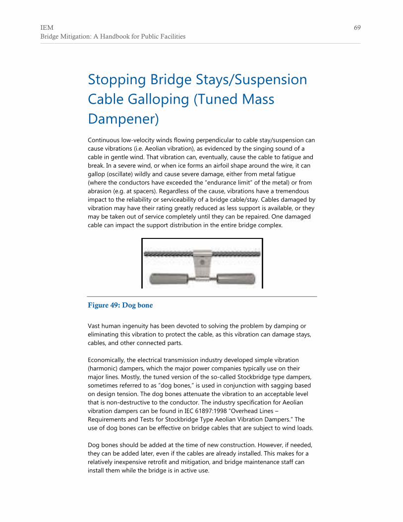
Stopping Bridge Stays/Suspension Cable Galloping (Tuned Mass Dampener) Continuous low-velocity winds flowing perpendicular to cable stay/suspension can cause vibrations (i.e. Aeolian vibration), as evidenced by the singing sound of a cable in gentle wind. That vibration can, eventually, cause the cable to fatigue and break. In a severe wind, or when ice forms an airfoil shape around the wire, it can gallop (oscillate) wildly and cause severe damage, either from metal fatigue (where the conductors have exceeded the “endurance limit” of the metal) or from abrasion (e.g. at spacers). Regardless of the cause, vibrations have a tremendous impact to the reliability or serviceability of a bridge cable/stay. Cables damaged by vibration may have their rating greatly reduced as less support is available, or they may be taken out of service completely until they can be repaired. One damaged cable can impact the support distribution in the entire bridge complex.
Figure 49: Dog bone
Vast human ingenuity has been devoted to solving the problem by damping or eliminating this vibration to protect the cable, as this vibration can damage stays, cables, and other connected parts. Economically, the electrical transmission industry developed simple vibration (harmonic) dampers, which the major power companies typically use on their major lines. Mostly, the tuned version of the so-called Stockbridge type dampers, sometimes referred to as “dog bones,” is used in conjunction with sagging based on design tension. The dog bones attenuate the vibration to an acceptable level that is non-destructive to the conductor. The industry specification for Aeolian vibration dampers can be found in IEC 61897:1998 “Overhead Lines – Requirements and Tests for Stockbridge Type Aeolian Vibration Dampers.” The use of dog bones can be effective on bridge cables that are subject to wind loads. Dog bones should be added at the time of new construction. However, if needed, they can be added later, even if the cables are already installed. This makes for a relatively inexpensive retrofit and mitigation, and bridge maintenance staff can install them while the bridge is in active use.

70 IEM Bridge Mitigation: A Handbook for Public Facilities
The area of the cable most prone to failure is where it attaches to the end of a cable. Typically, the dog bones are installed at the nearest anti-nodal point, i.e. the points of maximum oscillator of the cable, on either side of the clamp. Nominally, two dog bones are attached per cable span. However, more can be installed if the situation warrants this, especially for long cable spans. For smaller cables, a different dampener can be used, which is more effective than the Stockbridge style, called the spiral vibration damper. The spiral vibration damper has been successfully used for over three decades to control vibrations induced by wind for smaller sizes of cable and wire.
Figure 50: Spiral vibration damper
Effectiveness Very effective and economical
De facto standard of major electrical utilities, especially for transmissions and feeder lines
Easy to install
Can be retrofitted with bridge remaining in service
Can be installed well after a cable has been installed or repaired
Limitations Many bridge engineers are not aware of this technology

IEM 71 Bridge Mitigation: A Handbook for Public Facilities
Bridge in a Backpack Bridge in a Backpack is a type of construction that uses inflatable arches that are shipped in bags. This style of construction is quickly being accepted by engineering centers, public works departments, and by state departments of transportation (DOTs).
Figure 51: Bridge in a backpack
The process starts with flat, hollow carbon fiber tubes that can be easily rolled up and placed in a bag. Once the bags are shipped to the construction site, the carbon fiber material is inflated to form tubes. The tubes are placed over molds and shaped to a specific arch geometry. The tubes are then infused, in a vacuum process, with a durable polymer resin (vinyl ester) and allowed to cure/harden overnight. The tubes are placed into arches at the construction site and filled with self-consolidating concrete without steel rebars. As the concrete cures, the carbon fiber tube acts as impervious barrier against water, alkaline, salt, etc. The arches can be covered with corrugated composite material. Composite material can be used to form road decks in the area filled with fill, and on the deck paved to provide the final wearing road surface. Once casted, the tube will now act as the bridge superstructure, as a stay in place form. The tubes have twice the strength of steel, allowing the tubes to be strong enough and stiff enough to carry a concrete load.
Advantages Reduce material use
Reduce fabrication time

72 IEM Bridge Mitigation: A Handbook for Public Facilities
Reduce transportation time
Accelerate construction time
Lifetime may be 2 or 3 times that of a conventional bridge
Provide redundancy that significantly increases safety factor
No maintenance is required for tubes. Concrete inside is not exposed to environmental elements ever. There is no concrete spalling.
Reduce carbon footprint.
Adoptable to a variety of site locations, lends itself to multiple spans
Effectiveness Overall reduction in cost, material, fabrication and transportation time.
Greatly extended lifecycle.
Faster (less than half time of conventional) and more durable way to build bridge.
Limitations Lack of industry-wide knowledge of its use, especially infrastructure
owners like counties.
Need educated contractor who knows the technology.

IEM 73 Bridge Mitigation: A Handbook for Public Facilities
Bridge: Seismic Retrofit Seismic bridge retrofitting is the modification of a bridge structure to make it more robustly resilient to earthquakes movements, such as soil failure, ground motion, etc. Soft Rivets Many older bridges were built using red-hot rivets pressed into pre-drilled holes. The hot rivets are then peened over using a pneumonic hammer braced against a bucking bar resting on the rivet head. The rivets remain in soft/annealed condition after it cools. The steel plate, although produced hot rolled and quenched, remains hardened. When a load is pressed, the harder steel plate will guillotine the softer rivers, resulting in catastrophic failure of the connection, and possibly the bridge. The failure of poor grade rivets doomed the Titanic. Bridge Attachments Small bridges commonly have spans that are anchored to an abutment at one end, and attached to rockers at the other ends. This allows change in length of the span, performed with an expansion joint on top. For example, the Golden Gate Bridge expands 6 feet on a typical day. Under violent ground motion, rockers may jump from tracks, to extend beyond track limits, causing bridges to either become misaligned or to fail completely. Suspension Bridges Decks While suspension bridge decks are designed to move side to side under windy conditions, the motion generated by an earthquake may exceed design loading. This may result in damage to road surfaces or bridge bearings, or elastic deformation/breakage of bridge components. Lattice beams, Girders, Bridge Ties Lattice girders are generally formed by two I-beams/flat straps/angle stocks placed in a crisscross lattice.
Figure 52: Lattice strut

74 IEM Bridge Mitigation: A Handbook for Public Facilities
Solutions Rivets can be replaced with high-strength alloy bolts and nuts. Old rivets are cut out with an oxygen torch and their hold reamed. New bolts are not subject to plasticity of the old rivet, or the brittleness of standard off-the-shelf bolts. For example, the Golden Gate Bridge originally had 1 million rivets, which require continuous replacement of corroded rivets. Attachments can be improved by adding high strength steel restraints that clamp to the beam and allow for sliding under extreme conditions while damping the motion. Many suspension bridges use harmonic dampeners, such as hydraulic devices, or clamped sliding connectors, in addition to a cross bracing. Lattice beams, girders, or bridge ties can be replaced with plate members to form box members.
Figure 53: Bridge boxed lattice

IEM 75 Bridge Mitigation: A Handbook for Public Facilities
Concrete: Epoxy Asphalt Polymer Epoxy Asphalt Concrete is an excellent choice for durable bridge road surfaces as proven over a span of 45 years Since the 1960s, 225 thousand tons have been applied as bridge decking, equaling a total of 120 million square feet. The poster child of epoxy asphalt polymer is the San Francisco Oakland Bay Bridge, where the decking has survived 150 thousand cars a day with more than five lanes running in each direction. The wear layer is only 0.75 inches thick and has experienced 36 years of heavy traffic, or the equivalent of 360 plus million vehicles. Traffic has not been interrupted by periodic re-paving and the lightweight surface has reduced stress impact to the bridge.
Figure 54: San Francisco-Oakland Bay Bridge
Common uses include:
Use of a light weight, thin overlay wear surface (0.75 to 2 inches) for replacement or repair, or for new construction
Use for orthotropic steel deck where a strong, flexible deck characteristic is highly desirable
Use in extreme climates
Use with very heavily loaded trucks Other features:
Surface is highly impervious, which reduces underlying steel deck corrosion
Ability to bond, and stay bonded at elevated surface temperatures
Long lasting and elastic

76 IEM Bridge Mitigation: A Handbook for Public Facilities
Can be used as thin overlay when weight is a limiting factor
Traffic can resume within 2 to 4 hours (for light traffic condition) of installation
Three to four times stronger than conventional asphalt concrete mixes
Will not oxidize or harden as it ages (unlike conventional asphalt)
Additional lightweight aggregate is acceptable if low pavement weight is required
Little or no shrinkage during curing process
Will not rut or shove, even under extreme condition from overloaded semi-trucks
The two-phase epoxy asphalt binder is a thermoset polymer; that is, it will not melt after it has cured. This offers a significant advantage because conventional asphalts are thermoplastic polymers that readily melt at elevated temperatures, which can lead to delamination failures. Freshly laid epoxy asphalt pavement is not subject to rutting or shoving because the polymeric curing process is advanced during batching to a state of high stability. Thus, the dense-graded mix can be designed with a low void content without the danger of bleeding or flushing. The result is an extremely waterproof pavement that can be opened quickly.
Effectiveness Low maintenance, much longer life, light weight, flexible, very strong, and
prevents corrosion
Reduces loading of bridge (weight of re-surfacing has led to bridge failure)
Limitations Lack of industry-wide knowledge of its use
Higher initial cost

IEM 77 Bridge Mitigation: A Handbook for Public Facilities
Railroad: Wood versus Concrete Ties Even today, rail ties made of wood are the chosen standard for railroads. When chemically impregnated, they have a relatively long lifespan and can be used on almost any type of bridge since the spikes are hammered into ties, meaning that they can be used anywhere. However, they are still susceptible to rot, physical damage, and fire when fuel oil soaked from locomotive dripping. Generally, they have a lifespan of 20-30 years.
Figure 55: Concrete rail ties
Despite the traditional use of wood ties, concrete ties are becoming more commonly used. Concrete ties are more rigid than their wood counterparts, and they will not rot. They are also designed to expand and contract in unison with the welded rail they braced. Assuming no failures, they should have a life span exceeding 50 years. Using concrete allows for higher track speed as they do not need periodic maintenance like wood ties require. Since the track is more rigid, the locomotive uses less fuel to pull across a bridge. The advantage to using wood is that it costs around 35% less, with wood ties costing approximately $28 each and concrete ties approximately $41. However, this lower price is only for the initial cost. The overall cost of wooden ties is significantly more than concrete ties because of the cost of maintenance.
Effectiveness Significant longer lifespan
There is a chance that wooden ties may eventually be outlawed, thus forcing massive replacement with concrete ties

78 IEM Bridge Mitigation: A Handbook for Public Facilities
Reduces the need for maintenance work on tracks, which impacts the structure because of the heavy weight from maintenance equipment. While concrete ties are heavier, the weight of maintenance equipment has a much larger impact on structural integrity.
Limitations Requires custom hardware to hold rail to ties
Requires machinery to be adjusted or layered
Initially more expensive
Needs proper air entrainment (5-7%) for freeze-thaw resistance