ieee p802.15.4e/d0.01 draft standard
TRANSCRIPT
IEEE P802.15.4e/D0.01, (15-09/604/r6), 2010-03-08
Copyright © 2010 IEEE. All rights reserved. This is an unapproved IEEE Standards Draft, subject to change.
i
IEEE P802.15 1
Wireless Personal Area Networks 2 3
Project IEEE P802.15 Working Group for Wireless Personal Area Networks (WPANs)
Title IEEE Std 802.15.4e-D0.01/r5
Date Submitted
2010/03/08
Source [Ludwig Winkel, Zafer Sahinoglu, Liang Li], and fed by the following subgroups: TSCH, FA, E-GTS, Low-Energy, Short-Header+Security]
Voice: [] E-mail: [[email protected],] [[email protected],] [[email protected]]
Re: []
Abstract [1st draft IEEE Std 802.15.4e-D0.01 based on submissions of: 1) TSCH-, LL-, DSME-, LE-, security-and-efficiency-enhancements-subgroups of TG4e, 2) Fast Association, Metrixs, Enhanced Beacon request, and 3) TG4f RFID (Blink Frame (BF)).
Changes r4 to r5 are based on the following contributions: 1) Tim Godfrey, Metrics, 15-09-0734-03-004e-enhanced-mac-metrics.doc 2) M.Bahr, LL, 15-09-0604-05-004e-802_15_4e_D0_01_20100119_01-fa-00.zip; 3) Jonathan, TSCH improvements, 15-09-0833-00-004e-revision-to-mac-enhancement-for-tsch.doc and 15-09-0833-01-004e-revision-to-mac-enhancement-for-tschLW.doc; 4) Wei , LE, 10-0048-r2; 5) Partly as far discussed at 2010-01-21: René Struik 15-08-0848-07-004e-security-and-efficiency-enhancements-overview.doc; 6) Liang Lee DSME 15-09-0604-05-004e-802_15_4e_D0_01_20100120-Qin-Fum-Lee.doc
Changes r5 to r6 are based on the following contributions: 1) Betty Zhao; Fast Association (based upon 604-05)_20090203.doc 2) Editorial improvements of Ludwig WInkel. 3) Document provided by René Struik “editorial fixes to 09-0604r05 -v2 (Rene Struik, February 24,
2010).doc” with revisions of Ludwig Winkel. 4) Document provided by René Struik “15-08-0848-08-004e-security-and-efficiency-enhancements-
overview.doc”. 5) Email provided by Michael Bahr. 6) Email with attachment provided by Jonathan Simon “15-09-0833-02-004e-revision-to-mac-
enhancement-for-tsch(draft).doc” ]
Purpose []
Notice This document has been prepared to assist the IEEE P802.15. It is offered as a basis for discussion and is not binding on the contributing individual(s) or organization(s). The material in this document is subject to change in form and content after further study. The contributor(s) reserve(s) the right to add, amend or withdraw material contained herein.
Release The contributor acknowledges and accepts that this contribution becomes the property of IEEE and may be made publicly available by P802.15.

2010-03-08, (15-09/604/r6), IEEE P802.15.4e/D0.01
Copyright © 2010 IEEE. All rights reserved. This is an unapproved IEEE Standards Draft, subject to change.
ii
1
IEEE P802.15.4e™/D0.01 2
Draft Standard for Information 3
technology— Telecommunications 4
and information exchange between 5
systems— Local and metropolitan 6
area networks— Specific 7
requirements— Part 15.4: Wireless 8
Medium Access Control (MAC) and 9
Physical Layer (PHY) Specifications 10
for Low-Rate Wireless Personal Area 11
Networks (WPANs) Amendment 1: 12
Add MAC enhancements for 13
industrial applications and CWPAN 14
Prepared by the LAN/MAN Standards Committee Working Group of the 15
IEEE Computer Society Committee 16
Copyright © 2009 by the Institute of Electrical and Electronics Engineers, Inc. 17 Three Park Avenue 18 New York, New York 10016-5997, USA 19 All rights reserved. 20 This document is an unapproved draft of a proposed IEEE Standard. As such, this document is subject to 21 change. USE AT YOUR OWN RISK! Because this is an unapproved draft, this document must not be 22 utilized for any conformance/compliance purposes. Permission is hereby granted for IEEE Standards 23 Committee participants to reproduce this document for purposes of international standardization 24 consideration. Prior to adoption of this document, in whole or in part, by another standards development 25

IEEE P802.15.4e/D0.01, (15-09/604/r6), 2010-03-08
Copyright © 2010 IEEE. All rights reserved. This is an unapproved IEEE Standards Draft, subject to change.
iii
organization, permission must first be obtained from the IEEE Standards Activities Department 1 ([email protected]). Other entities seeking permission to reproduce this document, in whole or in part, must 2 also obtain permission from the IEEE Standards Activities Department. 3 IEEE Standards Activities Department 4 445 Hoes Lane 5 Piscataway, NJ 08854, USA 6

2010-03-08, (15-09/604/r6), IEEE P802.15.4e/D0.01
Copyright © 2010 IEEE. All rights reserved. This is an unapproved IEEE Standards Draft, subject to change.
iv
Abstract: First draft of 802 WG15 TG4e. Amendment to IEEE Std 802.15.4-2006 1 Keywords: Amendment for application domains like Process automation, Low latency, 2 Commercial, and enhancements for Security, low energy, etc. 3 4
• 5
The Institute of Electrical and Electronics Engineers, Inc. 3 Park Avenue, New York, NY 10016-5997, USA Copyright © 200X by the Institute of Electrical and Electronics Engineers, Inc. All rights reserved. Published XX Month XXXX. Printed in the United States of America. IEEE is a registered trademark in the U.S. Patent & Trademark Office, owned by the Institute of Electrical and Electronics Engineers, Incorporated. PDF: ISBN 978-0-XXXX-XXXX-X STDXXXXX Print: ISBN 978-0-XXXX-XXXX-X STDPDXXXXX No part of this publication may be reproduced in any form, in an electronic retrieval system or otherwise, without the prior written permission of the publisher.

IEEE P802.15.4e/D0.01, (15-09/604/r6), 2010-03-08
Copyright © 2010 IEEE. All rights reserved. This is an unapproved IEEE Standards Draft, subject to change.
v
This page is left blank intentionally. 1

2010-03-08, (15-09/604/r6), IEEE P802.15.4e/D0.01
Copyright © 2010 IEEE. All rights reserved. This is an unapproved IEEE Standards Draft, subject to change.
iv
Introduction 1
This introduction is not part of IEEE P802.15.4e/D0.01, Draft Standard for Information technology— 2 Telecommunications and information exchange between systems— Local and metropolitan area 3 networks— Specific requirements— Part 15.4: Wireless Medium Access Control (MAC) and Physical 4 Layer (PHY) Specifications for Low-Rate Wireless Personal Area Networks (WPANs) Amendment 1: 5 Add MAC enhancements for industrial applications and CWPAN. 6
Notice to users 7
Text formatted as this line means an editor note and will be removed before 8 publication. 9
Laws and regulations 10
Users of these documents should consult all applicable laws and regulations. Compliance with the provisions 11 of this standard does not imply compliance to any applicable regulatory requirements. Implementers of the 12 standard are responsible for observing or referring to the applicable regulatory requirements. IEEE does not, 13 by the publication of its standards, intend to urge action that is not in compliance with applicable laws, and 14 these documents may not be construed as doing so. 15
Copyrights 16
This document is copyrighted by the IEEE. It is made available for a wide variety of both public and private 17 uses. These include both use, by reference, in laws and regulations, and use in private self-regulation, 18 standardization, and the promotion of engineering practices and methods. By making this document 19 available for use and adoption by public authorities and private users, the IEEE does not waive any rights in 20 copyright to this document. 21
Updating of IEEE documents 22
Users of IEEE standards should be aware that these documents may be superseded at any time by the 23 issuance of new editions or may be amended from time to time through the issuance of amendments, 24 corrigenda, or errata. An official IEEE document at any point in time consists of the current edition of the 25 document together with any amendments, corrigenda, or errata then in effect. In order to determine whether 26 a given document is the current edition and whether it has been amended through the issuance of 27 amendments, corrigenda, or errata, visit the IEEE Standards Association web site at 28 http://ieeexplore.ieee.org/xpl/standards.jsp, or contact the IEEE at the address listed previously. 29
For more information about the IEEE Standards Association or the IEEE standards development process, 30 visit the IEEE-SA web site at http://standards.ieee.org. 31
Errata 32
Errata, if any, for this and all other standards can be accessed at the following URL: 33 http://standards.ieee.org/reading/ieee/updates/errata/index.html. Users are encouraged to check this URL for 34 errata periodically. 35
Interpretations 36
Current interpretations can be accessed at the following URL: http://standards.ieee.org/reading/ieee/interp/ 37 index.html. 38

IEEE P802.15.4e/D0.01, (15-09/604/r6), 2010-03-08
Copyright © 2010 IEEE. All rights reserved. This is an unapproved IEEE Standards Draft, subject to change.
v
Patents 1
Attention is called to the possibility that implementation of this standard may require use of subject matter 2 covered by patent rights. By publication of this standard, no position is taken with respect to the existence or 3 validity of any patent rights in connection therewith. The IEEE is not responsible for identifying Essential 4 Patent Claims for which a license may be required, for conducting inquiries into the legal validity or scope 5 of Patents Claims or determining whether any licensing terms or conditions provided in connection with 6 submission of a Letter of Assurance, if any, or in any licensing agreements are reasonable or non-7 discriminatory. Users of this standard are expressly advised that determination of the validity of any patent 8 rights, and the risk of infringement of such rights, is entirely their own responsibility. Further information 9 may be obtained from the IEEE Standards Association. 10
Participants 11
At the time this draft standard was submitted to the IEEE-SA Standards Board for approval, the LAN/MAN 12 Standards Committee Working Group had the following membership: 13
Bob Heile, Chair 14 Pat Kinney, Vice Chair 15
16 Participant1 17 Participant2 18 Participant3 19
Participant4 20 Participant5 21 Participant6 22
Participant7 23 Participant8 24 Participant9 25
26 27 The following members of the [individual/entity] balloting committee voted on this standard. Balloters may 28 have voted for approval, disapproval, or abstention. 29 30 (to be supplied by IEEE) 31 32 Participant1 33 Participant2 34 Participant3 35 Participant4 36 Participant5 37 Participant6 38 Participant7 39 Participant8 40 Participant9 41

IEEE P802.15.4e/D0.01, (15-09/604/r6), 2010-03-08
Copyright © 2010 IEEE. All rights reserved. This is an unapproved IEEE Standards Draft, subject to change.
v
Contents 1
1................................................................................................................................................................2 2
2................................................................................................................................................................2 3
3. Definitions ............................................................................................................................................2 4
4. Acronyms and abbreviations ................................................................................................................2 5
5. General description...............................................................................................................................3 6 5.1 Introduction.....................................................................................................................................3 7 5.2 Components of the IEEE 802.15.4 WPAN.....................................................................................3 8 5.3 Network topologies.........................................................................................................................3 9
5.3.1 Star network formation.............................................................................................................3 10 5.3.2 Peer-to-peer network formation................................................................................................3 11 5.3.3 LL-Star network for wireless low latency networks.................................................................4 12
5.3.3.1 General ........................................................................................................................................... 4 13 5.3.3.2 TDMA Access................................................................................................................................ 4 14 5.3.3.3 Addressing ..................................................................................................................................... 4 15 5.3.3.4 Network Topology ......................................................................................................................... 4 16
5.4 Architecture ....................................................................................................................................5 17 5.5 Functional overview........................................................................................................................5 18
5.5.1 Superframe structure ................................................................................................................5 19 5.5.1.1 General ........................................................................................................................................... 5 20 5.5.1.2 Superframe structure based on Beacons ......................................................................................... 5 21 5.5.1.3 Superframe structure based on Beacons with 1-octet MAC header................................................ 6 22
5.5.2 Data transfer model ..................................................................................................................7 23 5.5.2.1 Data transfer to a coordinator ......................................................................................................... 7 24 5.5.2.2 Data transfer from a coordinator .................................................................................................... 8 25
5.5.3 9 26 5.5.4 Improving probability of successful delivery ...........................................................................9 27
5.5.4.1 CSMA-CA mechanism................................................................................................................... 9 28 5.5.4.2 ALOHA mechanism for the UWB device...................................................................................... 9 29
5.5.5 9 30 5.5.5.1 Additional power saving features provided by the UWB PHY ...................................................... 9 31 5.5.5.2 Low-energy mechanisms................................................................................................................ 9 32
5.5.6 Security...................................................................................................................................10 33 5.5.7 10 34 5.5.8 10 35
5.6 Concept of primitives....................................................................................................................10 36 6. PHY specification...............................................................................................................................10 37
6.1 10 38 6.1.1 10 39 6.1.2 10 40
7. MAC sublayer specification ...............................................................................................................10 41 7.1 MAC sublayer service specification .............................................................................................10 42
7.1.1 MAC data service...................................................................................................................10 43 7.1.1.1 MCPS-DATA.request .................................................................................................................. 10 44
7.1.1.1.1 Semantics of the service primitive ....................................................................................... 11 45 7.1.1.1.1.1 General......................................................................................................................... 11 46 7.1.1.1.1.2 TSCH-Semantics of the service primitive.................................................................... 11 47
7.1.1.1.2 When generated ................................................................................................................... 12 48 7.1.1.1.3 Effect on receipt ................................................................................................................... 12 49
7.1.1.2 MCPS-DATA.confirm ................................................................................................................. 13 50 7.1.1.2.1 Semantics of the service primitive ....................................................................................... 13 51
7.1.1.2.1.1 General......................................................................................................................... 13 52 7.1.1.2.1.2 TSCH-Semantics of the service primitive.................................................................... 13 53
7.1.1.2.2 When generated ................................................................................................................... 13 54 7.1.1.2.3 Appropriate usage ................................................................................................................ 13 55

2010-03-08, (15-09/604/r6), IEEE P802.15.4e/D0.01
Copyright © 2010 IEEE. All rights reserved. This is an unapproved IEEE Standards Draft, subject to change.
vi
7.1.1.3 MCPS-DATA.indication.............................................................................................................. 14 1 7.1.2 MAC management service .....................................................................................................14 2
7.1.2.1 General ......................................................................................................................................... 14 3 7.1.2.2 TSCH-MAC management service................................................................................................ 14 4 7.1.2.3 LL-MAC management service ..................................................................................................... 14 5 7.1.2.4 DSME-MAC management service............................................................................................... 15 6
7.1.3 Association primitives ............................................................................................................15 7 7.1.3.1 MLME-ASSOCIATE.request ...................................................................................................... 15 8
7.1.3.1.1 Semantics of the service primitive ....................................................................................... 15 9 7.1.3.2 MLME-ASSOCIATE.indication.................................................................................................. 16 10
7.1.3.2.1 Semantics of the service primitive ....................................................................................... 16 11 7.1.3.3 MLME-ASSOCIATE.response.................................................................................................... 17 12
7.1.3.3.1 Semantics of the service primitive ....................................................................................... 17 13 7.1.3.4 MLME-ASSOCIATE.confirm ..................................................................................................... 17 14
7.1.3.4.1 Semantics of the service primitive ....................................................................................... 17 15 7.1.4 Disassociation primitives........................................................................................................18 16 7.1.5 Beacon notification primitive .................................................................................................18 17
7.1.5.1.1 Semantics of the service primitive ....................................................................................... 18 18 7.1.6 18 19 7.1.7 GTS management primitives ..................................................................................................18 20
7.1.7.1 ...................................................................................................................................................... 18 21 7.1.8 18 22 7.1.9 18 23 7.1.10 18 24 7.1.11 18 25 7.1.12 18 26 7.1.13 18 27 7.1.14 18 28 7.1.15 18 29 7.1.16 18 30 7.1.17 MAC enumeration description .............................................................................................19 31 7.1.18 TSCH-specific MAC sublayer service specification ............................................................19 32
7.1.18.1 MLME-SET-SLOTFRAME....................................................................................................... 19 33 7.1.18.1.1 MLME-SET-SLOTFRAME.request .................................................................................. 19 34
7.1.18.1.1.1 General....................................................................................................................... 19 35 7.1.18.1.1.2 Semantics................................................................................................................... 19 36 7.1.18.1.1.3 When generated ......................................................................................................... 20 37 7.1.18.1.1.4 Effect on receipt......................................................................................................... 20 38
7.1.18.1.2 MLME-SET-SLOTFRAME.confirm................................................................................. 20 39 7.1.18.1.2.1 General....................................................................................................................... 20 40 7.1.18.1.2.2 Semantics................................................................................................................... 20 41 7.1.18.1.2.3 When generated ......................................................................................................... 21 42 7.1.18.1.2.4 Effect on receipt......................................................................................................... 21 43
7.1.18.2 MLME-SET-LINK..................................................................................................................... 21 44 7.1.18.2.1 MLME-SET-LINK.request ................................................................................................ 21 45
7.1.18.2.1.1 General....................................................................................................................... 21 46 7.1.18.2.1.2 Semantics................................................................................................................... 21 47 7.1.18.2.1.3 When generated ......................................................................................................... 22 48 7.1.18.2.1.4 Effect on receipt......................................................................................................... 22 49
7.1.18.2.2 MLME-SET-LINK.confirm............................................................................................... 23 50 7.1.18.2.2.1 General....................................................................................................................... 23 51 7.1.18.2.2.2 Semantics................................................................................................................... 23 52 7.1.18.2.2.3 When generated ......................................................................................................... 23 53 7.1.18.2.2.4 Effect on receipt......................................................................................................... 23 54
7.1.18.3 MLME-TSCH-MODE ............................................................................................................... 24 55 7.1.18.3.1 MLME-TSCH-MODE.request........................................................................................... 24 56
7.1.18.3.1.1 Semantics................................................................................................................... 24 57 7.1.18.3.1.2 When generated ......................................................................................................... 24 58 7.1.18.3.1.3 Effect on receipt......................................................................................................... 24 59
7.1.18.3.2 MLME-TSCH-MODE.confirm.......................................................................................... 24 60 7.1.18.3.2.1 Semantics................................................................................................................... 24 61 7.1.18.3.2.2 When generated ......................................................................................................... 25 62 7.1.18.3.2.3 Effect on receipt......................................................................................................... 25 63
7.1.18.4 MLME-LISTEN......................................................................................................................... 25 64 7.1.18.4.1 MLME-LISTEN.request .................................................................................................... 25 65
7.1.18.4.1.1 Semantics................................................................................................................... 25 66 7.1.18.4.1.2 When generated ......................................................................................................... 26 67 7.1.18.4.1.3 Effect on receipt......................................................................................................... 26 68

IEEE P802.15.4e/D0.01, (15-09/604/r6), 2010-03-08
Copyright © 2010 IEEE. All rights reserved. This is an unapproved IEEE Standards Draft, subject to change.
vii
7.1.18.4.2 MLME-LISTEN.confirm ................................................................................................... 26 1 7.1.18.4.2.1 Semantics................................................................................................................... 26 2 7.1.18.4.2.2 When generated ......................................................................................................... 27 3 7.1.18.4.2.3 Effect on receipt......................................................................................................... 27 4
7.1.18.5 MLME-ADVERTISE ................................................................................................................ 27 5 7.1.18.5.1 MLME-ADVERTISE.request............................................................................................ 27 6
7.1.18.5.1.1 Semantics................................................................................................................... 27 7 7.1.18.5.1.2 When generated ......................................................................................................... 28 8 7.1.18.5.1.3 Effect on receipt......................................................................................................... 28 9
7.1.18.5.2 ADVERTISE.indication..................................................................................................... 28 10 7.1.18.5.2.1 Semantics................................................................................................................... 28 11 7.1.18.5.2.2 When generated ......................................................................................................... 30 12 7.1.18.5.2.3 Effect on receipt......................................................................................................... 30 13
7.1.18.5.3 MLME-ADVERTISE.confirm........................................................................................... 30 14 7.1.18.5.3.1 Semantics................................................................................................................... 30 15 7.1.18.5.3.2 When generated ......................................................................................................... 30 16 7.1.18.5.3.3 Effect on receipt......................................................................................................... 31 17
7.1.18.6 MLME-KEEP-ALIVE ............................................................................................................... 31 18 7.1.18.6.1 MLME-KEEP-ALIVE.request........................................................................................... 31 19
7.1.18.6.1.1 Semantics................................................................................................................... 31 20 7.1.18.6.1.2 When generated ......................................................................................................... 31 21 7.1.18.6.1.3 Effect on receipt......................................................................................................... 31 22
7.1.18.6.2 MLME-KEEP-ALIVE.confirm.......................................................................................... 31 23 7.1.18.6.2.1 Semantics................................................................................................................... 31 24 7.1.18.6.2.2 When generated ......................................................................................................... 32 25 7.1.18.6.2.3 Effect on receipt......................................................................................................... 32 26
7.1.18.7 MLME-JOIN.............................................................................................................................. 32 27 7.1.18.7.1 MLME-JOIN.request ......................................................................................................... 32 28
7.1.18.7.1.1 Semantics................................................................................................................... 32 29 7.1.18.7.1.2 When generated ......................................................................................................... 33 30 7.1.18.7.1.3 Effect on receipt......................................................................................................... 33 31
7.1.18.7.2 MLME-JOIN.indication..................................................................................................... 33 32 7.1.18.7.2.1 Semantics................................................................................................................... 33 33 7.1.18.7.2.2 When generated ......................................................................................................... 34 34 7.1.18.7.2.3 Effect on receipt......................................................................................................... 34 35
7.1.18.7.3 MLME-JOIN.confirm ........................................................................................................ 34 36 7.1.18.7.3.1 Semantics................................................................................................................... 34 37 7.1.18.7.3.2 When generated ......................................................................................................... 34 38 7.1.18.7.3.3 Effect on receipt......................................................................................................... 34 39
7.1.18.8 MLME-ACTIVATE................................................................................................................... 35 40 7.1.18.8.1 MLME-ACTIVATE.request .............................................................................................. 35 41
7.1.18.8.1.1 Semantics................................................................................................................... 35 42 7.1.18.8.1.2 When generated ......................................................................................................... 36 43 7.1.18.8.1.3 Effect on receipt......................................................................................................... 36 44
7.1.18.8.2 MLME-ACTIVATE.indication.......................................................................................... 36 45 7.1.18.8.2.1 Semantics................................................................................................................... 36 46 7.1.18.8.2.2 When generated ......................................................................................................... 37 47 7.1.18.8.2.3 Effect on receipt......................................................................................................... 37 48
7.1.18.8.3 MLME-ACTIVATE.confirm............................................................................................. 37 49 7.1.18.8.3.1 Semantics................................................................................................................... 37 50 7.1.18.8.3.2 When generated ......................................................................................................... 37 51 7.1.18.8.3.3 Effect on receipt......................................................................................................... 38 52
7.1.18.9 MLME-DISASSOCIATE .......................................................................................................... 38 53 7.1.18.9.1 MLME-DISASSOCIATE.request...................................................................................... 38 54
7.1.18.9.1.1 Semantics................................................................................................................... 38 55 7.1.18.9.1.2 When generated ......................................................................................................... 38 56 7.1.18.9.1.3 Effect on receipt......................................................................................................... 38 57
7.1.18.9.2 MLME-DISASSOCIATE.indication ................................................................................. 38 58 7.1.18.9.2.1 Semantics................................................................................................................... 38 59 7.1.18.9.2.2 When generated ......................................................................................................... 39 60 7.1.18.9.2.3 Effect on receipt......................................................................................................... 39 61
7.1.18.9.3 MLME-DISASSOCIATE.confirm..................................................................................... 39 62 7.1.18.9.3.1 Semantics................................................................................................................... 39 63 7.1.18.9.3.2 When generated ......................................................................................................... 39 64 7.1.18.9.3.3 Effect on receipt......................................................................................................... 39 65
7.1.19 LL-specific MAC sublayer service specification .................................................................39 66 7.1.19.1 Primitives for Superframe Configuration of low latency networks ............................................ 40 67
7.1.19.1.1 General............................................................................................................................... 40 68 7.1.19.1.2 MLME-LL_NW.discovery ................................................................................................ 40 69
7.1.19.1.2.1 General....................................................................................................................... 40 70

2010-03-08, (15-09/604/r6), IEEE P802.15.4e/D0.01
Copyright © 2010 IEEE. All rights reserved. This is an unapproved IEEE Standards Draft, subject to change.
viii
7.1.19.1.2.2 Semantics of the Service Primitive ............................................................................ 40 1 7.1.19.1.2.3 Appropriate usage ...................................................................................................... 40 2 7.1.19.1.2.4 Effect on receipt......................................................................................................... 40 3
7.1.19.1.3 MLME-LL_NW.discovery_confirm.................................................................................. 41 4 7.1.19.1.3.1 General....................................................................................................................... 41 5 7.1.19.1.3.2 Semantics of the Service Primitive ............................................................................ 41 6 7.1.19.1.3.3 When generated ......................................................................................................... 41 7 7.1.19.1.3.4 Appropriate usage ...................................................................................................... 41 8
7.1.19.1.4 MLME-LL_NW.configuration .......................................................................................... 42 9 7.1.19.1.4.1 General....................................................................................................................... 42 10 7.1.19.1.4.2 Semantics of the Service Primitive ............................................................................ 42 11 7.1.19.1.4.3 Appropriate usage ...................................................................................................... 42 12 7.1.19.1.4.4 Effect on receipt......................................................................................................... 42 13
7.1.19.1.5 MLME-LL_NW.configuration_confirm ............................................................................ 42 14 7.1.19.1.5.1 General....................................................................................................................... 42 15 7.1.19.1.5.2 Semantics of the Service Primitive ............................................................................ 42 16 7.1.19.1.5.3 When generated ......................................................................................................... 43 17 7.1.19.1.5.4 Appropriate usage ...................................................................................................... 43 18
7.1.19.1.6 MLME-LL_NW.online...................................................................................................... 43 19 7.1.19.1.6.1 General....................................................................................................................... 43 20 7.1.19.1.6.2 Semantics of the Service Primitive ............................................................................ 43 21 7.1.19.1.6.3 Appropriate usage ...................................................................................................... 44 22 7.1.19.1.6.4 Effect on receipt......................................................................................................... 44 23
7.1.19.1.7 MLME-LL_NW.online_indication .................................................................................... 44 24 7.1.19.1.7.1 General....................................................................................................................... 44 25 7.1.19.1.7.2 Semantics of the Service Primitive ............................................................................ 44 26 7.1.19.1.7.3 When generated ......................................................................................................... 44 27 7.1.19.1.7.4 Appropriate usage ...................................................................................................... 45 28
7.1.20 DSME-specific MAC sublayer service specification ...........................................................45 29 7.1.20.1 MLME-DSME ........................................................................................................................... 45 30
7.1.20.1.1 General............................................................................................................................... 45 31 7.1.20.1.2 MLME-DSME.request....................................................................................................... 45 32
7.1.20.1.2.1 General....................................................................................................................... 45 33 7.1.20.1.2.2 Semantics................................................................................................................... 45 34 7.1.20.1.2.3 When generated ......................................................................................................... 46 35 7.1.20.1.2.4 Effect on receipt......................................................................................................... 46 36
7.1.20.1.3 MLME-DSME.confirm...................................................................................................... 49 37 7.1.20.1.3.1 General....................................................................................................................... 49 38 7.1.20.1.3.2 Semantics................................................................................................................... 49 39 7.1.20.1.3.3 When generated ......................................................................................................... 49 40 7.1.20.1.3.4 Effect on receipt......................................................................................................... 50 41
7.1.20.1.4 MLME-DSME.indication .................................................................................................. 50 42 7.1.20.1.4.1 General....................................................................................................................... 50 43 7.1.20.1.4.2 Semantics................................................................................................................... 50 44 7.1.20.1.4.3 When generated ......................................................................................................... 51 45 7.1.20.1.4.4 Effect on receipt......................................................................................................... 51 46
7.1.20.1.5 DSME management message sequence charts ................................................................... 51 47 7.1.20.2 MLME-DSME-START.............................................................................................................. 52 48
7.1.20.2.1 General............................................................................................................................... 52 49 7.1.20.2.2 MLME-DSME-START.request ......................................................................................... 52 50
7.1.20.2.2.1 General....................................................................................................................... 52 51 7.1.20.2.2.2 Semantics................................................................................................................... 52 52 7.1.20.2.2.3 Appropriate usage ...................................................................................................... 54 53 7.1.20.2.2.4 Effect on receipt......................................................................................................... 54 54
7.1.20.3 MAC DSME-data service .......................................................................................................... 54 55 7.1.20.3.1 General............................................................................................................................... 54 56 7.1.20.3.2 MCPS-DSME-DATA.request............................................................................................ 55 57
7.1.20.3.2.1 Appropriate usage ...................................................................................................... 55 58 7.1.20.3.2.2 Effect on receipt......................................................................................................... 55 59
7.1.20.4 MLME-DSMEinfo ..................................................................................................................... 55 60 7.1.20.4.1 DSME-Primitives for requesting DSME information ........................................................ 55 61 7.1.20.4.2 MLME-DSMEinfo.request ................................................................................................ 55 62
7.1.20.4.2.1 General....................................................................................................................... 55 63 7.1.20.4.2.2 Semantics................................................................................................................... 56 64 7.1.20.4.2.3 Appropriate usage ...................................................................................................... 56 65 7.1.20.4.2.4 Effect on receipt......................................................................................................... 56 66
7.1.20.4.3 MLME-DSMEinfo.confirm ............................................................................................... 57 67 7.1.20.4.3.1 General....................................................................................................................... 57 68 7.1.20.4.3.2 Semantics................................................................................................................... 57 69 7.1.20.4.3.3 When generated ......................................................................................................... 58 70

IEEE P802.15.4e/D0.01, (15-09/604/r6), 2010-03-08
Copyright © 2010 IEEE. All rights reserved. This is an unapproved IEEE Standards Draft, subject to change.
ix
7.1.20.4.3.4 Appropriate usage ...................................................................................................... 58 1 7.1.20.4.4 DSME information sequence chart .................................................................................... 58 2
7.1.20.5 MLME-DSME-LINKSTATUSRPT .......................................................................................... 59 3 7.1.20.5.1.1 General....................................................................................................................... 59 4
7.1.20.5.2 MLME-DSME-LINKSTATUSRPT.request...................................................................... 59 5 7.1.20.5.2.1 General....................................................................................................................... 59 6 7.1.20.5.2.2 Semantics................................................................................................................... 59 7 7.1.20.5.2.3 Appropriate usage ...................................................................................................... 60 8 7.1.20.5.2.4 Effect on receipt......................................................................................................... 60 9
7.1.20.5.3 MLME-DSME-LINKSTATUSRPT.confirm..................................................................... 60 10 7.1.20.5.3.1 General....................................................................................................................... 60 11 7.1.20.5.3.2 Semantics................................................................................................................... 60 12 7.1.20.5.3.3 When generated ......................................................................................................... 61 13 7.1.20.5.3.4 Effect on receipt......................................................................................................... 61 14
7.1.20.5.4 MLME-DSME-LINKSTATUSRPT.indication ................................................................. 61 15 7.1.20.5.4.1 General....................................................................................................................... 61 16 7.1.20.5.4.2 Semantics................................................................................................................... 61 17 7.1.20.5.4.3 When generated ......................................................................................................... 62 18 7.1.20.5.4.4 Effect on receipt......................................................................................................... 62 19
7.1.20.5.5 MLME-DSME-LINKSTATUSRPT message sequence charts .......................................... 62 20 7.1.20.6 DSME-Beacon notification primitive......................................................................................... 63 21
7.1.20.6.1 General............................................................................................................................... 63 22 7.1.20.6.2 MLME-DSME-BEACON-NOTIFY.indication ................................................................. 63 23
7.1.20.7 DSME-Primitives for channel scanning ..................................................................................... 63 24 7.1.20.7.1 General............................................................................................................................... 63 25 7.1.20.7.2 MLME-DSME-SCAN.request ........................................................................................... 63 26
7.1.20.7.2.1 General....................................................................................................................... 63 27 7.1.20.7.2.2 Semantics of the service primitive ............................................................................. 63 28 7.1.20.7.2.3 Appropriate usage ...................................................................................................... 64 29 7.1.20.7.2.4 Effect on receipt......................................................................................................... 64 30
7.1.20.7.3 MLME-DSME-SCAN.confirm.......................................................................................... 65 31 7.1.20.7.3.1 General....................................................................................................................... 65 32 7.1.20.7.3.2 Semantics of the service primitive ............................................................................. 65 33
7.1.21 LE-specific MAC sublayer service specification .................................................................65 34 7.1.21.1 General ....................................................................................................................................... 65 35 7.1.21.2 MLME-FRAME-ERROR.indication ......................................................................................... 65 36
7.1.21.2.1 General............................................................................................................................... 65 37 7.1.21.2.2 Semantics of the service primitive ..................................................................................... 66 38 7.1.21.2.3 When generated ................................................................................................................. 66 39 7.1.21.2.4 Appropriate usage .............................................................................................................. 66 40
7.1.22 FastA-MAC sublayer service specification ..........................................................................66 41 7.1.22.1 MLME-FAST-ASSOCIATE.request ......................................................................................... 66 42
7.1.22.1.1 General............................................................................................................................... 66 43 7.1.22.1.2 Semantics ........................................................................................................................... 66 44 7.1.22.1.3 Appropriate usage .............................................................................................................. 67 45 7.1.22.1.4 Effect on receipt ................................................................................................................. 67 46
7.2 MAC frame formats ......................................................................................................................67 47 7.2.1 General MAC frame format ...................................................................................................67 48
7.2.1.1 Frame Control field ...................................................................................................................... 67 49 7.2.1.1.1 Frame Type subfield ............................................................................................................ 68 50
7.2.1.1.1.1 Frame type identifier for full frame control field ......................................................... 69 51 7.2.1.1.1.2 Frame type identifier for short frame control field....................................................... 69 52
7.2.1.1.2 Security Enabled subfield .................................................................................................... 69 53 7.2.1.1.3 Frame Pending subfield........................................................................................................ 69 54 7.2.1.1.4 .............................................................................................................................................. 69 55 7.2.1.1.5 .............................................................................................................................................. 69 56 7.2.1.1.6 Destination Addressing Mode subfield ................................................................................ 69 57 7.2.1.1.7 Frame Version subfield ........................................................................................................ 69 58
7.2.1.1.7.1 Frame version subfield for long frame control field .................................................... 70 59 7.2.1.1.7.2 Frame version subfield for short frame control field.................................................... 70 60
7.2.1.1.8 Source Addressing Mode subfield ....................................................................................... 70 61 7.2.1.1.9 Short Frame Control Field Subfield ..................................................................................... 70 62
7.2.1.2 Sequence Number field ................................................................................................................ 70 63 7.2.1.3 Destination PAN Identifier field .................................................................................................. 71 64 7.2.1.4 Destination Address field ............................................................................................................. 71 65 7.2.1.5 Source PAN Identifier field.......................................................................................................... 71 66 7.2.1.6 Source Address field .................................................................................................................... 71 67 7.2.1.7 Auxiliary Security Header field.................................................................................................... 71 68 7.2.1.8 Frame Payload field ..................................................................................................................... 71 69

2010-03-08, (15-09/604/r6), IEEE P802.15.4e/D0.01
Copyright © 2010 IEEE. All rights reserved. This is an unapproved IEEE Standards Draft, subject to change.
x
7.2.1.9 FCS field ...................................................................................................................................... 71 1 7.2.1.10 Split payload subfield................................................................................................................. 71 2 7.2.1.11 Frame payload header field ........................................................................................................ 71 3
7.2.2 Format of individual frame types ...........................................................................................72 4 7.2.2.1 Beacon frame format .................................................................................................................... 72 5
7.2.2.1.1 Beacon frame MHR fields ................................................................................................... 72 6 7.2.2.2 Data frame format ........................................................................................................................ 72 7 7.2.2.3 Acknowledgment frame format.................................................................................................... 72 8
7.2.2.3.1 Acknowledgment frame MHR fields ................................................................................... 73 9 7.2.2.3.2 Acknowledgement frame payload fields .............................................................................. 74 10
7.2.2.3.2.1 General......................................................................................................................... 74 11 7.2.2.3.2.2 Acknowledgement control subfield ............................................................................. 74 12
7.2.2.4 MAC command frame format ...................................................................................................... 76 13 7.2.3 Frame compatibility ...............................................................................................................77 14 7.2.4 PA Frame Formats..................................................................................................................77 15 7.2.5 LL-Frame Formats .................................................................................................................77 16
7.2.5.1 Format of individual frame types with MHR of 1 octet ............................................................... 77 17 7.2.5.1.1 General................................................................................................................................. 77 18 7.2.5.1.2 Beacon frame format............................................................................................................ 77 19
7.2.5.1.2.1 General......................................................................................................................... 77 20 7.2.5.1.2.2 Beacon frame MHR fields ........................................................................................... 78 21 7.2.5.1.2.3 Flags / Beacon Payload in online mode ....................................................................... 78 22 7.2.5.1.2.4 Flags / Beacon payload for discovery and configuration mode ................................... 79 23
7.2.5.1.3 Data frame format ................................................................................................................ 80 24 7.2.5.1.3.1 General......................................................................................................................... 80 25 7.2.5.1.3.2 Data frame MHR fields................................................................................................ 80 26 7.2.5.1.3.3 Data Payload field........................................................................................................ 80 27
7.2.5.1.4 Acknowledgement frame format.......................................................................................... 80 28 7.2.5.1.4.1 General......................................................................................................................... 80 29 7.2.5.1.4.2 Acknowledgement frame MHR fields ......................................................................... 81 30 7.2.5.1.4.3 Acknowledgement Type field...................................................................................... 81 31 7.2.5.1.4.4 Acknowledgement Payload field ................................................................................. 81 32 7.2.5.1.4.5 Data Group ACK (GACK) .......................................................................................... 81 33 7.2.5.1.4.6 Secure Acknowledgement ........................................................................................... 82 34
7.2.5.1.5 MAC Command frame format ............................................................................................. 83 35 7.2.5.1.5.1 General......................................................................................................................... 83 36 7.2.5.1.5.2 MAC command frame MHR fields.............................................................................. 83 37 7.2.5.1.5.3 Command Payload field............................................................................................... 84 38
7.2.5.2 Frame Control field ...................................................................................................................... 84 39 7.2.5.2.1 General................................................................................................................................. 84 40 7.2.5.2.2 Frame Type subfield ............................................................................................................ 84 41 7.2.5.2.3 Security Enabled subfield .................................................................................................... 84 42 7.2.5.2.4 Sub Frame Type subfield ..................................................................................................... 84 43 7.2.5.2.5 Frame Version subfield ........................................................................................................ 84 44 7.2.5.2.6 Other subfields ..................................................................................................................... 85 45
7.2.6 DSME-Frame Formats ...........................................................................................................85 46 7.2.6.1 General MAC frame format ......................................................................................................... 85 47 7.2.6.2 Format of individual frame types ................................................................................................. 85 48
7.2.6.2.1 General................................................................................................................................. 85 49 7.2.6.2.2 Beacon frame format............................................................................................................ 85 50
7.2.6.2.2.1 General......................................................................................................................... 85 51 7.2.6.2.2.2 Beacon frame MHR fields ........................................................................................... 86 52 7.2.6.2.2.3 Superframe Specification field..................................................................................... 86 53 7.2.6.2.2.4 GTS Specification field................................................................................................ 86 54 7.2.6.2.2.5 GTS Directions field.................................................................................................... 86 55 7.2.6.2.2.6 GTS List field .............................................................................................................. 86 56 7.2.6.2.2.7 Pending Address Specification field ............................................................................ 86 57 7.2.6.2.2.8 Address List field......................................................................................................... 86 58 7.2.6.2.2.9 Beacon Payload field ................................................................................................... 87 59 7.2.6.2.2.10 DSME Superframe Specification field....................................................................... 87 60 7.2.6.2.2.11 Channel Hopping Specification field ......................................................................... 88 61 7.2.6.2.2.12 Time Synchronization Specification field.................................................................. 88 62 7.2.6.2.2.13 Beacon Bitmap field .................................................................................................. 88 63
7.2.6.2.3 Data frame format ................................................................................................................ 89 64 7.2.6.2.4 Acknowledgment frame format ........................................................................................... 89 65 7.2.6.2.5 Data Group ACK (GACK)................................................................................................... 89 66 7.2.6.2.6 MAC command frame format .............................................................................................. 90 67
7.2.7 Extensibility Frame ................................................................................................................90 68 7.2.7.1 General ......................................................................................................................................... 90 69

IEEE P802.15.4e/D0.01, (15-09/604/r6), 2010-03-08
Copyright © 2010 IEEE. All rights reserved. This is an unapproved IEEE Standards Draft, subject to change.
xi
7.2.7.2 Frame Control field ...................................................................................................................... 90 1 7.2.7.2.1 General................................................................................................................................. 90 2 7.2.7.2.2 Frame Type subfield ............................................................................................................ 91 3 7.2.7.2.3 Security Enabled subfield .................................................................................................... 91 4 7.2.7.2.4 Sub Frame Type subfield ..................................................................................................... 91 5 7.2.7.2.5 Frame Version subfield ........................................................................................................ 91 6 7.2.7.2.6 Other subfields ..................................................................................................................... 91 7
7.2.8 Blink frame format .................................................................................................................91 8 7.2.8.1 General ......................................................................................................................................... 91 9 7.2.8.2 Blink frame MHR fields............................................................................................................... 92 10 7.2.8.3 Blink frame payload field............................................................................................................. 92 11
7.3 MAC command frames.................................................................................................................92 12 7.3.1 Association request command................................................................................................93 13 7.3.2 Association response command..............................................................................................94 14
7.3.2.1 MHR fields................................................................................................................................... 94 15 7.3.2.2 Short Address field....................................................................................................................... 94 16 7.3.2.3 Association Status field ................................................................................................................ 94 17
7.3.3 94 18 7.3.4 94 19 7.3.5 94 20 7.3.6 94 21 7.3.7 94 22 7.3.8 Coordinator realignment command ........................................................................................94 23 7.3.9 GTS request command ...........................................................................................................94 24 7.3.10 TSCH-commands .................................................................................................................94 25
7.3.10.1 Advertisement command............................................................................................................ 94 26 7.3.10.1.1 General............................................................................................................................... 94 27 7.3.10.1.2 MHR field .......................................................................................................................... 95 28 7.3.10.1.3 Command Frame Identifier field........................................................................................ 95 29 7.3.10.1.4 Timing Information field.................................................................................................... 95 30 7.3.10.1.5 Security Control field......................................................................................................... 95 31 7.3.10.1.6 Join Control field ............................................................................................................... 95 32 7.3.10.1.7 Timeslot Template ............................................................................................................. 96 33 7.3.10.1.8 Timeslot Template ............................................................................................................. 96 34 7.3.10.1.9 Hopping sequence .............................................................................................................. 96 35
7.3.10.1.9.1 General....................................................................................................................... 96 36 7.3.10.1.9.2 Hopping Sequence Length ......................................................................................... 96 37 7.3.10.1.9.3 Hopping Sequence ..................................................................................................... 97 38 7.3.10.1.9.4 Current Hop in Sequence ........................................................................................... 97 39
7.3.10.1.10 Channel Page/Map Length field....................................................................................... 97 40 7.3.10.1.11 Channel Page field ........................................................................................................... 97 41 7.3.10.1.12 Number of Slotframes field.............................................................................................. 97 42 7.3.10.1.13 Slotframe Information and Links (for each slotframe) field............................................. 97 43 7.3.10.1.14 General............................................................................................................................. 97 44 7.3.10.1.15 Slotframe ID subfield....................................................................................................... 97 45 7.3.10.1.16 Slotframe Size subfield .................................................................................................... 98 46 7.3.10.1.17 Number of Links subfield ................................................................................................ 98 47 7.3.10.1.18 Link Information (for each link) subfield......................................................................... 98 48 7.3.10.1.19 Timeslot subfield.............................................................................................................. 98 49 7.3.10.1.20 Channel Offset Information subfield................................................................................ 98 50 7.3.10.1.21 Link Option subfield ........................................................................................................ 98 51 7.3.10.1.22 MIC.................................................................................................................................. 98 52
7.3.10.2 Join command ............................................................................................................................ 98 53 7.3.10.2.1 General............................................................................................................................... 98 54 7.3.10.2.2 MHR fields......................................................................................................................... 99 55 7.3.10.2.3 Command Frame Identifier field........................................................................................ 99 56 7.3.10.2.4 Capability Information field............................................................................................... 99 57 7.3.10.2.5 Clock Accuracy Capability field ........................................................................................ 99 58 7.3.10.2.6 Join Security Information field......................................................................................... 100 59 7.3.10.2.7 Number of Neighbor field ................................................................................................ 100 60 7.3.10.2.8 Neighbor field .................................................................................................................. 100 61 7.3.10.2.9 MIC.................................................................................................................................. 100 62
7.3.10.3 Activate command.................................................................................................................... 100 63 7.3.10.3.1 General............................................................................................................................. 100 64 7.3.10.3.2 MHR ................................................................................................................................ 101 65 7.3.10.3.3 Command Frame Identifier field...................................................................................... 101 66 7.3.10.3.4 Short Address field........................................................................................................... 101 67 7.3.10.3.5 Number of Links field...................................................................................................... 101 68 7.3.10.3.6 Link field.......................................................................................................................... 101 69

2010-03-08, (15-09/604/r6), IEEE P802.15.4e/D0.01
Copyright © 2010 IEEE. All rights reserved. This is an unapproved IEEE Standards Draft, subject to change.
xii
7.3.10.3.7 Activate Security Information field.................................................................................. 102 1 7.3.10.3.8 MIC.................................................................................................................................. 102 2
7.3.11 LL-commands ....................................................................................................................102 3 7.3.11.1 Discover Response command................................................................................................... 102 4
7.3.11.1.1 General............................................................................................................................. 102 5 7.3.11.1.2 7.3.10.1 MHR fields......................................................................................................... 102 6
7.3.11.1.2.1 General..................................................................................................................... 102 7 7.3.11.1.2.2 Using MAC command frames ................................................................................. 102 8 7.3.11.1.2.3 Using MAC command frames with shortened frame control................................... 103 9
7.3.11.1.3 7.3.10.2 Command Frame Identifier field ........................................................................ 103 10 7.3.11.1.4 7.3.10.3 Discovery Parameters field ................................................................................ 103 11
7.3.11.2 Configuration Response Frame ................................................................................................ 103 12 7.3.11.2.1 General............................................................................................................................. 103 13 7.3.11.2.2 MHR fields....................................................................................................................... 103 14 7.3.11.2.3 Using MAC command frames.......................................................................................... 104 15
7.3.11.2.3.1 General..................................................................................................................... 104 16 7.3.11.2.3.2 Using MAC command frames with short frame control .......................................... 104 17
7.3.11.2.4 Command Frame Identifier field...................................................................................... 104 18 7.3.11.2.5 Configuration Parameters field ........................................................................................ 104 19
7.3.11.3 Configuration Request Frame................................................................................................... 104 20 7.3.11.3.1 General............................................................................................................................. 104 21 7.3.11.3.2 MHR fields....................................................................................................................... 105 22
7.3.11.3.2.1 General..................................................................................................................... 105 23 7.3.11.3.2.2 Using MAC command frames ................................................................................. 105 24 7.3.11.3.2.3 Using MAC command frames with short frame control .......................................... 105 25
7.3.11.3.3 Command Frame Identifier field...................................................................................... 105 26 7.3.11.3.4 Configuration Parameters field ........................................................................................ 105 27
7.3.11.4 Clear to Send (CTS) Shared Group Frame ............................................................................... 106 28 7.3.11.4.1 General............................................................................................................................. 106 29 7.3.11.4.2 MHR fields....................................................................................................................... 106 30 7.3.11.4.3 Command Frame Identifier field...................................................................................... 106 31 7.3.11.4.4 Network ID field .............................................................................................................. 106 32
7.3.11.5 Request to Send (RTS) Frame.................................................................................................. 106 33 7.3.11.5.1 General............................................................................................................................. 106 34 7.3.11.5.2 MHR fields....................................................................................................................... 107 35 7.3.11.5.3 Command Frame Identifier field...................................................................................... 107 36 7.3.11.5.4 Short Originator Address ................................................................................................. 107 37 7.3.11.5.5 Network ID field .............................................................................................................. 107 38
7.3.11.6 Clear to Send (CTS) Frame ...................................................................................................... 107 39 7.3.11.6.1 General............................................................................................................................. 107 40 7.3.11.6.2 MHR fields....................................................................................................................... 108 41 7.3.11.6.3 Command Frame Identifier field...................................................................................... 108 42 7.3.11.6.4 Short Destination Address................................................................................................ 108 43 7.3.11.6.5 Network ID field .............................................................................................................. 108 44
7.3.12 DSME-commands ..............................................................................................................108 45 7.3.12.1 General ..................................................................................................................................... 108 46 7.3.12.2 DSME-Association request command...................................................................................... 108 47
7.3.12.2.1 General............................................................................................................................. 108 48 7.3.12.2.2 MHR fields....................................................................................................................... 108 49 7.3.12.2.3 Capability Information field............................................................................................. 109 50 7.3.12.2.4 Channel Offset field ......................................................................................................... 109 51
7.3.12.3 DSME-Association respond command..................................................................................... 109 52 7.3.12.3.1 General............................................................................................................................. 109 53 7.3.12.3.2 MHR fields....................................................................................................................... 109 54 7.3.12.3.3 Short Address field........................................................................................................... 109 55 7.3.12.3.4 Association Status field.................................................................................................... 109 56 7.3.12.3.5 Channel Hopping Sequence Length field......................................................................... 109 57 7.3.12.3.6 Channel Hopping Sequence field ..................................................................................... 110 58
7.3.12.4 DSME handshake command .................................................................................................... 110 59 7.3.12.4.1 General............................................................................................................................. 110 60 7.3.12.4.2 DSME-MHR fields .......................................................................................................... 110 61 7.3.12.4.3 DSME Characteristics fields ............................................................................................ 110 62 7.3.12.4.4 DSME Descriptor field .................................................................................................... 111 63 7.3.12.4.5 DSME ABT Specification field ....................................................................................... 112 64
7.3.12.5 DSME information request command...................................................................................... 113 65 7.3.12.6 DSME information reply command ......................................................................................... 113 66 7.3.12.7 DSME-Beacon allocation notification command ..................................................................... 114 67 7.3.12.8 DSME-Beacon collision notification command ....................................................................... 114 68 7.3.12.9 DSME-Link status report command......................................................................................... 115 69
7.3.12.9.1 General............................................................................................................................. 115 70

IEEE P802.15.4e/D0.01, (15-09/604/r6), 2010-03-08
Copyright © 2010 IEEE. All rights reserved. This is an unapproved IEEE Standards Draft, subject to change.
xiii
7.3.12.9.2 MHR fields....................................................................................................................... 115 1 7.3.12.9.3 Link Status Descriptor Count field................................................................................... 116 2 7.3.12.9.4 Link Status List fields ...................................................................................................... 116 3
7.3.12.10 DSME-Multi-channel beacon request command.................................................................... 116 4 7.3.12.11 DSME-Multi-channel hello command ................................................................................... 117 5
7.3.12.11.1 General........................................................................................................................... 117 6 7.3.12.11.2 MHR fields..................................................................................................................... 117 7 7.3.12.11.3 Hello Specification field ................................................................................................ 117 8
7.3.12.12 DSME-Multi-channel hello reply command .......................................................................... 117 9 7.3.12.13 DSME-Channel probe command............................................................................................ 118 10
7.3.12.13.1 General........................................................................................................................... 118 11 7.3.12.13.2 MHR fields..................................................................................................................... 118 12 7.3.12.13.3 Channel Probe Specification field.................................................................................. 118 13
7.3.13 EBR-commands..................................................................................................................119 14 7.3.13.1 EBR-Enhanced Beacon request command ............................................................................... 119 15
7.3.13.1.1 General............................................................................................................................. 119 16 7.3.13.1.2 Request Field ................................................................................................................... 120 17
7.3.13.1.2.1 General..................................................................................................................... 120 18 7.3.13.1.2.2 Permit Joining On .................................................................................................... 120 19 7.3.13.1.2.3 LinkQuality Level.................................................................................................... 120 20 7.3.13.1.2.4 Percent filter............................................................................................................. 120 21 7.3.13.1.2.5 Extended Payload .................................................................................................... 120 22
7.3.14 LE-commands ....................................................................................................................121 23 7.3.14.1 RIT data request command....................................................................................................... 121 24
7.3.14.1.1 General............................................................................................................................. 121 25 7.3.14.1.2 MHR fields....................................................................................................................... 121 26 7.3.14.1.3 Command Frame Identifier .............................................................................................. 121 27 7.3.14.1.4 Optional Command Payload ............................................................................................ 121 28
7.3.14.2 Wake-up frame......................................................................................................................... 121 29 7.3.14.2.1 General............................................................................................................................. 121 30 7.3.14.2.2 Wake-up frame MHR fields............................................................................................. 122 31 7.3.14.2.3 Wake-up frame RZ time field .......................................................................................... 122 32
7.3.15 RFID-commands ................................................................................................................122 33 7.3.15.1 RFID Blink commands............................................................................................................. 122 34
7.3.15.1.1 General............................................................................................................................. 122 35 7.3.15.1.2 MHR fields....................................................................................................................... 123 36 7.3.15.1.3 Command Frame Identifier field...................................................................................... 123 37 7.3.15.1.4 Sequence Number field .................................................................................................... 124 38 7.3.15.1.5 Destination PAN Identifier field ...................................................................................... 124 39 7.3.15.1.6 Source MAC Address field .............................................................................................. 124 40
7.3.16 FastA-commands................................................................................................................124 41 7.3.16.1 Fast Association command....................................................................................................... 124 42
7.3.16.1.1 General............................................................................................................................. 124 43 7.3.16.1.2 MHR fields....................................................................................................................... 124 44
7.3.16.2 Command Frame Identifier ...................................................................................................... 124 45 7.3.16.3 Optional Command Payload..................................................................................................... 125 46
7.3.17 MAC constants ...................................................................................................................125 47 7.3.18 MAC PIB attributes............................................................................................................125 48
7.3.18.1 General ..................................................................................................................................... 125 49 7.3.18.2 General MAC PIB attributes for functional organization......................................................... 125 50 7.3.18.3 TSCH-specific MAC PIB attributes ......................................................................................... 126 51
7.3.18.3.1 General............................................................................................................................. 126 52 7.3.18.3.2 TSCH-MAC PIB attributes for macSlotframeTable ........................................................ 127 53 7.3.18.3.3 TSCH-MAC PIB attributes for macLinkTable ................................................................ 127 54 7.3.18.3.4 TSCH-MAC PIB attributes for macTimeslotTemplate .................................................... 128 55 7.3.18.3.5 TSCH-MAC PIB attributes for macHoppingSequence .................................................... 128 56
7.3.18.4 LL-specific MAC PIB attributes .............................................................................................. 129 57 7.3.18.5 DSME-specific MAC PIB attributes ........................................................................................ 129 58 7.3.18.6 LE-specific MAC PIB attributes .............................................................................................. 130 59 7.3.18.7 MAC Performance Metrics-specific MAC PIB attributes ........................................................ 131 60
7.3.19 Channel access ...................................................................................................................133 61 7.3.19.1 Superframe structure ................................................................................................................ 133 62
7.3.19.1.1 .......................................................................................................................................... 134 63 7.3.19.1.2 .......................................................................................................................................... 134 64
7.3.19.2 .................................................................................................................................................. 134 65 7.3.19.3 .................................................................................................................................................. 134 66 7.3.19.4 CSMA-CA algorithm ............................................................................................................... 134 67
7.3.19.4.1 General............................................................................................................................. 134 68 7.3.19.4.2 TSCH-CCA Algorithm .................................................................................................... 134 69

2010-03-08, (15-09/604/r6), IEEE P802.15.4e/D0.01
Copyright © 2010 IEEE. All rights reserved. This is an unapproved IEEE Standards Draft, subject to change.
xiv
7.3.19.4.3 TSCH-CA Algorithm....................................................................................................... 135 1 7.3.19.4.4 LL-Simplified CSMA-CA ............................................................................................... 136 2
7.3.19.5 TSCH-Slotframe structure........................................................................................................ 137 3 7.3.19.5.1 General............................................................................................................................. 137 4 7.3.19.5.2 Multiple slotframes .......................................................................................................... 137 5
7.3.19.6 LL-Superframe structure .......................................................................................................... 138 6 7.3.19.6.1 General Structure of Superframe...................................................................................... 138 7 7.3.19.6.2 Beacon Time Slot............................................................................................................. 139 8 7.3.19.6.3 Management Time Slots .................................................................................................. 139 9 7.3.19.6.4 Sensor Time Slots ............................................................................................................ 139 10 7.3.19.6.5 Actuator Time Slots ......................................................................................................... 140 11 7.3.19.6.6 Channel access within time slots...................................................................................... 140 12
7.3.19.7 LE-Functional description ........................................................................................................ 141 13 7.3.19.7.1 LE-Contention access period (CAP) ................................................................................ 141 14 7.3.19.7.2 LE-Scanning through channels ........................................................................................ 141 15
7.3.20 Starting and maintaining PANs ..........................................................................................141 16 7.3.20.1 Scanning through channels....................................................................................................... 141 17
7.3.20.1.1 ED channel scan............................................................................................................... 141 18 7.3.20.1.2 Active channel scan ......................................................................................................... 141 19 7.3.20.1.3 Passive channel scan ........................................................................................................ 141 20 7.3.20.1.4 Orphan channel scan ........................................................................................................ 141 21 7.3.20.1.5 LE-Scan ........................................................................................................................... 141 22
7.3.20.2 PAN identifier conflict resolution ............................................................................................ 141 23 7.3.20.3 .................................................................................................................................................. 141 24 7.3.20.4 .................................................................................................................................................. 141 25 7.3.20.5 Device discovery ...................................................................................................................... 141 26 7.3.20.6 TSCH-network formation......................................................................................................... 142 27
7.3.20.6.1 Overview.......................................................................................................................... 142 28 7.3.20.6.2 Advertising....................................................................................................................... 144 29 7.3.20.6.3 Joining.............................................................................................................................. 144 30
7.3.21 Association and disassociation ...........................................................................................145 31 7.3.21.1 Association............................................................................................................................... 145 32 7.3.21.2 Disassociation .......................................................................................................................... 145 33 7.3.21.3 Fast association ........................................................................................................................ 145 34
7.3.22 Synchronization..................................................................................................................146 35 7.3.22.1 Synchronization with beacons.................................................................................................. 146 36 7.3.22.2 .................................................................................................................................................. 146 37 7.3.22.3 .................................................................................................................................................. 146 38 7.3.22.4 Synchronization in TSCH-network .......................................................................................... 146 39
7.3.22.4.1 Timeslot communication.................................................................................................. 146 40 7.3.22.4.2 Node synchronization....................................................................................................... 147 41
7.3.23 Transaction handling ..........................................................................................................149 42 7.3.24 149 43
7.3.24.1 .................................................................................................................................................. 149 44 7.3.24.2 Reception and rejection ............................................................................................................ 149 45 7.3.24.3 .................................................................................................................................................. 151 46 7.3.24.4 .................................................................................................................................................. 151 47
7.3.24.4.1 .......................................................................................................................................... 151 48 7.3.24.4.2 Acknowledgment ............................................................................................................. 151 49 7.3.24.4.3 Retransmissions ............................................................................................................... 151 50
7.3.24.5 Promiscuous mode ................................................................................................................... 152 51 7.3.25 GTS allocation and management........................................................................................152 52
7.3.25.1 .................................................................................................................................................. 152 53 7.3.25.2 .................................................................................................................................................. 152 54 7.3.25.3 .................................................................................................................................................. 152 55 7.3.25.4 .................................................................................................................................................. 152 56 7.3.25.5 .................................................................................................................................................. 152 57 7.3.25.6 GTS expiration ......................................................................................................................... 152 58
7.3.26 Frame security ....................................................................................................................152 59 7.3.27 LL-Transmission Modes in star networks using short MAC headers ................................152 60
7.3.27.1 General ..................................................................................................................................... 152 61 7.3.27.2 Discovery Mode ....................................................................................................................... 153 62 7.3.27.3 Configuration Mode ................................................................................................................. 153 63 7.3.27.4 Online Mode............................................................................................................................. 154 64
7.3.28 DSME-DSME-based Multi-superframe Structure..............................................................156 65 7.3.28.1 DSME-based Multi-superframe Structure Definition............................................................... 156 66 7.3.28.2 Channel Hopping Mode ........................................................................................................... 157 67 7.3.28.3 Group Ack................................................................................................................................ 158 68
7.3.28.3.1 General............................................................................................................................. 158 69
IEEE P802.15.4e/D0.01, (15-09/604/r6), 2010-03-08
Copyright © 2010 IEEE. All rights reserved. This is an unapproved IEEE Standards Draft, subject to change.
xv
7.3.28.3.2 Modified MAC Superframe Structure.............................................................................. 158 1 7.3.28.3.3 Using Group Ack Mechanism.......................................................................................... 159 2
7.3.28.4 CAP Reduction......................................................................................................................... 160 3 7.3.28.5 DSME allocation and management .......................................................................................... 160 4 7.3.28.6 DSME allocation ...................................................................................................................... 161 5 7.3.28.7 DSME deallocation .................................................................................................................. 163 6 7.3.28.8 DSME reallocation................................................................................................................... 164 7 7.3.28.9 DSME expiration...................................................................................................................... 166 8 7.3.28.10 DSME retrieve........................................................................................................................ 166 9 7.3.28.11 DSME change ........................................................................................................................ 167 10 7.3.28.12 Robust DSME allocation........................................................................................................ 167 11 7.3.28.13 Beacon Scheduling................................................................................................................. 168 12 7.3.28.14 DSME Synchronization.......................................................................................................... 169 13 7.3.28.15 Passive channel scan .............................................................................................................. 169 14 7.3.28.16 Updating superframe configuration and channel PIB attributes ............................................. 169 15 7.3.28.17 Beacon generation .................................................................................................................. 170 16 7.3.28.18 Coexistence of beacon-enabled and non-beacon-enabled mode............................................. 170 17 7.3.28.19 DSME-Superframe structure .................................................................................................. 170 18 7.3.28.20 DSME-Contention access period (CAP) ................................................................................ 170 19 7.3.28.21 DSME-Incoming and outgoing superframe timing ................................................................ 171 20 7.3.28.22 Multi-Channel adaptation....................................................................................................... 171 21
7.3.28.22.1 General........................................................................................................................... 171 22 7.3.28.22.2 Receiver-based communication ..................................................................................... 171 23
7.3.28.23 Asymmetric multi-channel active scan................................................................................... 172 24 7.3.28.24 Multi-Channel Hello............................................................................................................... 172 25 7.3.28.25 Three-way Handshake Channel Probe.................................................................................... 172 26
7.3.29 LE-Transmission, reception and acknowledgement...........................................................173 27 7.3.29.1.1 Coordinated Sampled Listening (CSL) ............................................................................ 173 28
7.3.29.2 Receiver Initiated Transmission (RIT) ..................................................................................... 175 29 7.3.29.2.1 General............................................................................................................................. 175 30 7.3.29.2.2 Periodical RIT data request transmission and reception................................................... 176 31 7.3.29.2.3 Data transmission in RIT mode........................................................................................ 177 32 7.3.29.2.4 Multicast transmission ..................................................................................................... 178 33
7.3.30 PIB security material ..........................................................................................................179 34 7.3.31 Auxiliary security header ...................................................................................................179 35 7.3.32 Security operations .............................................................................................................179 36
7.3.32.1 Integer and octet representation................................................................................................ 179 37 7.3.32.2 CCM* Nonce ........................................................................................................................... 179 38
Annex L (informative) Bibliography...................................................................................................180 39 L.1 Documents for MAC enhancements in support of LL-applications.......................................180 40
Annex M (informative) Requirements of industrial and other application domains ...........................182 41 M.1 General ...................................................................................................................................182 42 M.2 Time Slotted Channel Hopping (TSCH) ................................................................................183 43 M.3 Low latency networks (LL)....................................................................................................183 44
M.3.1 Typical application domains for LL-networks................................................................183 45 M.3.2 Application overview......................................................................................................184 46 M.3.3 Requirements and Assumptions ......................................................................................185 47
M.4 Distributed Synchronous Multi-Channel Extension (DSME) ................................................186 48 M.5 Low energy (LE) ....................................................................................................................186 49 M.6 Channel Diversity...................................................................................................................186 50 M.7 Blink frame ............................................................................................................................188 51
52
Table 41.a—MCPS-DATA.request parameters..................................................................................12 53 Table 42.a—MCPS-DATA.confirm parameters.................................................................................13 54 Table 46.a—Summary of the primitives accessed through the MLME-SAP for TSCH.....................14 55 Table 46.b—Summary of the primitives accessed through the MLME-SAP for LL..........................15 56 Table 46.c—Summary of the primitives accessed through the MLME-SAP for DSME....................15 57 Table 78.a—MLME-SET-SLOTFRAME.request parameters............................................................20 58 Table 78.b—MLME-SET-SLOTFRAME.confirm parameters ..........................................................21 59

2010-03-08, (15-09/604/r6), IEEE P802.15.4e/D0.01
Copyright © 2010 IEEE. All rights reserved. This is an unapproved IEEE Standards Draft, subject to change.
xvi
Table 78.c– MLME-SET-LINK.request parameters...........................................................................22 1 Table 78.d—MLME-SET-LINK.confirm parameters ........................................................................23 2 Table 78.e—MLME-TSCH-MODE.request parameters ....................................................................24 3 Table 78.f—MLME-TSCH-MODE.confirm parameters....................................................................25 4 Table 78.g—MLME-LISTEN.request parameters..............................................................................26 5 Table 78.h—MLME-LISTEN.request pageChannelDesc parameters ................................................26 6 Table 78.i—MLME-LISTEN.confirm parameters .............................................................................27 7 Table 78.j—MLME-ADVERTISE.request parameters ......................................................................28 8 Table 78.k—MLME-ADVERTISE.request Slotframe parameters (per slotframe) ............................28 9 Table 78.l—MLME-ADVERTISE.indication parameters..................................................................29 10 Table 78.m—MLME-ADVERTISE.indication parameters (per slotframe) .......................................29 11 Table 78.n—MLME-ADVERTISE.indication parameters (per link) .................................................30 12 Table 78.o—MLME-ADVERTISE.confirm parameters ....................................................................30 13 Table 78.p—MLME-KEEP-ALIVE.request parameters ....................................................................31 14 Table 78.q—MLME-KEEP-ALIVE.confirm parameters ...................................................................32 15 Table 78.r—MLME-JOIN.request parameters ...................................................................................32 16 Table 78.s—MLME-JOIN.request securityInformation parameters...................................................33 17 Table 78.t—MLME-JOIN.request neighbors parameters ...................................................................33 18 Table 78.u—MLME-JOIN.indication parameters ..............................................................................34 19 Table 78.v—MLME-JOIN.confirm parameters..................................................................................34 20 Table 78.w—MLME-ACTIVATE.request parameters.......................................................................35 21 Table 78.x—MLME-ACTIVATE.request securityInformation parameters .......................................35 22 Table 78.y—MLME-ACTIVATE.request slotframe parameters (per slotframe)...............................35 23 Table 78.z—MLME-ACTIVATE.request Link parameters (per link) ...............................................35 24 Table 78.aa—MLME-ACTIVATE.indication parameters .................................................................36 25 Table 78.bb—MLME-ACTIVATE.indication slotframe parameters (per slotframe) ........................36 26 Table 78.cc—MLME-ACTIVATE.indication Link parameters (per link) .........................................37 27 Table 78.dd—MLME-ACTIVATE.confirm parameters ....................................................................37 28 Table 78.ee—MLME-DISASSOCIATE.indication parameters .........................................................38 29 Table 78.ff—MLME-DISASSOCIATE.confirm parameters .............................................................39 30 Table 78.gg—MLME-LL_NW.discovery parameters........................................................................40 31 Table 78.hh—MLME-LLNW.discovery_confirm parameters ...........................................................41 32 Table 78.ii—MLME-LLNW.configuration parameters......................................................................42 33 Table 78.jj—MLME-LLNW.configuration_confirm parameters .......................................................43 34 Table 78.kk—MLME-LLNW.online parameters ...............................................................................44 35 Table 78.ll—MLME-LLNW.online_indication parameters ...............................................................44 36 Table 78.mm— MLME-DSME.request parameters ...........................................................................46 37 Table 78.nn— MLME-DSME.confirm parameters ............................................................................49 38 Table 78.oo— MLME-DSME.indication parameters.........................................................................50 39 Table 78.pp—MLME-DSME-START.request parameters ................................................................53 40 Table 78.qq—Elements of DCHDescriptor ........................................................................................54 41

IEEE P802.15.4e/D0.01, (15-09/604/r6), 2010-03-08
Copyright © 2010 IEEE. All rights reserved. This is an unapproved IEEE Standards Draft, subject to change.
xvii
Table 78.rr—MCPS-DSME-SAP primitives ......................................................................................54 1 Table 78.ss—MCPS-DSME-DATA.request parameter TxOptions....................................................55 2 Table 78.tt—MLME-DSMEinfo.request parameters..........................................................................56 3 Table 78.uu— MLME-DSMEinfo.confirm parameters......................................................................58 4 Table 78.vv—MLME-DSME-LINKSTATUSRPT.request parameters .............................................60 5 Table 78.ww— MLME-DSME-LINKSTATUSRPT.confirm parameters .........................................61 6 Table 78.xx—MLME-DSME-LINKSTATUSRPT.indication parameters.........................................61 7 Table 78.yy—Additional elements of DSME-PANDescriptor ...........................................................63 8 Table 78.zz—Additional elements of MLME-DSME-SCAN.request parameters .............................64 9 Table 78.aaa—Additional element of MLME-DSME-SCAN.confirm parameters ............................65 10 Table 78.bbb— MLME-FRAME-ERROR.indication parameters......................................................66 11 Table 80.a—Values of the Frame payload header field......................................................................71 12 Table 81.a—Values of the Acknowledgement identifier subfield ......................................................74 13 Table 81.b—Values of the time sync information subfield for TSCH................................................75 14 Table 81.c—Values of the CSL Phase subfield for LE.......................................................................76 15 Table 81.d—Values of the CSL Period subfield for LE .....................................................................76 16 Table 81.e—Transmission Mode settings...........................................................................................79 17 Table 81.f—Acknowledgement Types ...............................................................................................81 18 Table 81.g—Blink frame format.........................................................................................................92 19 Table 84.a—Values of the Channel Diversity Mode subfield ..........................................................111 20 Table 84.b—Values of the DSME Characteristics Type subfield.....................................................111 21 Table 84.c—Values of the DSME Handshake Type subfield...........................................................111 22 Table 84.d—Values of the Channel Probe Subtype subfield ............................................................119 23 Table 84.e—Request field coding.....................................................................................................120 24 Table 86.a— General MAC PIB attributes for functional organization............................................126 25 Table 86.b—TSCH-specific MAC PIB attributes.............................................................................127 26 Table 86.c—TSCH-MAC PIB attributes for macSlotframeTable ....................................................127 27 Table 86.d— TSCH-MAC PIB attributes for macLinkTable ...........................................................128 28 Table 86.e—TSCH-MAC PIB attributes for macTimeslotTemplate................................................128 29 Table 86.f— TSCH-MAC PIB attributes for macHoppingSequence ...............................................129 30 Table 86.g—LL-specific MAC PIB attributes..................................................................................129 31 Table 86.h—DSME-specific MAC PIB attributes............................................................................130 32 Table 86.i—LE-specific MAC PIB attributes...................................................................................131 33 Table 86.j—Metrics-specific MAC PIB attributes ...........................................................................133 34 Table 86.k—Default values for MAC PIB attributes for slotted CSMA-CA in LL-Networks.........136 35 Table 86.l—Time attributes of time slots .........................................................................................140 36
37
Figure 1.a—Star topology LL-MAC.....................................................................................................5 38 Figure 1.b—Superframe with dedicated time slots. ..............................................................................6 39 Figure 1.c—Usage and order of slots in a superframe. .........................................................................6 40 Figure 1.d—Usage and order of slots in a superframe with configured use of separate GACK...........7 41

2010-03-08, (15-09/604/r6), IEEE P802.15.4e/D0.01
Copyright © 2010 IEEE. All rights reserved. This is an unapproved IEEE Standards Draft, subject to change.
xviii
Figure 6.a—Communication to a PAN coordinator in a low latency network .....................................8 1 Figure 8.a—Communication from a PAN coordinator to an actuator in a low latency network ..........9 2 Figure 39.a—Message sequence chart for DSME allocation initiated by a Source device.................51 3 Figure 39.b—Message sequence chart for DSME allocation initiated by a Destination device .........52 4 Figure 39.c—Message sequence chart for DSME information request ..............................................59 5 Figure 39.d—Message sequence chart for link status report ..............................................................62 6 Figure 39.e—Message sequence chart for DSME allocation initiated by a Destination device .........62 7 Figure 42.a—Frame control field when Frame type subfield indicates a short data, command, 8 acknowledgement, or beacon frame....................................................................................................68 9 Figure 42.b—Frame control field when Frame type subfield indicates a low latency, CSL, or blink 10 frame ...................................................................................................................................................68 11 Figure 53.a—Short Frame Control field .............................................................................................73 12 Figure 53.b—Acknowledgement control field....................................................................................74 13 Figure 53.c—Acknowledgement control field....................................................................................75 14 Figure 53.d—Acknowledgement control field....................................................................................75 15 Figure 53.e—LL-frame format with MHR of 1 octet .........................................................................77 16 Figure 53.f—Format of the Shortened Beacon Frame ........................................................................78 17 Figure 53.g—Beacon payload in online mode....................................................................................78 18 Figure 53.h—Structure of Flags field of Beacons with 1-octet MAC-Header in online mode...........78 19 Figure 53.i—Structure of Group Acknowledgement bitmap..............................................................79 20 Figure 53.j—Beacon payload in discovery / configuration mode.......................................................80 21 Figure 53.k—Format of Data Frame with Shortened Frame Control Field ........................................80 22 Figure 53.l—Format of the Shortened Acknowledgement Frame ......................................................81 23 Figure 53.m—Format of the GACK Frame........................................................................................82 24 Figure 53.n— Format of secure acknowledgement ............................................................................82 25 Figure 53.o—Format of the shortened Command frames...................................................................83 26 Figure 53.p—Format of Extensibility Frame......................................................................................84 27 Figure 53.q—Beacon frame format ....................................................................................................85 28 Figure 53.r—Format of the DSME Superframe Specification field ...................................................87 29 Figure 53.s— Format of the ChannelHoppingSpecification field.......................................................88 30 Figure 53.t—Format of the Time Synchronization Specification field...............................................88 31 Figure 53.u—Format of the Beacon Bitmap field...............................................................................89 32 Figure 53.v—Format of the GACK Frame .........................................................................................89 33 Figure 53.w—Format of Extensibility Frame .....................................................................................90 34 Figure 53.x—Format of Extensibility Frame......................................................................................90 35 Figure 53.y—Blink frame format .......................................................................................................91 36 Figure 65.a—Advertisement command format...................................................................................95 37 Figure 65.b—Security Control field ...................................................................................................95 38 Figure 65.c—Join Control field ..........................................................................................................96 39 Figure 65.d—Timeslot Template field................................................................................................96 40 Figure 65.e—Hopping Sequence field................................................................................................96 41 Figure 65.f—Slotframe and Links field ..............................................................................................97 42

IEEE P802.15.4e/D0.01, (15-09/604/r6), 2010-03-08
Copyright © 2010 IEEE. All rights reserved. This is an unapproved IEEE Standards Draft, subject to change.
xix
Figure 65.g—Link Information field ..................................................................................................98 1 Figure 65.h—Join command format ...................................................................................................99 2 Figure 65.i—Clock Accuracy Capability..........................................................................................100 3 Figure 65.j—Neighbor......................................................................................................................100 4 Figure 65.k— Activate command format .........................................................................................101 5 Figure 65.l—Discover response command MAC payload ...............................................................102 6 Figure 65.m—Configuration response command MAC payload......................................................103 7 Figure 65.n—Configuration request command MAC payload .........................................................105 8 Figure 65.o—Clear to send shared group command MAC payload .................................................106 9 Figure 65.p—Request to send command MAC payload...................................................................107 10 Figure 65.q—Clear to send command MAC payload.......................................................................107 11 Figure 65.r—Association request command format .........................................................................108 12 Figure 65.s—DSME-Capability Information field format................................................................109 13 Figure 65.t—DSME-Association response command format...........................................................109 14 Figure 65.u—DSME handshake command format ...........................................................................110 15 Figure 65.v—DSME Characteristics field format.............................................................................110 16 Figure 65.w—Format of the DSME Descriptor field........................................................................111 17 Figure 65.x—Format of the DSME ABT Specification field ...........................................................112 18 Figure 65.y—ABT Sub-block...........................................................................................................113 19 Figure 65.z—TAB Sub-block ...........................................................................................................113 20 Figure 65.aa— DSME information request command format ..........................................................113 21 Figure 65.bb—DSME information reply command format ..............................................................114 22 Figure 65.cc—Beacon allocation notification command format ......................................................114 23 Figure 65.dd—Beacon collision notification command format ........................................................115 24 Figure 65.ee—Link status report command format ..........................................................................115 25 Figure 65.ff—Link status specification field format.........................................................................115 26 Figure 65.gg—Link status Descriptor format ...................................................................................116 27 Figure 65.hh—Multi-channel beacon request command format.......................................................116 28 Figure 65.ii—Multi-channel hello command format ........................................................................117 29 Figure 65.jj—Hello specification field format..................................................................................117 30 Figure 65.kk—Channel probe command format...............................................................................118 31 Figure 65.ll—Channel Probe specification format ...........................................................................118 32 Figure 65.mm—EBR-Enhanced Beacon request command .............................................................119 33 Figure 65.nn— Format of RIT data request command .....................................................................121 34 Figure 65.oo— Format of Optional Command Payload ...................................................................121 35 Figure 65.pp—Format of Optional Command Payload ....................................................................122 36 Figure 65.qq—RFID Blink commands MAC payload .....................................................................123 37 Figure 65.rr—Existence of addresses in different RFID Blink command frames ............................123 38 Figure 65.ss—Visual representation of RFID Blink command frames.............................................123 39 Figure 65.tt—Fast Association command.........................................................................................124 40 Figure 69.a—TSCH-CSMA-CA Algorithm .....................................................................................135 41

2010-03-08, (15-09/604/r6), IEEE P802.15.4e/D0.01
Copyright © 2010 IEEE. All rights reserved. This is an unapproved IEEE Standards Draft, subject to change.
xx
Figure 69.b—Example of a three-timeslot slotframe........................................................................137 1 Figure 69.c—Multiple slotframes in the network .............................................................................138 2 Figure 69.d—Superframe with dedicated time slots .........................................................................138 3 Figure 69.e—Usage and order of slots in a superframe ....................................................................139 4 Figure 69.f—Time attributes of time slots ........................................................................................140 5 Figure 69.g—Message sequence chart for TSCH- procedure to find an advertising device.............143 6 Figure 69.h—Message sequence chart for join and activate procedures ..........................................144 7 Figure 69.i—Message sequence chart for fast association procedure...............................................145 8 Figure 69.j—Timeslot diagram of acknowledged transmission........................................................146 9 Figure 69.k—Time synchronization .................................................................................................148 10 Figure 69.l—Time propagation in TSCH-network ...........................................................................149 11 Figure 73.a—Transitions between transmission modes....................................................................152 12 Figure 73.b—Flow diagram of Discovery Mode ..............................................................................153 13 Figure 73.c—Flow diagram of configuration mode..........................................................................154 14 Figure 73.d—Flow diagram of online mode for sensor devices .......................................................155 15 Figure 73.e—Flow diagram of online mode for actuator devices.....................................................156 16 Figure 73.f—DSME-based multi-superframe structure....................................................................157 17 Figure 73.g—Channel usage of DSME slots in DSME-based multi-superframe structure ..............158 18 Figure 73.h—Details of DSME Superframe with ECFP and GACK ...............................................159 19 Figure 73.i— CAP Reduction in DSME-based Multi-superframe Structure....................................160 20 Figure 73.j— Three-way Handshake for DSME Allocation.............................................................163 21 Figure 73.k— New node joining the network...................................................................................169 22 Figure 73.l— Receiver-based communication..................................................................................172 23 Figure 73.m— Basic CSL operations ...............................................................................................173 24 Figure 73.n— Basic RIT operations .................................................................................................175 25 Figure 73.o— RIT operations when datareq carries schedule information.......................................175 26 Figure 73.p— Message sequence chart for starting RIT mode .........................................................177 27 Figure 73.q— Message sequence chart for data transmission in RIT mode .....................................178 28 Figure 77.a—CCM* Nonce in TSCH mode .....................................................................................179 29
30
Figure M.1―RF technology coexistence in the 2,4GHz ISM band .................................................185 31 Figure M.2―Illustration of channel hopping in (a) MAC (b) PHY Layer .......................................187 32 33
34

IEEE P802.15.4e/D0.01, (15-09/604/r6), 2010-03-08
Copyright © 2009 IEEE. All rights reserved. This is an unapproved IEEE Standards Draft, subject to change.
1
Draft Standard for Information 1
technology— Telecommunications and 2
information exchange between 3
systems— Local and metropolitan area 4
networks— Specific requirements— 5
Part 15.4: Wireless Medium Access 6
Control (MAC) and Physical Layer 7
(PHY) Specifications for Low-Rate 8
Wireless Personal Area Networks 9
(WPANs) Amendment 1: Add MAC 10
enhancements for industrial 11
applications and CWPAN 12
13
NOTE—The editing instructions contained in this <amendment/corrigendum> define how to merge the material contained 14 therein into the existing base standard and its amendments to form the comprehensive standard. 15
The editing instructions are shown in bold italic. Four editing instructions are used: change, delete, insert, and replace. 16 Change is used to make corrections in existing text or tables. The editing instruction specifies the location of the change and 17 describes what is being changed by using strikethrough (to remove old material) and underscore (to add new material). Delete 18 removes existing material. Insert adds new material without disturbing the existing material. Insertions may require 19 renumbering. If so, renumbering instructions are given in the editing instruction. Replace is used to make changes in figures or 20 equations by removing the existing figure or equation and replacing it with a new one. Editorial notes will not be carried over 21 into future editions because the changes will be incorporated into the base standard. 22 23

2010-03-08, (15-09/604/r6), IEEE P802.15.4e/D0.01
Copyright © 2010 IEEE. All rights reserved. This is an unapproved IEEE Standards Draft, subject to change.
2
3. Definitions 1
Insert in alphabetical order the following definitions. 2
Coordinated Sampled Listening (CSL): A low-energy mode to the MAC which allows receiving devices to 3 periodically sample the channel(s) for incoming transmissions at low duty cycles. The receiving device and the 4 transmitting device are coordinated to reduce transmit overhead. 5
CSL Period: The period in which receiving devices sample the channel(s) for incoming transmissions. 6
CSL Phase: The length of time between now and the next channel sample. 7
CSL Payload Frame: a beacon, data or command frame. 8
CSL Wakeup Frame: a special short frame transmitted back-to-back before the payload frame to ensure its 9 reception by CSL receiving device. 10
CSL Wakeup Frame Sequence: a sequence of back-to-back wakeup frames up to the duration of the CSL 11 Period. 12
CSL Rendezvous Time (RZTime): 2-octet timestamp in wakeup frame payload indicating the expected length 13 of time in milliseconds between the end of the wakeup frame transmission and the beginning of the payload 14 frame transmission. 15
CSL Channel Sample: The operation to perform ED on a channel and attempt to receive wakeup frame when 16 energy is detected. 17
low latency network (LL_NW): A PAN organized as star-network with a superframe structure and using 18 frames with a MAC header of 1 octet length (frame type b100). The PAN coordinator of a low latency network 19 indicates the existence of such a low latency network by periodically sending beacons with a MAC header of 1 20 octet (frame type b100). 21
Receiver Initiated Transmission (RIT): An alternative low-energy mode to CSL in which receiving devices 22 periodically broadcast data request frames and transmitting devices only transmit to a receiving device upon 23 receiving a data request frame. RIT is suitable for the following application scenarios: 24
⎯ Low data traffic rate and loose latency requirement (tens of seconds per transmission) 25 ⎯ Local regulations restricting the duration of continuous radio transmissions (e.g., 950MHZ 26 band in Japan). 27
28
4. Acronyms and abbreviations 29
Insert in alphabetical order the following acronyms. 30
31

IEEE P802.15.4e/D0.01, (15-09/604/r6), 2010-03-08
Copyright © 2009 IEEE. All rights reserved. This is an unapproved IEEE Standards Draft, subject to change.
3
BF Blink frame CM Commercial CSL Coordinated Sampled Listening CSL Coordinated Sampled Listening CSMA Carrier Sense Multiple Access DSME Distributed Synchronous Multi-Channel Extension (enhanced GTSor EGTS) EBR Enhanced Beacon request EUI Extended Unique Identifier FA Factory automation LE Low Energy LL Low latency LL_NW Low Latency Network ND Network device OS Overhead reduction and enhanced Security PA Process automation RIT Receiver Initiated Transmission TSCH Time Slotted Channel Hopping WLAN Wireless Local Area Network NHL Next Higher Layer
1
5. General description 2
5.1 Introduction 3
Insert before 5.2 the following text. 4
In addition, several behaviors are amended for 5
• different industrial and other application domains and 6 • functional improvements. 7 The different industrial and other application domains have quite different requirements that are often in conflict 8 with each other such that the resulting solutions cannot be the same (see Annex M). That is the rational for 9 specifying more than one solution because they are more than one problem to solve. Those solutions are marked 10 in the normative clauses with terms that are given in Annex M. 11
5.2 Components of the IEEE 802.15.4 WPAN 12
5.3 Network topologies 13
5.3.1 Star network formation 14
5.3.2 Peer-to-peer network formation 15
Insert before 5.4 the following subclauses. 16

2010-03-08, (15-09/604/r6), IEEE P802.15.4e/D0.01
Copyright © 2010 IEEE. All rights reserved. This is an unapproved IEEE Standards Draft, subject to change.
4
5.3.3 LL-Star network for wireless low latency networks 1
5.3.3.1 General 2
Due to the stringent latency requirements of low latency applications, the star network becomes a topology 3 of choice with a superframe structure that supports low latency communication between the PAN 4 coordinator device and its sensor/actuator devices. Short MAC frames with a 1-octet MAC header 5 (shortened frame control) are deployed to accelerate frame processing and to reduce transmission time. 6
5.3.3.2 TDMA Access 7
The PHY is accessed by a TDMA scheme, which is defined by a superframe of fixed length. The 8 superframe is synchronized with a beacon transmitted periodically from the LL_NW PAN coordinator. 9 Access within the superframe is divided into time slots. The superframe can be configured to provide the 10 full spectrum from complete deterministic access to shared access. For deterministic access each device is 11 assigned to a particular time slot of fixed length. Shared Group timeslots allow multiple access for a group 12 of nodes within a duration enclosing an arbitrary number (up to the whole superframe) of dedicated time 13 slots. 14
To ensure coexistence with other RF technologies in the 2.4GHz ISM band, no channel hopping is applied. 15
5.3.3.3 Addressing 16
The LL-star network supports two addressing schemes. The first addressing mode is based on the time slot 17 assigned to a device for communication, i.e. the time slot corresponds exactly to a single device. The second 18 mode supports the short address format. 19
5.3.3.4 Network Topology 20
The LL-sensor network requires a star topology (see Figure 1.a). Sensor/actuator devices are connected to a 21 single PAN coordinator. The sensors send the sensor-data unidirectionally to the LL NW PAN coordinator. 22 Actuators are configured to exchange data bidirectionally with the LL NW PAN coordinator. 23

IEEE P802.15.4e/D0.01, (15-09/604/r6), 2010-03-08
Copyright © 2009 IEEE. All rights reserved. This is an unapproved IEEE Standards Draft, subject to change.
5
Device
DeviceDevice
Device
Device
Device
Device
Gateway
Device
DeviceDevice
Device
Device
Device
Device
Gateway
1 Figure 1.a—Star topology LL-MAC. 2
The selection of channels and time slots for communication is planned in a network management instance. The 3 sensors and actuators are configured over the LL_NW PAN coordinator based on planning information of the 4 network management instance. 5
6
5.4 Architecture 7
5.5 Functional overview 8
5.5.1 Superframe structure 9
Insert after the heading of 5.5.1 the following subclause. 10
5.5.1.1 General 11
Insert after the first sentence of 5.5.1 the following paragraph and subclauses. 12
There are different superframe structures possible: 13
• Superframe structure based on beacons of frame type Beacon as defined in 7.2.2.1. These beacons have a 14 long MAC header. 15
• Superframe structure based on beacons with a 1-octet MAC header as defined in Figure 42.a or Figure 42.b . 16 These beacons have a short MAC header. 17
5.5.1.2 Superframe structure based on Beacons 18
Insert before 5.5.2 the following subclause. 19

2010-03-08, (15-09/604/r6), IEEE P802.15.4e/D0.01
Copyright © 2010 IEEE. All rights reserved. This is an unapproved IEEE Standards Draft, subject to change.
6
5.5.1.3 Superframe structure based on Beacons with 1-octet MAC header 1
If macFAlowLatencePAN is set to TRUE, the device is the PAN coordinator in a low latency network as 2 described in 5.3.3. 3
The superframe is divided into a beacon slot and macFAnumTimeSlots number of time slots of equal length, see 4 Figure 1.b. 5
6 Figure 1.b—Superframe with dedicated time slots. 7
8 The first time slot of each superframe contains a beacon frame. The beacon frame is used for synchronization 9 with the superframe structure. It is also used for re-synchronization of devices that went into power save or sleep 10 mode. 11
The remaining time slots are assigned to the sensor and actuator devices in the network, so that there is no 12 explicit addressing necessary inside the frames provided that there is exactly one device assigned to a time slot 13 (see 7.3.19.6.6). The determination of the sender is achieved through the indexing of time slots. If there are more 14 than one device assigned to a time slot, the time slot is referred to as shared group time slot, and a simple 15 addressing scheme with 8-bit addresses is used as described in 7.1.1. 16
As shown in Figure 1.c, there is a specific order in the meaning or usage of the time slots. 17
18
19 Figure 1.c—Usage and order of slots in a superframe. 20
21 • Beacon Time Slot: always there (see 7.3.19.6.2) 22 • Management Time Slots: one time slot for downlink, one time slot for uplink, existence is configurable in 23
macFAmgmtTS during setup (see 7.3.19.6.3) 24 • Sensor Time Slots: macFAnumSensorTS time slots for uplink (unidirectional communication), 25
macFAnumRetransmitTS time slots at the beginning are reserved for retransmissions according to the Group 26 Acknowledgement field contained in the beacon (see 7.3.19.6.4, 7.2.5.1.2 and 7.3.27). 27

IEEE P802.15.4e/D0.01, (15-09/604/r6), 2010-03-08
Copyright © 2009 IEEE. All rights reserved. This is an unapproved IEEE Standards Draft, subject to change.
7
• Actuator Time Slots: macFAnumActuatorTS time slots for uplink / downlink (bi-directional communication) 1 (see 7.3.19.6.5) 2
It is also possible to use a separate Group Acknowledgement (GACK) frame (see 7.3.27.4) in order to facilitate 3 retransmissions of the sensor transmissions within the same superframe. The use of a separate GACK is 4 configurable during configuration mode. If the use of a separate GACK is configured, the structure of the 5 superframe is as depicted in Figure 1.d 6
7
8 Figure 1.d—Usage and order of slots in a superframe with configured use of separate GACK 9
Descriptions of the configuration parameters and intervals for the superframe with a separate GACK are only 10 different for the Sensor Time Slots: 11
• Beacon Time Slot 12 • Management Time Slots 13 • Sensor Time Slots: macFAnumSensorTS denotes the total number of time slots available for sensors for 14
uplink (unidirectional) communication. Typically, one time slot is allocated to each sensor. In this case, M 15 denotes the number of sensors. The macFAnumRetransmitTS denotes the number of time slots allocated for 16 sensors that failed their original transmissions prior to the GACK and need to retransmit their message. N 17 denotes the number of sensors that are allowed to retransmit. One time slot is allocated for each 18 retransmitting sensor. 19
• GACK: It contains an M-bit bitmap to indicate successful and failed sensor transmissions in the same order 20 as the sensor transmissions (see 7.2.6.2.5). 21
• Actuator Time Slots 22 23 In this configuration mode, no group acknowledgment field is present in the beacon frame, because it is 24 explicitly reported in the GACK time slot. 25
5.5.2 Data transfer model 26
5.5.2.1 Data transfer to a coordinator 27
Insert after Figure 6 the following paragraph and figure. 28
When a device wishes to transfer data to a PAN coordinator in a low latency network, it first listens for the 29 network beacon. When the beacon is found, the device synchronizes to the superframe structure. At the 30 appropriate time, the device transmits its data frame to the LL NW PAN coordinator. If the device transmits its 31 data frame in a dedicated time slot or as slot owner of a shared group time slot, the data frame is transmitted 32 without using CSMA-CA. If the device transmits its data frame in a shared group timeslot and is not the slot 33 owner, the data frame is transmitted using slotted CSMA-CA as described in 7.3.19.6, or ALOHA, as 34

2010-03-08, (15-09/604/r6), IEEE P802.15.4e/D0.01
Copyright © 2010 IEEE. All rights reserved. This is an unapproved IEEE Standards Draft, subject to change.
8
appropriate. The LL_NW PAN coordinator may acknowledge the successful reception of the data by transmitting 1 an optional acknowledgment frame. Successful data transmissions in dedicated time slots or by the slot owner are 2 acknowledged by the LL_NW PAN coordinator with a Group Acknowledgement either in the next beacon or as 3 a separate GACK frame. This sequence is summarized in Figure 6.a. 4
Gateway Sensor
Beacon
Data
Group ACK(if configured)
Beacon(with Group ACK if no separate GACK configured)
Gateway Sensor
Beacon
DataAcknowledgement
(if requested)
Beacon
CTS Shared Group
5
(Left: dedicated time slot. Right: shared group time slot.) 6
Figure 6.a—Communication to a PAN coordinator in a low latency network 7
5.5.2.2 Data transfer from a coordinator 8
Insert after Figure 8 the following paragraph and figure. 9
In low latency networks, a data transfer from a PAN coordinator is only possible in the macFAnumActuatorTS 10 actuator time slots (see 5.5.1.2) and if the Actuator Direction subfield in the Flags field of the beacon indicates 11 downlink direction (see 7.2.5.1.2). 12
When the PAN coordinator wishes to transfer data to an actuator in a low latency network, it indicates in the 13 network beacon that the actuator direction is downlink. At the appropriate time, the LL NW PAN coordinator 14 transmits its data frame to the device without using CSMA-CA. The device may acknowledge the successful 15 reception of the data by transmitting an acknowledgement frame to the LL NW PAN coordinator in the same 16 time slot of the next superframe. In order to do so, the actuator direction has to be uplink in that superframe. This 17 sequence is summarized in Figure 8.a. 18

IEEE P802.15.4e/D0.01, (15-09/604/r6), 2010-03-08
Copyright © 2009 IEEE. All rights reserved. This is an unapproved IEEE Standards Draft, subject to change.
9
1
Figure 8.a—Communication from a PAN coordinator to an actuator in a low latency network 2
5.5.4 Improving probability of successful delivery 3
5.5.4.1 CSMA-CA mechanism 4
Insert before 5.5.4.2 the following paragraph. 5
Low Latency Networks use a slotted CSMA-CA channel access mechanism, where the backoff slots are aligned 6
• with the start of the beacon transmission in management time slots. 7 • with tSlotTxOwner in shared group time slots. 8 The backoff slots of all devices within one Low Latency Network are aligned to the PAN coordinator. Each time 9 a device wishes to transmit data frames with CSMA-CA at the appropriate places, it locates the boundary of the 10 next backoff slot and then waits for a random number of backoff slots. If the channel is busy, following this 11 random backoff, the device waits for another random number of backoff slots before trying to access the channel 12 again. If the channel is idle, the device begins transmitting on the next available backoff slot boundary. 13 Acknowledgment and beacon frames are sent without using a CSMA-CA mechanism. 14
5.5.4.2 ALOHA mechanism for the UWB device 15
16
5.5.5 17
5.5.5.1 Additional power saving features provided by the UWB PHY 18
Insert before 5.5.6 the following subclause. 19
5.5.5.2 Low-energy mechanisms 20
Two low-energy mechanisms are provided to further reduce energy consumption by allowing devices to 21 communicate while maintaining low duty cycles. They are Coordinated Sampled Listening (CSL) and Receiver 22 Initiated Transmission (RIT). 23
Gateway
Data
Beacon(actuator direction: uplink)
Acknowledgement(if requested)
Actuator
Beacon(actuator
direction:
do nlink)

2010-03-08, (15-09/604/r6), IEEE P802.15.4e/D0.01
Copyright © 2010 IEEE. All rights reserved. This is an unapproved IEEE Standards Draft, subject to change.
10
Coordinated Sampled Listening (CSL) allows receiving devices to periodically sample the channel(s) for 1 incoming transmissions at low duty cycles. The receiving device and the transmitting device are coordinated to 2 reduce transmit overhead. 3
Receiver Initiated Transmission (RIT) allows receiving devices to periodically broadcast data request frames and 4 transmitting devices only transmit to a receiving device upon receiving a data request frame. RIT is suitable for 5 the following application scenarios: 6
• Low data traffic rate and loose latency requirement (tens of seconds per transmission) 7 • Local regulations restricting the duration of continuous radio transmissions (e.g., 950MHZ band in Japan). 8 9
5.5.6 Security 10
5.5.7 11
5.5.8 12
13
5.6 Concept of primitives 14
6. PHY specification 15
6.1 16
7. MAC sublayer specification 17
7.1 MAC sublayer service specification 18
7.1.1 MAC data service 19
7.1.1.1 MCPS-DATA.request 20
Insert before 7.1.1.1.1 the following sentence. 21
For TSCH, the following requirement applies in addition: 22
These addresses shall be specified in any of the destination addresses in DstAddr and additionalDstAddr. 23

IEEE P802.15.4e/D0.01, (15-09/604/r6), 2010-03-08
Copyright © 2009 IEEE. All rights reserved. This is an unapproved IEEE Standards Draft, subject to change.
11
7.1.1.1.1 Semantics of the service primitive 1
Insert after the heading of 7.1.1.1.1 the following subclause. 2
7.1.1.1.1.1 General 3
Insert before 7.1.1.1.2 the following paragraph and subclause. 4
The semantics of the MCPS-DATA.confirm primitive for TSCH shall have additional parameter 5 numberOfAdditionalDstAddr and additionalDstAddr compared to 7.1.1.1.1.1, see 7.1.1.1.1.2. 6
7.1.1.1.1.2 TSCH-Semantics of the service primitive 7
The semantics of the MCPS-DATA.request primitive are as follow: 8
MCPS-DATA.request ( 9 SrcAddrMode, 10 DstAddrMode, 11 DstPANId, 12 DstAddr, 13 msduLength, 14 msdu, 15 msduHandle, 16 TxOptions, 17 SecurityLevel, 18 KeyIdMode, 19 KeySource, 20 KeyIndex, 21 numberOfAdditionalDstAddr 22 additionalDstAddr, 23
) 24 25
Table 41.a specifies parameters for the MCPS-DATA.request primitive. 26 27

2010-03-08, (15-09/604/r6), IEEE P802.15.4e/D0.01
Copyright © 2010 IEEE. All rights reserved. This is an unapproved IEEE Standards Draft, subject to change.
12
Table 41.a—MCPS-DATA.request parameters 1 Name Type Valid Range Description
SrcAddrMode See Table 41 See Table 41 The source addressing mode for this primitive and subsequent MPDU. This value can take one of the following values: 0x00 = no address (addressing fields omitted, see 7.2.1.1.8). 0x01 = 8-bit short address. 0x02 = 16-bit short address. 0x03 = 64-bit extended address.
DstAddrMode See Table 41 See Table 41 The destination addressing mode for this primitive and subsequent MPDU. This value can take one of the following values: 0x00 = no address (addressing fields omitted, see 7.2.1.1.6). 0x01 = 8-bit short address. 0x02 = 16-bit short address. 0x03 = 64-bit extended address.
DstPANId See Table 41 See Table 41 — DstAddr See Table 41 See Table 41 — msduLength See Table 41 See Table 41 — msdu See Table 41 See Table 41 — msduHandle See Table 41 See Table 41 — TxOptions See Table 41 See Table 41 — SecurityLevel See Table 41 See Table 41 — KeyIdMode See Table 41 See Table 41 — KeySource See Table 41 See Table 41 — KeyIndex See Table 41 See Table 41 — numberOfAdditionalDstAddr Integer 0x00-0x04 If the number of additionalDstAddr is zero, no
additionalDstAddr will follow. additionalDstAddr List of DstAddr 0x0000-0xffff for
each DstAddr One or more alternate destination addresses. The data SPDU should be transferred to the destination specified by either DstAddr or any of destinations in additionalDstAddr.
2
7.1.1.1.2 When generated 3
Insert before 7.1.1.1.3 the following paragraph. 4
For TSCH, the following requirement applies in addition: 5
These addresses shall be specified in any of the destination addresses in DstAddr and additionalDstAddr. 6
7.1.1.1.3 Effect on receipt 7
Insert before 7.1.1.2 the following paragraph. 8
For TSCH, the following requirement applies in addition: 9
If numberOfAdditionalDstAddr is not zero and the transmission to the first transfer attempt to DestAddr fails, 10 then MAC should transfer the data SPDU to any of the alternate destinations specified in additionalDstAddr. 11 MAC selects a link to transmit (or retransmit if ACK is not received) in earliest possible opportunity. 12

IEEE P802.15.4e/D0.01, (15-09/604/r6), 2010-03-08
Copyright © 2009 IEEE. All rights reserved. This is an unapproved IEEE Standards Draft, subject to change.
13
7.1.1.2 MCPS-DATA.confirm 1
7.1.1.2.1 Semantics of the service primitive 2
Insert after the heading of 7.1.1.2.1 the following subclause header. 3
7.1.1.2.1.1 General 4
Insert before 7.1.1.2.2 the following paragraph and subclause. 5
The semantics of the MCPS-DATA.confirm primitive for TSCH shall have the parameter according to 6 7.1.1.2.1.2. 7
7.1.1.2.1.2 TSCH-Semantics of the service primitive 8
The TSCH-Semantics of the service primitive is as follows: 9
MCPS-DATA.confirm ( 10 msduHandle, 11 status, 12 Timestamp, 13 DstAddr, 14 ) 15
Table 42.a specifies parameters for the MCPS-DATA.request primitive. 16
Table 42.a—MCPS-DATA.confirm parameters 17 Name Type Valid Range Description
msduHandle Table 78 Table 78 See Table 78. status Table 78 Table 78 See Table 78. Timestamp Table 78 Table 78 See Table 78. DstAddr Device
address As specified by the DstAddrMode parameter of MCPS-DATA.request
Destination address to which the data SPDU was transferred.
18
7.1.1.2.2 When generated 19
7.1.1.2.3 Appropriate usage 20
Insert before 7.1.1.3 the following paragraph. 21
For TSCH, the following requirement applies in addition: 22 If the transmission attempt was successful, DstAddr is set to the address of the destination to which the data 23 SPDU was transferred. 24

2010-03-08, (15-09/604/r6), IEEE P802.15.4e/D0.01
Copyright © 2010 IEEE. All rights reserved. This is an unapproved IEEE Standards Draft, subject to change.
14
7.1.1.3 MCPS-DATA.indication 1
7.1.2 MAC management service 2
Insert after the heading of 7.1.2 the following subclause. 3
7.1.2.1 General 4
Insert before 7.1.3 the following subclauses. 5
7.1.2.2 TSCH-MAC management service 6
For TSCH the MAC management services shown in Table 46.a are mandatory. The primitives are discussed in 7 the subclauses referenced in the table. 8
Table 46.a—Summary of the primitives accessed through the MLME-SAP for TSCH 9 Name Request Indication Response Confirm
MLME-SET-SLOTFRAME 7.1.18.1.1 — — 7.1.18.1.2
MLME-SET-LINK 7.1.18.2.1 — — 7.1.18.2.2
MLME-TSCH-MODE 7.1.18.3.1 — — 7.1.18.3.2
MLME-LISTEN 7.1.18.4.1 — — 7.1.18.4.2
MLME-ADVERTISE 7.1.18.5.1 7.1.18.5.2 — 7.1.18.5.3
MLME-KEEP-ALIVE 7.1.18.6.1 — — 7.1.18.6.2
MLME-JOIN 7.1.18.7.1 7.1.18.7.2 — 7.1.18.7.3
MLME-ACTIVATE 7.1.18.8.1 7.1.18.8.2 — 7.1.18.8.3
MLME-DISCONNECT 7.1.18.9.1 7.1.18.9.2 — 7.1.18.9.3
10
7.1.2.3 LL-MAC management service 11
LL-provider Comment: Other primitives might be needed to be extended for 1-octet 12 MHR data frames. 13 For LL the MAC management services shown in Table 46.b are mandatory. The primitives are discussed in the 14 subclauses referenced in the table. 15

IEEE P802.15.4e/D0.01, (15-09/604/r6), 2010-03-08
Copyright © 2009 IEEE. All rights reserved. This is an unapproved IEEE Standards Draft, subject to change.
15
Table 46.b—Summary of the primitives accessed through the MLME-SAP for LL 1 Name Request Indication Response Confirm
MLME-LL_NW.discovery 7.1.19.1.2 — — 7.1.19.1.3
MLME-LL_NW.configuration 7.1.19.1.4 — — 7.1.19.1.5
MLME- LL_NW.online 7.1.19.1.6 7.1.19.1.7 — —
2
7.1.2.4 DSME-MAC management service 3
For the DSME applications the MAC management services shown in Table 46.c are mandatory. The primitives 4 are discussed in the subclauses referenced in the table. 5
Table 46.c—Summary of the primitives accessed through the MLME-SAP for DSME 6 Name Request Indication Response Confirm
MLME-DSME 7.1.20.1.2 7.1.20.1.4 — 7.1.20.1.3
MLME-DSME-START 7.1.20.2.1 — — —
MCPS-DSME-DATA 7.1.20.2.1 7.1.1.2 — 7.1.1.3
MLME-DSMEinfo 7.1.20.4.2 — — 7.1.20.4.3
MLME-DSME-LINKSTATUSPRT 7.1.20.5.2 7.1.20.5.4 — 7.1.20.5.3
MLME-DSME-BEACON-NOTIFY — 7.1.20.6.2 — —
MCPS-DSME-SCAN 7.1.20.7.2 — — 7.1.20.7.3
7
7.1.3 Association primitives 8
C: tbd – changes & additions to be provided 9 10
7.1.3.1 MLME-ASSOCIATE.request 11
The MLME-ASSOCIATE.request primitive allows a device to request an association with a coordinator. 12
7.1.3.1.1 Semantics of the service primitive 13
The semantics of the MLME-ASSOCIATE.request primitive are as follows: 14
MLME-ASSOCIATE.request ( 15 LogicalChannel, 16 ChannelPage, 17 CoordAddrMode, 18 CoordPANId, 19 CoordAddress, 20

2010-03-08, (15-09/604/r6), IEEE P802.15.4e/D0.01
Copyright © 2010 IEEE. All rights reserved. This is an unapproved IEEE Standards Draft, subject to change.
16
CapabilityInformation, 1 SecurityLevel, 2 KeyIdMode, 3 KeySource, 4 KeyIndex, 5 LowLatencyNetworkInfo 6 ) 7
Table 83 specifies the parameters for the MLME-ASSOCIATE.request primitive. 8
Insert at the end of Table 83 the following row. 9
Name Type Valid Range Description LowLatencyNetworkInfo Object — Information for association specific to low
latence networks. Only available if macLLenabled is set to TRUE.
10
7.1.3.2 MLME-ASSOCIATE.indication 11
The MLME-ASSOCIATE.indication primitive is used to indicate the reception of an association request 12 command. 13
7.1.3.2.1 Semantics of the service primitive 14
The semantics of the MLME-ASSOCIATE.indication primitive are as follows: 15
MLME-ASSOCIATE.indication ( 16 DeviceAddress, 17 CapabilityInformation, 18 SecurityLevel, 19 KeyIdMode, 20 KeySource, 21 KeyIndex, 22 LowLatencyNetworkInfo 23 ) 24
Table 84 specifies the parameters for the MLME-ASSOCIATE.indication primitive. 25
Append at the end of table 84 (MLME-ASSOCIATE.indication parameters) the following row. 26
Name Type Valid Range Description LowLatencyNetworkInfo Object — Information for association specific to low
latence networks. Only available if macLLenabled is set to TRUE.
27

IEEE P802.15.4e/D0.01, (15-09/604/r6), 2010-03-08
Copyright © 2009 IEEE. All rights reserved. This is an unapproved IEEE Standards Draft, subject to change.
17
7.1.3.3 MLME-ASSOCIATE.response 1
The MLME-ASSOCIATE.response primitive is used to initiate a response to an 2 MLMEASSOCIATE.indication primitive. 3
7.1.3.3.1 Semantics of the service primitive 4
The semantics of the MLME-ASSOCIATE.response primitive are as follows: 5
MLME-ASSOCIATE.response ( 6 DeviceAddress, 7 AssocShortAddress, 8 status, 9 SecurityLevel, 10 KeyIdMode, 11 KeySource, 12 KeyIndex, 13 LowLatencyNetworkInfo 14 ) 15
Table 85 specifies the parameters for the MLME-ASSOCIATE.response primitive. 16
Insert at the end of Table 85 the following row. 17
Name Type Valid Range Description LowLatencyNetworkInfo Object — Information for association specific to low
latence networks. Only available if macLLenabled is set to TRUE.
18
7.1.3.4 MLME-ASSOCIATE.confirm 19
The MLME-ASSOCIATE.confirm primitive is used to inform the next higher layer of the initiating device 20 whether its request to associate was successful or unsuccessful. 21
7.1.3.4.1 Semantics of the service primitive 22
The semantics of the MLME-ASSOCIATE.confirm primitive are as follows: 23
MLME-ASSOCIATE.confirm ( 24 AssocShortAddress, 25 status, 26 SecurityLevel, 27 KeyIdMode, 28 KeySource, 29 KeyIndex, 30 LowLatencyNetworkInfo 31 ) 32
Table 86 specifies the parameters for the MLME-ASSOCIATE.confirm primitive. 33

2010-03-08, (15-09/604/r6), IEEE P802.15.4e/D0.01
Copyright © 2010 IEEE. All rights reserved. This is an unapproved IEEE Standards Draft, subject to change.
18
Insert at the end of Table 86 the following row. 1
Name Type Valid Range Description LowLatencyNetworkInfo Object — Information for association specific to low
latence networks. Only available if macLLenabled is set to TRUE.
2
7.1.4 Disassociation primitives 3
C: TBD – changes & additions to be provided 4 5
7.1.5 Beacon notification primitive 6
C: TBD – changes & additions to be provided 7
7.1.5.1.1 Semantics of the service primitive 8
The semantics of the MLME-BEACON-NOTIFY.indication primitive are as follows: 9
MLME-BEACON-NOTIFY.indication ( 10 BSN, 11 PANDescriptor, 12 PendAddrSpec, 13 AddrList, 14 sduLength, 15 sdu, 16 LowLatencyNetworkInfo 17 ) 18
Table 90 specifies the parameters for the MLME-BEACON-NOTIFY.indication primitive. 19
Table 91 describes the elements of the PANDescriptor type. 20
Insert at the end of Table 90 the following row. 21
Name Type Valid Range Description LowLatencyNetworkInfo Object — Information specific to low latency
networks. Only available if macLLenabled is set to TRUE.
22
23
7.1.7 GTS management primitives 24
25

IEEE P802.15.4e/D0.01, (15-09/604/r6), 2010-03-08
Copyright © 2009 IEEE. All rights reserved. This is an unapproved IEEE Standards Draft, subject to change.
19
7.1.17 MAC enumeration description 1
Insert the following row at the bottom of Table 78. 2
Enumeration Value Description FCS_ERROR TBD The received data frame contains incorrect value in the FCS
field in the MFR.
3 Insert before the heading of 7.2 the following subclauses. 4
In a consolidated/integrated new edition the new subclauses 7.18 ... 7.21 should be 5 moved before 7.17. 6
7.1.18 TSCH-specific MAC sublayer service specification 7
7.1.18.1 MLME-SET-SLOTFRAME 8
7.1.18.1.1 MLME-SET-SLOTFRAME.request 9
7.1.18.1.1.1 General 10
The MLME-SET-SLOTFRAME.request primitive is used to add, delete, or change a slotframe at the MAC layer. 11
7.1.18.1.1.2 Semantics 12
The semantics of the MLME-SET-SLOTFRAME.request primitive is as follows: 13
MLME-SET-SLOTFRAME.request ( 14 slotframeId, 15 operation, 16 size, 17 channelPage, 18 channelMap, 19 activeFlag 20
) 21 Table 78.a specifies parameters for the MLME-SET-SLOTFRAME.request primitive. 22

2010-03-08, (15-09/604/r6), IEEE P802.15.4e/D0.01
Copyright © 2010 IEEE. All rights reserved. This is an unapproved IEEE Standards Draft, subject to change.
20
Table 78.a—MLME-SET-SLOTFRAME.request parameters 1 Name Type Valid Range Description
slotframeId Integer 0x00-0xff Unique identifier of the slotframe. operation Enumeration ADD
DELETE MODIFY
Operation to perform on the slotframe.
size Integer 0x0000-0xffff Number of timeslots in the new slotframe channelPage Integer Selected from the
available channel pages supported by the PHY (see 6.1.2)
Channel page supported by PHY.
channelMap Bitmap Array of bits Indicating which frequency channels in the channel page are to be used for channel hopping. 27-bit bit field for Channel Page 0, 1, and 2
activeFlag Enumeration TRUE FALSE
Slotframe is active. Slotframe is not active.
2
7.1.18.1.1.3 When generated 3
An MLME-SET-SLOTFRAME.request is generated by the device management layer and issued to the MLME to 4 create, delete, or update a slotframe on the MAC layer. 5
7.1.18.1.1.4 Effect on receipt 6
On receipt of an MLME-SET-SLOTFRAME.request, the MLME shall verify the parameters passed with the 7 primitive. If the requested operation is ADD, the MLME shall attempt to add an entry into the 8 macSlotframeTable. If the operation is MODIFY, it shall attempt to update an existing slotframe record in the 9 table. If the operation is DELETE, all parameters except slotframeId and operation shall be ignored, and the 10 slotframe record must be deleted from the macSlotFrameTable. If there are links in the slotframe that is being 11 deleted, the links shall be deleted from the MAC layer. If the device is in the middle of using a link in the 12 slotframe that is being updated or deleted, the update should be postponed until after the link operation 13 completes. 14
7.1.18.1.2 MLME-SET-SLOTFRAME.confirm 15
7.1.18.1.2.1 General 16
The MLME-SET-SLOTFRAME.confirm primitive reports the results of the MLME-SET-SLOTFRAME.request 17 command. 18
7.1.18.1.2.2 Semantics 19
The semantics of the MLME-SET-SLOTFRAME.confirm primitive is as follows: 20
MLME-SET-SLOTFRAME.confirm ( 21 slotframeId, 22 operation, 23 status 24
) 25 Table 78.b specifies parameters for the MLME-SET-SLOTFRAME.confirm primitive. 26

IEEE P802.15.4e/D0.01, (15-09/604/r6), 2010-03-08
Copyright © 2009 IEEE. All rights reserved. This is an unapproved IEEE Standards Draft, subject to change.
21
Table 78.b—MLME-SET-SLOTFRAME.confirm parameters 1 Name Type Valid Range Description
slotframeId Integer 0x00-0xff Unique identifier of the slotframe to be added, modified, or deleted.
operation Enumeration ADD DELETE MODIFY
Operation to perform on the slotframe.
status Enumeration SUCCESS INVALID_PARAMETER SLOTFRAME_NOT_FOUND MAX_SLOTFRAMES_EXCEEDED
Results of the MLME-SET-SLOTFRAME.request command.
2
7.1.18.1.2.3 When generated 3
The MLME-SET-SLOTFRAME.confirm primitive is generated by the MLME when the MLME-SET-4 SLOTFRAME.request is completed. 5
If any of the arguments fail a range check, the status shall be INVALID_PARAMETER. If a new slotframe is 6 being added and the macSlotFrameTable is already full, the status shall be MAX_SLOTFRAMES_EXCEEDED. 7 If an update or deletion is being requested and the corresponding slotframe cannot be found, the status shall be 8 SLOTFRAME_NOT_FOUND. If an add is being requested with a slotframeID corresponding to an existing 9 slotframe, the status shall be INVALID PARAMETER. 10
7.1.18.1.2.4 Effect on receipt 11
On receipt of a MLME-SET-SLOTFRAME.confirm primitive, the device management application is notified of 12 the status of its corresponding MLME-SET-SLOTFRAME.request. 13
7.1.18.2 MLME-SET-LINK 14
7.1.18.2.1 MLME-SET-LINK.request 15
7.1.18.2.1.1 General 16
The MLME-SET-LINK.request primitive requests to add a new link, modify or delete an existing link at the 17 MAC layer. The operationType parameter indicates whether the MLME-SET-LINK operation is to add or to 18 delete a link. 19
7.1.18.2.1.2 Semantics 20
The semantics of the MLME-SET-LINK.request primitive is as follows: 21
MLME-SET-LINK.request to add a link ( 22 operationType (ADD_LINK or MODIFY_LINK), 23 linkHandle, 24 slotframeId, 25 timeslot, 26 chanOffset, 27 linkOptions, 28

2010-03-08, (15-09/604/r6), IEEE P802.15.4e/D0.01
Copyright © 2010 IEEE. All rights reserved. This is an unapproved IEEE Standards Draft, subject to change.
22
linkType, 1 nodeAddr 2
) 3 MLME-SET-LINK.request to delete a link ( 4
operationType (DELETE_LINK), 5 linkHandle, 6
) 7 Table 78.c specifies parameters for the MLME-SET-LINK.request primitive with the ADD_LINK or 8 MODIFY_LINK operationType. 9
Table 78.c– MLME-SET-LINK.request parameters 10 Name Type Valid Range Description
operation Enumeration ADD_LINK, MODIFY_LINK, DELETE_LINK
Type of link management operation to be performed.
linkHandle Integer 0x00–0xFF Unique identifier (local to specified slotframe) for the link.
slotframeId Integer 0x00-0xFF Slotframe ID of the link to be added. timeslot Integer 0x0000-0xFFFF Timeslot of the link to be added.
chanOffset Integer 0x00-0xnn nn = number of active channels in the channel map for the slotframe used0x01-0xFF
linkOptions Bitmap b000 – b111 b001 = Transmit. b010 = Receive. b100 = Shared.
linkType Enumeration NORMAL ADVERTISING
Type of link. Links marked advertising are to be included in the advertisement frame generated in response to a MLME-ADVERTISE.request.
nodeAddr Integer 0x0000-0xffff Address list of neighbor devices connected to the link. 0xffff means the broadcasting to every node.
11
7.1.18.2.1.3 When generated 12
When operationType=ADD_LINK or MODIFY_LINK: 13
MLME-SET-LINK.request primitive is generated by the device management layer to add a link or to 14 modify an existing link in a slotframe. 15
When operationType=DELETE_LINK: 16
MLME-SET-LINK.request primitive is generated by the device management layer to delete an existing 17 link at the MAC layer. 18
7.1.18.2.1.4 Effect on receipt 19
When operationType=ADD_LINK or MODIFY_LINK: 20
On receipt of the MLME-SET-LINK.request, the MAC layer shall attempt to add the indicated link to the 21 macLinkTable and add the new neighbor to its neighbor table, if needed. Upon completion, the result of 22 the operation must be reported through the corresponding MLME-SET-LINK.confirm primitive. The use 23 of the Shared bit in the linkOptions bitmap indicates that if the link is also a transmit link that the device 24 must back off according to the method described in 7.3.23. Its behavior is not defined for receive links. 25

IEEE P802.15.4e/D0.01, (15-09/604/r6), 2010-03-08
Copyright © 2009 IEEE. All rights reserved. This is an unapproved IEEE Standards Draft, subject to change.
23
Resolution between the short form nodeAddr and its long form address (8 octets) may be needed for 1 security purposes. This is determined by NHL. 2
When operationType=DELETE_LINK: 3
On receipt of the MLME-SET-LINK request the device shall attempt to remove the link from the 4 macLinkTable. If the link is currently in use, the deletion shall be postponed until after the link operation 5 completes. 6
7.1.18.2.2 MLME-SET-LINK.confirm 7
7.1.18.2.2.1 General 8
The SET-LINK.confirm primitive indicates the result of add, modify or delete link operation. 9
7.1.18.2.2.2 Semantics 10
The semantics of the MLME-SET-SLOTFRAME.confirm primitive is as follows: 11
MLME-SET-LINK.confirm ( 12 status, 13 linkHandle 14
) 15 Table 78.d specifies parameters for the MLME-SET-LINK.confirm primitive. 16
Table 78.d—MLME-SET-LINK.confirm parameters 17 Name Type Valid Range Description
status Enumeration
SUCCESS INVALID_PARAMETER UNKNOWN_SLOTFRAME MAX_LINKS_EXCEEDED MAX_NEIGHBORS_EXCEEDED
Result of the add or modify link operation.
linkHandle Integer 0x00 – 0xFF Unique (local to specified slotframe) identifier for the link.
18
7.1.18.2.2.3 When generated 19
The MLME-SET-LINK.confirm is generated as a result of the MLME-SET-LINK.request operation. 20
If any of the arguments fail a range check, the status shall be INVALID_PARAMETER. If a new slotframe is 21 being added and the macSlotFrameTable is already full, the status shall be MAX_SLOTFRAMES_EXCEEDED. 22 If an update or deletion is being requested and the corresponding slotframe cannot be found, the status shall be 23 SLOTFRAME_NOT_FOUND. If an add is being requested with a slotframeID corresponding to an existing 24 slotframe, the status shall be INVALID PARAMETER. 25
7.1.18.2.2.4 Effect on receipt 26
The layer that issued the MLME-SET-LINK.request to the MAC may process the result of the operation. The 27 status of the primitive shall indicate SUCCESS if the operation completed successfully. Otherwise, the status 28

2010-03-08, (15-09/604/r6), IEEE P802.15.4e/D0.01
Copyright © 2010 IEEE. All rights reserved. This is an unapproved IEEE Standards Draft, subject to change.
24
indicates the cause of the failure. If the operationType=ADD_LINK of the MLME-SET-LINK.request and the 1 linkHandle already exists, the status of the primitive shall indicate INVALID PARAMETER. 2
7.1.18.3 MLME-TSCH-MODE 3
7.1.18.3.1 MLME-TSCH-MODE.request 4
The MLME-TSCH-MODE.request puts the MAC into TSCH-mode, or out of TSCH-mode. 5
7.1.18.3.1.1 Semantics 6
The semantics of the MLME-TSCH-MODE.request primitive is as follows: 7
MLME-TSCH-MODE.request ( 8 modeSwtich 9 ) 10
Table 78.e specifies parameters for the MLME-TSCH-MODE.request primitive. 11
Table 78.e—MLME-TSCH-MODE.request parameters 12 Name Type Valid Range Description
modeSwitch Enumeration ON, OFF Target mode. This mode indicates whether TSCH-mode should be started or stopped.
7.1.18.3.1.2 When generated 13
The MLME-TSCH-MODE.request may be generated by the higher layer after the device has received 14 advertisements from the network and is synchronized to a network (i.e. in response to an MLME-15 ADVERTISE.indication). 16
7.1.18.3.1.3 Effect on receipt 17
Upon receipt of the request, the MAC shall start operating its TSCH- state machine using slotframes and links 18 already contained in its database. To successfully complete this request the device must already be synchronized 19 to a network. Once in TSCH-mode, non-TSCH- frames are ignored by the device until it is taken out of TSCH-20 mode or the MAC is reset by a higher layer. 21
7.1.18.3.2 MLME-TSCH-MODE.confirm 22
The MLME-TSCH-MODE.confirm primitive reports the result of the MLME-TSCH-MODE.request primitive. 23
7.1.18.3.2.1 Semantics 24
The semantics of the MLME-TSCH-MODE.confirm primitive is as follows: 25
MLME-TSCH-MODE.confirm ( 26 modeSwitch, 27 status 28
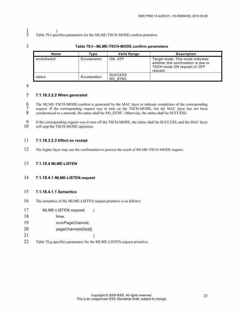
IEEE P802.15.4e/D0.01, (15-09/604/r6), 2010-03-08
Copyright © 2009 IEEE. All rights reserved. This is an unapproved IEEE Standards Draft, subject to change.
25
) 1 Table 78.f specifies parameters for the MLME-TSCH-MODE.confirm primitive. 2
Table 78.f—MLME-TSCH-MODE.confirm parameters 3 Name Type Valid Range Description
modeSwitch Enumeration ON, OFF Target mode. This mode indicates whether this confirmation is due to TSCH-mode ON request or OFF request.
status Enumeration SUCCESS NO_SYNC
4
7.1.18.3.2.2 When generated 5
The MLME-TSCH-MODE.confirm is generated by the MAC layer to indicate completion of the corresponding 6 request. If the corresponding request was to turn on the TSCH-MODE, but the MAC layer has not been 7 synchronized to a network, the status shall be NO_SYNC. Otherwise, the status shall be SUCCESS. 8
If the corresponding request was to turn off the TSCH-MODE, the status shall be SUCCESS, and the MAC layer 9 will stop the TSCH-MODE operation. 10
7.1.18.3.2.3 Effect on receipt 11
The higher layer may use the confirmation to process the result of MLME-TSCH-MODE.request. 12
7.1.18.4 MLME-LISTEN 13
7.1.18.4.1 MLME-LISTEN.request 14
7.1.18.4.1.1 Semantics 15
The semantics of the MLME-LISTEN.request primitive is as follows: 16
MLME-LISTEN.request ( 17 time, 18 numPageChannel, 19 pageChannelsDes[] 20 ) 21
Table 78.g specifies parameters for the MLME-LISTEN.request primitive. 22

2010-03-08, (15-09/604/r6), IEEE P802.15.4e/D0.01
Copyright © 2010 IEEE. All rights reserved. This is an unapproved IEEE Standards Draft, subject to change.
26
Table 78.g—MLME-LISTEN.request parameters 1 Name Type Valid Range Description
onTime Integer 0x0000 – 0xFFFF
The amount of time (10 ms units) to stay on each channel. 0x0000 indicates that the MAC stops listening
offTime Integer 0x0000 – 0xFFFF The amount of time (10 ms units) to wait between channel changes.
numPageChannel Integer 0x01-0xFF The number of page channel descriptors in the page channels array.
pageChannelsDes[] Table 78.h Table 78.h Array of page channel descriptor. See
Table 78.h for the format of page channel descriptor.
2 Table 78.h—MLME-LISTEN.request pageChannelDesc parameters 3
Name Type Valid Range Description
channelPageId
Integer Selected from the available channel pages supported by the PHY (see 6.1.2)
Channel page ID.
numChannel Integer 0x01-0xFF The number of channels in this channel page to be included in listening.
Channels[] Array of Channel Table 4.
The array of channels on which to listen. See Table 4 for the valid range of channels in each channel page.
4
7.1.18.4.1.2 When generated 5
The MLME-LISTEN.request shall be generated by the next higher layer to initiate the search for a TSCH-6 network. 7
7.1.18.4.1.3 Effect on receipt 8
Upon receipt of the request the MAC layer shall activate the radio on the indicated channel and wait for an 9 Advertisement command. The MAC shall listen on Channel[0] for onTime, inactivate the radio for offTime, then 10 repeat with Channels[1], etc. After listening to the last channel in Channels[], the MAC returns to Channel[0]. 11 Valid Advertisement command frames received in this state shall result in the generation of MLME-12 ADVERTISE.indication. All other frames shall be dropped. The MAC shall stay in the listening state until it 13 receives a MLML-LISTEN.request with an onTime of 0x0000, or a MLME-TSCH-MODE.request is received. 14 The higher layer selects the advertiser and the network before setting the slotframe, link(s), and TSCH-mode. 15 Advertisements will continue to be received, and passed on to the higher layer until leaving the listen state. 16
7.1.18.4.2 MLME-LISTEN.confirm 17
7.1.18.4.2.1 Semantics 18
The semantics of the MLME-LISTEN.confirm primitive is as follows: 19
MLME-LISTEN.confirm ( 20 status 21 ) 22

IEEE P802.15.4e/D0.01, (15-09/604/r6), 2010-03-08
Copyright © 2009 IEEE. All rights reserved. This is an unapproved IEEE Standards Draft, subject to change.
27
Table 78.i specifies parameters for the MLME-LISTEN.confirm primitive. 1
Table 78.i—MLME-LISTEN.confirm parameters 2 Name Type Valid Range Description
status Enumeration SUCCESS INVALID_PARAMETER
3
7.1.18.4.2.2 When generated 4
The MAC layer shall generate MLME-LISTEN.confirm when it completes the listen operation started by 5 MLME-LISTEN.request. If any of the fields of the MLME-LISTEN.request are not valid, the status of the 6 primitive shall indicate INVALID PARAMETER. 7
7.1.18.4.2.3 Effect on receipt 8
On receipt of the primitive, the higher layer may continue with its joining state machine. 9
7.1.18.5 MLME-ADVERTISE 10
7.1.18.5.1 MLME-ADVERTISE.request 11
7.1.18.5.1.1 Semantics 12
The semantics of the MLME-ADVERTISE.request primitive is as follows: 13
MLME-ADVERTISE.request ( 14 advertiseInterval, 15 channelPage, 16 channelMap, 17 hoppingSequenceId, 18 timeslotTemplateId, 19 securityLevel, 20 joinPriority, 21 numSlotframe, 22 slotframes[] 23 ) 24
Table 78.j specifies parameters for the MLME-ADVERTISE.request primitive. 25

2010-03-08, (15-09/604/r6), IEEE P802.15.4e/D0.01
Copyright © 2010 IEEE. All rights reserved. This is an unapproved IEEE Standards Draft, subject to change.
28
Table 78.j—MLME-ADVERTISE.request parameters 1 Name Type Valid Range Description
advertiseInterval Integer 0x0000 – 0xFFFF Interval specifying the transmission of
the Advertisement command (in 10 ms units)
channelPage Integer
Selected from the available channel pages supported by the PHY (see 6.1.2)
Channel page supported by PHY.
channelMap Bitmap Array of bits Map of channels to be included in the Advertisement command.
hoppingSequenceId Integer 0x0 – 0xF ID of hopping sequence used. timeslotTemplateId Integer 0x0 – 0xF ID of timeslot template used.
securityLevel Enumeration Table 136 Security level in the Advertisement command. See Table 136.
joinPriority Integer 0x00 – 0xFF Join priority to be indicated in the Advertisement command.
numSlotframe Integer 0x0 – 0xF Number of slotframes to be indicated in the Advertisement command.
Slotframes[] See Table 78.k See Table 78.k See Table 78.k.
2 3
Table 78.k—MLME-ADVERTISE.request Slotframe parameters (per slotframe) 4 Name Type Valid Range Description
slotframeId Integer 0x00 – 0xFF Slotframe ID.
5
7.1.18.5.1.2 When generated 6
The next higher layer requests the MAC layer to start sending Advertisement command frames using MLME-7 ADVERTISE.request so that new nodes can find the network and this device. 8
7.1.18.5.1.3 Effect on receipt 9
Upon receipt of the request the MAC layer shall send the Advertisement command frame on the first available 10 TX link. Whenever the time specified in AdvertiseInterval lapses from the previous transmission of 11 Advertisement command frame, the MAC layer shall repeat the Advertisement command frame on next TX link 12 available. The remaining parameters specify the slotframes to be included in the Advertisement command 13 frames. Links in the specified slotframes with an Advertising linkType are to be included in the Advertisement 14 command. 15
7.1.18.5.2 ADVERTISE.indication 16
The MLME-ADVERTISE.indication indicates that a device received an Advertisement command frame. 17
7.1.18.5.2.1 Semantics 18
The semantics of the MLME-ADVERTISE.indication primitive is as follows: 19
MLME-ADVERTISE.indication ( 20

IEEE P802.15.4e/D0.01, (15-09/604/r6), 2010-03-08
Copyright © 2009 IEEE. All rights reserved. This is an unapproved IEEE Standards Draft, subject to change.
29
PANId, 1 timingInformation, 2 channelPage, 3 channelMap, 4 hoppingSequenceId, 5 timeslotTemplateId, 6 securityLevel, 7 joinPriority, 8 linkQuality, 9 numSlotframes, 10 slotframes[] 11 ) 12
Table 78.l specifies parameters for the MLME-ADVERTISE.indication primitive. 13
Table 78.l—MLME-ADVERTISE.indication parameters 14 Name Type Valid Range Description
PANId Integer 0x0000 – 0xFFFF The PAN identifier indicated in the Advertisement command.
timingInformation The time information (absolute slot number) of the timeslot in which the Advertisement command was received.
channelPage
Integer Selected from the available channel pages supported by the PHY (see 6.1.2)
Channel page.
channelMap Bitmap Array of bits Bit map of channels. hoppingSequenceId Integer 0x0 – 0xF ID of hopping sequence used. timeslotTemplateId Integer 0x0 – 0xF ID of timeslot template used.
securityLevel Enumeration Table 136 Security level in advertisement packet See Table 136.
joinPriority Integer 0x00 – 0xFF Join priority indicated in advertisement.
linkQuality Integer 0x00 – 0xFF Link quality indicated in the frame by the PHY layer.
numSlotframes Integer 0x0 – 0xF Number of slotframes indicated in the Advertisement command received.
slotframes[] See Table 78.m See Table 78.m See Table 78.m. Slotframes and links are from received Advertisement command frame.
15 Table 78.m—MLME-ADVERTISE.indication parameters (per slotframe) 16
Name Type Valid Range Description slotframeId Integer 0x00 – 0xFF Slotframe ID. slotframeSize Integer 0x0000 – 0xFFFF Slotframe size.
numLink Integer 0x0 – 0xF Number of links for the specified slotframe
links Table 78.n Table 78.n Table 78.n for parameters (per link)
17

2010-03-08, (15-09/604/r6), IEEE P802.15.4e/D0.01
Copyright © 2010 IEEE. All rights reserved. This is an unapproved IEEE Standards Draft, subject to change.
30
Table 78.n—MLME-ADVERTISE.indication parameters (per link) 1 Name Type Valid Range Description
timeslot Integer 0x0000 – 0xFFFF Timeslot. chanOffset Integer 0x00 – 0xFF Channel offset. linkOption Enumeration TX
RX SHARED_TX
Option of the link.
timeslot Integer 0x0000 – 0xFFFF Timeslot.
2
7.1.18.5.2.2 When generated 3
The MLME-ADVERTISE.indication shall be generated when an Advertisement command frame has been 4 received by the device. Upon receiving a valid Advertisement command, the device shall be synchronized to the 5 network and ready to enable the TSCH-MODE if requested by the higher layer. 6
7.1.18.5.2.3 Effect on receipt 7
The higher layer may wait and record more than one advertisement and then select the desired advertising device 8 before configuring the superframe(s) and link(s) and before enabling TSCH-MODE. After joining a TSCH-9 network, the high layer uses the indication to collect the list of neighbors and information about neighbors. 10
7.1.18.5.3 MLME-ADVERTISE.confirm 11
7.1.18.5.3.1 Semantics 12
The semantics of the MLME-ADVERTISE.confirm primitive is as follows: 13
MLME-ADVERTISE.confirm ( 14 status 15 ) 16
Table 78.o specifies parameters for the MLME-ADVERTISE.confirm primitive. 17
Table 78.o—MLME-ADVERTISE.confirm parameters 18 Name Type Valid Range Description
Status Enumeration SUCCESS INVALID_PARAMETER
19
7.1.18.5.3.2 When generated 20
The MAC layer shall generate MLME-ADVERTISE.confirm when it starts sending the Advertisement 21 command. If the any of the fields of the MLME-ADVERTISE.request are not valid, the status of the primitive 22 shall indicate INVALID PARAMETER. 23

IEEE P802.15.4e/D0.01, (15-09/604/r6), 2010-03-08
Copyright © 2009 IEEE. All rights reserved. This is an unapproved IEEE Standards Draft, subject to change.
31
7.1.18.5.3.3 Effect on receipt 1
On receipt of the primitive, the higher layer may expect that it will receive the Join command on any of the links 2 provided in the Advertisement command. 3
7.1.18.6 MLME-KEEP-ALIVE 4
7.1.18.6.1 MLME-KEEP-ALIVE.request 5
7.1.18.6.1.1 Semantics 6
The semantics of the MLME-KEEP-ALIVE.request primitive is as follows: 7
MLME-KEEP-ALIVE.request ( 8 dstAddr, 9 period 10 ) 11
Table 78.p specifies parameters for the MLME-KEEP-ALIVE.request primitive. 12
Table 78.p—MLME-KEEP-ALIVE.request parameters 13 Name Type Valid Range Description
dstAddr Integer 0x0000 - 0xFFFF Address of neighbor device to maintain the timing. Keepalives with dstAddr of 0xFFFF do not expect to be acknowledged.
period Integer 0x0001 – 0xFFFF Duration of quiet time in seconds that a Keep-Alive command frame should be sent if no traffic is present.
14
7.1.18.6.1.2 When generated 15
7.1.18.6.1.3 Effect on receipt 16
Upon receipt of the request, the MAC layer shall monitor the frame sent to the destination node specified in the 17 dstAddr parameter. If no frame is sent to the destination node for any duration defined by the period parameter, 18 the MAC shall send an empty (no MAC payload) frame to the node dstAddr. The Sequence Number subfield of 19 the MHR of the frame shall be set to the least significant byte of the absolute slot number. Resolution between 20 the short form dstAddr and its long form address (8 octets) may be needed for security purposes. This is 21 determined by NHL. 22
7.1.18.6.2 MLME-KEEP-ALIVE.confirm 23
7.1.18.6.2.1 Semantics 24
The semantics of the MLME-KEEP-ALIVE.confirm primitive is as follows: 25
MLME-KEEP-ALIVE.confirm ( 26

2010-03-08, (15-09/604/r6), IEEE P802.15.4e/D0.01
Copyright © 2010 IEEE. All rights reserved. This is an unapproved IEEE Standards Draft, subject to change.
32
status 1 ) 2
Table 78.q specifies parameters for the MLME-KEEP-ALIVE.confirm primitive. 3 Table 78.q—MLME-KEEP-ALIVE.confirm parameters 4
Name Type Valid Range Description Status Enumeration SUCCESS
INVALID_PARAMETER
5
7.1.18.6.2.2 When generated 6
The MAC layer shall generate MLME-KEEP-ALIVE.confirm to acknowledge that it received MLME-KEEP-7 ALIVE request. If the dstAddr of the MLME-KEEP-ALIVE.request is not 0xFFFF and the dstAddr does not 8 exist in the devices neighbor table, the status of the primitive shall indicate INVALID PARAMETER. 9
7.1.18.6.2.3 Effect on receipt 10
None. 11
7.1.18.7 MLME-JOIN 12
7.1.18.7.1 MLME-JOIN.request 13
7.1.18.7.1.1 Semantics 14
The semantics of the MLME-JOIN.request primitive is as follows: 15
MLME-JOIN.request ( 16 dstAddr, 17 securityInformation, 18 numNeighbors, 19 neighbors[] 20 ) 21
Table 78.r specifies parameters for the MLME-JOIN.request primitive. 22
Table 78.r—MLME-JOIN.request parameters 23
24
Name Type Valid Range Description
dstAddr Integer 0x0000 - 0xFFFF Address of neighbor device to send Join command.
securityInformation Table 78.s Table 78.s See Table 78.s for the detail.
numNeighbors Integer 0x0 – 0xF Number of neighbors found by the joining device.
neighbors
Table 78.t Table 78.t Neighbor information for the number of neighbors specified in numNeighbors. See Table 78.t for the definition of a neighbor.

IEEE P802.15.4e/D0.01, (15-09/604/r6), 2010-03-08
Copyright © 2009 IEEE. All rights reserved. This is an unapproved IEEE Standards Draft, subject to change.
33
Table 78.s—MLME-JOIN.request securityInformation parameters 1
2 Table 78.t—MLME-JOIN.request neighbors parameters 3
4
7.1.18.7.1.2 When generated 5
Device management of a new device (or device who lost connection with the TSCH-network) will invoke this 6 service primitive to join the TSCH-network. 7
7.1.18.7.1.3 Effect on receipt 8
Upon receipt of the request, the MAC layer shall send either a Join command frame or data frame containing a 9 higher layer management packet requesting to join the network, using any link to the dstAddr. The content of the 10 Join command frame will be formatted using the other parameters and the format of Join command frame is 11 specified in 7.3.10.2.9. If a data frame with the higher layer management packet is used instead of a Join 12 command frame, the content of the higher layer payload of the data frame containing the request to join the 13 network is constructed using the other parameters. The explicit format of the higher layer payload is out of scope 14 of this document. Resolution between the short form dstAddr and its long form address (8 octets) may be needed 15 for security purposes. This is determined by NHL. 16
7.1.18.7.2 MLME-JOIN.indication 17
7.1.18.7.2.1 Semantics 18
The semantics of the MLME-JOIN.indication primitive is as follows: 19
MLME-JOIN.indication ( 20 newNodeAddr, 21 securityInformation, 22 numNeighbors, 23 neighbors[] 24 ) 25
Table 78.u specifies parameters for the MLME-JOIN.indication primitive. 26
Name Type Valid Range Description
TBD TBD TBD The securityInformation definition will be defined with Security sub-group.
Name Type Valid Range Description neighborId Integer 0x0000 – 0xFFFF 16 bit address of neighbor.
RSSI Integer -128 to 127 Received signal strength (in dBm) of frames received from the neighbor.

2010-03-08, (15-09/604/r6), IEEE P802.15.4e/D0.01
Copyright © 2010 IEEE. All rights reserved. This is an unapproved IEEE Standards Draft, subject to change.
34
Table 78.u—MLME-JOIN.indication parameters 1 Name Type Valid Range Description
newNodeAddr Array of octets
64-bit binary string 64-bit long address of new device sending the Join command.
securityInformation Table 78.s Table 78.s See Table 78.s.
numNeighbors Integer 0x0 – 0xF Number of neighbors reported by the joining device.
Neighbors
Table 78.t Table 78.t Neighbor information for the number of neighbors specified in numNeighbors. See Table 78.t for the definition of a neighbor in neighbors.
7.1.18.7.2.2 When generated 2
MLME-JOIN.indication indicates the Device Management layer that the MAC layer has received a Join 3 command frame from a new device attempting to join the TSCH-network. 4
7.1.18.7.2.3 Effect on receipt 5
Upon receipt of the MLME-JOIN.indication, the Device Management layer shall invoke the device management 6 procedure to transfer the join attempt of the new device to the Device Manager. 7
7.1.18.7.3 MLME-JOIN.confirm 8
7.1.18.7.3.1 Semantics 9
The semantics of the MLME-JOIN.confirm primitive is as follows: 10
MLME-JOIN.confirm ( 11 status 12 ) 13
Table 78.v specifies parameters for the MLME-JOIN.confirm primitive. 14
Table 78.v—MLME-JOIN.confirm parameters 15 Name Type Valid Range Description
Status Enumeration SUCCESS INVALID_PARAMETER
16
7.1.18.7.3.2 When generated 17
The MAC layer shall generate MLME-JOIN.confirm to acknowledge that it received the MLME-JOIN.request 18 primitive. If the any of the fields of the MLME-JOIN.request are not valid, the status of the primitive shall 19 indicate INVALID PARAMETER. 20
7.1.18.7.3.3 Effect on receipt 21
None 22

IEEE P802.15.4e/D0.01, (15-09/604/r6), 2010-03-08
Copyright © 2009 IEEE. All rights reserved. This is an unapproved IEEE Standards Draft, subject to change.
35
7.1.18.8 MLME-ACTIVATE 1
7.1.18.8.1 MLME-ACTIVATE.request 2
7.1.18.8.1.1 Semantics 3
The semantics of the MLME-ACTIVATE.request primitive is as follows: 4
MLME-ACTIVATE.request ( 5 dstAddr, 6 securityInformation, 7 slotframes[] 8 ) 9
Table 78.w and Table 78.y specify parameters for the MLME-ACTIVATE.request primitive. 10
Table 78.w—MLME-ACTIVATE.request parameters 11
12 Table 78.x—MLME-ACTIVATE.request securityInformation parameters 13
14 Table 78.y—MLME-ACTIVATE.request slotframe parameters (per slotframe) 15
16 Table 78.z—MLME-ACTIVATE.request Link parameters (per link) 17
18
Name Type Valid Range Description
dstAddr Integer 0x0000 - 0xFFFF Address of neighbor device to send Activate command.
securityInformation Table 78.x Table 78.x See Table 78.x for details. slotframes[] Table 78.k Table 78.k See Table 78.k.
Name Type Valid Range Description
TBD TBD TBD The securityInformation definition will be defined with the Security sub-group.
Name Type Valid Range Description slotframeId Integer 0x00 – 0xFF Slotframe ID. slotframeSize Integer 0x00 – 0xFFFF Slotframe size.
numLink Integer 0x0 – 0xF Number of links for the specified slotframe to be indicated in the Advertisement command.
links Table 78.z Table 78.z See Table 78.z for parameters (per link)
Name Type Valid Range Description timeslot Integer 0x0000 – 0xFFFF Timeslot. chanOffset Integer 0x00-0xnn nn = number of active channels in the
channel map for the slotframe used. linkOption Enumeration TX
RX SHARED_TX
Option of the link.
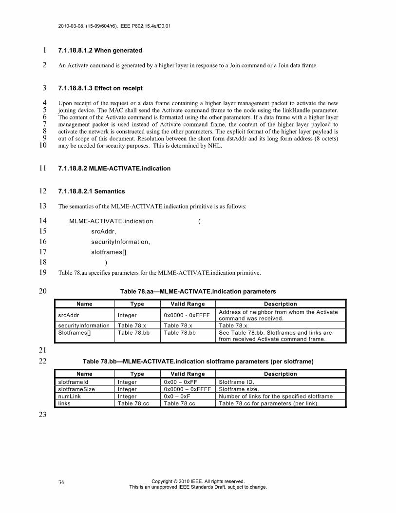
2010-03-08, (15-09/604/r6), IEEE P802.15.4e/D0.01
Copyright © 2010 IEEE. All rights reserved. This is an unapproved IEEE Standards Draft, subject to change.
36
7.1.18.8.1.2 When generated 1
An Activate command is generated by a higher layer in response to a Join command or a Join data frame. 2
7.1.18.8.1.3 Effect on receipt 3
Upon receipt of the request or a data frame containing a higher layer management packet to activate the new 4 joining device. The MAC shall send the Activate command frame to the node using the linkHandle parameter. 5 The content of the Activate command is formatted using the other parameters. If a data frame with a higher layer 6 management packet is used instead of Activate command frame, the content of the higher layer payload to 7 activate the network is constructed using the other parameters. The explicit format of the higher layer payload is 8 out of scope of this document. Resolution between the short form dstAddr and its long form address (8 octets) 9 may be needed for security purposes. This is determined by NHL. 10
7.1.18.8.2 MLME-ACTIVATE.indication 11
7.1.18.8.2.1 Semantics 12
The semantics of the MLME-ACTIVATE.indication primitive is as follows: 13
MLME-ACTIVATE.indication ( 14 srcAddr, 15 securityInformation, 16 slotframes[] 17 ) 18
Table 78.aa specifies parameters for the MLME-ACTIVATE.indication primitive. 19
Table 78.aa—MLME-ACTIVATE.indication parameters 20
21 Table 78.bb—MLME-ACTIVATE.indication slotframe parameters (per slotframe) 22
23
Name Type Valid Range Description
srcAddr Integer 0x0000 - 0xFFFF Address of neighbor from whom the Activate command was received.
securityInformation Table 78.x Table 78.x Table 78.x. Slotframes[] Table 78.bb Table 78.bb See Table 78.bb. Slotframes and links are
from received Activate command frame.
Name Type Valid Range Description slotframeId Integer 0x00 – 0xFF Slotframe ID. slotframeSize Integer 0x0000 – 0xFFFF Slotframe size. numLink Integer 0x0 – 0xF Number of links for the specified slotframe links Table 78.cc Table 78.cc Table 78.cc for parameters (per link).

IEEE P802.15.4e/D0.01, (15-09/604/r6), 2010-03-08
Copyright © 2009 IEEE. All rights reserved. This is an unapproved IEEE Standards Draft, subject to change.
37
Table 78.cc—MLME-ACTIVATE.indication Link parameters (per link) 1
2 3
7.1.18.8.2.2 When generated 4
MLME-ACTIVATE.indication indicates the device management layer that the MAC layer has received an 5 Activate command frame from the neighbor indentified in srcAddr. 6
7.1.18.8.2.3 Effect on receipt 7
Upon receipt of the MLME-ACTIVATE.indication, the device management layer shall process the 8 securityInformation received to set up secure connections. The device management layer should use the 9 information in the MLME-ACTIVATE.indication to add slotframes and links using the MLME-SET-10 SLOTFRAME.request and MLME-SET-LINK.request primitives. The device management layer should delete 11 slotframes and links obtained from previous advertisements if not explicitly added in the activate command 12 frame. Resolution between the short form srcAddr and its long form address (8 octets) may be needed for 13 security purposes. This is determined by NHL. 14
7.1.18.8.3 MLME-ACTIVATE.confirm 15
7.1.18.8.3.1 Semantics 16
The semantics of the MLME-ACTIVATE.confirm primitive is as follows: 17
MLME-ACTIVATE.confirm ( 18 status 19 ) 20
Table 78.dd specifies parameters for the MLME-ACTIVATE.confirm primitive. 21
Table 78.dd—MLME-ACTIVATE.confirm parameters 22
23
7.1.18.8.3.2 When generated 24
The MAC layer shall generate MLME-ACTIVATE.confirm to acknowledge that it received MLME-25 ACTIVATE.request. If any of the fields of the MLME-ACTIVATE.request are not valid, the status of the 26 primitive shall indicate INVALID PARAMETER. 27
Name Type Valid Range Description timeslot Integer 0x0000 – 0xFFFF Timeslot. chanOffset Integer 0x00 – 0xFF Channel offset. linkOption Enumeration TX
RX SHARED_TX
Option of the link.
Name Type Valid Range Description Status Enumeration SUCCESS
INVALID_PARAMETER

2010-03-08, (15-09/604/r6), IEEE P802.15.4e/D0.01
Copyright © 2010 IEEE. All rights reserved. This is an unapproved IEEE Standards Draft, subject to change.
38
7.1.18.8.3.3 Effect on receipt 1
2
7.1.18.9 MLME-DISASSOCIATE 3
7.1.18.9.1 MLME-DISASSOCIATE.request 4
7.1.18.9.1.1 Semantics 5
The semantics of the MLME-DISASSOCIATE.request primitive is as follows: 6
MLME-DISASSOCIATE.request ( 7 ) 8
7.1.18.9.1.2 When generated 9
MLME-DISASSOCIATE.request primitive is used to initiate the graceful disassociation from TSCH-network. 10
7.1.18.9.1.3 Effect on receipt 11
Upon receipt of the request, the MAC layer shall send a disassociation notification command frame or a data 12 frame containing a higher layer management packet to indicate that it is about to leave the TSCH-network on all 13 unicast transmit links. The Sequence Number subfield of the MHR of the frame shall be set to the least 14 significant byte of the absolute slot number. 15
After the MAC sends the disassociation notification command frame for macDisconnectTime, it shall release all 16 slotframe and link resources. 17
7.1.18.9.2 MLME-DISASSOCIATE.indication 18
7.1.18.9.2.1 Semantics 19
The semantics of the MLME-DISASSOCIATE.indication primitive is as follows: 20
MLME-DISASSOCIATE.indication ( 21 srcAddress, 22 ) 23
Table 78.ee specifies parameters for the MLME-DISASSOCIATE.indication primitive. 24
Table 78.ee—MLME-DISASSOCIATE.indication parameters 25 Name Type Valid Range Description
srcAddr Integer 0x0000 – 0xFFFF 16-bit short address of the neighbor node from which the DISASSOCIATE command frame was received.
26

IEEE P802.15.4e/D0.01, (15-09/604/r6), 2010-03-08
Copyright © 2009 IEEE. All rights reserved. This is an unapproved IEEE Standards Draft, subject to change.
39
7.1.18.9.2.2 When generated 1
MLME-DISASSOCIATE.indication indicates to the device management layer that the MAC layer has received a 2 Disassociate command frame from a neighbor node, the address of which is indicated by srcAddress. 3
7.1.18.9.2.3 Effect on receipt 4
Upon receipt of the MLME-DISASSOCIATE.indication, the device management layer shall process the 5 disassociation of the neighbor from which the Disassociate command frame is received. Resolution between the 6 short form srcAddr and its long form address (8 octets) may be needed for security purposes. This is determined 7 by NHL. 8
A device should only leave the TSCH network if it receives a disassociate command frame from either the PAN 9 coordinator or all of its clock source neighbors. This command should only be accepted when addressed directly 10 to the device using appropriate peer level security. 11
7.1.18.9.3 MLME-DISASSOCIATE.confirm 12
7.1.18.9.3.1 Semantics 13
The semantics of the MLME-DISASSOCIATE.confirm primitive is as follows: 14
MLME-DISASSOCIATE.confirm ( 15 status 16 ) 17
Table 78.ff specifies parameters for the MLME-DISASSOCIATE.confirm primitive. 18
Table 78.ff—MLME-DISASSOCIATE.confirm parameters 19 Name Type Valid Range Description
Status Enumeration SUCCESS
20
7.1.18.9.3.2 When generated 21
The MAC layer shall generate MLME-DISASSOCIATE.confirm to acknowledge that it received MLME-22 DISASSOCIATE request. 23
7.1.18.9.3.3 Effect on receipt 24
None. 25
7.1.19 LL-specific MAC sublayer service specification 26
27

2010-03-08, (15-09/604/r6), IEEE P802.15.4e/D0.01
Copyright © 2010 IEEE. All rights reserved. This is an unapproved IEEE Standards Draft, subject to change.
40
7.1.19.1 Primitives for Superframe Configuration of low latency networks 1
7.1.19.1.1 General 2
These primitives control the different modes for the configuration and operation of the superframe in a low 3 latency network. 4
7.1.19.1.2 MLME-LL_NW.discovery 5
7.1.19.1.2.1 General 6
This primitive switches the LL-network into discover mode. 7
7.1.19.1.2.2 Semantics of the Service Primitive 8
The semantics of the MLME-LL_NW.discovery primitive is as follows: 9
10 MLME-LL_NW.discovery ( 11
LowLatencyNetworkConfiguration 12 ) 13
Table 78.gg specifies the parameters for the MLME-LL_NW.discovery primitive. 14
Table 78.gg—MLME-LL_NW.discovery parameters 15 Name Type Valid Range Description
LowLatencyNetworkConfiguration
Object Contains the necessary configuration parameters for the low latency network in discovery mode
16
7.1.19.1.2.3 Appropriate usage 17
The MLME-LLNW.discovery primitive is generated by the next higher layer of an LLNW coordinator and 18 issued to its MLME to switch the low latency network into Discovery mode (7.3.27.2). 19
7.1.19.1.2.4 Effect on receipt 20
When the MLME of an LLNW coordinator receives the MLME-LLNW.discovery primitive, it sets the 21 Transmission Mode subfield in the Flags field of the payload of the 1-octet MHR Beacons to the value for 22 Discovery Mode as indicated in Table 122.b(Transmission Mode settings) and follows the procedures as 23 defined for Discovery Mode in 7.3.27.2. 24

IEEE P802.15.4e/D0.01, (15-09/604/r6), 2010-03-08
Copyright © 2009 IEEE. All rights reserved. This is an unapproved IEEE Standards Draft, subject to change.
41
7.1.19.1.3 MLME-LL_NW.discovery_confirm 1
7.1.19.1.3.1 General 2
This primitive indicates the end of the discover mode and gives the status of the discover mode to the next higher 3 layer. 4
7.1.19.1.3.2 Semantics of the Service Primitive 5
The semantics of the MLME-LL_NW.discovery_confirm primitive is as follows: 6
MLME-LL_NW.discovery_confirm ( 7 LowLatencyNetworkConfiguration 8 DiscoveryModeStatus 9 ) 10
Table 78.hh specifies the parameters for the MLME-LL_NW.discovery_confirm primitive. 11 12 13 14
Table 78.hh—MLME-LLNW.discovery_confirm parameters 15 Name Type Valid Range Description
LowLatencyNetworkConfiguration
Object Contains the necessary configuration parameters for the low latency network in discovery mode
DiscoveryModeStatus
Object Contains the collected information about discovered devices in the low latency network
16
7.1.19.1.3.3 When generated 17
The MLME-LLNW.discovery_confirm primitive is generated by the MLME of the LLNW coordinator and 18 issued to its next higher layer to indicate the end of the discovery mode in the low latency network. It 19 returns the collected information about the discovered devices in the low latency network to the higher 20 layer. 21
7.1.19.1.3.4 Appropriate usage 22
When the next higher layer of an LLNW coordinator receives the MLME-LLNW.discovery_confirm 23 primitive, the LLNW coordinator determines a configuration of the low latency network based on the 24 information about the discovery devices received in DiscoveryModeStatus. It uses an algorithm outside the 25 scope of this standard. The next higher layer of the LLNW coordinator then issues the MLME-26 LLNW.configuration primitive to its MLME. 27

2010-03-08, (15-09/604/r6), IEEE P802.15.4e/D0.01
Copyright © 2010 IEEE. All rights reserved. This is an unapproved IEEE Standards Draft, subject to change.
42
7.1.19.1.4 MLME-LL_NW.configuration 1
7.1.19.1.4.1 General 2
This primitive switches the LL-network into configuration mode. 3
7.1.19.1.4.2 Semantics of the Service Primitive 4
The semantics of the MLME-LL_NW.configuration primitive is as follows: 5
6 MLME-LL_NW.configuration ( 7
LowLatencyNetworkConfiguration 8 ) 9
Table 78.ii specifies the parameters for the MLME-LL_NW.configuration primitive. 10
Table 78.ii—MLME-LLNW.configuration parameters 11 Name Type Valid Range Description
LowLatencyNetworkConfiguration
Object Contains the necessary configuration parameters for the low latency network in configuration mode
12
7.1.19.1.4.3 Appropriate usage 13
The MLME-LLNW.configuration primitive is generated by the next higher layer of an LLNW coordinator 14 and issued to its MLME to switch the low latency network into Configuration mode (7.3.27.3). 15
7.1.19.1.4.4 Effect on receipt 16
When the MLME of an LLNW coordinator receives the MLME-LLNW.configuration primitive, it sets the 17 Transmission Mode subfield in the Flags field of the payload of the 1-octet MHR Beacons to the value for 18 Configuration Mode as indicated in Table 122.b (Transmission Mode settings) and follows the procedures 19 as defined for Configuration Mode in 7.3.27.3. 20
7.1.19.1.5 MLME-LL_NW.configuration_confirm 21
7.1.19.1.5.1 General 22
This primitive indicates the end of the configuration mode and gives the status of the configuration mode to the 23 next higher layer. 24
7.1.19.1.5.2 Semantics of the Service Primitive 25
The semantics of the MLME-LL_NW.configuration_confirm primitive is as follows: 26
MLME-LL_NW.configuration_confirm ( 27

IEEE P802.15.4e/D0.01, (15-09/604/r6), 2010-03-08
Copyright © 2009 IEEE. All rights reserved. This is an unapproved IEEE Standards Draft, subject to change.
43
LowLatencyNetworkConfiguration 1 ConfigurationModeStatus 2 ) 3
Table 78.jj specifies the parameters for the MLME-LL_NW.configuration_confirm primitive. 4
Table 78.jj—MLME-LLNW.configuration_confirm parameters 5 Name Type Valid Range Description
LowLatencyNetworkConfiguration
Object Contains the necessary configuration parameters for the low latency network in configuration mode
ConfigurationModeStatus
Object Contains the return status of the configuration of the discovered devices in the low latency network
6
7.1.19.1.5.3 When generated 7
The MLME-LLNW.configuration_confirm primitive is generated by the MLME of the LLNW coordinator 8 and issued to its next higher layer to indicate the end of the configuration mode in the low latency network. 9 It returns the configuration status about the discovered devices in the low latency network to the higher 10 layer. 11
7.1.19.1.5.4 Appropriate usage 12
When the next higher layer of an LLNW coordinator receives the MLME-LLNW.confirmation_confirm 13 primitive, the next higher layer of the LLNW coordinator issues the MLME-LLNW.online, the MLME-14 LLNW.configuration, or the MLME-LLNW.discovery primitive to its MLME based on the value of 15 ConfigurationModeStatus. 16
7.1.19.1.6 MLME-LL_NW.online 17
7.1.19.1.6.1 General 18
This primitive switches the LL-network into online mode. 19
7.1.19.1.6.2 Semantics of the Service Primitive 20
The semantics of the MLME-LL_NW.online primitive is as follows: 21
MLME-LL_NW.online ( 22 ) 23
Table 78.kk specifies the parameters for the MLME-LL_NW.online primitive. 24

2010-03-08, (15-09/604/r6), IEEE P802.15.4e/D0.01
Copyright © 2010 IEEE. All rights reserved. This is an unapproved IEEE Standards Draft, subject to change.
44
Table 78.kk—MLME-LLNW.online parameters 1 Name Type Valid Range Description
none
2
7.1.19.1.6.3 Appropriate usage 3
The MLME-LLNW.online primitive is generated by the next higher layer of an LLNW coordinator and 4 issued to its MLME to switch the low latency network into Online mode (7.3.27.4). 5
7.1.19.1.6.4 Effect on receipt 6
When the MLME of an LLNW coordinator receives the MLME-LLNW.online primitive, it sets the 7 Transmission Mode subfield in the Flags field of the payload of the 1-octet MHR Beacons to the value for 8 Online Mode as indicated in Table 122.b (Transmission Mode settings) and follows the procedures as 9 defined for Online Mode in 7.3.27.4. 10
7.1.19.1.7 MLME-LL_NW.online_indication 11
7.1.19.1.7.1 General 12
This primitive indicates any problems during the online mode to the next higher layer. 13
7.1.19.1.7.2 Semantics of the Service Primitive 14
The semantics of the MLME-LL_NW.online_indication primitive is as follows: 15
MLME-LL_NW.online_indication ( 16 OnlineModeStatus 17 ) 18
Table 78.ll specifies the parameters for the MLME-LL_NW.online_indication primitive. 19
Table 78.ll—MLME-LLNW.online_indication parameters 20 Name Type Valid Range Description
OnlineModeStatus Object Contains the statusin the low latency network including any discovered problems.
21
7.1.19.1.7.3 When generated 22
The MLME-LLNW.online_indication primitive is generated by the MLME of any LLNW device and 23 issued to its next higher layer to indicate the status and any problems that occurred in the low latency 24 network during the operation in online mode. It returns the indication of the problem and the additional 25 supporting information to the higher layer. 26

IEEE P802.15.4e/D0.01, (15-09/604/r6), 2010-03-08
Copyright © 2009 IEEE. All rights reserved. This is an unapproved IEEE Standards Draft, subject to change.
45
7.1.19.1.7.4 Appropriate usage 1
When the next higher layer of an LLNW device receives the MLME-LLNW.online_indication primitive, 2 the LLNW device determines appropriate countermeasures using an algorithm outside the scope of this 3 standard. 4
7.1.20 DSME-specific MAC sublayer service specification 5
7.1.20.1 MLME-DSME 6
7.1.20.1.1 General 7
These DSME management primitives are optional and extent the MLME-SAP GTS management primitives 8 specified in 7.1.7. A device wishing to use these DSME primitives and GTSs in general will already be tracking 9 the beacons of its PAN coordinator. 10
7.1.20.1.2 MLME-DSME.request 11
7.1.20.1.2.1 General 12
The MLME-GTS.request (see 7.1.7.1) and MLME-DSME.request primitive allow a device to send a request to 13 the PAN coordinator to allocate a new GTS slot or to the Destination device to allocate a new GTS or DSME 14 slot. This primitive is also used to deallocate GTS or DSME. 15
If the value of the DSMEFlag in this primitive is set to ‘1’, the MLME-GTS.request primitive allows a Source 16 device to send a request to a Destination device to allocate a new DSME, or to deallocate / reallocate / change an 17 existing DSME. This primitive is also used by a Destination device to initiate an DSME deallocation, 18 reallocation, or change (reduce or restart). 19
7.1.20.1.2.2 Semantics 20
The semantics of the MLME- DSME.request primitive is as follows: 21
MLME-DSME.request ( 22 GTSCharacteristics, 23 SecurityLevel, 24 KeyIdMode, 25 KeySource, 26 KeyIndex, 27 DSMECharacteristics, 28 DSMEFlag 29 ) 30
Table 78.mm specifies the parameters for the MLME-DSME.request primitive. 31

2010-03-08, (15-09/604/r6), IEEE P802.15.4e/D0.01
Copyright © 2010 IEEE. All rights reserved. This is an unapproved IEEE Standards Draft, subject to change.
46
Table 78.mm— MLME-DSME.request parameters 1 Name Type Valid Range Description
GTSCharacteristics, Table 94 Table 94 See Table 94 SecurityLevel, Table 94 Table 94 See Table 94 KeyIdMode, Table 94 Table 94 See Table 94 KeySource, Table 94 Table 94 See Table 94 KeyIndex Table 94 Table 94 See Table 94 DSMEFlag Boolean TRUE or FALSE If this value is FALSE, the operation of this
primitive is the same way defined in 7.1.7.1. If this value is TRUE, the operation of this primitive is for the DSME mode specified in 7.1.20.1.2.
DSMECharacteristics DSMECharacteristics
See 7.3.10.2 The characteristics of the DSME request, including whether the request is for the allocation of a new DSME or the deallocation / reallocation / change of an existing GTS.
2
7.1.20.1.2.3 When generated 3
The MLME-DSME.request primitive can also be generated by the next higher layer of a Source device and 4 issued to its MLME to request the allocation of a new DSME or to request the deallocation / reallocation / 5 change of an existing DSME. It is also generated by the next higher layer of the Destination device and issued to 6 its MLME to request the deallocation, reallocation, or change of an existing DSME. 7
7.1.20.1.2.4 Effect on receipt 8
If the value of the DSMEFlag in this primitive equals to ‘0’, the effect of MLME-DSME.request is the same as it 9 is described in 7.1.7.1. If the value of the DSMEFlag is set to ‘1’, the effect of MLME-DSME.request is as 10 follows. 11
On receipt of the MLME-DSME.request primitive for DSME allocation, the MLME of the Source device 12 attempts to generate an DSME handshake command frame(see 7.3.10.2) with the Characteristics Type subfield 13 of the DSME Characteristics field set to one (DSME allocation), the DSME Handshake Type subfield set to zero 14 (DSME request). Then the MLME of the Source device will send it to the Destination device. 15
If macShortAddress is equal to 0xfffe or 0xffff, the Source device is not permitted to request an DSME 16 allocation. In this case, the MLME issues the MLME-DSME.confirm primitive containing a status of 17 NO_SHORT_ADDRESS. 18
If the SecurityLevel parameter is set to a valid value other than 0x00, indicating that security is required for this 19 frame, the MLME will set the Security Enabled subfield of the Frame Control field to one. The MAC sublayer 20 will perform outgoing processing on the frame based on the DstAddress, SecurityLevel, KeyIdMode, KeySource, 21 and KeyIndex parameters, as described in 7.5.8.2.1. If any error occurs during outgoing frame processing, the 22 MLME will discard the frame and issue the MLME-GTS.confirm primitive with the error status returned by 23 outgoing frame processing. 24
If the DSME handshake request command frame cannot be sent due to the channel condition, the MLME will 25 issue the MLME-DSME.confirm primitive with a status of CHANNEL_ACCESS_FAILURE. 26
If the MLME successfully transmits an DSME handshake command, the MLME will expect an acknowledgment 27 in return. If an acknowledgment is not received, the MLME will issue the MLME-GTS.confirm primitive with a 28 status of NO_ACK (see 7.5.6.4). 29

IEEE P802.15.4e/D0.01, (15-09/604/r6), 2010-03-08
Copyright © 2009 IEEE. All rights reserved. This is an unapproved IEEE Standards Draft, subject to change.
47
If the DSME request command frame is being sent (see 7.5.10.1), the source device will wait for at most an 1 DSMERequestWaitingTime symbols, if no DSME handshake reply command frame from the destination device 2 appears within this time, the MLME of the source device shall notify the next higher layer of the failure by the 3 MLME-DSME.confirm primitive with a status of NO_DATA. 4
On receipt of an DSME handshake command frame indicating an DSME allocation request, the Destination 5 device shall first check if there is available capacity in the current multi-superframe. When the Destination 6 device determines whether capacity is available for the requested DSME, it shall generate an DSME descriptor 7 (see 7.3.10.2) with the requested specifications and the 16-bit short address of the requesting source device. 8
If the MLME of the Destination device can allocate the requested DSME, it will set the DSME Slot Identifier 9 subfield in the DSME descriptor to the multi-superframe slot at which the allocated DSME begins from, the 10 length in the DSME descriptor to the length of the DSME and the Device short address to the address of the 11 source device. In addition, the destination device shall issue the MLME-DSME.indication primitive with the 12 characteristics of the allocated DSME and the DSMEFlag set to TRUE to notify the next higher layer of the 13 newly allocated DSME. If the MLME of the Destination device cannot allocate the requested DSME, the DSME 14 Slot Identifier shall be set to zero and the DSME length set to the largest DSME length that can currently be 15 supported. 16
The Destination device shall then include the DSME descriptor in its DSME handshake command frame and 17 broadcast it to its one-hop neighbors. The Characteristics Type subfield of the DSME Characteristics field shall 18 be set to one (DSME allocation) and the Handshake Type subfield shall be set to one (DSME reply). 19
On receipt of the DSME handshake command frame indicating an DSME allocation reply, the device shall 20 process the DSME descriptor. 21
If the address in the Device Short Address subfield of the DSME descriptor does not correspond to 22 macShortAddress of the device, the device updates its ABT to reflect the neighbor’s newly allocated DSME. If 23 the newly allocated DSME is conflicting with the device’s known DSME, the device shall send an DSME 24 handshake command frame to the origin device of the DSME handshake reply command frame. The 25 Characteristics Type subfield of the DSME Characteristics field set to three (DSME duplicate allocation 26 notification) and the Handshake Type subfield set to two (DSME notify), with the DSME Slot Identifier subfield 27 in the DSME descriptor set to the multi-superframe slot at which the DSME duplicate allocated, the length in the 28 DSME descriptor to the length of the duplicate allocated DSME and the Device short address to the address of 29 the device for which the DSME allocation replied. 30
If the address in the Device Short Address subfield of the DSME descriptor corresponds to macShortAddress of 31 the device, the MLME of the device shall then notify the next higher layer of whether the DSME allocation 32 request was successful by the primitive MLME-GTS.confirm, with a status of SUCCESS (if the DSME Slot 33 Identifier in the DSME descriptor was greater than zero) or DENIED(if the DSME Slot Identifier in the DSME 34 descriptor was equal to zero or if the length did not match the requested length). 35
After that, the Source device shall broadcast an DSME handshake command frame to all its one-hop neighbors. 36 The Characteristics Type subfield of the DSME Characteristics field shall be set to one (DSME allocation) and 37 the Handshake Type subfield shall be set to two (DSME notify). 38
On receipt of an DSME handshake command frame indicating an DSME allocation notify, the device shall 39 process the DSME descriptor. The device updates its ABT to reflect the neighbor’s newly allocated DSME. If the 40 newly allocated DSME conflicts with the device’s known DSME, the device shall send an DSME handshake 41 command frame to the origin device of the DSME handshake notify command frame. The Characteristics Type 42 subfield of the DSME Characteristics field shall be set to three (DSME duplicate allocation notification) and the 43 Handshake Type subfield shall be set to two (DSME notify), with the Device short address to the address of the 44 device which sent the DSME allocation notify. 45
On receipt of an DSME handshake command frame indicating an DSME duplicate allocation notification, the 46 MLME shall notify the next higher layer of the conflicts by the MLME-GTS.indication primitive with the 47 DSMEFlag set to TRUE, the Characteristics Type subfield set to three and the DSMECharacteristics set to the 48 characteristics of the duplicate allocation DSME. 49
2010-03-08, (15-09/604/r6), IEEE P802.15.4e/D0.01
Copyright © 2010 IEEE. All rights reserved. This is an unapproved IEEE Standards Draft, subject to change.
48
If the DSME request is to deallocate an existing DSME (see 7.5.7.4), on receipt of the MLME-DSME.request 1 primitive, the MLME shall send the DSME handshake command (see 7.3.10) to the corresponding device (the 2 Source or Destination of which the DSME to be deallocated), with the Characteristics Type subfield of the 3 DSME Characteristics field set to zero (DSME deallocation), the Handshake Type subfield shall be set to zero 4 (DSME request), and the DSME Length of the DSMEDescriptor subfields shall be set according to the 5 characteristics of the DSME to deallocate. 6
On receipt of an DSME handshake command frame indicating an DSME deallocation request, the device shall 7 attempt to deallocate the DSME. 8
If the DSME characteristics contained in the command do not match the characteristics of a known DSME, the 9 device shall ignore the request. 10
If the DSME characteristics contained in the DSME request command match the characteristics of a known 11 DSME, the MLME of the device shall deallocate the specified DSME, update its ABT and notify the next higher 12 layer of the change by the primitive MLME-GTS.indication with the DSMEFlag set to TRUE, the DSME 13 Characteristics parameter containing the characteristics of the deallocated DSME and the Characteristics Type 14 subfield set to zero (DSME deallocation). 15
Then, the device shall broadcast an DSME handshake command to its one-hop neighbors. The Characteristics 16 Type subfield of the DSME Characteristics field of the DSME handshake command shall be set to zero (DSME 17 deallocation), and the Handshake Type subfield shall be set to one (DSME reply). 18
On receipt of an DSME handshake command indicating an DSME deallocation reply, the device shall process 19 the DSME descriptor. If the address in the Device Short Address subfield of the DSME descriptor does not 20 correspond to macShortAddress of the device, the device updates its ABT to reflect all the neighbor’s deallocated 21 DSME. If the address in the Device Short Address subfield of the DSME descriptor corresponds to 22 macShortAddress of the device, the MLME of the device shall then notify the next higher layer of whether the 23 DSME deallocation request was successful by the primitive MLME-GTS.confirm primitive with a status of 24 SUCCESS (if the length in the DSME descriptor matched the requested deallocation length) or DENIED (if the 25 length in the DSME descriptor did not match the requested deallocation length). 26
Then, the device shall broadcast an DSME handshake command to all its one-hop neighbors. The Characteristics 27 Type subfield of the DSME Characteristics field shall be set to zero (DSME deallocation) and the Handshake 28 Type subfield shall be set to two (Notify). 29
On receipt of an DSME handshake command indicating an DSME deallocation notify, the device shall process 30 the DSME descriptor and update its ABT to reflect the neighbor’s deallocated DSME. 31
If Destination device request to change an allocated DSME of the Source device and the request has been 32 acknowledged by the Source device, the Destination device will issue the MLME-GTS.confirm primitive with a 33 status of SUCCESS, the DSMEFlag set to TRUE, the DSMECharacteristics Type subfield of the 34 DSMECharacteristics parameter set to 101 for DSME reduce or 110 for DSME restart accordingly, and other 35 subfields set according to the characteristics of the DSME which the Destination device requests the Source 36 device to change its original DSME to. 37
On receipt of an DSME handshake request command for DSME change from the destination device, the Source 38 device will acknowledge the frame and immediately change the DSME. Then the MLME of the Source device 39 will issue the MLME-GTS.indication primitive with an DSMECharacteristics parameter set according to the 40 characteristics of the DSME which the Destination device requests the Source device to change its original 41 DSME to. 42
If any parameter in the MLME-DSME.request primitive is not supported or is out of range, the MLME will issue 43 the MLME-GTS.confirm primitive with a status of INVALID_PARAMETER. 44
When DSMEFlag is TRUE, two types of channel diversity, channel adaptation and channel hopping, can be 45 employed to allocate DSME slots. Both channel diversity modes allocate DSME slots via DSME handshake 46 command. To exchange channel and DSME slot usage between devices, channel adaptation uses DSME 47

IEEE P802.15.4e/D0.01, (15-09/604/r6), 2010-03-08
Copyright © 2009 IEEE. All rights reserved. This is an unapproved IEEE Standards Draft, subject to change.
49
allocation bitmap table (ABT), while channel hopping uses DSME timeslot allocation bitmap (TAB). Detailed 1 procedures for allocating and deallocating DSME slots in two channel diversity modes are explained in 7.5.10.1 2 and 7.5.10.7. 3
7.1.20.1.3 MLME-DSME.confirm 4
7.1.20.1.3.1 General 5
If the value of the DSMEFlag equals to ‘1’, the MLME-DSME.confirm primitive reports the results of a request 6 to allocate a new DSME or to deallocate / reallocate / change an existing GTS. 7
7.1.20.1.3.2 Semantics 8
The semantics of the MLME-DSME.confirm primitive is as follows: 9
MLME-GTS.confirm ( 10 GTSCharacteristics, 11 status, 12 DSMEFlag, 13 DSMECharacteristics 14 ) 15
Table 78.nn specifies the parameters for the MLME-DSME.request primitive. 16
Table 78.nn— MLME-DSME.confirm parameters 17 Name Type Valid Range Description
GTSCharacteristics, Table 94 Table 94 See Table 94 status Table 94 Table 94 See Table 94 DSMEFlag Boolean TRUE or FALSE If this value is FALSE, the operation of this
primitive is the same way defined in 7.1.7.1. If this value is TRUE, the operation of this primitive is for the DSME mode specified in 7.1.20.1.2.
DSMECharacteristics DSMECharacteristics
See 7.3.10.2 The characteristics of the DSME confirm, including whether the confirm is for the allocation of a new DSME or the deallocation / reallocation / change of an existing GTS.
18
7.1.20.1.3.3 When generated 19
If the request to allocate, deallocate, reallocate, or change (reduce or restart) an DSME was successful, this 20 primitive will return a status of SUCCESS with the DSMEFlag set to ‘1’ and the DSMECharacteristics Type 21 subfield of the DSMECharacteristics parameter set accordingly. Otherwise, the status parameter will indicate the 22 appropriate error code. The reasons for these status values are fully described in 7.1.7.1.3 and subclauses 23 referenced by 7.1.7.1.3. 24

2010-03-08, (15-09/604/r6), IEEE P802.15.4e/D0.01
Copyright © 2010 IEEE. All rights reserved. This is an unapproved IEEE Standards Draft, subject to change.
50
7.1.20.1.3.4 Effect on receipt 1
On receipt of the MLME-GTS.confirm primitive with the value of the DSMEFlag set to ‘1’, the next higher layer 2 is notified of the result of its request to allocate, deallocate, or change an DSME. If the request was successful, 3 the status parameter will indicate a successful DSME operation, and the MLME of the device will generate an 4 DSME handshake command frame with the Handshake Type subfield set to two (DSME notify) and the 5 information contained in the DSMECharacteristics parameter in this primitive. Otherwise, the status parameter 6 will indicate the error. 7
7.1.20.1.4 MLME-DSME.indication 8
7.1.20.1.4.1 General 9
If the value of the DSMEFlag equals to ‘1’, the MLME-DSME.indication primitive reports the results of a 10 request to allocate a new DSME or to deallocate / reallocate / change an existing GTS. 11
7.1.20.1.4.2 Semantics 12
The semantics of the MLME-DSME.indication primitive is as follows: 13
MLME-GTS.indication ( 14 DeviceAddress, 15 GTSCharacteristics, 16 SecurityLevel, 17 KeyIdMode, 18 KeySource, 19 KeyIndex, 20 DSMEFlag, 21 DSMECharacteristics 22 ) 23
Table 78.nn specifies the parameters for the MLME-DSME.request primitive. 24
Table 78.oo— MLME-DSME.indication parameters 25 Name Type Valid Range Description
GTSCharacteristics, Table 94 Table 94 See Table 94 status Table 94 Table 94 See Table 94 DSMEFlag Boolean TRUE or FALSE If this value is FALSE, the operation of this
primitive is the same way defined in 7.1.7.1. If this value is TRUE, the operation of this primitive is for the DSME mode specified in 7.1.20.1.2.
DSMECharacteristics DSMECharacteristics
See 7.3.10.2 The characteristics of the DSME indication, including whether the indication is for the allocation of a new DSME or the deallocation / reallocation / change of an existing GTS.
26

IEEE P802.15.4e/D0.01, (15-09/604/r6), 2010-03-08
Copyright © 2009 IEEE. All rights reserved. This is an unapproved IEEE Standards Draft, subject to change.
51
7.1.20.1.4.3 When generated 1
This primitive is generated by the MLME of a Source or Destination device and issued to its next higher layer 2 when an DSME is allocated, deallocated, reallocated, or changed following the reception of an DSME handshake 3 command (see 7.3.10). The DSME Characteristics type subfield of the DSMECharacteristics parameter is set 4 accordingly. 5
7.1.20.1.4.4 Effect on receipt 6
On receipt of the MLME-GTS.indication primitive with the value of the DSME flag in the DSMECharacteristics 7 field set to ‘1’, the next higher layer is notified of the allocation, deallocation, reallocation, or change of an 8 DSME. 9
7.1.20.1.5 DSME management message sequence charts 10
Figure 39.a and Figure 39.b illustrate the sequence of messages necessary for successful DSME management. 11 Figure 39.a depicts the message flow for the case in which a Source device initiates the DSME allocation, 12 deallocation, reallocation, or change. Figure 39.b depicts the message flow for the case in which a Destination 13 device initiates the DSME deallocation, reallocation, or change. 14
15
Figure 39.a—Message sequence chart for DSME allocation initiated by a Source device 16 17
18
Src next high layer
Dst next high layer
Dst MLME
Src MLME
DSME Request
MLME -GTS indication
MLME -GTS confirm
DSME Reply
DSME Notify
MLME -GTS request
Src next high layer
Dst nexthigh layer
DstMLME
SrcMLME
MLME-GTS.request
DSME request frame
DSME reply frame
DSME notify frameMLME-GTS.confirm
MLME-GTS.indication

2010-03-08, (15-09/604/r6), IEEE P802.15.4e/D0.01
Copyright © 2010 IEEE. All rights reserved. This is an unapproved IEEE Standards Draft, subject to change.
52
Figure 39.b—Message sequence chart for DSME allocation initiated by a Destination device 1
7.1.20.2 MLME-DSME-START 2
7.1.20.2.1 General 3
The MLME-DSME.request primitive (see also 7.1.7.1) allows a device to send a request to the PAN coordinator 4 to allocate a new DSME slot or to the Destination DSME-device to allocate a new DSME slot. This primitive 5 shall also be used to deallocate GTS or DSME. 6
7.1.20.2.2 MLME-DSME-START.request 7
7.1.20.2.2.1 General 8
If the value of the DSMEFlag in this primitive is set to ‘1’, the MLME-GTS.request primitive allows a Source 9 device to send a request to a Destination device to allocate a new DSME, or to deallocate / reallocate / change an 10 existing DSME. This primitive is also used by a Destination device to initiate an DSME deallocation, 11 reallocation, or change (suspend, or restart). 12
7.1.20.2.2.2 Semantics 13
The semantics of the MLME-DSME-START.request primitive is as follows: 14
MLME-DSME-START.request ( 15 PANId, 16 LogicalChannel, 17 ChannelPage, 18 SuperframeStartBank, 19 BeaconOrder, 20 SuperframeOrder, 21 PANCoordinator, 22 BatteryLifeExtension, 23 CoorRealignment, 24 CoorRealignSecurityLevel, 25 CoorRealignKeyIdMode, 26 CoorRealignKeySource, 27 CoorRealignKeyIndex, 28 BeaconSecurityLevel, 29 BeaconKeyIdMode, 30 BeaconKeySource, 31 BeaconKeyIndex, 32 DSMEFlag, 33 DSMESuperframeSpecification, 34 DCHDescriptor 35

IEEE P802.15.4e/D0.01, (15-09/604/r6), 2010-03-08
Copyright © 2009 IEEE. All rights reserved. This is an unapproved IEEE Standards Draft, subject to change.
53
) 1 Table 78.pp specifies the parameters for the MLME-DSME-START.request primitive. 2
Table 78.pp—MLME-DSME-START.request parameters 3 Name Type Valid Range Description
PANId, Table 108 Table 108 See Table 108 LogicalChannel, Table 108 Table 108 See Table 108 ChannelPage, Table 108 Table 108 See Table 108 SuperframeStartBank, Integer 0x00 – 0x1F In superframe bank , the coordinator transmits its own
beacon frame. If this parameter is set to 0x00, beacon transmitting will begin immediately. Otherwise, the specified bank number is relative to the bank index of the received beacon with which the device synchronizes. This parameter shall be ignored if either the BeaconOrder parameter has a value of 15 or the PANCoordinator parameter is TRUE.
BeaconOrder, Table 108 Table 108 See Table 108 SuperframeOrder, Table 108 Table 108 See Table 108 PANCoordinator, Table 108 Table 108 See Table 108 BatteryLifeExtension, Table 108 Table 108 See Table 108 CoorRealignment, Table 108 Table 108 See Table 108 CoorRealignSecurityLevel,
Table 108 Table 108 See Table 108
CoorRealignKeyIdMode, Table 108 Table 108 See Table 108 CoorRealignKeySource, Table 108 Table 108 See Table 108 CoorRealignKeyIndex, Table 108 Table 108 See Table 108 BeaconSecurityLevel, Table 108 Table 108 See Table 108 BeaconKeyIdMode, Table 108 Table 108 See Table 108 BeaconKeySource, Table 108 Table 108 See Table 108 BeaconKeyIndex, Table 108 Table 108 See Table 108 DSMEFlag, Boolean TRUE or FALSE If this value is FALSE, the operation of this primitive is the
same way defined in 7.1.7.1. If this value is TRUE, the operation of this primitive is for the DSME mode specified in 7.1.20.1.2.
DSMESuperframeSpecification,
DSMESuperframeSpecification Value
See 7.2.2.1.9 The DSME superframe specification.
DCHDescriptor DCHDescriptor Value
See Table 78.qq The DCHDescriptor for the received beacon.
4

2010-03-08, (15-09/604/r6), IEEE P802.15.4e/D0.01
Copyright © 2010 IEEE. All rights reserved. This is an unapproved IEEE Standards Draft, subject to change.
54
Table 78.qq—Elements of DCHDescriptor 1 Name Type Valid Range Description
ChannelHoppingSequenceLength
Integer 0-255 Specifies the length of ChannelHoppingSequence.
ChannelHoppingSequence Set of Octets
- Specifies the sequence of logical channel numbers, which is set by the next higher layer. PAN coordinator shall select the sequence to use when it establishes a PAN.
ChannelOffset Integer 0-255 Specifies the offset value of ChannelHoppingSequence.
ChannelOffsetBitmapLength Integer 0-255 Specifies the length of ChannelOffsetBitmap.
ChannelOffsetBitmap Set of Octets
- Bit value of ChannelOffsetBitmap sequence represents whether the corresponding channel offset is used. If the corresponding channel offset is used, the bit value shall be set to ‘1’. Otherwise, it shall be set to ‘0’. For instance, if the 1st, 2nd, 4th channels offset are used with ChannelOffsetBitmapLength of 16, ChannelOffsetBitmap shall be 0110100000000000.
2
7.1.20.2.2.3 Appropriate usage 3
See 7.1.14.1.2. 4
7.1.20.2.2.4 Effect on receipt 5
If the SuperframeStartBank parameter is non-zero and the MLME is not currently tracking the beacon of the 6 coordinator through which it is associated, the MLME will issue the MLME-START.confirm primitive with a 7 status of TRACKING_OFF. 8
7.1.20.3 MAC DSME-data service 9
7.1.20.3.1 General 10
The MCPS-SAP supports the transport of SSCS protocol data units (SPDUs) between peer SSCS entities. Table 11 78.rr lists the primitives supported by the DSME-MCPS-SAP. Primitives marked with a diamond (♦) are optional 12 for an RFD. These primitives are discussed in the subclauses referenced in the table. 13
Table 78.rr—MCPS-DSME-SAP primitives 14 Name Request Confirm Indication
MCPS-DATA 7.1.1.1 7.1.1.2 7.1.1.3
MCPS-DSME-DATA 7.1.20.2.1 7.1.1.2 7.1.1.3
MCPS-DSME-PURGE 7.1.1.4♦ 7.1.1.5♦ —
15

IEEE P802.15.4e/D0.01, (15-09/604/r6), 2010-03-08
Copyright © 2009 IEEE. All rights reserved. This is an unapproved IEEE Standards Draft, subject to change.
55
7.1.20.3.2 MCPS-DSME-DATA.request 1
Subclause 7.1.1.1 applies. Subclause 7.1.1.1.1 applies except the definition of TxOptions in Table 77 shall be 2 replaced by Table 78.ss. 3
Table 78.ss—MCPS-DSME-DATA.request parameter TxOptions 4 Name Type Valid Range Description
TxOptions Bitmap 5-bit field The 5 bits (b0, b1, b2, b3, b4) indicate the transmission options for this MSDU. For b0, 1 = acknowledged transmission, 0 = unacknowledged transmission. For b1, 1 = GTS transmission, 0 = CAP transmission for a beacon-enabled PAN. For a non-beacon-enabled PAN, bit b1 should always be set to 0. For b2, 1 = indirect transmission, 0 = direct transmission. For b3, 1 = CAP/DSME transmission, 0 = CAP/GTS transmission. For b4, 1 = High Priority transmission, 0 = Low Priority transmission.
5
7.1.20.3.2.1 Appropriate usage 6
Subclause 7.1.1.1.2 applies. 7
7.1.20.3.2.2 Effect on receipt 8
If the TxOptions parameter specifies that an DSME transmission is required, the MAC sublayer will set the 9 DSME flag in the DSME Characteristics field to one, indicating the DSME transmission, and determine whether 10 it has a valid DSME (for DSME usage rules, see 7.5.10). If a valid DSME could not be found, the MAC sublayer 11 will issue the MCPS-DATA.confirm primitive with a status of INVALID_GTS. If a valid DSME was found, the 12 MAC sublayer will defer, if necessary, until the DSME. 13
7.1.20.4 MLME-DSMEinfo 14
7.1.20.4.1 DSME-Primitives for requesting DSME information 15
MLME-DSMEinfo defines how a device can request DSME information. All DSME-devices shall provide an 16 interface for these DSME information request primitives. 17
7.1.20.4.2 MLME-DSMEinfo.request 18
7.1.20.4.2.1 General 19
The MLME-DSMEinfo.request primitive allows a Source device to request the timestamp and the parameters of 20 its DSME from the Destination device. 21

2010-03-08, (15-09/604/r6), IEEE P802.15.4e/D0.01
Copyright © 2010 IEEE. All rights reserved. This is an unapproved IEEE Standards Draft, subject to change.
56
7.1.20.4.2.2 Semantics 1
The semantics of the MLME-DSMEinfo.request primitive is as follows: 2
MLME-DSMEinfo.request ( 3 DstAddrMode, 4 DstAddr, 5 SecurityLevel, 6 KeyIdMode, 7 KeySource, 8 KeyIndex 9
) 10 Table 78.tt specifies the parameters for the MLME-DSME-START.request primitive. 11
Table 78.tt—MLME-DSMEinfo.request parameters 12 Name Type Valid Range Description
DstAddrMode Integer 0x02–0x03 The addressing mode of the Destination device to which the request is intended. This parameter can take one of the following values: 0x02 = 16-bit short address, 0x03 = 64-bit extended address.
DstAddr DeviceAddress
As specified by the DstAddrMode parameter
The address of the Destination device to which the request is intended.
SecurityLevel Integer 0x00-0x07 The security level to be used (see Table 136 in 7.6.2.2.1).
KeyIdMode Integer 0x00–0x03 The mode used to identify the key to be used (see Table 96 in 7.6.2.2.2). This parameter is ignored if the SecurityLevel parameter is set to 0x00.
KeySource Set of 0, 4, or 8 octets
As specified by the KeyIdMode parameter
The originator of the key to be used (see 7.6.2.4.1). This parameter is ignored if the KeyIdMode parameter is ignored or set to 0x00.
KeyIndex Integer 0x01–0xff The index of the key to be used (see 7.6.2.4.2). This parameter is ignored if the KeyIdMode parameter is ignored or set to 0x00.
13
7.1.20.4.2.3 Appropriate usage 14
The MLME-DSMEinfo.request primitive is generated by the next higher layer of a Source device and issued to 15 its MLME when the timestamp and the parameters of its DSME are to be requested from the Destination device. 16
7.1.20.4.2.4 Effect on receipt 17
On receipt of the MLME-DSMEinfo.request primitive by a device, the MLME of the device generates and sends 18 an DSME information request command (see 7.3.11). The DSME information request command is generated 19 with the destination address information in the DstAddress parameter. 20
If the SecurityLevel parameter is set to a valid value other than 0x00, indicating that security is required for this 21 frame, the MLME will set the Security Enabled subfield of the Frame Control field to one. The MAC sublayer 22 will perform outgoing processing on the frame based on the DstAddress, SecurityLevel, KeyIdMode, KeySource, 23 and KeyIndex parameters, as described in 7.5.8.2.1. If any error occurs during outgoing frame processing, the 24

IEEE P802.15.4e/D0.01, (15-09/604/r6), 2010-03-08
Copyright © 2009 IEEE. All rights reserved. This is an unapproved IEEE Standards Draft, subject to change.
57
MLME will discard the frame and issue the MLME-DSMEinfo.confirm primitive with the error status returned 1 by outgoing frame processing. 2
If the DSME information request command cannot be sent due to a CSMA-CA algorithm failure, the MLME will 3 issue the MLME-DSMEinfo.confirm primitive with a status of CHANNEL_ACCESS_FAILURE. 4
If the MLME successfully transmits an DSME information request command, the MLME will expect an 5 acknowledgment in return. If an acknowledgment is not received, the MLME will issue the MLME-6 DSMEinfo.confirm primitive with a status of NO_ACK (see 7.5.6.4). If an acknowledgment is received, the 7 MLME will wait for the DSME information reply command. 8
If an DSME information reply command is received from the Destination device, the MLME of the source 9 device will issue the MLME-DSMEinfo.confirm primitive with a status of SUCCESS. 10
And if an DSME information reply command is not received within macMaxFrameTotalWaitTime CAP symbols 11 in a beacon-enabled PAN, or symbols in a non-beacon-enabled PAN, the MLME of the source device will issue 12 the MLME-DSMEinfo.confirm primitive with a status of NO_DATA. 13
If any parameter in the MLME-DSMEinfo.request primitive is not supported or is out of range, the MLME will 14 issue the MLME-DSMEinfo.confirm primitive with a status of INVALID_PARAMETER. 15
7.1.20.4.3 MLME-DSMEinfo.confirm 16
7.1.20.4.3.1 General 17
The MLME-DSMEinfo.confirm primitive reports the results of a request for the timestamp and the DSME 18 parameters. 19
7.1.20.4.3.2 Semantics 20
The semantics of the MLME-DSMEinfo.confirm primitive is as follows: 21
MLME-GTS.confirm ( 22 DSMECharacteristics, 23 Timestamp, 24 status 25 ) 26
Table 78.nn specifies the parameters for the MLME-DSMEinfo.confirm primitive. 27

2010-03-08, (15-09/604/r6), IEEE P802.15.4e/D0.01
Copyright © 2010 IEEE. All rights reserved. This is an unapproved IEEE Standards Draft, subject to change.
58
Table 78.uu— MLME-DSMEinfo.confirm parameters 1 Name Type Valid Range Description
DSMECharacteristics DSME Characteristics
See 7.3.10.2 The characteristics of the DSME.
Timestamp Integer 0x000000–0xffffff The time, in symbols, at which the DSME information reply command (see 7.3.11) was transmitted. This parameter will be considered valid only if the value of the status parameter is SUCCESS. The symbol boundary is described by macSyncSymbolOffset (see Table 127 in 7.4.2). This is a 24-bit value, and the precision of this value shall be a minimum of 20 bits, with the lowest 4 bits being the least significant.
Status Enumeration SUCCESS, CHANNEL_ACCESS_FAILURE, NO_ACK, NO_DATA, COUNTER_ERROR, FRAME_TOO_LONG, UNAVAILABLE_KEY, UNSUPPORTED_SECURITY or INVALID_PARAMETER.
The status of the DSME information request.
2
7.1.20.4.3.3 When generated 3
The MLME-DSMEinfo.confirm primitive is generated by the MLME and issued to its next higher layer in 4 response to an MLME-DSMEinfo.request primitive. If the request was successful, the status parameter will be 5 equal to SUCCESS and the DSME Characteristics Type field of the DSMECharacteristics parameter will be set 6 to Restart (see Table 3). Otherwise, the status parameter indicates the appropriate error code. The status values 7 are fully described in 7.1.18.1.3. 8
7.1.20.4.3.4 Appropriate usage 9
On receipt of the MLME-DSMEinfo.confirm primitive the next higher layer is notified of the result of the 10 procedure to request the timestamp and the DSME parameters from the Destination device. 11
7.1.20.4.4 DSME information sequence chart 12
Figure 39.c illustrates the sequence of messages necessary for successful DSME information request. 13 Figure 3 depicts the messages flow for the case in which the Source device requests the timestamp and the 14 DSME parameters from the Destination device. 15

IEEE P802.15.4e/D0.01, (15-09/604/r6), 2010-03-08
Copyright © 2009 IEEE. All rights reserved. This is an unapproved IEEE Standards Draft, subject to change.
59
1 Figure 39.c—Message sequence chart for DSME information request 2
3
7.1.20.5 MLME-DSME-LINKSTATUSRPT 4
7.1.20.5.1.1 General 5
The MLME-DSME-LINKSTATUSRPT primitives define how a source device reports the communication status 6 between the source device and the destination device. 7
All DSME-devices shall provide an interface for these link status report primitives. 8
7.1.20.5.2 MLME-DSME-LINKSTATUSRPT.request 9
7.1.20.5.2.1 General 10
The MLME-DSME-LINKSTATUSRPT.request primitive is generated by the higher layer of a source device, 11 and is issued to its MLME to request a device start a link quality statistic and periodically report the statistic 12 results to the destination device. 13
7.1.20.5.2.2 Semantics 14
The semantics of the MLME-DSME-LINKSTATUSRPT.request primitive is as follows: 15
MLME-DSME-LINKSTATUSRPT.request ( 16 DstAddr, 17 ReportPeriod 18
) 19 Table 78.vv specifies the parameters for the MLME-DSME-LINKSTATUSRPT.request primitive. 20
Source device t hi h
Source d i MLME
Destination d i MLME
MLME-DSMEinfo.request
DSME information reply
MLME-DSMEinfo.confirm
Acknowledgement
Acknowledgement
DSME information request

2010-03-08, (15-09/604/r6), IEEE P802.15.4e/D0.01
Copyright © 2010 IEEE. All rights reserved. This is an unapproved IEEE Standards Draft, subject to change.
60
Table 78.vv—MLME-DSME-LINKSTATUSRPT.request parameters 1 Name Type Valid Range Description
DstAddr Integer 0-0xffff 16bit address of the Destination device to which the link status report request is intended.
ReportPeriod Integer 0-0xffffff The time interval between two link status report command frames is defined as ReportPeriod * aBaseSuperframeDuration * 2MO symbols. If the parameter equals to 0x000000, link status reposrt command frame is not allowed to be sent.
2
7.1.20.5.2.3 Appropriate usage 3
The MLME-DSME-LINKSTATUSRPT.request primitive is generated by the higher layer of a device, and issued 4 to its MLME to initiate a link status statistic. 5
7.1.20.5.2.4 Effect on receipt 6
On receipt of MLME-DSME-LINKSTATUSRPT.request primitive by a device, the MLME of the device 7 attempts to generate a link status report command (see 7.3.14) with the information contained in this primitive, 8 and if successful, sends it to the destination device according to the DstAddress parameter. 9
If the link status report command frame cannot be sent due to a CSMA-CA algorithm failure, the MLME will 10 issue the MLME-DSME-LINKSTATUSRPT.confirm primitive with a status of 11 CHANNEL_ACCESS_FAILURE. 12
If the MLME successfully transmits a link status report command frame, the MLME will expect an 13 acknowledgement in return. If an acknowledgement is not received, the MLME will issue the MLME-14 DSME-LINKSTATUSRPT.confirm primitive with a status of NO_ACK. 15
If the link status report command frame has been acknowledged, the device will send another link status report 16 command frame again in the interval defined in the parameter ReportPeriod. 17
If a device received a link status report command frame from another device in the PAN, the destination device 18 will get the link status, and notify the result to its higher layer by the primitive MLME-19 DSME-LINKSTATUSRPT.indication. 20
7.1.20.5.3 MLME-DSME-LINKSTATUSRPT.confirm 21
7.1.20.5.3.1 General 22
The MLME-DSME-LINKSTATUSRPT.confirm primitive reports the results to start a link status report process. 23
7.1.20.5.3.2 Semantics 24
The semantics of the MLME-DSME-LINKSTATUSRPT.confirm primitive is as follows: 25
MLME-GTS.confirm ( 26 status 27 ) 28
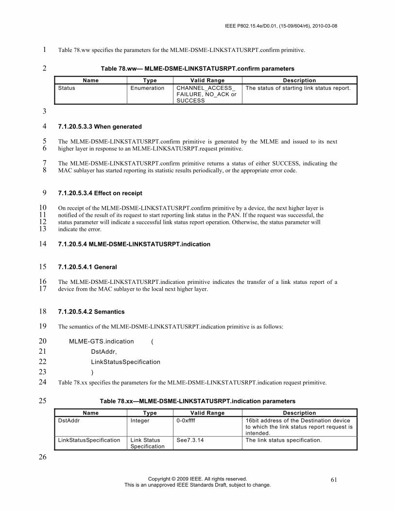
IEEE P802.15.4e/D0.01, (15-09/604/r6), 2010-03-08
Copyright © 2009 IEEE. All rights reserved. This is an unapproved IEEE Standards Draft, subject to change.
61
Table 78.ww specifies the parameters for the MLME-DSME-LINKSTATUSRPT.confirm primitive. 1
Table 78.ww— MLME-DSME-LINKSTATUSRPT.confirm parameters 2 Name Type Valid Range Description
Status Enumeration CHANNEL_ACCESS_FAILURE, NO_ACK or SUCCESS
The status of starting link status report.
3
7.1.20.5.3.3 When generated 4
The MLME-DSME-LINKSTATUSRPT.confirm primitive is generated by the MLME and issued to its next 5 higher layer in response to an MLME-LINKSATUSRPT.request primitive. 6
The MLME-DSME-LINKSTATUSRPT.confirm primitive returns a status of either SUCCESS, indicating the 7 MAC sublayer has started reporting its statistic results periodically, or the appropriate error code. 8
7.1.20.5.3.4 Effect on receipt 9
On receipt of the MLME-DSME-LINKSTATUSRPT.confirm primitive by a device, the next higher layer is 10 notified of the result of its request to start reporting link status in the PAN. If the request was successful, the 11 status parameter will indicate a successful link status report operation. Otherwise, the status parameter will 12 indicate the error. 13
7.1.20.5.4 MLME-DSME-LINKSTATUSRPT.indication 14
7.1.20.5.4.1 General 15
The MLME-DSME-LINKSTATUSRPT.indication primitive indicates the transfer of a link status report of a 16 device from the MAC sublayer to the local next higher layer. 17
7.1.20.5.4.2 Semantics 18
The semantics of the MLME-DSME-LINKSTATUSRPT.indication primitive is as follows: 19
MLME-GTS.indication ( 20 DstAddr, 21 LinkStatusSpecification 22 ) 23
Table 78.xx specifies the parameters for the MLME-DSME-LINKSTATUSRPT.indication request primitive. 24
Table 78.xx—MLME-DSME-LINKSTATUSRPT.indication parameters 25 Name Type Valid Range Description
DstAddr Integer 0-0xffff 16bit address of the Destination device to which the link status report request is intended.
LinkStatusSpecification Link Status Specification
See7.3.14 The link status specification.
26

2010-03-08, (15-09/604/r6), IEEE P802.15.4e/D0.01
Copyright © 2010 IEEE. All rights reserved. This is an unapproved IEEE Standards Draft, subject to change.
62
7.1.20.5.4.3 When generated 1
The MLME-DSME-LINKSTATUSRPT.indication primitive is generated by the MAC sublayer and issued to the 2 next higher layer on receipt of a link status report command. 3
7.1.20.5.4.4 Effect on receipt 4
On receipt of the MLME-DSME-LINKSTATUSRPT.indication primitive, the next higher layer is notified of the 5 arrival of a link status report command frame from a DSME-device. The usage of the link status report by the 6 next higher layer is beyond the scope of this document. 7
7.1.20.5.5 MLME-DSME-LINKSTATUSRPT message sequence charts 8
Figure 39.d illustrates the sequence of messages necessary for link status report initialized by a source device and 9 Figure 39.e for destination device. 10
11
Figure 39.d—Message sequence chart for link status report 12 13
14
Figure 39.e—Message sequence chart for DSME allocation initiated by a Destination device 15
Src next high layer
Dst MLME
Src MLME
MLME-LINKSTATUSRPT.requestLink status report frame
ACKMLME-LINKSTATUSRPT.confirm
MLME-LINKSTATUSRPT.indication
Dst next high layer
Src next high layer
Dst next high layer
Dst MLME
Src MLME
DSME Request
MLME -GTS indication
MLME -GTS confirm
DSME Reply
DSME Notify
MLME -GTS request

IEEE P802.15.4e/D0.01, (15-09/604/r6), 2010-03-08
Copyright © 2009 IEEE. All rights reserved. This is an unapproved IEEE Standards Draft, subject to change.
63
7.1.20.6 DSME-Beacon notification primitive 1
7.1.20.6.1 General 2
The MLME-SAP DSME-Beacon Notification primitive defines how a device may be notified when a beacon is 3 received during normal operating conditions. 4
All DSME-devices shall provide an interface for the beacon notification primitive. 5
7.1.20.6.2 MLME-DSME-BEACON-NOTIFY.indication 6
7.1.5.1 applies except Table 91 shall be amended by Table 78.yy. 7
Table 78.yy—Additional elements of DSME-PANDescriptor 8 Name Type Valid Range Description
DSMESuperframeSpec Bitmap See 7.2.2.1.2 The DSME superframe specification as specified in the received beacon frame.
BeaconBitmap Bitmap See 7.2.2.1.2 Indicates the beacon frame allocation information of neighbor nodes.
9
7.1.20.7 DSME-Primitives for channel scanning 10
7.1.20.7.1 General 11
MLME-SAP DSME-scan primitives define how a DSME-device can determine the energy usage or the presence 12 or absence of PANs in a communications channel. 13
All DSME-devices shall provide an interface for these scan primitives. 14
7.1.20.7.2 MLME-DSME-SCAN.request 15
7.1.20.7.2.1 General 16
Subclause 7.1.11.1 applies. 17
7.1.20.7.2.2 Semantics of the service primitive 18
Subclause 7.1.11.1.1 applies except the parameter ScanType in Table 103 shall be amended for the coding 0x04 19 and 0x05, see Table 78.zz. 20

2010-03-08, (15-09/604/r6), IEEE P802.15.4e/D0.01
Copyright © 2010 IEEE. All rights reserved. This is an unapproved IEEE Standards Draft, subject to change.
64
Table 78.zz—Additional elements of MLME-DSME-SCAN.request parameters 1 Name Type Valid Range Description
ScanType Integer 0x00–0x05 Indicates the type of scan performed: 0x00 = see Table 103. 0x01 = see Table 103 0x02 = see Table 103. 0x03 = see Table 103. 0x04 = asymmetric multi-channel active scan. 0x05 = channel probe.
2
7.1.20.7.2.3 Appropriate usage 3
This primitive can be used to perform an ED scan to determine channel usage, an active or passive scan to locate 4 beacon frames containing any PAN identifier, or an orphan scan to locate a PAN to which the device is currently 5 associated, or an asymmetric multi-channel active scan to detect the best designated channel for the device, or a 6 channel probe scan to probe other channels and choose a better channel to switch to. 7
7.1.20.7.2.4 Effect on receipt 8
The asymmetric multi-channel active scan is performed on each channel by the MLME first sending a multi-9 channel beacon request command (see 7.3.11). The MLME then enables the receiver and records the information 10 contained in the received beacon in a PAN descriptor structure (see Table 91 and Table 78.yy). If the 11 LinkQualityScan flag is FALSE, the asymmetric multi-channel active scan terminates when the device receives a 12 beacon and then choose the current channel as its designated channel. Otherwise, if the LinkQualityScan flag is 13 TRUE, the asymmetric multi-channel active scan on a particular channel terminates when 14 [aBaseSuperframeDuration * (2n + 1)] symbols, where n is the value of the ScanDuration parameter have 15 elapsed after successful transmission of the multi-channel beacon request command, then switch to the next 16 channel and repeat the same procedure. In this case, the whole asymmetric multi-channel active scan terminates 17 when the device have scanned every channel twice, and the device will choose its designated channel according 18 to the LQI or RSSI of the received beacons. See 7.5.11.2 for more detailed information on the asymmetric multi-19 channel active scan. 20
The channel probe scan is performed on the channel specified by the ScanChannels parameter by the MLME first 21 sending a channel probe request frame (see 7.3.11) to one of its neighbors on the designated channel of the 22 neighbor. The MLME then switch to the device own designated channel and enables the receiver and waits the 23 channel probe reply frame. The channel probe scan terminates when [aBaseSuperframeDuration * (2n + 1)] 24 symbols, where n is the value of the ScanDuration parameter have elapsed after successful transmission of the 25 channel probe request frame. The device shall check the LQI or RSSI of the channel probe reply frame upon 26 receiving it. See 7.5.11.4 for more detailed information on the channel probe scan. 27
The results of an asymmetric multi-channel active scan are reported to the next higher layer through the MLME-28 SCAN.confirm primitive. If the scan is successful and macAutoRequest is set to TRUE, the primitive results will 29 include a set of PAN descriptor values. If the scan is successful and macAutoRequest is set to FALSE, the 30 primitive results will contain a null set of PAN descriptor values, and each PAN descriptor value will be sent 31 individually to the next higher layer using separate MLME-BEACON-NOTIFY (see 7.1.5.1) primitives. In both 32 cases, the MLME-SCAN.confirm primitive will contain a list of unscanned channels and a status of SUCCESS. 33
If, during an asymmetric multi-channel active scan, the MLME is unable to transmit a multi-channel beacon 34 request command on a channel specified by the ScanChannels parameter due to a channel access failure, the 35 channel will appear in the list of unscanned channels returned by the MLME-SCAN.confirm primitive. If the 36 MLME was able to send a multi-channel beacon request command on at least one of the channels but no beacons 37 were found, the MLME-SCAN.confirm primitive will contain a null set of PAN descriptor values, regardless of 38 the value of macAutoRequest, and a status of NO_BEACON. 39
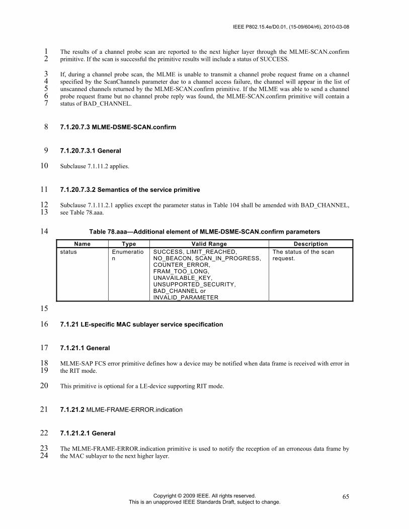
IEEE P802.15.4e/D0.01, (15-09/604/r6), 2010-03-08
Copyright © 2009 IEEE. All rights reserved. This is an unapproved IEEE Standards Draft, subject to change.
65
The results of a channel probe scan are reported to the next higher layer through the MLME-SCAN.confirm 1 primitive. If the scan is successful the primitive results will include a status of SUCCESS. 2
If, during a channel probe scan, the MLME is unable to transmit a channel probe request frame on a channel 3 specified by the ScanChannels parameter due to a channel access failure, the channel will appear in the list of 4 unscanned channels returned by the MLME-SCAN.confirm primitive. If the MLME was able to send a channel 5 probe request frame but no channel probe reply was found, the MLME-SCAN.confirm primitive will contain a 6 status of BAD_CHANNEL. 7
7.1.20.7.3 MLME-DSME-SCAN.confirm 8
7.1.20.7.3.1 General 9
Subclause 7.1.11.2 applies. 10
7.1.20.7.3.2 Semantics of the service primitive 11
Subclause 7.1.11.2.1 applies except the parameter status in Table 104 shall be amended with BAD_CHANNEL, 12 see Table 78.aaa. 13
Table 78.aaa—Additional element of MLME-DSME-SCAN.confirm parameters 14 Name Type Valid Range Description
status Enumeration
SUCCESS, LIMIT_REACHED, NO_BEACON, SCAN_IN_PROGRESS, COUNTER_ERROR, FRAM_TOO_LONG, UNAVAILABLE_KEY, UNSUPPORTED_SECURITY, BAD_CHANNEL or INVALID_PARAMETER
The status of the scan request.
15
7.1.21 LE-specific MAC sublayer service specification 16
7.1.21.1 General 17
MLME-SAP FCS error primitive defines how a device may be notified when data frame is received with error in 18 the RIT mode. 19
This primitive is optional for a LE-device supporting RIT mode. 20
7.1.21.2 MLME-FRAME-ERROR.indication 21
7.1.21.2.1 General 22
The MLME-FRAME-ERROR.indication primitive is used to notify the reception of an erroneous data frame by 23 the MAC sublayer to the next higher layer. 24

2010-03-08, (15-09/604/r6), IEEE P802.15.4e/D0.01
Copyright © 2010 IEEE. All rights reserved. This is an unapproved IEEE Standards Draft, subject to change.
66
7.1.21.2.2 Semantics of the service primitive 1
The semantics of the MLME-FRAME-ERROR.indication primitive are as follows: 2
MLME-FRAME-ERROR.indication( 3 status, 4 ) 5
Table 78.bbb specifies the parameters for the MLME-FRAME-ERROR.indication primitive. 6
Table 78.bbb— MLME-FRAME-ERROR.indication parameters 7 Name Type Valid Range Description
status Enumeration FCS_ERROR, SECURITY_ERROR
The status of the erroneous reception of data frame in RIT mode
8
7.1.21.2.3 When generated 9
The MLME-FRAME-ERROR.indication primitive is generated by MLME and issued to its next higher layer 10 upon reception of an erroneous data frame in RIT mode. 11
7.1.21.2.4 Appropriate usage 12
On receipt of the MLME-FRAME-ERROR.indication primitive, the next higher layer is notified of the reception 13 of an erroneous data frame at the MAC sublayer. 14
7.1.22 FastA-MAC sublayer service specification 15
7.1.22.1 MLME-FAST-ASSOCIATE.request 16
7.1.22.1.1 General 17
The MLME-FAST-ASSOCIATE.request primitive allows a device to request a fast association with a 18 coordinator. 19
7.1.22.1.2 Semantics 20
The semantics of the MLME-FAST-ASSOCIATE.request primitive are as follows: 21
MLME-FAST-ASSOCIATE.request ( 22 LogicalChannel, 23 ChannelPage, 24 CoordAddrMode, 25 CoordPANId, 26 CoordAddress, 27 CapabilityInformation, 28 SecurityLevel, 29 KeyIdMode, 30 KeySource, 31

IEEE P802.15.4e/D0.01, (15-09/604/r6), 2010-03-08
Copyright © 2009 IEEE. All rights reserved. This is an unapproved IEEE Standards Draft, subject to change.
67
KeyIndex 1 ) 2
7.1.22.1.3 Appropriate usage 3
The MLME-FAST-ASSOCIATE.request primitive is generated by the next higher layer of an unassociated 4 device and issued to its MLME to request a fast association with a PAN through a coordinator. 5
7.1.22.1.4 Effect on receipt 6
On receipt of the MLME-FAST-ASSOCIATE.request primitive, the MLME of an unassociated device 7 generates a fast association request command. 8
9
7.2 MAC frame formats 10
7.2.1 General MAC frame format 11
Change the first paragraph 7.2.1. 12
13
The MAC frame format is composed of a MHR, a MAC payload, and a MFR. The fields of the MHR appear in a 14 fixed order; however, the addressing fields may not be included in all frames. Furthermore, some frame types use 15 a MHR of only 1 octet length with a shortened Frame Control field. The general MAC frame shall be formatted 16 as illustrated in Figure 41. 17
Replace Figure 41 by the following figure. 18
octets: 1/2 0/1 0/2 0/2/8 0/2 0/2/8 0/5/6/10/1
4 0/1 variable 0/2
Destination PAN Identifier
Destination Address
Source PAN Identifier
Source Address Frame
control Sequence number
Addressing fields
Auxiliary Security Header
Frame Payload Header
Frame Payload FCS
MHR MAC payload MFR 19
7.2.1.1 Frame Control field 20
Change the paragraph as follows. 21
The frame control field is 1 or 2 octets in length and contains information defining the frame type, 22 addressing fields, and other control flags. For ease of reference, the 1-octet frame control field shall be 23 referred to as the short frame control field in this clause, whereas the 2-octet frame control field may be 24 referred to as the full frame control field. 25
Replace Figure 42 by the following figure. 26
bits: 2 3 4 5 6 7-8 9 10-11 12-13 14-15
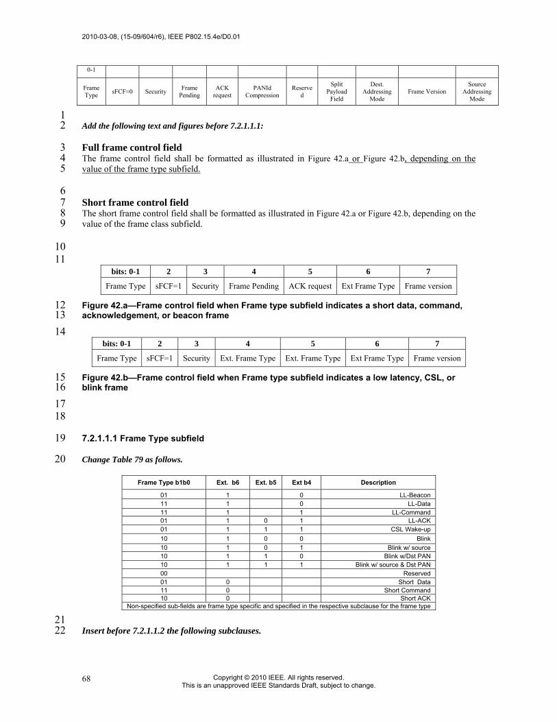
2010-03-08, (15-09/604/r6), IEEE P802.15.4e/D0.01
Copyright © 2010 IEEE. All rights reserved. This is an unapproved IEEE Standards Draft, subject to change.
68
0-1
Frame Type sFCF=0 Security Frame
Pending ACK
request PANId
Compression Reserve
d
Split Payload
Field
Dest. Addressing
Mode Frame Version
Source Addressing
Mode
1 Add the following text and figures before 7.2.1.1.1: 2
Full frame control field 3 The frame control field shall be formatted as illustrated in Figure 42.a or Figure 42.b, depending on the 4 value of the frame type subfield. 5
6 Short frame control field 7 The short frame control field shall be formatted as illustrated in Figure 42.a or Figure 42.b, depending on the 8 value of the frame class subfield. 9
10 11
bits: 0-1 2 3 4 5 6 7
Frame Type sFCF=1 Security Frame Pending ACK request Ext Frame Type Frame version
Figure 42.a—Frame control field when Frame type subfield indicates a short data, command, 12 acknowledgement, or beacon frame 13 14
bits: 0-1 2 3 4 5 6 7
Frame Type sFCF=1 Security Ext. Frame Type Ext. Frame Type Ext Frame Type Frame version
Figure 42.b—Frame control field when Frame type subfield indicates a low latency, CSL, or 15 blink frame 16 17 18
7.2.1.1.1 Frame Type subfield 19
Change Table 79 as follows. 20
Frame Type b1b0 Ext. b6 Ext. b5 Ext b4 Description
01 1 0 LL-Beacon 11 1 0 LL-Data 11 1 1 LL-Command 01 1 0 1 LL-ACK 01 1 1 1 CSL Wake-up 10 1 0 0 Blink 10 1 0 1 Blink w/ source 10 1 1 0 Blink w/Dst PAN 10 1 1 1 Blink w/ source & Dst PAN 00 Reserved 01 0 Short Data 11 0 Short Command 10 0 Short ACK
Non-specified sub-fields are frame type specific and specified in the respective subclause for the frame type
21 Insert before 7.2.1.1.2 the following subclauses. 22

IEEE P802.15.4e/D0.01, (15-09/604/r6), 2010-03-08
Copyright © 2009 IEEE. All rights reserved. This is an unapproved IEEE Standards Draft, subject to change.
69
7.2.1.1.1.1 Frame type identifier for full frame control field 1
The frame type identifier is 2 bits in length and shall be set to one of the nonreserved values listed in Table 2 79. 3
7.2.1.1.1.2 Frame type identifier for short frame control field 4
The frame type subfield is 3-5 bits in length and shall be set to one of the nonreserved values listed in Table 5 79. 6
7.2.1.1.2 Security Enabled subfield 7
7.2.1.1.3 Frame Pending subfield 8
Insert before the last paragraph the following paragraph. 9
When operating in a TSCH network, the frame pending bit can be set to one if the device sending the frame 10 has more data for the recipient. In this case, it indicates that the receiving device should remain on the same 11 channel in subsequent timeslots as long as the frame pending bit is set. Activity (or sleep) normally 12 scheduled in these subsequent timeslots is pre-empted. 13
7.2.1.1.5 14
7.2.1.1.6 Destination Addressing Mode subfield 15
Change Table 80 as follows. 16
Addressing mode value b1 b0
Description
00 PAN identifier and address fields are not present. 01 Address field contains an 8-bit simple address. 10 Address field contains a 16-bit short address. 11 Address field contains a 64-bit extended address.
17 Change the text as follows: 18
If this subfield is equal to zero, and the Frame Type subfield does not specify that this frame is an 19 acknowledgment or beacon, the Source Addressing Mode subfield shall be non-zero, implying that the 20 frame is directed to the PAN coordinator with the PAN identifier as specified in the Source PAN identifier 21 field. 22
7.2.1.1.7 Frame Version subfield 23
Insert below 7.2.1.1.7 a new subclause. 24

2010-03-08, (15-09/604/r6), IEEE P802.15.4e/D0.01
Copyright © 2010 IEEE. All rights reserved. This is an unapproved IEEE Standards Draft, subject to change.
70
7.2.1.1.7.1 Frame version subfield for long frame control field 1
Insert before 7.2.1.1.8 the following subclause: 2
7.2.1.1.7.2 Frame version subfield for short frame control field 3
The frame version subfield of the short frame control field is 1 bit in length and specifies the version 4 number corresponding to the frame. 5
This subfield shall be set to 0 to indicate a frame is compatible with IEEE 802.15.4-2006. All other subfield 6 values shall be reserved for future use. See 7.2.3 for details on frame compatibility. 7
7.2.1.1.8 Source Addressing Mode subfield 8
Insert the following subclauses before 7.2.1.2 (in a consolidated version the order should be revised so 9 that the occurrence of fields are sequential): 10
7.2.1.1.9 Short Frame Control Field Subfield 11
The Short Frame Control Field (sFCF) subfield is 1 bit in length and shall be set to one if the frame control 12 field is a short frame control field and shall be set to zero otherwise. 13
7.2.1.2 Sequence Number field 14
Change the text as follows: 15
The sequence number field is 1 octet in length and specifies the sequence identifier for the frame. 16
Insert the following text at the end of subclause7.2.1.2: 17
This field shall not be present if the frame type indicates an LL-frame type and the security enabled 18 subfield is set to zero. 19

IEEE P802.15.4e/D0.01, (15-09/604/r6), 2010-03-08
Copyright © 2009 IEEE. All rights reserved. This is an unapproved IEEE Standards Draft, subject to change.
71
7.2.1.3 Destination PAN Identifier field 1
7.2.1.4 Destination Address field 2
7.2.1.5 Source PAN Identifier field 3
7.2.1.6 Source Address field 4
7.2.1.7 Auxiliary Security Header field 5
7.2.1.8 Frame Payload field 6
7.2.1.9 FCS field 7
Insert at the end of the 1st paragraph the following text: 8
This field shall be present only if the security enabled subfield is set to zero or if frame protection does not 9 result in data expansion of the frame payload field (see Figure 41). 10
Insert the following subclauses before 7.2.2 (in a consolidated version the order should be revised so that 11 the occurrence of fields are sequential): 12
7.2.1.10 Split payload subfield 13
The Split Payload subfield is 1 bit in length and shall be set to one if the frame payload consists of at least 14 two distinct subfields and shall be set to zero otherwise. This subfield shall be ignored for the 15 acknowledgement frame type. If this subfield is set, the frame version shall be set to 0x02. 16
NOTE—The split payload field is only present in the full frame control field. 17
7.2.1.11 Frame payload header field 18
The frame payload header field is a 1-octet field and shall be set to one of the non-reserved values in 19 Table 80.a. 20
Table 80.a—Values of the Frame payload header field 21 Frame payload header Description 0x00 CSL sync field 0x01- 0xff Reserved
22

2010-03-08, (15-09/604/r6), IEEE P802.15.4e/D0.01
Copyright © 2010 IEEE. All rights reserved. This is an unapproved IEEE Standards Draft, subject to change.
72
7.2.2 Format of individual frame types 1
7.2.2.1 Beacon frame format 2
Change Figure 44 as follows: 3
octets: 1/2 1 4/10 0/5/6/10/14 2 variable variable variable 0/2
Frame Control
Sequence Number
Addressing fields
Auxiliary Security Header
Sperframe Specification
GTS fields (Figure 45)
Pending address fields (Figure 46)
Beacon Payload
FCS
MHR MAC payload MFR
Figure 44—Beacon frame format 4
7.2.2.1.1 Beacon frame MHR fields 5
Change the second paragraph as follows: 6
In the Frame Control field, the Frame Type subfield shall contain the value that indicates a beacon frame, 7 as shown in Table 79, and the Source Addressing Mode subfield shall be set as appropriate for the address 8 of the coordinator transmitting the beacon frame. If protection is used for the beacon, the Security Enabled 9 subfield shall be set to one. The Frame Version subfield shall be set to a value unequal to 0x00 only if the 10 Security Enabled subfield is set to one. If a broadcast data or command frame is pending, the Frame 11 Pending subfield shall be set to one. All other subfields shall be set to zero and ignored on reception. 12
7.2.2.2 Data frame format 13
Change Figure 52 as follows: 14
octets: 1/2 1 4/10 0/5/6/10/14 variable 0/2
Frame Control
Sequence Number
Addressing fields Auxiliary Security Header Data Payload FCS
MHR MAC payload MFR
Figure 52—Data frame format 15 16
7.2.2.3 Acknowledgment frame format 17
Replace Fig.53 by the following figure. 18

IEEE P802.15.4e/D0.01, (15-09/604/r6), 2010-03-08
Copyright © 2009 IEEE. All rights reserved. This is an unapproved IEEE Standards Draft, subject to change.
73
octets: 1/2 0/1 0/2 0/2/8 0/2 1/2/2008 0/5/6/10/14 variable 0/2
Destination PAN
Identifier
Destination Address
Source PAN
Identifier
Source Address Frame
control Sequence number
Adddressing fields
Auxiliary Security Header
Frame Payload FCS
MHR MAC payload MFR
1
7.2.2.3.1 Acknowledgment frame MHR fields 2
Insert at the end of 7.2.2.3.1 the following text and new subclauses. 3
The MHR for an acknowledgment frame shall contain the Short Frame Control field, the Sequence Number 4 field, and may contain addressing fields of the originator of the frame. 5
In the Short Frame Control field, the subfields identifying the frame type shall contain the value that 6 indicates an acknowledgment frame, as shown in Figure 53.a. 7
bits: 0 1 2 3 4 5 6 7
0 1 1 Security Frame Pending
Source Addressing
Mode 0 Frame
version
Frame Control Field
Figure 53.a—Short Frame Control field 8 If protection is used for the acknowledgement frame, the Security Enabled subfield shall be set to one. The 9 Frame Version subfield of the Short Frame Control field shall be set to the value zero, as shown in Figure 10 53.a. 11
If the acknowledgment frame is being sent in response to a received data request command, the device 12 sending the acknowledgment frame shall determine whether it has data pending for the recipient. If the 13 device can determine this before sending the acknowledgment frame (see 7.5.6.4.2), it shall set the Frame 14 Pending subfield according to whether there is pending data. Otherwise, the Frame Pending subfield shall 15 be set to one. If the acknowledgment frame is being sent in response to a data frame, another type of MAC 16 command frame, or any other MAC frame that is not a beacon frame or an acknowledgement frame, the 17 device shall set the Frame Pending subfield to zero. 18
The Sequence Number field shall contain the value of the sequence number received in the frame for which 19 the acknowledgment is to be sent. 20
The Source Address field, if present, shall contain the 64-bit extended address of the device originating the 21 acknowledgement frame. All other addressing fields shall be omitted. The presence of these addressing 22 fields shall be indicated by the Source Addressing Mode subfield of the Short Frame Control field (present 23 if set; absent otherwise). 24
If protection is used for the acknowledgement frame, the Auxiliary Security Header field shall be set to the 25 same value as the corresponding field of the frame that is being acknowledged and shall not be included in 26 the acknowledgement frame to be sent. 27

2010-03-08, (15-09/604/r6), IEEE P802.15.4e/D0.01
Copyright © 2010 IEEE. All rights reserved. This is an unapproved IEEE Standards Draft, subject to change.
74
7.2.2.3.2 Acknowledgement frame payload fields 1
7.2.2.3.2.1 General 2
The acknowledgement frame payload field has a variable length and specifies information useful for 3 synchronizing communications between sender and recipient, including loosely synchronizing timing 4 information and capability information. 5
7.2.2.3.2.2 Acknowledgement control subfield 6
7.2.2.3.2.2.1 General 7
The acknowledgement control subfield, if present, is 1 octet in length and specifies which synchronization 8 information, if any, is communicated back to the originator of the frame that is being acknowledged. This 9 field shall be present only if the MAC payload field is the non-empty string, see Figure 53.b. 10
bits: 0-2 3-4 5 6 7
ACK Identifier Reserved Time sync NAK field Security sync
Figure 53.b—Acknowledgement control field 11
12
7.2.2.3.2.2.2 ACK identifier subfield 13
The acknowledgement identifier subfield is 3 bits in length and shall be set to one of the nonreserved 14 values in Table 81.a. 15
Table 81.a—Values of the Acknowledgement identifier subfield 16 ACK identifier value Description
0x00 TSCH ACK 0x01 LE ACK
0x02-0x07 Reserved
17 Editorial note RS: 18 The so-called group ACK is not facilitated here, since feedback on this was never 19 received. 20
7.2.2.3.2.2.3 Time sync subfield 21
The Time sync subfield is 1 bit in length and shall be set to one if the acknowledgement contains time 22 synchronization information. 23
7.2.2.3.2.2.4 NAK subfield 24
The NAK subfield is 1 bit in length and shall be set to one if the incoming frame successfully passed 25 incoming frame security processing (7.5.8.2.3), but the frame could not be handled due to resource 26 constraints (e.g., insufficient buffer space). 27

IEEE P802.15.4e/D0.01, (15-09/604/r6), 2010-03-08
Copyright © 2009 IEEE. All rights reserved. This is an unapproved IEEE Standards Draft, subject to change.
75
7.2.2.3.2.2.5 Security sync subfield 1
The Time sync subfield is 1 bit in length and shall be set to one if the acknowledgement contains security 2 synchronization information. 3
7.2.2.3.2.2.6 Acknowledgement frame payload field 4
7.2.2.3.2.2.6.1 Acknowledgement frame payload field for TSCH 5
7.2.2.3.2.2.6.1.1 General 6
For TSCH, the acknowledgement frame payload field shall be formatted as illustrated in Figure 53.c. 7 octets: 0/2
Time sync info Acknowledgement Payload
Figure 53.c—Acknowledgement control field 8
7.2.2.3.2.2.6.1.2 Time sync information 9
The Time Synchronization Information subfield is 2 octets in length and shall specify time synchronization 10 information. This subfield shall be set to one of the non-reserved values in Table 81.b. 11
12 Table 81.b—Values of the time sync information subfield for TSCH 13
Range Description 0x0000-0x0FFF Time correction, in us, in one-
complement notation 0x1000-0xFFFF Reserved
14 This subfield shall be present only if the time sync subfield of the acknowledgment control field is set to 15 one. 16
7.2.2.3.2.2.6.2 Acknowledgement frame payload field for LE 17
7.2.2.3.2.2.6.2.1 General 18
For LE, the acknowledgement frame payload field shall be formatted as illustrated in Figure 53.d. 19
20 octets:0/2 octets: 0/2
CSL Phase CSL Period Acknowledgement Payload
Figure 53.d—Acknowledgement control field 21
22

2010-03-08, (15-09/604/r6), IEEE P802.15.4e/D0.01
Copyright © 2010 IEEE. All rights reserved. This is an unapproved IEEE Standards Draft, subject to change.
76
7.2.2.3.2.2.6.2.2 CSL Phase information 1
The CSL Phase subfield is 2 octets in length and shall specify CSL phase information. This subfield shall 2 be set to one of the non-reserved values in Table 81.c. 3
Table 81.c—Values of the CSL Phase subfield for LE 4 Range Description
0x0000-0x0FFF CSL Phase, in 320 us units 0x1000-0xFFFF Reserved
5 This subfield shall be present only if the time sync subfield of the acknowledgment control field is set to 6 one. 7
Editorial note RS: 8 Double check units with text provided by Wei Hong (I did not receive feedback in 9 time). 10 11
7.2.2.3.2.2.6.2.3 CSL Period information 12
The CSL Period subfield is 2 octets in length and shall specify CSL period information. This subfield shall 13 be set to one of the non-reserved values in Table 81.d. 14
Table 81.d—Values of the CSL Period subfield for LE 15 Range Description
0x0000-0x0FFF CSL Period, in 320 us units 0x1000-0xFFFF Reserved
16 This subfield shall be present only if the time sync subfield of the acknowledgment control field is set to 17 one. 18
Editorial note RS: 19 Double check units with text provided by Wei Hong (I did not receive feedback in 20 time). 21 22
7.2.2.4 MAC command frame format 23
Change Figure 54 as follows: 24
octets: 1/2 1 4/10 0/5/6/10/14 1 variable 0/2
Frame Control
Sequence Number
Addressing fields
Auxiliary Security Header
Command Frame Identifier
Command Payload FCS
MHR MAC payload MFR Figure 54—Command frame format 25

IEEE P802.15.4e/D0.01, (15-09/604/r6), 2010-03-08
Copyright © 2009 IEEE. All rights reserved. This is an unapproved IEEE Standards Draft, subject to change.
77
1
7.2.3 Frame compatibility 2
7.2.4 PA Frame Formats 3
7.2.5 LL-Frame Formats 4
Editorial note RS: 5 This entire clause §7.2.5.1 can be removed, since the functionality is provided by 6 particular instantiations of the general frame format (see §7.2.1, as described in 7 this document). 8 (Editorial note RS: this refers to LL-frame types) 9
7.2.5.1 Format of individual frame types with MHR of 1 octet 10
7.2.5.1.1 General 11
Four sub frame types are defined: beacon, data, acknowledgment, and MAC command. These sub frame types 12 are discussed in 7.2.1.1. The definition of the sub frame types is given in Figure 42.a or Figure 42.b. 13
The LL-frame shall be formatted as illustrated in Figure 53.e. 14
octets: 1 0/1 0/5/6/10/14 variable 0/2
Short Frame control
Sequence number Auxiliary Security Header
Frame Payload FCS
MHR MAC payload MFR
Figure 53.e—LL-frame format with MHR of 1 octet 15
The order of the fields of the low latency frame shall conform to the order of the general MAC frame as 16 illustrated in Figure 43. 17
18
7.2.5.1.2 Beacon frame format 19
7.2.5.1.2.1 General 20
The Beacon frame with shortened frame control (1 octet MAC header) is sent during the beacon slot in every 21 superframe. The structure of a Beacon frame depends on the current transmission mode (see 7.3.27). The general 22 structure of the beacon frame is shown in Figure 53.f. 23
24

2010-03-08, (15-09/604/r6), IEEE P802.15.4e/D0.01
Copyright © 2010 IEEE. All rights reserved. This is an unapproved IEEE Standards Draft, subject to change.
78
1 Figure 53.f—Format of the Shortened Beacon Frame 2
The beacon frame does have a very short MAC header (MHR) of one octet containing the frame type and sub 3 frame type, followed by the beacon payload and the MAC footer (MFR). The beacon payload contains the 4 transmission mode and several flags and information fields, those existences depend on the current transmission 5 mode. 6
7.2.5.1.2.2 Beacon frame MHR fields 7
The beacon frame does have a very short MAC header (MHR) of one octet containing the Shortened Frame 8 Control field. 9
In the Shortened Frame Control field, the Frame Type subfield shall contain the value that indicates a MAC 10 frame with a shortened frame control, as shown in Table 120, and the Sub Frame Type subfield shall contain the 11 value that indicates a beacon frame, as shown in Figure 53.f. 12
7.2.5.1.2.3 Flags / Beacon Payload in online mode 13
The beacon payload in online mode is of variable length. It contains flags which includes the transmission mode, 14 the Gateway ID and configuration sequence number, the size of a base time slot, and a group acknowledgement. 15 The structure of the beacon payload for beacon frames indicating online mode is depicted in Figure 53.g. 16
17
18 Figure 53.g—Beacon payload in online mode 19
20 The Flags field contains several control information. The structure of the Flags field is shown in Figure 53.h. 21
22 Figure 53.h—Structure of Flags field of Beacons with 1-octet MAC-Header in online mode 23
24 The Transmission Mode subfield defines the transmission mode. It is set to the value for online mode as 25 specified in Table 81.e. 26

IEEE P802.15.4e/D0.01, (15-09/604/r6), 2010-03-08
Copyright © 2009 IEEE. All rights reserved. This is an unapproved IEEE Standards Draft, subject to change.
79
Table 81.e—Transmission Mode settings 1 Bits 0-2 Transmission Mode
000 Online Mode (see 7.3.27.4) 100 Discovery Mode (see 7.3.27.2) 110 Configuration Mode (see 7.3.27.3) 1x1 Mode Reset: The devices reset their state of the discovery or configuration mode. The setting of bit 1 is of
no significance. 2 The Actuator Direction subfield indicates the transmission direction of all actuator time slots. The bit defines the 3 transmission direction of all actuator time slots during this superframe. If the Actuator Direction subfield is set to 4 0, the direction of all actuator time slots is uplink (from actuator to gateway). If the Actuator Direction subfield is 5 set to 1, the direction of all actuator time slots is downlink (from gateway to actuator). 6
The Number of Base Timeslots per Management Timeslot subfield contains the number of base time slots per 7 management time slot. This value applies to both the downlink and the uplink management time slot. A value of 8 0 indicates that there are no management time slots available in the superframe. 9
The Group Acknowledgement field is a bitmap of length (macFAnumTimeSlots – macFAnumRetransmitTS) bits 10 as shown in Figure 1.c and Figure 53.i to indicate failed sensor and actuator transmissions from the previous 11 superframe. In the separate group acknowledgment configuration, this field is not present in the beacon. The 12 Group Acknowledgement field contains a bit field where each bit corresponds to a time slot associated with a 13 sensor device or an actuator device excluding retransmission time slots. Bit b0 of the Group Acknowledgement 14 bitmap corresponds to the first time slot after the macFAnumRetransmitTS retransmission time slots, bit b1 of the 15 Group Acknowledgement bitmap corresponds to the second time slot, and so on. Bit value 1 means the sensor 16 transmission was successful, and bit value 0 means the sensor transmission in the previous superframe failed and 17 the sensor is allocated a time slot for retransmission in the current superframe. Because concatenated time slots 18 are multiples of base time slots, a concatenated time slot of length of n base time slots will have n bits in the 19 group acknowledgement bitmap at the corresponding positions. 20
21 Figure 53.i—Structure of Group Acknowledgement bitmap 22
If the gateway received a data frame successfully in a time slot associated with a sensor device or an actuator 23 device during the previous superframe, it shall set the corresponding bit in the Group Acknowledgement field to 24 1, otherwise to 0 (corrupted transmission, no transmission). If the data frame has been received during a shared 25 group time slot, all corresponding bits of this shared group time slot will be set accordingly in the Group 26 Acknowledgement bitmap. 27
7.2.5.1.2.4 Flags / Beacon payload for discovery and configuration mode 28
The beacon payload in discovery or configuration mode is 1 octet of length. It contains a flags field which 29 contains the transmission mode. The structure of the beacon payload for beacon frames indicating discovery or 30 configuration mode is depicted in Figure 53.j. 31
32

2010-03-08, (15-09/604/r6), IEEE P802.15.4e/D0.01
Copyright © 2010 IEEE. All rights reserved. This is an unapproved IEEE Standards Draft, subject to change.
80
Figure 53.j—Beacon payload in discovery / configuration mode 1 The Transmission Mode field is represented by 3 bits in discovery and configuration mode. The values that are 2 allowed for the setting of the transmission mode are given in Table 81.e, x meaning 0 or 1. 3
Bits 3 through 7 are reserved and set to 0 on transmission. 4
7.2.5.1.3 Data frame format 5
7.2.5.1.3.1 General 6
The structure of the data frame with shortened frame control is illustrated in Figure 53.k. 7
8 Figure 53.k—Format of Data Frame with Shortened Frame Control Field 9
The data frame does have a very short MAC header (MHR) of one octet containing the frame type and sub frame 10 type, followed by the data payload and the MAC footer (MFR). 11
7.2.5.1.3.2 Data frame MHR fields 12
The data frame does have a very short MAC header (MHR) of one octet containing the Shortened Frame Control 13 field. 14
In the Shortened Frame Control field, the Frame Type subfield shall contain the value that indicates a MAC 15 frame with a shortened frame control, as shown in Table 120, and the Sub Frame Type subfield shall contain the 16 value that indicates a data frame, as shown in Table 79. 17
7.2.5.1.3.3 Data Payload field 18
The payload of a data frame with shortened frame control shall obtain the sequence of octets that the next higher 19 layer has requested the MAC sublayer to transmit. 20
7.2.5.1.4 Acknowledgement frame format 21
7.2.5.1.4.1 General 22
The structure of the acknowledgement frame with shortened frame control is shown in Figure 53.l. 23

IEEE P802.15.4e/D0.01, (15-09/604/r6), 2010-03-08
Copyright © 2009 IEEE. All rights reserved. This is an unapproved IEEE Standards Draft, subject to change.
81
1 Figure 53.l—Format of the Shortened Acknowledgement Frame 2
The acknowledgement frame does have a very short MAC header (MHR) of one octet containing the frame type 3 and sub frame type, followed by the acknowledgement type and, if applicable, the acknowledgement payload, 4 and the MAC footer (MFR). 5
7.2.5.1.4.2 Acknowledgement frame MHR fields 6
The acknowledgement frame does have a very short MAC header (MHR) of one octet containing the Shortened 7 Frame Control field. 8
In the Shortened Frame Control field, the Frame Type subfield shall contain the value that indicates a MAC 9 frame with a shortened frame control, as shown in Table 120, and the Sub Frame Type subfield shall contain the 10 value that indicates an acknowledgement frame, as shown in Table 79. 11
7.2.5.1.4.3 Acknowledgement Type field 12
The Acknowledgement Type field is 1 octet in length and indicates the type of frame that is acknowledged. 13 Possible values are listed in Table 81.f. 14
Table 81.f—Acknowledgement Types 15 Numeric Value Acknowledged Frame Type Acknowledgement Payload
0x11 Discover Response No 0x92 Configuration Request No 0x01 Data No 0x02 Data Group ACK Yes (see 7.2.5.1.4.5) 0x03 Secure ACK Yes (see 7.2.5.2.4.6)
16
7.2.5.1.4.4 Acknowledgement Payload field 17
The Acknowledgement Payload field is only available in certain acknowledgement types as depicted in Table 18 81.f. The structure and the length of the Acknowledgement Payload field depends on the value of the 19 Acknowledgement Type field. 20
7.2.5.1.4.5 Data Group ACK (GACK) 21

2010-03-08, (15-09/604/r6), IEEE P802.15.4e/D0.01
Copyright © 2010 IEEE. All rights reserved. This is an unapproved IEEE Standards Draft, subject to change.
82
The structure of the Acknowledgement Payload field of the group acknowledgement frame is shown in Figure 1 53.m. 2
Figure 53.m—Format of the GACK Frame 3 4 The Source ID field identifies the transmitting gateway. 5
The Group Ack Flags field is a bitmap that indicates the states of transmissions of the sensors in the sensor time 6 slots of the current superframe. A bit set to 1 indicates the fact that the coordinator received the data frame 7 successfully in the corresponding time slot. A value of 0 means that the coordinator failed in receiving a data 8 frame in the corresponding slot from the sensor. 9
7.2.5.1.4.6 Secure Acknowledgement 10
Figure 53.n illustrates the format of a secure acknowledgement as used in LE and TSCH. 11
Octets: 1
Shortened Frame Control
1
Acknow-ledgement Type
1
DSN
2
Destination PAN Identifier
2
Dest ination Address
0/5/6/10/14
Auxiliary security header
2
CSL Phase
2
CSL Period
Figure 53.n— Format of secure acknowledgement 12 When operating in TSCH mode, CSL Phase and CSL period are replaced with 1 octet ACK/NACK and 2 octet 13 time correction. ACK/NACK status is a 1 octet bitmap where b0 = NACK (device could not process due to full 14 buffers) if set, and ACK if cleared. All other bits are reserved. Time correction is signed 2 octets in µs indicating 15 the arrival time of the incoming frame relative to the receiver’s time base. 16
The Shortened Frame Control field is set as follows: 17
• Frame type = 100 18
Acknowledgemen t of sensor transmission in time slot 1
b0 ...
. ..
b1 bM – 1
Source ID Group ACK Flags
Acknowledgement of sensor transmission in time slot 2
Acknowledg ement of sensor transmission in time slot M

IEEE P802.15.4e/D0.01, (15-09/604/r6), 2010-03-08
Copyright © 2009 IEEE. All rights reserved. This is an unapproved IEEE Standards Draft, subject to change.
83
• Security enabled = 0 or 1 1 • Frame version = 0 2 • Ack request = 0 3 4
The Acknowledgement Type is set to the value for Secure ACK as given in Table 122.c. 5
The DSN field is 1 octet in length and specifies the sequence identifier for the frame. The DSN field shall specify 6 a data sequence number that is used to match an acknowledgment frame to the data or MAC command frame. 7 The DSN field shall contain the value of the sequence number received in the frame for which the 8 acknowledgment is to be sent. 9
The Destination PAN Identifier field is 2 octets in length and specifies the unique PAN identifier of the intended 10 recipient of the frame. 11
The Destination Address field is 2 octets in length and specifies the address of the intended recipient of the 12 frame. 13
The 2-octet CSL Phase field and the 2-octet CSL Period field represent the CSL phase and period of the 14 receiving device. This information helps the transmitting device eliminate or reduce the wakeup sequence for 15 subsequent transmissions to the same destination. 16
7.2.5.1.5 MAC Command frame format 17
7.2.5.1.5.1 General 18
There are different types of MAC command frames with a shortened frame control. They follow the same 19 general structure of MAC command frames with shortened frame control as shown in Figure 53.o. Only the 20 Command Payload is different. 21
22 Figure 53.o—Format of the shortened Command frames 23
24 The MAC command frame does have a very short MAC header (MHR) of one octet containing the frame type 25 and sub frame type, followed by the command payload and the MAC footer (MFR). 26
7.2.5.1.5.2 MAC command frame MHR fields 27
The MAC command frame does have a very short MAC header (MHR) of one octet containing the Shortened 28 Frame Control field. 29
30

2010-03-08, (15-09/604/r6), IEEE P802.15.4e/D0.01
Copyright © 2010 IEEE. All rights reserved. This is an unapproved IEEE Standards Draft, subject to change.
84
In the Shortened Frame Control field, the Frame Type subfield shall contain the value that indicates a MAC 1 frame with a shortened frame control, as shown in Table 120, and the Sub Frame Type subfield shall contain the 2 value that indicates a MAC command frame, as shown in Table 79. 3
7.2.5.1.5.3 Command Payload field 4
The first octet of the command payload contains the command frame identifier. Table 123 contains the values 5 that are defined. 6
The remaining octets of the Command Payload field are of variable length and contain data specific to the 7 different command frame types. 8
7.2.5.2 Frame Control field 9
7.2.5.2.1 General 10
The Frame Control field is 2 octets in length and contains information defining the frame type and the sub frame 11 type. The Frame Control field shall be formatted as illustrated in Figure 53.x. 12
13
Figure 53.p—Format of Extensibility Frame 14
7.2.5.2.2 Frame Type subfield 15
The Frame Type subfield is 3 bits in length and shall be set to b111 indicating this type of Extensibility MAC 16 frame (see Table 120). The Frame Type subfield corresponds to the Frame Type subfield of the general MAC 17 frame format in 7.2.1 in meaning and position. The new type b111 allows efficient recognition of frames with the 18 extensible Subframe Type subfield (extensibility feature), but allows the usage of all other MAC frames as well. 19
7.2.5.2.3 Security Enabled subfield 20
The Security Enabled subfield is 1 bit in length, and it shall be set to one if the frame is protected by the MAC 21 sublayer and shall be set to zero otherwise. 22
7.2.5.2.4 Sub Frame Type subfield 23
The Sub Frame Type subfield is 3 bits in length. It is located at bits 7 to 9, which are reserved in IEEE 802.15.4-24 2006 MAC frames. The Sub Frame Type field allows the specification of at least additional 8 frame types, One 25 of these shall be the next extensible frame type. 26
7.2.5.2.5 Frame Version subfield 27
The Frame Version subfield is 2 bits in length and specifies the version number corresponding to the frame. 28

IEEE P802.15.4e/D0.01, (15-09/604/r6), 2010-03-08
Copyright © 2009 IEEE. All rights reserved. This is an unapproved IEEE Standards Draft, subject to change.
85
7.2.5.2.6 Other subfields 1
All other subfields may have the same meaning as in IEEE 802.15.4-2006 MAC frames as described in 7.2.1.1, 2 may be ignored / reserved, or may be redefined depending on the value of the Sub Frame Type subfield. 3
4
7.2.6 DSME-Frame Formats 5
7.2.6.1 General MAC frame format 6
Subclause 7.2.1 applies. 7
7.2.6.2 Format of individual frame types 8
7.2.6.2.1 General 9
Four frame types are defined: beacon, data, acknowledgment, and MAC command. These frame types are 10 discussed in 7.2.6.2 through 7.2.6.5. 11
7.2.6.2.2 Beacon frame format 12
7.2.6.2.2.1 General 13
The beacon frame shall be formatted as illustrated in Figure 82. 14
octets: 2 1 4/10 0/5/6/10/14 2 variable variable 4 variable 4 variable variable 2 Frame Control
Sequence Number
Addressing Fields
Auxiliary Security Header
Superframe Specification
GTS (Figure 45)
Pending address fields (Figure 46)
DSME Superframe Specification (Figure 51b)
ChannelHoppingSpecification (Figure 44a)
Time synchronization Specification (Figure 54)
Beacon Bitmap (Figure 53)
Beacon Payload
FCS
MHR MAC Payload MFR
Figure 53.q—Beacon frame format 15 All frame formats in this clause shall use the short frame control field (see 7.2.1.1.9). 16
Editorial note RS: 17 This allows lots of editorial clean-up in §7.2.5.2 of 09/604r3, All editorial changes are aimed at 18 replacing explicit cross-references to the to bit positions indicating low latency frame type to 19 corresponding name for this frame type (this is similar to referring to, e.g., security subfield of 20 the FCF, rather than to bit b3 of the FCF ["replacement of literal value by variable indicating this 21 value"]). 22 We illustrate this for the LL-beacon frame below: 23 §7.2.5.2.2 (of 09/604r3) Beacon frame 24 §7.2.5.2.2.1: 25

2010-03-08, (15-09/604/r6), IEEE P802.15.4e/D0.01
Copyright © 2010 IEEE. All rights reserved. This is an unapproved IEEE Standards Draft, subject to change.
86
l. 11: Replace “The Beacon frame with shortened frame control (1 octet MAC header)” by “The 1 LL-Beacon frame”. 2 l. 17-18: Replace “The beacon frame does have a very short MAC header (MHR) of one octet 3 containing the frame type and sub frame type, followed by the beacon payload and the MAC 4 footer (MFR)” by “The beacon frame consists of a short message header, followed by the beacon 5 payload and the MAC footer (MFR)”. 6 §7.2.5.2.2.2: Replace this clause by the following text: 7 “In the frame control field, the frame type subfield shall contain the value that indicates an LL- 8 beacon frame. 9 Editorial note RS: 10 Text below on blink frame based on email received from Dalibor Pokrajac as of Monday 11 November 30, 2009, 3:44pm EST. 12 13
7.2.6.2.2.2 Beacon frame MHR fields 14
The Frame Version subfield is 2 bits in length and specifies the version number corresponding to the frame. 15
This subfield shall be set to 0x00 to indicate a frame compatible with IEEE Std 802.15.4-2003, 0x01 to indicate 16 an IEEE Std 802.15.4-2006 frame and 0x10 to indicate an DSME-frame. All other subfield values shall be 17 reserved for future use. See 7.2.3 for details on frame compatibility. 18
7.2.6.2.2.3 Superframe Specification field 19
7.2.2.1.2 applies. 20
7.2.6.2.2.4 GTS Specification field 21
7.2.2.1.3 applies. 22
7.2.6.2.2.5 GTS Directions field 23
7.2.2.1.4 applies. 24
7.2.6.2.2.6 GTS List field 25
7.2.2.1.5 applies. 26
7.2.6.2.2.7 Pending Address Specification field 27
7.2.2.1.6 applies. 28
7.2.6.2.2.8 Address List field 29
7.2.2.1.7 applies. 30

IEEE P802.15.4e/D0.01, (15-09/604/r6), 2010-03-08
Copyright © 2009 IEEE. All rights reserved. This is an unapproved IEEE Standards Draft, subject to change.
87
7.2.6.2.2.9 Beacon Payload field 1
7.2.2.1.8 applies. 2
7.2.6.2.2.10 DSME Superframe Specification field 3
The DSME Superframe Specification field shall be formatted as illustrated in Figure 53.r. 4
bits:
0-3 4 5 6 7 8-23 24-31 32 33-35 variable
Multi-superframe Order (MO)
DSME Flag
CAP Reduction Flag
Embedded CAP/CFP Flag
ChannelDiversityMode
CAP Index
Number of Subslots
GACK Flag
ECFP Start Slot Length
ECFP Start Slot
Figure 53.r—Format of the DSME Superframe Specification field 5 The Multi-superframe Order subfield is 4 bits in length and shall specify the length of time during which a group 6 of superframes that is considered as one multi-superframe is active (i.e.. receiver enabled), including the beacon 7 frame transmission time. See 7.5.1.1 for an explanation of the relationship between the Multi-superframe Order 8 and the multi-superframe duration. 9
The DSME Flag subfield is 1 bit in length, and it shall be set to zero if the CFP of a superframe is operated the 10 same way as defined in IEEE 802.15.4-2006, and the other subfields in the DSME Superframe Specification field 11 shall all be ignored. The DSME Flag bit shall be set to one if the CFP of a superframe is operated as the DSME 12 mode (defined in 7.5.9 and 7.5.10). 13
The CAP Reduction Flag subfield is 1 bit in length and shall be set to one if the CAP reduction is enabled. 14 Otherwise, the CAP Reduction Flag subfield shall be set to zero. 15
The Embedded CAP/CFP Flag subfield is 1 bit in length, and shall be set to zero if the Embedded CAP is used 16 (see 7.5.9). The Embedded CAP/CFP Flag bit shall be set to zero if the Embedded CFP is used (see 7.5.9). 17
The CAP Index subfield is 2 octets in length and shall specify the number of superframes before the next CAP 18 begins. This subfield is valid only if the CAP Reduction Flag subfield is set to one. 19
The Number of Sub-slots subfield is 8 bits in length and shall specify the number of sub-slots which are divided 20 within a slot. This subfield is valid only if the Embedded CAP/CFP Flag subfield is set to zero. 21
The Channel Diversity mode subfield is 1 bit in length and shall indicate the type of channel diversity. If this 22 value is ‘0’, DSME runs on channel adaptation mode. If this value is ‘1’, DSME runs on channel hopping mode. 23 If this subfield is ‘0’, the following Channel Hopping Specification field is not present. 24
The GACK Flag subfield is 1 bit in length and shall indicate whether the transmitting device is using DSME 25 multi-frame structure with group acknowledgement mechanism. If the GACK Flag subfield is set to ‘1’, the 26 superframe of the transmitting device shall be using group acknowledge mechanism, and have a structure as 27 shown in Figure 8. If the GACK Flag subfield is set to ‘0’, the transmitting FFD can not support group 28 acknowledgement mechanism, the superframe structure will be shown as Figure 7, and the following ECFP Start 29 subfield is not present. 30
The ECFP Start Length subfield is 3 bits in length and shall specify the length of the ECFP Start subfield. 31
The ECFP Start subfield shall specify the timeslot number of GACK frame transmitting (see 7.5.9.3), as the end 32 of the CFP and start of the ECFP in the superframe structure as shown in Figure 8. The length of the ECFP Start 33 subfield is variable and specified by the ECFP Start Length subfield. 34
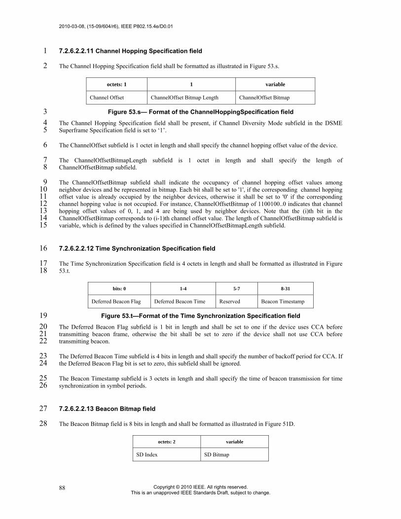
2010-03-08, (15-09/604/r6), IEEE P802.15.4e/D0.01
Copyright © 2010 IEEE. All rights reserved. This is an unapproved IEEE Standards Draft, subject to change.
88
7.2.6.2.2.11 Channel Hopping Specification field 1
The Channel Hopping Specification field shall be formatted as illustrated in Figure 53.s. 2
octets: 1 1 variable
Channel Offset ChannelOffset Bitmap Length ChannelOffset Bitmap
Figure 53.s— Format of the ChannelHoppingSpecification field 3 The Channel Hopping Specification field shall be present, if Channel Diversity Mode subfield in the DSME 4 Superframe Specification field is set to ‘1’. 5
The ChannelOffset subfield is 1 octet in length and shall specify the channel hopping offset value of the device. 6
The ChannelOffsetBitmapLength subfield is 1 octet in length and shall specify the length of 7 ChannelOffsetBitmap subfield. 8
The ChannelOffsetBitmap subfield shall indicate the occupancy of channel hopping offset values among 9 neighbor devices and be represented in bitmap. Each bit shall be set to '1', if the corresponding channel hopping 10 offset value is already occupied by the neighbor devices, otherwise it shall be set to '0' if the corresponding 11 channel hopping value is not occupied. For instance, ChannelOffsetBitmap of 1100100..0 indicates that channel 12 hopping offset values of 0, 1, and 4 are being used by neighbor devices. Note that the (i)th bit in the 13 ChannelOffsetBitmap corresponds to (i-1)th channel offset value. The length of ChannelOffsetBitmap subfield is 14 variable, which is defined by the values specified in ChannelOffsetBitmapLength subfield. 15
7.2.6.2.2.12 Time Synchronization Specification field 16
The Time Synchronization Specification field is 4 octets in length and shall be formatted as illustrated in Figure 17 53.t. 18
bits: 0 1-4 5-7 8-31
Deferred Beacon Flag Deferred Beacon Time Reserved Beacon Timestamp
Figure 53.t—Format of the Time Synchronization Specification field 19 The Deferred Beacon Flag subfield is 1 bit in length and shall be set to one if the device uses CCA before 20 transmitting beacon frame, otherwise the bit shall be set to zero if the device shall not use CCA before 21 transmitting beacon. 22
The Deferred Beacon Time subfield is 4 bits in length and shall specify the number of backoff period for CCA. If 23 the Deferred Beacon Flag bit is set to zero, this subfield shall be ignored. 24
The Beacon Timestamp subfield is 3 octets in length and shall specify the time of beacon transmission for time 25 synchronization in symbol periods. 26
7.2.6.2.2.13 Beacon Bitmap field 27
The Beacon Bitmap field is 8 bits in length and shall be formatted as illustrated in Figure 51D. 28
octets: 2 variable
SD Index SD Bitmap

IEEE P802.15.4e/D0.01, (15-09/604/r6), 2010-03-08
Copyright © 2009 IEEE. All rights reserved. This is an unapproved IEEE Standards Draft, subject to change.
89
Figure 53.u—Format of the Beacon Bitmap field 1 The SD Index subfield is 2 octets in length and specifies the Superframe Duration (SD) bank number that is 2 allocated to the Source device of the beacon. 3
The SD Bitmap subfield is 2(BO-SO) bits in length and shall indicate the beacon frame allocation information of 4 neighbor nodes. This subfield is expressed in bitmap format which orderly represents the schedule of beacons, 5 with corresponding bit shall be set to one if a beacon of neighbor nodes is allocated in that SD. 6
7.2.6.2.3 Data frame format 7
Subclause 7.2.2.2 applies. 8
7.2.6.2.4 Acknowledgment frame format 9
Subclause 7.2.2.3 applies. 10
7.2.6.2.5 Data Group ACK (GACK) 11
As opposed to the acknowledgement to aindividual frames, the structure of a group ACK frame is more 12 complex. A group acknowledgement not only indicates the reception status for a group of GTS data frames 13 but it also spacifies new slot allocations, if any, for retransmission of failed GTS transmissions. The 14 structure of the Acknowledgement Payload field of the group acknowledgement frame is shown in Figure 15 53.v. 16
17
Figure 53.v—Format of the GACK Frame 18
PAN ID: This field shall identify the PAN of the transmitting coordinator. 19
Source ID: This field shall identify the transmitting LL_NW PAN coordinator. 20
Group Ack Flags: It is a bitmap that indicates the state of transmission in each GTS in previous SCFP or 21 ECFP. A bit having ‘1’ indicates the fact that the coordinator received the data frame successfully in the 22 corresponding GTS. A ‘0’ means that the coordinator failed in receiving a data frame in the corresponding 23 slot. 24
Channel Index: This field specifies the channel sequence to be followed in the ECFP or a tailing CAP, if 25 allowed in a system, in a channel hopping system. This field shall be non-existent in the GACK 2 frame. 26
DSME Device List: This list identifies the sensor nodes that are being allocated the time slots in ECFP 27 portion of the superframe. This field shall be non-existent in the GACK 2 frame. 28
DSME Index: It is a list that specifies the start of each GTS for the allocated nodes in the same order as in 29 DSME device list. This field is applicable only in those systems that allow a GTS to consist of multiple 30 time slots. This field shall be non-existent in the GACK 2 frame. 31
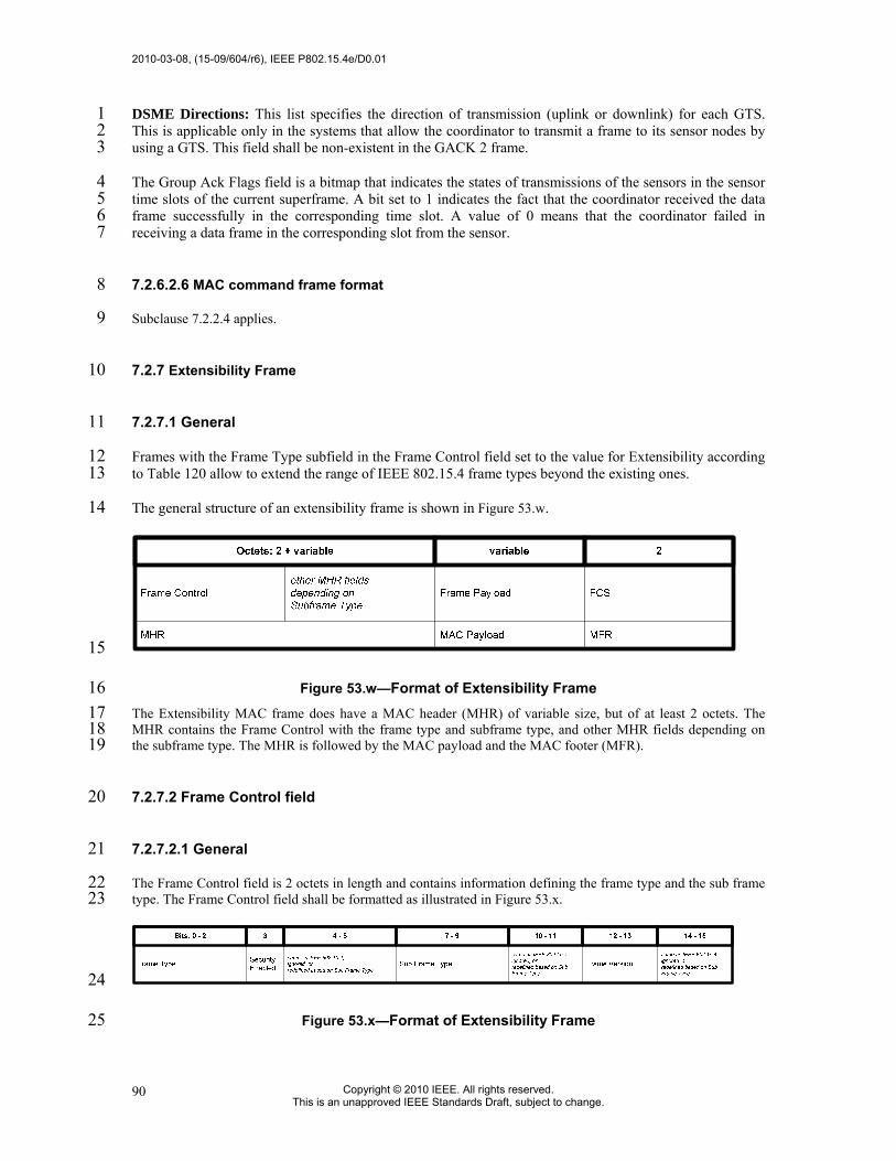
2010-03-08, (15-09/604/r6), IEEE P802.15.4e/D0.01
Copyright © 2010 IEEE. All rights reserved. This is an unapproved IEEE Standards Draft, subject to change.
90
DSME Directions: This list specifies the direction of transmission (uplink or downlink) for each GTS. 1 This is applicable only in the systems that allow the coordinator to transmit a frame to its sensor nodes by 2 using a GTS. This field shall be non-existent in the GACK 2 frame. 3
The Group Ack Flags field is a bitmap that indicates the states of transmissions of the sensors in the sensor 4 time slots of the current superframe. A bit set to 1 indicates the fact that the coordinator received the data 5 frame successfully in the corresponding time slot. A value of 0 means that the coordinator failed in 6 receiving a data frame in the corresponding slot from the sensor. 7
7.2.6.2.6 MAC command frame format 8
Subclause 7.2.2.4 applies. 9
7.2.7 Extensibility Frame 10
7.2.7.1 General 11
Frames with the Frame Type subfield in the Frame Control field set to the value for Extensibility according 12 to Table 120 allow to extend the range of IEEE 802.15.4 frame types beyond the existing ones. 13
The general structure of an extensibility frame is shown in Figure 53.w. 14
15
Figure 53.w—Format of Extensibility Frame 16 The Extensibility MAC frame does have a MAC header (MHR) of variable size, but of at least 2 octets. The 17 MHR contains the Frame Control with the frame type and subframe type, and other MHR fields depending on 18 the subframe type. The MHR is followed by the MAC payload and the MAC footer (MFR). 19
7.2.7.2 Frame Control field 20
7.2.7.2.1 General 21
The Frame Control field is 2 octets in length and contains information defining the frame type and the sub frame 22 type. The Frame Control field shall be formatted as illustrated in Figure 53.x. 23
24
Figure 53.x—Format of Extensibility Frame 25

IEEE P802.15.4e/D0.01, (15-09/604/r6), 2010-03-08
Copyright © 2009 IEEE. All rights reserved. This is an unapproved IEEE Standards Draft, subject to change.
91
7.2.7.2.2 Frame Type subfield 1
The Frame Type subfield is 3 bits in length and shall be set to b111 indicating this type of Extensibility MAC 2 frame (see Table 120). The Frame Type subfield corresponds to the Frame Type subfield of the general MAC 3 frame format in 7.2.1 in meaning and position. The new type b111 allows efficient recognition of frames with the 4 extensible Subframe Type subfield (extensibility feature), but allows the usage of all other MAC frames as well. 5
7.2.7.2.3 Security Enabled subfield 6
The Security Enabled subfield is 1 bit in length, and it shall be set to one if the frame is protected by the MAC 7 sublayer and shall be set to zero otherwise. 8
7.2.7.2.4 Sub Frame Type subfield 9
The Sub Frame Type subfield is 3 bits in length. It is located at bits 7 to 9, which are reserved in IEEE 802.15.4-10 2006 MAC frames. The Sub Frame Type field allows the specification of at least additional 8 frame types, One 11 of these shall be the next extensible frame type. 12
7.2.7.2.5 Frame Version subfield 13
The Frame Version subfield is 2 bits in length and specifies the version number corresponding to the frame. 14
7.2.7.2.6 Other subfields 15
All other subfields may have the same meaning as in IEEE 802.15.4-2006 MAC frames as described in 7.2.1.1, 16 may be ignored / reserved, or may be redefined depending on the value of the Sub Frame Type subfield. 17
7.2.8 Blink frame format 18
7.2.8.1 General 19
The blink frame shall be formatted as illustrated in Figure 53.y. 20
octets: 1/2 1 0/2 0/8 0/5/6/10/14 variable 0/2
Destination PAN Identifier Source Address Frame
control Sequence number
Adddressing fields
Auxiliary Security Header
Frame Payload FCS
MHR MAC payload MFR
Figure 53.y—Blink frame format 21 The order of the fields of the blink frame shall conform to the order of the general MAC frame as 22 illustrated in Figure 43. 23

2010-03-08, (15-09/604/r6), IEEE P802.15.4e/D0.01
Copyright © 2010 IEEE. All rights reserved. This is an unapproved IEEE Standards Draft, subject to change.
92
7.2.8.2 Blink frame MHR fields 1
The MHR for a blink frame shall contain the Short Frame Control Field, the Sequence Number Field, and 2 optionally the Destination PAN Id and/or the Source Address field. 3
In the Short Frame Control Field, the Frame Type shall contain the value that indicates a blink frame, as 4 shown in Table 81.g. 5
Table 81.g—Blink frame format 6 Bit
0, 1 2 3 4 5 6 7
A-Class sFCF=1 Security Source addressing mode
Destination PAN
Identifier 1 Frame
version
7 If protection is used for the wake-up frame, the Security Enabled subfield shall be set to one. 8
The Frame Version subfield of the Short Frame Control Field shall be set to the value zero. 9
The Sequence Number field shall be set to the current value of macDSN. 10
The Destination PAN Identifier field, if present, shall contain the PAN Identifier of the device receiving the 11 blink frame. The Source Address field, if present, shall contain the extended address of the device 12 originating the blink frame. All other addressing fields shall be omitted. The presence of these addressing 13 fields shall be indicated by the Destination PAN Identifier subfield and the Source Addressing subfield of 14 the Short Frame Control field, respectively (present if set; absent otherwise). 15
7.2.8.3 Blink frame payload field 16
The blink frame payload field is an optional sequence specified to be transmitted by the next higher layer. 17 The set of octets contained in macBlinkPayload shall be copied into this field. 18
NOTE— The payload field, if present, is expected to encode and alternative identifier for the originating 19 device. The details of this encoding are outside scope of this specification. 20
7.3 MAC command frames 21
Change the first two paragraphs according to the text below. 22
The command frames defined by the MAC sub-layer are listed in Table 123. An FFD shall be capable of 23 transmitting and receiving all command frame types, with the exception of the GTS request command, while the 24 requirements for an RFD are indicated in the table. MAC commands shall only be transmitted in the CAP for 25 beacon-enabled PANs, in management time slots of Low Latency networks, or at any time for non-beacon-26 enabled PANs. 27
28 How the MLME shall construct the individual commands for transmission is detailed in 7.3.1 through 7.3.129. 29 MAC command reception shall abide by the procedure described in 7.5.6.2. 30

IEEE P802.15.4e/D0.01, (15-09/604/r6), 2010-03-08
Copyright © 2009 IEEE. All rights reserved. This is an unapproved IEEE Standards Draft, subject to change.
93
7.3.1 Association request command 1
Change the Table 82 according to the Table below. 2
Table 82—MAC command frames 3 RFD Command
frame identifier
Command name Tx Rx
Sub-clause
0x01 Association request X 7.3.1 0x02 Association response X 7.3.2 0x03 Disassociation notification X X 7.3.3 0x04 Data request X 7.3.4 0x05 PAN ID conflict notification X 7.3.5 0x06 Orphan notification X 7.3.6 0x07 Beacon request 7.3.7 0x08 Coordinator realignment X 7.3.8 0x09 GTS request 7.3.9 0x0a–0xff Reserved — 0x0a TSCH-Advertisement X 7.3.10.1 0x0b TSCH-Join X 7.3.10.2 0x0c TSCH-Activate X 7.3.10.3 0x0d LL-Discover Response X 7.3.11.1 0x0e LL-Configuration Response X 7.3.11.2 0x0f LL-Configuration Request X 7.3.11.3 0x10 LL-CTS Shared Group X 7.3.11.4 0x11 LL-Request to send (RTS) X X 7.3.11.5 0x12 LL-Clear to Send (CTS) X 7.3.11.6 0x13 DSME-handshake X X 7.3.12.4 0x14 DSME-information request X 7.3.12.5 0x15 DSME-information reply X 7.3.12.6 0x16 DSME-Beacon allocation
notification 7.3.12.7
0x17 DSME-Beacon collision notification X 7.3.12.8 0x18 DSME-Link status report X X 7.3.12.9 0x19 DSME-Asymmetric multi-channel
beacon request X X 7.3.12.10
0x1a DSME-Multi-channel hello X X 7.3.12.11 0x1b DSME-Multi-channel hello reply X X 7.3.12.12 0x1c DSME-Channel probe X X 7.3.12.13 0x1d EBR-Enhanced Beacon request X 7.3.13.1 0x1e LE-RIT data request X X 7.3.14.1 0x1f LE-Wakeup X X 7.3.14.2 0x20 FAST-ASSOCIATE.request X 7.3.16.2 0x21–0x3f Reserved — 0x40 RFID Blink X 7.3.15 0x41-0x42 Reserved — 0x43 RFID Blink with 64-bit source MAC
address X 7.3.15
0x44-0x5f Reserved — 0x60 RFID Blink with Destination PAN ID X 7.3.15 0x61-0x62 Reserved — 0x63 RFID Blink with Destination PAN ID
and 64-bit source MAC address X 7.3.15
0x64-0xff Reserved —
4

2010-03-08, (15-09/604/r6), IEEE P802.15.4e/D0.01
Copyright © 2010 IEEE. All rights reserved. This is an unapproved IEEE Standards Draft, subject to change.
94
7.3.2 Association response command 1
7.3.2.1 MHR fields 2
7.3.2.2 Short Address field 3
7.3.2.3 Association Status field 4
Change the Table 83 according to the Table below. 5
Association status Description 0x00 Association successful. 0x01 PAN at capacity. 0x02 PAN access denied.
0x03 Channel hopping sequence offset duplication (see 7.3.12.3.6)
0x043-0x7f Reserved.
0x80-0xff Reserved for MAC primitives enumeration values.
6 7
7.3.8 Coordinator realignment command 8
7.3.9 GTS request command 9
Insert before 0 the following subclauses. 10
7.3.10 TSCH-commands 11
7.3.10.1 Advertisement command 12
7.3.10.1.1 General 13
The Advertisement command is used by FFDs to invite new devices into the network. When a device wishes to 14 join a network, it shall use the information in Advertisement command frames to synchronize to the network and 15 request an association. Figure 65.a shows the format of the Advertisement command. 16
17

IEEE P802.15.4e/D0.01, (15-09/604/r6), 2010-03-08
Copyright © 2009 IEEE. All rights reserved. This is an unapproved IEEE Standards Draft, subject to change.
95
octets: variable
(see 7.2.2.4)
1 6 1 1 1 0/22 1 0/1 variable 0/1 1 1 variable
MHR Command Frame Identifier (see table 82)
Timing Infor mation
Security Control Field
Join Control
Timeslot Template
Timeslot Template (without Timeslot Template ID)
Hopping Sequence
Hopping Sequence Length
Hopping Sequence
Current hop in sequence
Channel Page/Map Length
Channel Page
Channel Map
Figure 65.a—Advertisement command format 1 2
7.3.10.1.2 MHR field 3
The Source Addressing Mode subfield of the Frame Control field shall be set to three (64-bit extended 4 addressing). The Destination Addressing Mode subfield shall be set to the broadcast address, i.e. 0xFFFF. 5
The Frame Pending subfield of the Frame Control field shall be set to zero and ignored upon receipt, and the 6 Acknowledgment Request subfield shall be set to zero. The Source PAN Identifier field shall contain the PAN 7 identifier of the node. The Source Address field shall contain the value of aExtendedAddress. 8
The Sequence Number subfield shall be set to the least significant byte of the absolute slot number. 9
7.3.10.1.3 Command Frame Identifier field 10
The Type field shall be set to Advertisement (0x0a). 11
7.3.10.1.4 Timing Information field 12
The Timing Information field shall be set to the time information (i.e. Absolute Slot Number) of the timeslot 13 being used for transmission of this command frame. 14
7.3.10.1.5 Security Control field 15
Figure 65.b shows the Security Control field. 16
Bit 4–7 Bit 0–3 Reserved Security Level
Figure 65.b—Security Control field 17 The Security Level subfield should be set to the security level supported. The definition of the Security Level 18 subfield can be found in Table 95. 19
7.3.10.1.6 Join Control field 20
Figure 65.c shows the Join Control field. 21
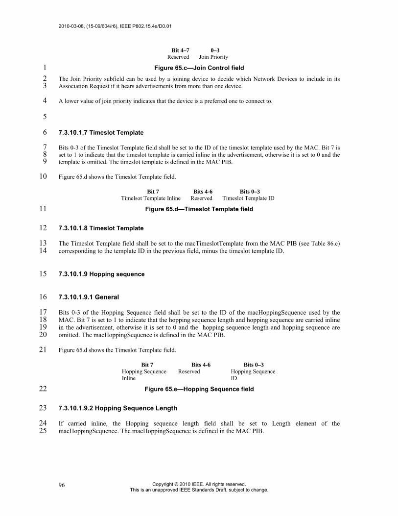
2010-03-08, (15-09/604/r6), IEEE P802.15.4e/D0.01
Copyright © 2010 IEEE. All rights reserved. This is an unapproved IEEE Standards Draft, subject to change.
96
Bit 4–7 0–3 Reserved Join Priority
Figure 65.c—Join Control field 1 The Join Priority subfield can be used by a joining device to decide which Network Devices to include in its 2 Association Request if it hears advertisements from more than one device. 3
A lower value of join priority indicates that the device is a preferred one to connect to. 4
5
7.3.10.1.7 Timeslot Template 6
Bits 0-3 of the Timeslot Template field shall be set to the ID of the timeslot template used by the MAC. Bit 7 is 7 set to 1 to indicate that the timeslot template is carried inline in the advertisement, otherwise it is set to 0 and the 8 template is omitted. The timeslot template is defined in the MAC PIB. 9
Figure 65.d shows the Timeslot Template field. 10
Bit 7 Bits 4-6 Bits 0–3 Timelsot Template Inline Reserved Timeslot Template ID
Figure 65.d—Timeslot Template field 11
7.3.10.1.8 Timeslot Template 12
The Timeslot Template field shall be set to the macTimeslotTemplate from the MAC PIB (see Table 86.e) 13 corresponding to the template ID in the previous field, minus the timeslot template ID. 14
7.3.10.1.9 Hopping sequence 15
7.3.10.1.9.1 General 16
Bits 0-3 of the Hopping Sequence field shall be set to the ID of the macHoppingSequence used by the 17 MAC. Bit 7 is set to 1 to indicate that the hopping sequence length and hopping sequence are carried inline 18 in the advertisement, otherwise it is set to 0 and the hopping sequence length and hopping sequence are 19 omitted. The macHoppingSequence is defined in the MAC PIB. 20
Figure 65.d shows the Timeslot Template field. 21
Bit 7 Bits 4-6 Bits 0–3 Hopping Sequence Inline
Reserved Hopping Sequence ID
Figure 65.e—Hopping Sequence field 22
7.3.10.1.9.2 Hopping Sequence Length 23
If carried inline, the Hopping sequence length field shall be set to Length element of the 24 macHoppingSequence. The macHoppingSequence is defined in the MAC PIB. 25

IEEE P802.15.4e/D0.01, (15-09/604/r6), 2010-03-08
Copyright © 2009 IEEE. All rights reserved. This is an unapproved IEEE Standards Draft, subject to change.
97
7.3.10.1.9.3 Hopping Sequence 1
If carried inline, the Hopping sequence field shall be set to Hopping sequence element of the 2 macHoppingSequence. The macHoppingSequence is defined in the MAC PIB. 3
7.3.10.1.9.4 Current Hop in Sequence 4
If carried inline, the Current Hop in Sequence field shall be set to current location in the hopping sequence 5 element of the macHoppingSequence corresponding to the ASN in the Timing Information field in the 6 advertisement. The macHoppingSequence is defined in the MAC PIB. 7
7.3.10.1.10 Channel Page/Map Length field 8
The Channel Page/Map field shall be set to the combined length of following channel page and channel map 9 fields. 10
7.3.10.1.11 Channel Page field 11
The Channel Page field shall be set to the channel page of channels that the joining device shall use for its 12 hopping sequence. 13
7.3.10.1.12 Number of Slotframes field 14
The Number of Slotframes field is set to the total number of slotframes for which information is being advertised 15 in this command frame. 16
7.3.10.1.13 Slotframe Information and Links (for each slotframe) field 17
7.3.10.1.14 General 18
Slotframe Information and Links field is included for each slotframe. The format of Slotframe Information and 19 Links field is depicted as shown in Figure 65.f. 20
21 Octets: 1 2 1 Variable
Slotframe ID
Slotframe Size
Number of
Links
Link Info. for each Link
Figure 65.f—Slotframe and Links field 22 23
7.3.10.1.15 Slotframe ID subfield 24
Slotframe ID shall be set to the ID that uniquely identifies the slotframe. 25

2010-03-08, (15-09/604/r6), IEEE P802.15.4e/D0.01
Copyright © 2010 IEEE. All rights reserved. This is an unapproved IEEE Standards Draft, subject to change.
98
7.3.10.1.16 Slotframe Size subfield 1
Slotframe Size shall be set to the size of the slotframe in number of timeslots. 2
7.3.10.1.17 Number of Links subfield 3
The Number of Links subfield shall be set to the number of links that belong to the specific slotframe indicated 4 in preceding slotframe ID. 5
7.3.10.1.18 Link Information (for each link) subfield 6
The Link Information subfield describes the attributes of each link. The format of Link Information subfield is 7 depicted as shown in Figure 65.g. 8
9 Octets: 2 1 1
Timeslot Channel Offset Link Option
Figure 65.g—Link Information field 10
7.3.10.1.19 Timeslot subfield 11
The Timeslot subfield shall be set to the timeslot of this link. 12
7.3.10.1.20 Channel Offset Information subfield 13
The Channel Offset Information subfield shall be set to the channel offset of this link. 14
7.3.10.1.21 Link Option subfield 15
The Link Option subfield indicates whether this link is a TX link, an RX link, or a SHARED TX link. SHARED 16 TX links can be used for a joining device to send its Join command. RX links are used for a new device to 17 receive Advertisement commands. RX links can also be used for a joining device to receive its Activate 18 command from the network. It is possible for one link to be used as both SHARED_TX and RX link. 19
7.3.10.1.22 MIC 20
The message integrity check of the Advertisement command frame. 21
7.3.10.2 Join command 22
7.3.10.2.1 General 23
The Join command is used by a device to join the TSCH-network through the advertiser. This command shall 24 only be sent by a new device that wishes to join the TSCH-network or a device that lost connection with the 25 TSCH-network. 26
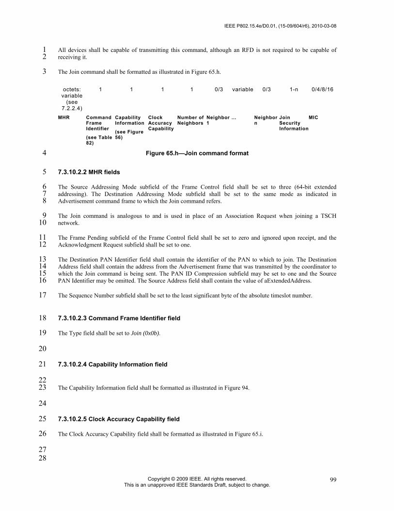
IEEE P802.15.4e/D0.01, (15-09/604/r6), 2010-03-08
Copyright © 2009 IEEE. All rights reserved. This is an unapproved IEEE Standards Draft, subject to change.
99
All devices shall be capable of transmitting this command, although an RFD is not required to be capable of 1 receiving it. 2
The Join command shall be formatted as illustrated in Figure 65.h. 3
octets: variable
(see 7.2.2.4)
1 1 1 1 0/3 variable 0/3 1-n 0/4/8/16
MHR Command Frame Identifier
(see Table 82)
Capability Information
(see Figure 56)
Clock Accuracy Capability
Number of Neighbors
Neighbor 1
... Neighbor n
Join Security Information
MIC
Figure 65.h—Join command format 4
7.3.10.2.2 MHR fields 5
The Source Addressing Mode subfield of the Frame Control field shall be set to three (64-bit extended 6 addressing). The Destination Addressing Mode subfield shall be set to the same mode as indicated in 7 Advertisement command frame to which the Join command refers. 8
The Join command is analogous to and is used in place of an Association Request when joining a TSCH 9 network. 10
The Frame Pending subfield of the Frame Control field shall be set to zero and ignored upon receipt, and the 11 Acknowledgment Request subfield shall be set to one. 12
The Destination PAN Identifier field shall contain the identifier of the PAN to which to join. The Destination 13 Address field shall contain the address from the Advertisement frame that was transmitted by the coordinator to 14 which the Join command is being sent. The PAN ID Compression subfield may be set to one and the Source 15 PAN Identifier may be omitted. The Source Address field shall contain the value of aExtendedAddress. 16
The Sequence Number subfield shall be set to the least significant byte of the absolute timeslot number. 17
7.3.10.2.3 Command Frame Identifier field 18
The Type field shall be set to Join (0x0b). 19
20
7.3.10.2.4 Capability Information field 21
22 The Capability Information field shall be formatted as illustrated in Figure 94. 23
24
7.3.10.2.5 Clock Accuracy Capability field 25
The Clock Accuracy Capability field shall be formatted as illustrated in Figure 65.i. 26
27 28

2010-03-08, (15-09/604/r6), IEEE P802.15.4e/D0.01
Copyright © 2010 IEEE. All rights reserved. This is an unapproved IEEE Standards Draft, subject to change.
100
Bit: 0 1 - 7 10ppm capable reserved
Figure 65.i—Clock Accuracy Capability 1 Bit 0 is to be set if the joining device has a timeslot clock that is at least 10 ppm accurate, i.e. the device 2 will drift no more than 10 µs for every second between synchronization messages as described in 3 7.3.22.4.2. 4
7.3.10.2.6 Join Security Information field 5
The Join Security field is 1 octet bitmap where b0 = pre-shared symmetric key (as configured by a higher layer), 6 b1=public key. If no bit is set, security is off. All other bits are reserved. If b1 is set, then an additional public 7 key (TBD) follows the security field. 8
7.3.10.2.7 Number of Neighbor field 9
The Number of Neighbor field indicates the number of neighbors included in this command frame. 10
7.3.10.2.8 Neighbor field 11
The Neighbor field shall contain the information about the neighbors of the new device. The Neighbor field shall 12 be formatted as illustrated in Figure 65.i. 13
14
15 Octets: 2 1
16 bit address of the neighbor RSSI
Figure 65.j—Neighbor 16
7.3.10.2.9 MIC 17
This field contains the message integrity check of the Join command frame. 18
7.3.10.3 Activate command 19
7.3.10.3.1 General 20
The Activate command allows the advertiser to communicate the results of a Join attempt back to the device 21 requested joining. The Activate command can also include the description of slotframe and links for the joining 22 device to communicate with the TSCH-network. 23
The Activate command is analogous to and is used in place of an Association Response when joining a TSCH 24 network. If links are included in the Activate command frame, those neighbors are used as clock sources as 25 described in 0. 26
This command shall only be sent by the advertiser to the device that is currently trying to join. 27
All devices shall be capable of receiving this command, although an RFD is not required to be capable of 28 transmitting it. 29

IEEE P802.15.4e/D0.01, (15-09/604/r6), 2010-03-08
Copyright © 2009 IEEE. All rights reserved. This is an unapproved IEEE Standards Draft, subject to change.
101
The Activate command shall be formatted as illustrated in Figure 65.k. 1
Octets: (see 7.2.2.4)
1 2 1 variable 1-n 0/4/8/16
MHR fields Command frame Identifier (see Table 123)
Short Address Number of Slot-frames
Slotframe Info. and Links (for Each Slotframe)
Activate Security Information
MIC
Figure 65.k— Activate command format 2
7.3.10.3.2 MHR 3
The Destination Addressing Mode subfield of the Frame Control field shall be set to three (i.e., 64-bit extended 4 addressing). The Source Addressing Mode subfield of the Frame Control field shall be set to two (i.e., 16-bit 5 addressing). 6
The Frame Pending subfield of the Frame Control field shall be set to zero and ignored upon receipt, and the 7 Acknowledgment Request subfield shall be set to one. 8
The Source PAN Identifier field shall contain the value of macPANId. The Source Address field shall contain the 9 value of macCoordShortAddress. 10
The Destination PAN Identifier field should be set to 0xFFFF. Destination Address field shall contain the 11 extended address of the device requesting to join the network. 12
The Sequence Number subfield shall be set to the least significant byte of the absolute timeslot number. 13
7.3.10.3.3 Command Frame Identifier field 14
The Type field shall be set to Activate (0x0c). 15
7.3.10.3.4 Short Address field 16
If the advertiser was not able to join this device to its PAN, the Short Address field shall be set to 0xffff, and the 17 Join Status field shall contain the reason for the failure. If the was advertiser is able to Join the device to its PAN, 18 this field shall contain the short address that the device shall use in its communications on the PAN until it is 19 disconnected. 20
The device shall use the source PANID of the Activate command as its PANID. 21
7.3.10.3.5 Number of Links field 22
The Number of Links field shall be set to the total number of links assigned to new device being activated. 23
7.3.10.3.6 Link field 24
Link field shall have the description of link allocated to new device being activated. The format of Link field 25 shall be according to 7.3.10.1.12. 26

2010-03-08, (15-09/604/r6), IEEE P802.15.4e/D0.01
Copyright © 2010 IEEE. All rights reserved. This is an unapproved IEEE Standards Draft, subject to change.
102
7.3.10.3.7 Activate Security Information field 1
The Activate Security field is 1 octet bitmap where b0 = pre-shared symmetric key (as configured by a higher 2 layer), b1=public key. If no bit is set, security is off. All other bits are reserved. If b1 is set, then an additional 3 public key (TBD) follows the security field. 4
7.3.10.3.8 MIC 5
This field contains the message integrity check of the Activate command frame. 6
7.3.11 LL-commands 7
7.3.11.1 Discover Response command 8
7.3.11.1.1 General 9
The Discover Response command contains the configuration parameters that have to be transmitted to the 10 LL_NW PAN coordinator as input for the configuration process in a Low Latency network. 11
This command shall only be sent by a device that has received a beacon with shortened frame control (see 12 7.2.2.1) indicating discovery mode as determined through the procedures of the discovery mode (see 7.3.27.2). 13
All devices shall be capable of transmitting this command, although an RFD is not required to be capable of 14 receiving it. 15
The command payload of the discover response frame shall be formatted as illustrated in Figure 65.l. 16
17 variable
Discovery Parameters
Octets: 1
Command Frame Identifier (see Table 82)
18 Figure 65.l—Discover response command MAC payload 19
7.3.11.1.2 7.3.10.1 MHR fields 20
7.3.11.1.2.1 General 21
The discover response command can be sent using both MAC command frames (7.2.2.4) or MAC command 22 frames with short frame control (7.2.5.1.5). 23
7.3.11.1.2.2 Using MAC command frames 24
The Frame Type subfield of the Frame Control field shall contain the value that indicates a MAC command 25 frame, as shown in Table 120. 26
The Source Addressing Mode subfield of the Frame Control field shall be set to 3 (64-bit extended addressing). 27
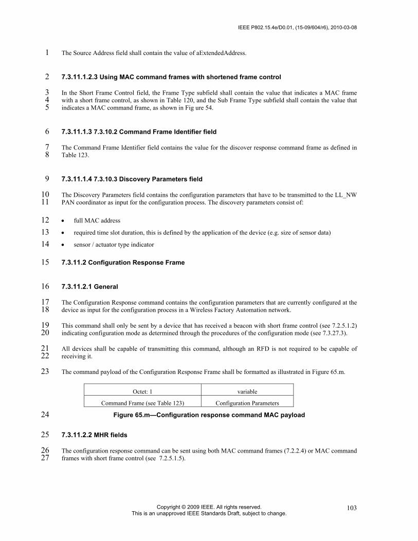
IEEE P802.15.4e/D0.01, (15-09/604/r6), 2010-03-08
Copyright © 2009 IEEE. All rights reserved. This is an unapproved IEEE Standards Draft, subject to change.
103
The Source Address field shall contain the value of aExtendedAddress. 1
7.3.11.1.2.3 Using MAC command frames with shortened frame control 2
In the Short Frame Control field, the Frame Type subfield shall contain the value that indicates a MAC frame 3 with a short frame control, as shown in Table 120, and the Sub Frame Type subfield shall contain the value that 4 indicates a MAC command frame, as shown in Fig ure 54. 5
7.3.11.1.3 7.3.10.2 Command Frame Identifier field 6
The Command Frame Identifier field contains the value for the discover response command frame as defined in 7 Table 123. 8
7.3.11.1.4 7.3.10.3 Discovery Parameters field 9
The Discovery Parameters field contains the configuration parameters that have to be transmitted to the LL_NW 10 PAN coordinator as input for the configuration process. The discovery parameters consist of: 11
• full MAC address 12 • required time slot duration, this is defined by the application of the device (e.g. size of sensor data) 13 • sensor / actuator type indicator 14
7.3.11.2 Configuration Response Frame 15
7.3.11.2.1 General 16
The Configuration Response command contains the configuration parameters that are currently configured at the 17 device as input for the configuration process in a Wireless Factory Automation network. 18
This command shall only be sent by a device that has received a beacon with short frame control (see 7.2.5.1.2) 19 indicating configuration mode as determined through the procedures of the configuration mode (see 7.3.27.3). 20
All devices shall be capable of transmitting this command, although an RFD is not required to be capable of 21 receiving it. 22
The command payload of the Configuration Response Frame shall be formatted as illustrated in Figure 65.m. 23
Octet: 1 variable
Command Frame (see Table 123) Configuration Parameters
Figure 65.m—Configuration response command MAC payload 24
7.3.11.2.2 MHR fields 25
The configuration response command can be sent using both MAC command frames (7.2.2.4) or MAC command 26 frames with short frame control (see 7.2.5.1.5). 27

2010-03-08, (15-09/604/r6), IEEE P802.15.4e/D0.01
Copyright © 2010 IEEE. All rights reserved. This is an unapproved IEEE Standards Draft, subject to change.
104
7.3.11.2.3 Using MAC command frames 1
7.3.11.2.3.1 General 2
The Frame Type subfield of the Frame Control field shall contain the value that indicates a MAC command 3 frame, as shown in Table 120. 4
The Source Addressing Mode subfield of the Frame Control field shall be set to 1 (8-bit short addressing) or 3 5 (64-bit extended addressing). 6
The Source Address field shall contain the value of aVeryShortAddress or aExtendedAddress respectively. 7
7.3.11.2.3.2 Using MAC command frames with short frame control 8
In the Short Frame Control field, the Frame Type subfield shall contain the value that indicates a MAC frame 9 with a short frame control, as shown in Table 120, and the Sub Frame Type subfield shall contain the value that 10 indicates a MAC command frame, as shown in Table 79. 11
7.3.11.2.4 Command Frame Identifier field 12
The Command Frame Identifier field contains the value for the configuration response frame as defined in Table 13 123. 14
7.3.11.2.5 Configuration Parameters field 15
The Configuration Parameters field contains the configuration parameters that are currently configured at the 16 device. The configuration parameters consist of: 17
• full MAC address 18 • short MAC address 19 • required time slot duration, this is defined by the application of the device (e.g. size of sensor data) 20 • sensor / actuator 21 • assigned time slots 22
7.3.11.3 Configuration Request Frame 23
7.3.11.3.1 General 24
The Configuration Request command contains the configuration parameters that the receiving device is requested 25 to use during online mode in a Wireless LL-network. 26
This command shall only be sent by a LL_NW PAN coordinator in response to a received Configuration 27 Response frame of a device during configuration mode. 28
Only LL_NW PAN coordinators are requested to be capable of transmitting this command, RFD are required to 29 be capable of receiving it. 30
The command payload of the Configuration Request Frame shall be formatted as illustrated in Figure 65.n. 31

IEEE P802.15.4e/D0.01, (15-09/604/r6), 2010-03-08
Copyright © 2009 IEEE. All rights reserved. This is an unapproved IEEE Standards Draft, subject to change.
105
Octet: 1 variable
Command Frame Identifier (see Table 82) Configuration Parameters
Figure 65.n—Configuration request command MAC payload 1
7.3.11.3.2 MHR fields 2
7.3.11.3.2.1 General 3
The configuration request command can be sent using both MAC command frames (7.2.2.4) or MAC command 4 frames with shortened frame control 907.2.6.2.6). 5
7.3.11.3.2.2 Using MAC command frames 6
The Frame Type subfield of the Frame Control field shall contain the value that indicates a MAC command 7 frame, as shown in Table 120. 8
The Source Addressing Mode subfield of the Frame Control field shall be set to 1 (8-bit short addressing) or 3 9 (64-bit extended addressing). 10
The Destination Address field shall contain the value of source address of the corresponding Configuration 11 Response frame. 12
7.3.11.3.2.3 Using MAC command frames with short frame control 13
In the Short Frame Control field, the Frame Type subfield shall contain the value that indicates a MAC frame 14 with a short frame control, as shown in Table 120, and the Sub Frame Type subfield shall contain the value that 15 indicates a MAC command frame, as shown in Table 79. 16
7.3.11.3.3 Command Frame Identifier field 17
The Command Frame Identifier field contains the value for the configuration response frame as defined in Table 18 123. 19
7.3.11.3.4 Configuration Parameters field 20
The Configuration Parameters field contains the new configuration parameters that are sent to the device in order 21 to (re-)configure it. The configuration parameters consist of: 22
• full MAC address 23 • short MAC address 24 • transmission channel 25 • existence of management frames 26 • time slot duration 27 • assigned time slots 28

2010-03-08, (15-09/604/r6), IEEE P802.15.4e/D0.01
Copyright © 2010 IEEE. All rights reserved. This is an unapproved IEEE Standards Draft, subject to change.
106
7.3.11.4 Clear to Send (CTS) Shared Group Frame 1
7.3.11.4.1 General 2
The Clear to Send Shared Group command indicates to the devices of the star network that they now may use the 3 time slot for transmitting their own data with a simplified CSMA/CA. 4
This command shall only be sent by a LL_NW PAN coordinator in a time slot after tSlotTxOwner has been 5 elapsed and the slot owner is not transmitting. 6
Only LL_NW PAN coordinators shall be capable of transmitting this command, all other devices shall be 7 capable of receiving it. 8
The command payload of the Clear to Send Shared Group frame shall be formatted as illustrated in Figure 65.o. 9
Octet: 1 1
Command Frame Identifier (see Table 82) Network ID
Figure 65.o—Clear to send shared group command MAC payload 10
7.3.11.4.2 MHR fields 11
The clear to send shared group command shall be sent using MAC command frames with short frame control. 12
In the Short Frame Control field, the Frame Type subfield shall contain the value that indicates a MAC frame 13 with a shortened frame control, as shown in Table 120, and the Sub Frame Type subfield shall contain the value 14 that indicates a MAC command frame, as shown in Table 79. 15
7.3.11.4.3 Command Frame Identifier field 16
The Command Frame Identifier field contains the value for the clear to send shared group frame as defined in 17 Table 123. 18
7.3.11.4.4 Network ID field 19
The Network ID field contains an identifier specific to the LL_NW PAN coordinator. 20
7.3.11.5 Request to Send (RTS) Frame 21
7.3.11.5.1 General 22
The Request to Send command may be used by a device to indicate to the LL_NW PAN coordinator and to the 23 other devices of the star network that it wants to transmit data with a simplified CSMA/CA. The request to send 24 frame is transmitted using a simplified CSMA/CA. 25
This command shall only be sent by a device in a time slot after tSlotOwner has been elapsed and a clear to send 26 shared group frame has been received from the LL_NW PAN coordinator. 27
Devices shall be capable of transmitting and receiving this command. 28

IEEE P802.15.4e/D0.01, (15-09/604/r6), 2010-03-08
Copyright © 2009 IEEE. All rights reserved. This is an unapproved IEEE Standards Draft, subject to change.
107
The command payload of the Request to Send frame shall be formatted as illustrated in Figure 65.p. 1
Octet: 1 1 1
Command Frame Identifier (see Table 82) Short Originator Address Network ID
Figure 65.p—Request to send command MAC payload 2
7.3.11.5.2 MHR fields 3
The request to send command can be sent using MAC command frames with shortened frame control. 4
In the Short Frame Control field, the Frame Type subfield shall contain the value that indicates a MAC frame 5 with a short frame control, as shown in Table 120, and the Sub Frame Type subfield shall contain the value that 6 indicates a MAC command frame, as shown in Table 79. 7
7.3.11.5.3 Command Frame Identifier field 8
The Command Frame Identifier field contains the value for the request to send frame as defined in Table 123. 9
7.3.11.5.4 Short Originator Address 10
The Short Originator Address field contains the 1-octet short address of the device sending this request to send 11 frame. 12
7.3.11.5.5 Network ID field 13
The Network ID field contains an identifier specific to the LL_NW PAN coordinator. It has to be identical to the 14 Network ID of the corresponding received CTS shared group frame. 15
7.3.11.6 Clear to Send (CTS) Frame 16
7.3.11.6.1 General 17
The Clear to Send command indicates to a specific device of the star network that it may now use the time slot 18 for transmitting its own data with a simplified CSMA/CA. 19
This command shall only be sent by a LL_NW PAN coordinator in a time slot after tSlotOwner has been elapsed 20 and the slot owner is not transmitting. 21
The LL_NW PAN coordinators shall be capable of transmitting this command, other LL devices shall be capable 22 of receiving it. 23
The command payload of the Clear to Send Shared Group frame shall be formatted as illustrated in Figure 65.q. 24
Octet: 1 1 1
Command Frame Identifier (see Table 82) Short Destinatioon Address Network ID
Figure 65.q—Clear to send command MAC payload 25

2010-03-08, (15-09/604/r6), IEEE P802.15.4e/D0.01
Copyright © 2010 IEEE. All rights reserved. This is an unapproved IEEE Standards Draft, subject to change.
108
7.3.11.6.2 MHR fields 1
The clear to send command can be sent using MAC command frames with short frame control. 2
In the Short Frame Control field, the Frame Type subfield shall contain the value that indicates a MAC frame 3 with a short frame control, as shown in Table 120, and the Sub Frame Type subfield shall contain the value that 4 indicates a MAC command frame, as shown in Table 79. 5
6
7.3.11.6.3 Command Frame Identifier field 7
The Command Frame Identifier field contains the value for the clear to send shared group frame as defined in 8 Table 123. 9
7.3.11.6.4 Short Destination Address 10
The Short Destination Address field contains the 1-octet short address of the device to which this clear to send 11 frame is directed. 12
7.3.11.6.5 Network ID field 13
The Network ID field contains an identifier specific to the LL_NW PAN coordinator which shall be identical to 14 the Network ID of the corresponding received RTS frame. 15
7.3.12 DSME-commands 16
7.3.12.1 General 17
Subclause 7.3 applies in addition. 18
7.3.12.2 DSME-Association request command 19
7.3.12.2.1 General 20
Subclause 7.3.1 applies in addition but the association request command shall be formatted as illustrated in 21 Figure 65.r. 22
octets: (see 7.2.2.4) 1 1 1
MHR fields Command Frame Identifier (see Table 82) Capability Information Channel Offset
Figure 65.r—Association request command format 23
7.3.12.2.2 MHR fields 24
Subclause 7.3.1.1 applies. 25

IEEE P802.15.4e/D0.01, (15-09/604/r6), 2010-03-08
Copyright © 2009 IEEE. All rights reserved. This is an unapproved IEEE Standards Draft, subject to change.
109
7.3.12.2.3 Capability Information field 1
Subclause 7.3.1.2 applies but the Capability Information field shall be formatted as illustrated in Figure 65.s. 2
bits: 0 1 2 3 4 5 6 7 Alternate PAN Coordinator
Device Type
Power Source
Receiver On When Idle
Channel Sequence Request
Reserved Security Capability
Allocate Address
Figure 65.s—DSME-Capability Information field format 3 The Channel Sequence Request subfield is 1 bit in length and shall be set to one if the PAN runs in both beacon-4 enabled mode and Channel Hopping mode. 5
7.3.12.2.4 Channel Offset field 6
The Channel Offset field is 8 bits in length and shall be set to the offset value of the unassociated device that 7 wished to associate with a PAN, this value is specified by the next higher layer. 8
7.3.12.3 DSME-Association respond command 9
7.3.12.3.1 General 10
Subclause 7.3.2 applies in addition but the DSME-Association respond command shall be formatted as illustrated 11 in Figure 65.t. 12
octets: (see 7.2.2.4) 1 2 1 1 Variable
MHR fields Command Frame Identifier (see Table 82)
Short Address
Association Status
Channel Hopping Sequence Length
Channel Hopping Sequence
Figure 65.t—DSME-Association response command format 13
7.3.12.3.2 MHR fields 14
Subclause 7.3.2.1 applies. 15
7.3.12.3.3 Short Address field 16
Subclause 7.3.2.2 applies. 17
7.3.12.3.4 Association Status field 18
Subclause 7.3.2.3 applies. 19
7.3.12.3.5 Channel Hopping Sequence Length field 20
The Channel Hopping Sequence Length field is 8 bits in length and shall specify the length of the channel 21 hopping sequence used in the PAN if the PAN runs in both beacon-enabled mode and Channel Hopping mode. 22

2010-03-08, (15-09/604/r6), IEEE P802.15.4e/D0.01
Copyright © 2010 IEEE. All rights reserved. This is an unapproved IEEE Standards Draft, subject to change.
110
7.3.12.3.6 Channel Hopping Sequence field 1
The size of the Channel Hopping Sequence subfield is defined by the Channel Hopping Sequence Length 2 subfield and the Channel Hopping Sequence field specifies the channel hopping sequence used in the PAN, if the 3 PAN runs in both beacon-enabled mode and Channel Hopping mode. 4
7.3.12.4 DSME handshake command 5
7.3.12.4.1 General 6
The DSME handshake command is used by an associated device to request the allocation of a new DSME or the 7 deallocation, reallocation, or change of an existing DSME from the corresponding device. Only devices that have 8 a 16-bit short address less than 0xfffe shall send this command. 9
This command is mandatory for DSME-devices. 10
The DSME request command shall be formatted as illustrated in Figure 65.u. 11
octets: (see 7.2.2.4) 1 Variable MHR fields Command Frame Identifier (see Table 82) DSME Characteristics
Figure 65.u—DSME handshake command format 12
7.3.12.4.2 DSME-MHR fields 13
The Destination Addressing Mode and the Source Addressing Mode subfields of the Frame Control field shall 14 both be set to two (i.e., 16-bit short addressing). 15
The Frame Pending subfield of the Frame Control field shall be set to zero and ignored upon reception, and the 16 Acknowledge Request subfield shall be set to one. 17
The Source PAN Identifier field shall contain the value of macPANId, and the Source Address field shall contain 18 the value of macShortAddress. 19
For the DSME handshake request command frame, the Destination PAN Identifier field shall contain the 20 identifier of the PAN to which to request for DSME, and the Destination Address field shall contain the address 21 of the Destination device to which the DSME request command frame is being sent. For the DSME handshake 22 reply/notify command frame, the Destination PAN Identifier field shall be set to 0xffff (e.g., broadcast PAN 23 identifier), and the Destination Address field shall be set to 0xffff. 24
7.3.12.4.3 DSME Characteristics fields 25
The DSME Characteristics field shall be formatted as illustrated in Figure 65.v. 26
bit: 0 1-8 9 10-12 13-14 15 16-55 variable Channel DiversityMode
DSME Length
DSME Direction
DSME Characteristics Type
DSME Handshake Type
Prioritized Channel Access
DSME Descriptor
DSME ABT Specification
Figure 65.v—DSME Characteristics field format 27 The ChannelDiversityMode subfield is 1 bit in length and shall be set to one of the non-reserved values listed in 28 Table 84.a. 29

IEEE P802.15.4e/D0.01, (15-09/604/r6), 2010-03-08
Copyright © 2009 IEEE. All rights reserved. This is an unapproved IEEE Standards Draft, subject to change.
111
Table 84.a—Values of the Channel Diversity Mode subfield 1 Channel Diversity Mode value
b0 Description
0 Channel Adaptation mode 1 Channel Hopping mode
2 The DSME Length subfield is 8 bits in length and shall contain the number of superframe slots being requested 3 for the DSME. 4
The DSME Direction subfield is 1 bit in length and shall indicate the direction of the DSME handshake 5 command. 6
The DSME Characteristics Type subfield is 3 bits in length and shall be set to one of the non-reserved values 7 listed in Table 84.b. 8
Table 84.b—Values of the DSME Characteristics Type subfield 9 DSME Characteristics Type value
b2b1b0 Description
000 Deallocation 001 Allocation 010 Reallocation 011 Duplicated Allocation Notification 100 Robust DSME Allocation 101 Reduce 110 Restart 111 Reserved
10 The DSME Handshake Type subfield is 2 bits in length and shall be set to one of the non-reserved values listed 11 in Table 84.c. 12
Table 84.c—Values of the DSME Handshake Type subfield 13 DSME Handshake Type value
b1b0 Description
00 Request
01 Reply
10 Notify
11 Reserved
14 The Prioritized Channel Access subfield is 1 bit in length and shall be set to one if DSME should be reserved as 15 high priority, or set to zero if DSME should be reserved as low priority. When the DSME request command is 16 used in the DSME change procedure, the Prioritized Channel Access shall be set according to the original 17 DSME. 18
7.3.12.4.4 DSME Descriptor field 19
The DSME Descriptor field is 5 octets in length and shall be formatted as illustrated in Figure 65.w. 20
bit: 0-15 16-31 32-39 Destination Address DSME slot identifier DSME Length
Figure 65.w—Format of the DSME Descriptor field 21
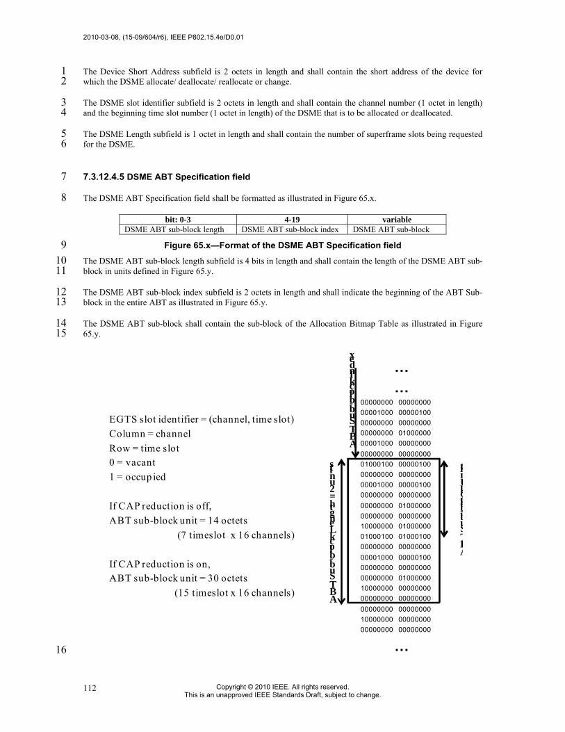
2010-03-08, (15-09/604/r6), IEEE P802.15.4e/D0.01
Copyright © 2010 IEEE. All rights reserved. This is an unapproved IEEE Standards Draft, subject to change.
112
The Device Short Address subfield is 2 octets in length and shall contain the short address of the device for 1 which the DSME allocate/ deallocate/ reallocate or change. 2
The DSME slot identifier subfield is 2 octets in length and shall contain the channel number (1 octet in length) 3 and the beginning time slot number (1 octet in length) of the DSME that is to be allocated or deallocated. 4
The DSME Length subfield is 1 octet in length and shall contain the number of superframe slots being requested 5 for the DSME. 6
7.3.12.4.5 DSME ABT Specification field 7
The DSME ABT Specification field shall be formatted as illustrated in Figure 65.x. 8
bit: 0-3 4-19 variable DSME ABT sub-block length DSME ABT sub-block index DSME ABT sub-block
Figure 65.x—Format of the DSME ABT Specification field 9 The DSME ABT sub-block length subfield is 4 bits in length and shall contain the length of the DSME ABT sub-10 block in units defined in Figure 65.y. 11
The DSME ABT sub-block index subfield is 2 octets in length and shall indicate the beginning of the ABT Sub-12 block in the entire ABT as illustrated in Figure 65.y. 13
The DSME ABT sub-block shall contain the sub-block of the Allocation Bitmap Table as illustrated in Figure 14 65.y. 15
EGTS slot identifier = (channel, time slot)Column = channelRow = time slot0 = vacant1 = occup ied
If CAP reduction is off,ABT sub-block unit = 14 octets
(7 timeslot x 16 channels)
If CAP reduction is on,ABT sub-block unit = 30 octets
(15 timeslot x 16 channels)
……
00000000 00000000 00001000 0000010000000000 0000000000000000 0100000000001000 0000000000000000 0000000001000100 0000010000000000 00000000 00001000 0000010000000000 0000000000000000 0100000000000000 0000000010000000 0100000001000100 0100010000000000 00000000 00001000 0000010000000000 0000000000000000 0100000010000000 0000000000000000 0000000000000000 00000000 10000000 0000000000000000 00000000
…
ABT Sub-block Length = 2 units
ABT Sub-block Index
ABTSub-blockUnit
16
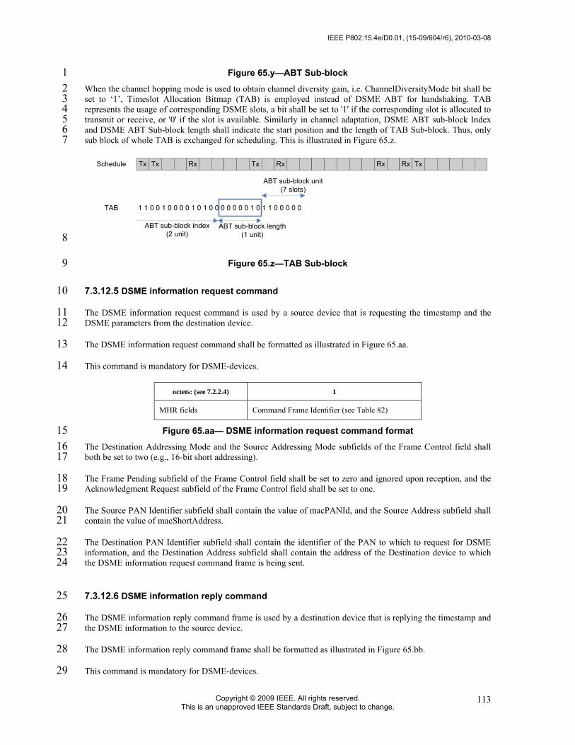
IEEE P802.15.4e/D0.01, (15-09/604/r6), 2010-03-08
Copyright © 2009 IEEE. All rights reserved. This is an unapproved IEEE Standards Draft, subject to change.
113
Figure 65.y—ABT Sub-block 1 When the channel hopping mode is used to obtain channel diversity gain, i.e. ChannelDiversityMode bit shall be 2 set to ‘1’, Timeslot Allocation Bitmap (TAB) is employed instead of DSME ABT for handshaking. TAB 3 represents the usage of corresponding DSME slots, a bit shall be set to '1' if the corresponding slot is allocated to 4 transmit or receive, or '0' if the slot is available. Similarly in channel adaptation, DSME ABT sub-block Index 5 and DSME ABT Sub-block length shall indicate the start position and the length of TAB Sub-block. Thus, only 6 sub block of whole TAB is exchanged for scheduling. This is illustrated in Figure 65.z. 7
Tx Tx Rx Tx Rx Rx Rx Tx
1 1 0 0 1 0 0 0 0 1 0 1 0 0 0 0 0 0 0 1 0 1 1 0 0 0 0 0
Schedule
TAB
ABT sub-block index(2 unit)
ABT sub-block length(1 unit)
ABT sub-block unit(7 slots)
8
Figure 65.z—TAB Sub-block 9
7.3.12.5 DSME information request command 10
The DSME information request command is used by a source device that is requesting the timestamp and the 11 DSME parameters from the destination device. 12
The DSME information request command shall be formatted as illustrated in Figure 65.aa. 13
This command is mandatory for DSME-devices. 14
octets: (see 7.2.2.4) 1
MHR fields Command Frame Identifier (see Table 82)
Figure 65.aa— DSME information request command format 15 The Destination Addressing Mode and the Source Addressing Mode subfields of the Frame Control field shall 16 both be set to two (e.g., 16-bit short addressing). 17
The Frame Pending subfield of the Frame Control field shall be set to zero and ignored upon reception, and the 18 Acknowledgment Request subfield of the Frame Control field shall be set to one. 19
The Source PAN Identifier subfield shall contain the value of macPANId, and the Source Address subfield shall 20 contain the value of macShortAddress. 21
The Destination PAN Identifier subfield shall contain the identifier of the PAN to which to request for DSME 22 information, and the Destination Address subfield shall contain the address of the Destination device to which 23 the DSME information request command frame is being sent. 24
7.3.12.6 DSME information reply command 25
The DSME information reply command frame is used by a destination device that is replying the timestamp and 26 the DSME information to the source device. 27
The DSME information reply command frame shall be formatted as illustrated in Figure 65.bb. 28
This command is mandatory for DSME-devices. 29

2010-03-08, (15-09/604/r6), IEEE P802.15.4e/D0.01
Copyright © 2010 IEEE. All rights reserved. This is an unapproved IEEE Standards Draft, subject to change.
114
octets: (see 7.2.2.4) 1 3 variable
MHR fields Command Frame Identifier (see Table 82)
Timestamp DSME Characteristics (see 7.3.12.4.3)
Figure 65.bb—DSME information reply command format 1 The Destination Addressing Mode and the Source Addressing Mode subfields of the Frame Control field shall 2 both be set to two (e.g., 16-bit short addressing). 3
The Frame Pending subfield of the Frame Control field shall be set to zero and ignored upon reception, and the 4 Acknowledgment Request subfield of the Frame Control field shall be set to one. 5
The Source PAN Identifier subfield shall contain the value of macPANId, and the Source Address subfield shall 6 contain the value of macShortAddress. 7
The Destination PAN Identifier subfield shall contain the identifier of the PAN to which to reply the DSME 8 information, and the Destination Address subfield shall contain the address of the Destination device to which 9 request the DSME information. 10
7.3.12.7 DSME-Beacon allocation notification command 11
The beacon allocation notification command is used by a device that selects vacant Superframe Duration (SD) 12 for using transmission of beacon frame. 13
The beacon allocation notification command shall be formatted as illustrated in Figure 65.cc. 14
This command is mandatory for DSME-devices. 15
octets: (see 7.2.2.4) 1 2 MHR fields Command Frame Identifier
(see Table 82) Allocation Beacon SD Index
Figure 65.cc—Beacon allocation notification command format 16 The Destination Addressing Mode and Source Addressing Mode subfields of the Frame Control field shall both 17 be set to two (e.g., 16-bit short addressing). 18
The Frame Pending subfield of the Frame Control field shall be set to zero and ignored upon reception, and the 19 Acknowledgment Request subfield shall be set to zero. 20
The PAN ID Compression subfield of the Frame Control field shall be set to one. In accordance with this value 21 of the PAN ID Compression subfield, the Destination PAN Identifier field shall contain the value of macPANId, 22 while the Source PAN Identifier field shall be omitted. The Destination Address field shall be set to 0xffff. The 23 Source Address field shall contain the value of macShortAddress. 24
The Allocation Beacon SD Index field is 2 octets in length and shall contain the allocating SD index number for 25 beacon frame which is allocated to the Source device. 26
27
7.3.12.8 DSME-Beacon collision notification command 28
The beacon collision notification command is used by a device that detects the collision of beacon frame. 29
The beacon collision notification command shall be formatted as illustrated in Figure 65.dd. 30

IEEE P802.15.4e/D0.01, (15-09/604/r6), 2010-03-08
Copyright © 2009 IEEE. All rights reserved. This is an unapproved IEEE Standards Draft, subject to change.
115
This command is mandatory for DSME-devices. 1
octets: (see 7.2.2.4) 1 2 MHR fields Command Frame Identifier
(see Table 82) Collision SD Index
Figure 65.dd—Beacon collision notification command format 2 The Destination Addressing Mode and Source Addressing Mode subfields of the Frame Control field shall both 3 be set to two (e.g., 16-bit short addressing). 4
The Frame Pending subfield of the Frame Control field shall be set to zero and ignored upon reception, and the 5 Acknowledgment Request subfield shall be set to one. 6
The PAN ID Compression subfield of the Frame Control field shall be set to one. In accordance with this value 7 of the PAN ID Compression subfield, the Destination PAN Identifier field shall contain the value of macPANId, 8 while the Source PAN Identifier field shall be omitted. The Destination Address field shall be set to 0xffff. The 9 Source Address field shall contain the value of macShortAddress. 10
The Conflict SD Index field is 2 octets in length and shall contain the SD index number of collision beacon 11 frame. 12
7.3.12.9 DSME-Link status report command 13
7.3.12.9.1 General 14
The link status report command allows a source device to report its link quality parameters to a destination 15 device. 16
This command shall only be sent by an associated device that wishes to report the link quality. All devices shall 17 be capable of transmitting this command, although an RFD is not required to be capable of receiving it. 18
The link status report command shall be formatted as illustrated in Figure 65.ee. 19
octets: (see 7.2.2.4) 1 variable MHR fields Command Frame Identifier (see Table 82) Link Status Specification
Figure 65.ee—Link status report command format 20 The Link Status Specification fields shall be formatted as illustrated in Figure 65.ff. 21
octets: 1 variable Link Status Descriptor Count Link Status List
Figure 65.ff—Link status specification field format 22
7.3.12.9.2 MHR fields 23
The Source Addressing Mode subfield of the Frame Control field shall be set to two (16-bit extended 24 addressing), and the Destination Addressing Mode subfield shall be set to the same mode as the destination 25 device to which the status report command refers. 26
The Frame Pending subfield of the Frame Control field shall be set to one, and the Acknowledgment Request 27 subfield shall be set to one. 28

2010-03-08, (15-09/604/r6), IEEE P802.15.4e/D0.01
Copyright © 2010 IEEE. All rights reserved. This is an unapproved IEEE Standards Draft, subject to change.
116
The Destination PAN Identifier field shall contain the identifier of the PAN of the destination device to which to 1 report the link status. The Destination Address field shall contain the address of the destination device to which 2 the status report command is being sent. 3
The Source PAN Identifier field shall contain the value of macPANId, and the Source Address field shall contain 4 the value of macShortAddress. 5
The Frame Type subfield in MHR shall be set to 100 and the Frame Version subfield should be set to 0x10. 6
7.3.12.9.3 Link Status Descriptor Count field 7
The Link Status Descriptor Count field is 1 octet in length and specifies the number of the Link Status 8 Descriptors in the link status List field. 9
7.3.12.9.4 Link Status List fields 10
The size of the Link Status List fields is defined by the values specified in the Link Status Descriptor Count field 11 and contain the list of Link Status Descriptors that represents the link status of each link. The Link Status 12 Descriptor shall be formatted as illustrated in Figure 65.gg. 13
octets: 1 1 1 1 Channel avgLQI avgRSSI Reserved
Figure 65.gg—Link status Descriptor format 14 The Channel subfield is 1 octet in length and specifies the channel index reported by the source device. 15
The avgLQI subfield is 1 octet in length and contains the average received LQI of the channel specified in 16 Channel subfield within LinkStatusStatisticPeriod symbols. 17
The avgRSSI subfield is 1 octet in length and contains the average received signal power by ED measurement 18 during a period of LinkStatusStatisticPeriod symbols. The avgRSSI measurement shall be performed for each 19 received packet, and the use of the avgRSSI result by the next higher layer is not specified in this standard. 20
7.3.12.10 DSME-Multi-channel beacon request command 21
The multi-channel beacon request command is used by a device that is performing asymmetric multi-channel 22 active scan. 23
The multi-channel beacon request command shall be formatted as illustrated in Figure 65.hh. This command is 24 mandatory for DSME-devices. 25
octets: (see 7.2.2.4) 1 4 MHR fields Command Frame Identifier (see Table 82) Scan Channels
Figure 65.hh—Multi-channel beacon request command format 26 The Destination Addressing Mode subfield of the Frame Control field shall be set to two (e.g., 16-bit short 27 addressing), and the Source Addressing Mode subfield shall be set to zero (e.g., source addressing information 28 not present). 29
The Frame Pending subfield of the Frame Control field shall be set to zero and ignored upon reception, and the 30 Acknowledgment Request subfield shall be set to zero. 31
The Destination PAN Identifier subfield shall contain the broadcast PAN identifier (i.e., 0xffff). The Destination 32 Address subfield shall contain the broadcast short address (i.e., 0xffff). 33

IEEE P802.15.4e/D0.01, (15-09/604/r6), 2010-03-08
Copyright © 2009 IEEE. All rights reserved. This is an unapproved IEEE Standards Draft, subject to change.
117
The Scan Channels subfield is represented in 27-bit bitmaps. The 27 bits (b0, b1,... b26) indicate which channels 1 are to be scanned (1 = scan, 0 = do not scan) for each of the 27 channels supported by the ChannelPage 2 parameter. 3
7.3.12.11 DSME-Multi-channel hello command 4
7.3.12.11.1 General 5
The multi-channel hello command is used to inform neighboring devices of the device’s designated channel. 6
The multi-channel beacon request command shall be formatted as illustrated in Figure 65.ii. This command is 7 mandatory for DSME-devices. 8
octets: (see 7.2.2.4) 1 1 MHR fields Command Frame Identifier (see Table 82) Hello Specification
Figure 65.ii—Multi-channel hello command format 9
7.3.12.11.2 MHR fields 10
The Destination Addressing Mode subfield of the Frame Control field shall be set to two (e.g., 16-bit short 11 addressing), and the Source Addressing Mode subfield shall be set to zero (e.g., source addressing information 12 not present). 13
The Frame Pending subfield of the Frame Control field shall be set to zero and ignored upon reception, and the 14 Acknowledgment Request subfield shall be set to zero. 15
The Destination PAN Identifier subfield shall contain the broadcast PAN identifier (i.e., 0xffff). The Destination 16 Address subfield shall contain the broadcast short address (i.e., 0xffff). 17
7.3.12.11.3 Hello Specification field 18
The Hello Specification field shall be formatted as illustrated in Figure 65.jj. 19
bits: 5 1 2 Designated Channel Index Hello Reply Request Reserved
Figure 65.jj—Hello specification field format 20 The Designated Channel Index subfield is 5 bits in length and shall contain the designated logical channel index 21 number of the device. 22
The Hello Reply Request subfield is 1 bit in length and shall indicate whether the multi-channel hello command 23 needs a hello reply. If the Hello Reply Request bit is set to’1’, the device shall transmit a hello reply upon 24 receiving the hello command. 25
7.3.12.12 DSME-Multi-channel hello reply command 26
The multi-channel hello reply command is used to 27
TBD ... 28 The multi-channel beacon request command shall be formatted as illustrated in Figure 65Q. 29

2010-03-08, (15-09/604/r6), IEEE P802.15.4e/D0.01
Copyright © 2010 IEEE. All rights reserved. This is an unapproved IEEE Standards Draft, subject to change.
118
TBD … 1 2
7.3.12.13 DSME-Channel probe command 3
7.3.12.13.1 General 4
The channel probe command is used to check the link quality of the specified channel. 5
The channel probe command shall be formatted as illustrated in Figure 65.kk. This command is mandatory for 6 DSME-device. 7
octets: (see 7.2.2.4) 1 2 MHR fields Command Frame Identifier (see Table 82) Channel Probe Specification
Figure 65.kk—Channel probe command format 8
7.3.12.13.2 MHR fields 9
The Source Addressing Mode subfield of the Frame Control field shall be set to two (16-bit extended 10 addressing), and the Destination Addressing Mode subfield shall be set to the same mode as the destination 11 device to which the channel probe command refers. 12
The Frame Pending subfield of the Frame Control field shall be set to zero, and the Acknowledgment Request 13 subfield shall be set to one. 14
The Destination PAN Identifier field shall contain the identifier of the PAN of the destination device to which to 15 check the link quality. The Destination Address field shall contain the address of the destination device to which 16 the channel probe command is being sent. 17
The Source PAN Identifier field shall contain the value of macPANId, and the Source Address field shall contain 18 the value of macShortAddress. 19
7.3.12.13.3 Channel Probe Specification field 20
The Channel Probe Specification field shall be formatted as illustrated in Figure 65.ll. 21
bits: 2 5 5 4 Channel Probe Subtype Designated Channel Probe Channel Reserved
Figure 65.ll—Channel Probe specification format 22 The Channel Probe Subtype subfield is 2 bits in length and shall be set to one of the non-reserved values listed in 23 Table 84.d. 24

IEEE P802.15.4e/D0.01, (15-09/604/r6), 2010-03-08
Copyright © 2009 IEEE. All rights reserved. This is an unapproved IEEE Standards Draft, subject to change.
119
Table 84.d—Values of the Channel Probe Subtype subfield 1 Channel Probe subtype value
b1b0 Description
00 Request 01 Reply 10 Probe 11 Reserved
2 The Designated Channel subfield is 5 bits in length and indicates the originator’s designated channel. 3
The Probe Channel subfield is 5 bits in length and indicates the channel that needs to be probed. 4
7.3.13 EBR-commands 5
7.3.13.1 EBR-Enhanced Beacon request command 6
7.3.13.1.1 General 7
The enhanced beacon request command is intended to be used by a EBR-device to locate a subset of all 8 coordinators within its POS during an active scan. 9
This command is optional for an FFD and an RFD. 10
The enhanced beacon request command shall be formatted as illustrated in Figure 65.mm. 11
Octets:7 1 1 0/1 0/1 Variable
MHR fields Command Frame Identifier (see Table 82)
Request Field
Link Quality Percent filter
Extended Payload
Figure 65.mm—EBR-Enhanced Beacon request command 12 The Destination Addressing Mode subfield of the Frame Control field shall be set to two (i.e., 16-bit short 13 addressing), and the Source Addressing Mode subfield shall be set to zero (i.e., source addressing information 14 not present). 15
The Frame Pending subfield of the Frame Control field shall be set to zero and ignored upon reception. 16
The Acknowledgment Request subfield and Security Enabled subfield shall be set to zero. If the enhanced 17 beacon request is being sent on a particular PAN Identifier that is not the broadcast PAN identifier the Security 18 Enable subfield may be set to 1, otherwise it shall be set to 0. 19
The Destination PAN Identifier field shall contain the any appropriate PAN identifier. If the broadcast PAN 20 identifier is used, any device may respond however if a specific PAN identifier is used only devices using that 21 PAN identifier will respond to the enhanced beacon request. 22
The Destination Address field shall contain the broadcast short address (i.e., 0xffff). 23

2010-03-08, (15-09/604/r6), IEEE P802.15.4e/D0.01
Copyright © 2010 IEEE. All rights reserved. This is an unapproved IEEE Standards Draft, subject to change.
120
7.3.13.1.2 Request Field 1
7.3.13.1.2.1 General 2
The request field is a 1 octet field indicating what optional request discriminators are included in the Enhanced 3 Beacon Request Command Payload. The Request Field is as shown in Table 84.e. 4
Table 84.e—Request field coding 5
Bit SubField
0 Permit Joining On
1 LinkQuality
2 Percent filter
3 - 6 Reserved
7 Extended Payload
6 For any bits set in the request field the following is done. 7
7.3.13.1.2.2 Permit Joining On 8
Only devices with permit joining on shall respond to the enhanced beacon request. 9
7.3.13.1.2.3 LinkQuality Level 10
Following the Request field the enhanced beacon request will include a field containing a value for LinkQuality. 11 The device will respond to the enhanced beacon request if the MCPS-DATA.indication indicates a 12 mpduLinkQuality equal or lower than this value (where lower values represent higher quality links). 13
7.3.13.1.2.4 Percent filter 14
Following the Request Field a byte will be included of a scaled value from 0x00 to 0x64 representing zero to 100 15 percent probability for a given device to respond to the enhanced beacon request. The device will then randomly 16 determine if it is to respond to the enhanced beacon request based on meeting this probability. For example if the 17 probability is set to 10% then 1 of 10 devices would randomly be expected to respond. 18
7.3.13.1.2.5 Extended Payload 19
If this bit is set the extended payload field shall be included in the enhanced beacon request. The extended 20 payload should be provided as the MSDU in the MCPS-DATA.indication to the local SSCS entity in which case 21 the SSCS entity would be responsible for handling beacon responses based on data in this extended payload. 22

IEEE P802.15.4e/D0.01, (15-09/604/r6), 2010-03-08
Copyright © 2009 IEEE. All rights reserved. This is an unapproved IEEE Standards Draft, subject to change.
121
7.3.14 LE-commands 1
7.3.14.1 RIT data request command 2
7.3.14.1.1 General 3
The RIT data request command allows a device to request data from its neighboring devices in the RIT mode. 4 This command shall only be sent and received in the RIT mode (macRitPeriod : non zero value). This command 5 is optional and applicable for FFD only. The RIT data request command shall be formatted as illustrated in 6 Figure 65.nn. 7
Octets : (see 7.2.2.4) 1 0 or 4 MHR fields Command Frame Identifier
(see Table 82) Optional command payload
Figure 65.nn— Format of RIT data request command 8
7.3.14.1.2 MHR fields 9
The Frame Pending subfield of the Frame Control field shall be set to zero and ignored upon reception, and the 10 Acknowledgement Request subfield shall also be set to zero. All other subfields shall be set appropriately 11 according to the intended use of the command frame. 12
7.3.14.1.3 Command Frame Identifier 13
See Table 82. 14
7.3.14.1.4 Optional Command Payload 15
The command payload can be either 0 or 4 octets. The 4-octet payload is defined in Figure 65.oo: 16
Octets : 1 1 2 Time to 1st Listen (T0) Number of Repeat (N) Repeat Listen Interval (T)
Figure 65.oo— Format of Optional Command Payload 17 Time to 1st Listen (T0) and Repeat Listen Interval (T) are in the same unit as macRitPeriod. Number of 18 Repeat Listen (N) is constrained by T0 + N*T < macRitPeriod. 19
7.3.14.2 Wake-up frame 20
7.3.14.2.1 General 21
The wake-up frame shall be formatted as illustrated in Figure 65.pp 22

2010-03-08, (15-09/604/r6), IEEE P802.15.4e/D0.01
Copyright © 2010 IEEE. All rights reserved. This is an unapproved IEEE Standards Draft, subject to change.
122
octets: 1 1 4 0/5/6/10/14 2 variable 0/2
sFCF Sequence number Addressing fields
Auxiliary Security Header
RZ time Frame payload FCS
MHR MAC payload MFR
Figure 65.pp—Format of Optional Command Payload 1 The order of the fields of the wake-up frame shall conform to the order of the general MAC frame as 2 illustrated in Figure 43. 3
7.3.14.2.2 Wake-up frame MHR fields 4
The MHR for a wake-up frame shall contain the Short Frame Control Field, the Sequence Number Field, 5 the Destination PAN Id, and the Destination Address field. 6
In the Short Frame Control Field, the Frame Type shall contain the value that indicates a wake-up frame, as 7 shown in Table {xxx}. If protection is used for the wake-up frame, the Security Enabled subfield shall be 8 set to one. The Frame Version subfield of the Short Frame Control Field shall be set to the value zero. 9
The Sequence Number field shall be set to the current value of macDSN. 10
The addressing fields shall comprise only the destination addressing fields. The Destination PAN Identifier 11 and the Destination Address fields shall contain the PAN Identifier and the short address of the device 12 receiving the wake-up frame. 13
7.3.14.2.3 Wake-up frame RZ time field 14
The wake-up frame payload field is two octets in length and specifies the Rendezvous Time (RZTime), 15 which is the expected length of time in units of 10 symbols between the end of the transmission of the 16 wakeup frame and the beginning of the transmission of the payload frame. The RZ Time shall be set by the 17 next higher layer when requesting the MAC sublayer to transmit. The last wakeup frame in a wakeup 18 sequence shall have RZTime set to the value zero..Wake-up frame payload field 19
The wake-up frame payload field is an optional field specified to be transmitted in the wake-up frame. 20
NOTE—Inclusion of this field is determined via inspection of the Frame Length subfield of the PHY header field of 21 the PPDU and the other frame fields. 22
7.3.15 RFID-commands 23
7.3.15.1 RFID Blink commands 24
7.3.15.1.1 General 25
The RFID Blink commands indicate to the PAN coordinator the identifier of an RFID which is the source. 26
This command shall only be sent or processed by a device with both macRFIDcapable and macRFIDenabled set 27 to TRUE. 28

IEEE P802.15.4e/D0.01, (15-09/604/r6), 2010-03-08
Copyright © 2009 IEEE. All rights reserved. This is an unapproved IEEE Standards Draft, subject to change.
123
Only PAN coordinators are requested to be capable of recieving this command, devices are required to be 1 capable of transmitting it. 2
The command payload of the RFID Blink frames shall be formatted as illustrated in Figure 65.qq. 3
4
Figure 65.qq—RFID Blink commands MAC payload 5
7.3.15.1.2 MHR fields 6
The RFID Blink commands can be sent using MAC command frames with the short frame control (see Figure 7 42.b. 8
In the Short Frame Control field, the Frame Type subfield shall contain the value that indicates a MAC frame 9 with a short frame control, as shown in Table 79, and the Sub Frame Type subfield shall contain the value that 10 indicates a MAC command frame, as shown in Table 79. 11
7.3.15.1.3 Command Frame Identifier field 12
The Command Frame Identifier field contains one of the values for the RFID Blink frames as defined in Table 13 55. 14
The different Command Frame Identifiers of the RFID Blink command frames indicate the existence or non-15 existence of the Destination PAN Identifier field and the Source MAC Address field in the RFID Blink frame as 16 shown in Figure 65.rr. 17
— 64 bit Source— 0x40 0x43
Dest PAN ID 0x60 0x63 18
Figure 65.rr—Existence of addresses in different RFID Blink command frames 19 The visual representation of the different RFID Blink command frames is shown in Figure 65.ss. 20
2 - 3Bits: 0
000 / 10
(no) Destination PAN Identifier
1
1RFID Blink
54 6 - 7
00 / 11(no) 64-bit Source
MAC Address0 0
21
Figure 65.ss—Visual representation of RFID Blink command frames 22 Note, that bit 1 is only an indication that this command frame might be an RFID Blink frame, but it is not 23 exclusively set for RFID Blink frames. There might be other values for command frame identifiers where 24 b1 of the Command Frame Identifier is 1 and the command frame is not an RFID Blink frame. 25

2010-03-08, (15-09/604/r6), IEEE P802.15.4e/D0.01
Copyright © 2010 IEEE. All rights reserved. This is an unapproved IEEE Standards Draft, subject to change.
124
7.3.15.1.4 Sequence Number field 1
The Sequence Number field is 1 octet in length and specifies the sequence identifier for the frame. The Sequence 2 Number field shall specify a data sequence number that is used to match an acknowledgment frame to the RFID 3 Blink frame. 4
7.3.15.1.5 Destination PAN Identifier field 5
The Destination PAN Identifier field is 2 octets in length and specifies the unique PAN identifier of the intended 6 recipient of the frame. A value of 0xffff in this field shall represent the broadcast PAN identifier, which shall be 7 accepted as a valid PAN identifier by all devices currently listening to the channel. 8
The Destination PAN Identifier field is only present in RFID Blink command frames where the bits 2 and 3 of 9 the Command Frame Identifier correspond to “10”. 10
7.3.15.1.6 Source MAC Address field 11
The Source MAC Address field is 8 octets in length and specifies the 64-bit address of the RFID which is the 12 source of the frame. 13
The Source MAC Address field is only present in RFID Blink command frames where the bits 6 and 7 of the 14 Command Frame Identifier correspond to “11”. 15
7.3.16 FastA-commands 16
7.3.16.1 Fast Association command 17
7.3.16.1.1 General 18
The Fast Association command allows a faster association process. The command payload of the FastA-19 command frame shall be formatted as illustrated in Figure 65.tt. 20
21
bits 8 8
MHR fields Command Frame Identifier Capability Information
Figure 65.tt—Fast Association command 22
7.3.16.1.2 MHR fields 23
Subclause 7.3.2.1 applies. 24
7.3.16.2 Command Frame Identifier 25
See Table 82. 26

IEEE P802.15.4e/D0.01, (15-09/604/r6), 2010-03-08
Copyright © 2009 IEEE. All rights reserved. This is an unapproved IEEE Standards Draft, subject to change.
125
7.3.16.3 Optional Command Payload 1
Subclause 7.3.2.3 applies. 2
MAC constants and PIB attributes 3
7.3.17 MAC constants 4
7.3.18 MAC PIB attributes 5
Insert after the heading of 7.3.18 the following subclause header. 6
7.3.18.1 General 7
Insert before 0 the following subclauses. 8
7.3.18.2 General MAC PIB attributes for functional organization 9
Table 86.a provides the General MAC PIB attributes for functional organization 10
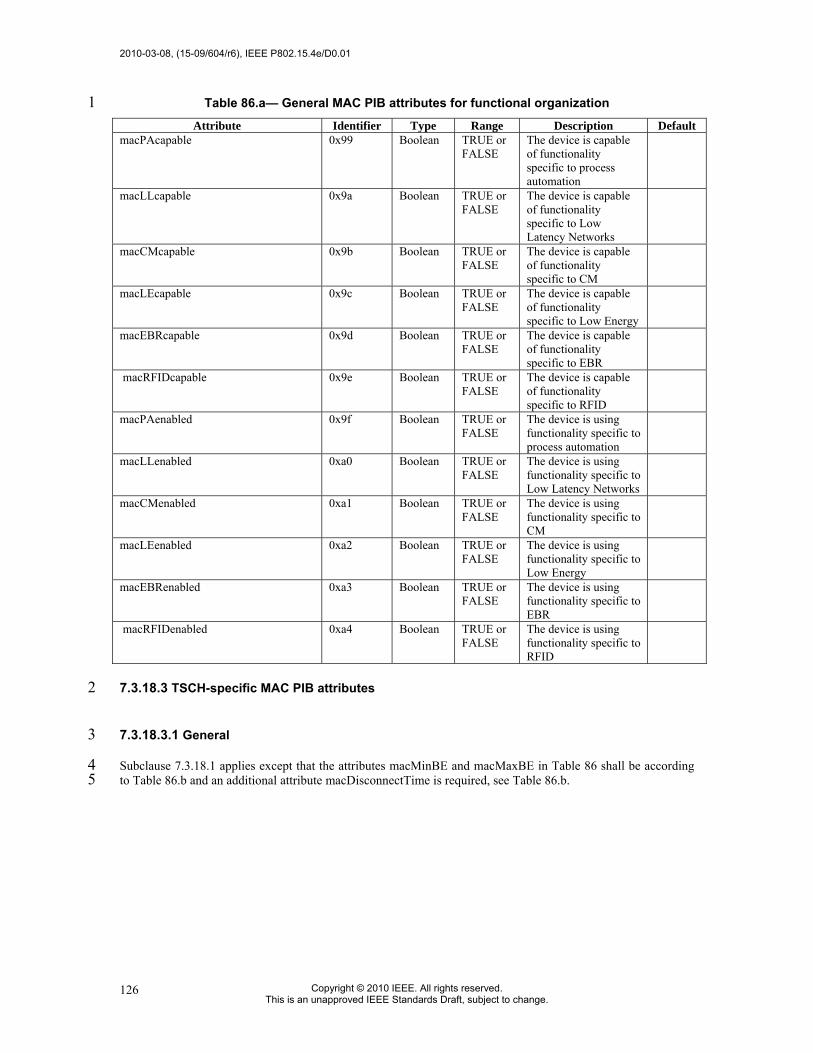
2010-03-08, (15-09/604/r6), IEEE P802.15.4e/D0.01
Copyright © 2010 IEEE. All rights reserved. This is an unapproved IEEE Standards Draft, subject to change.
126
Table 86.a— General MAC PIB attributes for functional organization 1 Attribute Identifier Type Range Description Default
macPAcapable
0x99 Boolean TRUE or FALSE
The device is capable of functionality specific to process automation
macLLcapable
0x9a Boolean TRUE or FALSE
The device is capable of functionality specific to Low Latency Networks
macCMcapable
0x9b Boolean TRUE or FALSE
The device is capable of functionality specific to CM
macLEcapable
0x9c Boolean TRUE or FALSE
The device is capable of functionality specific to Low Energy
macEBRcapable
0x9d Boolean TRUE or FALSE
The device is capable of functionality specific to EBR
macRFIDcapable 0x9e Boolean TRUE or FALSE
The device is capable of functionality specific to RFID
macPAenabled
0x9f Boolean TRUE or FALSE
The device is using functionality specific to process automation
macLLenabled
0xa0 Boolean TRUE or FALSE
The device is using functionality specific to Low Latency Networks
macCMenabled
0xa1 Boolean TRUE or FALSE
The device is using functionality specific to CM
macLEenabled
0xa2 Boolean TRUE or FALSE
The device is using functionality specific to Low Energy
macEBRenabled
0xa3 Boolean TRUE or FALSE
The device is using functionality specific to EBR
macRFIDenabled 0xa4 Boolean TRUE or FALSE
The device is using functionality specific to RFID
7.3.18.3 TSCH-specific MAC PIB attributes 2
7.3.18.3.1 General 3
Subclause 7.3.18.1 applies except that the attributes macMinBE and macMaxBE in Table 86 shall be according 4 to Table 86.b and an additional attribute macDisconnectTime is required, see Table 86.b. 5

IEEE P802.15.4e/D0.01, (15-09/604/r6), 2010-03-08
Copyright © 2009 IEEE. All rights reserved. This is an unapproved IEEE Standards Draft, subject to change.
127
Table 86.b—TSCH-specific MAC PIB attributes 1
Attribute Identifier Type Range Description DefaultmacMinBE 0x4f Integer 0–macMaxBE The minimum value of the backoff
exponent (BE) in the CSMA-CA algorithm or the TSCH-CA algorithm. See 7.5.1.4 for a detailed explanation of the backoff exponent. See 7.5.4.2 for use of the backoff exponent in TSCH-mode.
3/1
macMaxBE 0x57 Integer 3–8 The maximum value of the backoff exponent (BE) in the CSMA-CA algorithm or the TSCH- CA algorithm. See 7.5.1.4 for a detailed explanation of the backoff exponent. See 7.5.4.2 for use of the backoff exponent in TSCH-mode.
5/7
macDisconnectTime 0x8f Integer 0x00-0xFFFF Time to send out Disassociate frames before disconnecting.
2
7.3.18.3.2 TSCH-MAC PIB attributes for macSlotframeTable 3
The attributes contained in the MAC PIB for macSlotframeTable are presented in Table 86.c. 4
Table 86.c—TSCH-MAC PIB attributes for macSlotframeTable 5 Attribute Identifier Type Range Description Default
slotframeId 0x64 Integer 0x00-0xFF Identifier of the slotframe slotframeSize 0x65 Integer 0x0000-
0xFFFF Number of timeslots in the slotframe
activeFlag 0x66 Boolean 0x0-0x1 Flag indicating if the slotframe is currently activated
channelPage 0x67 Integer 0x00-0x1F Channel Page of channels used in this slotframe
channelMap 0x68 Bitmap Bitmap of active channels.
6
7.3.18.3.3 TSCH-MAC PIB attributes for macLinkTable 7
The attributes contained in the MAC PIB for macLinkTable are presented in Table 86.d. 8

2010-03-08, (15-09/604/r6), IEEE P802.15.4e/D0.01
Copyright © 2010 IEEE. All rights reserved. This is an unapproved IEEE Standards Draft, subject to change.
128
Table 86.d— TSCH-MAC PIB attributes for macLinkTable 1 Attribute Identifier Type Range Description Default
linkId 0x69 Integer 0x00-0xFF Identifier of Link linkOption 0x6a Bitmap 0x00-0x7 Flags indicating whether the link is used
for transmit, receive, or shared transmissions:
linkType 0x6b Integer 0x00-0x2 Enumeration indicating the type of link: Normal or Advertising
slotframeId 0x6c Integer 0x00-0xFF Identifier of Slotframe to which this link belongs
nodeAddress 0x6d IEEE address
16 bit address Address of the node connected to this link
timeslot 0x6e Integer 0x0000-0xFFFF
Timeslot for this link
channelOffset 0x6f 0x00-0xFF Channel offset for this link
2
7.3.18.3.4 TSCH-MAC PIB attributes for macTimeslotTemplate 3
The attributes contained in the MAC PIB for macTimeslotTemplate are presented in Table 86.e. 4
Table 86.e—TSCH-MAC PIB attributes for macTimeslotTemplate 5 Attribute Identifier Type Range Description Default
Timeslot Template Id 0x70 Integer 0x0-0xF Identifier of Timeslot Template TsCCAOffset 0x71 Integer 0x0000-
0xFFFF The time between the beginning of timeslot and start of CCA operation
TsCCA 0x72 Integer 0x0000-0xFFFF
Duration of CCA
TsTxOffset 0x73 Integer 0x0000-0xFFFF
The time between the beginning of the timeslot and the start of packet transmission
TsRxOffset 0x74 Integer 0x0000-0xFFFF
Beginning of the timeslot to when the receiver must be listening
TsRxAckDelay 0x75 Integer 0x0000-0xFFFF
End of packet to when the transmitter must listen for Acknowledgment
TsTxAckDelay 0x76 Integer 0x0000-0xFFFF
End of packet to start of Acknowledgment
TsRxWait 0x77 Integer 0x0000-0xFFFF
The time to wait for start of packet
TsAckWait 0x78 Integer 0x0000-0xFFFF
The minimum time to wait for start of an Acknowledgment
TsRxTx 0x79 Integer 0x0000-0xFFFF
Transmit to Receive turnaround (12 symbols)
TsMaxAck 0x7a Integer 0x0000-0xFFFF
Transmission time to send Acknowledgment
TsMaxTx 0x7b Integer 0x0000-0xFFFF
Transmission time to send the maximum length packet (133 bytes)
6
7.3.18.3.5 TSCH-MAC PIB attributes for macHoppingSequence 7
The attributes contained in the MAC PIB for macHoppingSequence are presented in Table 86.d. 8

IEEE P802.15.4e/D0.01, (15-09/604/r6), 2010-03-08
Copyright © 2009 IEEE. All rights reserved. This is an unapproved IEEE Standards Draft, subject to change.
129
Table 86.f— TSCH-MAC PIB attributes for macHoppingSequence 1 Attribute Identifier Type Range Description Default
ID 0x90 Integer 0x01-0x0F ID of hopping sequence. Sequence 0 reserved to indicate ordered list of channels in use.
0
Length 0x91 Integer 0x00-0xFF Length of hopping sequence — Hopping Sequence 0x92 Set of
octets 0x00-0xFF List of 'Length' number of channels to be
hopped —
2
7.3.18.4 LL-specific MAC PIB attributes 3
Subclause 7.3.18.1 applies and additional attributes are required, see Table 86.b. 4
Table 86.g—LL-specific MAC PIB attributes 5
Attribute Identifier Type Range Description Default
macFAlowLatencyPAN 0x7c Boolean TRUE or FALSE
Indicates that the PAN is using the mechanisms as described in 5.3.3, 5.5.1.2, and related clauses.
Set by configuration
macFAnumTimeSlots 0x7d Integer 0 … 254 Number of time slots within superframe excluding time slot for beacon frame
20
macFAnumSensorTS 0x7e Integer 0 … macFAnum-TimeSlots
Number of sensor time slots within superframe for unidirectional communication (uplink)
20
macFAnumRetransmitTS 0x7f Integer 0 … macFAnum-SensorTS/2
Number of sensor time slots reserved for retransmission (see 5.5.1.2 and 7.3.19.6.1)
0
macFAnumActuatorTS 0x80 Integer 0 … macFAnum-TimeSlots
Number of actuator time slots within superframe for bidirectional communication
0
macFAmgmtTS 0x81 Boolean TRUE or FALSE
Indicates existence of management time slots in Online Mode
FALSE
macFAlowLatencyNWid 0x82 Integer 0x00–0xff The 8-bit identifier of the LLNW on which the device is operating. If this value is 0xff, the device is not associated.
0xff
6
7.3.18.5 DSME-specific MAC PIB attributes 7
Subclause 7.3.18.1 applies and additional attributes are required, see Table 86.h. 8

2010-03-08, (15-09/604/r6), IEEE P802.15.4e/D0.01
Copyright © 2010 IEEE. All rights reserved. This is an unapproved IEEE Standards Draft, subject to change.
130
Table 86.h—DSME-specific MAC PIB attributes 1
Attribute Identifier Type Range Description Default
Channel Index 0x83 Integer 0-31 Specifies the Channel index of the channel‘s link status reported by the source device.
avgLQI 0x84 Integer 0x00-0xff A characterization of the link quality between a source device and a destination device on the channel defined by Channel Index, the measurement shall be performed for each received packet during a period of LinkStatusStatisticPeriod.
avgRSSI 0x85 Integer 0-255 Average RSSI.
LinkStatisticPeriod 0x86 Interger 0x0000-0xffff
The time interval between two times of link status statistics
16
macLowEnergySuperframeSupported
0x87 Boolean TRUE or FALSE
Indication of whether the low energy superframe is operational or not. If this attribute is TRUE, the coordinator shall not transmit beacon frames regardless of BO value. This attribute shall be set to FALSE if the device is aware of the existence of allocated GTS or DSME in its two-hop neighborhood.
Implementation Specific
macFAuseGACKmechanism
0x88 Integer 0x00–0x01 This flag indicates if the coordinator is currently using the group acknowledge mechaisn for GTS frame receiptions.
0x00
2
7.3.18.6 LE-specific MAC PIB attributes 3
Subclause 7.3.18.1 applies and additional attributes are required, see Table 86.i. 4

IEEE P802.15.4e/D0.01, (15-09/604/r6), 2010-03-08
Copyright © 2009 IEEE. All rights reserved. This is an unapproved IEEE Standards Draft, subject to change.
131
Table 86.i—LE-specific MAC PIB attributes 1
Attribute Identifier Type Range Description Default
macCSLPeriod 0x88 Integer 0 … 65535 CSL sampled listening period in unit of 10 symbols. 0 means always listening, i.e., CSL off.
0
macCSLMaxPeriod 0x89 Integer 0 … 65535 Maximum CSL sampled listening period in unit of 10 symbols in the entire PAN. This determines the length of the wakeup sequence when communicating to a device whose CSL listen period is unknown. NHL may set this attribute to 0 to stop sending wakeup sequences with proper coordination with neighboring devices.
macCSLPeriod
macCSLChannelMask 0x8a Integer 32-bit bitmap relative to phyCurrentPage of channels. It represents the list of channels CSL operates on. 0 means CSL operates on phyCurrentChannel of phyCurrentPage.
0
macCSLFramePendingWaitT
0x8b Integer Number of symbols to keep the receiver on after receiving a payload frame with FCF frame pending bit set to 1.
macSecAckWaitDuration 0x8c Integer The maximum number of symbols to wait for a secure acknowledgement frame to arrive following a transmitted data frame.
macRitPeriod 0x8d Integer 0x000000 -0xffffff
The interval (in unit periods) for periodical transmission of RIT data request command in RIT mode. The unit period is aBaseSuperframeDuration. 0 means RIT is off
0
macRitDataWaitPeriod 0x8e Integer 0x00 – 0xff The maximum time (in unit period) to wait for Data frame after transmission of RIT data request command frame in RIT mode. The unit period is aBaseSuperframeDuration.
0
macRitTxWaitTime 0x8f Integer macRitPeriod - 0xffffff
The maximum time (in unit periods) that a transaction is stored by a device in RIT mode. The unit period is aBaseSurperframeDuration.
0
2
7.3.18.7 MAC Performance Metrics-specific MAC PIB attributes 3
Subclause 7.3.18.1 applies and additional attributes are required for Metrics to enable higher layers to assess 4 network performance and behavior and aide in MSDU segmentation decisions, see Table 86.j. 5
MAC PIB attributes in Table 86.j are provided to enable the assessment of network performance and connection 6 quality by higher layers. 7
MAC PIB attribute macCounterOctets defines the size of the counters providing attributes 0x91 through 0x98. 8 The values of 1 though 4 correspond to counters of 8, 16, 24, or 32 bits. Attribute macCounterOctets is read-9 only and set by the implementer depending on the PHY characteristics and other considerations. 10

2010-03-08, (15-09/604/r6), IEEE P802.15.4e/D0.01
Copyright © 2010 IEEE. All rights reserved. This is an unapproved IEEE Standards Draft, subject to change.
132
The counters implementing MAC PIB attributes 0x91 through 0x98 shall wrap to 0 when incremented beyond 1 their maximum value (2^(8*macCounterOctets)-1). Attributes 0x91 through 0x98 are read/write and may be 2 reset by higher layers by writing a 0 value. 3
The attributes macRetryCount, macMultipleRetryCount, macTXFailCount, macTXSuccessCount relate to data 4 frame transmission. Each MSDU transferred into the MAC layer through the MCPS-DATA.request primitive 5 shall increment exactly one of these four attribute counters depending on the final disposition of the frame as 6 described in Table 86. 7
The attributes macFCSErrorCount, macSecurityFailure, macDuplicateFrameCount, macRXSuccessCount relate 8 to data frame reception. Each MSDU transferred out of the MAC layer through the MCPS-DATA.indication 9 primitive shall increment at least one of these four attribute counters based on the status of the frame as described 10 in Table 86. 11
To create a list of PHY-related metrics, it is recommended that higher layers store relevant parameters of MCPS-12 DATA.indication such as mpduLinkQuality and DataRate for each unique Source Address (SrcAdr). The higher 13 layers may also query PLME-ED.request to establish an idle channel noise measurement. 14

IEEE P802.15.4e/D0.01, (15-09/604/r6), 2010-03-08
Copyright © 2009 IEEE. All rights reserved. This is an unapproved IEEE Standards Draft, subject to change.
133
Table 86.j—Metrics-specific MAC PIB attributes 1
Attribute Identifier Type Range Description Default
macCounterOctetsa 0x90 Integer 1 – 4 Defines the counter size in octets for attributes 0x81 through 0x88.
—b
macRetryCount 0x91 Integer 0 – (2^(8*macCounterOctets)-1)
The number of transmitted frames that required exactly one retry before acknowledgement
0
macMultipleRetryCount 0x92 Integer 0 – (2^(8*macCounterOctets)-1)
The number of transmitted frames that required more than one retry before acknowledgement
0
macTXFailCount 0x93 Integer 0 – (2^(8*macCounterOctets)-1)
The number of transmitted frames that did not result in an acknowledgement after macMaxFrameRetries
0
macTXSuccessCount 0x94 Integer 0 – (2^(8*macCounterOctets)-1)
The number of transmitted frames that were acknowledged within macAckWaitDuration after the initial data frame transmission
0
macFCSErrorCount 0x95 Integer 0 – (2^(8*macCounterOctets)-1)
The number of received frames that discarded due to an incorrect FCS
0
macSecurityFailure 0x96 Integer 0 – (2^(8*macCounterOctets)-1)
The number of received data frames that were returned from the procedure described in 7.5.9.2.3 (Incoming frame security procedure) with any status other than “SUCCESS”
0
macDuplicateFrameCount 0x97 Integer 0 – (2^(8*macCounterOctets)-1)
The number of received data frames that contained the same sequence number as a frame previously received (accounting for wrap-around of macDSN).
0
macRXSuccessCount 0x98 Integer 0 – (2^(8*macCounterOctets)-1)
The number of received data frames that were received correctly
0
a Read-only; b Implementation-dependant.
2 MAC functional description 3
7.3.19 Channel access 4
7.3.19.1 Superframe structure 5
Insert after the first paragraph the following text. 6
For LL-applications is required an additional superframe structure with beacons using a shortened frame control, 7 see 7.3.19.6. 8

2010-03-08, (15-09/604/r6), IEEE P802.15.4e/D0.01
Copyright © 2010 IEEE. All rights reserved. This is an unapproved IEEE Standards Draft, subject to change.
134
1
7.3.19.4 CSMA-CA algorithm 2
Insert after the heading of 7.3.19.4 the following subclause. 3
7.3.19.4.1 General 4
Insert before 7.3.20 the following subclauses. 5
7.3.19.4.2 TSCH-CCA Algorithm 6
When a device is operating in the TSCH-mode (see 7.1.18.3) the CCA is used to promote coexistence with other 7 users of the radio channel. For other devices in the same network the start time of transmissions, TxTxOffset, is 8 closely aligned making intra-network collision avoidance using CCA ineffective. The TSCH- devices also do 9 channel hopping so there is no backoff period used when CCA prevents a transmission. 10
When a device has a packet to transmit. it waits for a link it can transmit it in. If CCA has been enabled, the 11 MAC requests the PHY to perform a CCA at the designated time in the timeslot, TxCCAOffset, without any 12 backoff delays. Figure 69.a extend Figure 107 for the TSCH-mode. 13

IEEE P802.15.4e/D0.01, (15-09/604/r6), 2010-03-08
Copyright © 2009 IEEE. All rights reserved. This is an unapproved IEEE Standards Draft, subject to change.
135
1 Figure 69.a—TSCH-CSMA-CA Algorithm 2
7.3.19.4.3 TSCH-CA Algorithm 3
Shared links (links with the linkOption shared bit set) are intentionally assigned to more than one device for 4 transmission. This can lead to collisions and result in a transmission failure detected by not receiving an 5 acknowledgement. To reduce the probability of repeated collisions when the packets are retransmitted a 6 retransmission backoff algorithm shall be implemented for shared links. 7
When a packet is transmitted on a shared link for which an acknowledgement is expected and none is received, 8 the transmitting device shall invoke the TSCH- CA retransmission algorithm. Subsequent retransmissions may 9 be in either shared links or dedicated links. This backoff algorithm has the following properties: 10
11 • The retransmission backoff wait applies only to the transmission on shared links. There is no waiting for 12
transmission on dedicated links. 13

2010-03-08, (15-09/604/r6), IEEE P802.15.4e/D0.01
Copyright © 2010 IEEE. All rights reserved. This is an unapproved IEEE Standards Draft, subject to change.
136
• The retransmission backoff is calculated in the number of shared link transmission links. 1 • The backoff window increases for each consecutive failed transmission in a shared link. 2 • A successful transmission in a shared link resets the backoff window to the minimum value. 3 • The backoff window does not change when a transmission is a failure in a dedicated link. 4 • The backoff window does not change when a transmission is successful in a dedicated link and there 5
transmission queue is still not empty afterwards. 6 • The backoff window is reset to the minimum value if the transmission in a dedicated link is successful and 7
the transmit queue is then empty. 8 9
In TSCH-mode, backoff is calculated in shared links, so the CSMA-CA aUnitBackoffPeriod is not used. 10
macMaxBE and macMinBE have different default values when the device is in TSCH-mode (see table 86). 11
The device shall use an exponential backoff mechanism analogous to that described in 7.3.19.4.1. A device upon 12 encountering a transmission failure in a shared link shall initialize the backoff exponent (BE) to macMinBE. The 13 MAC sublayer shall delay for a random number in the range 0 to 2BE–1 shared links (on any slotframe) before 14 attempting a retransmission on a shared link. Retransmission on a dedicated link may occur at any time. For 15 each successive failure on a shared link, the device should increase the backoff exponent until the backoff 16 exponent = macMaxBE. Successful transmission on a shared link resets the backoff exponent to macMinBE. 17
If an acknowledgment is still not received after macMaxFrameRetries retransmissions, the MAC sublayer shall 18 assume the transmission has failed and notify the next higher layer of the failure. 19
20
7.3.19.4.4 LL-Simplified CSMA-CA 21
This subclause defines a simplified CSMA-CA algorithm that is used during Management Time slots and Shared 22 Group Timeslots in low latency networks. 23
24
The simplified CSMA-CA is a slotted CSMA-CA mechanism and follows the same algorithm as described in 25 7.3.19.4.1. However, some MAC PIB attributes have different default values as shown in Table 86.k. 26
Table 86.k—Default values for MAC PIB attributes for slotted CSMA-CA in LL-Networks 27
MAC PIB attribute Default Value in Low Latency Networks
macMinBE 3
macMaxBE 3
macMaxCSMABackoffs 0
28 The backoff slots of aUnitBackoffPeriod symbols are aligned with the start of the beacon transmission in 29 management time slots and with tSlotTxOwner in shared group time slots. 30

IEEE P802.15.4e/D0.01, (15-09/604/r6), 2010-03-08
Copyright © 2009 IEEE. All rights reserved. This is an unapproved IEEE Standards Draft, subject to change.
137
7.3.19.5 TSCH-Slotframe structure 1
7.3.19.5.1 General 2
A slotframe is a collection of timeslots repeating in time. The number of timeslots in a given slotframe (slotframe 3 size) determines how often each timeslot repeats, thus setting a communication schedule for nodes that use the 4 timeslots. When a slotframe is created, it is associated with a slotframe ID for identification. Every new 5 slotframe instance in time is called a slotframe cycle. Figure 69.b shows how nodes may communicate in a 6 sample three-timeslot slotframe. Nodes A and B communicate during timeslot 0, nodes B and C communicate 7 during timeslot 1, and timeslot 2 is not being used. Every three timeslots, the schedule repeats. The total number 8 of timeslots that has elapsed since the start of the network is called the Absolute Slot Number (ASN). The pair-9 wise assignment of a directed communication between devices in a given timeslot on a given channel offset is a 10 link. Logical channel selection in a link is made by taking (Absolute Slot Number + channel offset) % Number 11 of channels. A hopping sequence is a sorted list of physical channels that correspond to the logical channels 12 selected. There must be a one-to-one mapping of logical channel to physical channel for two devices operating in 13 a TSCH-network to agree on which channel is in use, and as such hopping sequence lengths are limited in a 14 TSCH-network to the number of channels in use. Hopping sequence ID 0 is reserved to indicate that the logical 15 channel and physical channel match. If other hopping sequences are to be used, a higher layer must define them 16 and these must be configured prior to joining a TSCH-network. 17
18
Cycle N Cycle N+1 Cycle N+2
TS2TS1B->C
TS0A->B
TS0A->B
TS1B->C
TS2 TS0A->B
TS1B->C
TS2
Figure 69.b—Example of a three-timeslot slotframe 19
Several performance parameters are determined by slotframe size and how timeslots are assigned within a 20 slotframe for communication. In general, shorter slotframes result in lower latency and increased bandwidth, but 21 at the expense of increased power consumption. Long slotframes generally result in higher latency and lower 22 bandwidth, but power consumption is reduced and the number of communication resources (links) is increased. 23 This affects the scale of the network. 24
25
7.3.19.5.2 Multiple slotframes 26
A given network using timeslot-based access may contain several concurrent slotframes of different sizes. 27 Slotframe size defines the bandwidth of a timeslot. A timeslot within a slotframe of a particular size repeats twice 28 as fast as a timeslot within a slotframe that is twice as long, thus allowing for double throughput on any given 29 link. Multiple slotframes may be used to define a different communication schedule for various groups of nodes 30 or to run the entire network at different duty cycles. 31
A network device may participate in one or more slotframes simultaneously, and not all devices need to 32 participate in all slotframes. By configuring a network device to participate in multiple overlapping slotframes of 33 different sizes, it is possible to establish different communication schedules and connectivity matrices that all 34 work at the same time. 35
Slotframes can be added, removed, and modified while the network is running. Even though this is the case, all 36 slotframes logically start in the same place in time. Cycle 0, timeslot 0 of every slotframe occurs at the beginning 37 of epoch, which is determined by the network device that starts the network. Because of this, timeslots in 38 different slotframes are always aligned, even though beginnings and ends of slotframes may not be (see Figure 39

2010-03-08, (15-09/604/r6), IEEE P802.15.4e/D0.01
Copyright © 2010 IEEE. All rights reserved. This is an unapproved IEEE Standards Draft, subject to change.
138
69.c). Because all slotframes begin at the same time, it is always possible to identify time of a given slotframe 1 cycle and timeslot, and ASN is the same across slotframes. 2
Figure 69.c—Multiple slotframes in the network 3
7.3.19.6 LL-Superframe structure 4
7.3.19.6.1 General Structure of Superframe 5
The superframe is divided into a beacon slot and macFAnumTimeSlots base time slots of equal length, see Figure 6 69.d. 7
8 Figure 69.d—Superframe with dedicated time slots 9
10 The first time slot of each superframe contains a beacon frame. The beacon frame is used for synchronization 11 with the superframe structure. It is also used for re-synchronization of devices that went into power save or sleep 12 mode. 13
The remaining time slots are assigned to specific devices of the network. Each time slot may have assigned a so-14 called slot owner. The slot owner has access privileges in the time slot (dedicated time slot). There is no explicit 15 addressing necessary inside the frames if the slot owner transmits in its time slot. The determination of the sender 16 is achieved through the number of the time slot. More than one device can be assigned to a time slot (shared 17 group time slot). The devices use a contention-based access method (modified CSMA/CA as described in 18 7.5.1.4.4) and a simple addressing scheme with 8-bit addresses in shared group time slots. 19
Multiple adjacent base time slots can be concatenated to a single, larger time slot. 20
As shown in Figure 69.e, there is a specific order in the meaning or usage of the time slots. 21

IEEE P802.15.4e/D0.01, (15-09/604/r6), 2010-03-08
Copyright © 2009 IEEE. All rights reserved. This is an unapproved IEEE Standards Draft, subject to change.
139
1
Figure 69.e—Usage and order of slots in a superframe 2 3 • Beacon Time Slot: always there (see 5.2) 4 • Management Time Slots: one time slot downlink, one time slot uplink, existence is configurable in 5
macFAmgmtTS during setup (see 5.3) 6 • Time slots for sensors: macFAnumSensorTS time slots uplink (uni-directional communication), 7
macFAnumRetransmitTS time slots at the beginning can be reserved for retransmissions (see 5.4) 8 • Time slots for actuators: macFAnumActuatorTS time slots uplink / downlink (bi-directional communication) 9
(see 5.5) 10
7.3.19.6.2 Beacon Time Slot 11
The beacon time slot is reserved for the LL_NW PAN coordinator to indicate the start of a superframe with the 12 transmission of a beacon. The beacon is used to synchronize the devices and to indicate the current transmission 13 mode. The beacon contains also acknowledgements for the data transmitted in the last superframe. 14
The beacon time slot is available in every superframe. 15
7.3.19.6.3 Management Time Slots 16
The first portion of a superframe after the beacon time slot is formed by the management time slots, i.e. the 17 downlink/uplink management time slots. 18
The downlink direction is defined as sending data to the device (sensor, actuator). The uplink direction is defined 19 as sending data from the device (sensor, actuator). 20
Management time slots provide a mechanism for bidirectional transmission of management data in downlink and 21 uplink direction. Downlink and uplink time slots are provided in equal number in a superframe. There are two 22 management time slots per superframe at maximum. Management down-/uplink time slots are implemented as 23 shared group access time slots. 24
Management down-/uplink time slots are used in discovery and configuration mode and are optional in the online 25 mode. 26
7.3.19.6.4 Sensor Time Slots 27
After the management time slots, time slots for the transmission of sensor data are contained in a superframe. 28 Sensor time slots allow for unidirectional communication (uplink) only. 29
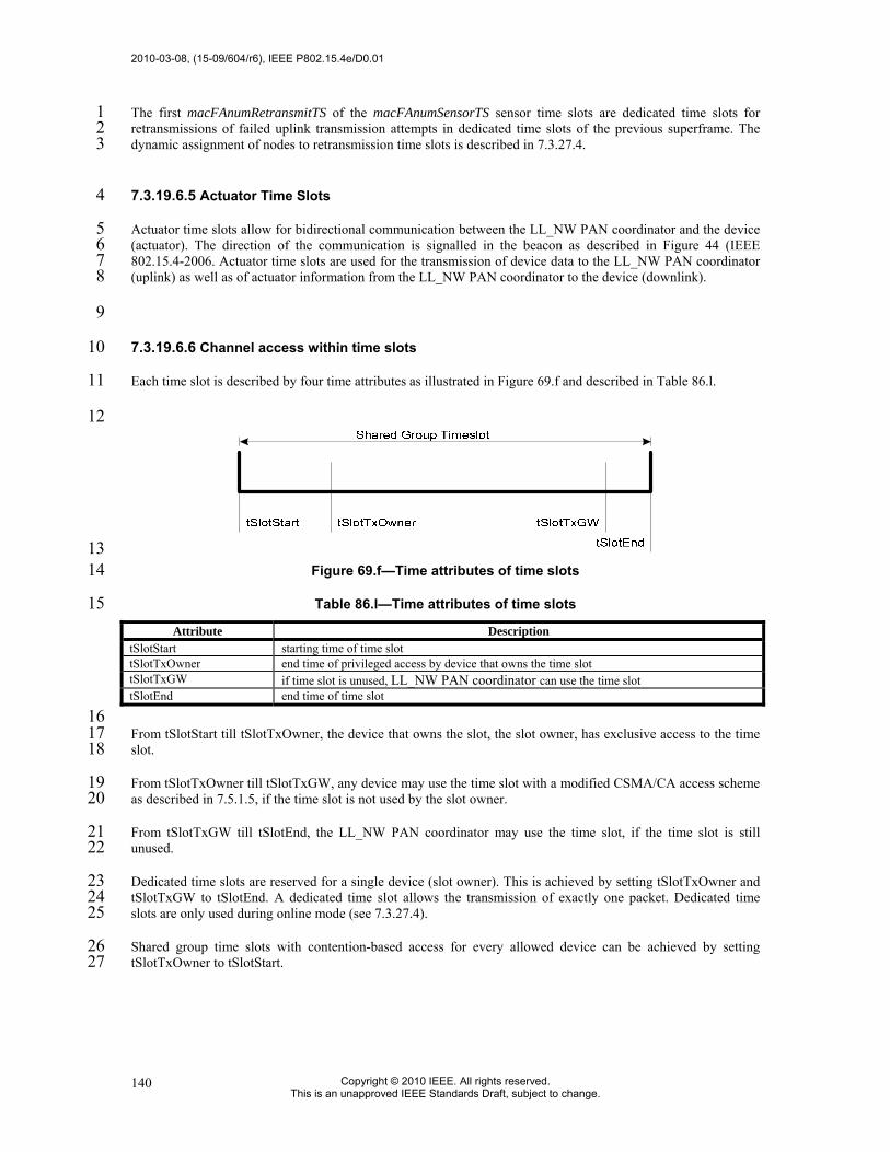
2010-03-08, (15-09/604/r6), IEEE P802.15.4e/D0.01
Copyright © 2010 IEEE. All rights reserved. This is an unapproved IEEE Standards Draft, subject to change.
140
The first macFAnumRetransmitTS of the macFAnumSensorTS sensor time slots are dedicated time slots for 1 retransmissions of failed uplink transmission attempts in dedicated time slots of the previous superframe. The 2 dynamic assignment of nodes to retransmission time slots is described in 7.3.27.4. 3
7.3.19.6.5 Actuator Time Slots 4
Actuator time slots allow for bidirectional communication between the LL_NW PAN coordinator and the device 5 (actuator). The direction of the communication is signalled in the beacon as described in Figure 44 (IEEE 6 802.15.4-2006. Actuator time slots are used for the transmission of device data to the LL_NW PAN coordinator 7 (uplink) as well as of actuator information from the LL_NW PAN coordinator to the device (downlink). 8
9
7.3.19.6.6 Channel access within time slots 10
Each time slot is described by four time attributes as illustrated in Figure 69.f and described in Table 86.l. 11
12
13 Figure 69.f—Time attributes of time slots 14
Table 86.l—Time attributes of time slots 15 Attribute Description
tSlotStart starting time of time slot tSlotTxOwner end time of privileged access by device that owns the time slot tSlotTxGW if time slot is unused, LL_NW PAN coordinator can use the time slot tSlotEnd end time of time slot
16 From tSlotStart till tSlotTxOwner, the device that owns the slot, the slot owner, has exclusive access to the time 17 slot. 18
From tSlotTxOwner till tSlotTxGW, any device may use the time slot with a modified CSMA/CA access scheme 19 as described in 7.5.1.5, if the time slot is not used by the slot owner. 20
From tSlotTxGW till tSlotEnd, the LL_NW PAN coordinator may use the time slot, if the time slot is still 21 unused. 22
Dedicated time slots are reserved for a single device (slot owner). This is achieved by setting tSlotTxOwner and 23 tSlotTxGW to tSlotEnd. A dedicated time slot allows the transmission of exactly one packet. Dedicated time 24 slots are only used during online mode (see 7.3.27.4). 25
Shared group time slots with contention-based access for every allowed device can be achieved by setting 26 tSlotTxOwner to tSlotStart. 27

IEEE P802.15.4e/D0.01, (15-09/604/r6), 2010-03-08
Copyright © 2009 IEEE. All rights reserved. This is an unapproved IEEE Standards Draft, subject to change.
141
7.3.19.7 LE-Functional description 1
7.3.19.7.1 LE-Contention access period (CAP) 2
When macCSLPeriod is set to non-zero, CSL is deployed in CAP. 3
macRitPeriod shall not be set to non-zero in a beacon-enabled PAN. 4
7.3.19.7.2 LE-Scanning through channels 5
When macCSLPeriod is set to non-zero, CSL is deployed in channel scans. When macCSLMaxPeriod is set to 6 non-zero, each coordinator broadcasts beacon frames with wakeup sequence. This allows devices to perform 7 channel scans with low duty cycles. 8
9
7.3.20 Starting and maintaining PANs 10
7.3.20.1 Scanning through channels 11
7.3.20.1.1 ED channel scan 12
7.3.20.1.2 Active channel scan 13
7.3.20.1.3 Passive channel scan 14
7.3.20.1.4 Orphan channel scan 15
Insert before 7.3.20.2 the following subclause. 16
7.3.20.1.5 LE-Scan 17
When macCSLPeriod is set to non-zero, CSL is deployed in channel scans. When macCSLMaxPeriod is 18 set to non-zero, each coordinator broadcasts beacon frames with wakeup sequence. This allows devices to 19 perform channel scans with low duty cycles. 20
7.3.20.2 PAN identifier conflict resolution 21
7.3.20.5 Device discovery 22
Insert before 7.3.21 the following subclause. 23

2010-03-08, (15-09/604/r6), IEEE P802.15.4e/D0.01
Copyright © 2010 IEEE. All rights reserved. This is an unapproved IEEE Standards Draft, subject to change.
142
7.3.20.6 TSCH-network formation 1
7.3.20.6.1 Overview 2
There are two components of network formation in the TSCH-network: 3
• advertising and 4 • joining. 5 As a part of advertising, network devices that are already part of the network may send command frames 6 announcing the presence of the network. Advertisement command frames include time synchronization 7 information and a unique PAN ID. A new device trying to join listens for the Advertisement command frames. If 8 the device is pre-provisioned with a PAN ID, then it matches the advertised PAN ID with the provisioned one at 9 the higher layer. If there is no provisioned PAN ID, the device does not look for a match. When at least one 10 acceptable Advertisement command frame is received, the new device can attempt to join the network. A new 11 device joins the network by sending a Join request command frame to an advertising node. In a centralized 12 management system this join command is routed to the PAN coordinator. In a distributed management system it 13 can be processed locally. When the device is accepted into the network, the advertiser activates the device by 14 setting up slotframes and links between the new device and other existing devices. These slotframes and links 15 can also be deleted and modified and new slotframes and links added any time after a device has joined the 16 network. The sequence of messages exchanged to synchronize a device to the networks is shown in Figure 69.g. 17 The join sequence is shown in Figure 69.h. 18
A new network starts when the PAN coordinator starts to advertise (typically at the request of Network Manager 19 residing in the PAN coordinator). Being the first node in the network, the PAN coordinator starts at least one 20 slotframe, to which other network devices may later synchronize. 21
22

IEEE P802.15.4e/D0.01, (15-09/604/r6), 2010-03-08
Copyright © 2009 IEEE. All rights reserved. This is an unapproved IEEE Standards Draft, subject to change.
143
1 2
Figure 69.g—Message sequence chart for TSCH- procedure to find an advertising device 3 4

2010-03-08, (15-09/604/r6), IEEE P802.15.4e/D0.01
Copyright © 2010 IEEE. All rights reserved. This is an unapproved IEEE Standards Draft, subject to change.
144
1 2
Figure 69.h—Message sequence chart for join and activate procedures 3
7.3.20.6.2 Advertising 4
In order for new devices to join a network they must first learn network information from some devices that are 5 already part of the network. This is done through advertising. Network devices may send Advertisement 6 command frames to invite new devices into the network. This is shown in Figure 69.g. The advertising device 7 begins advertising on receipt of a ADVERTISE.request command from its NHL. At some time the device 8 wishing to join the network begins listening (as result of receiving a LISTEN.request from its NHL). Once the 9 listening device has heard an advertisement, it will generate an ADVERTISE.indication to a higher layer. The 10 higher layer may initialize the slotframe and links contained in the advertisement and switch the device into 11 TSCH-mode with a TSCH-MODE.request or wait for additional ADVERTISE.indications before doing so. At 12 this point the device is synchronized to the network and may send in a Join request. 13
Advertisement command frames contain the following information: 14
• PAN ID. 15 • Time information so new devices can synchronize to the network. 16 • Channel page and a list of RF channels in that channel page being used. 17 • Link and slotframe information so new devices know when they can transmit to the advertising device. 18 • Link and slotframe information so new devices know when to listen for transmits from the advertising 19
network device. 20 21
7.3.20.6.3 Joining 22
After a new device hears at least one valid Advertisement command frame, it may synchronize to the network 23 and start joining. Advertisement command frames contain information about the links through which the new 24 device may communicate with the advertising neighbor, and through it forward frames to the Network Manager. 25 The joining procedure may include a security handshake to mutually authenticate the joining device and the 26 Network Manager and establish the secure session between the new device and the Network Manager in addition 27

IEEE P802.15.4e/D0.01, (15-09/604/r6), 2010-03-08
Copyright © 2009 IEEE. All rights reserved. This is an unapproved IEEE Standards Draft, subject to change.
145
to allocating the communication resource to the joining device. The content of authentication messages is beyond 1 the scope of this document. 2
3
The joining process is shown in Figure 69.h. The joining device sends in a join message which contains its 4 identity, capability and security information, and a list of potential neighbors heard during listening. The 5 advertising device that receives this join request may process it locally or send it to a Network manager. If the 6 device is to be allowed into the network, then an activate command is sent containing some slotframes and links 7 that the device may use to communicate to its neighbors, which may or may not be the neighbor to whom the 8 join request was sent. After receiving the activate command, the device may be instructed to remove slotframes 9 and links obtained from advertisements. The device may receive additional slotframes and links from a Network 10 Manager or peer as required by the application. 11
7.3.21 Association and disassociation 12
7.3.21.1 Association 13
7.3.21.2 Disassociation 14
Insert the following subclause before 7.3.22. 15
7.3.21.3 Fast association 16
Fast association (FastA) is optional. A device is instructed to fast-associate with a PAN through the 17 MLME-FAST-ASSOCIATE.request primitive. The MAC sublayer of an unassociated device shall initiate 18 the fast association procedure by sending a fast association request command to the coordinator of an 19 existing PAN. After sending the fast association request command, the device shall wait for the association 20 response command from the coordinator. The association response command shall be sent by the 21 coordinator directly. Upon receiving the association response command, if the AssociationStatus field of 22 the command indicates that the association was successful, the device shall store the address contained in 23 the 16-bit Short Address field of the command in macShortAddress. Figure 69.i shows the message 24 sequence chart for fast association procedure. 25
New Device Coordinator
Fast association request
Acknowledgement
Association response
Acknowledgement
26 Figure 69.i—Message sequence chart for fast association procedure 27

2010-03-08, (15-09/604/r6), IEEE P802.15.4e/D0.01
Copyright © 2010 IEEE. All rights reserved. This is an unapproved IEEE Standards Draft, subject to change.
146
7.3.22 Synchronization 1
Insert before 7.3.22.1 the following paragraph. 2
For TSCH, Subclause 7.3.22 specifies in addition the procedures for coordinators to generate beacon frames for 3 devices to synchronize to the TSCH-network. For PANs not supporting beacons, synchronization is performed 4 by time synchronized communication within a timeslot of the slotframe. 5
7.3.22.1 Synchronization with beacons 6
Insert before 7.3.23 the following subclauses. 7
7.3.22.4 Synchronization in TSCH-network 8
7.3.22.4.1 Timeslot communication 9
During a timeslot in a slotframe, one node typically sends a frame, and another sends back an acknowledgement 10 if it successfully receives that frame. An acknowledgement can be positive (ACK) or negative (NACK). A 11 positive acknowledge indicates that the receiver has successfully received the frame and has taken ownership of 12 it for further routing. A negative acknowledgement indicates that the receiver cannot accept the frame at this 13 time, but has heard it with no errors. Both ACKs and NACKs carry timing information used by nodes to maintain 14 network synchronization. Frames sent to a unicast node address require that a link-layer acknowledgement be 15 sent in response during the same timeslot as shown in Figure 69.j. If an acknowledgement is requested and not 16 received within the timeout period, retransmission of the frame waits until the next assigned transmit timeslot (in 17 any active slotframe) to that address occurs. 18
Figure 69.j—Timeslot diagram of acknowledged transmission 19
20 As shown in Figure 69.j, the timeslot starts at time T=0 from the transmitting device’s perspective. The 21 transmitter waits TsCCAOffset µs, and then performs CCA (if active). At TsTxOffset µs, the device begins 22 transmitting the packet. The transmitter then waits TsRxAckDelay µs, then goes into receive mode to await the 23

IEEE P802.15.4e/D0.01, (15-09/604/r6), 2010-03-08
Copyright © 2009 IEEE. All rights reserved. This is an unapproved IEEE Standards Draft, subject to change.
147
acknowledgement. If the acknowledgement doesn't arrive within TsAckWait (AWT) µs the device may idle the 1 radio and that no acknowledgement will arrive. 2
On the receiver's side, at it's estimate of T=0 it waits TsRxOffset µs and then goes into receive for TsRxWait 3 (PWT) µs. If the frame has not started by that time, it may idle the receiver. Otherwise, once the frame has been 4 received, the receiver waits TsTxAckDelay µs and then sends an acknowledgement. 5
The transmitter or receiver may resynchronize clocks as described in 7.3.22.4.2. 6
EXAMPLE: 7
Below is the calculation of a 10 ms length timeslot template (from the transmitter's perspective): 8
TsTxOffset 2 120 µs TsMaxPacket 4 256 µs TsRxAckDelay 800 µs TsAckWait 400 µs TsMaxAck 2 400 µs
Total 9 976 µs 9 This allows for a maximum 133 octet frame (total including all SHR, PHR, MHR, etc.) to be sent, and an 10 acknowledgement of up to 75 octets to be returned within 10 ms. 11
12
7.3.22.4.2 Node synchronization 13
General 14 Device-to-device synchronization is necessary to maintain connection with neighbors in a slotframe-based 15 network. There are two methods for a device to synchronize to the network. 16
Acknowledgement-based synchronization 17 Unicast communication provides a basic method of time synchronization through the exchange of data and 18 acknowledgement frames. The algorithm involves the receiver calculating the delta between the expected time of 19 frame arrival and its actual arrival, and providing that information to the sender node. 20
The algorithm can be described as follows: 21
• Transmitter node sends a frame, timing the start symbol to be sent at TsTxOffset. 22 • Receiver records the timestamp TsRxActual of receiving the start symbol of the packet. 23 • Receiver calculates TimeAdj = TsTxOffset – TsRxActual. 24 • Receiver send back TimeAdj as part of acknowledgement packet. 25 • Transmitter receives the acknowledgement. If the receiver node is a clock source node, the transmitter 26
adjusts its network clock by TimeAdj. 27 28 Frame-based synchronization 29 A node may synchronize its own network clock if it receives a frame from a clock source neighbor. The 30 mechanism is similar to that of ACK-based synchronization. The receiver calculates the delta between expected 31 time of frame arrival and its actual arrival time, and adjusts its own clock by the difference. 32
The algorithm can be described as follows: 33

2010-03-08, (15-09/604/r6), IEEE P802.15.4e/D0.01
Copyright © 2010 IEEE. All rights reserved. This is an unapproved IEEE Standards Draft, subject to change.
148
• Receiver records the timestamp TsRxActual of receiving the start symbol of the packet. 1 • Receiver calculates TimeAdj = TsTxOffset – TsRxActual. 2 • Receiver adjusts its own network time by –TimeAdj. 3 Note that this procedure should only be executed if the node from which the frame is received is a clock source 4 for the receiver. 5
Figure 69.k illustrates both time synchronization mechanisms. In both cases, the receiver calculates TimeAdj to 6 either send back to the transmitter or to use locally. 7
8
9 10
Figure 69.k—Time synchronization 11 12 Network time synchronization 13 Precise time synchronization is critical to the operation of networks based on time division multiplexing. Since 14 all communication happens in timeslots, the network devices must have the same notion of when each timeslot 15 begins and ends, with minimal variation. The acknowledgement and frame-based synchronization are used for 16 pair-wise synchronization, as outlined below. In a typical TSCH-network, time propagates outwards from the 17 PAN coordinator. It is very important to maintain unidirectional time propagation and avoid timing loops. A 18 network device must periodically synchronize its network clock to at least one other network device. It may also 19 provide its network time to one or more network devices. A network device determines whether to follow a 20 neighbor’s clock based on the presence of a ClockSource flag in the corresponding neighbor’s record (configured 21 by the Network Manager). The direction of time propagation is independent of data flow in the network. 22 Neighbors included in a device’s activate packet are marked as clock sources. A higher layer may add or change 23 clock source neighbors later. 24
A network device may have more than one neighbor as its clock source. In such cases, the device may 25 synchronize its clock to any of the neighbors that are acting as its clock source. 26
Figure 69.l shows typical time propagation in TSCH-network. The arrows indicate the direction of clock 27 distribution. In this example, the PAN coordinator acts as the clock source for the entire network. Network 28 Device (ND) 20 synchronizes to the PAN coordinator only, while ND 22 synchronizes its clock to both ND 20 29 and ND 21. If ND 20 and ND 23 were to be connected, ND 20 must provide time to ND 23. Setting it up 30 otherwise would create a timing loop. 31

IEEE P802.15.4e/D0.01, (15-09/604/r6), 2010-03-08
Copyright © 2009 IEEE. All rights reserved. This is an unapproved IEEE Standards Draft, subject to change.
149
1 Figure 69.l—Time propagation in TSCH-network 2
Keep-Alive mechanism 3 In order to ensure that it remains synchronized with the TSCH-network (and to detect when paths may be down) 4 a network device shall ensure that it communicates with each of its clock sources at least once per Keep Alive 5 period. 6
If a network device has not sent a packet to its clock parent within this interval, it shall send a Keep-Alive 7 command frame and use the ACK to perform ACK-based synchronization as usual. 8
7.3.23 Transaction handling 9
7.3.24.2 Reception and rejection 10
Change text in 7.3.24.2. 11
For valid frames that are not broadcast, if the Frame Type subfield indicates a data or MAC command frame and 12 the Acknowledgment Request subfield of the Frame Control field is set to one, the MAC sublayer shall send an 13 acknowledgment frame. Prior to the transmission of the acknowledgment frame, the sequence number included 14 in the received data or MAC command frame shall be copied into the Sequence Number field of the 15 acknowledgment frame. This step will allow the transaction originator to know that it has received the 16 appropriate acknowledgment frame. If the PAN ID Compression subfield of the Frame Control field is set to one 17 and both destination and source addressing information is included in the frame, the MAC sublayer shall assume 18 that the omitted Source PAN Identifier field is identical to the Destination PAN Identifier field. 19
The device shall process the frame using the incoming frame security procedure described in 7.5.8.2.3. If the 20 status from the incoming frame security procedure is not SUCCESS, the MLME shall issue the corresponding 21 confirm or MLME-COMM-STATUS.indication primitive with the status parameter set to the status from the 22 incoming frame security procedure, indicating the error, and with the security-related parameters set to the 23 corresponding parameters returned by the unsecuring process. 24
For the first level of filtering, the MAC sublayer shall discard all received frames that do not contain a correct 25 value in their FCS field in the MFR (see 7.2.1.9 and Error! Reference source not found.). The FCS field shall 26 be verified on reception by recalculating the purported FCS over the MHR and MAC payload of the received 27

2010-03-08, (15-09/604/r6), IEEE P802.15.4e/D0.01
Copyright © 2010 IEEE. All rights reserved. This is an unapproved IEEE Standards Draft, subject to change.
150
frame and by subsequently comparing this value with the received FCS field. The FCS field of the received 1 frame shall be considered to be correct if these values are the same and incorrect otherwise. 2
The second level of filtering shall be dependent on whether the MAC sublayer is currently operating in 3 promiscuous mode. In promiscuous mode, the MAC sublayer shall pass all frames received after the first filter 4 directly to the upper layers without applying any more filtering or processing. The MAC sublayer shall be in 5 promiscuous mode if macPromiscuousMode is set to TRUE. 6
If the MAC sublayer is not in promiscuous mode (i.e., macPromiscuousMode is set to FALSE), it shall accept 7 only frames that satisfy all of the following third-level filtering requirements: 8
— The Frame Type subfield shall not contain a reserved frame type. 9
— The Frame Version subfield shall not contain a reserved value. 10
— If a destination PAN identifier is included in the frame, it shall match macPANId or shall be the broadcast 11 PAN identifier (0xffff). 12
— If a short destination address is included in the frame, it shall match either macShortAddress, 13 macVeryShortAddress, or the broadcast address (0xffff). Otherwise, if an extended destination address is 14 included in the frame, it shall match aExtendedAddress. 15
— If the frame type indicates that the frame is a beacon frame (frame type b000), the source PAN identifier shall 16 match macPANId unless macPANId is equal to 0xffff, in which case the beacon frame shall be accepted 17 regardless of the source PAN identifier. If the frame type indicates that the frame is a beacon frame of an LLNW 18 (frame type b100, subframe type b00) and indicates online mode, the Gateway ID field shall match 19 macFAlowLatencyNWid. 20
— If only source addressing fields are included in a data or MAC command frame, the frame shall be accepted 21 only if the device is the PAN coordinator and the source PAN identifier matches macPANId. 22
If any of the third-level filtering requirements are not satisfied, the MAC sublayer shall discard the incoming 23 frame without processing it further. If all of the third-level filtering requirements are satisfied, the frame shall be 24 considered valid and processed further. For valid frames that are not broadcast, if the Frame Type subfield 25 indicates a data or MAC command frame and the Acknowledgment Request subfield of the Frame Control field 26 is set to one, the MAC sublayer shall send an acknowledgment frame. Prior to the transmission of the 27 acknowledgment frame, the sequence number included in the received data or MAC command frame shall be 28 copied into the Sequence Number field of the acknowledgment frame. This step will allow the transaction 29 originator to know that it has received the appropriate acknowledgment frame. 30
If the PAN ID Compression subfield of the Frame Control field is set to one and both destination and source 31 addressing information is included in the frame, the MAC sublayer shall assume that the omitted Source PAN 32 Identifier field is identical to the Destination PAN Identifier field. 33
The device shall process the frame using the incoming frame security procedure described in 7.5.9.2.3. 34
If the status from the incoming frame security procedure is not SUCCESS, the MLME shall issue the 35 corresponding confirm or MLME-COMM-STATUS.indication primitive with the status parameter set to the 36 status from the incoming frame security procedure, indicating the error, and with the security-related parameters 37 set to the corresponding parameters returned by the unsecuring process. 38
If the valid frame is a data frame, the MAC sublayer shall pass the frame to the next higher layer. This is 39 achieved by issuing the MCPS-DATA.indication primitive containing the frame information. The security 40 related parameters of the MCPS-DATA.indication primitive shall be set to the corresponding parameters 41 returned by the unsecuring process. 42

IEEE P802.15.4e/D0.01, (15-09/604/r6), 2010-03-08
Copyright © 2009 IEEE. All rights reserved. This is an unapproved IEEE Standards Draft, subject to change.
151
If the valid frame is a MAC command or beacon frame, it shall be processed by the MAC sublayer accordingly, 1 and a corresponding confirm or indication primitive may be sent to the next higher layer. The security-related 2 parameters of the corresponding confirm or indication primitive shall be set to the corresponding parameters 3 returned by the unsecuring process. 4
7.3.24.4.2 Acknowledgment 5
Editorial note RS: 6 The so-called ACK delay was discussed during the IEEE 802 meeting, Atlanta, Georgia, 7 November 10-15, 2009 (cf., e.g., 09/782r1). During that discussion, it was suggested to 8 essentially keep the turn-around time the same (for 2.4 GHz PHY). Details to be looked 9 up in the minutes of that meeting. 10 Insert before 7.3.24.4.3 the following paragraph. 11
When in TSCH mode, incoming frames are acknowledged using the secure acknowledge frame as 12 described in 7.2.5.2.4. Security of the acknowledge should match that of the incoming frame. 13
When operating in TSCH-mode (see 7.1.18.3), the acknowledgement frame is sent at the time specified by the 14 macTimeslotTemplate being used (see 7.3.18 and 7.3.22.4.1); that means that macSecAckWaitDuration should 15 be set to a value corresponding to TsAckWait. 16
7.3.24.4.3 Retransmissions 17
Insert after the heading of 7.3.24.4.3 the following subclause. 18
General 19 Insert before 7.3.24.5 the following subclause. 20
TSCH-Retransmissions 21 A device that sends a data or MAC command frame with its Acknowledgment Request subfield set to one shall 22 wait for TsRxAckDelay µs. If an acknowledgment frame is received within macAckWaitDuration symbols and 23 contains the same DSN as the original transmission, the transmission is considered successful, and no further 24 action regarding retransmission shall be taken by the device. If an acknowledgment is not received within the 25 appropriate timeout or an acknowledgment is received containing a DSN that was not the same as the original 26 transmission, the device shall conclude that the single transmission attempt has failed. 27
If a single transmission attempt has failed and the transmission was indirect, the coordinator shall not retransmit 28 the data or MAC command frame. Instead, the frame shall remain in the transaction queue of the coordinator and 29 can only be extracted following the reception of a new data request command. If a new data request command is 30 received, the originating device shall transmit the frame using the same DSN as was used in the original 31 transmission. 32
If a single transmission attempt has failed and the transmission was direct, the device shall repeat the process of 33 transmitting the data or MAC command frame and waiting for the acknowledgment, up to a maximum of 34 macMaxFrameRetries times. The retransmitted frame shall contain the same DSN as was used in the original 35 transmission. Each retransmission shall only be attempted if it can be completed within the same portion of the 36 superframe, i.e., the CAP or a GTS in which the original transmission was attempted. If this timing is not 37 possible, the retransmission shall be deferred until the same portion in the next superframe. In TSCH-mode (see 38 7.1.18.3), retransmissions only occur on subsequent transmit links to the same recipient on any active slotframe. 39 If an acknowledgment is still not received after macMaxFrameRetries retransmissions, the MAC sublayer shall 40 assume the transmission has failed and notify the next higher layer of the failure. 41

2010-03-08, (15-09/604/r6), IEEE P802.15.4e/D0.01
Copyright © 2010 IEEE. All rights reserved. This is an unapproved IEEE Standards Draft, subject to change.
152
7.3.24.5 Promiscuous mode 1
7.3.25 GTS allocation and management 2
7.3.25.6 GTS expiration 3
7.3.26 Frame security 4
Editorial note RS: 5 Replace this clause entirely by the corresponding clause of the draft text submitted to the 6 Editing Team by August 15, 2009. This takes into account certain errors that are to be 7 tackled with the Corrigendum to 802.15.4-2006, as also discussed during the IEEE 802 8 meeting, Atlanta, Georgia, November 10-15, 2009 (cf., e.g., 09/782r1). During that 9 discussion, it was suggested that for TG4e editing purposes, one could anticipate the 10 Corrigendum to include these updates. Details to be looked up in the minutes of that 11 meeting. 12 Insert before 7.3.25a the following subclauses. 13
In a consolidated/integrated new edition the new subclauses should be moved before 14 7.3.25a Ranging. The numbering scheme don’t allow to have a number between 7.3.25 15 and 7.3.25a, so that it is assigned here to 7.3.27 to 7.3.29. 16
7.3.27 LL-Transmission Modes in star networks using short MAC headers 17
7.3.27.1 General 18
The transitions between the different transmission modes are illustrated in Figure 73.a. 19
20
21 22
Figure 73.a—Transitions between transmission modes 23 24 The discovery mode is the first step during network setup: the new devices are discovered and configured in the 25 second step, the configuration mode. After the successful completion of the configuration mode, the network can 26 go into online mode. Productivity data, that is, data and readings from the devices such as sensors and actuators, 27

IEEE P802.15.4e/D0.01, (15-09/604/r6), 2010-03-08
Copyright © 2009 IEEE. All rights reserved. This is an unapproved IEEE Standards Draft, subject to change.
153
can only be transmitted during online modus. In order to reconfigure a network, the configuration mode can be 1 started again. 2
7.3.27.2 Discovery Mode 3
The Discovery Mode is the first step during network setup or for the addition of new devices to an existing 4 network. 5
In discovery mode, the superframe contains only the time slot for the beacon (see 7.3.19.6.2) and two 6 management time slots, one downlink and one uplink (7.3.19.6.3). 7
A new device scans the different channels until it detects a LL_NW PAN coordinator sending beacons that 8 indicate discovery mode. 9
If a new device received a beacon indicating discovery mode, it tries to get access to the transmission medium in 10 the uplink management time slot in order to send a Discover Response frame to the LL_NW PAN coordinator. 11 The Discover Response frame is described in 7.3.11.1. The Discover Response frame contains the current 12 configuration of the device. The new device shall repeat sending the Discover Response frame until it receives an 13 Acknowledgement frame for it or the Discovery Mode is stopped by the LL_NW PAN coordinator. The 14 Acknowledgement frame is described in 7.2.5.1.4. 15
Figure 73.b illustrates the discovery mode. 16
Gateway Sensor/Actuator
Mgmt Slot
Mgmt Slot
Beacon
Beacon
Start Discover Mode
Synchronize and prepare Response
Frame that contains the current device
configurationDiscover Response Frame
Time
Beacon
Mgmt Slot
Mgmt Slot
Beacon
Mgmt Slot
Mgmt Slot
Beacon
Mgmt Slot
Mgmt Slot
Beacon
...
ResynchronizesAck Frame
Received a Discover
Response Frame;
prepare Ack
Gateway Sensor/Actuator
Mgmt Slot
Mgmt Slot
Beacon
Beacon
Start Discover Mode
Synchronize and prepare Response
Frame that contains the current device
configurationDiscover Response Frame
Time
Beacon
Mgmt Slot
Mgmt Slot
Beacon
Mgmt Slot
Mgmt Slot
Beacon
Mgmt Slot
Beacon
...
ResynchronizesAck Frame
17 Figure 73.b—Flow diagram of Discovery Mode 18
19
7.3.27.3 Configuration Mode 20
The Configuration Mode is the second step during network setup. It is also used for network reconfiguration. 21
In configuration mode, the superframe contains only the time slot for the beacon (see 7.3.19.6.2) and two 22 management time slots, one downlink and one uplink (see 7.3.19.6.3). 23
If a device received a beacon indicating configuration mode, it tries to get access to the transmission medium in 24 the uplink management time slot in order to send a Configuration Response frame to the LL_NW PAN 25

2010-03-08, (15-09/604/r6), IEEE P802.15.4e/D0.01
Copyright © 2010 IEEE. All rights reserved. This is an unapproved IEEE Standards Draft, subject to change.
154
coordinator. The Configuration Response frame is described in 7.3.11.2. The Configuration Response frame 1 contains the current configuration of the device. The new device shall repeat sending the Configuration Response 2 frame until it receives a Configuration Request frame for it or the Configuration Mode is stopped by the LL_NW 3 PAN coordinator. The Configuration Request frame is described in 7.3.11.3. The Configuration Request frame 4 contains the new configuration for the receiving device. After successfully receiving the Configuration Request 5 frame, the device sends an Acknowledgement frame to the LL_NW PAN coordinator. The Acknowledgement 6 frame is described in 7.2.5.1.4. 7
Figure 73.c illustrates the configuration mode. 8
Gateway Sensor/Actuator
Mgmt Slot
Mgmt Slot
Beacon
Beacon
Time
Beacon
Mgmt Slot
Mgmt Slot
Beacon
BeaconBeacon Resynchronizes
Received a Response
Frame; create Configuration
Request Frame
Gateway Sensor/Actuator
Mgmt Slot
Mgmt Slot
Beacon
Beacon
Start Configuration
ModeSynchronize and
prepare a Response Frame that contains the current device
configurationResponse Frame
Time
Beacon
Mgmt Slot
Mgmt Slot
Beacon
BeaconBeacon
...
ResynchronizesConfiguration Request FrameMgmt Slot
Mgmt Slot
Mgmt Slot
Mgmt Slot
Mgmt Slot
Mgmt Slot
Mgmt Slot
Mgmt Slot
BeaconBeaconBeaconBeacon
Mgmt Slot
Mgmt Slot
Mgmt Slot
Mgmt Slot
Mgmt Slot
Mgmt Slot
Mgmt Slot
Mgmt Slot
BeaconBeacon
Received the Configuration Request
with the new configuration; prepare Ack
ResynchronizesResynchronizes
Ack
9 Figure 73.c—Flow diagram of configuration mode 10
7.3.27.4 Online Mode 11
User data is only sent during Online mode. The superframe starts with a beacon and is followed by several time 12 slots. The devices can sent their data during the time slots assigned to them during configuration mode. The 13 different types of time slots are described in clause 5. 14
The existence and length of management time slots in online mode is signalled in the configuration request 15 frame. 16
The successful reception of data frames by the LL_NW PAN coordinator is acknowledged in the Group 17 Acknowledgement bitmap of the beacon frame of the next superframe (see 7.2.5.1.2.3) or in a separate Data 18 Group Acknowledgement frame (see 7.2.5.1.2.4) if so configured. This is the case for both sensor time slots and 19 actuator time slots if the actuator direction is uplink. Figure 73.d illustrates an example of the online mode for 20 uplink transmissions. The network has 3 dedicated time slots, and sensor 2 is assigned to time slot 2. 21
22

IEEE P802.15.4e/D0.01, (15-09/604/r6), 2010-03-08
Copyright © 2009 IEEE. All rights reserved. This is an unapproved IEEE Standards Draft, subject to change.
155
Data Frame by Sensor 3
Gateway Sensor/Actuator
Mgmt Slot
Beacon
Time
Beacon
Mgmt Slot
Time Slot 2
Beacon
Received a Data Frame; Set ACK in
Beacon
Gateway Sensor 2
Mgmt Slot
Start Online Mode
Synchronize and prepare a Data frame
Data Frame
Time
Beacon
Time Slot 1
Beacon
Beacon
...
Beacon (with acknowledgements)
Beacon (with acknowledgements) Resynchronizes
Resynchronize and prepare a Data frame
Time Slot 1Time Slot 1
Time Slot 3
Time Slot 1
Time Slot 3
Time Slot 2
Beacon
Data Frame by Sensor 1
Data Frame by Sensor 3
Data Frame
Data Frame by Sensor 1
Received a Data Frame; Set ACK in
Beacon
1 Figure 73.d—Flow diagram of online mode for sensor devices 2
If retransmission time slots are configured (macFAnumRetransmitTS > 0), the retransmission slots are assigned 3 to the owners of the first macFAnumRetransmitTS with the corresponding bit in the group acknowledgement 4 bitmap set to 0. Each sensor node has to execute the following algorithm in order to determine its retransmission 5 time slot r. The LL_NW PAN coordinator has to execute a similar algorithm in order to determine the senders of 6 the frames in the retransmission slots. 7
Assume that the sensor node has been assigned to sensor time slot s. ack[i] means the bit bi-1 in the group 8 acknowledgment bitmap according to Figure 53.i in 7.2.5.1.2.3. 9
if (ack[s] == false) { 10 num_failed := number of (ack[i] == 0 with 11 (macFAnumRetransmitTS+1) ≤ i ≤ (s-1)) 12 if (num_failed < macFAnumRetransmitTS) { 13 retransmission_possible = true 14 r = num_failed + 1 15 } 16 else { 17 retransmission_possible = false 18 } 19 } 20 The successful reception of data frames by actuator devices (actuator direction is downlink) is acknowledged by 21 an explicit acknowledgement frame by the corresponding actuator devices in the following superframe. This 22 means that after setting the actuator direction bit in the beacon (see 7.2.5.1.2.3) to downlink and sending a data 23 frame to one or more actuator devices, the LL_NW PAN coordinator shall set the actuator direction bit to uplink 24 in the directly following superframe. Actuator devices having successfully received a data frame from the 25 LL_NW PAN coordinator during the previous superframe shall sent an acknowledgement frame to the LL_NW 26 PAN coordinator. Actuator devices that did not receive a data frame from the LL_NW PAN coordinator, may 27 send data frames to the LL_NW PAN coordinator during this superframe with actuator direction bit set to uplink. 28 Figure 73.e illustrates the online mode with actuator devices. The network has 3 dedicated actuator time slots, 29 and actuator 2 is assigned to time slot 2. 30

2010-03-08, (15-09/604/r6), IEEE P802.15.4e/D0.01
Copyright © 2010 IEEE. All rights reserved. This is an unapproved IEEE Standards Draft, subject to change.
156
1
Actuator 2Gateway
Mgmt Slot
Beacon (actuator direction = downlink)
Time
Beacon
Mgmt Slot
Time Slot 2
Beacon
Gateway
Mgmt Slot
Start Online Mode
Synchronize
Data Frame
Time
Beacon
Time Slot 1
Beacon
Beacon
...
Beacon (actuator direction = uplink)
Beacon (with acknowledgements) Resynchronizes
Resynchronize
Time Slot 1Time Slot 1
Time Slot 3
Time Slot 1
Time Slot 3
Time Slot 2
Beacon
Data Frame to Actuator 1
Data Frame by Actuator 3
ACK Frame
ACK Frame by Actuator 1
Received a Data Frame; Set ACK in
Beacon
Received Data frame and prepare ACK frame
2 Figure 73.e—Flow diagram of online mode for actuator devices 3
7.3.28 DSME-DSME-based Multi-superframe Structure 4
7.3.28.1 DSME-based Multi-superframe Structure Definition 5
A coordinator on an DSME-based PAN can optionally bound its channel time using a multi-superframe 6 structure. A multi-superframe is a cycle of repeated superframes, each of which consists of a beacon frame, a 7 CAP and a CFP. 8
The structure of this multi-superframe is described by the values of macBeaconOrder, macSuperframeOrder, 9 and macMulti-superframeOrder. 10
The MAC PIB attribute macBeaconOrder describes the interval at which the coordinator shall transmit its 11 beacon frames. The value of macBeaconOrder, BO, and the beacon interval, BI, are related as follows: for 0 ≤ 12 BO ≤ 14, BI = aBaseSuperframeDuration * 2BO symbols. If BO = 15, the coordinator shall not transmit beacon 13 frames except when requested to do so, such as on receipt of a beacon request command. The value of 14 macSuperframeOrder and macMulti-superframeOrder shall be ignored if BO = 15. 15
The MAC PIB attribute macSuperframeOrder describes the length of a superframe. The value of 16 macSuperframeOrder, SO, and the superframe duration, SD, are related as follows: for 0 ≤ SO ≤ BO ≤ 14, SD = 17 aBaseSuperframeDuration * 2SO symbols. 18
The MAC PIB attribute macMulti-superframeOrder describes the length of a multi-superframe, which is a cycle 19 of repeated superframes. The value of macMulti-superframeOrder, MO, and the multi-superframe duration, MD, 20 are related as follows: for 0 ≤ SO ≤ MO ≤ BO ≤ 14, MD = aBaseSuperframeDuration * 2MO symbols. 21
In case, both active period and inactive period in the beacon interval are filled with cyclic multi-superframes. 22
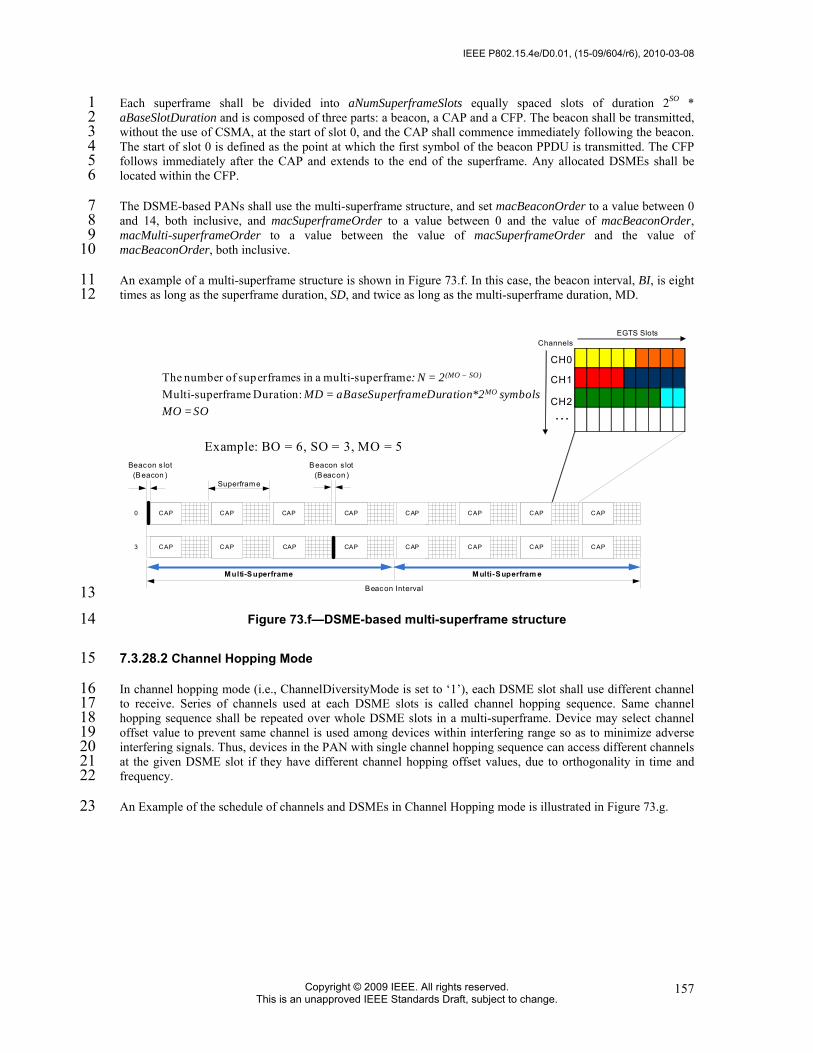
IEEE P802.15.4e/D0.01, (15-09/604/r6), 2010-03-08
Copyright © 2009 IEEE. All rights reserved. This is an unapproved IEEE Standards Draft, subject to change.
157
Each superframe shall be divided into aNumSuperframeSlots equally spaced slots of duration 2SO * 1 aBaseSlotDuration and is composed of three parts: a beacon, a CAP and a CFP. The beacon shall be transmitted, 2 without the use of CSMA, at the start of slot 0, and the CAP shall commence immediately following the beacon. 3 The start of slot 0 is defined as the point at which the first symbol of the beacon PPDU is transmitted. The CFP 4 follows immediately after the CAP and extends to the end of the superframe. Any allocated DSMEs shall be 5 located within the CFP. 6
The DSME-based PANs shall use the multi-superframe structure, and set macBeaconOrder to a value between 0 7 and 14, both inclusive, and macSuperframeOrder to a value between 0 and the value of macBeaconOrder, 8 macMulti-superframeOrder to a value between the value of macSuperframeOrder and the value of 9 macBeaconOrder, both inclusive. 10
An example of a multi-superframe structure is shown in Figure 73.f. In this case, the beacon interval, BI, is eight 11 times as long as the superframe duration, SD, and twice as long as the multi-superframe duration, MD. 12
The number of superframes in a multi-superframe: N = 2(MO – SO)
Multi-superframe Duration: MD = aBaseSuperframeDuration*2MO symbolsMO = SO
CAP0
Superframe
Beacon s lot(Beacon )
Beacon Interval
CAP
Multi-Superframe M ulti-Superfram e
Beacon s lot(Beacon )
CAP3 CAP
CAP
CAP
CAP
CAP
CAP
CAP
CAP
CAP
CAP
CAP
CAP
CAP
EGTS Slots
…
Channels
CH0
CH1
CH2
Example: BO = 6, SO = 3, MO = 5
13
Figure 73.f—DSME-based multi-superframe structure 14
7.3.28.2 Channel Hopping Mode 15
In channel hopping mode (i.e., ChannelDiversityMode is set to ‘1’), each DSME slot shall use different channel 16 to receive. Series of channels used at each DSME slots is called channel hopping sequence. Same channel 17 hopping sequence shall be repeated over whole DSME slots in a multi-superframe. Device may select channel 18 offset value to prevent same channel is used among devices within interfering range so as to minimize adverse 19 interfering signals. Thus, devices in the PAN with single channel hopping sequence can access different channels 20 at the given DSME slot if they have different channel hopping offset values, due to orthogonality in time and 21 frequency. 22
An Example of the schedule of channels and DSMEs in Channel Hopping mode is illustrated in Figure 73.g. 23

2010-03-08, (15-09/604/r6), IEEE P802.15.4e/D0.01
Copyright © 2010 IEEE. All rights reserved. This is an unapproved IEEE Standards Draft, subject to change.
158
1
Figure 73.g—Channel usage of DSME slots in DSME-based multi-superframe structure 2 In this example, channel hopping sequence is {1, 2, 3, 4, 5, 6} and the channel hopping offset values of two 3 devices are 0 and 2 respectively. For the device with channel hopping offset value of 0, DSME slots (timeslot, 4 channel) for this device are (1, 1), (2, 2), (3, 3), (4, 4), (5, 5), (6, 6), (7, 1), (8, 2), (9, 3), and so on. Similarly, for 5 the device with channel hopping offset value of 2, DSME slots are given as (1, 3), (2, 4), (3, 5), (4, 6), (5, 1), (6, 6 2), and so on. 7
Thus, channel number C at the given DSME slots index i shall be determined as: 8
C(i) = CHSeq[ (i + CHOffset) % CHSeqLength ], 9 where CHSeq[j] represents the (j)th channel number in channel hopping sequence in use, CHOffset is the channel 10 offset value and CHSeqLength is the length of channel hopping sequence. 11
Meanwhile, total number of DSME slots NoSlot in a multi-superframe is given by: 12
NoSlot = (7*2^(MO-SO)) slots 13
7.3.28.3 Group Ack 14
7.3.28.3.1 General 15
In many application systems, it may be imperative to provide the sensor nodes with a retransmission 16 opportunity, within the same superframe, for a data frame that failed in its GTS transmission. To satisfy 17 that crucial requirement, the MAC sub-layer shall provide an optional feature of group acknowledgement 18 whereby: (a) multiple GTS frames received by the coordinator in the CFP shall be acknowledged by a 19 single transmission of GACK frame by the receiver (i.e. the coordinator); and (2) new GTS timeslots shall 20 be allowed to be allocated to some of the transmitting sensor nodes for retransmission of their failed GTS 21 transmission or for transmitting additional data frames. If the group ACK mechanism is activated by a 22 coordinator, the structure of the MAC superframe shall be modified as described in the following sections. 23
7.3.28.3.2 Modified MAC Superframe Structure 24
The CFP of the MAC superframe shall be organized into several sub-periods as shown in Error! 25 Reference source not found.. Specifically, each of these sub-periods shall consist of a set of standard CFP 26 (or SCFP) slots, a group acknowledgement (GACK 1) slot, extended CFP (ECFP) slots, and another group 27 acknowledgement (GACK 2) slot. Beacon frame, transmitted by the coordinator at the beginning of the slot 28 0, shall specify the information about the CFP. That information shall be used to determine the start of the 29 SCFP and its duration. For the failed GTS transmissions in SCFP, the coordinator shall dynamically 30 allocate new time slots, in the ECFP, and inform the sensor nodes of these new allocations by transmitting 31 the GACK 1 frame at the end of the SCFP. In addition to transmitting the information about dynamic 32

IEEE P802.15.4e/D0.01, (15-09/604/r6), 2010-03-08
Copyright © 2009 IEEE. All rights reserved. This is an unapproved IEEE Standards Draft, subject to change.
159
resource assignment (i.e. allocation of time slots for use in ECFP), the GACK 1 frame shall also include a 1 group acknowledgement (in the form of a bitmap) for the GTS frame successfully received by the 2 coordinator during the SCFP. The use of group acknowledgement bitmap eliminates the need for indivisual 3 acknowledgements for the received frames and allows the coordinator to avoid from switching over from 4 Rx mode to Tx mode and then back to Rx mode while acknowledgeing individual GTS transmissions. 5 Based on the resource allocation, as specified in the GACK 1 frame, the sending nodes shall retransmit 6 their data frames in the allocated time slots in the ECFP. The coordinator shall transmit the GACK 2 frame 7 after the completion of the ECFP. The GACK 2 frame shall contain the bitmap only indicating successful 8 and failed reception of GTS frames during the ECFP. If the GACK 1 frame contains no resource 9 assignments, the ECFP and GACK 2 shall be non-existent in that superframe. 10
11
Figure 73.h—Details of DSME Superframe with ECFP and GACK 12 In addition to allow a retransmission of failed GTS transmissions in the SCFP, the ECFP shall also be used 13 for allocating additional time slots on-demand to requesting nodes. A node shall request an additional GTS 14 in the ECFP by setting a flag in the primitive while forwarding its data frame in the SCFP. The coordinator 15 shall decide, based on the availability of time slots and/or priority mechanism, if to allocate the requested 16 additional slots. The requesting node shall find the result of its request by checking the resource allocation 17 in the following GACK 1 frame. 18
7.3.28.3.3 Using Group Ack Mechanism 19
Only a LL_NW coordinator device shall control the group acknowledgement (GACK) mechanism. Sensor 20 nodes shall not initiate the request to the coordinator for the use of GACK mechanism. In a network that 21 allows the use of group ACK mechanism, nodes shall use appropriate flags and fields in the beacon frame, 22 data frame header, and GACK frame in order to facilitate the use of the GACK mechanism. The GACK 23 Flag (i.e. b32) in the beacon frame, as described in Section 7.2.6.2.2.10, transmitted by the coordinator 24 shall indicate if the GACK mechanism is activative and being used by the coordinator. GACK Flag set to 25 ‘0’ shall indicate that the coordinator is not using the mechanism. In such a case, all data transmissions by 26 the sensor nodes to the coordinator shall be acknowledged individually as is the case of the normal 27 operational mode of the original IEEE 802.15.4 specification. If the GACK Flag is set to ‘1’ in the beacon 28 frame, the transmitting coordinator shall use the GACK mechanism for its communication with sensor 29 nodes. In such a case, the coordinator shall not transmit individual ACK frames for the data frames it 30 received in GTS slots. Rather, all GTS transmissions received by the coordinator shall be acknowledged 31 together in a GACK frame transmitted by the coordinator after the last GTS time slot in the CFP. 32
While the group ACK mechanism is active, all those sensor nodes that have transmitted their data farme in 33 a GTS shall wait, after completing their GTS transmission, for the GACK frame transmitted by the 34 receiving coordinator. The bitmap in the Group Ack Flags field of the GACK frame shall be used to 35 determine if the GTS transmission by a sensor node was successful. A sensor node shall use Channel Index, 36 DSME Device List and DSME Index to determine when to start its next GTS transmission in DSME 37 portion of the superframe. That is the case when either the previous GTS transmission by the sensor node 38 failed or it requested for allocation of an extra GTS for transmitting its additional data frames. 39

2010-03-08, (15-09/604/r6), IEEE P802.15.4e/D0.01
Copyright © 2010 IEEE. All rights reserved. This is an unapproved IEEE Standards Draft, subject to change.
160
If a sensor node has additional data frames to be transmitted during the current superframe period, it shall 1 indicate its desire for additional GTS allocation by in the header of its data frame transmitted in its 2 allocated GTS in the CFP. Specifically, the node shall use ‘101’ value for Frame Type subfield (i.e. 3 b2b1b0) in the Frame Control field of the MAC frame header as specified in Table 120. The requesting 4 sensor node shall check Channel Index, DSME Device List and DSME Index to determine if its request for 5 additional GTS was granted by the coordinator. If granted, the node shall transmit its additional data frame 6 in the allocated GTS in ECFP portion of the MAC superframe. 7
The application running on an LL_NW coordinator shall enable or disable the GACK mechanism by using 8 MLME_SET.request primitive in order to set the PIB attribute macFAuseGACKmechanism, as listed in 9 Table 127.f, to appropriate value. The application shall be able to setermine if the GACK mechanism is 10 currently being used by the MAC by finding the current setting for macFAuseGACKmechanism PIB 11 attribute. The application shall use MLME_GET.request primitive for finding the current setting for 12 macFAuseGACKmechanism attribute. 13
7.3.28.4 CAP Reduction 14
If macCAPReductionFlag or the CAP Reduction Flag subfield in the DSME Superframe Specification field of a 15 beacon frame is set to TRUE, the CAP reduction shall be enabled, except the first superframe in the multi-16 superframe, other superframes do not have the CAP. Figure 73.i shows an example of the multi-superframe 17 structure when CAP reduction is enabled. 18
Number of available EGTS slots in a multi-superframe • Without CAP reduction: S1 = 16 channels * (7 *2(MO – SO)) time slots• With CAP reduction: S2 = 16 channels * (7 + (2(MO – SO)-1) * 15) time slots
Example:BO = 6, SO = 3, MO = 5
CAP0
Superframe
Beacon s lot(Beacon )
Beacon Interval
CAP
Multi-Superframe M ulti-Superfram e
Beacon s lot(Beacon )
CAP3 CAP
19
Figure 73.i— CAP Reduction in DSME-based Multi-superframe Structure 20
7.3.28.5 DSME allocation and management 21
An Enhanced Guaranteed Time Slot (DSME) functionality allows a DSME-device to operate on the channel 22 within a portion of the superframe that is dedicated (on the PAN) exclusively to that device. An DSME shall be 23 allocated by the destination device, and it shall be used only for communications between the source device and 24 the destination device. A single DSME may extend over one or more superframe slots. The destination device 25 may allocate up to seven DSMEs at the same time, provided there is sufficient capacity in the superframe. 26
An DSME shall be allocated before use, with the destination device deciding whether to allocate an DSME based 27 on the requirements of the DSME request and the current available capacity in the superframe. DSMEs shall be 28 allocated on a first-come-first-served basis, and all DSMEs shall be placed contiguously at the end of the 29 superframe and after the CAP (or after the beacon slot if CAP reduction is enabled). Each DSME shall be 30 deallocated when the DSME is no longer required, and an DSME can be deallocated at any time by the 31 destination device or the source device that originally requested the DSME. A device that has been allocated an 32 DSME may also operate in the CAP. 33
A data frame transmitted in an allocated DSME shall use only short addressing. 34

IEEE P802.15.4e/D0.01, (15-09/604/r6), 2010-03-08
Copyright © 2009 IEEE. All rights reserved. This is an unapproved IEEE Standards Draft, subject to change.
161
The management of DSMEs shall be undertaken by both of the destination device and the source device. To 1 facilitate DSME management, the destination device and the source device shall be able to store all the 2 information necessary to manage DSMEs. For each DSME, the destination device and the source device shall be 3 able to store its starting slot, length, and associated device address. 4
Each DSME requested by the source device must be the transmit DSME for the source device, and the receive 5 DSME for the destination device, so for each allocated DSME, there is no need for a device to store the direction. 6 If a destination device has been allocated an DSME, it shall enable its receiver for the entirety of the DSME. If a 7 data frame is received during an DSME and an acknowledgment is requested, the destination device shall 8 transmit the acknowledgment frame as usual. Similarly, the source device shall be able to receive an 9 acknowledgment frame during the DSME it requested. 10
A source device shall attempt to request a new DSME only if it is synchronizing with the destination device. The 11 MLME of the source device is instructed to get the timestamp and the parameters of its DSMEs from the 12 destination device by issuing the MLME-DSMEinfo.request primitive, and then the source device will send the 13 DSME information request command frame. 14
If a source device loses synchronization with the destination device, all its DSMEs allocations shall be lost. 15
The use of DSMEs is optional. 16
7.3.28.6 DSME allocation 17
A DSME-device is instructed to request the allocation of a new DSME through the MLME-GTS.request 18 primitive, with DSME characteristics set according to the requirements of the intended application and 19 DSMEFlag set to TRUE. 20
To request the allocation of a new DSME, the MLME of the Source device shall send an DSME handshake 21 command (see 7.3.10) to the Destination device. The Characteristics Type subfield of the DSME Characteristics 22 field shall be set to one (DSME allocation) and the Handshake Type subfield shall be set to zero (DSME 23 request). The DSME Length subfield of the DSMEDescriptor field shall be set according to the desired 24 characteristics of the required DSME. The DSME ABT Specification subfield shall be set according to the 25 current allocation status of all one-hop neighborhoods of the Source device. 26
After sending the DSME handshake request command frame, the source device shall wait for at most 27 anDSMERequestWaitingTime symbols, if no DSME handshake reply command frame appears within this time, 28 the MLME of the source device shall notify the next higher layer of the failure. This notification is achieved 29 when the MLME issues the MLME-GTS.confirm primitive (see 7.1.7.2) with a status of NO_DATA. 30
On receipt of an DSME handshake command frame indicating an DSME allocation request, the Destination 31 device shall first check if there is available capacity in the current multi-superframe, based on the ABT sub-block 32 maintained by the Destination device, the desired length of the request DSME and the ABT sub-block subfield in 33 the DSME handshake request command frame from the Source device. The Multi-superframe shall have 34 available capacity if enough vacant slots exist in both ABT sub-block subfields of the Destination device and the 35 Source device to satisfy the requested length. DSMEs shall be allocated on a first-come-first-served basis by the 36 Destination device provided there is sufficient bandwidth available. 37
When the Destination device determines whether capacity is available for the requested DSME, it shall generate 38 an DSME descriptor (see 7.3.10.2) with the requested specifications and the 16-bit short address of the 39 requesting source device. If the DSME was allocated successfully, the destination device shall set the DSME Slot 40 Identifier subfield in the DSME descriptor to the multi-superframe slot at which the allocated DSME begins 41 from, the DSME Length subfield in the DSME descriptor to the length of the DSME and the Device short 42 address to the address of the source device. In addition, the destination device shall notify the next higher layer of 43 the newly allocated DSME. This notification is achieved when the MLME of the destination device issues the 44 MLME-GTS.indication primitive (7.1.7.3) with the characteristics of the allocated DSME and the DSMEFlag set 45 to TRUE. If there was not sufficient capacity to allocate the requested DSME, the DSME Slot Identifier shall be 46 set to zero and the length set to the largest DSME length that can currently be supported. 47

2010-03-08, (15-09/604/r6), IEEE P802.15.4e/D0.01
Copyright © 2010 IEEE. All rights reserved. This is an unapproved IEEE Standards Draft, subject to change.
162
The Destination device shall then include the DSME descriptor in its DSME handshake command frame and 1 broadcast it to its one-hop neighbors. The Characteristics Type subfield of the DSME Characteristics field shall 2 be set to one (DSME allocation) and the Handshake Type subfield shall be set to one (DSME reply).The DSME 3 ABT Specification subfield shall be set to represent the newly allocated slots. 4
On receipt of an DSME handshake command frame indicating an DSME allocation reply, the device shall 5 process the DSME descriptor. 6
If the address in the Device Short Address subfield of the DSME descriptor does not correspond to 7 macShortAddress of the device, the device updates its ABT to reflect the neighbor’s newly allocated DSME. 8
If the newly allocated DSME is conflicting with the device’s known DSME, the device shall send an DSME 9 handshake command frame to the origin device of the DSME handshake reply command frame. The 10 Characteristics Type subfield of the DSME Characteristics field set to three (DSME duplicate allocation 11 notification) and the Handshake Type subfield set to two (DSME notify), with the DSME Slot Identifier subfield 12 in the DSME descriptor set to the multi-superframe slot at which the DSME duplicate allocated, the DSME 13 Length subfield in the DSME descriptor to the length of the duplicate allocated DSME and the Device short 14 address to the address of the device for which the DSME allocation replied. 15
If the address in the Device Short Address subfield of the DSME descriptor corresponds to macShortAddress of 16 the device, the MLME of the device shall then notify the next higher layer of whether the DSME allocation 17 request was successful. This notification is achieved when the MLME issues the MLME-GTS.confirm primitive 18 with a status of SUCCESS (if the DSME Slot Identifier in the DSME descriptor was greater than zero) or 19 DENIED (if the DSME Slot Identifier in the DSME descriptor was equal to zero or if the length did not match 20 the requested length). After that, the Source device shall broadcast an DSME handshake command frame to all 21 its one-hop neighbors. The Characteristics Type subfield of the DSME Characteristics field shall be set to one 22 (DSME allocation) and the Handshake Type subfield shall be set to two (DSME notify), with the DSME Slot 23 Identifier subfield in the DSME descriptor set to the value of the multi-superframe slot at which the new 24 allocated DSME begins, the DSME Length subfield in the DSME descriptor to the length of the allocated DSME 25 and the Device short address to the address of the destination device. 26
On receipt of an DSME handshake command frame indicating an DSME allocation notify, the device shall 27 process the DSME descriptor. The device updates its ABT to reflect the neighbor’s newly allocated DSME. If the 28 newly allocated DSME conflicts with the device’s known DSME, the device shall send an DSME handshake 29 command frame to the origin device of the DSME handshake notify command frame. The Characteristics Type 30 subfield of the DSME Characteristics field shall be set to three (DSME duplicate allocation notification) and the 31 Handshake Type subfield shall be set to two (DSME notify), with the DSME Slot Identifier subfield in the 32 DSME descriptor set to the multi-superframe slot at which the DSME duplicate allocated, the DSME Length 33 subfield in the DSME descriptor to the length of the duplicate allocated DSME and the Device short address to 34 the address of the device which sent the DSME allocation notify. 35
On receipt of an DSME handshake command frame indicating an DSME duplicate allocation notification, the 36 device shall reallocate the DSME (see 7.5.10.3). 37
An example of DSME allocation is shown in Figure 73.j. 38

IEEE P802.15.4e/D0.01, (15-09/604/r6), 2010-03-08
Copyright © 2009 IEEE. All rights reserved. This is an unapproved IEEE Standards Draft, subject to change.
163
1
Figure 73.j— Three-way Handshake for DSME Allocation 2
7.3.28.7 DSME deallocation 3
The DSME-Source device is instructed to request the deallocation of an existing DSME through the MLME-4 GTS.request primitive (see 7.1.7.1) using the characteristics of the DSME it wishes to deallocate. The 5 Destination device can request the deallocation of an existing DSME if a deallocation request from the next 6 higher layer, or the expiration of the DSME. From this point onward, the DSME to be deallocated shall not be 7 used by the device, and its stored characteristics shall be reset. 8
When an DSME deallocation is initiated by the next higher layer of the device, the MLME shall receive the 9 MLME-GTS.request primitive with the DSMEFlag set to TRUE, the Characteristics Type subfield of the 10 DSMECharacteristics parameter set to zero (DSME deallocation) and the DSME Length subfield set according 11 to the characteristics of the DSME to deallocate. 12
When an DSME deallocation is due to the DSME expiring, the MLME shall notify the next higher layer of the 13 change. This notification is achieved when the MLME issues the MLME-GTS.indication primitive with the 14 DSMEFlag set to TRUE, the DSMECharacteristics to the characteristics of the deallocated DSME and the 15 Characteristics Type subfield set to one. 16
In the case of any the deallocation of an existing DSME, the MLME shall send the DSME handshake command 17 (see 7.3.10) to the corresponding device (the Source or Destination of which the DSME to be deallocated). The 18 Characteristics Type subfield of the DSME Characteristics field shall be set to zero (DSME deallocation), and 19 the Handshake Type subfield shall be set to zero (DSME request). The DSME Length subfield of the 20 DSMEDescriptor shall be set according to the characteristics of the DSME to deallocate. The DSME ABT 21 Specification subfield shall be set according to the current allocation status of all one-hop neighborhoods of the 22 device request to deallocate the DSME. 23

2010-03-08, (15-09/604/r6), IEEE P802.15.4e/D0.01
Copyright © 2010 IEEE. All rights reserved. This is an unapproved IEEE Standards Draft, subject to change.
164
After sending the DSME handshake request command frame, the device shall wait for at most 1 anDSMERequestWaitingTime symbols, if no DSME handshake reply command frame appears within this time, 2 the MLME of the device shall notify the next higher layer of the failure. This notification is achieved when the 3 MLME issues the MLME-GTS.confirm primitive (see 7.1.7.2) with a status of NO_DATA. Then the device shall 4 determine whether stop using its DSME by the procedure described in 7.5.10.4. 5
On receipt of an DSME handshake command frame indicating an DSME deallocation request, the device shall 6 attempt to deallocate the DSME. 7
If the DSME characteristics contained in the command do not match the characteristics of a known DSME, the 8 device shall ignore the request. 9
If the DSME characteristics contained in the DSME request command match the characteristics of a known 10 DSME, the MLME of the device shall deallocate the specified DSME, update its ABT and notify the next higher 11 layer of the change. This notification is achieved when the MLME issues the MLME-GTS.indication primitive 12 (see 7.1.7.3) with the DSMEFlag set to TRUE, the DSME Characteristics parameter containing the 13 characteristics of the deallocated DSME and the Characteristics Type subfield set to one. Then, the device shall 14 broadcast an DSME handshake command to its one-hop neighbors. The Characteristics Type subfield of the 15 DSME Characteristics field of the DSME handshake command shall be set to zero (DSME deallocation), and the 16 Handshake Type subfield shall be set to one (DSME reply). The DSME Length subfield in the DSME descriptor 17 to the length of the successfully deallocated DSME and the Device Short Address to the address of the device 18 request deallocate DSME. The DSME ABT Specification subfield shall be set to represent the slots status after 19 successful deallocation. 20
On receipt of an DSME handshake command indicating an DSME deallocation reply, the device shall process 21 the DSME descriptor. 22
If the address in the Device Short Address subfield of the DSME descriptor does not correspond to 23 macShortAddress of the device, the device updates its ABT to reflect all the neighbor’s deallocated DSME. 24
If the address in the Device Short Address subfield of the DSME descriptor corresponds to macShortAddress of 25 the device, the MLME of the device shall then notify the next higher layer of whether the DSME deallocation 26 request was successful. This notification is achieved when the MLME issues the MLME-GTS.confirm primitive 27 with a status of SUCCESS (if the length in the DSME descriptor matched the requested deallocation length) or 28 DENIED (if the length in the DSME descriptor did not match the requested deallocation length). Then, the 29 device shall broadcast an DSME handshake command to all its one-hop neighbors. The Characteristics Type 30 subfield of the DSME Characteristics field shall be set to zero (DSME deallocation) and the Handshake Type 31 subfield shall be set to two (Notify), with the DSME Slot Identifier subfield and the DSME Length subfield in 32 the DSME descriptor set to the identifier and the length of the DSME deallocated respectively. 33
On receipt of an DSME handshake command indicating an DSME deallocation notify, the device shall process 34 the DSME descriptor. The device updates its ABT to reflect the neighbor’s deallocated DSME. 35
7.3.28.8 DSME reallocation 36
A DSME-device shall reallocate the DSMEs to fill the gap result from the deallocation of an DSME or regulate 37 the DSME allocation when the duplicate allocation occurs. 38
If the DSME reallocation is initiated by the next higher layer of the device, the MLME shall receive the MLME-39 GTS.request primitive with the DSMEFlag set to TRUE, the Characteristics subfield of the DSMECharacteristics 40 parameter set to two (DSME Reallocation) and the DSME Length subfield set according to the characteristics of 41 the DSME to reallocate. 42
If the DSME reallocation is due to the receipt of the DSME handshake duplicate allocation notification, the 43 MLME shall notify the next higher layer of the conflicts. This notification is achieved when the MLME issues 44 the MLME-GTS.indication primitive with the DSMEFlag set to TRUE, the DSMECharacteristics set to the 45

IEEE P802.15.4e/D0.01, (15-09/604/r6), 2010-03-08
Copyright © 2009 IEEE. All rights reserved. This is an unapproved IEEE Standards Draft, subject to change.
165
characteristics of the duplicate allocation DSME and the Characteristics Type subfield set to three (DSME 1 Duplicate allocation). 2
If the device instructed to request reallocate DSME is the source device which has requested the allocation of 3 DSME, the MLME shall generate an DSME handshake command (see 7.3.10) to the destination device which 4 has allocated the DSME, with the Characteristics Type subfield of the DSME Characteristics field shall be set to 5 two (DSME reallocation) and the Handshake Type subfield shall be set to zero (DSME request). The DSME 6 Length and the DSME Slot Identifier subfields of the DSMEDescriptor field shall be set according to the desired 7 characteristics of the reallocation DSME. The DSME ABT (Allocation Bitmap Table) Specification subfield 8 shall be set according to the current allocation status of all the one-hop neighborhoods of the device. 9
On receipt of an DSME handshake command frame indicating an DSME reallocation request, the destination 10 device shall attempt to reallocate the DSME. 11
If the DSME characteristics contained in the command do not match the characteristics of a known DSME, the 12 destination device shall ignore the request. 13
If the DSME characteristics contained in the DSME request command match the characteristics of a known 14 DSME, the destination device shall first check if there is available capacity in the current Multi-superframe, 15 based on the ABT sub-block maintained by the destination device, the length of the request reallocation DSME 16 and the ABT sub-block subfield in the DSME handshake request command frame from the Source device. The 17 Multi-superframe shall have available capacity if enough vacant slots exist in both ABT sub-block subfields of 18 the Destination device and the Source device to satisfy the requested reallocation length. DSMEs shall be 19 reallocated on a first-come-first-served basis by the Destination device provided there is sufficient bandwidth 20 available. 21
If the DSME is successfully reallocated, the destination device shall updates its ABT, and notify the next higher 22 layer of the reallocated DSME by primitive MLME-GTS.indication with the DSMEFlag set to TRUE. 23
Then the destination device shall broadcast an DSME handshake command to all its one-hop neighbors. The 24 Characteristics Type subfield of the DSME Characteristics field of the DSME handshake command shall be set 25 to two (DSME reallocation) and the Handshake Type subfield shall be set to one (DSME reply). If the DSME 26 was reallocated successfully, the DSME Slot Identifier subfield in the DSME descriptor shall be set to the multi-27 superframe slot at which the reallocated DSME begins from, the DSME Length subfield in the DSME descriptor 28 to the length of the reallocated DSME and the DSME ABT Specification subfield shall be set to represent the 29 slots status after reallocation. If there was not sufficient capacity to reallocate the requested DSME, the DSME 30 Slot Identifier shall be set to zero and the length set to the largest DSME length that can currently be supported. 31
On receipt of an DSME handshake command indicating an DSME reallocation reply, the device shall process the 32 DSME descriptor. 33
If the address in the Device Short Address subfield of the DSME descriptor does not correspond to 34 macShortAddress of the device, the device updates its ABT to reflect the neighbor’s reallocated DSME. If the 35 newly reallocated DSME is conflicting with the device’s known DSME, the device shall send an DSME 36 handshake command to the origin device of the DSME handshake reallocation reply command frame. The 37 Characteristics Type subfield of the DSME Characteristics field shall be set to three (Duplicate Allocation 38 Notification) and the Handshake Type subfield shall be set to zero (request). 39
If the address in the Device Short Address subfield of the DSME descriptor corresponds to macShortAddress of 40 the device, the MLME of the device shall then notify the next higher layer of whether the DSME reallocation 41 request was successful. This notification is achieved when the MLME issues the MLME-GTS.confirm primitive 42 with a status of SUCCESS (if the DSME Slot Identifier in the DSME descriptor was greater than zero) or 43 DENIED (if the DSME Slot Identifier in the DSME descriptor was equal to zero or if the length did not match 44 the requested length). Then, the Source device shall broadcast an DSME handshake command to all its one-hop 45 neighbors. The Characteristics Type subfield of the DSME Characteristics field shall be set to two (DSME 46 reallocation) and the Handshake Type subfield shall be set to two (DSME notify). 47

2010-03-08, (15-09/604/r6), IEEE P802.15.4e/D0.01
Copyright © 2010 IEEE. All rights reserved. This is an unapproved IEEE Standards Draft, subject to change.
166
On receipt of an DSME handshake command indicating an DSME reallocation notify, the device shall process 1 the DSME descriptor. The device updates its ABT to reflect the neighbor’s reallocated DSME. If the newly 2 reallocated DSME conflicts with the device’s known DSME, the device shall send an DSME handshake 3 command to the origin device of the DSME handshake notify command frame. The Characteristics Type subfield 4 of the DSME Characteristics field shall be set to three (DSME Duplicate Allocation Notification) and the 5 Handshake Type subfield shall be set to zero (request). 6
7.3.28.9 DSME expiration 7
The MLME of the device shall attempt to detect when a device has stopped using an DSME using the following 8 rules: 9
• The MLME of the Destination device of DSME shall assume that the source device is no longer using its 10 DSME if a data frame is not received from the source device in the DSME at least every 2*n multi-11 superframes, where n is defined below. 12
• The MLME of the Source device of DSME shall assume that the destination device is no longer using its 13 DSME if an acknowledgement frame is not received from the destination device at least every 2*n multi-14 superframes, where n is defined below. If the data frames sent in the DSME do not require acknowledgment 15 frames, the MLME of the source device will not be able to detect whether the destination device is using the 16 corresponding DSME. 17
The value of n is defined as follows: 18
n = 2(8-macBeaconOrder) 0 ≤ macBeaconOrder ≤ 8 19
n = 1 9 ≤ macBeaconOrder ≤ 14 20
7.3.28.10 DSME retrieve 21
If a loss of synchronization occurs before its allocated DSMEs of current superframe starting, the Source device 22 shall be instructed to request the timestamp and the DSME information through the MLME-DSMEinfo.request 23 primitive (see 7.1.18.1). 24
To request the timestamp and the DSME information, the MLME of the Source device shall send an DSME 25 information request command frame to the Destination device. 26
On receipt of an DSME information request command, the Destination device shall determine whether it has 27 allocated DSME slots to the requesting device. If so, the MLME of the Destination device shall send an DSME 28 information reply command frame before the end of the Source device’s DSME slot of current superframe 29 excepting the beacon slot, including the timestamp and the DSME parameters information to the Source device. 30 Otherwise, the MLME of the Destination device shall send an DSME information reply command frame 31 indicating the failure of the Source device’s DSME request at current superframe. 32
After sending the DSME information request command frame, the Source device shall wait for 33 macDSMEInfoWaitTime symbols, if the DSME information reply command frame indicating a failure or no 34 DSME information reply command frame is received, the MLME of the source device shall notify the next 35 higher layer of the failure by the MLME-DSMEinfo.confirm primitive with a status of NO_DATA. 36
On receipt of an DSME information reply command frame containing the timestamp and the DSME information, 37 the MLME of the Source device shall notify the next higher layer of the success. This notification is achieved 38 when the MLME issues the MLME-DSMEinfo.confirm primitive with a status of SUCCESS. Then the Source 39 device shall synchronize to the Destination device by using the received timestamp and continue to use its 40 allocated DSMEs during current superframe. 41
IEEE P802.15.4e/D0.01, (15-09/604/r6), 2010-03-08
Copyright © 2009 IEEE. All rights reserved. This is an unapproved IEEE Standards Draft, subject to change.
167
7.3.28.11 DSME change 1
The Destination device allocates the DSME slots to the Source device according to the first-come-first-served 2 basis. If the Destination device receives an DSME handshake allocation request command from a source device 3 with a higher priority of data transmission when there is no available DSME slots, the Destination device shall 4 reduce part or all of the DSME slots which are being used for the lower priority data transmission and allocate 5 the reduced DSME slots for the higher priority data transmission. If the Destination device receives more than 6 one DSME handshake allocation request command with the same priority of data transmission, the Destination 7 device shall allocate the DSME slots according to the first-come-first-served basis. 8
After the higher priority data transmission in the DSME slots is finished, if there are no more DSME handshake 9 allocation request commands with higher priority of data transmission are received, the Destination device shall 10 restart the DSME slots for the lower priority data transmission which were reduced previously. Otherwise, the 11 higher priority data transmission will use the DSME slots first. If the lower priority data transmission has been 12 suspended for a certain time, the Destination device shall allocate the next available DSME slots to the 13 corresponding Source device (see Table 86.h in 7.3.18.5). 14
The procedure of DSME change shall be initiated when a Destination device wants to reduce or restart the 15 allocated DSMEs through the MLME-GTS.request primitive (see 7.1.7.1). 16
When an DSME change is initiated by the next higher layer of the Destination device, the MLME shall receive 17 the MLME-GTS.request primitive with the DSMEFlag set to TRUE, the DSME Characteristics Type subfield of 18 the DSME Characteristics parameter set accordingly (i.e., 101 for DSME Reduce or 110 for DSME Restart) 19
To request the change of an existing DSME, the MLME of the Destination device shall send the DSME 20 handshake request command frame (see 7.3.10) to the Source device. The DSME Characteristics Type subfield 21 of the DSME Characteristics field shall be set accordingly (i.e., 101 for DSME Reduce or 110 for DSME 22 Restart), and other subfields set according to the characteristics of the DSME which the Destination device 23 requests the Source device to change its original DSME to. 24
The DSME handshake request command frame for DSME change contains an acknowledgment request (see 25 7.3.12), and the Source device shall confirm its receipt of DSME handshake change request command frame by 26 sending an acknowledgment frame to the destination device. 27
On receipt of the acknowledgment from the source device, the MLME of the Destination device shall notify the 28 next higher layer of the DSME change. This notification is achieved when the MLME issues the MLME-29 DSME.confirm primitive (see 7.1.20.1.3) with a status of SUCCESS, the DSMEFlag set to TRUE, the DSME 30 Characteristics Type subfield of the DSMECharacteristics parameter set to 101 for DSME Reduce or 110 for 31 DSME Restart accordingly, and other subfields set according to the characteristics of the DSME which the 32 Destination device requests the Source device to change its original DSME to. 33
On receipt of an DSME handshake request command frame for DSME change from the destination device, the 34 Source device shall immediately change its DSME according to the DSME Characteristics field in the DSME 35 handshake change request command frame. Then the MLME of the Source device shall notify the next higher 36 layer of the change. This notification is achieved when the MLME issues the MLME-GTS.indication primitive 37 (see 7.1.20.1.4) with an DSMECharacteristics parameter set according to the characteristics of the DSME which 38 the Destination device requests the Source device to change its original DSME to. 39
7.3.28.12 Robust DSME allocation 40
If the data transmitted in the DSME requires higher transmission reliability, the device is instructed to request the 41 allocation of a new Channel Hopping DSME through the MLME-GTS.request primitive with the DSMEFlag set 42 to TRUE and the DSME Characteristics type subfield set to 100 (Robust DSME Allocation). 43
To request the allocation of a new Robust DSME, the MLME shall send an DSME handshake command to the 44 Destination device with the DSME Characteristics type subfield of the DSME characteristics parameter set to 45 100 (Robust DSME Allocation) and the Handshake Type subfield shall be set to zero (DSME request). The 46

2010-03-08, (15-09/604/r6), IEEE P802.15.4e/D0.01
Copyright © 2010 IEEE. All rights reserved. This is an unapproved IEEE Standards Draft, subject to change.
168
DSME Length subfield of the DSMEDescriptor shall be set according to the desired characteristics of the 1 required DSME. The DSME ABT Specification subfield shall be set according to the current allocation status of 2 all one-hop neighborhoods of the Source device. 3
After sending the DSME handshake request command frame, the source device shall wait for at most 4 anDSMERequestWaitingTime symbols, if no DSME handshake reply command frame appears within this time, 5 the MLME of the source device shall notify the next higher layer of the failure. This notification is achieved 6 when the MLME issues the MLME-GTS.confirm primitive (see 7.1.7.2) with a status of NO_DATA. 7
On receipt of an DSME handshake command frame indicating a Robust DSME Allocation request, the 8 Destination device shall first decide whether allocating the Robust DSME or the regular DSME based on its own 9 availability. 10
If the Destination device decides to allocate the Robust DSME, it shall behave the same as 11 allocating the regular DSME except allocating DSME ABT in a Channel Hopping mode, i.e. 12 adjacent slots will be allocated different channels, and the channel selection depends on the 13 Destination device’s knowledge of current channel condition. The remaining parts of the 14 Robust DSME allocation are same with the regular DSME allocation. Within the Robust 15 DSME, the device switches to the next channel every slot according to the channel sequence 16 in the ABT. 17
18
7.3.28.13 Beacon Scheduling 19
When a new node wants to join a network, first it scans the channel. The new device uses the MLME-20 SCAN.request primitive in order to initiate a channel scan over a given list of channels. It searches for all 21 coordinators transmitting beacon frames within the maximum BI period. Then these neighboring nodes would 22 share their information of beacon bitmap with the new node. The beacon bitmap indicates the beacon frame 23 allocation information for neighboring nodes. This field is expressed by bitmap method which orderly represents 24 the schedule of beacons. Corresponding bit shall be set to 1 if a beacon is allocated in that SD. The new node will 25 search the SD which is vacant (not set to 1) in all of the received beacon bitmap of beacon frame. Once new node 26 finds vacant SD, It uses it as its own SD. 27
There can be beacon slot collision when two or more nodes are trying to compete for same SD slot number. As 28 shown in Figure 73.k, node D and node E are new nodes that join the network. These new nodes will receive the 29 beacon bitmap from their neighboring nodes. As it can be seen that node A is a common neighboring node. Thus 30 it can be the case when both new nodes E and D request same vacant SD number within same CAP. This 31 happens due to hidden node problem, because node E and D are hidden to each other, and cannot listen to each 32 others transmission. When node A receives the SD number 2 request, within same CAP, by nodes E and D then it 33 would determine which node has requested first. Node A will reply the beacon collision notification to the node 34 which has requested later. 35

IEEE P802.15.4e/D0.01, (15-09/604/r6), 2010-03-08
Copyright © 2009 IEEE. All rights reserved. This is an unapproved IEEE Standards Draft, subject to change.
169
1
Figure 73.k— New node joining the network 2
7.3.28.14 DSME Synchronization 3
The new node discovers its neighboring node through the scanning process. Then it associate with one of the 4 neighboring node in order to be part of the network. The node which the new node associates with is called its 5 parent node. 6
Now the coordinator knows that the device would track its beacon. Thus the coordinator will determine the 7 transmission time of its beacon. This beacon timestamp value is set just before transmitting the beacon frame. 8 When the device gets this beacon timestamp value then it can synchronize with its parent coordinator. 9
The effect of collision is inevitable in multiple nodes scenario, where more than one node try to use the same 10 channel at the same time. In the case of collision, the node wait for some backoff duration and then it tries to re-11 send. Thus in case of collision, beacon transmission timestamp does not become valid. In order to avoid this 12 problem, the coordinator sets macDefferedBeaconUsed value to be TRUE. When the device notice 13 macDefferedBeaconUsed value to be TRUE then it knows that coordinator uses CCA for transmitting its beacon. 14 Also the coordinator would add the number of tries it made for successful transmission. If the coordinator would 15 be able to send its beacon after 3rd try then it would set DefferedBeaconFlag value to be 3. On receipt of the 16 beacon, the device would exactly knows when the beacon is sent (by adding beacon timestamp with 17 (DefferedBeaconFlag value * 20 symbols)). Thus perfect time synchronization becomes possible. 18
7.3.28.15 Passive channel scan 19
Channel Diversity Specification in the received beacon frame shall update the value of 20 ChannelDiversitySpecification in PANDescriptor. This value is sent to the next higher layer via the MLME-21 SCAN.confirm primitive. The value of Channel Offset subfield in the received beacon shall update the value of 22 macChannelOffsetBitmap in MAC PIB attributes. For instance, if ChannelOffset is set to 0x01, the value of 23 macChannelOffsetBitmap corresponding channel shall set to ‘1’. Thus, the value of macChannelOffsetBitmap 24 shall represent if the channel offset value is used among one hop neighbor devices. 25
26
7.3.28.16 Updating superframe configuration and channel PIB attributes 27
Subclause 7.5.2.3.4 applies. For DSME-devices the following is additionally required. 28

2010-03-08, (15-09/604/r6), IEEE P802.15.4e/D0.01
Copyright © 2010 IEEE. All rights reserved. This is an unapproved IEEE Standards Draft, subject to change.
170
If a PAN uses both of the DSME and Channel Hopping mode (i.e., DSMEFlag is TRUE and 1 ChannelDiversityMode is ‘1’), the MAC sublayer shall update the values of DCHDescriptor with the values of 2 the DCHDescriptor parameter. 3
7.3.28.17 Beacon generation 4
Subclause 7.5.2.4 applies. For DSME-devices the following is additionally required. 5
If DSME and Channel Hopping mode (i.e., DSMEFlag is TRUE and ChannelDiversityMode is ‘1’) are used in 6 the PAN, the MAC sublayer shall set the Channel Diversity Specification field of the beacon frame. The value of 7 ChannelOffsetBitmap field, representing channel offset used among one hop neighbor devices, shall be set to the 8 value of macChannelOffsetBitmap in MAC PIB attributes. 9
7.3.28.18 Coexistence of beacon-enabled and non-beacon-enabled mode 10
PANs that contain both the devices of beacon-enabled mode and the devices of non-beacon-enabled mode shall 11 include the Connection Devices. 12
The device of beacon-enabled mode shall either transmit periodic beacon or track the beacon for communication 13 in the PAN. The device of non-beacon-enabled mode shall neither transmit periodic beacon nor track the beacon 14 for communication in the PAN, and it shall either request the data from other devices of non-beacon-enabled 15 mode or transmit the data upon receipt of the data request commands from the devices of non-beacon-enabled 16 mode in the PAN. Both modes shall be operated in the Connection Devices at the same time, which means the 17 Connection Device can transmit or receive frame in either beacon-enabled mode or non-beacon-enabled mode. 18
In order to maintain the beacon order consistent, the Connection Device shall store the superframe structure 19 parameters in the beacon it tracks and use those parameters in its own beacon to transmit. Moreover, the 20 Connection Device shall send the stored parameters to the neighbors actively or upon receipt of a request from 21 other devices. In order to avoid frame conflict, the Connection Device shall not communicate with the device of 22 non-beacon-enabled mode when it is tracking or transmitting beacon or communicating in beacon-enabled mode. 23
7.3.28.19 DSME-Superframe structure 24
Subclause 7.5.1.1 applies and for DSME-devices with Low Energy Superframe Support shall apply the following 25 in addition. 26
If BO = 15 and macLowEnergySuperframeSupported is FALSE, the coordinator shall not transmit beacon 27 frames except when requested to do so, such as on receipt of a beacon request command. The value of 28 macSuperframeOrder shall be ignored if BO = 15. Moreover, if macLowEnergySuperframeSupported is TRUE 29 the coordinator shall not transmit beacon frames except when requested to do so, regardless of BO value. 30
If BO = 15 and macLowEnergySuperframeSupported is FALSE, the superframe shall not exist (the value of 31 macSuperframeOrder shall be ignored). This MAC PIB attribute enables basic low energy performance that is 32 defined by the superframe structure in the beacon-enabled PAN, not driven by LE-MAC operations (see 7.3.29). 33
7.3.28.20 DSME-Contention access period (CAP) 34
Subclause 7.5.1.1.1 applies and for DSME-devices with Low Energy Superframe Support shall apply the 35 following in addition. 36
All frames, except acknowledgment and data frames that quickly follows the acknowledgment of a data request 37 command (see 7.5.6.3), transmitted in the CAP shall use a slotted CSMA-CA mechanism to access the channel. 38 A device transmitting within the CAP shall ensure that its transaction is complete (i.e., including the reception of 39

IEEE P802.15.4e/D0.01, (15-09/604/r6), 2010-03-08
Copyright © 2009 IEEE. All rights reserved. This is an unapproved IEEE Standards Draft, subject to change.
171
any acknowledgment) one IFS period (see 7.5.1.3) before the end of the CAP when 1 macLowEnergySuperframeSupported is FALSE. If this is not possible, the device shall defer its transmission 2 until the CAP of the following superframe. When macLowEnergySuperframeSupported is TRUE, on the other 3 hand, transaction shall be ensured to be completed one IFS period before the end of the inactive period. Finally, 4 if a device senses frame in CAP that does not end within CAP when macLowEnergySuperframeSupported is set 5 to TRUE, the device may continue receiving the frame until it ends before the end of the inactive period. When 6 macLowEnergySuperframeSupported is TRUE, the coordinator shall not locate DSMEs in order to avoid the 7 interference from the frames in CAP. When macLowEnergySuperframeSupported is TRUE, the coordinator shall 8 notify the devices that already associated or intend to associate the condition of 9 macLowEnergySuperframeSupported in the beacon frames. 10
7.3.28.21 DSME-Incoming and outgoing superframe timing 11
Subclause 7.5.1.2 applies and for DSME-devices shall apply the following in addition. 12
The beacon order and superframe order may be equal for all superframes on a PAN. All 13 devices may interact with the PAN only during the active portion of a superframe. 14
7.3.28.22 Multi-Channel adaptation 15
7.3.28.22.1 General 16
Single common channel approach may not be able to connect all devices in the PAN. The variance of channel 17 condition can be large and channel asymmetry between two neighboring device can happen. Multi-channel 18 adaptation is a solution to handle such case. 19
Two types of multi-channel adaptation is specified, which are synchronous multi-channel adaptation and 20 asynchronous multi-channel adaptation. The synchronous multi-channel adaptation is performed in beacon-21 enabled mode, and is handled by DSME as described in 7.5.4.4. The asynchronous multi-channel adaptation is 22 performed in non-beacon mode, and is described in this subclause. 23
7.3.28.22.2 Receiver-based communication 24
It is possible that there exists no common channel that two devices can communicate in DSME mode as there are 25 many available channels. In that case, each device selects its designated channel based on its local link quality, 26 and keep listening to its designated channel. When another device wants to communicate with it, the sender 27 device shall switch to the designated channel of the receiver device and transmit a DATA frame. Then the sender 28 device shall switch back to its own designated channel and keep listening. On receipt of the data frame from the 29 sender device, the receiver device shall switch to the designated channel of the sender device and transmit an 30 ACK frame (if requested). After sending the acknowledge frame, the receiver device shall switch back to its own 31 designated channel and keep listening at last. 32
Figure 73.l illustrated the receiver-based communications. 33
Ch-2DATA
ACKCh-1
SenderReceiver
Ch-1
Ch-2
34

2010-03-08, (15-09/604/r6), IEEE P802.15.4e/D0.01
Copyright © 2010 IEEE. All rights reserved. This is an unapproved IEEE Standards Draft, subject to change.
172
Figure 73.l— Receiver-based communication 1
7.3.28.23 Asymmetric multi-channel active scan 2
An asymmetric multi-channel active scan allows device to detect the designated channel of each coordinator or 3 detect the best channel for the device. 4
The asymmetric multi-channel active scan over a specified set of logical channels is requested using the MLME-5 SCAN.request primitive with the ScanType parameter set to 0x04. 6
For each logical channel, the device shall first switch to the channel, by setting phyCurrentChannel and 7 phyCurrentPage accordingly, and send a multi-channel beacon request command (see 7.3.11). Upon successful 8 transmission of the multi-channel beacon request command, the device shall enable its receiver for 9 [aBaseSuperframeDuration * (2n + 1)] symbols, where n is the value of the ScanDuration parameter. During this 10 time, the device shall reject all non-beacon frames and record the information contained in all unique beacons in 11 a PAN descriptor structure (see Table 55 in 7.1.5.1.1). After this time, the device shall switch to the next channel 12 and repeat the same procedure. The device shall stop repeating this procedure after visiting every channel twice. 13
If linkqualityscan flag is FALSE, the device may stop after it receives a beacon and decide the current channel as 14 its designated channel. If linkqualityscan flag is TRUE, the device make decision on its designated channel 15 comparing LQI or RSSI of the received beacons. 16
On receipt of the multi-channel beacon request command, the coordinator shall transmit a beacon (see 7.2.2.1) 17 over a set of logical channels specified in the asymmetric multi-channel beacon request command. Upon 18 successful transmission of the beacon, the coordinator shall switch to the next channel after 19 [aBaseSuperframeDuration * (2n + 1)] symbols, where n is the value of the ScanDuration parameter, and send 20 another beacon. The coordinator shall repeat the same procedure over all the logical channels specified in the 21 asymmetric multi-channel beacon request command. 22
7.3.28.24 Multi-Channel Hello 23
Multi-channel hello mechanism allows a device to announce its designated channel to its one-hop neighbor 24 devices. 25
After successfully performing the asymmetric active scan and the association, the device shall transmit the same 26 multi-channel hello command on each channel sequentially starting from its designated channel. The device can 27 request multi-channel hello reply by setting the Hello Reply Request of the multi-channel hello command to ‘1’. 28 When its neighbors receives the multi-channel hello command with Hello Reply Request set to’1’, each neighbor 29 shall transmit a multi-channel hello reply command on designated channel of the requesting device. 30
7.3.28.25 Three-way Handshake Channel Probe 31
If the channel condition is bad, the device can probe other channels and switch to a better channel. After 32 switching to the new channel, the device shall broadcast a multi-channel hello command to its one-hop neighbors 33 to notify the new channel. 34
The channel probe over a specified logical channel is requested using the MLME-SCAN.request primitive with 35 the ScanType parameter set to 0x05. 36
The device will check the condition of its designated channel by using the three-way handshake mechanism. The 37 procedure of the three-way handshake channel probing is described as follows. 38
The request device sends a channel probe request command frame to one of its neighbors on the designated 39 channel of the neighbor. On receipt of the channel probe request command, the neighbor sends a channel probe 40 reply frame back to the request device on the originator’s channel indicating in the channel probe request 41
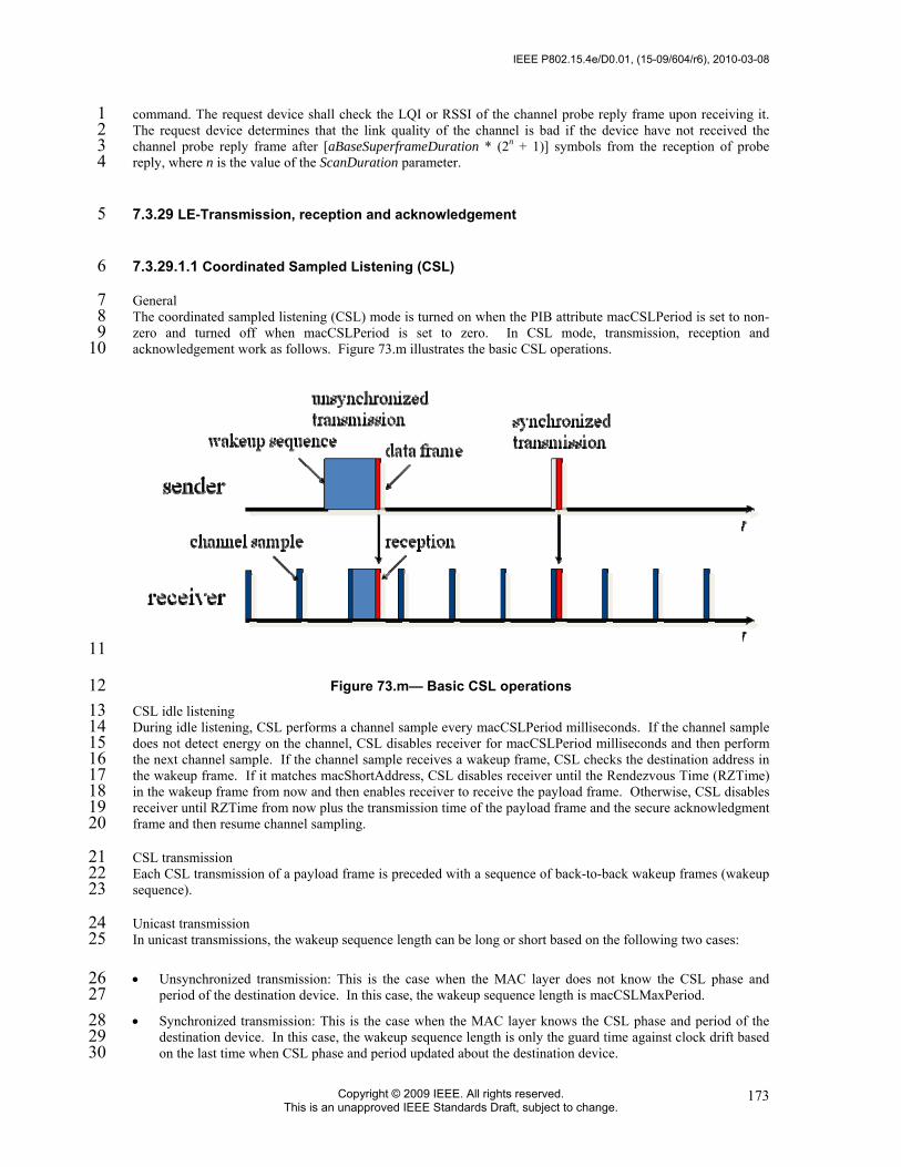
IEEE P802.15.4e/D0.01, (15-09/604/r6), 2010-03-08
Copyright © 2009 IEEE. All rights reserved. This is an unapproved IEEE Standards Draft, subject to change.
173
command. The request device shall check the LQI or RSSI of the channel probe reply frame upon receiving it. 1 The request device determines that the link quality of the channel is bad if the device have not received the 2 channel probe reply frame after [aBaseSuperframeDuration * (2n + 1)] symbols from the reception of probe 3 reply, where n is the value of the ScanDuration parameter. 4
7.3.29 LE-Transmission, reception and acknowledgement 5
7.3.29.1.1 Coordinated Sampled Listening (CSL) 6
General 7 The coordinated sampled listening (CSL) mode is turned on when the PIB attribute macCSLPeriod is set to non-8 zero and turned off when macCSLPeriod is set to zero. In CSL mode, transmission, reception and 9 acknowledgement work as follows. Figure 73.m illustrates the basic CSL operations. 10
11
Figure 73.m— Basic CSL operations 12 CSL idle listening 13 During idle listening, CSL performs a channel sample every macCSLPeriod milliseconds. If the channel sample 14 does not detect energy on the channel, CSL disables receiver for macCSLPeriod milliseconds and then perform 15 the next channel sample. If the channel sample receives a wakeup frame, CSL checks the destination address in 16 the wakeup frame. If it matches macShortAddress, CSL disables receiver until the Rendezvous Time (RZTime) 17 in the wakeup frame from now and then enables receiver to receive the payload frame. Otherwise, CSL disables 18 receiver until RZTime from now plus the transmission time of the payload frame and the secure acknowledgment 19 frame and then resume channel sampling. 20
CSL transmission 21 Each CSL transmission of a payload frame is preceded with a sequence of back-to-back wakeup frames (wakeup 22 sequence). 23
Unicast transmission 24 In unicast transmissions, the wakeup sequence length can be long or short based on the following two cases: 25
• Unsynchronized transmission: This is the case when the MAC layer does not know the CSL phase and 26 period of the destination device. In this case, the wakeup sequence length is macCSLMaxPeriod. 27
• Synchronized transmission: This is the case when the MAC layer knows the CSL phase and period of the 28 destination device. In this case, the wakeup sequence length is only the guard time against clock drift based 29 on the last time when CSL phase and period updated about the destination device. 30

2010-03-08, (15-09/604/r6), IEEE P802.15.4e/D0.01
Copyright © 2010 IEEE. All rights reserved. This is an unapproved IEEE Standards Draft, subject to change.
174
If the next higher layer has multiple frames to transmit to the same destination, it can set the FCF frame pending 1 bit to 1 in all but the last frame to maximize the throughput. 2
CSL unicast transmission is performed in the following steps by the MAC layer: 3
a) Perform CSMA-CA to acquire the channel 4 b) If the previous acknowledged payload frame to the destination has the frame pending bit set 5
and is within macCSLFramePendingWaitT, go to step 5. 6 c) If it is a synchronized transmission, wait until the destination device’s next channel sample. 7 d) For the duration of wakeup sequence length (short or long) 8 1) Construct wakeup frame with the destination short address and remaining time to payload 9
frame transmission (at the end of wakeup sequence) 10 2) Transmit wakeup frame 11 e) Transmit payload frame 12 f) Wait for up to macSecAckWaitDuration symbol time for the secure acknowledgement frame if 13
the ack request subfield in the payload frame is set to 1. 14 g) If the secure acknowledgment frame is received, update CSL phase and period information 15
about the destination device from the acknowledgment CSL sync field. 16 h) If the secure acknowledgement frame is not received, start retransmission process. 17 Multicast transmission 18 Multicast transmission is the same as unicast transmission except the following: 19
• It is always unsynchronized transmission. 20 • The destination address in wakeup frames is set to 0xffff. 21 Utilizing the optional CSL sync field 22 Selectively the next higher layer may set the CSL sync bit in FCF in a frame to propagate CSL phase and period 23 information among the neighboring devices. When the bit is set, the MAC layer automatically appends the CSL 24 sync fields to the end of MHR. 25
CSL reception 26 When a payload frame is received, the MAC layer performs the following steps: 27
a) Immediately send back a secure acknowledgment frame with the destination address set as the 28 transmitting device and its own CSL phase and period filled in the CSL sync field. The 29 acknowledgment frame can be optionally authenticated and/or encrypted depending on the current 30 security mode. 31
b) If CSL sync bit in the received payload frame is set to 1, the CSL phase and period 32 information about the transmitting device is updated with the information in the CSL sync field. 33
c) If FCF frame pending bit in the received payload frame is set to 1, keep receiver on for 34 macCSLFramePendingWaitT milliseconds before going back to CSL idle listening. Otherwise, 35 start CSL idle listening. 36
CSL over multiple channels 37 When macCSLChannelMask is set to non-zero, the CSL operations are extended to all the channels selected in 38 the bitmap. CSL idle listening performs channel sample on each channel from the lowest number to the highest 39 in a round-robin fashion. In the unsynchronized case, CSL transmission transmits a wakeup sequence of the 40 length number_of_channels*macCSLMaxPeriod before each payload frame. In the synchronized case, CSL 41 transmission calculates the next channel sample time and channel number and transmits at the next channel 42 sample time on the right channel with a short wakeup sequence. In this case, CSL phase is the duration from 43 now to the next channel sample on the first channel selected in macCSLChannelMask. 44
Turning off CSL mode to reduce latency 45 The next higher layer has the option to turn off sampled listening and stop sending wakeup sequences to reduce 46 latency for urgent messages. This assumes that the higher layer manages the coordination between the sender 47 and receiver in turning on and off sampled listening. To turn off sampled listening, the higher layer simply sets 48 macCSLPeriod to zero. To turn on sampled listening, the high layer restores macCSLPeriod to their previous 49 non-zero values. Similarly, to stop sending wakeup sequences, the higher layer sets macCSLMaxPeriod to zero 50 and restores it to its previous value to return to normal CSL mode. To request a neighboring device to turn off 51

IEEE P802.15.4e/D0.01, (15-09/604/r6), 2010-03-08
Copyright © 2009 IEEE. All rights reserved. This is an unapproved IEEE Standards Draft, subject to change.
175
sampled listening, the higher layer must send a frame to the device with frame pending bit set to 1. This prevents 1 CSL from turning off the radio before the request is processed. 2
7.3.29.2 Receiver Initiated Transmission (RIT) 3
7.3.29.2.1 General 4
The Receiver Initiated Transmission (RIT) is an alternative low energy MAC for non beacon-enabled PAN 5 (BO=15). RIT mode is turned on when PIB attribute macRitPeriod is set to non-zero value and is turned off 6 when macRitPeriod is set to zero. In RIT mode, transmission, reception and acknowledgement work as follows. 7
RIT mode is applicable to low duty cycle, low traffic load type of applications and especially suitable in the case 8 that consecutive radio emission time is limited by regional or national regulation (e.g., 950MHz band in Japan). 9 macCSLPeriod (in coordinated sample listening) and macRitPeriod cannot be set to non-zero value at the same 10 time. Figure 73.n illustrates the basic RIT operations. Figure 73.o illustrates the RIT operations when RIT data 11 request command payload carries schedule information (see 7.3.14.1.4). 12
RITdatareq.
Sender
ReceiverRx
Rx
Rx
Data
Data Pending
macRitPeriod* aBaseSuerframeDuration
macRitDataWaitPeriod
macRitTxWaitPeriod
Data exchange
・・・
・・・
t
t
RITdatareq.
13
Figure 73.n— Basic RIT operations 14
15
Figure 73.o— RIT operations when datareq carries schedule information 16 17
2010-03-08, (15-09/604/r6), IEEE P802.15.4e/D0.01
Copyright © 2010 IEEE. All rights reserved. This is an unapproved IEEE Standards Draft, subject to change.
176
7.3.29.2.2 Periodical RIT data request transmission and reception 1
In RIT mode, a device transmits RIT data request command every macRitPeriod using unslotted CSMA-CA. The 2 destination address of the command may be broadcast address (0xffff) or the address of intended transmitter of 3 data (associated coordinator). The command may optional contain a 4-octet payload defined in 7.3.14.4.3. When 4 the command carries no payload, after the transmission of RIT data request command frame, the device listens 5 for macRitDataWaitPeriod for incoming frame (except RIT data request frame) and goes back to idle state till the 6 next periodical transmission of RIT data request command. When a device is in the receiving state after 7 transmission of RIT data request command, RIT data request command frame from another device shall be 8 discarded. When data request command carries a 4-octet payload (time to 1st listen T0, number of repeat N, 9 repeat listen interval T), the device goes back to sleep for T0 period of time then listen for 10 macRitDataWaitPeriod before going back to sleep. The first listen on, it repeats a listen interval of 11 macRitDataWaitPeriod every T period of time for N times. The device shall start listening slightly before each 12 scheduled listen time based on a guard time computed from possible clock skew since the last data request 13 command transmission. 14
Upon reception of a data frame after the transmission of RIT data request command, it notifies its arrival to the 15 next higher layer by instigating MCPS-DATA.indication. Upon reception of a data frame with error (FCS or 16 security), it notifies its erroneous reception to the next higher layer by instigating MLME-FRAME-17 ERROR.indication. 18
At this point (instigation of MCPS-DATA.indication or MLME-FRAME-ERROR.indication), the device may set 19 macRitPeriod primitive to zero (RIT off) at the discretion of the next higher layer. If this is the case, it will stop 20 periodical transmission of RIT data request command and become always active until macRitPeriod primitive is 21 set to non zero value by the next higher layer again. During this period (macRitPeriod equals to zero), all 22 transactions will be handled as those of normal non beacon-enabled PAN (RxOnWhenIdle: False). 23
Figure 73.p shows the Message sequence chart for starting RIT mode. 24

IEEE P802.15.4e/D0.01, (15-09/604/r6), 2010-03-08
Copyright © 2009 IEEE. All rights reserved. This is an unapproved IEEE Standards Draft, subject to change.
177
MLME next higher layer
MLME-SET.request(macRitPeriod: non zero)
MLME-SET.confirm
Rx On formacRitDataWaitPeriod
idle state
idle state
RIT data request
RIT data request
macRitPeriod
1 2
Figure 73.p— Message sequence chart for starting RIT mode 3 4
7.3.29.2.3 Data transmission in RIT mode 5
In order to transmit data frame in RIT mode, MCPS-DATA.request primitive (with TxOption indirect) shall be 6 instigated by the next higher layer at first. When the primitive is instigated, the device shall stop its periodical 7 transmission of RIT data request, enable its receiver and wait reception of RIT data request command frame from 8 neighboring devices for at most macRitTxWaitTime. During period, all other frames except RIT data request 9 command shall be discarded. 10
Upon reception of RIT data request command frame, the MAC sublayer sends the pending data with a use of 11 unslotted CSMA-CA. In case that the Destination PAN identifier field and the Destination address field of the 12 received RIT data request command are broadcast (0xffff) and the DstPANId and DstAddr parameters of 13 instigated MCPS-DATA.request are also broadcast, the Destination PAN identifier field and the Destination 14 Address field of the outgoing data frame shall be set as the Source PAN identifier field and the Source Address 15 field of the received RIT data request command, respectively. 16
At the completion of data transmission, MCPS-DATA.confirm shall be instigated by the MAC sublayer to the 17 next higher layer. At this point, the device shall restart its transmission of periodical RIT data request 18 transmission. Also at this point, the device may set macRitPeriod primitive to zero (RIT off) at the discretion of 19 the next higher layer. If this is the case, it will continue to stop periodical transmission of RIT data request 20 command and become always active until macRitPeriod primitive is set to non zero value by the next higher 21 layer again. During this period (macRitPeriod equals to zero), all transactions will be handled as those of normal 22 non beacon-enabled PAN (RxOnWhenIdle: False). 23
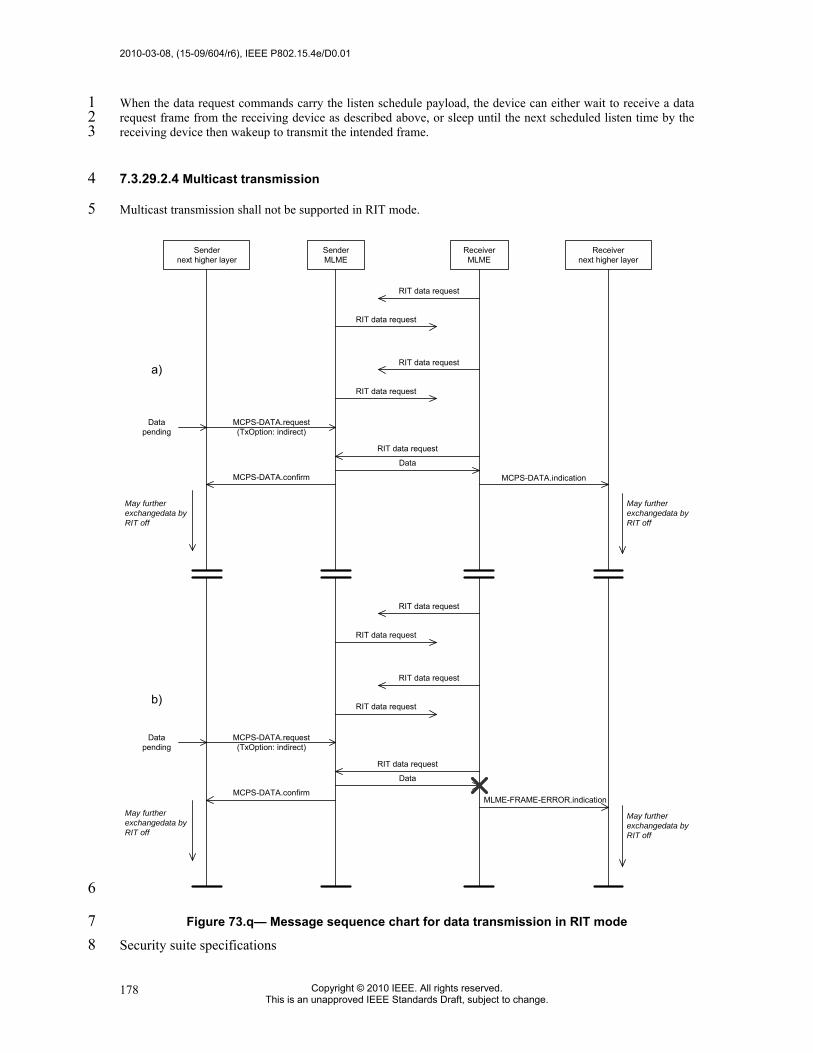
2010-03-08, (15-09/604/r6), IEEE P802.15.4e/D0.01
Copyright © 2010 IEEE. All rights reserved. This is an unapproved IEEE Standards Draft, subject to change.
178
When the data request commands carry the listen schedule payload, the device can either wait to receive a data 1 request frame from the receiving device as described above, or sleep until the next scheduled listen time by the 2 receiving device then wakeup to transmit the intended frame. 3
7.3.29.2.4 Multicast transmission 4
Multicast transmission shall not be supported in RIT mode. 5
SenderMLME
ReceiverMLME
Receivernext higher layer
Sendernext higher layer
MCPS-DATA.indication
Data
Datapending
MCPS-DATA.confirm
a)
b)
MCPS-DATA.request(TxOption: indirect)
RIT data request
RIT data request
RIT data request
RIT data request
RIT data request
MLME-FRAME-ERROR.indication
Data
Datapending
MCPS-DATA.confirm
MCPS-DATA.request(TxOption: indirect)
RIT data request
RIT data request
RIT data request
RIT data request
RIT data request
May furtherexchangedata byRIT off
May furtherexchangedata byRIT off
May furtherexchangedata byRIT off
May furtherexchangedata byRIT off
6
Figure 73.q— Message sequence chart for data transmission in RIT mode 7 Security suite specifications 8

IEEE P802.15.4e/D0.01, (15-09/604/r6), 2010-03-08
Copyright © 2009 IEEE. All rights reserved. This is an unapproved IEEE Standards Draft, subject to change.
179
Editorial note RS: 1 Replace this clause entirely by the corresponding clause of the draft text submitted to the 2 Editing Team by August 15, 2009. This takes into account certain errors that are to be 3 tackled with the Corrigendum to 802.15.4-2006, as also discussed during the IEEE 802 4 meeting, Atlanta, Georgia, November 10-15, 2009 (cf., e.g., 09/782r1). During that 5 discussion, it was suggested that for TG4e editing purposes, one could anticipate the 6 Corrigendum to include these updates. Details to be looked up in the minutes of that 7 meeting. 8
7.3.30 PIB security material 9
7.3.31 Auxiliary security header 10
7.3.32 Security operations 11
7.3.32.1 Integer and octet representation 12
7.3.32.2 CCM* Nonce 13
Insert at the end of 7.3.32.2 the following text. 14
When operating in TSCH mode (including when in Listen waiting to join a TSCH network), the nonce 15 shall be formatted as shown in Figure 77.a. 16
17 Octets: 8 5
Source address ASN
Figure 77.a—CCM* Nonce in TSCH mode 18 The source address shall be set to the extended address aExtendedAddress of the device originating the 19 frame, and ASN shall be set to the 5 LSBs of the absolute slot number, i.e. the number of timeslots elapsed 20 in the network (see 7.3.19.5.1). 21
Message sequence charts illustrating MAC-PHY interaction 22

2010-03-08, (15-09/604/r6), IEEE P802.15.4e/D0.01
Copyright © 2010 IEEE. All rights reserved. This is an unapproved IEEE Standards Draft, subject to change.
180
Annex L 1 (informative) 2
3 Bibliography 4
IEEE 802.15.1-2005, Information technology—Telecommunications and information exchange between 5 systems—Local and metropolitan area networks—Specific requirements—Part 15.1: Wireless medium access 6 control (MAC) and physical layer (PHY) specifications for wireless personal area networks (WPANs) 7
IEEE 802.15.3:2003, Information technology—Telecommunications and information exchange between 8 systems—Local and metropolitan area networks—Specific requirements—Part 15.3: Wireless Medium Access 9 Control (MAC) and Physical Layer (PHY) Specifications for High Rate Wireless Personal Area Networks 10 (WPANs) 11
IEEE 802.11- 2007, Information technology—Telecommunications and information exchange between 12 systems—Local and metropolitan area networks—Specific requirements—Part 11: Wireless LAN Medium 13 Access Control (MAC) and Physical Layer (PHY) Specifications 14
IEEE EUI-64, March 1997, Guidelines for 64-bit Global Identifier (EUI-64) Registration Authority", 15 <available at http://standards.ieee.org/regauth/oui/tutorials/EUI64.html> 16
IEC/PAS 62591:2009 Industrial communication networks - Fieldbus specifications - WirelessHARTTM 17 communication network and communication profile 18
IEC 62591:2010, Industrial communication networks – Wireless communication network and 19 communication profiles – WirelessHART™ 20
ISA 100.11a, Wireless systems for i 5 ndustrial automation: Process control and related applications 21
22
Annex L.1 will disappear in the final version. The references are given for the 23 reviewer to get more background information for the new technologies in 802.15.4e. 24
L.1 Documents for MAC enhancements in support of LL-applications 25
• 15-09/0254r0 Proposal for Factory Automation presentation of proposal for factory automation at March 09 26 IEEE 802.15.4e meeting 27
• 15-08/0827r0 Shared Group Timeslots presentation with further details on Shared Group Timeslots 28 • 15-09/0228r0 Proposal for Factory Automation text of proposal for factory automation at March 09 IEEE 29
802.15.4e meeting 30 • 15-08/0420r2 Extending the MAC Superframe of 802.15.4 Spec presentation with separate GACK 31
mechanism 32 • 15-08/0503r0 Preliminary Proposal for Factory Automation presentation of preliminary proposal for factory 33
automation at July 08 IEEE 802.15.4e meeting 34 • 15-08/0571r1 Proposal for Factory Automation presentation of proposal for factory automation at 35
September/November 08 IEEE 802.15.4e meetings 36 • 15-08/0572r0 Proposal for Factory Automation text of proposal for factory automation at September 08 37
IEEE 802.15.4e meeting 38 39

IEEE P802.15.4e/D0.01, (15-09/604/r6), 2010-03-08
Copyright © 2009 IEEE. All rights reserved. This is an unapproved IEEE Standards Draft, subject to change.
181
Insert the following Annex M before Bibliography (Annexes H, I, J, K, and L are used in existing 1 Amendments). 2

2010-03-08, (15-09/604/r6), IEEE P802.15.4e/D0.01
Copyright © 2010 IEEE. All rights reserved. This is an unapproved IEEE Standards Draft, subject to change.
182
Annex M 1 (informative) 2
3 Requirements of industrial and other application domains 4
M.1 General 5
The intentions of these add-ons are to enhance and add functionality to the IEEE 802.15.4-2006 MAC to 6
a) better support the industrial markets and 7 b) permit compatibility with modifications being proposed within the Chinese WPAN. 8 9
This functionality will facilitate industrial applications (such as addressed by IEC 62591, ISA100.11a, and 10 Wireless network for Industrial Automation-Process Automation (WIA-PA)), and those enhancements defined 11 by the Chinese WPAN standard that weren't included in the Amendment of IEEE 802.15.4c. 12
Industrial applications have requirements that are not adequately addressed by the IEEE 802.15.4-2006 standard 13 such as low latency, robustness in the harsh industrial RF environment, and determinism. 14
The Chinese Wireless Personal Area Network (CWPAN) standard has identified enhancements to improve 15 network reliability and increase network throughput to support higher duty-cycle data communication 16 applications. 17
Specifically, the MAC enhancements are grouped into two categories: 18
a) Industrial and other application domains such as Process automation, Factory automation and 19 b) Additional functional improvements such as Low energy. 20 21
To identify easier the specific amendments to which category these apply in the normative clauses, the specific 22 subclauses are named with the following acronyms in the order as they appear here. 23
a) Time Slotted Channel Hopping (TSCH), e.g. for Process automation, see M.2. 24 b) Low latency networks (LL), e.g. for Factory automation, see M.3. 25 c) Distributed Synchronous Multi-Channel Extension (DSME), e.g. for Process automation and 26
Commercial applications, see M.4. 27 d) RFID Blink frame (RFID), e.g. ???, see M.7. 28 e) Reserved for future requests. 29 30
Additional functional improvements are: 31
a) Low Energy (LE), optional, see M.5. 32 b) Enhanced Beacon request (EBR), optional, see ??? 33 c) Overhaed reduction and enhanced Security (OS), see ??? 34 d) MAC Performance Metrics (Metrics), e.g. for ??? 35 e) Fast association (FastA), e.g. for ??? 36 The convention as used in Clause 7 is that same headings needed for different solutions based on different 37 requirements have a prefix as the given acronyms above to differentiate the subclauses. 38
EXAMPLES 39
• TSCH-Heading 40 • LL-Heading 41

IEEE P802.15.4e/D0.01, (15-09/604/r6), 2010-03-08
Copyright © 2009 IEEE. All rights reserved. This is an unapproved IEEE Standards Draft, subject to change.
183
• DSME-Heading 1 2
Annex M.6 provides tutorial material for a better understanding for the different solutions specified in 3 Clauses 7. 4
M.2 Time Slotted Channel Hopping (TSCH) 5
Typical parts of the application domain of process automation are facilities for 6
⎯ Oil & gas industry, 7 • Food & beverage products, 8 • Chemical products 9 • Pharmaceutical products 10 • Water/waste water treatments 11 This application domain incurs the following major requirements: 12
• IEEE 802.15.4 header extensions for mesh support 13 • Additional addresses (source, destination) 14 • Sequence number 15 • TTL („transmissions to live“) 16
• Framework for choosing path selection mechanisms 17 • Path selection protocol 18 • Link metrics 19
M.3 Low latency networks (LL) 20
M.3.1 Typical application domains for LL-networks 21 Typical parts of the application domain of low latency networks are facilities for 22
• Factory automation (such as for automotive manufacturing) 23 • Robots 24 • Suspension tracks 25 • Portable machine tools 26 • Milling, lathes 27 • Robot revolver 28 • Filling 29 • Cargo 30 • Airport logistics 31 • Post 32 • Packaging industry 33 • Special engineering 34

2010-03-08, (15-09/604/r6), IEEE P802.15.4e/D0.01
Copyright © 2010 IEEE. All rights reserved. This is an unapproved IEEE Standards Draft, subject to change.
184
• Conveyor technique 1 • etc. 2 For this application domain exists the following major requirements: 3
• High determinism 4 • High reliability 5 • Low latency: 6
• transmission of sensor data in � 10 ms 7 • low round-trip time 8
• Many sensors per LL_NW PAN coordinator 9 • might be more than 100 sensors per LL_NW PAN coordinator 10
• Assume controlled environment (factory floor) 11 • Configuration for optimal performance 12 • Network management and frequency planning for avoidance of co-existence issues. 13 • Roaming capability (no channel hopping) 14 M.3.2 Application overview 15 Factory automation comprises today a large number of sensors and actuators observing and controlling the 16 production. As an example sensors and actuators are located on robots, suspension tracks and portable tools in 17 the automotive industry, collect data on machine tools, such as milling machines and lathes and control revolving 18 robots. Further application areas are control of conveyor belts in cargo and logistics scenarios or special 19 engineering machines. Depending on the specific needs of different factory automation branches many more 20 examples could be named. 21
Common to these sensor applications in factory automation context is the requirement of low latency and high 22 cyclic determinism. The performance should allow for reading sensor data from 20 sensors within 10ms. 23
Cabling these sensors is very time consuming and expensive. Furthermore, cables are a frequent source for 24 failures due to the harsh environment in a factory and may cause additional costs by production outage. 25
Wireless access to sensors and actuators eliminates the cabling issue and provides also advantages in case of 26 mobility and retrofit situations. 27

IEEE P802.15.4e/D0.01, (15-09/604/r6), 2010-03-08
Copyright © 2009 IEEE. All rights reserved. This is an unapproved IEEE Standards Draft, subject to change.
185
Wireless technologies that could be applied for the factory automation scenario include IEEE 802.11 (WLAN), 1 IEEE 802.15.1 (Bluetooth) and IEEE 802.15.4. IEEE 802.15.4 is designed for sensor applications and offers the 2 lowest energy consumption as well as the required communication range and capacity. Moreover, four 3 IEEE 802.15.4 channels can be utilized in good coexistence with three non-overlapping WLAN channels (see 4 Figure M.1). Bluetooth offers good real-time capabilities, but interferes inevitably with any existing WLAN 5 installations. 6
IEEE 802.15.4 is a worldwide and successfully applied standard for wireless and low power transmission of 7 sensor data. Different protocols on top of IEEE 802.15.4 (WirelessHART™ according to IEC 62591, 8 ISA100.11a or ZigBee) in the context of process automation are already in the process of standardization. Those 9 protocols aim at different requirements, but employ the same physical layer hardware as the proposed solution 10 for factory automation, which indicates potential hardware synergies and cost savings. Thus, a solution for 11 factory automation based on IEEE 802.15.4 would be beneficial. 12
IEEE 802.15.4 operates usually in Carrier Sense Multiple Access (CSMA) mode which gives no guarantees for 13 media access. Optionally, IEEE 802.15.4 specifies the beacon-enabled mode which defines a TDMA like 14 superframe structure with Guaranteed Time Slots (GTS) for deterministic access. The performance of 7 GTS in 15 an interval of 15ms does not fulfill the factory automation requirements and makes not full use of the available 16 capacity. Therefore a modification of the IEEE 802.15.4 MAC for application in industrial factory automation, 17 i.e. defining a fine granular deterministic TDMA access, is envisaged. 18
19 Figure M.1―RF technology coexistence in the 2,4GHz ISM band 20
M.3.3 Requirements and Assumptions 21 The above mentioned factory automation applications impose the following requirements to a wireless system: 22

2010-03-08, (15-09/604/r6), IEEE P802.15.4e/D0.01
Copyright © 2010 IEEE. All rights reserved. This is an unapproved IEEE Standards Draft, subject to change.
186
• high determinism, 1 • high reliability, 2 • low latency, i.e. transmission of sensor date in ≤ 10ms, 3 • low round trip time, 4 • support for many sensors per LL_NW PAN coordinator. 5 The proposed TDMA scheme, as described in the remainder of this document, supports these requirements. 6 Allocating a dedicated time slot for each sensor provides a deterministic system. The IEEE 802.15.4 DSSS 7 coding together with the exclusive channel access for each sensor ensures high reliability of the system. Small 8 time slots and short packets lead to superframes as small as 10ms, which provides a latency of less than 10ms 9 and a low round trip time. The number of slots in a superframe determines the number of sensors that can access 10 each channel. By operating the LL_NW PAN coordinator with multiple transceivers on different channels, a high 11 number of sensors is supported. 12
The proposed system needs to be operated in a controlled configuration to achieve the required performance. 13 Thus, it is assumed that the system is operated in a controlled environment with frequency planning. The TDMA 14 channels are allocated in a way that. 15
M.4 Distributed Synchronous Multi-Channel Extension (DSME) 16
Typical parts of the application domain of commercial networks are facilities for 17
• etc. 18 For this application domain exists the following major requirements: 19
• ... 20 TBD by DSME technology provider. 21
M.5 Low energy (LE) 22
The Low Energy (LE) mechanisms are suitable for applications that are willing to trade low latency for low 23 energy consumption. They allow radios to operate down to a fraction of 1% duty cycles while presenting 24 an always-on illusion. Devices can always talk to each other without any pre-arranged synchronization 25 schedules. The Low Energy mechanisms are applicable in the non-beacon mode as well as in the CAP 26 periods of the beacon mode. It is also possible for the upper layer to temporarily turn off the Low Energy 27 mechanisms by operating the radio at 100% duty cycle for emergency messages. 28
There are two Low Energy mechanisms CSL and RIT. CSL is suitable for applications with relatively low 29 latency requirements, e.g., < 1 second. RIT is suitable for applications with a high latency tolerance, e.g., 30 tens of seconds. RIT is also required in cases where the local regulation limits the duration of continuous 31 transmissions to too small a period for CSL to be effective. 32
M.6 Channel Diversity 33
Wireless PAN suffers severe receiver channel variation which results in poor signal reception quality. The main 34 cause of physical impairments is called multi-path fading, and mutual RF interferences. 35
IEEE802.15.4e MAC provides two types of channel diversity methods to overcome these impairments: channel 36 adaption and channel hopping. Channel adaptation does not change a channel in use until the received signal 37 quality drops down lower than a threshold value. When channel quality is poor, it switches the channel to another 38 one which is expected to show statistically different reception quality. On the other hand, channel hopping 39 enforce the channel to switch at each time slots at most according to predefined channel hopping pattern. 40

IEEE P802.15.4e/D0.01, (15-09/604/r6), 2010-03-08
Copyright © 2009 IEEE. All rights reserved. This is an unapproved IEEE Standards Draft, subject to change.
187
Channel hopping pattern, called channel hopping sequence, is set by NHL. Basic idea behind these channel 1 diversity methods is to exploit the nature of receiver channel quality varying over whole available RF channel 2 spectrum. A chance for a channel suffering channel impairments is statistically much lower than another one 3 suffering deep fading located far apart. Thus, the reception signal quality is expected to be improved significantly 4 by switching a channel with poor quality to other one located far apart. 5
IEEE 802.15.4 provides two types of PAN operation modes: beacon enabled mode and non beacon enabled 6 mode. In IEEE802.15.4e MAC, channel adaptation is implemented over DSME structure in beacon enabled 7 PAN, while channel hopping can be implemented in either of PAN operation modes. See 7.1.21 and 7.1.23 for 8 more detail. 9
Channel diversity methods herein can coexist with channel hopping method performed in PHY such as physical 10 layer frequency hopping (PHY-FH) in EBR. The fundamental difference of channel hopping method as in MAC 11 and PHY is whether channel switching occurs during the transmission of a PPDU. Figure M.2 illustrates the 12 hopping methods in two layers. In MAC channel hopping (MAC-CH) scheme, each PPDU is transmitted in 13 different frequency channel (Figure M.2 (a)), while a PPDU is fragmented into segments and each segment is 14 transmitted in different sub time slots with different frequency channel in PHY-FH (Figure M.2 (b)). 15
16 (a) 17
18 (b) 19
Figure M.2―Illustration of channel hopping in (a) MAC (b) PHY Layer 20
However, the notion of channel number is not clear when this cooperative channel diversity scheme is applied. 21 To understand this, let us consider channel hopping sequence of {1,2,3,4} for MAC-CH. Before the transmission 22 of the first PPDU, PHY would set physical channel information obtained from channel hopping sequence for 23 MAC-CH and from that for PHY-FH. Now, PHY cannot determine using which channel a frame is transmitted. 24 In order to resolve this, we introduce a notion of logical channel number. Table M.1 shows how a logical 25 channel number maps into a channel hopping sequence used for PHY-FH. For instance, if PHY-FH employs 26 channel hopping sequences, {1,3,5,7}, {2,4,6,8}, {9,11,13,15} and {10,12,14,16}, each sequence is numbered as 27 logical channel numbers 1 through 4. Thus, when MAC sets logical channel number of 1, PHY uses channel 28 hopping sequence {1,3,5,7} for the transmission of a PPDU, and so forth. An example of PHY channel hopping 29 sequence for the given sequence of logical channel numbers are illustrated in Table M.2. 30
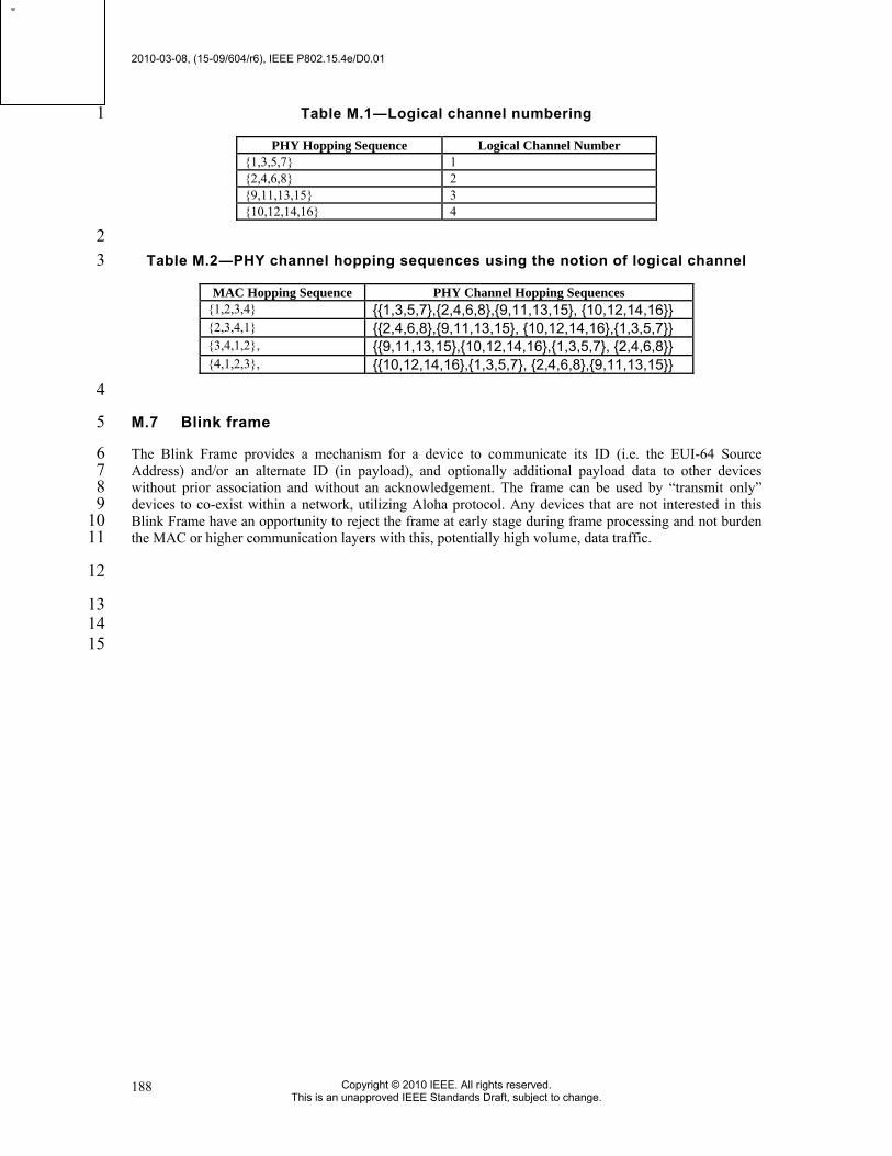
2010-03-08, (15-09/604/r6), IEEE P802.15.4e/D0.01
Copyright © 2010 IEEE. All rights reserved. This is an unapproved IEEE Standards Draft, subject to change.
188
Table M.1―Logical channel numbering 1
PHY Hopping Sequence Logical Channel Number {1,3,5,7} 1 {2,4,6,8} 2 {9,11,13,15} 3 {10,12,14,16} 4
2 Table M.2―PHY channel hopping sequences using the notion of logical channel 3
MAC Hopping Sequence PHY Channel Hopping Sequences {1,2,3,4} {{1,3,5,7},{2,4,6,8},{9,11,13,15}, {10,12,14,16}} {2,3,4,1} {{2,4,6,8},{9,11,13,15}, {10,12,14,16},{1,3,5,7}} {3,4,1,2}, {{9,11,13,15},{10,12,14,16},{1,3,5,7}, {2,4,6,8}} {4,1,2,3}, {{10,12,14,16},{1,3,5,7}, {2,4,6,8},{9,11,13,15}}
4
M.7 Blink frame 5
The Blink Frame provides a mechanism for a device to communicate its ID (i.e. the EUI-64 Source 6 Address) and/or an alternate ID (in payload), and optionally additional payload data to other devices 7 without prior association and without an acknowledgement. The frame can be used by “transmit only” 8 devices to co-exist within a network, utilizing Aloha protocol. Any devices that are not interested in this 9 Blink Frame have an opportunity to reject the frame at early stage during frame processing and not burden 10 the MAC or higher communication layers with this, potentially high volume, data traffic. 11
12
13 14 15
w