ieee standards - draft standard template€¦ · submission page i dave evans, philips 1 march,...
TRANSCRIPT

Submission Page i Dave Evans, Philips
March, 2012 IEEE P802.15-11-0836-05-0004j 1
2
IEEE P802.15 3
Wireless Personal Area Networks 4
5
Project IEEE P802.15 Working Group for Wireless Personal Area Networks (WPANs)
Title TG4j Amendment Draft
Date
Submitted
[15th
March 2012]
Source [Dave Evans]
[Philips, 101 Cambridge Science Park,
Cambridge, UK]
Voice: [+44 1293 886490]
Fax: [ ]
E-mail: [[email protected]]
Re: []
Abstract [This is the draft of the TG4j Amendment]
Purpose [To enable editing of the draft TG4j MBAN amendment.]
Notice This document has been prepared to assist the IEEE P802.15. It is offered as a basis for discussion
and is not binding on the contributing individual(s) or organization(s). The material in this
document is subject to change in form and content after further study. The contributor(s) reserve(s)
the right to add, amend or withdraw material contained herein.
Release The contributor acknowledges and accepts that this contribution becomes the property of IEEE and
may be made publicly available by P802.15.
6
7
8
9
10
11
Draft IEEE P802.15.4j/D1.0, March 2012 (Revision of IEEE Std. 802.15.4-2011)
Copyright © 2012 IEEE. All rights reserved. This is an unapproved IEEE Standards Draft, subject to change.
1
IEEE Standard for 2
Local and metropolitan area networks– 3
Part 15.4: Low-Rate Wireless Personal Area 4
Networks (LR-WPANs) 5
Amendment: Alternative Physical Layer Extension to 6
support Medical Body Area Networks (MBANS) services 7
operating in the 2360-2400 MHz band 8
Sponsor 9
LAN/MAN Standards Committee 10 of the 11 IEEE Computer Society 12
13
IEEE-SA Standards Board 14 15
16
Prepared by the IEEE 802.15 Working Group for Wireless Personal Area Networks 17
Committee IEEE802 18
Copyright © 2012 by the Institute of Electrical and Electronics Engineers, Inc. 19 Three Park Avenue 20 New York, New York 10016-5997, USA 21
All rights reserved. 22
This document is an unapproved draft of a proposed IEEE Standard. As such, this document is subject to 23 change. USE AT YOUR OWN RISK! Because this is an unapproved draft, this document must not be 24 utilized for any conformance/compliance purposes. Permission is hereby granted for IEEE Standards 25 Committee participants to reproduce this document for purposes of international standardization 26 consideration. Prior to adoption of this document, in whole or in part, by another standards development 27 organization, permission must first be obtained from the IEEE Standards Association Department 28 ([email protected]). Other entities seeking permission to reproduce this document, in whole or in part, must 29 also obtain permission from the IEEE Standards Association Department. 30
IEEE Standards Association Department 31 445 Hoes Lane 32 Piscataway, NJ 08854, USA 33
34

Draft IEEE P802.15.4j/D1.0, March 2012 (Revision of IEEE Std. 802.15.4-2011)
Copyright © 2012 IEEE. All rights reserved. This is an unapproved IEEE Standards Draft, subject to change.
Abstract: This amendment defines a physical layer for IEEE 802.15.4 in the 2360 to 2400 MHz 1 band which complies with Federal Communications Commission (FCC) MBAN rules. This 2 amendment defines modifications to the MAC needed to support this new physical layer. 3 4 Keywords: MBANS, medical body area network 5 6
7

Draft IEEE P802.15.4j/D1.0, March 2012 (Revision of IEEE Std. 802.15.4-2011)
Copyright © 2012 IEEE. All rights reserved. This is an unapproved IEEE Standards Draft, subject to change.
IEEE Standards documents are developed within the IEEE Societies and the Standards Coordinating Committees of 1 the IEEE Standards Association (IEEE-SA) Standards Board. The IEEE develops its standards through a consensus 2 development process, approved by the American National Standards Institute, which brings together volunteers 3 representing varied viewpoints and interests to achieve the final product. Volunteers are not necessarily members of the 4 Institute and serve without compensation. While the IEEE administers the process and establishes rules to promote 5 fairness in the consensus development process, the IEEE does not independently evaluate, test, or verify the accuracy 6 of any of the information or the soundness of any judgments contained in its standards. 7
Use of an IEEE Standard is wholly voluntary. The IEEE disclaims liability for any personal injury, property or other 8 damage, of any nature whatsoever, whether special, indirect, consequential, or compensatory, directly or indirectly 9 resulting from the publication, use of, or reliance upon this, or any other IEEE Standard document. 10
The IEEE does not warrant or represent the accuracy or content of the material contained herein, and expressly 11 disclaims any express or implied warranty, including any implied warranty of merchantability or fitness for a specific 12 purpose, or that the use of the material contained herein is free from patent infringement. IEEE Standards documents 13 are supplied ―AS IS.‖ 14
The existence of an IEEE Standard does not imply that there are no other ways to produce, test, measure, purchase, 15 market, or provide other goods and services related to the scope of the IEEE Standard. Furthermore, the viewpoint 16 expressed at the time a standard is approved and issued is subject to change brought about through developments in the 17 state of the art and comments received from users of the standard. Every IEEE Standard is subjected to review at least 18 every five years for revision or reaffirmation, or every ten years for stabilization. When a document is more than five 19 years old and has not been reaffirmed, or more than ten years old and has not been stabilized, it is reasonable to 20 conclude that its contents, although still of some value, do not wholly reflect the present state of the art. Users are 21 cautioned to check to determine that they have the latest edition of any IEEE Standard. 22
In publishing and making this document available, the IEEE is not suggesting or rendering professional or other 23 services for, or on behalf of, any person or entity. Nor is the IEEE undertaking to perform any duty owed by any other 24 person or entity to another. Any person utilizing this, and any other IEEE Standards document, should rely upon his or 25 her independent judgment in the exercise of reasonable care in any given circumstances or, as appropriate, seek the 26 advice of a competent professional in determining the appropriateness of a given IEEE standard. 27
Interpretations: Occasionally questions may arise regarding the meaning of portions of standards as they relate to 28 specific applications. When the need for interpretations is brought to the attention of IEEE, the Institute will initiate 29 action to prepare appropriate responses. Since IEEE Standards represent a consensus of concerned interests, it is 30 important to ensure that any interpretation has also received the concurrence of a balance of interests. For this reason, 31 IEEE and the members of its societies and Standards Coordinating Committees are not able to provide an instant 32 response to interpretation requests except in those cases where the matter has previously received formal consideration. 33 A statement, written or oral, that is not processed in accordance with the IEEE-SA Standards Board Operations Manual 34 shall not be considered the official position of IEEE or any of its committees and shall not be considered to be, nor be 35 relied upon as, a formal interpretation of the IEEE. At lectures, symposia, seminars, or educational courses, an 36 individual presenting information on IEEE standards shall make it clear that his or her views should be considered the 37 personal views of that individual rather than the formal position, explanation, or interpretation of the IEEE. 38
Comments for revision of IEEE Standards are welcome from any interested party, regardless of membership affiliation 39 with IEEE. Suggestions for changes in documents should be in the form of a proposed change of text, together with 40 appropriate supporting comments. Recommendations to change the status of a stabilized standard should include a 41 rationale as to why a revision or withdrawal is required. Comments and recommendations on standards, and requests 42 for interpretations should be addressed to: 43
Secretary, IEEE-SA Standards Board 44
445 Hoes Lane 45
Piscataway, NJ 08854 46
USA 47
Authorization to photocopy portions of any individual standard for internal or personal use is granted by The Institute 48 of Electrical and Electronics Engineers, Inc., provided that the appropriate fee is paid to Copyright Clearance Center. 49 To arrange for payment of licensing fee, please contact Copyright Clearance Center, Customer Service, 222 Rosewood 50 Drive, Danvers, MA 01923 USA; +1 978 750 8400. Permission to photocopy portions of any individual standard for 51 educational classroom use can also be obtained through the Copyright Clearance Center. 52

Draft IEEE P802.15.4j/D1.0, March 2012 (Revision of IEEE Std. 802.15.4-2011)
iv Copyright © 2012 IEEE. All rights reserved.
This is an unapproved IEEE Standards Draft, subject to change.
Introduction 1
This introduction is not part of IEEE P802.15.4j/D00, Draft Standard for Amendment: Alternative Physical Layer 2 Extension to support Medical Body Area Network (MBAN) services operating in the 2360-2400 MHz band. 3
Notice to users 4
Laws and regulations 5
Users of these documents should consult all applicable laws and regulations. Compliance with the 6 provisions of this standard does not imply compliance to any applicable regulatory requirements. 7 Implementers of the standard are responsible for observing or referring to the applicable regulatory 8 requirements. IEEE does not, by the publication of its standards, intend to urge action that is not in 9 compliance with applicable laws, and these documents may not be construed as doing so. 10
Copyrights 11
This document is copyrighted by the IEEE. It is made available for a wide variety of both public and 12 private uses. These include both use, by reference, in laws and regulations, and use in private self-13 regulation, standardization, and the promotion of engineering practices and methods. By making this 14 document available for use and adoption by public authorities and private users, the IEEE does not waive 15 any rights in copyright to this document. 16
Updating of IEEE documents 17
Users of IEEE standards should be aware that these documents may be superseded at any time by the 18 issuance of new editions or may be amended from time to time through the issuance of amendments, 19 corrigenda, or errata. An official IEEE document at any point in time consists of the current edition of the 20 document together with any amendments, corrigenda, or errata then in effect. In order to determine whether 21 a given document is the current edition and whether it has been amended through the issuance of 22 amendments, corrigenda, or errata, visit the IEEE Standards Association web site at 23 http://ieeexplore.ieee.org/xpl/standards.jsp, or contact the IEEE at the address listed previously. 24
For more information about the IEEE Standards Association or the IEEE standards development process, 25 visit the IEEE-SA web site at http://standards.ieee.org. 26
Errata 27
Errata, if any, for this and all other standards can be accessed at the following URL: 28 http://standards.ieee.org/reading/ieee/updates/errata/index.html. Users are encouraged to check this URL 29 for errata periodically. 30
Draft IEEE P802.15.4j/D1.0, March 2012 (Revision of IEEE Std. 802.15.4-2011)
v Copyright © 2012 IEEE. All rights reserved.
This is an unapproved IEEE Standards Draft, subject to change.
Interpretations 1
Current interpretations can be accessed at the following URL: http://standards.ieee.org/reading/ieee/interp/ 2 index.html. 3
Patents 4
[If the IEEE has not received letters of assurance prior to the time of publication, the following notice 5 shall appear:] 6
Attention is called to the possibility that implementation of this standard may require use of subject matter 7 covered by patent rights. By publication of this standard, no position is taken with respect to the existence 8 or validity of any patent rights in connection therewith. The IEEE is not responsible for identifying 9 Essential Patent Claims for which a license may be required, for conducting inquiries into the legal validity 10 or scope of Patents Claims or determining whether any licensing terms or conditions provided in 11 connection with submission of a Letter of Assurance, if any, or in any licensing agreements are reasonable 12 or non-discriminatory. Users of this standard are expressly advised that determination of the validity of any 13 patent rights, and the risk of infringement of such rights, is entirely their own responsibility. Further 14 information may be obtained from the IEEE Standards Association. 15
[The following notice shall appear when the IEEE receives assurance from a known patent holder or 16 patent applicant prior to the time of publication that a license will be made available to all applicants 17 either without compensation or under reasonable rates, terms, and conditions that are demonstrably free 18 of any unfair discrimination.] 19
Attention is called to the possibility that implementation of this standard may require use of subject matter 20 covered by patent rights. By publication of this standard, no position is taken with respect to the existence 21 or validity of any patent rights in connection therewith. A patent holder or patent applicant has filed a 22 statement of assurance that it will grant licenses under these rights without compensation or under 23 reasonable rates, with reasonable terms and conditions that are demonstrably free of any unfair 24 discrimination to applicants desiring to obtain such licenses. Other Essential Patent Claims may exist for 25 which a statement of assurance has not been received. The IEEE is not responsible for identifying Essential 26 Patent Claims for which a license may be required, for conducting inquiries into the legal validity or scope 27 of Patents Claims, or determining whether any licensing terms or conditions provided in connection with 28 submission of a Letter of Assurance, if any, or in any licensing agreements are reasonable or non-29 discriminatory. Users of this standard are expressly advised that determination of the validity of any patent 30 rights, and the risk of infringement of such rights, is entirely their own responsibility. Further information 31 may be obtained from the IEEE Standards Association. 32
33

Draft IEEE P802.15.4j/D1.0, March 2012 (Revision of IEEE Std. 802.15.4-2011)
vi Copyright © 2012 IEEE. All rights reserved.
This is an unapproved IEEE Standards Draft, subject to change.
Participants 1
At the time this draft Amendment was submitted to the IEEE-SA Standards Board for approval, the IEEE 2 P802.15 Working Group had the following membership: 3
Robert F Heile, Chair 4 Rick Alfin, Co-Vice Chair 5
Patrick W. Kinney, Co-Vice Chair and Secretary 6 James P. K. Gilb, Working Group Technical Editor 7
Clint Chaplin, Treasurer 8 9
Raymond Krasinski, Task Group 4j Chair 10 David H. Evans, Task Group 4j Technical Editor and Secretary 11
12 13 The following members of the IEEE 802.15 balloting committee balloting committee voted on this draft. 14 Balloters may have voted for approval, disapproval, or abstention. 15 16 (to be supplied by IEEE) 17 18 Balloter1 19 Balloter2 20 Balloter3 21
Balloter4 22 Balloter5 23 Balloter6 24
Balloter7 25 Balloter8 26 Balloter9 27
28 29 Major contributions besides the chair, secretary and the editor were received from the following 30 individuals: 31 32 Anuj Bahtra 33 Paul Chilton 34 Jin-Meng Ho 35
Suhwook Kim 36 Seung-Hoon Park 37 Ranjeet K. Patro 38
Jaeseung Son 39 Dong Wang 40 Betty Zhao 41
42 43 The following members of the balloting committee balloting committee voted on this draft. Balloters may 44 have voted for approval, disapproval, or abstention. 45 46 (to be supplied by IEEE) 47 48 Balloter1 49 Balloter2 50 Balloter3 51
Balloter4 52 Balloter5 53 Balloter6 54
Balloter7 55 Balloter8 56 Balloter9 57
58 59 60

Draft IEEE P802.15.4j/D1.0, March 2012 (Revision of IEEE Std. 802.15.4-2011)
vii Copyright © 2012 IEEE. All rights reserved.
This is an unapproved IEEE Standards Draft, subject to change.
Contents 1
1. Overview .................................................................................................................................................... 1 2
2. Normative references .................................................................................................................................. 1 3
3. Definitions .................................................................................................................................................. 2 4 3.1 Definitions ........................................................................................................................................... 2 5 3.2 Acronyms and abbreviations ............................................................................................................... 2 6
4. General description ..................................................................................................................................... 2 7
5. MAC protocol ............................................................................................................................................. 2 8 5.1 MAC functional description ................................................................................................................ 2 9
5.1.1 Channel access ............................................................................................................................. 2 10 5.1.2 Starting and maintaining PANs .................................................................................................... 2 11 5.1.3 Association and disassocisation ................................................................................................... 6 12 5.1.4 Synchronization ........................................................................................................................... 8 13 5.1.5 Transaction handling .................................................................................................................... 8 14 5.1.6 Transmission, reception, and acknowledgement .......................................................................... 8 15 5.1.7 GTS allocation and management ................................................................................................. 8 16
5.2 MAC frame format .............................................................................................................................10 17 5.2.1 General MAC frame format ........................................................................................................10 18 5.2.2 Format of individual frame types ................................................................................................10 19
5.3 MAC command frames.......................................................................................................................11 20 5.3.1 Association request command.....................................................................................................12 21 5.3.2 Association response command ..................................................................................................12 22 5.3.3 Disassociation notification command .........................................................................................12 23 5.3.4 Data request command ................................................................................................................12 24 5.3.5 PAN ID conflict notification command ......................................................................................12 25 5.3.6 Orphan notification command.....................................................................................................12 26 5.3.7 Beacon request command ...........................................................................................................12 27 5.3.8 Coordinator realignment command .............................................................................................12 28 5.3.9 GTS request command ................................................................................................................12 29 5.3.10 Channel switch notification command ......................................................................................14 30 5.3.11 Grant association proxy request ................................................................................................15 31 5.3.12 Grant association proxy response ..............................................................................................16 32 5.3.13 Association proxy request .........................................................................................................17 33 5.3.14 Association proxy response ......................................................................................................18 34 5.3.15 Coordinator switch ....................................................................................................................19 35
6. MAC services ............................................................................................................................................21 36 6.1 Overview ............................................................................................................................................21 37 6.2 MAC management service .................................................................................................................21 38
6.2.1 Common requirements for MLME primitives ............................................................................21 39 6.2.2 Association primitives.................................................................................................................21 40 6.2.3 Disassociation primitives ............................................................................................................22 41 6.2.4 Communications notification primitives .....................................................................................22 42 6.2.5 Primitives for reading PIB attributes ...........................................................................................22 43 6.2.6 GTS management primitives.......................................................................................................22 44 6.2.7 Primitives for orphan notification ...............................................................................................22 45 6.2.8 Primitives for resetting the MAC sublayer .................................................................................22 46 6.2.9 Primitives for specifying the receiver enable time ......................................................................22 47

Draft IEEE P802.15.4j/D1.0, March 2012 (Revision of IEEE Std. 802.15.4-2011)
viii Copyright © 2012 IEEE. All rights reserved.
This is an unapproved IEEE Standards Draft, subject to change.
6.2.10 Primitives for channel scanning ................................................................................................22 1 6.2.11 Primitives for writing PIB attributes .........................................................................................22 2 6.2.12 Primitives for updating the superframe configuration...............................................................22 3 6.2.13 Primitives for synchronizing with a coordinator .......................................................................22 4 6.2.14 Primitives for requesting data from a coordinator .....................................................................22 5 6.2.15 Primitives for specifying dynamic preamble.............................................................................22 6 6.2.16 Primitives for channel sounding ................................................................................................22 7 6.2.17 Primitives for ranging calibration (for UWB PHYs) ................................................................22 8 6.2.18 Channel switch notification primitives .....................................................................................22 9 6.2.19 Periodic GTS management primitives ......................................................................................26 10 6.2.20 Grant association proxy notification primitives ........................................................................28 11 6.2.21 Grant association proxy notification primitives ........................................................................32 12 6.2.22 Coordinator switch notification primitives ...............................................................................35 13
6.3 MAC data service ...............................................................................................................................39 14 6.4 MAC constants and PIB attributes......................................................................................................39 15
6.4.1 MAC constants ............................................................................................................................39 16 6.4.2 MAC PIB attributes ....................................................................................................................39 17
7. Security ......................................................................................................................................................40 18
8. General PHY requirements ........................................................................................................................40 19 8.1 General requirements and definitions .................................................................................................40 20
8.1.1 Operating frequency range ..........................................................................................................40 21 8.1.2 Channel assignments ...................................................................................................................40 22
9. PHY services .............................................................................................................................................41 23
10. O-QPSK PHY ..........................................................................................................................................41 24 10.1 PPDU format ....................................................................................................................................41 25 10.2 Modulation and spreading ................................................................................................................41 26
10.2.1 Data rate ....................................................................................................................................41 27 10.2.2 Reference modulator diagram ...................................................................................................41 28 10.2.3 Bit-to-symbol mapping .............................................................................................................41 29 10.2.4 Symbol-to-chip mapping ...........................................................................................................41 30 10.2.5 O-QPSK modulation .................................................................................................................42 31 10.2.6 Pulse shape ................................................................................................................................42 32 10.2.7 Chip transmission order ............................................................................................................42 33
10.3 O-QPSK PHY RF requirements .......................................................................................................42 34 10.3.1 Operating frequency range ........................................................................................................42 35 10.3.2 Transmit power spectral density (PSD) mask ...........................................................................43 36 10.3.3 Symbol rate ...............................................................................................................................43 37 10.3.4 Receiver sensitivity ...................................................................................................................43 38 10.3.5 Receiver interference rejection .................................................................................................43 39
Annex I ..........................................................................................................................................................44 40 Channel bitmap .........................................................................................................................................44 41
42
43
IEEE P802.15.4j/D1.0, March 2012
1 Copyright © 2012 IEEE. All rights reserved.
This is an unapproved IEEE Standards Draft, subject to change.
1
IEEE Standard for 2
Local and metropolitan area networks– 3
Part 15.4: Low-Rate Wireless Personal Area 4
Networks (LR-WPANs) 5
Amendment: Alternative Physical Layer Extension to 6
support Medical Body Area Networks (MBANS) services 7
operating in the 2360-2400 MHz band 8
9
NOTE—The editing instructions contained in this amendment define how to merge the material contained 10 therein into the existing base standard and its amendments to form the comprehensive standard. 11
The editing instructions are shown in bold italic. Four editing instructions are used: change, delete, insert, 12 and replace. Change is used to make corrections in existing text or tables. The editing instruction specifies 13 the location of the change and describes what is being changed by using strikethrough (to remove old 14 material) and underscore (to add new material). Delete removes existing material. Insert adds new material 15 without disturbing the existing material. Deletions and insertions may require renumbering. If so, 16 renumbering instructions are given in the editing instruction. Replace is used to make changes in figures or 17 equations by removing the existing figure or equation and replacing it with a new one. Editing instructions, 18 change markings, and this NOTE will not be carried over into future editions because the changes will be 19 incorporated into the base standard. 20
21
1. Overview 22
2. Normative references 23
The following referenced documents are indispensable for the application of this document (i.e., they must 24 be understood and used, so each referenced document is cited in text and its relationship to this document is 25 explained). For dated references, only the edition cited applies. For undated references, the latest edition of 26 the referenced document (including any amendments or corrigenda) applies. 27
Insert the following new reference alphabetically into Clause 2: 28

IEEE P802.15.4j/D1.0, March 2012
2 Copyright © 2012 IEEE. All rights reserved.
This is an unapproved IEEE Standards Draft, subject to change.
IEEE Std 802.1D-2004, IEEE Standard for Local and Metropolitan Area Networks: Media Access Control 1 (MAC) Bridges
1. 2
3. Definitions 3
3.1 Definitions 4
3.2 Acronyms and abbreviations 5
Insert the following acronym alphabetically into 3.2: 6
MBANS medical body area network services 7
4. General description 8
5. MAC protocol 9
5.1 MAC functional description 10
5.1.1 Channel access 11
5.1.2 Starting and maintaining PANs 12
5.1.2.1 Scanning through channels 13
5.1.2.2 PAN identifier conflict resolution 14
5.1.2.3 Starting and realigning a PAN 15
5.1.2.3.1 Starting a PAN 16
5.1.2.3.2 Realigning a PAN 17
1 IEEE publications are available from the Institute of Electrical and Electronics Engineers, 445 Hoes Lane, P.O. Box 1331,
Piscataway, NJ 08855-1331, USA (http://standards.ieee.org).

IEEE P802.15.4j/D1.0, March 2012
3 Copyright © 2012 IEEE. All rights reserved.
This is an unapproved IEEE Standards Draft, subject to change.
5.1.2.3.3 Realignment in a PAN 1
5.1.2.3.4 Updating superframe configuration and channel PIB attributes 2
Insert the following after 5.1.2.3.4: 3
5.1.2.3.5 Channel switch notification 4
The channel switch notification procedure is initiated by the next higher layer by issuing the MLME-5 CHANNELSWITCH.request primitive, as described in 6.2.18.1, to the MLME. 6
When a coordinator wants one of its associated devices to switch its operating channel at a specific time, 7 the MLME of the coordinator shall send the channel switch notification command in the manner specified 8 by the TxIndirect parameter of the MLME-CHANNELSWITCH.request primitive previously sent by the 9 next higher layer. If TxIndirect is TRUE, the MLME of the coordinator shall send the channel switch 10 notification command to the device using indirect transmission; i.e. the channel switch notification 11 command frame shall be added to the list of pending transactions stored on the coordinator and extracted at 12 the discretion of the device concerned using the method described in 5.1.6.3. If the command frame is not 13 successfully extracted by the device, the coordinator shall consider the device disassociated. Otherwise, the 14 MLME shall send the channel switch notification command to the device directly. In this case, if the 15 channel switch notification command cannot be sent due to a channel access failure, the MAC sublayer 16 shall notify the next higher layer. 17
Upon successful transmission of the channel switch command, the MAC sublayer shall issue the MLME-18 CHANNELSWITCH.confirm primitive with a status of SUCCESS. 19
If a device has received the channel switch command, as defined in 5.3.10, from the coordinator, the 20 MLME shall issue the MLME-CHANNELSWITCH.indication primitive with the NewPANID, 21 CoordinatorAddress, RemainingTime, ChannelNumber and ChannelPage parameters set to the respective 22 field in the channel switch command. 23
Figure 16a illustrates the sequence necessary for a coordinator in a beacon-enabled PAN to successfully 24 transmit channel switch notification command to a device using indirect transmission. 25
26

IEEE P802.15.4j/D1.0, March 2012
4 Copyright © 2012 IEEE. All rights reserved.
This is an unapproved IEEE Standards Draft, subject to change.
Device next higher layer
Device MLME
CoordinatorMLME
Coordinatornext higher layer
MLME-CHANNELSWITCH.request
(TxIndirect = TRUE)
Beacon (with data pending)
Data request
Acknowledgement
Channel switch notification
Acknowledgement
MLME-CHANNELSWITCH.indication
MLME-CHANNELSWITCH.confirm
(SUCCESS)
1 2
Figure 16a—Message sequence chart for channel switch notification initiated by a 3 coordinator, using indirect transmission, in a beacon-enabled PAN 4
5
5.1.2.4 Beacon generation 6
5.1.2.5 Device discovery 7
Insert the following after 5.1.2.5: 8
5.1.2.6 Coordinator switch 9
A PAN coordinator can switch the devices that are associated to its PAN to another coordinator by using 10 the coordinator switch and device re-alignment commands. The PAN coordinator shall first broadcast a 11 coordinator switch request on a channel using the coordinator switch request command described in 5.3.15 12 indicating the number of devices that it wishes to switch. The number of devices defines the devices that 13 are associated with its PAN. If another coordinator has the resources and is able to accept the number of 14 devices, it may respond to the broadcast coordinator switch request by sending a coordinator switch 15 response command to the PAN coordinator confirming that it is able to accept the defined number of 16 devices. The time for which the PAN coordinator listens for responses after transmitting the coordinator 17 request command is beyond the scope of this standard. The PAN coordinator shall repeat the broadcast of 18 the coordinator switch request on all of the available channels. The sequence of coordinator switch 19 broadcast request and coordinator switch response messages are shown in Figure 16b. 20

IEEE P802.15.4j/D1.0, March 2012
5 Copyright © 2012 IEEE. All rights reserved.
This is an unapproved IEEE Standards Draft, subject to change.
1 2
Figure 16b – Coordinator switch broadcast and response 3 4
The PAN coordinator shall then select a new coordinator and confirm to the new coordinator using the 5 coordinator switch request command that the new coordinator shall accept the association of the number of 6 device defined in the command. The process for the selection of a new coordinator is beyond the scope of 7 this standard. Once the PAN coordinator has received a successful confirmation of the coordinator 8 switching request command from the new coordinator, it shall send a channel switch notification command 9 to its devices containing the PAN ID and the extended address of the new coordinator and the channel 10 number and channel page that it is operating on. On receiving the channel switch notification command, the 11 devices shall attempt to associate with the new coordinator whose details are provided in this command and 12 shall do so without performing a channel scan. The sequence of coordinator switch selection and channel 13 switch notification messages are shown in Figure 16c. 14
15

IEEE P802.15.4j/D1.0, March 2012
6 Copyright © 2012 IEEE. All rights reserved.
This is an unapproved IEEE Standards Draft, subject to change.
1 2
3 Figure 16c – Coordinator switch selection and channel switch notification 4
5
5.1.3 Association and disassocisation 6
5.1.3.1 Association 7
5.1.3.2 Disassociation 8
Insert the following after5.1.3.2: 9
5.1.3.3 Association proxy 10
A device shall attempt a request for grant of association proxy after having first associated with a suitable 11 PAN. A coordinator shall allow a grant of association proxy only if macAssociationPermit is set to TRUE. 12 Similarly, a device shall attempt a request for grant of association proxy only if the coordinator is currently 13 allowing association, as indicated in the results of the scanning procedure. If a coordinator with 14 macAssociationPermit set to FALSE receives a grant association proxy request command from a device, 15 the coordinator shall ignore the command. 16
The MAC sublayer shall initiate the grant association proxy procedure by sending a grant association proxy 17 request command, as described in 5.3.11, to the coordinator of the PAN; if the grant association proxy 18 request command cannot be sent due to a channel access failure, the MAC sublayer shall notify the next 19 higher layer. 20
The acknowledgment to a grant association proxy request command does not mean that the device has 21 associated. The coordinator needs time to determine whether the current resources available on the PAN 22 are sufficient to allow other devices to associate. The coordinator shall make this decision within 23 macResponseWaitTime of receiving this command. If the coordinator has sufficient resources, it shall 24

IEEE P802.15.4j/D1.0, March 2012
7 Copyright © 2012 IEEE. All rights reserved.
This is an unapproved IEEE Standards Draft, subject to change.
allocate a set of short addresses to the devices, and its MAC sublayer shall generate a grant association 1 proxy response command, as described in 5.3.12. The command shall specify the number of devices that 2 have been allocated a short address, the actual short addresses that the devices may use and a status 3 indicating a successful grant of proxy association. If the coordinator has insufficient resources its MLME 4 shall generate a grant association proxy response command containing a status indicating a failure, as 5 defined in Table 6. The grant association proxy response command shall be sent to the device requesting 6 the grant of association proxy using indirect transmission; i.e., the grant association proxy response 7 command frame shall be added to the list of pending transactions stored on the coordinator and extracted at 8 the discretion of the device concerned using the method described in 5.1.6.3. 9
On receipt of the acknowledgment to the grant association proxy request command, the device shall wait 10 for at most macResponseWaitTime from when the command is received for the coordinator to make its 11 grant of association proxy decision; the PIB attribute macResponseWaitTime is a network-topology-12 dependent parameter and shall be set to match the specific requirements of the network that a device is 13 trying to join. If the device is tracking the beacon, it shall attempt to extract the grant association proxy 14 response command from the coordinator whenever it is indicated in the beacon frame. If the device is not 15 tracking the beacon, it shall attempt to extract the grant association proxy response command from the 16 coordinator after macResponseWaitTime. If the device does not extract a grant association proxy response 17 command frame from the coordinator within macResponseWaitTime, the MLME shall issue the MLME-18 GRANTASSOCIATIONPROXY.confirm primitive, as described in 6.2.20.4, with a status of NO_DATA, 19 and the request for grant of association proxy attempt shall be deemed a failure. In this case, the device 20 shall terminate any tracking of the beacon, by issuing an MLME-SYNC.request primitive, as described in 21 6.2.13.1, with the TrackBeacon parameter set to FALSE. 22
A device shall attempt a request for an association proxy after obtaining the extended address and 23 capability information for each of the devices for which it has requested a grant of association proxy. The 24 method for obtaining this information from the devices is outside the scope of this standard. 25
The MAC sublayer shall initiate the association proxy procedure by sending an association proxy request 26 command, as described in 5.3.13, to the coordinator of the PAN. 27
On receipt of an association proxy request command, the coordinator shall update the device-specific 28 information for the allocated short address with the device extended address and the device capability 29 information. If the coordinator finds that the device was previously associated with its PAN, it shall replace 30 all previously obtained device-specific information. If the coordinator has successfully updated the device 31 information, it shall respond with an association proxy response command indicating success. 32
A message sequence chart for grant of an association proxy is illustrated in Figure 19a. 33
34

IEEE P802.15.4j/D1.0, March 2012
8 Copyright © 2012 IEEE. All rights reserved.
This is an unapproved IEEE Standards Draft, subject to change.
Device next higher layer
Device MLME
CoordinatorMLME
Coordinatornext higher layer
MLME-GRANTASSOCIATION.request
Acknowledgement
Grant association proxy request
MLME-GRANTASSOCIATION.indication
MLME-GRANTASSOCIATION.response
Acknowledgement
Data request
Grant association proxy response
Acknowledgement
MLME-GRANTASSOCIATION.confirm
1 2
Figure 19a—Message sequence chart for grant of an association proxy 3 4
A message sequence chart for an association proxy is illustrated in Figure 19b. 5
Device next higher layer
Device MLME
CoordinatorMLME
Coordinatornext higher layer
MLME-ASSOCIATIONPROXY.request
Acknowledgement
Association proxy request
MLME-ASSOCIATIONPROXY.indication
MLME-ASSOCIATIONPROXY.confirm
Acknowledgement
Data request
Association proxy response
Acknowledgement
6 7
Figure 19b—Message sequence chart for an association proxy 8 9
5.1.4 Synchronization 10
5.1.5 Transaction handling 11
5.1.6 Transmission, reception, and acknowledgement 12
5.1.7 GTS allocation and management 13

IEEE P802.15.4j/D1.0, March 2012
9 Copyright © 2012 IEEE. All rights reserved.
This is an unapproved IEEE Standards Draft, subject to change.
5.1.7.1 CAP maintenance 1
5.1.7.2 GTS allocation 2
Insert after the second paragraph: 3
To request the allocation of a new periodic GTS, the MLME shall send the periodic GTS request command, 4 as described in 5.3.9, to the PAN coordinator. The Characteristics Type field of the request shall be set to 5 one, and the length, direction, start frame and period exponent fields shall be set according to the desired 6 characteristics of the required periodic GTS. 7
Insert after the fifth paragraph: 8
When the PAN coordinator determines whether capacity is available for the requested periodic GTS, it 9 shall generate a periodic GTS descriptor with the requested specifications and the short address of the 10 requesting device. If the periodic GTS is allocated successfully, the PAN coordinator shall set the start slot 11 in the periodic GTS descriptor to the superframe slot at which the periodic GTS begins and the GTS BSN 12 in the periodic GTS descriptor to the number of remaining superframes for the first allocated periodic GTS 13 slot. In addition, the PAN coordinator shall notify the next higher layer of the new periodic GTS. This 14 notification is achieved when the MLME of the PAN coordinator issues the MLME-PERIODIC-15 GTS.indication primitive, as described in 6.2.19.3 with the characteristics of the allocated periodic GTS. If 16 there is not sufficient capacity to allocate the requested GTS, the start slot and GTS BSN shall be set to 17 zero. The PAN coordinator shall then include this periodic GTS descriptor in its beacon and update the 18 GTS Specification field of the beacon frame accordingly. The PAN coordinator shall also update the Final 19 CAP Slot field of the Superframe Specification field of the beacon frame, indicating the final superframe 20 slot utilized by the decreased CAP. The periodic GTS descriptor shall remain in the beacon frame for 21 aGTSDescPersistenceTime superframes, after which it shall be removed automatically. The PAN 22 coordinator shall be allowed to reduce its CAP below aMinCAPLength to accommodate the temporary 23 increase in the beacon frame length due to the inclusion of the periodic GTS descriptor. 24
5.1.7.3 GTS usage 25
5.1.7.4 GTS deallocation 26
Insert after the first paragraph: 27
A device is instructed to request the deallocation of an existing periodic GTS through the MLME-28 PERIODIC-GTS.request primitive, as described in 6.2.19.1, using the characteristics of the periodic GTS it 29 wishes to deallocate. From this point onward, the periodic GTS to be deallocated shall not be used by the 30 device, and its stored characteristics shall be reset. 31
Change and insert in the second paragraph as shown: 32
To request the deallocation of an existing GTS, the MLME shall send the GTS request command, as 33 described in 5.3.9, to the PAN coordinator. To request the deallocation of an existing periodic GTS, the 34 MLME shall send the periodic GTS request command, as described in 5.3.9, to the PAN coordinator. The 35 Characteristics Type field of either the GTS Characteristics field or the Periodic GTS Characteristics field 36 of the request shall be set to zero (i.e., GTS deallocation), and the length and direction fields shall be set 37 according to the characteristics of the GTS to deallocate. On receipt of the acknowledgment to either the 38 GTS request command or the periodic GTS request command, the MLME shall notify the next higher layer 39 of the deallocation. This notification is achieved when either the MLME issues the MLME-GTS.confirm 40 primitive, as described in 6.2.6.2, with a status of SUCCESS and a GTSCharacteristics parameter with its 41
IEEE P802.15.4j/D1.0, March 2012
10 Copyright © 2012 IEEE. All rights reserved.
This is an unapproved IEEE Standards Draft, subject to change.
Characteristics Type field set to zero or when the MLME issues the MLME-PERIODIC-GTS.confirm 1 primitive, as described in 6.2.19.2, with a status of SUCCESS and a PeriodicGTSCharacteristics parameter 2 with its Characteristics Type field set to zero. If either the GTS request command or the periodic GTS 3 request command is not received correctly by the PAN coordinator, it shall determine that the device has 4 stopped using either its GTS or its periodic GTS by the procedure described in 5.1.7.6. 5
5.1.7.5 GTS reallocation 6
5.1.7.6 GTS expiration 7
Insert at the end of 5.1.7.6: 8
The MLME of the PAN coordinator shall attempt to detect when a device has stopped using a periodic 9 GTS using the following rules: 10
For a transmit periodic GTS, the MLME of a PAN coordinator shall assume that a device is no 11 longer using its periodic GTS if a data frame is not received from the device in the GTS at least 12 every 2 × m superframes, where m is defined below. 13
For a receive periodic GTS, the MLME of the PAN coordinator shall assume that a device is no 14 longer using its periodic GTS if an acknowledgment frame is not received from the device at least 15 every 2 × m superframes. If the data frames sent in the GTS do not require acknowledgment 16 frames, the MLME of the PAN coordinator will not be able to detect whether a device is using its 17 receive periodic GTS. However, the PAN coordinator is capable of deallocating the periodic GTS 18 at any time. 19
The value of m is defined as follows: 20
m = P * 2(8-macBeaconOrder) 0 ≤ macBeaconOrder ≤ 8 21
m = P 9 ≤ macBeaconOrder ≤ 14 22
where P is defined in 5.3.9.3. 23
5.2 MAC frame format 24
5.2.1 General MAC frame format 25
5.2.2 Format of individual frame types 26
5.2.2.1 Beacon frame format 27
5.2.2.1.1 Beacon frame MHR fields 28
5.2.2.1.2 Superframe Specification field 29

IEEE P802.15.4j/D1.0, March 2012
11 Copyright © 2012 IEEE. All rights reserved.
This is an unapproved IEEE Standards Draft, subject to change.
5.2.2.1.3 GTS Specification field 1
Change and insert in figure 42 as shown: 2
Bits: 0-2 3-5 6 6
GTS Descriptor Count Reserved Periodic GTS Permit GTS Permit
3 Figure 42–Format of the GTS Specification field 4
5
Insert at the end of 5.2.2.1.3: 6
The Periodic GTS Permit field shall be set to one if macPeriodicGTSPermit is equal to TRUE (i.e., the 7 PAN coordinator is accepting periodic GTS requests). Otherwise, the Periodic GTS Permit field shall be set 8 to zero. 9
5.2.2.1.4 GTS Directions field 10
5.2.2.1.5 GTS List field 11
Insert at the end of 5.2.2.1.5: 12
If a GTS descriptor represents a periodic GTS (i.e. the GTS descriptor corresponds to a periodic GTS 13 request), the GTS Length field shall contain the four least significant bits of the macBSN indicating the first 14 superframe that the periodic GTS is available for the addressed device. 15
5.3 MAC command frames 16
Insert and change as shown in Table 5: 17
Table 5–MAC command frames 18 19
Command frame
identifier Command frame Tx Rx Subclause
0x0a Channel switch notification 5.3.10
0x0b Grant association proxy request 5.3.11
0x0c Grant association proxy response 5.3.12
0x0d Association proxy request 5.3.13
0x0e Association proxy response 5.3.14
0x0f Coordinator switch request 5.3.15.1
0x1a Coordinator switch response 5.3.15.2
0x1b-0xff Reserved -
20

IEEE P802.15.4j/D1.0, March 2012
12 Copyright © 2012 IEEE. All rights reserved.
This is an unapproved IEEE Standards Draft, subject to change.
5.3.1 Association request command 1
5.3.2 Association response command 2
5.3.2.1 MHR fields 3
5.3.2.2 Short Address field 4
5.3.2.3 Association Status field 5
Insert and change as shown in Table 6: 6
Table 6–Valid values of the Association Status field 7 8
Association Status Description
0x03-0x7f0x0f Reserved
0xa0-0xbf Number of allocated device addresses where the number
is offset by 0xa0.
0xc0-0x7f Reserved.
9
5.3.3 Disassociation notification command 10
5.3.4 Data request command 11
5.3.5 PAN ID conflict notification command 12
5.3.6 Orphan notification command 13
5.3.7 Beacon request command 14
5.3.8 Coordinator realignment command 15
5.3.9 GTS request command 16
Insert as shown in the first paragraph of 5.3.9 as follows: 17
The GTS request command is used by an associated device that is requesting the allocation of either a new 18 GTS or a new periodic GTS or the deallocation of either an existing GTS or an existing periodic GTS from 19 the PAN coordinator. Only devices that have a short address less than 0xfffe shall send this command. 20

IEEE P802.15.4j/D1.0, March 2012
13 Copyright © 2012 IEEE. All rights reserved.
This is an unapproved IEEE Standards Draft, subject to change.
Change and insert in Figure 58: 1
Octets: 7 1 1/2
MHR fields Command Frame Identifier GTS Characteristics/
Periodic GTS Characteristics
2 Figure 58–GTS request command format 3
5.3.9.1 MHR fields 4
5.3.9.2 GTS Characteristics field 5
Insert after 5.3.9.2: 6
5.3.9.3 Periodic GTS Characteristics field 7
When the GTS request command is used by an associated device that is requesting the allocation of a new 8 periodic GTS or the deallocation of an existing periodic GTS from the PAN coordinator, the Periodic GTS 9 Characteristics field shall be included. 10
The Periodic GTS Characteristics field shall be formatted as illustrated in Figure 59a. 11
12
Bits: 0-3 4 5 6-7 8-11 12-14 15
GTS Length GTS Direction Characteristic
Type Reserved Start Frame
GTS Period
Exponent Reserved
13 Figure 59a–Periodic GTS Characteristic field format 14
15
The GTS Length field shall contain the number of superframe slots being requested for the periodic GTS. 16
The GTS Direction field shall be set to one if the periodic GTS is to be a receive-only periodic GTS. 17 Conversely, this field shall be set to zero if the GTS is to be a transmit-only periodic GTS. GTS direction is 18 defined relative to the direction of data frame transmissions by the device. 19
The Characteristics Type field shall be set to one if the characteristics refer to a periodic GTS allocation or 20 zero if the characteristics refer to a periodic GTS deallocation. 21
The Start Frame field shall contain the value S, 0 ≤ S ≤ 7, which indicates the first periodic GTS for the 22 requesting device is being requested to occur in a superframe no later than (S+1) superframes after the 23 current superframe. 24
The GTS Period Exponent field shall specify the value, N, and this shall be used to define the period P, in 25 superframes that is being requested for the periodic GTS. 26
The value of P is defined as follows: 27
P = 2(N+1)
for 0 ≤ N ≤ 7 28

IEEE P802.15.4j/D1.0, March 2012
14 Copyright © 2012 IEEE. All rights reserved.
This is an unapproved IEEE Standards Draft, subject to change.
Insert after 5.3.9: 1
5.3.10 Channel switch notification command 2
The channel switch notification command is used by a device to notify another device to switch a channel 3 at certain time. In MBANS, this command shall only be sent by a PAN coordinator. All devices shall be 4 capable of receiving this command. 5
This command is optional. 6
The channel switch notification command shall be formatted as illustrated in Figure 59b. 7
8
Octets: variable 1 variable 1 1
MHR fields Command Frame
Identifier
Standard Dependent
Information
Channel
Number
Channel
Page
9 Figure 59b–Channel switch notification command format 10
5.3.10.1 MHR fields 11
The Destination Addressing Mode field and the Source Addressing Mode field shall be set to indicate 12 extended addressing for MBANS devices. 13
The Frame Pending field shall be set to zero and ignored upon reception. The AR field shall be set to one. 14 The Frame Version field shall be set as specified in 5.2.3. 15
For MBANS devices, the Destination PAN Identifier field shall contain the broadcast PAN identifier. The 16 Destination Address field shall contain the extended address of the destination device. The Source PAN 17 Identifier field shall contain the value of macPANId, and the Source Address field shall contain the value 18 of macExtendedAddress. 19
5.3.10.2 Standard Dependent Information 20
5.3.10.2.1 MBANS information 21
The MBANS information is formatted as illustrated in figure 59c. 22
Octets: 2 2/8 2
New PAN ID Coordinator Address Remaining Time
23 Figure 59c–MBANS information format 24
5.3.10.2.1.1 New PAN ID field 25
The New PAN ID field shall contain the PAN ID of the PAN coordinator that operates in the channel 26 specified in the Channel Number field and Channel Page field. The receiving device is requested to 27 associate with the PAN coordinator for the following communication after channel switching. 28

IEEE P802.15.4j/D1.0, March 2012
15 Copyright © 2012 IEEE. All rights reserved.
This is an unapproved IEEE Standards Draft, subject to change.
5.3.10.2.1.2 Coordinator Address field 1
The Coordinator Address field shall contain the coordinator address of the PAN coordinator that operates in 2 the channel specified in the Channel Number field and Channel Page field. The coordinator address field 3 shall contain either the coordinator short address or coordinator extended address. 4
5.3.10.2.1.3 Remaining Time field 5
The Remaining Time field shall contain the remaining time in minutes after which the channel switching 6 shall occur. 7
5.3.10.3 Channel Number field 8
The Channel Number field shall contain the channel number that the initiating device intends to use for the 9 following communication, and the receiving device is requested to switch to this channel number. 10
5.3.10.4 Channel Page field 11
The Channel Page field shall contain the channel page that the initiating device intends to use for the 12 following communication, and the receiving device is requested to switch to one channel of this channel 13 page. 14
Insert: 15
5.3.11 Grant association proxy request 16
The grant association proxy request command allows a FFD to associate a number of RFDs to a PAN 17 coordinator. 18
Only FFDs shall be capable of transmitting and receiving this command. The FFD shall be associated with 19 the PAN coordinator before using the grant association proxy request command. 20
This command is optional. 21
The grant association proxy request command shall be formatted as illustrated in Figure 59d. 22
Octets: variable 1 1
MHR fields Command Frame Identifier Device Number
23 Figure 59d – Grant association proxy request command format 24
5.3.11.1 MHR fields 25
The Destination Addressing Mode field shall be set to indicate long addressing. The Source Addressing 26 Mode field shall be set to indicate long addressing. 27
The Frame Pending field shall be set to zero and ignored upon reception and the AR field shall be set to 28 one. 29

IEEE P802.15.4j/D1.0, March 2012
16 Copyright © 2012 IEEE. All rights reserved.
This is an unapproved IEEE Standards Draft, subject to change.
The Destination PAN Identifier field shall contain the identifier of the PAN to which the grant association 1 proxy is requested. The Destination Address field shall contain the address from the beacon frame that is 2 transmitted by the coordinator to which the grant associated proxy request command is being sent. The 3 Source PAN Identifier field shall contain the broadcast PAN identifier. The Source Address field shall 4 contain the value of macExtendedAddress. 5
5.3.11.2 Device Number fields 6
The Device Number field shall be formatted as illustrated in Figure 59e. 7
Bits: 0-4 5-7
Number of Devices Reserved
8 Figure 59e–Device Number field format 9
10
The Number of Devices shall be set to indicate the total number of devices for which device short 11 addresses are being requested. 12
5.3.12 Grant association proxy response 13
The grant association proxy response command allows a PAN coordinator to communicate the results of a 14 grant association proxy attempt back to the device requesting a grant association proxy. 15
This command shall only be sent by the PAN coordinator to a FFD that is currently trying to request a grant 16 association proxy. 17
Only FFDs shall be capable of receiving this command. 18
The grant association proxy response command shall be formatted as illustrated in Figure 59f. 19
Octets:
variable 1 1 2*A 1
MHR fields
Command
Frame
Identifier
Number of
Allocated Short
Addresses (A)
Short
Address 1 …
Short
Address A
Association
Status
20
Figure 59f–Grant association proxy response command format 21 22
5.3.12.1 MHR fields 23
The Destination Addressing Mode and the Source Addressing Mode fields shall each be set to indicate 24 extended addressing. 25
The Frame Pending field shall be set to zero and ignored upon reception and the AR field shall be set to 26 one. 27

IEEE P802.15.4j/D1.0, March 2012
17 Copyright © 2012 IEEE. All rights reserved.
This is an unapproved IEEE Standards Draft, subject to change.
The PAN ID Compression field shall be set to one. In accordance with this value of the PAN ID 1 Compression field, the Destination PAN ID field shall contain the value of macPANId, while the Source 2 PAN ID field shall be omitted. 3
The Destination Address field shall contain the extended address of the device requesting association. The 4 Source Address field shall contain the value of macExtendedAddress. 5
5.3.12.2 Number of Allocated Short Addresses field 6
If the coordinator is able to associate a number of devices to its PAN, this field shall contain the number, A, 7 of short addresses that the coordinator is able to allocate, where 1 ≤ A ≤ 32. 8
5.3.12.3 Short Address fields 9
The number of short address fields shall be equal to A, the number of short addresses that the coordinator 10 was able to allocate. These fields shall contain the short addresses that the devices shall use in their 11 communications on the PAN until they are disassociated. 12
5.3.12.4 Association Status field 13
Valid values of the Association Status field are defined in 5.3.2.3 and Table 6. 14
5.3.13 Association proxy request 15
The association proxy request command allows a FFD to update a PAN coordinator with the extended 16 addresses and the Capability Information of the RFDs that have been associated using the grant association 17 proxy request and response commands. 18
Only FFDs shall be capable of transmitting and receiving this command. 19
This command is optional. 20
The association proxy request command shall be formatted as illustrated in Figure 59g. 21
Octets: variable 1 2 8 1
MHR fields Command Frame
Identifier
Device Short
Address
Device Extended
Address
Capability
Information
22
Figure 59g–Association proxy request command format 23
5.3.13.1 MHR fields 24
The Destination Addressing Mode field shall be set to indicate long addressing. The Source Addressing 25 Mode field shall be set to indicate long addressing. 26
The Frame Pending field shall be set to zero and ignored upon reception and the AR field shall be set to 27 one. 28

IEEE P802.15.4j/D1.0, March 2012
18 Copyright © 2012 IEEE. All rights reserved.
This is an unapproved IEEE Standards Draft, subject to change.
The Destination PAN Identifier field shall contain the identifier of the PAN to which the association proxy 1 is requested. 2
5.3.13.2 Device Short Address 3
The Device Short Address field shall contain the short address of the device whose extended address and 4 Capability Information is being transferred to the PAN coordinator. 5
5.3.13.3 Device Extended Address 6
The Device Extended Address field shall contain the extended address of the device whose information is 7 being updated in the PAN coordinator. 8
5.3.13.4 Capability Information field 9
The Capability Information field shall contain the information of the device whose information is being 10 updated in the PAN coordinator, and shall be formatted as illustrated in figure 50. 11
5.3.14 Association proxy response 12
The association proxy response command allows a PAN coordinator to communicate the results of an 13 association proxy attempt to the device requesting an association proxy. 14
This command shall only be sent by the PAN coordinator to a FFD that is currently trying to request an 15 association proxy. 16
Only FFDs shall be capable of transmitting and receiving this command. 17
The association proxy response command shall be formatted as illustrated in Figure 59h. 18
Octets: variable 1 2 1
MHR fields Command Frame Identify Short Address Association Status
19 Figure 59h–Association proxy response command format 20
21
5.3.14.1 MHR fields 22
The Destination Addressing Mode field shall be set to indicate long addressing. The Source Addressing 23 Mode field shall be set to indicate long addressing. 24
The Frame Pending field shall be set to zero and ignored upon reception and the AR field shall be set to 25 one. 26
The PAN ID Compression field shall be set to one. In accordance with this value of the PAN ID 27 Compression field, the Destination PAN ID field shall contain the value of macPANId, while the Source 28 PAN ID field shall be omitted. 29

IEEE P802.15.4j/D1.0, March 2012
19 Copyright © 2012 IEEE. All rights reserved.
This is an unapproved IEEE Standards Draft, subject to change.
The Destination Address field shall contain the extended address of the device requesting association. The 1 Source Address field shall contain the value of macExtendedAddress. 2
5.3.14.2 Short Address field 3
If the coordinator is not able to associate the device to its PAN, the Short Address field shall be set to 4 0xffff, and the Association Status field shall contain the reason for the failure. 5
If the coordinator is able to update the extended address and the Capability Information of the device that 6 had been associated using the association proxy request, this field shall contain the short address of that 7 device. 8
5.3.14.3 Association Status field 9
Valid values of the Association Status field are defined in 5.3.2.3 and in Table 6. 10
5.3.15 Coordinator switch 11
5.3.15.1 Coordinator switch request 12
The coordinator switch request command allows a PAN coordinator to determine whether there are any 13 other coordinators that have the resources to accept the devices that are associated with the PAN 14 coordinator. The coordinator switch request command also allows a PAN coordinator to confirm to a new 15 coordinator that it has selected that coordinator to accept the devices that are associated with its PAN. 16
Only FFDs shall be capable of transmitting and receiving this command. 17
This command is optional. 18
The coordinator switch request command shall be formatted as illustrated in Figure 59i. 19
Octets: variable 1 1
MHR fields Command Frame Identifier Number of Devices
20 Figure 59i–Coordinator switch request command format 21
5.3.15.1.1 MHR fields 22
The Destination Addressing Mode field shall be set to indicate short addressing when the coordinator 23 switch request is broadcast in a channel. Otherwise the Destination Addressing Mode field shall be set to 24 indicate extended addressing. The Source Addressing Mode field shall be set to indicate extended 25 addressing. 26
The Frame Pending field shall be set to zero and ignored upon reception and the AR field shall be set to 27 zero. 28
The Destination PAN Identifier field shall contain the broadcast PAN identifier and the Destination 29 Address field shall contain the broadcast short address when the coordinator switch request is broadcast in 30 a channel. Otherwise the Destination PAN Identifier field shall contain the macPANID of the new PAN 31

IEEE P802.15.4j/D1.0, March 2012
20 Copyright © 2012 IEEE. All rights reserved.
This is an unapproved IEEE Standards Draft, subject to change.
coordinator and the Destination Address field shall contain the macExtendedAddress of the new PAN 1 coordinator when the coordinator switch request is transmitted to a new PAN coordinator. 2
The Source PAN Identifier field shall contain the value of the macPANID of the source PAN coordinator. 3 The Source Address field shall contain the value of macExtendedAddress of the source PAN coordinator. 4
5.3.15.1.2 Number of Devices field 5
The number of device field shall be formatted as illustrated in Figure 59j. 6
Bits: 0-7
Number of Devices
7 Figure 59j–Number of Devices field format 8
9 The Number of Devices shall be used to indicate the total number of devices that are associated with the 10 source PAN coordinator. 11
5.3.15.2 Coordinator switch response 12
The coordinator switch response command allows another coordinator to communicate the results of a 13 coordinator switch request attempt back to the source PAN coordinator requesting a coordinator switch. 14
This command shall only be sent by FFDs to the source PAN coordinator that is currently trying to request 15 a coordinator switch. 16
Only FFDs shall be capable of receiving this command. 17
The coordinator switch response command shall be formatted as illustrated in Figure 59k. 18
Octets: variable 1 1 2
MHR fields Command Frame Identifier Switch Status New PAN ID
19 Figure 59k–Coordinator switch response command format 20
5.3.15.2.1 MHR fields 21
The Destination Addressing Mode and the Source Addressing Mode fields shall each be set to indicate 22 extended addressing. 23
The Frame Pending field shall be set to zero and ignored upon reception. If the coordinator switch response 24 command is sent in response to a coordinator switch request command that was broadcast to the channel, 25 the AR field shall be set to zero. Otherwise if the coordinator switch request command is sent directly to 26 the new coordinator the AR field shall be set to one. 27
The PAN ID Compression field shall be set to zero. In accordance with this value of the PAN ID 28 Compression field, the Destination PAN ID field shall contain the value of macPANId of the source PAN 29 coordinator while the Source PAN ID field shall contain the broadcast PAN ID. The Destination Address 30 field shall contain the extended address of the source PAN coordinator that sent the coordinator switch 31

IEEE P802.15.4j/D1.0, March 2012
21 Copyright © 2012 IEEE. All rights reserved.
This is an unapproved IEEE Standards Draft, subject to change.
request command. The Source Address field shall contain the value of macExtendedAddress of the new 1 coordinator that is responding to the PAN coordinator switch request. 2
5.3.15.2.2 Switch Status field 3
If the new coordinator is able to associate a number of devices to its PAN, this field shall contain the value 4 of the Number of Devices field that is received on reception of the broadcast coordinator switch request 5 command. 6
If the coordinator switch request command is sent directly to the new coordinator, it shall confirm that it is 7 able to associate a number of devices to its PAN and this field shall contain the value of the Number of 8 Devices field that is received on reception of the coordinator switch request command. Otherwise if the 9 new coordinator is not able to associate a number of devices to its PAN, this field shall contain 0x00. 10
5.3.15.2.3 New PAN ID fields 11
The New PAN ID field shall contain the macPANId of the PAN coordinator that is responding to the 12 coordinator switch request command. 13
6. MAC services 14
6.1 Overview 15
6.2 MAC management service 16
Insert as shown in Table 8: 17
Table 8 – Summary of the primitives accessed through the MLME-SAP 18 19
Name Request Indication Response Confirm
MLME-CHANNELSWITCH 6.2.18.1* 6.2.18.3* 6.2.18.2*
MLME-PERIODIC-GTS 6.2.19.1* 6.2.19.3* 6.2.19.2*
MLME-GRANTASSOCIATIONPROXY 6.2.20.1* 6.2.20.2* 6.2.20.3* 6.2.20.4*
MLME-ASSOCIATION 6.2.21.1* 6.2.21.2* 6.2.21.3*
MLME-COORDINATOR-SWITCH 6.2.22.1* 6.2.22.2* 6.2.22.3* 6.2.22.4*
20
6.2.1 Common requirements for MLME primitives 21
6.2.2 Association primitives 22

IEEE P802.15.4j/D1.0, March 2012
22 Copyright © 2012 IEEE. All rights reserved.
This is an unapproved IEEE Standards Draft, subject to change.
6.2.3 Disassociation primitives 1
6.2.4 Communications notification primitives 2
6.2.5 Primitives for reading PIB attributes 3
6.2.6 GTS management primitives 4
6.2.7 Primitives for orphan notification 5
6.2.8 Primitives for resetting the MAC sublayer 6
6.2.9 Primitives for specifying the receiver enable time 7
6.2.10 Primitives for channel scanning 8
6.2.11 Primitives for writing PIB attributes 9
6.2.12 Primitives for updating the superframe configuration 10
6.2.13 Primitives for synchronizing with a coordinator 11
6.2.14 Primitives for requesting data from a coordinator 12
6.2.15 Primitives for specifying dynamic preamble 13
6.2.16 Primitives for channel sounding 14
6.2.17 Primitives for ranging calibration (for UWB PHYs) 15
Insert after 6.2.17: 16
6.2.18 Channel switch notification primitives 17
These primitives are used by a device to switch operating channel at a specific time and to instruct another 18 device to switch operating channel at a specific time. 19

IEEE P802.15.4j/D1.0, March 2012
23 Copyright © 2012 IEEE. All rights reserved.
This is an unapproved IEEE Standards Draft, subject to change.
6.2.18.1 MLME-CHANNELSWITCH.request 1
The MLME-CHANNELSWITCH.request primitive is used by a device to instruct another device to switch 2 operating channel at a specific time. On receipt of the MLME-CHANNELSWITCH.request primitive, the 3 MLME of the initiating device generates a channel switch notification command. 4
The semantics of this primitive are: 5
MLME-CHANNELSWITCH.request ( 6 DeviceAddrMode, 7 DeviceAddress, 8 ChannelNumber, 9 ChannelPage, 10 TxIndirect, 11 NewPANID, 12 CoordinatorAddress, 13 RemainingTime, 14 SecurityLevel, 15 KeyIdMode, 16 KeySource, 17 KeyIndex 18 ) 19
The primitive parameters are defined in Table 44a. 20
Table 44a–MLME-CHANNELSWITCH.request parameters 21 22
Name Type Valid range Description
DeviceAddrMode Enumeration SHORT_ADDRESS,
EXTENDED_ADDRESS
The addressing mode of the
device which is instructed to
change its operating channel at a
specific time. For MBANS
devices, the default value is
EXTENDED_ADDRESS
DeviceAddress Device address As specified by the
DeviceAddrMode
parameter
The address of the device which
should change its operating
channel at specific time.
Channel Number Integer Any valid channel number As defined in 5.3.10.3.
ChannelPage Integer Any valid channel page As defined in 5.3.10.4.
TxIndirect Boolean TRUE, FALSE TRUE if the channel switch
notification command is to be sent
indirectly.
NewPANID Integer As defined in 5.3.10.2.1.1 As defined in 5.3.10.2.1.1.
CoordinatorAddress Device address As defined in 5.3.10.2.1.2 As defined in 5.3.10.2.1.2.
RemainingTime Integer As defined in 5.3.10.2.1.3 As defined in 5.3.10.2.1.3.
SecurityLevel Integer As defined in Table 46 As defined in Table 46.
KeyIdMode Integer As defined in Table 46 As defined in Table 46.
KeySource Set of octets As defined in Table 46 As defined in Table 46.
KeyIndex Integer As defined in Table 46 As defined in Table 46.
23

IEEE P802.15.4j/D1.0, March 2012
24 Copyright © 2012 IEEE. All rights reserved.
This is an unapproved IEEE Standards Draft, subject to change.
For MBANS devices, if this primitive is received by the MLME of a coordinator with the TxIndirect 1 parameter set to TRUE, the channel switch notification command will be sent using indirect transmission 2 as described in 5.1.5. 3
If this primitive is received by the MLME of a coordinator with the TxIndirect parameter set to FALSE, the 4 MLME sends a channel switch notification command to the device in the CAP for beacon-enabled PAN. 5
6.2.18.2 MLME-CHANNELSWITCH.confirm 6
The MLME-CHANNELSWITCH.confirm primitive is used to inform the next higher layer of the initiating 7 device whether the channel switch notification command is transmitted successfully. 8
The semantics of this primitive are: 9
MLME-CHANNELSWITCH.confirm ( 10 status, 11 DeviceAddrMode, 12 DeviceAddress 13 ) 14
The primitive parameters are defined in Table 44b. 15
Table 44b—MLME-CHANNELSWITCH.confirm parameters 16 17
Name Type Valid range Description
status Enumeration SUCCESS,
TRANSACTION_OVERFLOW,
TRANSACTION_EXPIRED,
NO_ACK,
CHANNEL_ACCESS_FAILURE,
COUNTER_ERROR,
FRAME_TOO_LONG,
UNAVAILABLE_KEY,
UNSUPPORTED_SECURITY,
INVALID_PARAMETER
The status of the transmission of
channel switch notification
command.
DeviceAddrMode Enumeration SHORT_ADDRESS,
EXTENDED_ADDRESS
The addressing mode of the device
which has been instructed to change
the operating channel at a specific
time by its PAN coordinator. For
MBANS devices, the default value
is EXTENDED_ADDRESS
DeviceAddress Device address As specified by the
DeviceAddrMode parameter
The address of the device which has
been instructed to change the
operating channel at a specific time.
18
This primitive returns a status of either SUCCESS, indicating that the channel switch notification is 19 successful, or the appropriate status parameter value indicating the reason for failure. 20

IEEE P802.15.4j/D1.0, March 2012
25 Copyright © 2012 IEEE. All rights reserved.
This is an unapproved IEEE Standards Draft, subject to change.
6.2.18.3 MLME-CHANNELSWITCH.indication 1
The MLME-CHANNELSWITCH.indication primitive is used to indicate the reception of a channel switch 2 notification command. 3
The semantics of this primitive are: 4
5
MLME-CHANNELSWITCH.indication ( 6 DeviceAddrMode, 7 DeviceAddress, 8 ChannelNumber, 9 ChannelPage, 10 NewPANID, 11 CoordinatorAddress, 12 RemainingTime, 13 SecurityLevel, 14 KeyIdMode, 15 KeySource, 16 KeyIndex 17 ) 18
The primitive parameters are defined in Table 44c. 19
Table 44c—MLME-CHANNELSWITCH.indication parameters 20 21
Name Type Valid range Description
DeviceAddressMode
Enumeration SHORT_ADDRESS,
EXTENDED_ADDRESS
The addressing mode of
the device transmitting the
channel switch
notification command.
For MBANS devices, the
default value is
EXTENDED_ADDRESS.
DeviceAddress Device address As specified by the
DeviceAddrMode
parameter
The address of the device
transmitting the channel
switch notification
command.
ChannelNumber Integer Any valid channel number As defined in 5.3.10.3.
ChannelPage Integer Any valid channel page As defined in 5.3.10.4.
NewPANID Integer As defined in 5.3.10.2.1.1 As defined in 5.3.10.2.1.1.
CoordinatorAddress Device address As defined in 5.3.10.2.1.2 As defined in 5.3.10.2.1.2.
RemainingTime Integer As defined in 5.3.10.2.1.3 As defined in 5.3.10.2.1.3.
SecurityLevel Integer As defined in Table 48 As defined in Table 48.
KeyIdMode Integer As defined in Table 48 As defined in Table 48.
KeySource Set of octets As defined in Table 48 As defined in Table 48.
KeyIndex Integer As defined in Table 48 As defined in Table 48.
22
Insert: 23
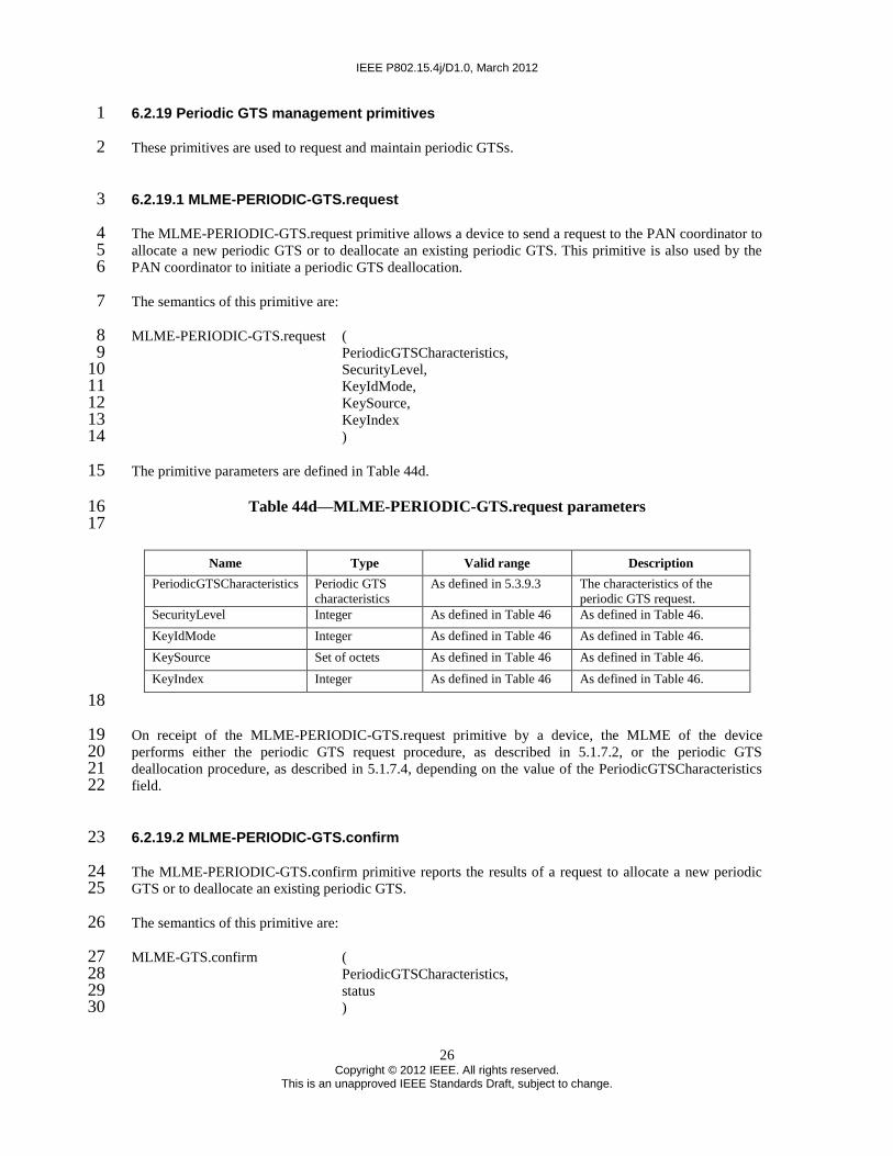
IEEE P802.15.4j/D1.0, March 2012
26 Copyright © 2012 IEEE. All rights reserved.
This is an unapproved IEEE Standards Draft, subject to change.
6.2.19 Periodic GTS management primitives 1
These primitives are used to request and maintain periodic GTSs. 2
6.2.19.1 MLME-PERIODIC-GTS.request 3
The MLME-PERIODIC-GTS.request primitive allows a device to send a request to the PAN coordinator to 4 allocate a new periodic GTS or to deallocate an existing periodic GTS. This primitive is also used by the 5 PAN coordinator to initiate a periodic GTS deallocation. 6
The semantics of this primitive are: 7
MLME-PERIODIC-GTS.request ( 8 PeriodicGTSCharacteristics, 9 SecurityLevel, 10 KeyIdMode, 11 KeySource, 12 KeyIndex 13 ) 14
The primitive parameters are defined in Table 44d. 15
Table 44d—MLME-PERIODIC-GTS.request parameters 16 17
Name Type Valid range Description
PeriodicGTSCharacteristics Periodic GTS
characteristics
As defined in 5.3.9.3 The characteristics of the
periodic GTS request.
SecurityLevel Integer As defined in Table 46 As defined in Table 46.
KeyIdMode Integer As defined in Table 46 As defined in Table 46.
KeySource Set of octets As defined in Table 46 As defined in Table 46.
KeyIndex Integer As defined in Table 46 As defined in Table 46.
18
On receipt of the MLME-PERIODIC-GTS.request primitive by a device, the MLME of the device 19 performs either the periodic GTS request procedure, as described in 5.1.7.2, or the periodic GTS 20 deallocation procedure, as described in 5.1.7.4, depending on the value of the PeriodicGTSCharacteristics 21 field. 22
6.2.19.2 MLME-PERIODIC-GTS.confirm 23
The MLME-PERIODIC-GTS.confirm primitive reports the results of a request to allocate a new periodic 24 GTS or to deallocate an existing periodic GTS. 25
The semantics of this primitive are: 26
MLME-GTS.confirm ( 27 PeriodicGTSCharacteristics, 28 status 29 ) 30

IEEE P802.15.4j/D1.0, March 2012
27 Copyright © 2012 IEEE. All rights reserved.
This is an unapproved IEEE Standards Draft, subject to change.
The primitive parameters are defined in Table 44e. 1
Table 44e—MLME-PERIODIC-GTS.confirm parameters 2 3
Name Type Valid range Description
PeriodicGTSCharacteristics Periodic GTS
characteristics
As defined in 5.3.9.3 The characteristics
of the periodic GTS
request.
status Enumeration SUCCESS,
DENIED,
NO_SHORT_ADDRESS,
CHANNEL_ACCESS_FAILURE,
NO_ACK,
NO_DATA,
COUNTER_ERROR,
FRAME_TOO_LONG,
UNAVAILABLE_KEY,
UNSUPPORTED_SECURITY,
INVALID_PARAMETER.
The status of the
periodic GTS
request.
4
If the request to allocate or deallocate a periodic GTS is successful, this primitive will return a status of 5 SUCCESS and the Characteristics Type field of the PeriodicGTSCharacteristics parameter will have the 6 value of one or zero, respectively. Otherwise, the status parameter will indicate the appropriate error code, 7 as defined in 5.1.7.2 or 5.1.7.4. 8
If macShortAddress is equal to 0xfffe or 0xffff, the device is not permitted to request a periodic GTS and 9 the status parameter will be set to NO_SHORT_ADDRESS. 10
6.2.19.3 MLME-PERIODIC-GTS.indication 11
The MLME-PERIODIC-GTS.indication primitive indicates that a periodic GTS has been allocated or that a 12 previously allocated periodic GTS has been deallocated 13
The semantics of this primitive are: 14
MLME-PERIODIC-GTS.indication ( 15 DeviceAddress, 16 PeriodicGTSCharacteristics, 17 SecurityLevel, 18 KeyIdMode, 19 KeySource, 20 KeyIndex 21 ) 22
The primitive parameters are defined in Table 44f. 23

IEEE P802.15.4j/D1.0, March 2012
28 Copyright © 2012 IEEE. All rights reserved.
This is an unapproved IEEE Standards Draft, subject to change.
Table 44f—MLME-PERIODIC-GTS.indication parameters 1 2
Name Type Valid range Description
DeviceAddress Device
address
0x0000–0xfffd The short address of the device that has
been allocated or deallocated a periodic
GTS.
PeriodicGTSCharacteristics Periodic GTS
characteristics
As defined in 5.3.9.3 The characteristics of the periodic GTS
request.
SecurityLevel Integer As defined in Table 48 If the primitive is generated when a
periodic GTS deallocation is initiated by
the PAN coordinator itself, the security
level to be used is set to 0x00. If the
primitive is generated whenever a
periodic GTS is allocated or deallocated
following the reception of a periodic GTS
request command, then it is as defined in
Table 48.
KeyIdMode Integer As defined in Table 48 If the primitive is generated when a
periodic GTS deallocation is initiated by
the PAN coordinator itself, the security
level to be used is set to 0x00. If the
primitive is generated whenever a
periodic GTS is allocated or deallocated
following the reception of a periodic GTS
request command, then it is as defined in
Table 48.
KeySource Set of octets As defined in Table 48 If the primitive is generated when a
periodic GTS deallocation is initiated by
the PAN coordinator itself, the security
level to be used is set to 0x00. If the
primitive is generated whenever a
periodic GTS is allocated or deallocated
following the reception of a periodic GTS
request command, then it is as defined in
Table 48.
KeyIndex Integer As defined in Table 48 If the primitive is generated when a
periodic GTS deallocation is initiated by
the PAN coordinator itself, the security
level to be used is set to 0x00. If the
primitive is generated whenever a
periodic GTS is allocated or deallocated
following the reception of a periodic GTS
request command, then it is as defined in
Table 48.
3
The value of the Characteristics Type field, as defined in 5.3.9.3, in the PeriodicGTSCharacteristics 4 parameter indicates if the periodic GTS has been allocated or if a periodic GTS has been deallocated. 5
6.2.20 Grant association proxy notification primitives 6
These primitives are used when a device requests a grant of association proxy. 7
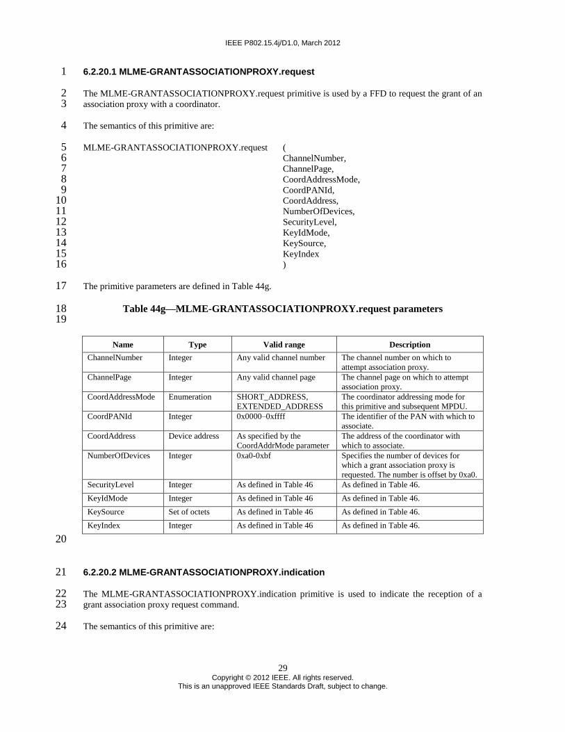
IEEE P802.15.4j/D1.0, March 2012
29 Copyright © 2012 IEEE. All rights reserved.
This is an unapproved IEEE Standards Draft, subject to change.
6.2.20.1 MLME-GRANTASSOCIATIONPROXY.request 1
The MLME-GRANTASSOCIATIONPROXY.request primitive is used by a FFD to request the grant of an 2 association proxy with a coordinator. 3
The semantics of this primitive are: 4
MLME-GRANTASSOCIATIONPROXY.request ( 5 ChannelNumber, 6 ChannelPage, 7 CoordAddressMode, 8 CoordPANId, 9 CoordAddress, 10 NumberOfDevices, 11 SecurityLevel, 12 KeyIdMode, 13 KeySource, 14 KeyIndex 15 ) 16
The primitive parameters are defined in Table 44g. 17
Table 44g—MLME-GRANTASSOCIATIONPROXY.request parameters 18 19
Name Type Valid range Description
ChannelNumber Integer Any valid channel number The channel number on which to
attempt association proxy.
ChannelPage Integer Any valid channel page The channel page on which to attempt
association proxy.
CoordAddressMode Enumeration SHORT_ADDRESS,
EXTENDED_ADDRESS
The coordinator addressing mode for
this primitive and subsequent MPDU.
CoordPANId Integer 0x0000–0xffff The identifier of the PAN with which to
associate.
CoordAddress Device address As specified by the
CoordAddrMode parameter
The address of the coordinator with
which to associate.
NumberOfDevices Integer 0xa0-0xbf Specifies the number of devices for
which a grant association proxy is
requested. The number is offset by 0xa0.
SecurityLevel Integer As defined in Table 46 As defined in Table 46.
KeyIdMode Integer As defined in Table 46 As defined in Table 46.
KeySource Set of octets As defined in Table 46 As defined in Table 46.
KeyIndex Integer As defined in Table 46 As defined in Table 46.
20
6.2.20.2 MLME-GRANTASSOCIATIONPROXY.indication 21
The MLME-GRANTASSOCIATIONPROXY.indication primitive is used to indicate the reception of a 22 grant association proxy request command. 23
The semantics of this primitive are: 24

IEEE P802.15.4j/D1.0, March 2012
30 Copyright © 2012 IEEE. All rights reserved.
This is an unapproved IEEE Standards Draft, subject to change.
MLME-GRANTASSOCIATIONPROXY.indication ( 1 DeviceAddress, 2 NumberOfDevices, 3 SecurityLevel, 4 KeyIdMode, 5 KeySource, 6 KeyIndex 7 ) 8
The primitive parameters are defined in Table 44i 9
Table 44i—MLME-GRANTASSOCIATIONPROXY.indication parameters 10 11
Name Type Valid range Description
DeviceAddress Device address An extended IEEE address The address of the device
requesting a grant of
association proxy.
NumberOfDevices Integer 0xa0-0xbf Specifies the number of
devices for which an
association proxy is
requested. The number of
devices is offset by 0xa0.
SecurityLevel Integer As defined in Table 48 As defined in Table 48.
KeyIdMode Integer As defined in Table 48 As defined in Table 48.
KeySource Set of octets As defined in Table 48 As defined in Table 48.
KeyIndex Integer As defined in Table 48 As defined in Table 48.
12
When the next higher layer of a coordinator receives the MLME-13 GRANTASSOCIATIONPROXY.indication primitive, the coordinator determines whether to accept or 14 reject the unassociated devices using an algorithm outside the scope of this standard. 15
6.2.20.3 MLME-GRANTASSOCIATIONPROXY.response 16
The MLME-GRANTASSOCIATIONPROXY.response primitive reports the results of an MLME-17 GRANTASSOCIATIONPROXY.request primitive. 18
The semantics of this primitive are: 19
MLME-GRANTASSOCIATIONPROXY.response ( 20 DeviceAddress, 21 NumberAllocatedShortAddresses, 22 AssocShortAddress, 23 status, 24 SecurityLevel, 25 KeyIdMode, 26 KeySource, 27 KeyIndex 28 ) 29
The primitive parameters are defined in Table 44j. 30
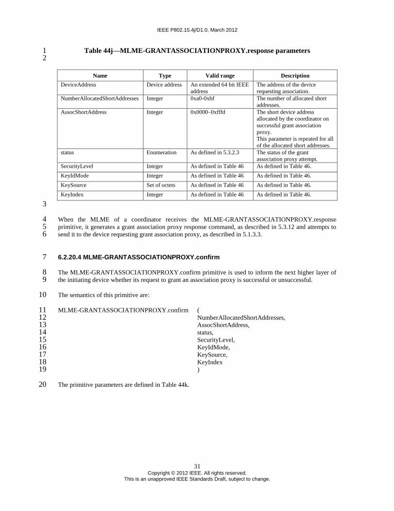
IEEE P802.15.4j/D1.0, March 2012
31 Copyright © 2012 IEEE. All rights reserved.
This is an unapproved IEEE Standards Draft, subject to change.
Table 44j—MLME-GRANTASSOCIATIONPROXY.response parameters 1 2
Name Type Valid range Description
DeviceAddress Device address An extended 64 bit IEEE
address
The address of the device
requesting association.
NumberAllocatedShortAddresses Integer 0xa0-0xbf The number of allocated short
addresses.
AssocShortAddress Integer 0x0000–0xfffd The short device address
allocated by the coordinator on
successful grant association
proxy.
This parameter is repeated for all
of the allocated short addresses.
status Enumeration As defined in 5.3.2.3 The status of the grant
association proxy attempt.
SecurityLevel Integer As defined in Table 46 As defined in Table 46.
KeyIdMode Integer As defined in Table 46 As defined in Table 46.
KeySource Set of octets As defined in Table 46 As defined in Table 46.
KeyIndex Integer As defined in Table 46 As defined in Table 46.
3
When the MLME of a coordinator receives the MLME-GRANTASSOCIATIONPROXY.response 4 primitive, it generates a grant association proxy response command, as described in 5.3.12 and attempts to 5 send it to the device requesting grant association proxy, as described in 5.1.3.3. 6
6.2.20.4 MLME-GRANTASSOCIATIONPROXY.confirm 7
The MLME-GRANTASSOCIATIONPROXY.confirm primitive is used to inform the next higher layer of 8 the initiating device whether its request to grant an association proxy is successful or unsuccessful. 9
The semantics of this primitive are: 10
MLME-GRANTASSOCIATIONPROXY.confirm ( 11 NumberAllocatedShortAddresses, 12 AssocShortAddress, 13 status, 14 SecurityLevel, 15 KeyIdMode, 16 KeySource, 17 KeyIndex 18 ) 19
The primitive parameters are defined in Table 44k. 20

IEEE P802.15.4j/D1.0, March 2012
32 Copyright © 2012 IEEE. All rights reserved.
This is an unapproved IEEE Standards Draft, subject to change.
Table 44k—MLME-GRANTASSOCIATIONPROXY.confirm parameters 1 2
Name Type Valid range Description
NumberAllocatedShortAddresses Integer 0xa0-0xbf The number of allocated
short addresses.
AssocShortAddress Integer 0x0000-0xfffd The short device address
allocated by the
coordinator on
successful grant
association proxy.
This parameter is
repeated for all of the
allocated device short
addresses.
status Enumeration The value of the status field of the
association response command, as
defined in 5.3.2.3,
SUCCESS,
CHANNEL_ACCESS_FAILURE,
NO_ACK,
NO_DATA,
COUNTER_ERROR,
FRAME_TOO_LONG,
IMPROPER_KEY_TYPE,
IMPROPER_SECURITY_LEVEL,
SECURITY_ERROR,
UNAVAILABLE_KEY,
UNSUPPORTED_LEGACY,
UNSUPPORTED_SECURITY,
INVALID_PARAMETER
The status of the
association attempt.
SecurityLevel Integer As defined in Table 48 As defined in Table 48.
KeyIdMode Integer As defined in Table 48 As defined in Table 48.
KeySource Set of octets As defined in Table 48 As defined in Table 48.
KeyIndex Integer As defined in Table 48 As defined in Table 48.
3
If the grant association proxy request is successful, then the status parameter shall be set to SUCCESS. 4 Otherwise, the status parameter shall be set to indicate the type of failure. 5
6.2.21 Grant association proxy notification primitives 6
These primitives are used when a device requests a grant of association proxy. 7
6.2.21.1 MLME-ASSOCIATIONPROXY.request 8
The MLME-ASSOCIATIONPROXY.request primitive is used by a FFD to update the coordinator with the 9 extended address and Capability Information of a device that has been associated using the grant associated 10 proxy command 5.3.11. 11
The semantics of this primitive are: 12

IEEE P802.15.4j/D1.0, March 2012
33 Copyright © 2012 IEEE. All rights reserved.
This is an unapproved IEEE Standards Draft, subject to change.
MLME-ASSOCIATIONPROXY.request ( 1 CoordAddressMode, 2 CoordPANId, 3 CoordAddress, 4 AssocShortAddress, 5 DeviceAddress, 6 CapabilityInformation, 7 SecurityLevel, 8 KeyIdMode, 9 KeySource, 10 KeyIndex 11 ) 12
The primitive parameters are defined in Table 44l. 13
Table 44l—MLME-ASSOCIATIONPROXY.request parameters 14 15
Name Type Valid range Description
CoordAddressMode Enumeration SHORT_ADDRESS,
EXTENDED_ADDRESS
The addressing mode of the coordinator
to which the association proxy is
intended.
CoordPANId Integer 0x0000–0xffff The PAN identifier of the coordinator to
which the association proxy is intended.
CoordAddress Device address As specified by the
CoordAddrMode parameter
The address of the coordinator to which
the association proxy in intended.
AssocShortAddress Integer 0x0000–0xfffd The short device address allocated by
the coordinator on successful
association.
DeviceAddress Device address An extended address The address of the device requesting an
association proxy.
CapabilityInformation Bitmap As defined in 5.3.1.2 The operational capabilities of the
device requesting an association proxy.
SecurityLevel Integer As defined in Table 46 As defined in Table 46.
KeyIdMode Integer As defined in Table 46 As defined in Table 46.
KeySource Set of octets As defined in Table 46 As defined in Table 46.
KeyIndex Integer As defined in Table 46 As defined in Table 46.
16
The AssocShortAddress is the address that is allocated to a device during the grant association proxy 17 request. The DeviceAddress and Capability Information are for this device. 18
6.2.21.2 MLME-ASSOCIATIONPROXY.indication 19
The MLME-ASSOCIATIONPROXY.indication primitive is used to inform the next higher layer of the 20 coordinator of the extended address and Capability Information for a device that is allocated a short address 21 during the grant association proxy request. 22
The semantics of this primitive are: 23

IEEE P802.15.4j/D1.0, March 2012
34 Copyright © 2012 IEEE. All rights reserved.
This is an unapproved IEEE Standards Draft, subject to change.
MLME-ASSOCIATIONPROXY.indication ( 1 CoordAddressMode, 2 CoordPANId, 3 CoordAddress, 4 AssocShortAddress, 5 DeviceAddress, 6 CapabilityInformation, 7 SecurityLevel, 8 KeyIdMode, 9 KeySource, 10 KeyIndex 11 ) 12
The primitive parameters are defined in Table 44m. 13
Table 44m—MLME-ASSOCIATIONPROXY.indication parameters 14 15
Name Type Valid range Description
CoordAddressMode Enumeration SHORT_ADDRESS,
EXTENDED_ADDRESS
The addressing mode of the
coordinator to which the
association proxy is intended.
CoordPANId Integer 0x0000–0xffff The PAN identifier of the
coordinator to which the
association proxy is intended.
CoordAddress Device address As specified by the
CoordAddrMode parameter
The address of the coordinator
to which the association proxy
in intended.
AssocShortAddress Integer 0x0000–0xfffd The short device address
allocated by the coordinator on
successful association.
DeviceAddress Device address An extended address The address of the device
requesting an association proxy.
CapabilityInformation Bitmap As defined in 5.3.1.2 The operational capabilities of
the device requesting an
association proxy.
SecurityLevel Integer As defined in Table 48 As defined in Table 48.
KeyIdMode Integer As defined in Table 48 As defined in Table 48.
KeySource Set of octets As defined in Table 48 As defined in Table 48.
KeyIndex Integer As defined in Table 48 As defined in Table 48.
16
6.2.21.3 MLME-ASSOCIATIONPROXY.confirm 17
The MLME-ASSOCIATIONPROXY.confirm primitive reports the results of an association proxy 18 command to update the coordinator with the associated device-specific information. 19
The semantics of this primitive are: 20
MLME-ASSOCIATIONPROXY.confirm ( 21 AssocShortAddress, 22 DeviceAddress, 23 status 24 ) 25

IEEE P802.15.4j/D1.0, March 2012
35 Copyright © 2012 IEEE. All rights reserved.
This is an unapproved IEEE Standards Draft, subject to change.
The primitive parameters are defined in Table 44n. 1
Table 44n—MLME.ASSOCIATIONPROXY.confirm parameters 2 3
Name Type Valid range Description
AssocShortAddress Integer 0x0000–0xfffd The short device address
allocated by the coordinator
on successful association.
DeviceAddress Device address An extended address The address of the device
requesting an association
proxy.
status Enumeration The value of the status field of the
association response command, as
defined in 5.3.2.3,
SUCCESS,
DENIED,
NO_SHORT_ADDRESS,
CHANNEL_ACCESS_FAILURE,
NO_ACK,
NO_DATA,
COUNTER_ERROR,
FRAME_TOO_LONG,
UNAVAILABLE_KEY,
UNSUPPORTED_SECURITY,
INVALID_PARAMETER
The status of the association
proxy request.
4
If the association proxy request is successful, then the status parameter shall be set to SUCCESS. 5 Otherwise, the status parameter shall be set to indicate the type of failure. 6
6.2.22 Coordinator switch notification primitives 7
These primitives are used when a device requests a coordinator switch. 8
6.2.22.1 MLME-COORDINATOR-SWITCH.request 9
The MLME-COORDINATOR-SWITCH.request primitive is used by a PAN coordinator to request a 10 coordinator switch from other coordinators. 11
The semantics of this primitive are: 12
MLME-COORDINATOR-SWITCH.request ( 13 ChannelNumber, 14 ChannelPage, 15 SrcAddrMode, 16 DstAddrMode, 17 NumberOfDevices, 18 SecurityLevel, 19 KeyIdMode, 20 KeySource, 21 KeyIndex 22 ) 23

IEEE P802.15.4j/D1.0, March 2012
36 Copyright © 2012 IEEE. All rights reserved.
This is an unapproved IEEE Standards Draft, subject to change.
The primitive parameters are defined in Table 44o. 1
Figure 44o–MLME-COORDINATOR-SWITCH.request parameters 2 3
Name Type Valid range Description
ChannelNumber Integer Any valid channel number The channel number on which to
attempt a coordinator switch.
ChannelPage Integer Any valid channel page The channel page on which to
attempt a coordinator switch.
SrcAddrMode Enumeration SHORT_ADDRESS,
EXTENDED_ADDRESS
The source addressing mode for
this MPDU.
DstAddrMode Enumeration SHORT_ADDRESS,
EXTENDED_ADDRESS
The destination addressing mode
for this MPDU.
NumberOfDevices Integer 0x00-0xff Specifies the number of devices
that the coordinator wishes to
switch to another coordinator.
SecurityLevel Integer As defined in Table 46 As defined in Table 46.
KeyIdMode Integer As defined in Table 46 As defined in Table 46.
KeySource Set of octets As defined in Table 46 As defined in Table 46.
KeyIndex Integer As defined in Table 46 As defined in Table 46.
4
On receipt of the MLME-COORDINATOR-SWITCH.request primitive, the MLME of a coordinator shall 5 first update the appropriate PHY and MAC PIB attributes, and then generates a coordinator switch 6 command as defined in 5.3.15. 7
6.2.22.2 MLME-COORDINATOR-SWITCH.indication 8
The MLME-COORDINATOR-SWITCH.indication primitive is used to indicate the reception of a 9 coordinator switch request command. 10
The semantics of this primitive are as follows: 11
MLME-COORDINATOR-SWITCH.indication ( 12 CoordPANId, 13 DeviceAddress, 14 NumberOfDevices, 15 SecurityLevel, 16 KeyIdMode, 17 KeySource, 18 KeyIndex 19 ) 20
The primitive parameters are defined in Table 44p 21

IEEE P802.15.4j/D1.0, March 2012
37 Copyright © 2012 IEEE. All rights reserved.
This is an unapproved IEEE Standards Draft, subject to change.
Table 44p–MLME-COORDINATOR-SWITCH.indication parameters 1 2
Name Type Valid range Description
CoordPANId Integer 0x0000–0xfffe The PAN identifier of the coordinator
requesting a coordinator switch.
DeviceAddress Device address An extended address The address of the coordinator
requesting a coordinator switch
NumberOfDevices Integer 0x00-0xff Specifies the number of devices for
which a coordinator switch is being
requested.
SecurityLevel Integer As defined in Table 48 As defined in Table 48.
KeyIdMode Integer As defined in Table 48 As defined in Table 48.
KeySource Set of octets As defined in Table 48 As defined in Table 48.
KeyIndex Integer As defined in Table 48 As defined in Table 48.
3
When the next higher layer of a coordinator receives the MLME-COORDINATOR-SWITCH.indication 4 primitive, the next higher layer shall determine whether it has the resources to be able to accept the 5 association of additional devices using an algorithm outside the scope of this standard. 6
6.2.22.3 MLME-COORDINATOR-SWITCH.response 7
The MLME-COORDINATOR-SWITCH.response primitive reports the results of an MLME-8 COORDINATOR-SWITCH.request primitive. 9
The semantics of this primitive are as follows: 10
MLME-COORDINATOR-SWITCH.response ( 11 CoordPANId, 12 DeviceAddress, 13 NumberOfDevices, 14 SecurityLevel, 15 KeyIdMode, 16 KeySource, 17 KeyIndex 18 ) 19
The primitive parameters are defined in Table 44q. 20

IEEE P802.15.4j/D1.0, March 2012
38 Copyright © 2012 IEEE. All rights reserved.
This is an unapproved IEEE Standards Draft, subject to change.
Table 44q–MLME-COORDINATOR-SWITCH.response parameters 1 2
Name type Valid range Description
CoordPANId Integer 0x0000–0xfffe The PAN identifier of the
coordinator requesting a
coordinator switch.
DeviceAddress Device address An extended address The address of the coordinator
requesting a coordinator switch.
NumberOfDevices Integer 0x00–0xff Confirms the number of devices
for which a coordinator switch is
being requested.
SecurityLevel Integer As defined in Table 46 As defined in Table 46.
KeyIdMode Integer As defined in Table 46 As defined in Table 46.
KeySource Set of octets As defined in Table 46 As defined in Table 46.
KeyIndex Integer As defined in Table 46 As defined in Table 46.
3
When the MLME of a coordinator receives the MLME-COORDINATOR-SWITCH.response primitive, it 4 shall generate a coordinator response command as described in 5.3.16 in response to a broadcast 5 coordinator switch request and in response to a unicast coordinator switch request command as described in 6 5.1.2.6. 7
6.2.22.4 MLME-COORDINATOR-SWITCH.confirm 8
The MLME-COORDINATOR-SWITCH.confirm primitive is used to inform the next higher layer of the 9 initiating device whether its request for coordinator switch is successful or unsuccessful. 10
The semantics of this primitive are: 11
MLME-COORDINATOR-SWITCH.confirm ( 12 CoordPANId, 13 DeviceAddress, 14 NumberOfDevices, 15 status, 16 SecurityLevel, 17 KeyIdMode, 18 KeySource, 19 KeyIndex 20 ) 21
The primitive parameters are defined in Table 44r. 22

IEEE P802.15.4j/D1.0, March 2012
39 Copyright © 2012 IEEE. All rights reserved.
This is an unapproved IEEE Standards Draft, subject to change.
Table 44r–MLME-COORDINATOR-SWITCH.confirm parameters 1 2
Name Type Valid range Description
CoordPANId Integer 0x0000–0xfffe The PAN identifier of the new
coordinator.
DeviceAddress Device address An extended address The address of the new
coordinator.
NumberOfDevices Integer 0x00–0xff Confirms the number of
devices for which a
coordinator switch is being
requested.
If this value is 0x00 then the
coordinator switch request was
unsuccessful.
status Enumeration SUCCESS,
CHANNEL_ACCESS_FAILURE,
NO_ACK,
NO_DATA,
COUNTER_ERROR,
FRAME_TOO_LONG,
IMPROPER_KEY_TYPE,
IMPROPER_SECURITY_LEVEL,
SECURITY_ERROR,
UNAVAILABLE_KEY,
UNSUPPORTED_LEGACY,
UNSUPPORTED_SECURITY,
INVALID_PARAMETER
The status of the association
attempt.
SecurityLevel Integer As defined in Table 48 As defined in Table 48.
KeyIdMode Integer As defined in Table 48 As defined in Table 48.
KeySource Set of octets As defined in Table 48 As defined in Table 48.
KeyIndex Integer As defined in Table 48 As defined in Table 48.
3
If the coordinator switch request is successful, then the status parameter will be set to SUCCESS. 4 Otherwise, the status parameter will be set to indicate the type of failure. 5
6.3 MAC data service 6
6.4 MAC constants and PIB attributes 7
6.4.1 MAC constants 8
6.4.2 MAC PIB attributes 9
Insert as shown in Table 52: 10

IEEE P802.15.4j/D1.0, March 2012
40 Copyright © 2012 IEEE. All rights reserved.
This is an unapproved IEEE Standards Draft, subject to change.
Table 52–MAC PIB attributes 1 2
Attribute Type Range Description Default
macPeriodicGTSPermit* Boolean TRUE, FALSE TRUE if the PAN coordinator is to accept
Periodic GTS requests. FALSE otherwise. TRUE
3
7. Security 4
8. General PHY requirements 5
8.1 General requirements and definitions 6
Iinsert in 8.1: 7
O-QPSK PHY: direct sequence spread spectrum (DSSS) PHY employing offset quadrature 8 phase¬shift keying (O-QPSK) modulation, operating in the 780 MHz bands, 868 MHz, 915 MHz, 9 2380 MHz, and 2450 MHz, as defined in clause 10. 10
8.1.1 Operating frequency range 11
Insert as shown in table 66: 12
Table 66–Frequency bands and data rates 13 14
PHY
(MHz)
Frequency
band
(MHz)
Spreading parameters Data parameters
Chip rate
(kchip/s) Modulation
Bit rate
(kb/s)
Symbol rate
(ksymbol/s) Symbols
2380 DSSS 2360-2400 2000 O-QPSK 250 62.5 16-ary
Orthogonal
15
8.1.2 Channel assignments 16
8.1.2.1 Channel numbering for 780 MHz band 17
8.1.2.2 Channel numbering for 868 MHz, 915 MHz, and 2450 MHz bands 18
8.1.2.3 Channel numbering for 950 MHz band 19
8.1.2.4 Channel numbering for CSS PHY 20

IEEE P802.15.4j/D1.0, March 2012
41 Copyright © 2012 IEEE. All rights reserved.
This is an unapproved IEEE Standards Draft, subject to change.
8.1.2.5 Channel numbering for UWB PHY 1
Insert after 8.1.2.5: 2
8.1.2.6 Channel numbering for 2380 MHz band 3
For channel page 7, 15 channels numbered zero to fourteen are available across the 2380 MHz band. The 4 center frequencies of these channels are defined as follows: 5
Fc = 2363 + 5 k in MHz, for k = 0, 1, …, 6 6
Fc = 2367 + 5 (k – 7) in MHz, for k = 7, 8, …, 13 7
and Fc = 2395 in MHz, for k = 14 8
where 9
k is the channel number. 10
9. PHY services 11
10. O-QPSK PHY 12
10.1 PPDU format 13
10.2 Modulation and spreading 14
10.2.1 Data rate 15
Change and insert in the first paragraph of 10.2.1: 16
The data rate of the O-QPSK PHY shall be 250 kb/s when operating in the 2450 MHz, 915 MHz, or 780 17 MHz, or 2380 MHz bands and shall be 100 kb/s when operating in the 868 MHz band. 18
10.2.2 Reference modulator diagram 19
10.2.3 Bit-to-symbol mapping 20
10.2.4 Symbol-to-chip mapping 21
Insert in the first paragraph of 10.2.4: 22

IEEE P802.15.4j/D1.0, March 2012
42 Copyright © 2012 IEEE. All rights reserved.
This is an unapproved IEEE Standards Draft, subject to change.
In the 2450 MHz and 2380 MHz bands, each data symbol shall be mapped into a 32-chip PN sequence as 1 specified in Table 73. The PN sequences are related to each other through cyclic shifts and/or conjugation 2 (i.e., inversion of odd-indexed chip values). 3
Insert in the title of Table 73: 4
Table 73—Symbol-to-chip mapping for the 2450 MHz and 2380 MHz bands 5 6
10.2.5 O-QPSK modulation 7
Insert in the first paragraph of 10.2.5: 8
The chip sequences representing each data symbol are modulated onto the carrier using O-QPSK with half-9 sine pulse shaping. Even-indexed chips are modulated onto the in-phase (I) carrier, and odd-indexed chips 10 are modulated onto the quadrature-phase (Q) carrier. In the 2450 MHz and 2380 MHz bands, each data 11 symbol is represented by a 32-chip sequence, and so the chip rate is 32 times the symbol rate. In the 915 12 MHz, 868 MHz, and 780 MHz bands, each data symbol is represented by a 16-chip sequence, and so the 13 chip rate is 16 times the symbol rate. To form the offset between I-phase and Q-phase chip modulation, the 14 Q-phase chips shall be delayed by Tc with respect to the I-phase chips, as illustrated in Figure 70, where Tc 15 is the inverse of the chip rate. 16
10.2.6 Pulse shape 17
Change and insert in the first paragraph of 10.2.6: 18
In the 2450 MHz, 915 MHz, and 868 MHz, and 2380 MHz bands, the half-sine pulse shape is used to 19 represent each baseband chip and is given by: 20
10.2.7 Chip transmission order 21
Insert in 10.2.7: 22
During each symbol period, the least significant chip, c0, is transmitted first and the most significant chip, 23 either c31, for the 2450 MHz and 2380 MHz bands, or c15, for the 915 MHz, 868 MHz, and 780 MHz bands, 24 is transmitted last. 25
10.3 O-QPSK PHY RF requirements 26
10.3.1 Operating frequency range 27
Insert as shown in 10.3.1: 28
— 779–787 MHz 29 — 868.0–868.6 MHz 30 — 902–928 MHz 31 — 2360–2400 MHz 32 — 2400.0–2483.5 MHz 33
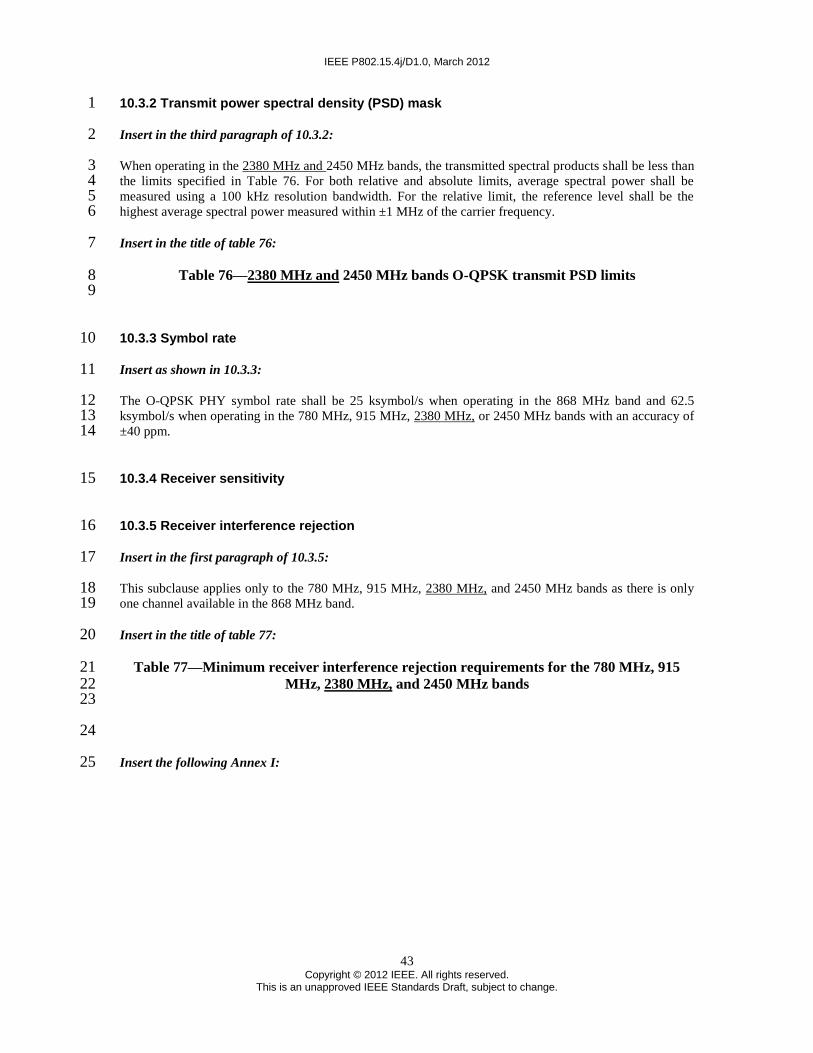
IEEE P802.15.4j/D1.0, March 2012
43 Copyright © 2012 IEEE. All rights reserved.
This is an unapproved IEEE Standards Draft, subject to change.
10.3.2 Transmit power spectral density (PSD) mask 1
Insert in the third paragraph of 10.3.2: 2
When operating in the 2380 MHz and 2450 MHz bands, the transmitted spectral products shall be less than 3 the limits specified in Table 76. For both relative and absolute limits, average spectral power shall be 4 measured using a 100 kHz resolution bandwidth. For the relative limit, the reference level shall be the 5 highest average spectral power measured within ±1 MHz of the carrier frequency. 6
Insert in the title of table 76: 7
Table 76—2380 MHz and 2450 MHz bands O-QPSK transmit PSD limits 8 9
10.3.3 Symbol rate 10
Insert as shown in 10.3.3: 11
The O-QPSK PHY symbol rate shall be 25 ksymbol/s when operating in the 868 MHz band and 62.5 12 ksymbol/s when operating in the 780 MHz, 915 MHz, 2380 MHz, or 2450 MHz bands with an accuracy of 13 ±40 ppm. 14
10.3.4 Receiver sensitivity 15
10.3.5 Receiver interference rejection 16
Insert in the first paragraph of 10.3.5: 17
This subclause applies only to the 780 MHz, 915 MHz, 2380 MHz, and 2450 MHz bands as there is only 18 one channel available in the 868 MHz band. 19
Insert in the title of table 77: 20
Table 77—Minimum receiver interference rejection requirements for the 780 MHz, 915 21 MHz, 2380 MHz, and 2450 MHz bands 22
23
24
Insert the following Annex I: 25

IEEE P802.15.4j/D1.0, March 2012
44 Copyright © 2012 IEEE. All rights reserved.
This is an unapproved IEEE Standards Draft, subject to change.
Annex I 1
(informative) 2
Channel bitmap 3
I.1 General 4
To assist with coexistence to the primary users of the 2360-2400 MHz band, some parts of this band may 5 be excluded from use by MBANS devices. Those parts of the band that are excluded from use may change 6 from time to time. Regulation requires that the operation of MBANS hub
2 devices have access to a 7
mechanism that provides information on which parts of the band cannot be used. The description of this 8 mechanism is beyond the scope of this annex. To assist other MBANS devices such as sensors that do not 9 have direct access to this mechanism, a bitmap may be used by a hub device to indicate those channels that 10 are allowed to be used by MBANS devices. The bitmap only applies to those channels that are in the 2360-11 2390 MHz band (channels 0-5 and 7-12). The channels in the 2390-2400 MHz band (channels 6, 13 and 12 14) are always available for use. 13
I.2 Channel bitmap 14
A bitmap of those channels that are available for use may be inserted into the beacon payload. The bitmap 15 shall be formatted as shown in Table I.1. 16
Table I.1–Channel bitmap 17 18
Bits: 0-11 Bit 12-22 Bit 23
Channel bitmap Valid time Reserved
19
The bit-to-channel numbering of the channel bitmap field is shown in Table I.2. The channel numbering is 20 described in 8.1.2.6. 21
2 MBANS hub devices are 802.15.4 PAN coordinators.

IEEE P802.15.4j/D1.0, March 2012
45 Copyright © 2012 IEEE. All rights reserved.
This is an unapproved IEEE Standards Draft, subject to change.
Table I.2–Bit-to-channel numbering 1 2
Bit Channel, k
0 0
1 1
2 2
3 3
4 4
5 5
6 7
7 8
8 9
9 10
10 11
3
The bits of the channel bitmap field shall be set to one when the corresponding channels are available for 4 use and the bits of the channel bitmap field shall be set to zero when the corresponding channels are not 5 available for use. 6
The Valid time field indicates the duration in minutes of the availability of the channel bitmap. 7
8