ied-1000 - download.level1.comdownload.level1.com/level1/manual/ied-1000-v1_um_v1.0.pdf · xport...
TRANSCRIPT

IED-1000
User Manual
v1.00 - 1210

INTRODUCTION .................................................................................................................................. 4
FEATURES ................................................................................................................................................ 4
PACKAGE CONTENTS .......................................................................................................................... 5
LED STATUS ............................................................................................................................................. 5
POWER INPUT .................................................................................................................................... 6
INSTALLATION .................................................................................................................................... 7
IP CONFIGURATION ................................................................................................................................... 7 DEFAULT IP SETTINGS ................................................................................................................................ 7
Configure IP by Utility ..................................................................................................................... 8 Configure IP by web interface ......................................................................................................... 8 Configure IP by Telnet utility ........................................................................................................... 8
TCP/IP PORT NUMBER.............................................................................................................................. 9
WEB CONFIGURATION ..................................................................................................................... 10
OVERVIEW ............................................................................................................................................ 11 BASIC NETWORK SETTINGS ....................................................................................................................... 12 SERIAL PORT SETTINGS ............................................................................................................................ 13
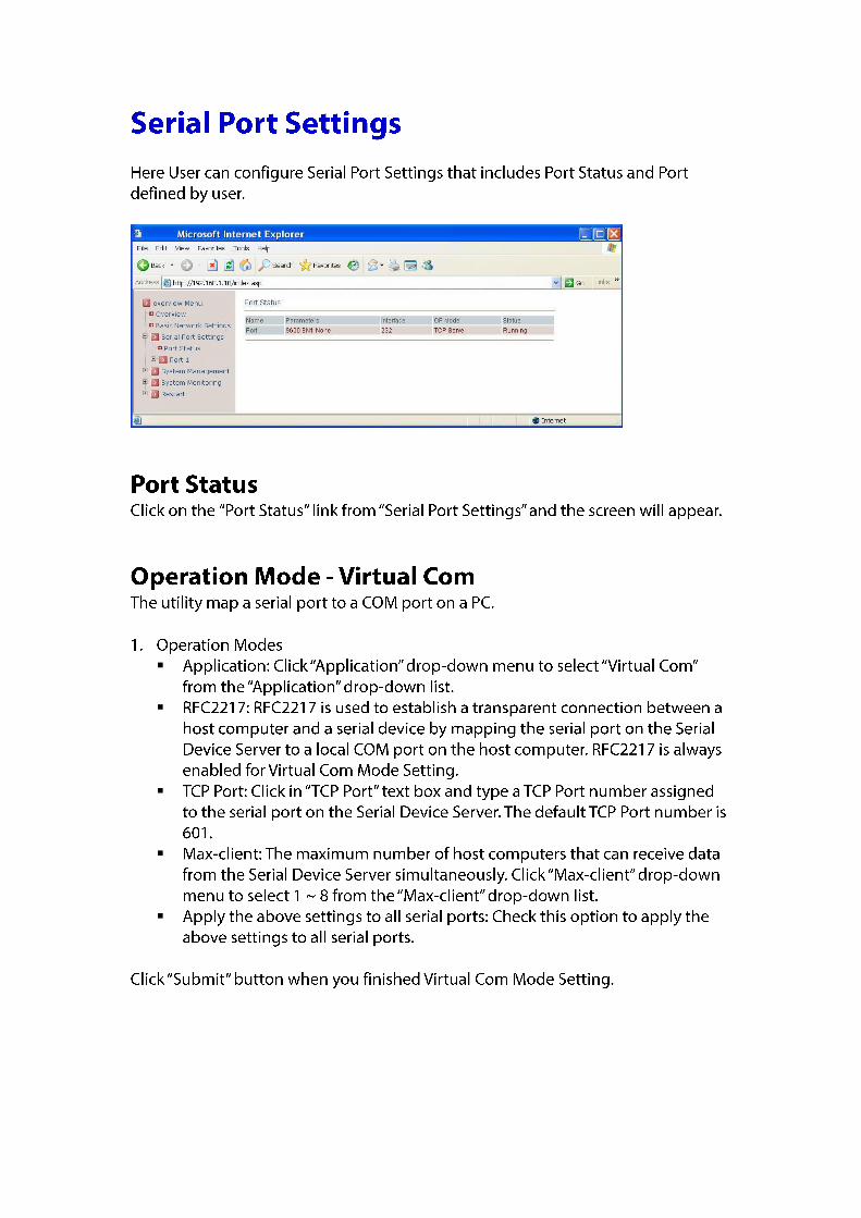
Port Status ..................................................................................................................................... 13 Operation Mode - Virtual Com ...................................................................................................... 13 Operation Mode - Pair Connection................................................................................................ 16 Operation Mode - TCP Server ........................................................................................................ 18 Operation Mode - TCP Client ......................................................................................................... 20 Operation Mode - UDP .................................................................................................................. 22
SYSTEM MANAGEMENT ........................................................................................................................... 25 Server Name .................................................................................................................................. 25 Change Password .......................................................................................................................... 26 E-mail Alert ................................................................................................................................... 26 SNMP Trap .................................................................................................................................... 27 Restore Factory Default ................................................................................................................. 27 Firmware Update .......................................................................................................................... 28
SYSTEM MONITORING ............................................................................................................................. 29 Serial to Network Connections ...................................................................................................... 29 System Log .................................................................................................................................... 29 Event Log ....................................................................................................................................... 30
RESTART ................................................................................................................................................ 31 Restart Port ................................................................................................................................... 31 Restart System ............................................................................................................................... 31
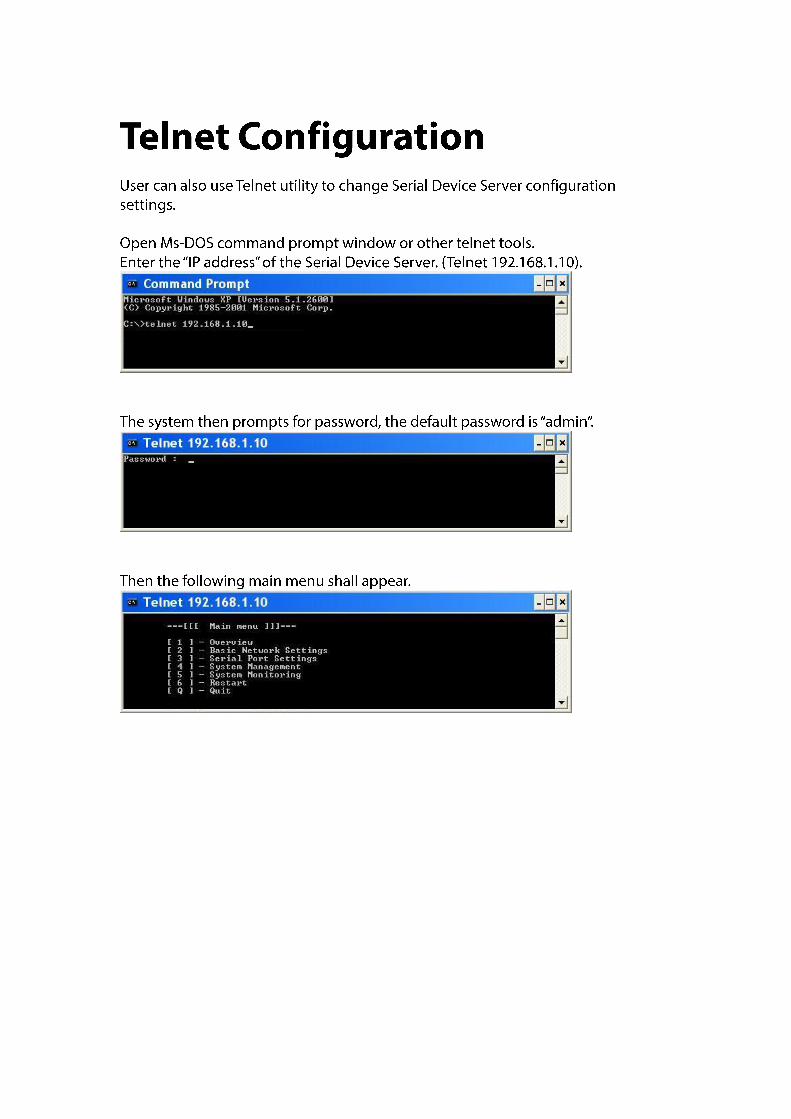
TELNET CONFIGURATION ................................................................................................................. 32
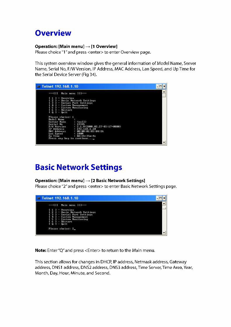
OVERVIEW ............................................................................................................................................ 33 BASIC NETWORK SETTINGS ....................................................................................................................... 33 SERIAL PORT SETTINGS ............................................................................................................................ 34
Port Status ..................................................................................................................................... 34 Operation Modes .......................................................................................................................... 35 Communication Parameters.......................................................................................................... 37 Accessible IP List ............................................................................................................................ 37
SYSTEM MANAGEMENT ........................................................................................................................... 38 Server Name Setting ..................................................................................................................... 38 Change Password .......................................................................................................................... 38 E-mail Alert ................................................................................................................................... 38

SNMP Trap .................................................................................................................................... 39 Restore Factory Default ................................................................................................................. 39
SYSTEM MONITORING ............................................................................................................................. 40 Serial to Network Connections ...................................................................................................... 40 System Log .................................................................................................................................... 41 Event Log ....................................................................................................................................... 41
RESTART ................................................................................................................................................ 42 Restart Port ................................................................................................................................... 42 Restart System ............................................................................................................................... 42
REFERENCE....................................................................................................................................... 43
XPORT UTILITY ....................................................................................................................................... 43 1.1. XPORT UTILITY INTRODUCTION .................................................................................................... 43 1.2. INTERFACE ............................................................................................................................... 43 1.3. DEVICE LIST ............................................................................................................................. 43
1.3.1. Login to System by Web Interface ................................................................................... 43 1.3.2. Functions ......................................................................................................................... 44 1.3.3. Serial port ....................................................................................................................... 44 1.3.4. COM List .......................................................................................................................... 47
1.4. FILE ....................................................................................................................................... 49 1.4.1. Logon .............................................................................................................................. 49 1.4.2. Logoff .............................................................................................................................. 49 1.4.3. Load utility setting .......................................................................................................... 49 1.4.4. Save utility setting .......................................................................................................... 50 1.4.5. Exit .................................................................................................................................. 50
1.5. TOOLS .................................................................................................................................... 50 1.5.1. Auto-search ..................................................................................................................... 51 1.5.2. Manual-search ................................................................................................................ 51 1.5.3. Locate ............................................................................................................................. 51
1.6. SETTING ................................................................................................................................. 51 1.6.1. Serial Port Settings .......................................................................................................... 52 1.6.2. Basic Network Settings ................................................................................................... 62 1.6.3. System Management ...................................................................................................... 63 1.6.4. Utility Setting .................................................................................................................. 64
1.7. MONITORING .......................................................................................................................... 65 1.7.1. Port Status ...................................................................................................................... 65 1.7.2. Logs ................................................................................................................................. 66
1.8. RESTART ................................................................................................................................. 66 1.8.1. Restart Port ..................................................................................................................... 67 1.8.2. Restart System ................................................................................................................ 67 1.8.3. Restart All Ports .............................................................................................................. 67
1.9. COM ..................................................................................................................................... 67 1.9.1. Create a new COM port .................................................................................................. 68 1.9.2. Remove all COM ports .................................................................................................... 69
1.10. HELP ...................................................................................................................................... 69 SPECIFICATIONS ...................................................................................................................................... 71 PIN ASSIGNMENTS .................................................................................................................................. 72
Serial port - DDB-9: ....................................................................................................................... 72 Terminal Block: .............................................................................................................................. 72
o
o
o


→
→


→
→

→ →

→ →
→ → →
→ → →

→ → →
→ → →
→ → →

→ →
→ →

→ →
→ →
→ →

→ →
→ →

User can configure System Monitoring that includes Serial to Network Connections, System Log, and Event Log.
→ →

→ →
→ →

→ →
→ →

Xport Utility is a tool for device management and configuration, and can realize the daily management on various network devices for address search, device positioning, parameter configuring, firmware downloading and so on.
The operating interface of the Xport utility shown as below:
Fig 50. The operating interface of the Xport utility
User can double click on the IP address of the Serial Device Server to login to Serial Device Server by web interface.

Fig 50. Login to System by Web Interface
User can click right button of mouse on the IP address of the Serial Device Server to show functions as Fig 51.
Fig 51. Functions
User can click right button of mouse on the serial port of the Serial Device Server to show as Fig 52.
Fig 52. Serial port

Auto-mapping a COM port User can use the Xport utility to automatically map a serial port to a COM port on a PC. The serial port on the Serial Device Server has to be set to Virtual Com mode when mapping COM port with Xport utility.
1. Map successfully: The serial port on the Serial Device Server has been successfully mapped to a COM port on a PC.
Fig 53. Auto-mapping a COM port 2. COM List: Click right button of mouse on the COM port to show as Fig 54.
Fig 54. COM List 3. Modify Setting: User can modify Network setting and Serial setting of COM port settings as
Fig 55. and Fig 56. Network setting: Remote IP address: Input the IP address of the remote Serial Device Server. TCP port: Choose TCP port number assigned to the COM port. The default TCP port number is 601. Active auto-reconnect: Check this option to support Active auto-reconnect. The Xport utility will automatically attempt to reconnect COM port to the serial port on the Serial Device Server. Reconnect interval: The Xport utility will automatically attempt to reconnect COM port to the serial port on the Serial Device Server in defined time interval (Reconnect interval). The default Reconnect interval is 1000ms. Cache data when connection was broken: Check this option to ensure that data is buffered if the connection is broken.

Fig 55. Network setting Serial setting: Serial port protocol: Choose Raw protocol or RFC2217 protocol. Serial port preset signals: There are CTS, DSR, DCD, and RING serial port preset signals that can be chosen. Enable bitrate emulation: Check this option to limit data transmission speed to that was specified to serial port. Transmission speed depends on bandwidth of the serial connection if bitrate emulation is disabled.
Fig 56. Serial setting 4. Remove COM port: Remove the COM port and remove mapping the serial port to a COM
port on a PC.
Fig 57. Serial setting Manual-mapping a COM port User can use the Xport utility to manually map a serial port to a COM port on a PC. The serial port on the Serial Device Server has to be set to Virtual Com mode when mapping COM port with Xport utility. 1. Network setting: TCP port: Choose TCP port number assigned to the COM port. The default TCP port
number is 601. Active auto-reconnect: Check this option to support Active auto-reconnect. The Xport
utility will automatically attempt to reconnect COM port to the serial port on the Serial Device Server.
Reconnect interval: The Xport utility will automatically attempt to reconnect COM port to

the serial port on the Serial Device Server in defined time interval (Reconnect interval). The default Reconnect interval is 1000ms.
Cache data when connection was broken: Check this option to ensure that data is buffered if the connection is broken.
Fig 58. Network setting 2. Serial setting: Serial port protocol: Choose Raw protocol or RFC2217 protocol. Serial port preset signals: There are CTS, DSR, DCD, and RING serial port preset signals
that can be chosen. Enable bitrate emulation: Check this option to limit data transmission speed to that was
specified to serial port. Transmission speed depends on bandwidth of the serial connection if bitrate emulation is disabled.
Fig 59. Serial setting Restart port Click “Restart port” to restart serial port on the Serial Device Server.
Click right button of mouse on the COM List to show as Fig 54.
Fig 60. COM List

Create a new COM port User can use the Xport utility to map a serial port to a COM port on a PC. The serial port on the Serial Device Server has to be set to Virtual Com mode when mapping COM port with Xport utility. 1. Network setting: TCP port: Choose TCP port number assigned to the COM port. The default TCP port
number is 601. Active auto-reconnect: Check this option to support Active auto-reconnect. The Xport
utility will automatically attempt to reconnect COM port to the serial port on the Serial Device Server.
Reconnect interval: The Xport utility will automatically attempt to reconnect COM port to the serial port on the Serial Device Server in defined time interval (Reconnect interval). The default Reconnect interval is 1000ms.
Cache data when connection was broken: Check this option to ensure that data is buffered if the connection is broken.
Fig 61. Network setting 2. Serial setting: Serial port protocol: Choose Raw protocol or RFC2217 protocol. Serial port preset signals: There are CTS, DSR, DCD, and RING serial port preset signals
that can be chosen. Enable bitrate emulation: Check this option to limit data transmission speed to that was
specified to serial port. Transmission speed depends on bandwidth of the serial connection if bitrate emulation is disabled.
Fig 62. Serial setting Remove all COM ports Click “Remove all COM ports” to remove all the COM ports and remove all the mapping from the serial ports to COM ports on a PC.

Fig 63. Remove all COM ports
Click “File” from menu bar to show as Fig 64.
Fig 64. File
Click “Logon” from “File” to show the authentication screen as Fig 64. Enter password then click on “OK” button to logon to the Serial Device Server. The default password is “admin”.
Fig 64. Logon
Click “Logoff” from “File” to logoff from the Serial Device Server.
Click “Load utility setting” from “File” to load utility setting file to the Serial Device Server.

Fig 65. Load utility setting
Click “Save utility setting” from “File” to save utility setting file from the Serial Device Server.
Fig 66. Save utility setting
Click “Exit” from “File” to exit from Xport utility.
Click “Tools” from menu bar to show as Fig 67.

Fig 67. Tools
Click “Auto-search” from “Tools” to search all Serial Device Servers connected to the same LAN as your host PC.
Click “Manual-search” from “Tools” to search all Serial Device Servers in a range of IP addresses.
Fig 68. Manual-search
The user can apply this function to locate a Serial Device Server. The flash LED of the Serial Device Server will light on if the Serial Device Server is located.
Click “Setting” from menu bar to show as Fig 69.

Fig 69. Setting
Click “Serial Port Settings” from “Setting” to configure the serial port of the Serial Device Server.
Fig 70. Serial Port Settings File Click “File” from menu bar to show as Fig 71.

Fig 71. File 1. Import Configuration Click “Import Configuration” from “File” to import configuration file to the Serial Device Server.
Fig 72. Import Configuration 2. Export Configuration Click “Export Configuration” from “File” to export configuration file from the Serial Device Server.

Fig 73. Export Configuration 3. Close Click “Close” from “File” to exit from “Serial Port Settings” to the Serial Device Server.
Fig 74. Close Action Click “Action” from menu bar to show as Fig 75.
Fig 75. Action 1. Restart Port Click “Restart Port” from “Action” to restart the serial port on the Serial Device Server. 2. Update ports setting Click “Update ports setting” from “Action” to update the settings of serial port on the Serial

Device Server. Port 1. Virtual COM Step 1: Xport mode Choose “Virtual Com” from the “Step 1: Xport mode”.
Fig 76. Virtual COM Step 2: Serial port settings Baud rate: Click “Baud rate” drop-down menu to select Baud rate 50 ~ 460800bps from the “Baud rate” drop-down list for the serial port. The default Baud rate of the serial port is 9600bps. Data bits: Click “Data bits” drop-down menu to select Data bits 5, 6, 7, or 8 from the “Data bits” drop-down list for the serial port. The default Data bits of the serial port is 8 bits. Stop bits: Click “Stop bits” drop-down menu to select Stop bits 1 or 2 from the “Stop bits” drop-down list for the serial port. The default Stop bits of the serial port is 1 bit. Parity: Click “Parity” drop-down menu to select Parity None, Even, Odd, Mark, or Space from the “Parity” drop-down list for the serial port. The default Parity of the serial port is None. Flow control: Click “Flow control” drop-down menu to select Flow control None, Hardware, or Software from the “Flow control” drop-down list for the serial port. The default Flow control of the serial port is None. Mode: Click “Mode” drop-down menu to select Mode RS232, RS422, or RS485 from the “Mode” drop-down list for the serial port. The default Mode of the serial port is RS232. Step 3: Protocol timeout setting Support protocol timeout auto-detect: Check this option to support protocol timeout auto-detect. The Serial Device Server will automatically test the TCP connection to remote host. If the TCP connection is idle, the TCP connection will be closed and the port will be freed for other hosts. Protocol timeout: Click in “Protocol timeout” text box and type a period of Protocol timeout

assigned to the serial port on the Serial Device Server. The connection will be closed and the port will be freed for connection with other hosts when serial port stops data transmission for a defined period of time (Protocol timeout). The default Protocol timeout is 0ms. Step 4: Data Packing Delimiter1, 2: Check this option to enable Delimiter1, 2. Click in “Delimiter1, 2” text box and Delimiter1, 2 assigned to the serial port on the Serial Device Server. The data will be transmitted if the Delimiter1 is received or Delimiter1 and Delimiter2 are received. Force transmit: Click in “Force transmit” text box and specify Force transmit to the serial port on the Serial Device Server. The data will be transmitted when the Force transmit is reached. The default Force transmit of the serial port is 0 to disable Force transmit. Step 5: Virtual COM Port Network settings Enable the accessible IP list: Check this option to enable the accessible IP list. Disable will allow all IP’s connection request. Accept IP 1 ~ 8: Click in “Accept IP 1 ~ 8” text box and specify Accept IP addresses that can access to the serial port on the Serial Device Server. Check this option to enable the Accept IP addresses. TCP Port: Click in “TCP Port” text box and type a TCP Port number assigned to the serial port on the Serial Device Server. The default TCP Port number is 601. Max client: The maximum number of host computers that can receive data from the Serial Device Server simultaneously. Click “Max client” drop-down menu to select 1 ~ 8 from the “Max client” drop-down list. RFC2217: RFC2217 is used to establish a transparent connection between a host computer and a serial device by mapping the serial port on the Serial Device Server to a local COM port on the host computer. RFC2217 is always enabled for Virtual Com Mode Setting. Restart Port: Check this option to restart the serial port on the Serial Device Server when you click the “OK” button to finish Virtual Com Mode Setting. Apply the above settings to all serial ports: Click this button to apply the above settings to all serial ports. 2. TCP Server Step 1: Xport mode Choose “TCP Server” from the “Step 1: Xport mode”.

Fig 77. TCP Server Step 2: Serial port settings Baud rate: Click “Baud rate” drop-down menu to select Baud rate 50 ~ 460800bps from the “Baud rate” drop-down list for the serial port. The default Baud rate of the serial port is 9600bps. Data bits: Click “Data bits” drop-down menu to select Data bits 5, 6, 7, or 8 from the “Data bits” drop-down list for the serial port. The default Data bits of the serial port is 8 bits. Stop bits: Click “Stop bits” drop-down menu to select Stop bits 1 or 2 from the “Stop bits” drop-down list for the serial port. The default Stop bits of the serial port is 1 bit. Parity: Click “Parity” drop-down menu to select Parity None, Even, Odd, Mark, or Space from the “Parity” drop-down list for the serial port. The default Parity of the serial port is None. Flow control: Click “Flow control” drop-down menu to select Flow control None, Hardware, or Software from the “Flow control” drop-down list for the serial port. The default Flow control of the serial port is None. Mode: Click “Mode” drop-down menu to select Mode RS232, RS422, or RS485 from the “Mode” drop-down list for the serial port. The default Mode of the serial port is RS232. Step 3: Protocol timeout setting Support protocol timeout auto-detect: Check this option to support protocol timeout auto-detect. The Serial Device Server will automatically test the TCP connection to remote host. If the TCP connection is idle, the TCP connection will be closed and the port will be freed for other hosts. Protocol timeout: Click in “Protocol timeout” text box and type a period of Protocol timeout assigned to the serial port on the Serial Device Server. The connection will be closed and the port will be freed for connection with other hosts when serial port stops data transmission for a defined period of time (Protocol timeout). The default Protocol timeout is 0ms. Step 4: Data Packing Delimiter1, 2: Check this option to enable Delimiter1, 2. Click in “Delimiter1, 2” text box and Delimiter1, 2 assigned to the serial port on the Serial Device Server. The data will be

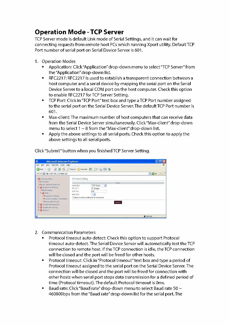
transmitted if the Delimiter1 is received or Delimiter1 and Delimiter2 are received. Force transmit: Click in “Force transmit” text box and specify Force transmit to the serial port on the Serial Device Server. The data will be transmitted when the Force transmit is reached. The default Force transmit of the serial port is 0 to disable Force transmit. Step 5: Server Network settings Enable the accessible IP list: Check this option to enable the accessible IP list. Disable will allow all IP’s connection request. Accept IP 1 ~ 8: Click in “Accept IP 1 ~ 8” text box and specify Accept IP addresses that can access to the serial port on the Serial Device Server. Check this option to enable the Accept IP addresses. TCP Port: Click in “TCP Port” text box and type a TCP Port number assigned to the serial port on the Serial Device Server. The default TCP Port number is 601. Max client: The maximum number of host computers that can receive data from the Serial Device Server simultaneously. Click “Max client” drop-down menu to select 1 ~ 8 from the “Max client” drop-down list. RFC2217: RFC2217 is used to establish a transparent connection between a host computer and a serial device by mapping the serial port on the Serial Device Server to a local COM port on the host computer. Check this option to enable RFC2217 for TCP Server Setting. Restart Port: Check this option to restart the serial port on the Serial Device Server when you click the “OK” button to finish TCP Server Setting. Apply the above settings to all serial ports: Click this button to apply the above settings to all serial ports. 3. TCP Client Step 1: Xport mode Choose “TCP Client” from the “Step 1: Xport mode”.
Fig 78. TCP Client

Step 2: Serial port settings Baud rate: Click “Baud rate” drop-down menu to select Baud rate 50 ~ 460800bps from the “Baud rate” drop-down list for the serial port. The default Baud rate of the serial port is 9600bps. Data bits: Click “Data bits” drop-down menu to select Data bits 5, 6, 7, or 8 from the “Data bits” drop-down list for the serial port. The default Data bits of the serial port is 8 bits. Stop bits: Click “Stop bits” drop-down menu to select Stop bits 1 or 2 from the “Stop bits” drop-down list for the serial port. The default Stop bits of the serial port is 1 bit. Parity: Click “Parity” drop-down menu to select Parity None, Even, Odd, Mark, or Space from the “Parity” drop-down list for the serial port. The default Parity of the serial port is None. Flow control: Click “Flow control” drop-down menu to select Flow control None, Hardware, or Software from the “Flow control” drop-down list for the serial port. The default Flow control of the serial port is None. Mode: Click “Mode” drop-down menu to select Mode RS232, RS422, or RS485 from the “Mode” drop-down list for the serial port. The default Mode of the serial port is RS232. Step 3: Protocol timeout setting Support protocol timeout auto-detect: Check this option to support protocol timeout auto-detect. The Serial Device Server will automatically test the TCP connection to remote host. If the TCP connection is idle, the TCP connection will be closed and the port will be freed for other hosts. Protocol timeout: Click in “Protocol timeout” text box and type a period of Protocol timeout assigned to the serial port on the Serial Device Server. The connection will be closed and the port will be freed for connection with other hosts when serial port stops data transmission for a defined period of time (Protocol timeout). The default Protocol timeout is 0ms. Step 4: Data Packing Delimiter1, 2: Check this option to enable Delimiter1, 2. Click in “Delimiter1, 2” text box and Delimiter1, 2 assigned to the serial port on the Serial Device Server. The data will be transmitted if the Delimiter1 is received or Delimiter1 and Delimiter2 are received. Force transmit: Click in “Force transmit” text box and specify Force transmit to the serial port on the Serial Device Server. The data will be transmitted when the Force transmit is reached. The default Force transmit of the serial port is 0 to disable Force transmit. Step 5: Client Network settings Remote IP 1 ~ 8: Click in “Remote IP 1 ~ 8” text boxes to specify IP addresses and Port numbers of remote host computers. Connect timeout: Click in “Connect timeout” text box and type a period of Connect timeout assigned to the serial port on the Serial Device Server. The connection will be closed and the port will be freed for connection with other hosts when serial port stops data transmission for a defined period of time (Connect timeout). The default Connect timeout is 3 seconds. Reconnect interval: Click in “Reconnect interval” text box and type a period of Reconnect interval assigned to the serial port on the Serial Device Server. The connection will be reestablished with other hosts for a defined period of time (Reconnect interval). The default Reconnect interval is 3 seconds. RFC2217: RFC2217 is used to establish a transparent connection between a host computer and a serial device by mapping the serial port on the Serial Device Server to a local COM port on the host computer. Check this option to enable RFC2217 for TCP Client Setting. Restart Port: Check this option to restart the serial port on the Serial Device Server when you

click the “OK” button to finish TCP Client Setting. Apply the above settings to all serial ports: Click this button to apply the above settings to all serial ports. 4. UDP Step 1: Xport mode Choose “UDP” from the “Step 1: Xport mode”.
Fig 79. UDP Step 2: Serial port settings Baud rate: Click “Baud rate” drop-down menu to select Baud rate 50 ~ 460800bps from the “Baud rate” drop-down list for the serial port. The default Baud rate of the serial port is 9600bps. Data bits: Click “Data bits” drop-down menu to select Data bits 5, 6, 7, or 8 from the “Data bits” drop-down list for the serial port. The default Data bits of the serial port is 8 bits. Stop bits: Click “Stop bits” drop-down menu to select Stop bits 1 or 2 from the “Stop bits” drop-down list for the serial port. The default Stop bits of the serial port is 1 bit. Parity: Click “Parity” drop-down menu to select Parity None, Even, Odd, Mark, or Space from the “Parity” drop-down list for the serial port. The default Parity of the serial port is None. Flow control: Click “Flow control” drop-down menu to select Flow control None, Hardware, or Software from the “Flow control” drop-down list for the serial port. The default Flow control of the serial port is None. Mode: Click “Mode” drop-down menu to select Mode RS232, RS422, or RS485 from the “Mode” drop-down list for the serial port. The default Mode of the serial port is RS232. Step 3: Protocol timeout setting Support protocol timeout auto-detect: Check this option to support protocol timeout auto-detect. The Serial Device Server will automatically test the TCP connection to remote host. If the TCP connection is idle, the TCP connection will be closed and the port will be freed for other hosts.

Protocol timeout: Click in “Protocol timeout” text box and type a period of Protocol timeout assigned to the serial port on the Serial Device Server. The connection will be closed and the port will be freed for connection with other hosts when serial port stops data transmission for a defined period of time (Protocol timeout). The default Protocol timeout is 0ms. Step 4: Data Packing Delimiter1, 2: Check this option to enable Delimiter1, 2. Click in “Delimiter1, 2” text box and Delimiter1, 2 assigned to the serial port on the Serial Device Server. The data will be transmitted if the Delimiter1 is received or Delimiter1 and Delimiter2 are received. Force transmit: Click in “Force transmit” text box and specify Force transmit to the serial port on the Serial Device Server. The data will be transmitted when the Force transmit is reached. The default Force transmit of the serial port is 0 to disable Force transmit. Step 5: UDP Network settings Server 1 ~ 8: Click in “Server 1 ~ 8” text boxes to specify IP addresses and Port numbers of remote UDP Servers. UDP Port: Click in “UDP Port” text box and type a UDP Port number assigned to the Source UDP Clients. The default UDP Port number is 601. Source IP 1 ~ 8: Click in “Source IP 1 ~ 8” text box to specify IP addresses of Source UDP Clients. Restart Port: Check this option to restart the serial port on the Serial Device Server when you click the “OK” button to finish UDP Setting. Apply the above settings to all serial ports: Click this button to apply the above settings to all serial ports. 5. Pair Connection Step 1: Xport mode Choose “Pair Connection” from the “Step 1: Xport mode”.
Fig 80. Pair Connection

Step 2: Serial port settings Baud rate: Click “Baud rate” drop-down menu to select Baud rate 50 ~ 460800bps from the “Baud rate” drop-down list for the serial port. The default Baud rate of the serial port is 9600bps. Data bits: Click “Data bits” drop-down menu to select Data bits 5, 6, 7, or 8 from the “Data bits” drop-down list for the serial port. The default Data bits of the serial port is 8 bits. Stop bits: Click “Stop bits” drop-down menu to select Stop bits 1 or 2 from the “Stop bits” drop-down list for the serial port. The default Stop bits of the serial port is 1 bit. Parity: Click “Parity” drop-down menu to select Parity None, Even, Odd, Mark, or Space from the “Parity” drop-down list for the serial port. The default Parity of the serial port is None. Flow control: Click “Flow control” drop-down menu to select Flow control None, Hardware, or Software from the “Flow control” drop-down list for the serial port. The default Flow control of the serial port is None. Mode: Click “Mode” drop-down menu to select Mode RS232, RS422, or RS485 from the “Mode” drop-down list for the serial port. The default Mode of the serial port is RS232. Step 3: Protocol timeout setting Support protocol timeout auto-detect: Check this option to support protocol timeout auto-detect. The Serial Device Server will automatically test the TCP connection to remote host. If the TCP connection is idle, the TCP connection will be closed and the port will be freed for other hosts. Protocol timeout: Click in “Protocol timeout” text box and type a period of Protocol timeout assigned to the serial port on the Serial Device Server. The connection will be closed and the port will be freed for connection with other hosts when serial port stops data transmission for a defined period of time (Protocol timeout). The default Protocol timeout is 0ms. Step 4: Data Packing Delimiter1, 2: Check this option to enable Delimiter1, 2. Click in “Delimiter1, 2” text box and Delimiter1, 2 assigned to the serial port on the Serial Device Server. The data will be transmitted if the Delimiter1 is received or Delimiter1 and Delimiter2 are received. Force transmit: Click in “Force transmit” text box and specify Force transmit to the serial port on the Serial Device Server. The data will be transmitted when the Force transmit is reached. The default Force transmit of the serial port is 0 to disable Force transmit. Step 5: Pair Connection settings Pair Connection Mode: Choose Master or Slave from the Pair Connection Mode. IP: Click in “IP” text box and specify the IP address of the Slave Serial Device Server of Pair Connection. TCP Port: Click in “TCP Port” text box and type a TCP Port number assigned to the serial port on the Serial Device Server. The default TCP Port number is 601. Restart Port: Check this option to restart the serial port on the Serial Device Server when you click the “OK” button to finish Pair Connection Setting. Apply the above settings to all serial ports: Click this button to apply the above settings to all serial ports.
Click “Basic Network Settings” from “Setting” to configure the Serial Device Server.

Fig 81. Basic Network Settings Network Settings 1. DHCP: Click this option to enable “DHCP” so that DHCP server automatically supplies an
IP address, gateway address, and subnet mask to Serial Device Server. 2. IP address: Click in “IP address” text box and type a new address to change the IP
address. 3. Netmask: Click in “Netmask” text box and type a new address to change the Netmask. 4. Gateway: Click in “Gateway” text box and type a new address to change the Gateway. 5. DNS server 1, 2, 3: Click in “DNS server 1”, “DNS server 2”, or “DNS server 3” text box
and fill in DNS information. Time Settings 1. Time zone (24-hour): Click “Time zone” drop-down menu to select a different time zone
from the “Time zone” drop-down list. 2. Local time: Click “Local time” drop-down menu to change date for the Serial Device Server.
And adjust time for the Serial Device Server. 3. Time server: Click in “Time server” text box to enter Time server address for the Serial
Device Server. And check “Enable” to enable this setting.
Click “System Management” from “Setting” to configure the Serial Device Server.
Fig 82. System Management

Server Name Settings Server Name: Click in “Server name” text box and specify Server name to the Serial Device Server. Change Password 1. Old password: Click in “Old password” text box and enter the Old password of the Serial
Device Server. 2. New password: Click in “New password” text box and enter the New password for the
Serial Device Server. 3. Confirm password: Click in “Confirm password” text box and enter the New password
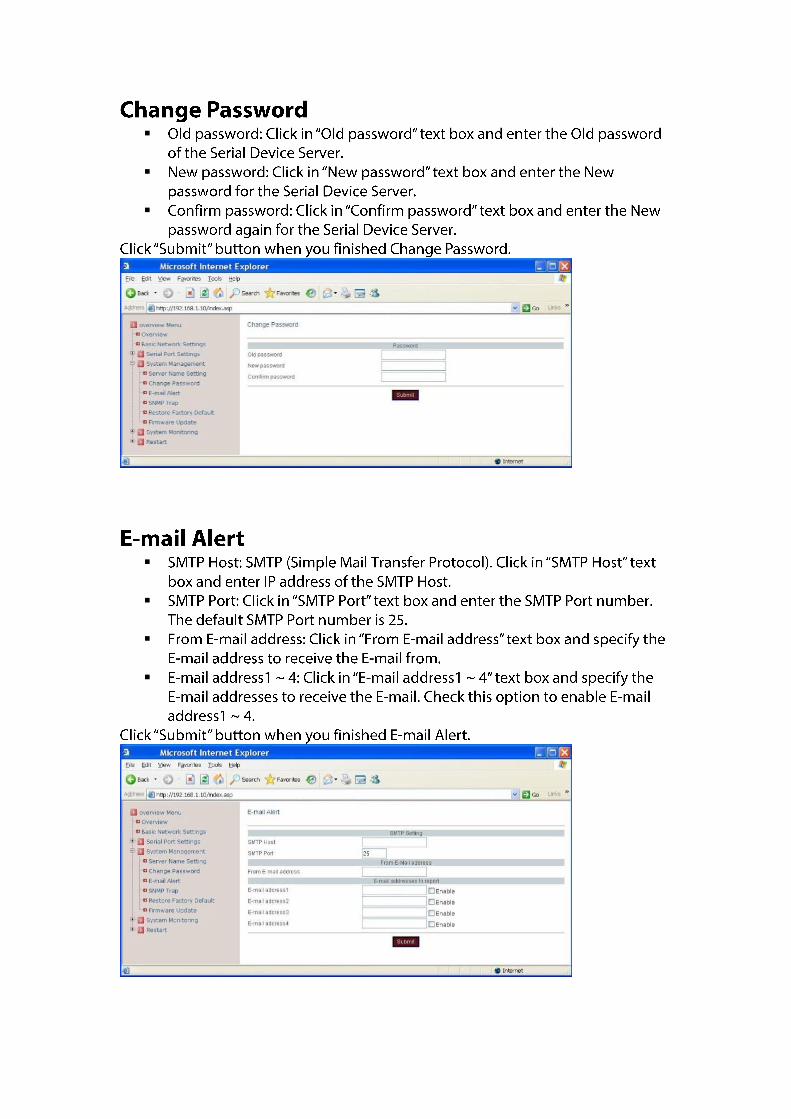
again for the Serial Device Server. SNMP Trap IP of remote SNMP trap receiver: Click in “IP of remote SNMP trap receiver” text box and enter IP address of the remote SNMP trap receiver. E-mail Alert 1. SMTP Setting: SMTP Host: SMTP (Simple Mail Transfer Protocol). Click in “SMTP Host” text box and
enter IP address of the SMTP Host. SMTP Port: Click in “SMTP Port” text box and enter the SMTP Port number. The default
SMTP Port number is 25. 2. From E-Mail address From E-mail address: Click in “From E-mail address” text box and specify the E-mail
address to receive the E-mail from. 3. E-mail addresses to report E-mail address1 ~ 4: Click in “E-mail address1 ~ 4” text box and specify the E-mail
addresses to receive the E-mail. Check this option to enable E-mail address1 ~ 4. Firmware Update Select file: Click the “Search File” button to search the firmware file to be updated to the Serial Device Server.
Click “Utility Setting” from “Setting” to configure the Serial Device Server. Environment 1. Auto-detect Device on start: Check this option to enable the Serial Device Server to
automatically detect whether the connected serial device is started up. 2. Auto-polling: Click in “Auto-polling” text box and type a period of Auto-polling time
assigned to Serial Device Server. The default Auto-polling is per 2 seconds.
Fig 83. Environment Load setting 1. Replace network setting: Check this option to replace the network setting of the Serial
Device Server when you load setting to the Serial Device Server.

2. Replace account and password: Check this option to replace the account and password of the Serial Device Server when you load setting to the Serial Device Server.
3. Replace host name: Check this option to replace the host name of the Serial Device Server when you load setting to the Serial Device Server.
4. Show this page when load file: Check this option to show this Utility Setting page when user loads setting to the Serial Device Server.
Fig 84. Load setting
Click “Monitoring” from menu bar to show as Fig 85.
Fig 85. Monitoring
Click “Port Status” from “Monitoring” to view the Port Status of the Serial Device Server.
Fig 86. Port Status

System User can view the System Log of the Serial Device Server.
Fig 87. System Event User can view the Event Log of the Serial Device Server.
Fig 88. Event
Click “Restart” from menu bar to show as Fig 89.

Fig 89. Monitoring
Click “Restart Port” from “Restart” to select the serial port on the Serial Device Server to be restarted.
Click “Restart System” from “Restart” to restart the Serial Device Server.
Fig 90. Restart System
Click “Restart All Ports” from “Restart” to select all serial ports on the Serial Device Server to be restarted.
Fig 91. Restart All Ports
Click “COM” from menu bar to show as Fig 92.

Fig 92. COM
Click “Create a new COM port” from “COM” to map a serial port to a COM port on a PC. The serial port on the Serial Device Server has to be set to Virtual Com mode when mapping COM port with Xport utility. Network setting 1. Remote IP address: Input the IP address of the remote Serial Device Server. 2. TCP port: Choose TCP port number assigned to the COM port. The default TCP port
number is 601. 3. Active auto-reconnect: Check this option to support Active auto-reconnect. The Xport
utility will automatically attempt to reconnect COM port to the serial port on the Serial Device Server.
4. Reconnect interval: The Xport utility will automatically attempt to reconnect COM port to the serial port on the Serial Device Server in defined time interval (Reconnect interval). The default Reconnect interval is 1000ms.
5. Cache data when connection was broken: Check this option to ensure that data is buffered if the connection is broken.
Fig 93. Network setting Serial setting 1. Serial port protocol: Choose Raw protocol or RFC2217 protocol. 2. Serial port preset signals: There are CTS, DSR, DCD, and RING serial port preset signals
that can be chosen. 3. Enable bitrate emulation: Check this option to limit data transmission speed to that was

specified to serial port. Transmission speed depends on bandwidth of the serial connection if bitrate emulation is disabled.
Fig 94. Serial setting
Click “Remove all COM ports” to remove all the COM ports and remove all the mapping from the serial ports to COM ports on a PC.
Fig 95. Remove all COM ports
Click “Help” from menu bar to show as Fig 96. Click “About utility” from “Help” to show the version of Xport utility as Fig 97.
Fig 96. Help

Fig 97. About utility

℃ ℉ ℉
℃ ℉ ℉
