iec 62439 -high availability automation...
TRANSCRIPT

© 2012 ABB
Highly Available Automation Networks
Standard Redundancy Methods
Rationales behind the
IEC 62439 standard suite
Hubert Kirrmann
ABB Switzerland Ltd,
Corporate Research

© 2012, ABB, 2
IEC 62439
Standard Redundancy
in Industrial EthernetScope
“The good thing about “Industrial Ethernet” standards is that there are so many
to choose from (IEC 61784) - you can even make your own”
It remains to be proved that the new networks are more reliable than the field busses that
they are supposed to replace.
However, customers require the new technology to be “at least as dependable as the one it
replaces”
But few “Industrial Ethernets” care about redundancy.
This talk shows what must be looked at when considering automation network redundancy
and which solutions IEC 62439 proposes

© 2012, ABB, 3
IEC 62439
Standard Redundancy
in Industrial EthernetIEC 62439 includes seven specifications
IEC 62439-1 defines the terms
specifies how to calculate the reliability and availability
specifies how to calculate the recovery time of RSTP (IEEE 802.2d)
IEC 62439-2 MRP (Media Redundancy Protocol), the Profinet ring protocol
supported by PNO, Siemens, Hirschmann, Phoenix-Contact
IEC 62439-3 Two seamless protocols (no recovery time)
PRP (Parallel Redundancy Protocol)
HSR (High-availability, Seamless Redundancy)
supported by ABB, Siemens, Hirschmann, ZHAW, Flexibilis
IEC 62439-4 CRP (coupled redundancy protocol) used by
supported by Fieldbus Foundation, Honeywell
IEC 62439-5 BRP, similar to CRP
supported by Rockwell & ODVA.
IEC 62439-6 DRP (Distributed Redundancy Protocol), similar to
MRP and including a clock synchronization, supported by SupCon (China)
IEC 62439-7 RRP (in preparation) another ring redundancy protocol
supported by RAPIEnet, LS Industrial Systems Co (Korea).

© 2012, ABB, 4
IEC 62439
Standard Redundancy
in Industrial Ethernet
1. Terms: availability and redundancy
2. Classification of requirements
3. Levels of device and network redundancy
4. Ethernet-based automation networks
5. Parallel (static) and serial (dynamic) redundancy
6. IEC 62439 solutions
7. Conclusion

© 2012, ABB, 5
IEC 62439
Standard Redundancy
in Industrial EthernetSome terms
Availability applies to repairable systems
Availability is the fraction of time a system is in the “up” state (capable of operation)
It is expressed in % (“duty cycle”), e.g. 99.99%.
repaired
time
up up up
state
repaired
down
MDT
Mean Up Time Mean Down
Time
repair
We consider systems in which availability is increased by introducing redundancy
(availability could also be increased by better parts, maintenance)
Redundancy is any resource that would not be needed if there were no failures.
We consider automatic insertion of redundancy in case of failure (fault-tolerant systems)
and automatic reinsertion after repair.

© 2012, ABB, 6
IEC 62439
Standard Redundancy
in Industrial EthernetAvailability states
first failure
(recovered)
successful
repair
2nd failure or
unsuccessful repair
not recovered first failure
downup
intactup
impaired
plant recovery (not considered here)
λ + λr
2λ (1-c)
2λc μ
ρ
we must consider all transitions, not just what happens after a failure

© 2012, ABB, 7
IEC 62439
Standard Redundancy
in Industrial EthernetClassification of redundancy methods (1)
static redundancy
(workby, parallel, massive)
dynamic redundancy
(standby, serial)
idle
input
E
D
E
D
E
D
E
D
output
input
outputtrusted
elements
fail-silent unit
error detection
(also of idle parts)
paradigm: spare tire paradigm: double tires in trucks
automation
system

© 2012, ABB, 8
IEC 62439
Standard Redundancy
in Industrial EthernetClassification of redundancy methods (2)
Dynamic (standby, serial) redundancy
Redundancy is not actively participating in
the control. A switchover logic decides to
insert redundancy and put it to work
This allows to:
+ share redundancy and load
+ implement partial redundancy
+ reduce the failure rate of redundancy
+ reduce common mode of errors
- but switchover takes time
Static (parallel, workby) redundancy
Redundancy is participating in the control, the
plant chooses the working unit it trusts.
This allows to:
+ provide seamless switchover
+ continuously exercise redundancy and
increase fault detection coverage
+ provide fail-safe behavior
- but total duplication is costly
© 2012, ABB, 9
IEC 62439
Standard Redundancy
in Industrial Ethernet
1. Terms: availability and redundancy
2. Classification of requirements
3. Levels of device and network redundancy
4. Industrial Ethernet topologies
5. Industrial Ethernet stack and redundancy
6. IEC 62439 solutions
7. Conclusion

© 2012, ABB, 10
IEC 62439
Standard Redundancy
in Industrial EthernetRequirements of fault-tolerant systems
degree of redundancy (full, partial duplication)
“Hamming Distance”: minimum number of components that must fail to stop service
guaranteed behavior when failing
fail-silent or not
switchover delay
duration of loss of service in case of failure
reintegration delay
duration of disruption to restore redundancy after repair (live insertion)
repair strategy
365/24 operation, scheduled maintenance, daily stops,…
supervision
detection and report of intermittent failures (e.g. health counters).
supervision of the redundancy (against lurking errors)
consequences of failure
partial / total system loss, graceful degradation, fault isolation
economic costs of redundancy
additional resources, mean time between repairs, mean time between system failure
factors depending on environment
(failure rate, repair rate) are not considered here.

© 2012, ABB, 11
IEC 62439
Standard Redundancy
in Industrial Ethernetswitchover time and grace time
The switchover delay is the most constraining factor in fault-tolerant systems.
The switchover delay is dictated by the grace time, i.e. the time that the plant allows for recovery
before taking emergency actions (e.g. emergency shut-down, fall-back mode).
E.g. recovery time after a communication failure must be shorter than the grace time to pass
unnoticed by the application.
The grace time classifies applications:
Uncritical < 10 s (not real time)
Enterprise Resource Planning, Manufacturing Execution
Automation general: < 1 s (soft real-time)
human interface, SCADA, building automation, thermal
Benign < 100 ms (real-time)
process & manufacturing industry, power plants,
Critical: < 10 ms (hard real time)
synchronized drives, robot control, substations, X-by-wire

© 2012, ABB, 12
IEC 62439
Standard Redundancy
in Industrial EthernetRecovery delay demands as shown in IEC 61850-5 Ed. 2
Communicating
partners
Service Application recovery
tolerated delay
Required
Communication
Recovery Time
SCADA to DAN, client-
server
IEC 61850-8-1 800 ms 400 ms
DAN to DAN interlocking IEC 61850-8-1 12 ms
(with Tmin set to 4 ms)
4 ms
DAN to DAN, reverse
blocking
IEC 61850-8-1 12 ms
(with Tmin set to 4 ms)
4 ms
Protection trip excluding
Bus Bar protection
IEC 61850-8-1 8 ms 4 ms
Bus Bar protection IEC 61850-9-2
on station bus
< 1 ms Bumpless
Sampled Values IEC 61850-9-2
on process bus
Less then two consecutive
samples
Bumpless
To fulfill these requirements, IEC 61850-8-1 and -9-2 uses redundancy solutions standardized for
Industrial Ethernet by IEC 62439-3.

© 2012, ABB, 13
IEC 62439
Standard Redundancy
in Industrial EthernetGrace time depends on the plant (typical figures)
chemical: 1scement: 10s
tilting train: 100ms X-by wire: 10ms substations: 5 ms
printing: 20 ms

© 2012, ABB, 14
IEC 62439
Standard Redundancy
in Industrial Ethernet
1. Terms: availability and redundancy
2. Classification of requirements
3. Levels of device and network redundancy
4. Industrial Ethernet topologies
5. Industrial Ethernet stack and redundancy
6. IEC 62439 solutions
7. Conclusion

© 2012, ABB, 15
IEC 62439
Standard Redundancy
in Industrial EthernetAutomation Networks: fully duplicated architecture
We consider networks for automation systems, consisting of nodes, bridges and links.
engineering
workplace
Field Bus
Firewall
Plant Network / Intranet
Field Bus
Client/server Network
3rd party
application
server
application
server
db
server
Workplaces
(clients)
Enterprise
Optimization
(clients)
Mobile
Operator
connectivity
server
Control Network
Programmable
Logic Controller
Redundant
PLC
touch-screen

© 2012, ABB, 16
IEC 62439
Standard Redundancy
in Industrial EthernetDevice and network redundancy (1)
1) No redundancy ( except fail-silent logic)
A A A
input output
2) Redundancy in the network: protects against network component failures
A A A
input output
bridge bridge bridge
bridge
network
nodes
nodes are singly attached
bridges and links
© 2012, ABB, 17
IEC 62439
Standard Redundancy
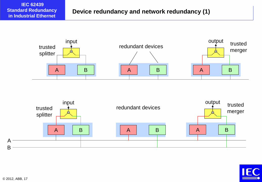
in Industrial EthernetDevice redundancy and network redundancy (1)
A A AB B B
input outputredundant devices
trusted
mergertrusted
splitter
input outputredundant devices
trusted
mergertrusted
splitter
A A A
A
B B B
B

© 2012, ABB, 18
IEC 62439
Standard Redundancy
in Industrial EthernetDevice and network redundancy (2)
3) Doubly attached nodes protects in addition against network adapter failures
A A A
A
B
input output
4) Redundant, singly attached nodes protect against node or network failures
A A A
A
B B B
B
input output
networks
© 2012, ABB, 19
IEC 62439
Standard Redundancy
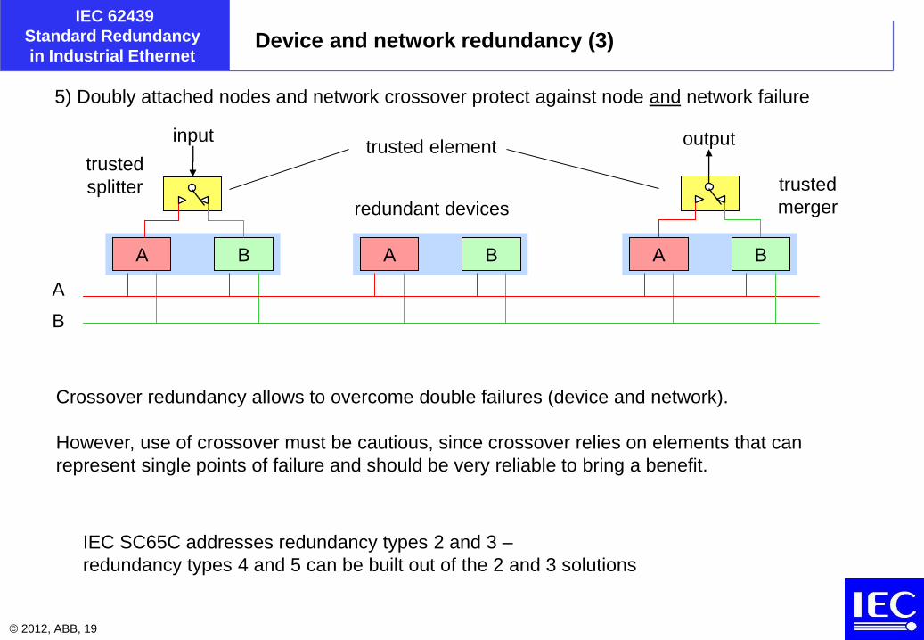
in Industrial EthernetDevice and network redundancy (3)
A B
input output
A B A B
Crossover redundancy allows to overcome double failures (device and network).
However, use of crossover must be cautious, since crossover relies on elements that can
represent single points of failure and should be very reliable to bring a benefit.
A
B
5) Doubly attached nodes and network crossover protect against node and network failure
trusted element
IEC SC65C addresses redundancy types 2 and 3 –
redundancy types 4 and 5 can be built out of the 2 and 3 solutions
trusted
splitterredundant devices
trusted
merger

© 2012, ABB, 20
IEC 62439
Standard Redundancy
in Industrial EthernetWorkby operation
input output
A B A B A B
A
B

© 2012, ABB, 21
IEC 62439
Standard Redundancy
in Industrial Ethernet
1. Terms: availability and redundancy
2. Classification of requirements
3. Levels of device and network redundancy
4. Industrial Ethernet topologies
5. Industrial Ethernet stack and redundancy
6. IEC 62439 solutions
7. Conclusion

© 2012, ABB, 22
IEC 62439
Standard Redundancy
in Industrial EthernetEthernet-based automation networks (tree topology)
local area
network
bridge
trunk
ports
inter-bridge
link
edge port
leaf link
leaf
links
inter-
bridge
link
edge port
end
node
bridgebridge
end
node
end
node
end
node
end
node
end
node
end
node
bridge
end
node
end
node
bridge
end
nodeend
node
end
nodeend
node
in principle no redundancy
© 2012, ABB, 23
IEC 62439
Standard Redundancy
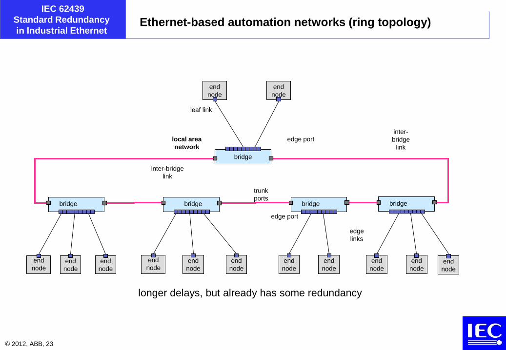
in Industrial EthernetEthernet-based automation networks (ring topology)
local area
network
bridge
trunk
ports
inter-bridge
link
edge port
leaf link
edge
links
inter-
bridge
link
edge port
end
node
bridgebridge
end
node
end
node
end
node
end
node
end
node
end
node
bridge
end
node
end
node
bridge
end
nodeend
node
end
nodeend
node
longer delays, but already has some redundancy

© 2012, ABB, 24
IEC 62439
Standard Redundancy
in Industrial Ethernet
bridge
Ethernet-based automation networks (ring of nodes)
This topology is becoming popular since it suppresses the (costly) bridges and allows a simple
linear cabling scheme, while giving devices a redundant connection.
Operation is nevertheless serial redundancy, i.e. requires a certain time
to change the routing.
Devices are doubly-attached, but do not operated in parallel.
bridge
element
singly
attached
device

© 2012, ABB, 25
IEC 62439
Standard Redundancy
in Industrial EthernetDynamic and static redundancy in networks
network BStatic
network A
bridge
Dynamic
in case of failure, bridges route the traffic over an other port – devices are singly attached
in case of failure the doubled attached nodes work with the remaining channel.
Well-known in the fieldbus workd
bridge bridge bridgebridge
bridge bridge
© 2012, ABB, 26
IEC 62439
Standard Redundancy
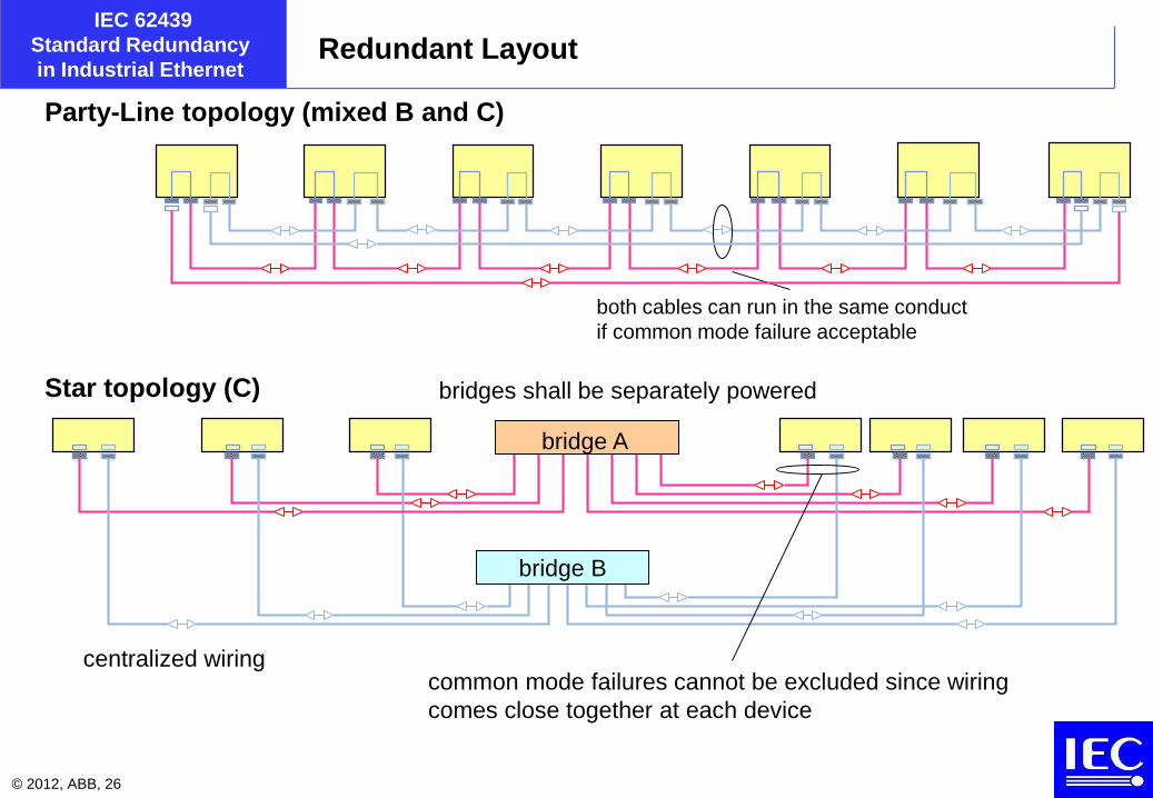
in Industrial EthernetRedundant Layout
centralized wiring
bridge B
Star topology (C)
Party-Line topology (mixed B and C)
both cables can run in the same conduct
if common mode failure acceptable
bridge A
common mode failures cannot be excluded since wiring
comes close together at each device
bridges shall be separately powered

© 2012, ABB, 27
IEC 62439
Standard Redundancy
in Industrial Ethernet
1. Terms: availability and redundancy
2. Classification of requirements
3. Levels of device and network redundancy
4. Industrial Ethernet topologies
5. Industrial Ethernet stack and redundancy
6. IEC 62439 solutions
7. Conclusion

© 2012, ABB, 28
IEC 62439
Standard Redundancy
in Industrial EthernetWhat makes Industrial Ethernet special
Most “Industrial Ethernet” uses the classical TCP-UDP-IP stack and in addition a layer 2 traffic for
real-time data (but some use UDP) and a clock synchronization (IEEE 1588)
MAC/PHY Ethernet 802.3
TCP RFC 793UDP
IP
Client /
Server
services
PT=0800Link Layer
applicationapplicationapplication
SNTP,
PTP L3,
(SNMP)
ARP
802.p1 / 802.1QPriority tag
PT=0806PTID=8100 802.2
spanning
tree(802.1d)
Hard Real-Time stack
void
Soft-Time stack
ICMP
Layer 7
Publisher/
SubscriberLayer 2
Publisher /Subscriber
01
void
Therefore, Industrial Ethernet redundancy must operate at level 2

© 2012, ABB, 29
IEC 62439
Standard Redundancy
in Industrial EthernetCommunication stack and redundancy
The redundant Ethernet solutions distinguish themselves by:
- the OSI level at which switchover or selection is performed.
- whether they operate with dynamic or static redundancy
Industrial protocols operate both at network layer (IP) and at link layer (e.g. Real Time traffic, clock
synchronization traffic),
Redundancy only at network level is not sufficient, it must be implemented at layer two to account
for industrial Ethernets that use these layers.
Since standard methods handle effectively redundancy at the network layer ( TCP / IP), network
level redundancy is separated from the device-level redundancy.

© 2012, ABB, 30
IEC 62439
Standard Redundancy
in Industrial EthernetCommercial solutions to redundancy in the nodes
physical layer
(drivers)
1 Ethernet controller
link layer
(drivers and
controller)
2 MAC Addresses
network layer
(drivers, controller and
network routing)
2 IP Addresses
only redundancy
within the network
1N
1
2
3
4
7
Net (IP)
Link
Phy
TRP
Link
Phy Phy
TRP
Net (IP)
Link
Phy Phy
Link
TRP
Net (IP)
Link
Phy Phy
Link
Net (IP)
Net (IP)
APL APL APL
TRP
APL
2
3
4
7
2
3
4
7
1
2
3
4
7
1 1 1
TRP
Net (IP)
Link
Phy Phy
Link
APL
2
3
4
7
link layer
(drivers and
controller)
1 MAC Addresses
A
B
bridge
1
2
(no duplication of nodes)
the level of redundancy can be identified by the addresses used

© 2012, ABB, 31
IEC 62439
Standard Redundancy
in Industrial EthernetMethods for dynamic redundancy in networks
-IP protocol Layer 3 (network) 10s or more – unsuited for Industrial Ethernet
-RSTP (IEEE 802.1D) Layer 2 (bridges): 1 s typical, less in fixed topography
-HyperRing Layer 2 (ring) 50 ms (typical, depends on ring size)
-CRP Layer 2 400 ms (typical, depends on LAN size)
-BRP Layer 2 10 ms (typical, depends on beacon frequency)
-DRP Layer 2 ?
-RRP Layer 2 ?
-The switchover time of dynamic redundancy is limited by the detection time of the failure.
(or rather, by the interval at which the non-failure is checked, since failures can’t be relied upon to
announce themselves).

© 2012, ABB, 32
IEC 62439
Standard Redundancy
in Industrial Ethernet
1. Terms: availability and redundancy
2. Classification of requirements
3. Levels of device and network redundancy
4. Industrial Ethernet topologies
5. Industrial Ethernet stack and redundancy
6. IEC 62439 solutions
7. Conclusion

© 2012, ABB, 33
IEC 62439
Standard Redundancy
in Industrial EthernetRules of order of WG15
1) the standard redundancy solution is independent of the higher protocols used
2) the standard shall be compatible with existing equipment, especially commercial PCs and
bridges, where no redundancy is used
3) the standard shall define the layout rules and especially the integration of different levels of
redundancy
4) the standard shall define means to supervise the redundancy, e.g. using SNMP
5) the standard shall define scenarios for life insertion and reintegration of repaired
components
6) the standard shall define measurable performance goals, such as switchover times and
reintegration time
7) if several solutions emerge, the standard shall specify their (distinct) application domains
and recommendation for their use
WG15 shall not consider safety or security issues – for this there are other standards.

© 2012, ABB, 34
IEC 62439
Standard Redundancy
in Industrial EthernetIEC 62439 solutions
WG15 decided to address requirements separately
A) general automation systems
the standard recommends to use RSTP
(base: IEEE standards, RSTP) – no need for a new standard < 500 ms
B) benign real-time systems that are cost-sensitive, grace time < 200 ms
the standard shall define an adequate bridge redundancy scheme
and redundant devices attachment.
(base: RSTP and further developments – solution: MRP, DRP, RRP
C) critical real-time systems that require higher coverage, grace time 0 ms
the standard shall define a parallel network solutions and redundant
device attachment.
(base: ARINC AFDX and similar – solution PRP, HSR
D) legacy solutions based on Fieldbus Foundation
CRP <
© 2012, ABB, 35
IEC 62439
Standard Redundancy
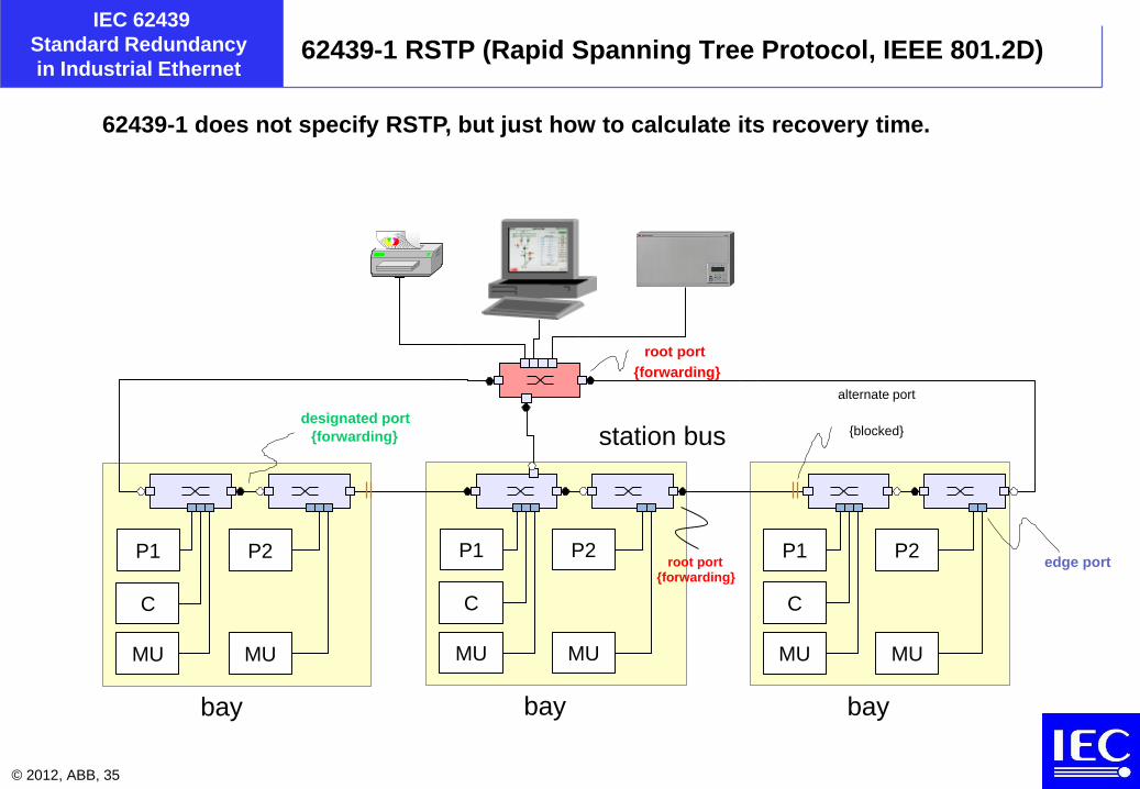
in Industrial Ethernet62439-1 RSTP (Rapid Spanning Tree Protocol, IEEE 801.2D)
62439-1 does not specify RSTP, but just how to calculate its recovery time.
P1
C
MU
bay
P2
MU
P1
C
MU
bay
P2
MU
P1
C
MU
bay
P2
MU
edge portroot port{forwarding}
designated port
{forwarding}
alternate port
{blocked}
root port
{forwarding}
station bus
© 2012, ABB, 36
IEC 62439
Standard Redundancy
in Industrial EthernetRSTP performance
+: IEEE standard, field proven, large market, cheap
+: no impact on the end nodes (all end nodes are singly attached)
+: can be implemented in the nodes if the nodes contain a bridge element
-: RSTP is in fame of being rather slow (some seconds switchover time).
However, if its topology is fixed, RSTP bridges can learn the topography
and calculate alternate paths in case one should fail. Some manufacturers claim recovery
delays <100 ms for selected configurations

© 2012, ABB, 37
IEC 62439
Standard Redundancy
in Industrial Ethernet62439-2 MRP (Siemens-Hirschmann hyperring)
intact ring MRC
end
node
end
node
end
node
… end
node
end
node
end
node
…end
node
end
node
end
node
…
MRM
end
node
end
node
end
node
end
node
end
node
end
node
MRCMRCMRC
broken ring
the Medium Redundancy Master (MRM) controls the ring
the Medium Redundancy Clients (MRC) close the ring
MRC
end
node
end
node
end
node
… end
node
end
node
end
node
…end
node
end
node
end
node
…
MRM
end
node
end
node
end
node
end
node
end
node
end
node
MRCMRCMRC
© 2012, ABB, 38
IEC 62439
Standard Redundancy
in Industrial EthernetMRP performance
The MRM checks the integrity of the ring by sending in both direction test frames.
These test frames are forwarded by all intact bridges and inter-bridge links.
If the MRM does not receive its own frames over its other interface, it closes the ring
at its location, reestablishing traffic.
Supervision frames allows to locate the source of the trouble.
+: fast switchover (< 200ms worst case)
+: no impact on the nodes
+: no increase in network infrastructure.
-: MRP bridges are not compatible with RSTP bridges, limited market
-: limited to one ring topology

© 2012, ABB, 39
IEC 62439
Standard Redundancy
in Industrial EthernetCRP performance
The Coupled Redundancy Protocol is derived from the Fieldbus Foundation H3 network.
It uses two separate networks, to which devices are attached through two network adapters.
The networks are used alternatively rather than in parallel.
+: provides cross-redundancy (double fault network and node)
+: provides protection against adapter failures
-more than double network costs with respect to non-redundant networks
-large effort for building doubly-attached nodes.
-switchover time not specified

© 2012, ABB, 40
IEC 62439
Standard Redundancy
in Industrial Ethernet62439-3.4 Parallel Redundancy Protocol
A
B
send
Tx RxTx Tx RxTx Rx
receive
send on both lines: each frame is send on both A and B lines, frames over A and B have
different transmission delays (or may not arrive at all)
receive on both lines: the stack receives both frames from both lines treated as equal, a
"merge layer" between the link and the network layer suppresses duplicates.
network layer
transport layer
send
Rx
receive
bus controller
layer
redundancy
manager
transceivers
A B A B
same
interface
publisher/
subscriber network layer
transport layerpublisher/
subscriber
upper layers
lane A
lane B

© 2012, ABB, 41
IEC 62439
Standard Redundancy
in Industrial EthernetPRP layout examples
switch
DANP
switch
local area network B
DANP
switchswitch
switch
SAN
switch
DANP DANP
local area network A
DANPDANP
DANP = Doubly Attached Node using PRP
DANP SAN
PRP “A” frames
PRP “B” frames
standard frames
SAN
SAN
source
destinations destinations

© 2012, ABB, 42
IEC 62439
Standard Redundancy
in Industrial EthernetPRP suppressing duplicates
To ease duplicate rejection, PRP nodes append a sequence number to the frames
along with a size field that allows to determine that the frame belongs to the PRP
protocol. This trailer is invisible to the higher layers (considered as padding)
Receivers discard duplicates using a variety of methods
- each frame is extended by a sequence counter, a lane indicator, a size field and a
suffix * inserted after the payload to remain invisible to normal traffic.
- the sender inserts the same sequence counter into both frames of a pair, and
increments it by one for each frame sent.
- the receiver keeps track of the sequence counter for each for each source MAC
address it receives frames from. Frames with the same source and counter value
coming from different lanes are ignored.
timedestination source LLC FCSpayloadpreamble sizesequence
counter lan
e
original Ethernet frame
PRP
suffix
© 2012, ABB, 43
IEC 62439
Standard Redundancy
in Industrial EthernetPRP performance
+ PRP allows seamless switchover, no frames are lost
+ During normal operation, PRP reduces the loss rate
+ doubly attached nodes (DANP) are simple to build
+ SANs can readily communicate with DANPs
+ PRP checks the presence of nodes by periodical supervision frames that also
indicate which nodes participate in the protocol and which not
- double network costs
- SAN of one LAN cannot communicate directly with SANs of the other LAN
- frame size must be limited to prevent frames from becoming longer than the IEEE 802.3
maximum size (but most bridges and Ethernet controllers accept frames up to 1536 octets)

© 2012, ABB, 44
IEC 62439
Standard Redundancy
in Industrial Ethernet62439-3.5 HSR (High availability seamless redundancy)
Nodes are arranged as a ring, each node has two identical interfaces, port A and port B.
For each frame to send (“C”-frame), the source node sends two copies over port A and B.
Each node relays a frame it receives from port A to port B and vice-versa, except if it already forwarded it.
The destination nodes consumes the first frame of a pair and discards the duplicate.
In case of interruption of the ring, frames still continue to be received over the intact path.
“A” frames
“B” frames
standard frames
removal from the ring
DANH
node
CPU
destinations
source
„A“-frame
(HSR tagged)
„B“-frame
(HSR tagged)
„C“-frame
(untagged)
„D“-frame
(untagged)
AB
destinations
DANHDANHDANHDANH
DANHDANH

© 2012, ABB, 45
IEC 62439
Standard Redundancy
in Industrial EthernetHSR topology: rings of rings
HSR
standard Ethernet
quadbox
workstation
no RSTP protocol any more (but can be used)
note that level 3 is singly attached (only one quadbox)
GPS
printer
maintenance laptop

© 2012, ABB, 46
IEC 62439
Standard Redundancy
in Industrial EthernetHSR performance
+ HSR allows bumpless switchover, no frames are lost
+ During normal operation, HSR reduces the loss rate
+ HSR checks the presence of nodes by periodical supervision frames that also
indicate which nodes participate in the protocol and which not
+ cost-effective solution once devices include HSR bridgeing hardware
+ flexible topology: rings and rings of rings
+ can be connected with PRP
+ full concept for IEEE 1588 clock synchronization
-: doubly attached devices require an initial development cost (hardware)
-: SANs must be attached through RedBoxes

© 2012, ABB, 47
IEC 62439
Standard Redundancy
in Industrial EthernetIEC 62439-4 Coupled Redundancy Protocol
Honeywell contribution
Redundancy- in-the-nodes, legacy from the Fieldbus Foundation protocol
All traffic must be routed through the inter-LAN links.
Allows SAN from both LANs to communicate (unlike PRP)
bridge bridge
LAN_B
top bridgetop bridge
bridgebridge
LAN_A
inter-LAN links
DANCSANC
A2 DANC DANC DANCSAN
B1
SAN
B2
DANC DANCSAN
A1

© 2012, ABB, 48
IEC 62439
Standard Redundancy
in Industrial EthernetIEC 62439-5 Beacon Redundancy Protocol
bridge bridge
LAN_B
top bridge Btop bridge A
bridgebridge
LAN_A
inter-LAN links
DANCSANC
A2 DANC DANC DANCSAN
B1
SAN
B2
DANC DANCSAN
A1
Rockwell contribution
Adds to the CRP principle two beacon nodes for faster recovery, at a high communication cost.
Endorsed by ODVA, advertised for CIP, but no products known.
Some unsolved technical issues.
beacon
nodebeacon
node

© 2012, ABB, 49
IEC 62439
Standard Redundancy
in Industrial EthernetIEC 62439-6 Distributed Redundancy Protocol
F F F F F F F F
B F F F F F F F
Chinese contribution.
Adds to the MRP ring principle a clock synchronization protocol to achieve TDMA behaviour.
Double ring possible.
Benefits unclear

© 2012, ABB, 50
IEC 62439
Standard Redundancy
in Industrial Ethernet
1. Terms: availability and redundancy
2. Classification of requirements
3. Levels of device and network redundancy
4. Industrial Ethernet topologies
5. Industrial Ethernet stack and redundancy
6. IEC 62439 solutions
7. Conclusion

© 2012, ABB, 51
IEC 62439
Standard Redundancy
in Industrial EthernetConclusion
IEC 62439 satisfies the needs of the Industrial Ethernets belonging to the IEC 61784
suite with eight solutions:
-RSTP: mainstream, sufficient for most applications–with improvements for fixed configuration
-MRP: ring-based protocol for demanding automation networks and singly attached nodes,
especially useful with bridgeing nodes.
-PRP: seamless protocol suited for critical applications requiring doubly attached nodes.
-HSR: seamless protocol suited for critical applications, cost efficient ring structure
-CRP: Honeywell’s legacy protocol for Fieldbus Foundation, using doubly attached nodes.
-BRP: Rockwell’s extension of CRP for ODVA/CIP
-DRP: SupCon’s extension of MRP with a clock
-RRP: (in preparation) LSIS’s extension of DRP.
IEC 61850 decided in favor of RSTP, PRP and HSR, while PNO selected MRP.
the future of the other solutions is clouded.