prp - seamless redundancy for industrial...
TRANSCRIPT
INTERNATIONAL
ELECTROTECHNICAL
COMMISSION
PRP - Parallel Redundancy Protocol
An IEC standard for a seamless
redundancy method using parallel
networks, applicable to hard-real time
Industrial Ethernet
Prof. Dr. Hubert Kirrmann,
Solutil, Switzerland
2017 February 4
IEC 62439-3 §4
picture from shawnhallwachs' photostream
Prof. Dr. Hubert Kirrmann, Solutil, Switzerland
2017 February 8
2 IEC SC65C WG15 © 2017 HK 2017-02-08
IEC 62439-3.4 (PRP)Parallel Redundancy Protocol Summary
PRP (IEC 62439-3 Clause 4)
- Ethernet redundancy method independent of any industrial Ethernet protocol
- Seamless switchover and recovery in case of failure supports real-time communication
- Supervises redundancy continuously for device management
- Suitable for hot swap - 24h/365d operation in substations
- Allows mixing devices with single and double network attachment on the same LAN
- Allows to connect laptops and workstations to the network with standard Ethernet adapters
- Supports any topology
- Suited particularly for substation automation, high-speed drives and transportation.
3 IEC SC65C WG15 © 2017 HK 2017-02-08
IEC 62439-3.4 (PRP)Parallel Redundancy Protocol Highly available automation networks
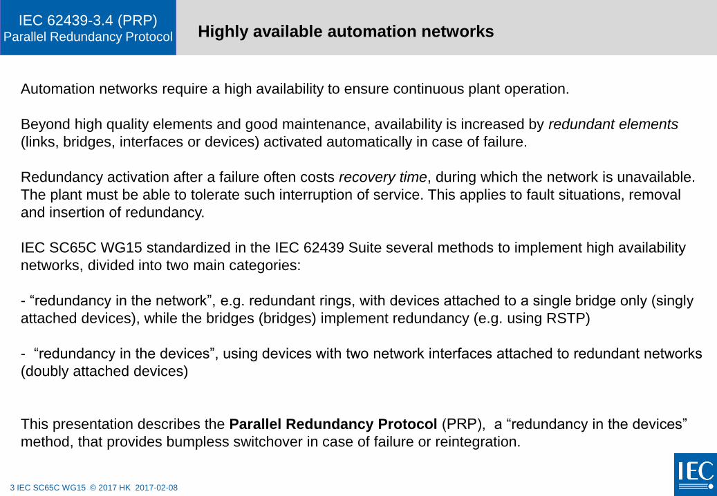
Automation networks require a high availability to ensure continuous plant operation.
Beyond high quality elements and good maintenance, availability is increased by redundant elements
(links, bridges, interfaces or devices) activated automatically in case of failure.
Redundancy activation after a failure often costs recovery time, during which the network is unavailable.
The plant must be able to tolerate such interruption of service. This applies to fault situations, removal
and insertion of redundancy.
IEC SC65C WG15 standardized in the IEC 62439 Suite several methods to implement high availability
networks, divided into two main categories:
- “redundancy in the network”, e.g. redundant rings, with devices attached to a single bridge only (singly
attached devices), while the bridges (bridges) implement redundancy (e.g. using RSTP)
- “redundancy in the devices”, using devices with two network interfaces attached to redundant networks
(doubly attached devices)
This presentation describes the Parallel Redundancy Protocol (PRP), a “redundancy in the devices”
method, that provides bumpless switchover in case of failure or reintegration.

4 IEC SC65C WG15 © 2017 HK 2017-02-08
IEC 62439-3.4 (PRP)Parallel Redundancy Protocol
PRP principles
5 IEC SC65C WG15 © 2017 HK 2017-02-08
IEC 62439-3.4 (PRP)Parallel Redundancy Protocol PRP Principle Network Architecture
bridge
DANP
bridge
local area network B
DANP
bridgebridge
bridge
SAN
bridge
DANP DANP
local area network A
DANP DANP
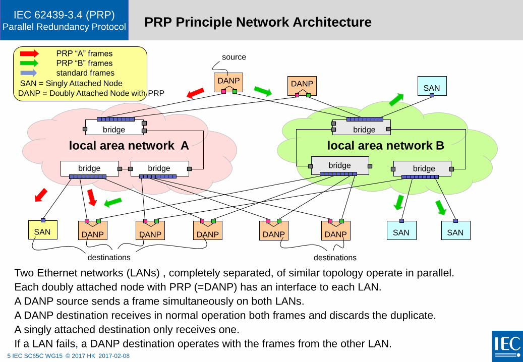
Two Ethernet networks (LANs) , completely separated, of similar topology operate in parallel.
Each doubly attached node with PRP (=DANP) has an interface to each LAN.
A DANP source sends a frame simultaneously on both LANs.
A DANP destination receives in normal operation both frames and discards the duplicate.
A singly attached destination only receives one.
If a LAN fails, a DANP destination operates with the frames from the other LAN.
DANP SAN
PRP “A” frames
PRP “B” frames
standard frames
SAN = Singly Attached NodeSAN
SAN
source
destinations destinations
DANP = Doubly Attached Node with PRP
6 IEC SC65C WG15 © 2017 HK 2017-02-08
IEC 62439-3.4 (PRP)Parallel Redundancy Protocol PRP characteristics
PRP allows to attach nodes to a network by redundant network interfaces and links:
• Addresses high availability networks tolerating any single network component failure
• Provides seamless switchover (zero nanoseconds) in case of network failure.
• Transparent to the application
• Can be used with any Industrial Ethernet on layer 2 or above
• Does not rely on higher layer protocols to operate or be configured
• Allows nodes not equipped for redundancy to communicate with redundant nodes
• Uses off-the shelf components (network interfaces, controllers, bridges and links)
• Can be used with any topology (tree, ring,…)
7 IEC SC65C WG15 © 2017 HK 2017-02-08
IEC 62439-3.4 (PRP)Parallel Redundancy Protocol PRP Node Operation
A
B
send
duplicate
Tx RxTx Tx RxTx Rx
duplicate
discard
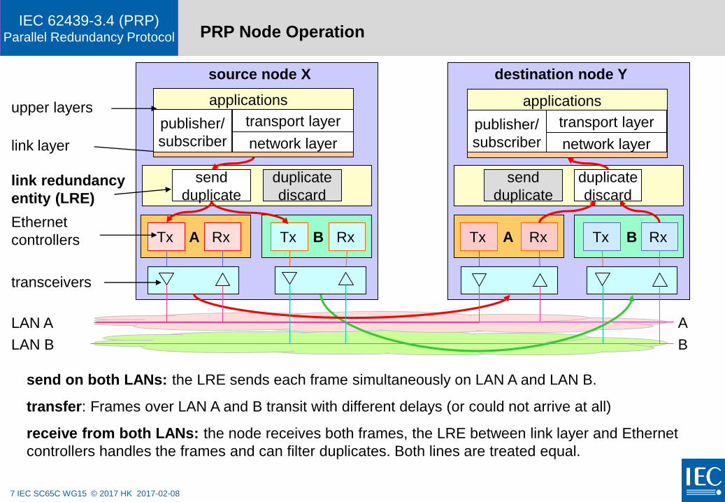
send on both LANs: the LRE sends each frame simultaneously on LAN A and LAN B.
transfer: Frames over LAN A and B transit with different delays (or could not arrive at all)
receive from both LANs: the node receives both frames, the LRE between link layer and Ethernet
controllers handles the frames and can filter duplicates. Both lines are treated equal.
network layer
transport layer
send
duplicate
Rx
duplicate
discard
Ethernet
controllers
link redundancy
entity (LRE)
transceivers
A B A B
publisher/
subscriber
upper layers
LAN A
LAN B
applications
network layer
transport layerpublisher/
subscriber
applications
link layer
source node X destination node Y
8 IEC SC65C WG15 © 2017 HK 2017-02-08
IEC 62439-3.4 (PRP)Parallel Redundancy Protocol Why a layer 2 redundancy ?
Many Industrial Ethernet networks operate with a layer 2 (Link Layer) protocol.
One motivation for this is the use of the publisher-subscriber method, that relies on
broadcast of source-addressed data within the MAC broadcast domain.
This excludes a redundancy scheme based on routers (Layer 3).
Each node in PRP has the same MAC address on both network interfaces.
Therefore, management protocols such as ARP operate as usual and assign that MAC address
to the IP address(es) of that node. Tools based on SNMP also operate as usual.
Redundancy methods must operate on Layer 2 (Logical Link) to address Industrial
Ethernets with hard real-time stacks built on Layer 2, such as IEC61850.
9 IEC SC65C WG15 © 2017 HK 2017-02-08
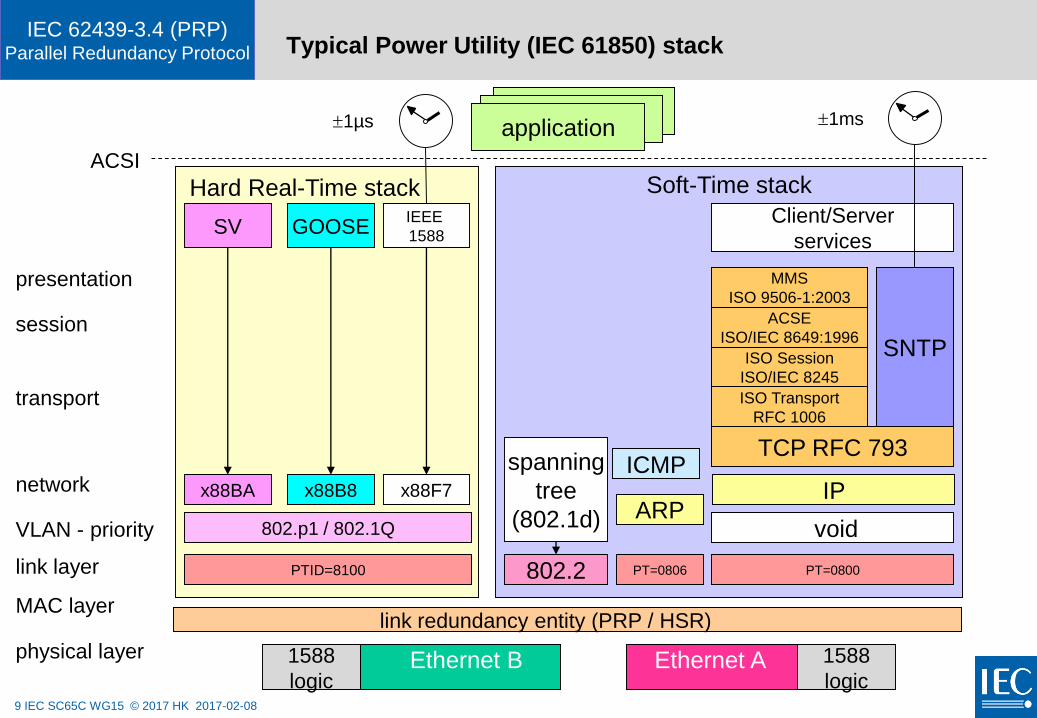
IEC 62439-3.4 (PRP)Parallel Redundancy Protocol Typical Power Utility (IEC 61850) stack
link layer
VLAN - priority
physical layer
network
transport
session
presentation
MAC layer
TCP RFC 793
IP
ISO Transport
RFC 1006
ISO Session
ISO/IEC 8245
ACSE
ISO/IEC 8649:1996
MMS
ISO 9506-1:2003
Client/Server
services
ACSI
PT=0800
applicationapplicationapplication
SNTP
ARP802.p1 / 802.1Q
PT=0806PTID=8100 802.2
spanning
tree
(802.1d)
x88F7x88B8x88BA
IEEE
1588GOOSESV
Hard Real-Time stack
void
Soft-Time stack
ICMP
link redundancy entity (PRP / HSR)
Ethernet B Ethernet A
1ms1µs
1588
logic
1588
logic
10 IEC SC65C WG15 © 2017 HK 2017-02-08
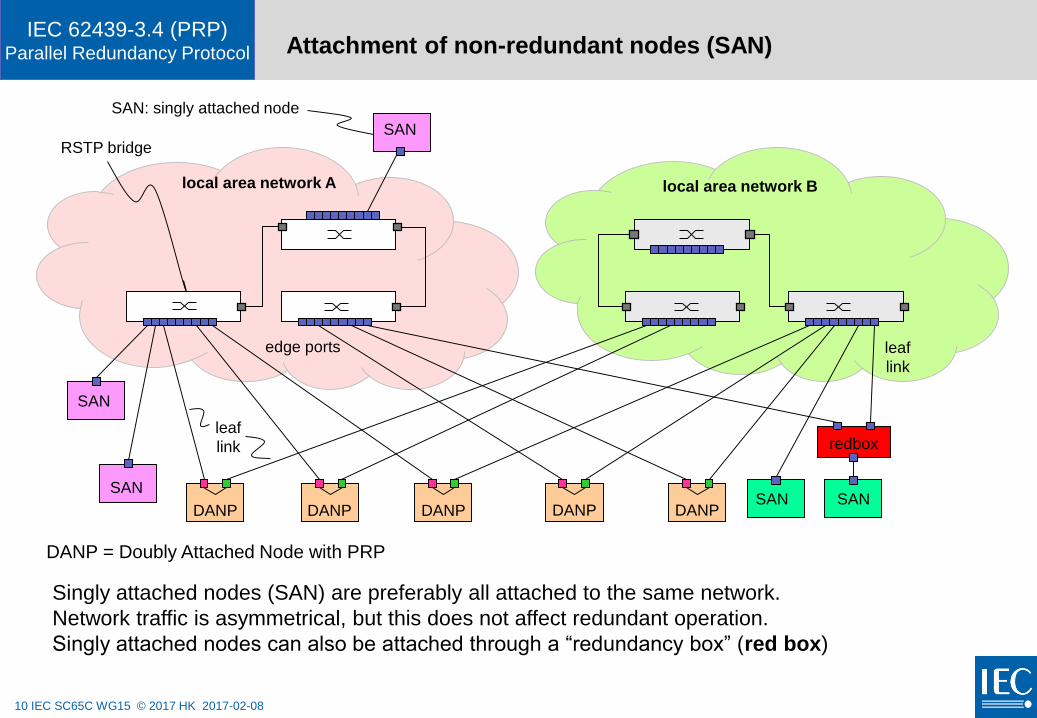
IEC 62439-3.4 (PRP)Parallel Redundancy Protocol Attachment of non-redundant nodes (SAN)
edge ports
local area network B
leaf
link
SAN
leaf
link
RSTP bridge
local area network A
SAN
SAN
SAN
redbox
SAN
Singly attached nodes (SAN) are preferably all attached to the same network.
Network traffic is asymmetrical, but this does not affect redundant operation.
Singly attached nodes can also be attached through a “redundancy box” (red box)
DANP = Doubly Attached Node with PRP
DANP DANPDANP DANPDANP
SAN: singly attached node
11 IEC SC65C WG15 © 2017 HK 2017-02-08
IEC 62439-3.4 (PRP)Parallel Redundancy Protocol
bridge B
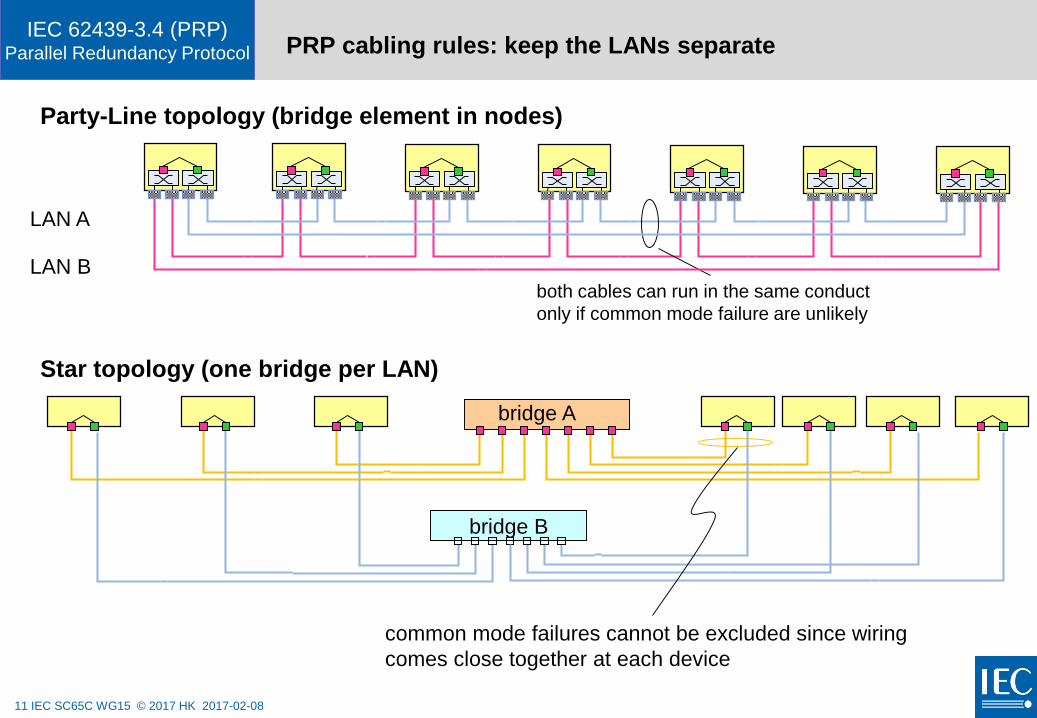
PRP cabling rules: keep the LANs separate
Star topology (one bridge per LAN)
Party-Line topology (bridge element in nodes)
both cables can run in the same conduct
only if common mode failure are unlikely
bridge A
common mode failures cannot be excluded since wiring
comes close together at each device
LAN A
LAN B
12 IEC SC65C WG15 © 2017 HK 2017-02-08
IEC 62439-3.4 (PRP)Parallel Redundancy Protocol
How PRP discards duplicates
13 IEC SC65C WG15 © 2017 HK 2017-02-08
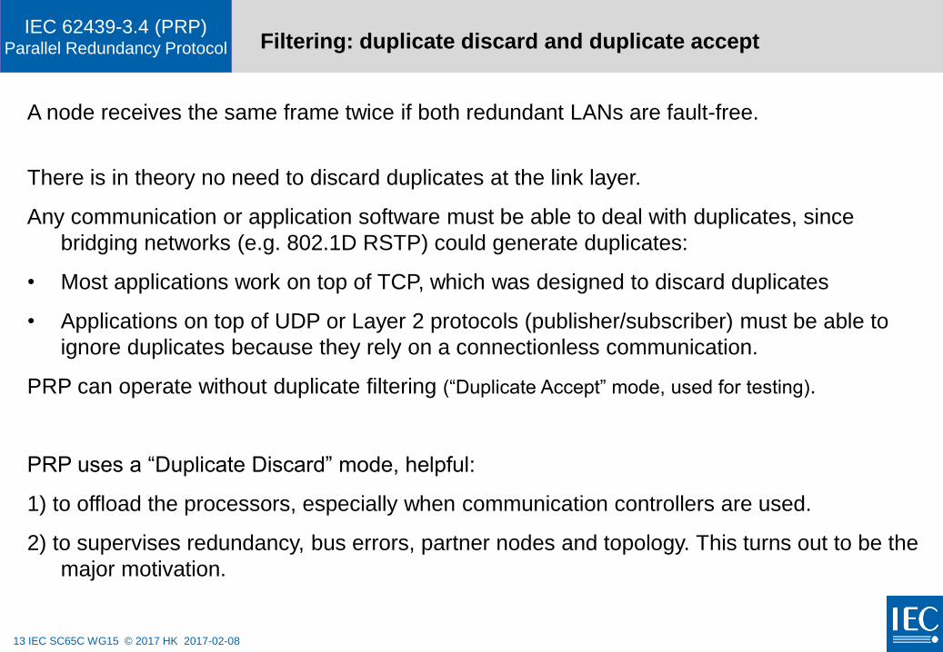
IEC 62439-3.4 (PRP)Parallel Redundancy Protocol Filtering: duplicate discard and duplicate accept
A node receives the same frame twice if both redundant LANs are fault-free.
There is in theory no need to discard duplicates at the link layer.
Any communication or application software must be able to deal with duplicates, since
bridging networks (e.g. 802.1D RSTP) could generate duplicates:
• Most applications work on top of TCP, which was designed to discard duplicates
• Applications on top of UDP or Layer 2 protocols (publisher/subscriber) must be able to
ignore duplicates because they rely on a connectionless communication.
PRP can operate without duplicate filtering (“Duplicate Accept” mode, used for testing).
PRP uses a “Duplicate Discard” mode, helpful:
1) to offload the processors, especially when communication controllers are used.
2) to supervises redundancy, bus errors, partner nodes and topology. This turns out to be the
major motivation.
14 IEC SC65C WG15 © 2017 HK 2017-02-08
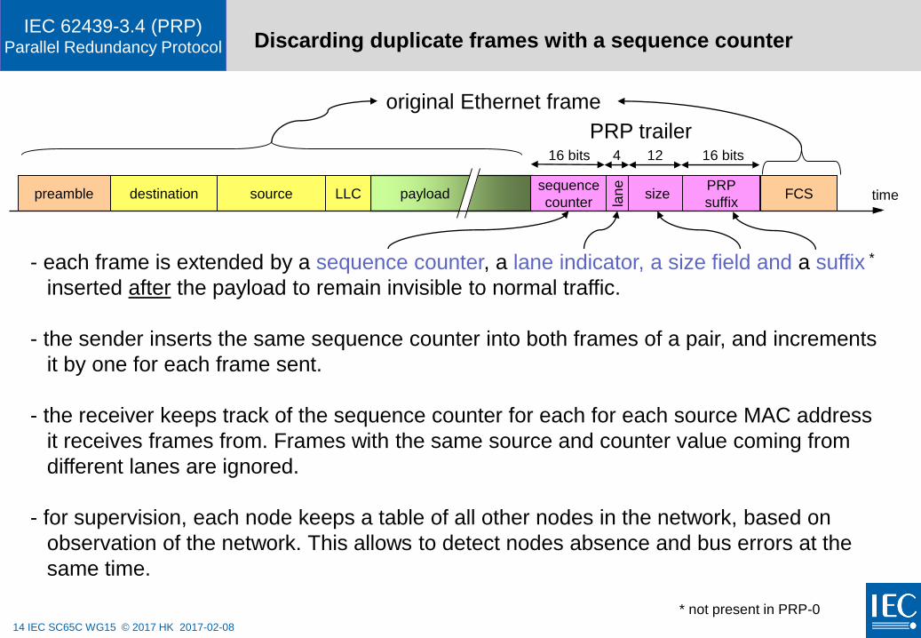
IEC 62439-3.4 (PRP)Parallel Redundancy Protocol Discarding duplicate frames with a sequence counter
- each frame is extended by a sequence counter, a lane indicator, a size field and a suffix *
inserted after the payload to remain invisible to normal traffic.
- the sender inserts the same sequence counter into both frames of a pair, and increments
it by one for each frame sent.
- the receiver keeps track of the sequence counter for each for each source MAC address
it receives frames from. Frames with the same source and counter value coming from
different lanes are ignored.
- for supervision, each node keeps a table of all other nodes in the network, based on
observation of the network. This allows to detect nodes absence and bus errors at the
same time.
timedestination source LLC FCSpayloadpreamble sizesequence
counter lan
e
original Ethernet frame
PRP
suffix
* not present in PRP-0
16 bits 12 16 bits4
PRP trailer
15 IEC SC65C WG15 © 2017 HK 2017-02-08
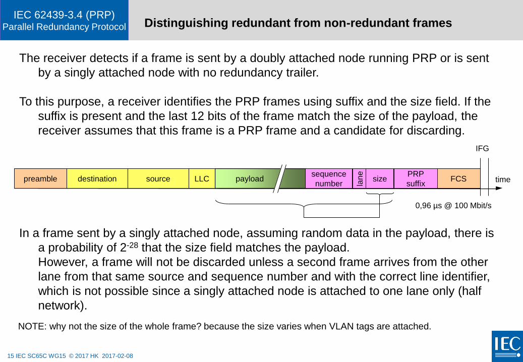
IEC 62439-3.4 (PRP)Parallel Redundancy Protocol Distinguishing redundant from non-redundant frames
timedestination source LLC FCSpayloadpreamble sizesequence
number lan
e
In a frame sent by a singly attached node, assuming random data in the payload, there is
a probability of 2-28 that the size field matches the payload.
However, a frame will not be discarded unless a second frame arrives from the other
lane from that same source and sequence number and with the correct line identifier,
which is not possible since a singly attached node is attached to one lane only (half
network).
The receiver detects if a frame is sent by a doubly attached node running PRP or is sent
by a singly attached node with no redundancy trailer.
To this purpose, a receiver identifies the PRP frames using suffix and the size field. If the
suffix is present and the last 12 bits of the frame match the size of the payload, the
receiver assumes that this frame is a PRP frame and a candidate for discarding.
PRP
suffix
IFG
0,96 µs @ 100 Mbit/s
NOTE: why not the size of the whole frame? because the size varies when VLAN tags are attached.
16 IEC SC65C WG15 © 2017 HK 2017-02-08
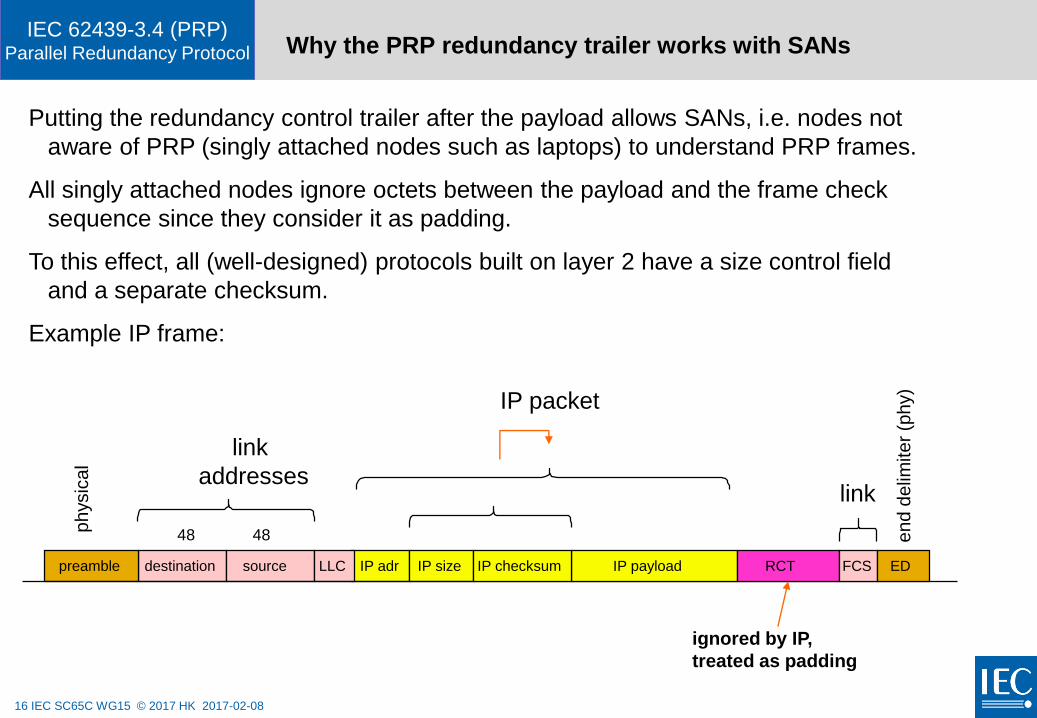
IEC 62439-3.4 (PRP)Parallel Redundancy Protocol Why the PRP redundancy trailer works with SANs
Putting the redundancy control trailer after the payload allows SANs, i.e. nodes not
aware of PRP (singly attached nodes such as laptops) to understand PRP frames.
All singly attached nodes ignore octets between the payload and the frame check
sequence since they consider it as padding.
To this effect, all (well-designed) protocols built on layer 2 have a size control field
and a separate checksum.
Example IP frame:
destination source IP adr IP sizepreamble
ph
ysic
al
link
addresses
LLC IP payload
IP packet
RCT
ignored by IP,
treated as padding
FCS ED
link
en
d d
elim
ite
r (p
hy)
48 48
IP checksum
17 IEC SC65C WG15 © 2017 HK 2017-02-08
IEC 62439-3.4 (PRP)Parallel Redundancy Protocol Sequence number build-up
A PRP node increments the sequence number for each frame (pair) sent.
A PRP receiver uniquely identifies a frame by {MACaddress, SequenceNumber}
Due to bridge filtering, a receiver only receives part of the traffic (especially if one part of
the traffic is multicast) and could see gaps in the received sequence numbers from the
same source.
It is also possible that the same frame comes more than twice in case of reconfiguration
of RSTP.
To this effect, a receiver keeps a list of received frame identifiers and sequence numbers
(as a table, hash table, or numbering scheme).
NOTE: the former version PRP0 had a sequence number per {sourceMAC, destinationMAC} tuple.
18 IEC SC65C WG15 © 2017 HK 2017-02-08
IEC 62439-3.4 (PRP)Parallel Redundancy Protocol Principle of duplicate detection
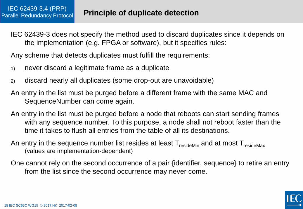
IEC 62439-3 does not specify the method used to discard duplicates since it depends on
the implementation (e.g. FPGA or software), but it specifies rules:
Any scheme that detects duplicates must fulfill the requirements:
1) never discard a legitimate frame as a duplicate
2) discard nearly all duplicates (some drop-out are unavoidable)
An entry in the list must be purged before a different frame with the same MAC and
SequenceNumber can come again.
An entry in the list must be purged before a node that reboots can start sending frames
with any sequence number. To this purpose, a node shall not reboot faster than the
time it takes to flush all entries from the table of all its destinations.
An entry in the sequence number list resides at least TresideMin and at most TresideMax
(values are implementation-dependent)
One cannot rely on the second occurrence of a pair {identifier, sequence} to retire an entry
from the list since the second occurrence may never come.
19 IEC SC65C WG15 © 2017 HK 2017-02-08
IEC 62439-3.4 (PRP)Parallel Redundancy Protocol
Duplicate detection: wrap-around of the sequence
number
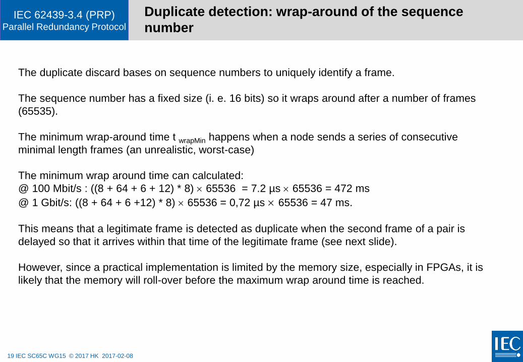
The duplicate discard bases on sequence numbers to uniquely identify a frame.
The sequence number has a fixed size (i. e. 16 bits) so it wraps around after a number of frames
(65535).
The minimum wrap-around time t wrapMin happens when a node sends a series of consecutive
minimal length frames (an unrealistic, worst-case)
The minimum wrap around time can calculated:
@ 100 Mbit/s : ((8 + 64 + 6 + 12) * 8) 65536 = 7.2 µs 65536 = 472 ms
@ 1 Gbit/s: ((8 + 64 + 6 +12) * 8) 65536 = 0,72 µs 65536 = 47 ms.
This means that a legitimate frame is detected as duplicate when the second frame of a pair is
delayed so that it arrives within that time of the legitimate frame (see next slide).
However, since a practical implementation is limited by the memory size, especially in FPGAs, it is
likely that the memory will roll-over before the maximum wrap around time is reached.
20 IEC SC65C WG15 © 2017 HK 2017-02-08
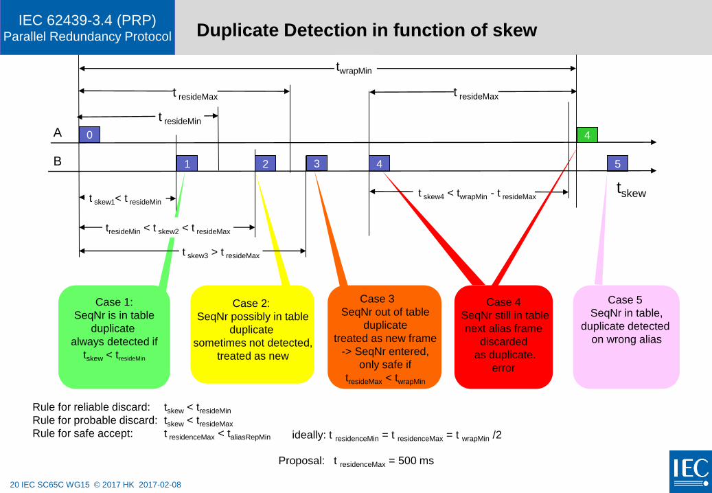
IEC 62439-3.4 (PRP)Parallel Redundancy Protocol Duplicate Detection in function of skew
t skew1< t resideMin
tresideMin < t skew2 < t resideMax
t skew4 < twrapMin - t resideMax
4
t skew3 > t resideMax
Rule for reliable discard: tskew < tresideMin
Rule for probable discard: tskew < tresideMax
Rule for safe accept: t residenceMax < taliasRepMin
Case 1:
SeqNr is in table
duplicate
always detected if
tskew < tresideMin
Case 2:
SeqNr possibly in table
duplicate
sometimes not detected,
treated as new
Case 4
SeqNr still in table
next alias frame
discarded
as duplicate.
error
Case 5
SeqNr in table,
duplicate detected
on wrong alias
A 0
1 42 3 5B
Case 3
SeqNr out of table
duplicate
treated as new frame
-> SeqNr entered,
only safe if
tresideMax < twrapMin
ideally: t residenceMin = t residenceMax = t wrapMin /2
Proposal: t residenceMax = 500 ms
t resideMax
tskew
twrapMin
t resideMax
t resideMin
21 IEC SC65C WG15 © 2017 HK 2017-02-08
IEC 62439-3.4 (PRP)Parallel Redundancy Protocol Discussion
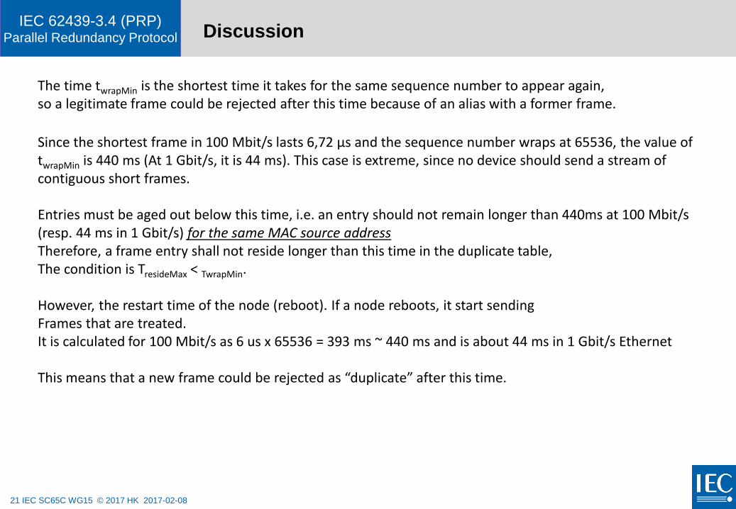
The time twrapMin is the shortest time it takes for the same sequence number to appear again, so a legitimate frame could be rejected after this time because of an alias with a former frame.
Since the shortest frame in 100 Mbit/s lasts 6,72 µs and the sequence number wraps at 65536, the value of twrapMin is 440 ms (At 1 Gbit/s, it is 44 ms). This case is extreme, since no device should send a stream of contiguous short frames.
Entries must be aged out below this time, i.e. an entry should not remain longer than 440ms at 100 Mbit/s (resp. 44 ms in 1 Gbit/s) for the same MAC source addressTherefore, a frame entry shall not reside longer than this time in the duplicate table,The condition is TresideMax < TwrapMin.
However, the restart time of the node (reboot). If a node reboots, it start sending Frames that are treated. It is calculated for 100 Mbit/s as 6 us x 65536 = 393 ms ~ 440 ms and is about 44 ms in 1 Gbit/s Ethernet
This means that a new frame could be rejected as “duplicate” after this time.

22 IEC SC65C WG15 © 2017 HK 2017-02-08
IEC 62439-3.4 (PRP)Parallel Redundancy Protocol
PRP Frame formats
23 IEC SC65C WG15 © 2017 HK 2017-02-08
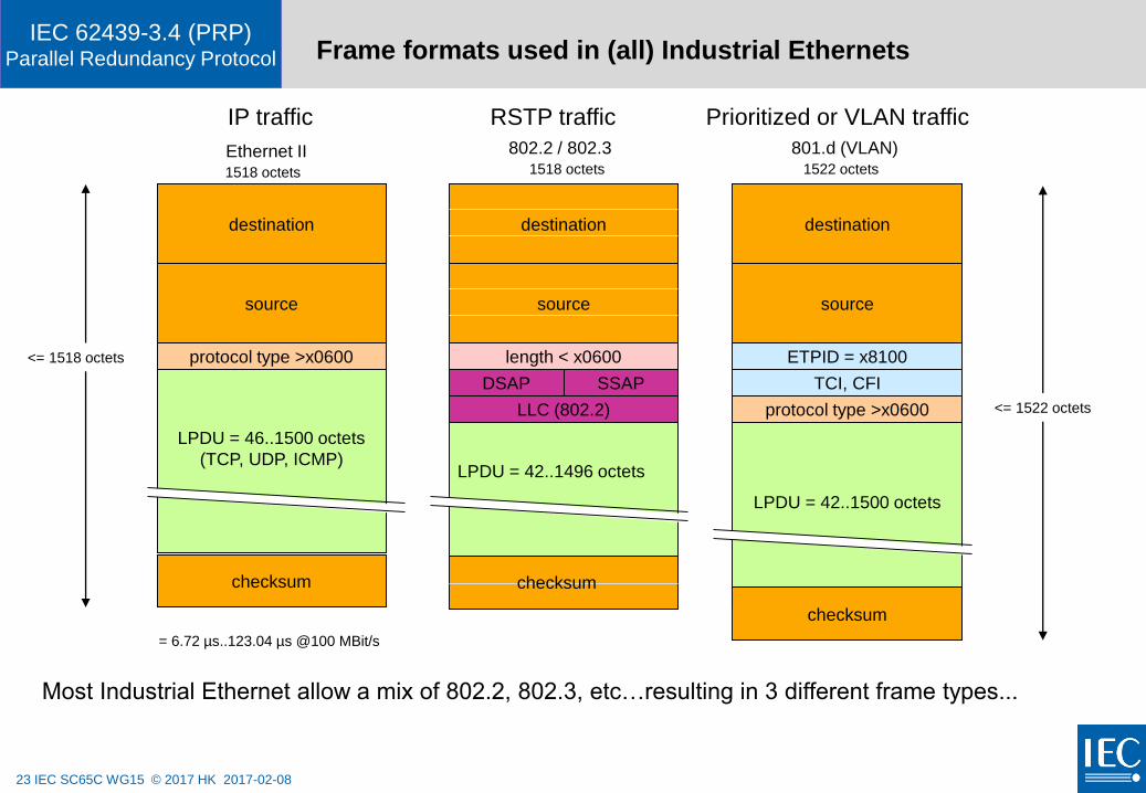
IEC 62439-3.4 (PRP)Parallel Redundancy Protocol Frame formats used in (all) Industrial Ethernets
LPDU = 42..1500 octets
LPDU = 46..1500 octets
(TCP, UDP, ICMP)
length < x0600
destination
source
DSAP
LLC (802.2)
SSAP
protocol type >x0600
destination
source
checksum
destination
source
protocol type
checksum
ETPID = x8100
TCI, CFI
1518 octets 1522 octets
801.d (VLAN)Ethernet II 802.2 / 802.3
Most Industrial Ethernet allow a mix of 802.2, 802.3, etc…resulting in 3 different frame types...
IP traffic RSTP traffic Prioritized or VLAN traffic
checksum
LPDU = 42..1496 octets
protocol type >x0600
1518 octets
= 6.72 µs..123.04 µs @100 MBit/s
<= 1518 octets
<= 1522 octets
24 IEC SC65C WG15 © 2017 HK 2017-02-08
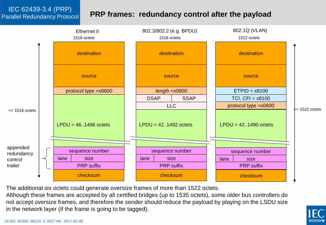
IEC 62439-3.4 (PRP)Parallel Redundancy Protocol PRP frames: redundancy control after the payload
The additional six octets could generate oversize frames of more than 1522 octets.
Although these frames are accepted by all certified bridges (up to 1535 octets), some older bus controllers do
not accept oversize frames, and therefore the sender should reduce the payload by playing on the LSDU size
in the network layer (if the frame is going to be tagged).
length <x0600
destination
source
DSAP
LLC
SSAP
protocol type >x0600
destination
source
destination
source
protocol type
checksum
ETPID = x8100
TCI, CFI = x8100
1522 octets
802.1Q (VLAN)802.3/802.2 (e.g. BPDU)Ethernet II
sequence number
checksum
sequence number
checksum
sequence number
sizelane sizelane sizelane
appended
redundancy
control
trailer
<= 1518 octets <= 1522 octets
protocol type >x0600
protocol type >x0600
LPDU = 42..1490 octetsLPDU = 42..1492 octetsLPDU = 46..1496 octets
1518 octets1518 octets
PRP suffixPRP suffixPRP suffix
25 IEC SC65C WG15 © 2017 HK 2017-02-08
IEC 62439-3.4 (PRP)Parallel Redundancy Protocol Is appending a redundancy trailer in line with IEEE 802.3 ?
PRP’s Duplicate Discard mode requires that frames be stretched by 6 octets.
All protocols must be able to deal with data in the frames after the payload,
since padding is part of the Ethernet protocol.
E.g. IP has its own size control and checksum – data after the IP payload are ignored.
The maximum size of the payload must be reduced by six octets to match the size of 1500
octets foreseen by IEEE 802.3-2002 § 4.4.2.1
This would not be necessary for the bridges, since all commercial bridges permit longer frames
to support double VLAN tagging (Q-in-Q).
However, some older Network Interfaces for PCs do not accept longer frames.
Network analyzers can deal with PRP, the corresponding PRP extension already has been
appended to EtherReal (http://www.ethereal.com) / Wireshark
In networks where this could become a problem, the source should reduce of the LSDU size,
e.g. at the IP level.
26 IEC SC65C WG15 © 2017 HK 2017-02-08
IEC 62439-3.4 (PRP)Parallel Redundancy Protocol
PRP
suffix
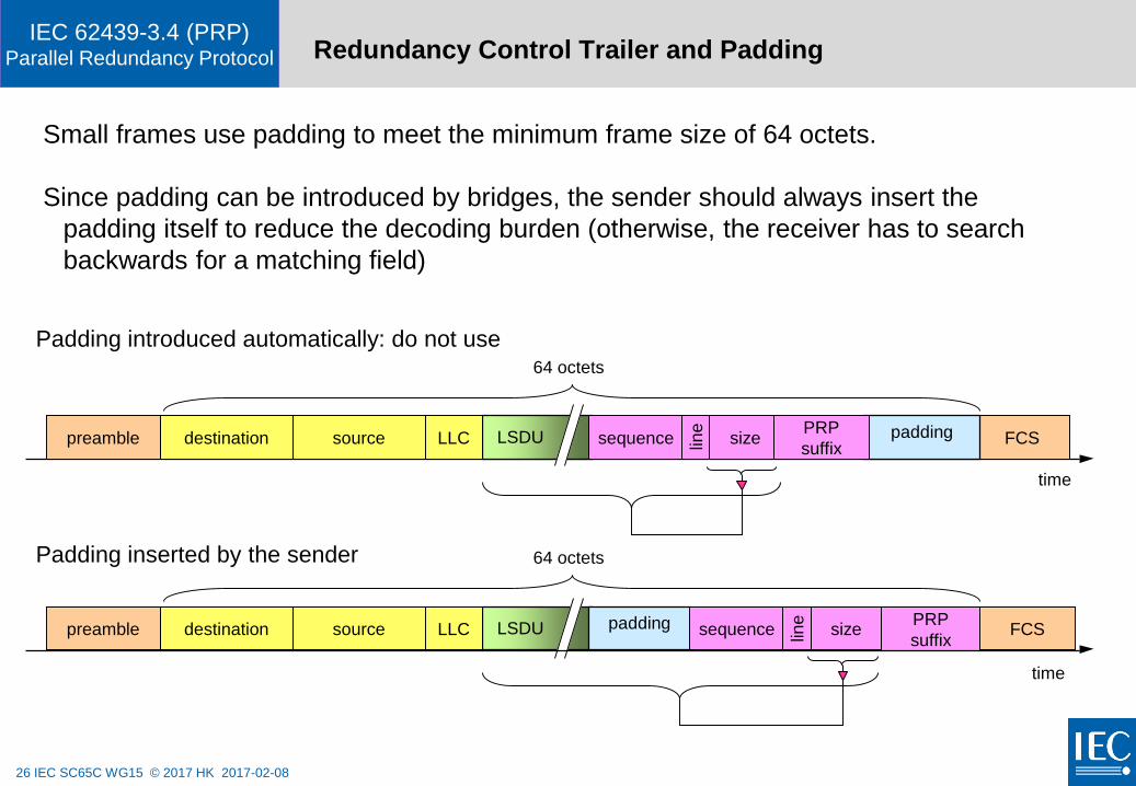
Redundancy Control Trailer and Padding
time
destination source LLC FCSLSDUpreamble paddingsizesequence line
Small frames use padding to meet the minimum frame size of 64 octets.
Since padding can be introduced by bridges, the sender should always insert the
padding itself to reduce the decoding burden (otherwise, the receiver has to search
backwards for a matching field)
64 octets
time
destination source LLC FCSLSDUpreamble padding sizesequence line
64 octetsPadding inserted by the sender
Padding introduced automatically: do not use
PRP
suffix
27 IEC SC65C WG15 © 2017 HK 2017-02-08
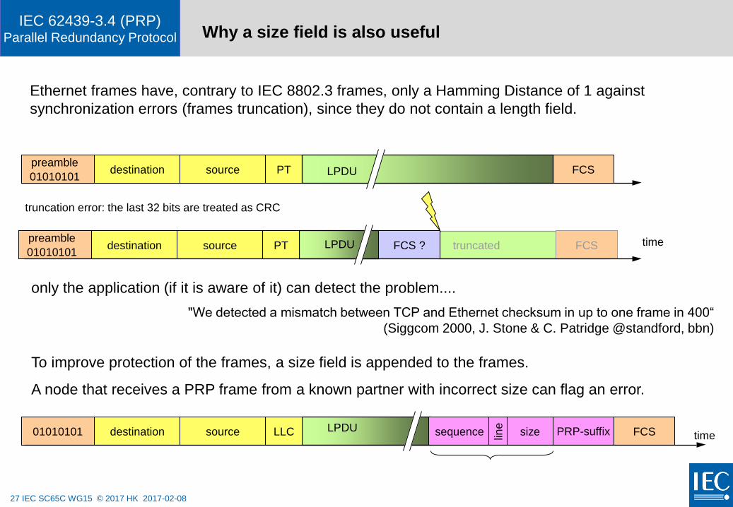
IEC 62439-3.4 (PRP)Parallel Redundancy Protocol Why a size field is also useful
time
timetruncateddestination source PT LPDU FCS ?
destination source LLC FCSLPDU01010101 sizesequence
destination source PT FCSLPDULPDU
truncation error: the last 32 bits are treated as CRC
preamble
Ethernet frames have, contrary to IEC 8802.3 frames, only a Hamming Distance of 1 against
synchronization errors (frames truncation), since they do not contain a length field.
To improve protection of the frames, a size field is appended to the frames.
A node that receives a PRP frame from a known partner with incorrect size can flag an error.
01010101
preamble
01010101FCS
line
only the application (if it is aware of it) can detect the problem....
"We detected a mismatch between TCP and Ethernet checksum in up to one frame in 400“
(Siggcom 2000, J. Stone & C. Patridge @standford, bbn)
PRP-suffix
28 IEC SC65C WG15 © 2017 HK 2017-02-08
IEC 62439-3.4 (PRP)Parallel Redundancy Protocol
PRP network management

29 IEC SC65C WG15 © 2017 HK 2017-02-08
IEC 62439-3.4 (PRP)Parallel Redundancy Protocol Network supervision and detection of lurking faults
PRP checks continuously all paths.
In order not to rely on application cyclic data for this, each DANP sends periodically a supervision
frame that indicates its state.
The period is relatively long (some seconds) since the supervision frame is not needed for
switchover, but only to check dormant redundancy.
All nodes keep a node table of all detected partners and registers the last time a node
was seen as well as the number of received frames from each other node over both interfaces.
The duplicate discard mode allows to keep track of all nodes in the network.
Changes to the topology are communicated over SNMP or to the Link Management Entity.
30 IEC SC65C WG15 © 2017 HK 2017-02-08
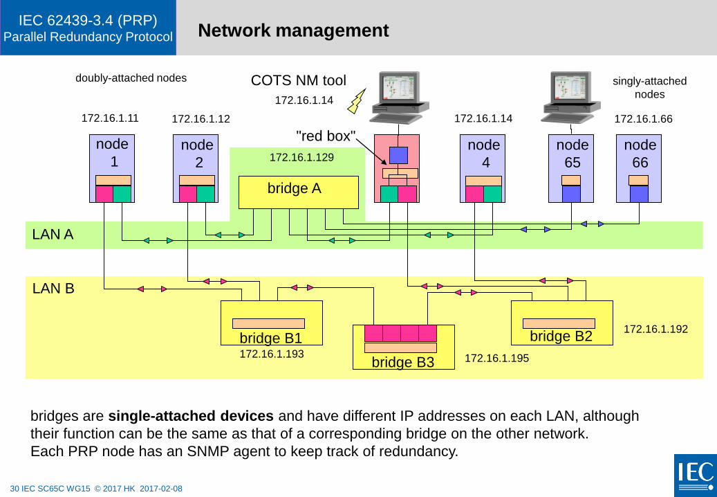
IEC 62439-3.4 (PRP)Parallel Redundancy Protocol Network management
singly-attached
nodes
172.16.1.14 172.16.1.66
node
1node
2
node
4
node
65
node
66
bridge A
"red box"
LAN A
LAN B
bridge B2
172.16.1.11 172.16.1.12
172.16.1.129
172.16.1.192
doubly-attached nodes
bridge B3 172.16.1.195
COTS NM tool
172.16.1.14
bridge B1172.16.1.193
bridges are single-attached devices and have different IP addresses on each LAN, although
their function can be the same as that of a corresponding bridge on the other network.
Each PRP node has an SNMP agent to keep track of redundancy.

31 IEC SC65C WG15 © 2017 HK 2017-02-08
IEC 62439-3.4 (PRP)Parallel Redundancy Protocol
PRP technology
32 IEC SC65C WG15 © 2017 HK 2017-02-08
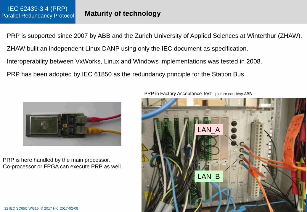
IEC 62439-3.4 (PRP)Parallel Redundancy Protocol Maturity of technology
PRP is supported since 2007 by ABB and the Zurich University of Applied Sciences at Winterthur (ZHAW).
ZHAW built an independent Linux DANP using only the IEC document as specification.
Interoperability between VxWorks, Linux and Windows implementations was tested in 2008.
PRP has been adopted by IEC 61850 as the redundancy principle for the Station Bus.
LAN_A
LAN_B
PRP is here handled by the main processor.
Co-processor or FPGA can execute PRP as well.
PRP in Factory Acceptance Test - picture courtesy ABB
33 IEC SC65C WG15 © 2017 HK 2017-02-08
IEC 62439-3.4 (PRP)Parallel Redundancy Protocol PRP: Pros & Cons
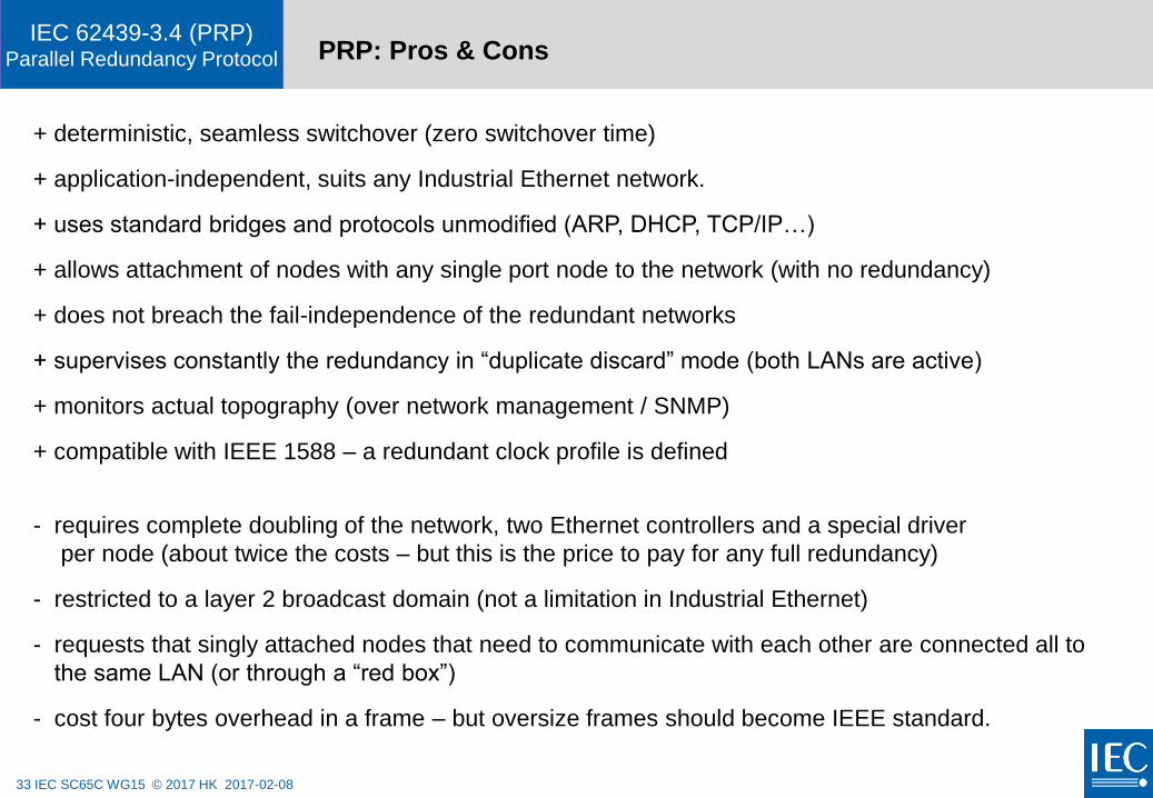
+ deterministic, seamless switchover (zero switchover time)
+ application-independent, suits any Industrial Ethernet network.
+ uses standard bridges and protocols unmodified (ARP, DHCP, TCP/IP…)
+ allows attachment of nodes with any single port node to the network (with no redundancy)
+ does not breach the fail-independence of the redundant networks
+ supervises constantly the redundancy in “duplicate discard” mode (both LANs are active)
+ monitors actual topography (over network management / SNMP)
+ compatible with IEEE 1588 – a redundant clock profile is defined
- requires complete doubling of the network, two Ethernet controllers and a special driver
per node (about twice the costs – but this is the price to pay for any full redundancy)
- restricted to a layer 2 broadcast domain (not a limitation in Industrial Ethernet)
- requests that singly attached nodes that need to communicate with each other are connected all to
the same LAN (or through a “red box”)
- cost four bytes overhead in a frame – but oversize frames should become IEEE standard.

34 IEC SC65C WG15 © 2017 HK 2017-02-08
IEC 62439-3.4 (PRP)Parallel Redundancy Protocol
PRP vs. other standards
35 IEC SC65C WG15 © 2017 HK 2017-02-08
IEC 62439-3.4 (PRP)Parallel Redundancy Protocol State of standardization and other solutions
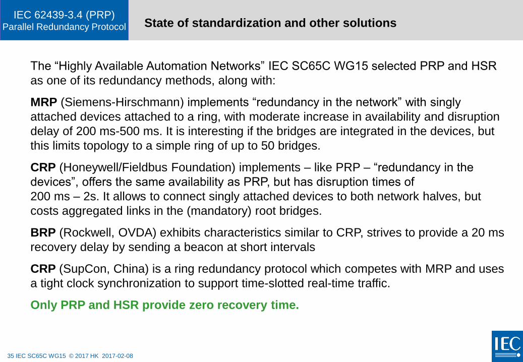
The “Highly Available Automation Networks” IEC SC65C WG15 selected PRP and HSR
as one of its redundancy methods, along with:
MRP (Siemens-Hirschmann) implements “redundancy in the network” with singly
attached devices attached to a ring, with moderate increase in availability and disruption
delay of 200 ms-500 ms. It is interesting if the bridges are integrated in the devices, but
this limits topology to a simple ring of up to 50 bridges.
CRP (Honeywell/Fieldbus Foundation) implements – like PRP – “redundancy in the
devices”, offers the same availability as PRP, but has disruption times of
200 ms – 2s. It allows to connect singly attached devices to both network halves, but
costs aggregated links in the (mandatory) root bridges.
BRP (Rockwell, OVDA) exhibits characteristics similar to CRP, strives to provide a 20 ms
recovery delay by sending a beacon at short intervals
CRP (SupCon, China) is a ring redundancy protocol which competes with MRP and uses
a tight clock synchronization to support time-slotted real-time traffic.
Only PRP and HSR provide zero recovery time.
36 IEC SC65C WG15 © 2017 HK 2017-02-08
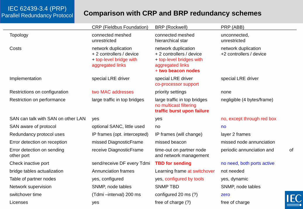
IEC 62439-3.4 (PRP)Parallel Redundancy Protocol Comparison with CRP and BRP redundancy schemes
CRP (Fieldbus Foundation) BRP (Rockwell) PRP (ABB)
Topology connected meshed connected meshed unconnected,
unrestricted hierarchical star unrestricted
Costs network duplication network duplication network duplication
+ 2 controllers / device + 2 controllers / device +2 controllers / device
+ top-level bridge with + top-level bridges with
aggregated links aggregated links
+ two beacon nodes
Implementation special LRE driver special LRE driver special LRE driver
co-processor support
Restrictions on configuration two MAC addresses priority settings none
Restriction on performance large traffic in top bridges large traffic in top bridges negligible (4 bytes/frame)
no multicast filtering
traffic burst upon failure
SAN can talk with SAN on other LAN yes yes no, except through red box
SAN aware of protocol optional SANC, little used no no
Redundancy protocol uses IP frames (opt. intercepted) IP frames (will change) layer 2 frames
Error detection on reception missed DiagnosticFrame missed beacon missed node annunciation
Error detection on sending receive DiagnosticFrame time-out on partner node periodic annunciation and of
other port and network management
Check inactive port send/receive DF every Tdmi TBD for sending no need, both ports active
bridge tables actualization Annunciation frames Learning frame at switchover not needed
Table of partner nodes yes, configured yes, configured by tools yes, dynamic
Network supervision SNMP, node tables SNMP TBD SNMP, node tables
switchover time (Tdmi –interval) 200 ms configured 20 ms (?) zero
Licenses yes free of charge (?) free of charge

INTERNATIONAL
ELECTROTECHNICAL
COMMISSION