ideal™ 1000 manual - ageecreative operating manual.pdfdetermine where on a concrete slab the ideal...
TRANSCRIPT

Ideal™ 1000 Manual20016-6111

1
Contents1. Introduction. . . . . . . . . . . . . . . . . . . . . . . . . . . . . . . . . . . . . . . . . . . . . . . . . . . . . . . . . . . . . . . . . . . . 2
1.0 Introduction. . . . . . . . . . . . . . . . . . . . . . . . . . . . . . . . . . . . . . . . . . . . . . . . . . . . . . . . . . . . . . . . 21.1 SafetyGuidelines. . . . . . . . . . . . . . . . . . . . . . . . . . . . . . . . . . . . . . . . . . . . . . . . . . . . . . . . . . . 21.2 PrinciplesofSharpening. . . . . . . . . . . . . . . . . . . . . . . . . . . . . . . . . . . . . . . . . . . . . . . . . . . . . . 31.3 EdgeShape . . . . . . . . . . . . . . . . . . . . . . . . . . . . . . . . . . . . . . . . . . . . . . . . . . . . . . . . . . . . . . . 41.4 ReelShape. . . . . . . . . . . . . . . . . . . . . . . . . . . . . . . . . . . . . . . . . . . . . . . . . . . . . . . . . . . . . . . . 4
2. SetUp. . . . . . . . . . . . . . . . . . . . . . . . . . . . . . . . . . . . . . . . . . . . . . . . . . . . . . . . . . . . . . . . . . . . . . . . 52.0 LocatingYourGrinder. . . . . . . . . . . . . . . . . . . . . . . . . . . . . . . . . . . . . . . . . . . . . . . . . . . . . . . . 52.1 UnpackingtheGrinder. . . . . . . . . . . . . . . . . . . . . . . . . . . . . . . . . . . . . . . . . . . . . . . . . . . . . . . 52.3 Connectingtheservice. . . . . . . . . . . . . . . . . . . . . . . . . . . . . . . . . . . . . . . . . . . . . . . . . . . . . . . 6
3. PreparingtoGrind. . . . . . . . . . . . . . . . . . . . . . . . . . . . . . . . . . . . . . . . . . . . . . . . . . . . . . . . . . . . . . . 73.0 Preparingthereelmowerforgrinding . . . . . . . . . . . . . . . . . . . . . . . . . . . . . . . . . . . . . . . . . . . 73.1 ControlPanel . . . . . . . . . . . . . . . . . . . . . . . . . . . . . . . . . . . . . . . . . . . . . . . . . . . . . . . . . . . . . . 73.2 Settingthereliefangle . . . . . . . . . . . . . . . . . . . . . . . . . . . . . . . . . . . . . . . . . . . . . . . . . . . . . . . 93.3 Carriagetravel . . . . . . . . . . . . . . . . . . . . . . . . . . . . . . . . . . . . . . . . . . . . . . . . . . . . . . . . . . . . 103.4 PositiontheFence . . . . . . . . . . . . . . . . . . . . . . . . . . . . . . . . . . . . . . . . . . . . . . . . . . . . . . . . . 103.5 Adjustingthebedkniferearstop . . . . . . . . . . . . . . . . . . . . . . . . . . . . . . . . . . . . . . . . . . . . . . 123.6Clampingbedknife. . . . . . . . . . . . . . . . . . . . . . . . . . . . . . . . . . . . . . . . . . . . . . . . . . . . . . . . . . 133.7 Adjustingthefrontfacecontact . . . . . . . . . . . . . . . . . . . . . . . . . . . . . . . . . . . . . . . . . . . . . . . 143.8 Checkingcontact . . . . . . . . . . . . . . . . . . . . . . . . . . . . . . . . . . . . . . . . . . . . . . . . . . . . . . . . . . 16
4. Grinding. . . . . . . . . . . . . . . . . . . . . . . . . . . . . . . . . . . . . . . . . . . . . . . . . . . . . . . . . . . . . . . . . . . . . . 174.0 GrindingtheBedKnife.. . . . . . . . . . . . . . . . . . . . . . . . . . . . . . . . . . . . . . . . . . . . . . . . . . . . . . 174.1 Dressingthegrindingstone . . . . . . . . . . . . . . . . . . . . . . . . . . . . . . . . . . . . . . . . . . . . . . . . . . 19
5. Maintenance . . . . . . . . . . . . . . . . . . . . . . . . . . . . . . . . . . . . . . . . . . . . . . . . . . . . . . . . . . . . . . . . . . 205.0 Generalmaintenance. . . . . . . . . . . . . . . . . . . . . . . . . . . . . . . . . . . . . . . . . . . . . . . . . . . . . . . 205.1 Adjustingthecarriagebearings . . . . . . . . . . . . . . . . . . . . . . . . . . . . . . . . . . . . . . . . . . . . . . . 215.2 Mountinggrindingwheels. . . . . . . . . . . . . . . . . . . . . . . . . . . . . . . . . . . . . . . . . . . . . . . . . . . . 225.3 Adjustingthegibs. . . . . . . . . . . . . . . . . . . . . . . . . . . . . . . . . . . . . . . . . . . . . . . . . . . . . . . . . . 23

2
1. IntroductIon
1.0 IntroductionThankyouforselectingtheSimplex•Ideal•PeerlessReel Mower Grinder. The Peerless 2000 Grinderisdesignedandbuiltfromtopqualitymaterialsandcomponentsbypeoplewhocare,anditwillgiveyoudecadesofservice.
Please takea fewminutes to registeryourgrinderonourwebsitewww.sipgrinder.comsothatwecanprovideyoubetterserviceandsupport.
1.1 SafetyGuidelinesThefollowingaregeneralsafetyguidelines.Pleaseread and understand these guidelines before pro-ceeding.Asisthecasewithmostmachinery,failuretooperateitinasafemannermayresultindamage,injuryorlossoflife.Pleasebecareful.
Alwayscloseshieldorwearsafetyglassesandfaceshieldwhengrinding!
Keepallguardsinplaceandfunctioning.
Donotwearanylooseclothingorjewelrywhichmaygetcaughtinthemachinery.Securelonghair.
Keepyourworkareacleanandorganized.
Setuptheworkproperly,usingthecorrecttoolsand fixtures. Ensure that work is securely clamped.
Use thewrenchesprovidedwhenchanging thegrindingwheelandalwaysensurethatnut is tight.Donotovertighteningasthatmaydamagethegrind-ingwheel.
Alwaysreplacedamagedgrindingwheel.
Neverleavegrinderrunningwhileunattended.
Inadditiontothesafetyguidelinesjustlisted,therearesafetynoticesthroughoutthismanualwhicharedenotedasfollows:
AnInformationNoticeprovidesinformationoracau-tionwhereminordamagemayoccur.
Running the spin motor too fast may damage the indexer.
AWarningNotice indicatesasituationwhichcouldcauseseveredamage,seriousinjuryordeath.
Always close shield or wear safety glasses and face shield when grinding.
ADangerNoticeindicatesaverydangeroussituationwhichifcontinuedwillcauseseveredamage,seriousinjuryordeath.
Do not overtighten the nut as it will cause the grinding wheel to explode!
Again,makesurethatyoureadandunderstandthesewarningsbeforeproceedingbecausefailuretooper-ateanymachinery inasafemannermay result indamage,injuryorlossoflife.
1.
2.
3.
4.
5.
6.
7.
8.
3
1.2 PrinciplesofSharpeningThereeltypelawnmowercutsgrassusingtheprin-ciplesofshears.Itisnecessary,therefore,tohavetwosharpcuttingedgesmakingcloseenoughcontacttocutthegrasscleanly.Thisistheleastharmfulmethodofmowinggrass,becauseeachbladeofgrassissup-portedbythebedknifewhilethereelbladeshearsitoff.Thiseliminatesbleedingandbrowntopswhichoccurwhenthegrassiswhippedoffwithrotarytypemowers.
On a five bladed reel mower, the bed knife does five timestheworkofanyonereelbladeasallthereelbladesmustshearagainstit.Thebedknife,therefore,isthemastercuttingelementandalthoughmadeofheavierandhardersteels,itisimpossibletoproperlysharpenamowerwithdullreelbladeswithoutsharp-eningthebedknifetoo.
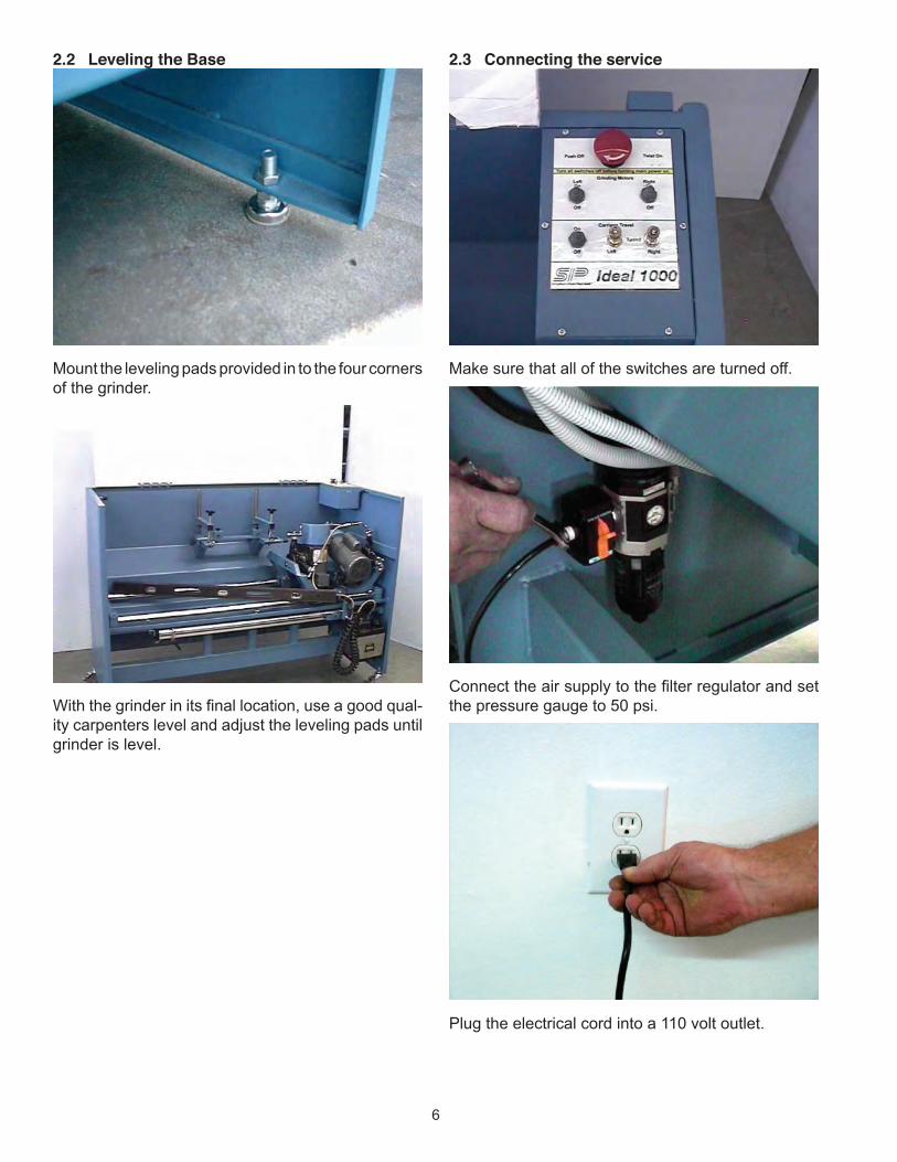
Rake Angle
Rotation
Relief Angle
Land Area
The figure above shows the different features of the reelmowerblades.ThereelbladeRelief Angle servesreducesthecontactareabetweenthereelandthebedknife.Itiscreatedbyindividuallyreliefgrindingeachreelblade.TheLand Area indicateshowmuchof thereelblade iscontactingthebedknifeand iscreatedduringspingrinding.TheRake Angle issetbytheslotinthespiderandensuresthatthecuttingedge is the first part of the blade to touch the grass blade.Itcannotbechanged.
Front Face Angle
Top Face Angle
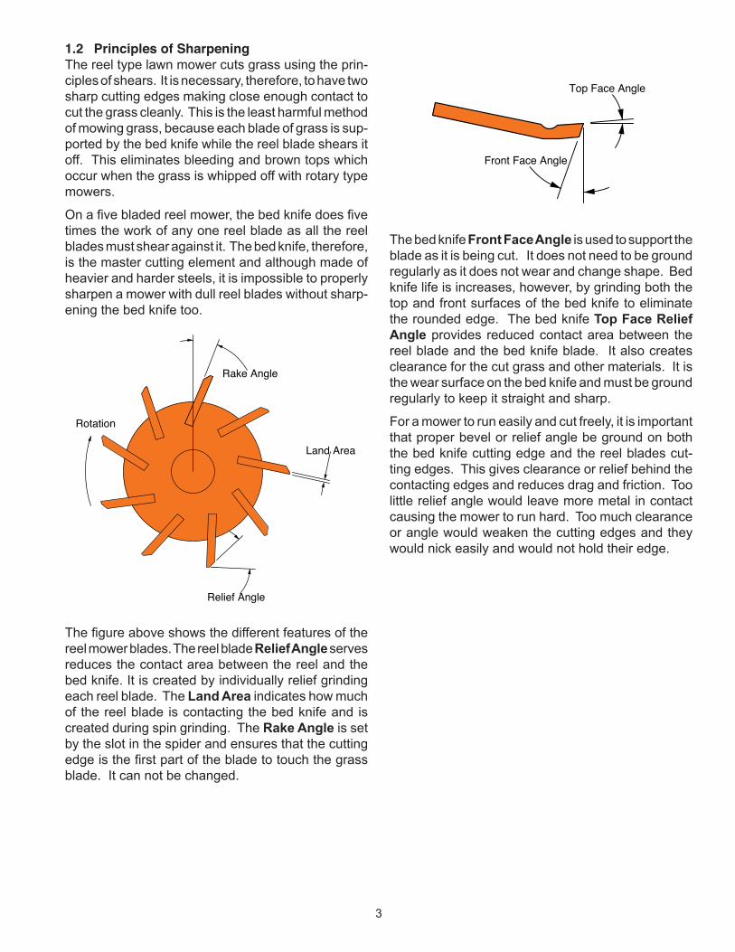
ThebedknifeFront Face Angle isusedtosupportthebladeasitisbeingcut.Itdoesnotneedtobegroundregularlyasitdoesnotwearandchangeshape.Bedknifelifeisincreases,however,bygrindingboththetopandfrontsurfacesofthebedknifetoeliminatetheroundededge.ThebedknifeTop Face Relief Angle provides reducedcontactareabetween thereelbladeandthebedknifeblade.Italsocreatesclearanceforthecutgrassandothermaterials.Itisthewearsurfaceonthebedknifeandmustbegroundregularlytokeepitstraightandsharp.
Foramowertoruneasilyandcutfreely,itisimportantthatproperbevelorreliefanglebegroundonboththebedknifecuttingedgeandthereelbladescut-tingedges.Thisgivesclearanceorreliefbehindthecontactingedgesandreducesdragandfriction.Toolittlereliefanglewouldleavemoremetalincontactcausingthemowertorunhard.Toomuchclearanceoranglewouldweakenthecuttingedgesandtheywouldnickeasilyandwouldnotholdtheiredge.

4
1.3 EdgeShape
Ifthemowerisnotcuttingthegrasscleanly,thecutendofthegrassbladewillappeartornandragged.Whenamowerisbroughtinforservicing,itisimportanttodeterminewhyitisnotcuttingproperly.Often,ifthemowerisoperatingsatisfactorilyineveryrespectexceptcuttingthegrasscleanly,itmayonlyneedanadjustmentofthebedknifetothereelblades.Ex-aminationofthecuttingedgesandshearingcorneronthereelbladesandbedknifeshoulddetermineifthemowerneedsacompletegrindingjob.Often,properlyadjustingthebedknifeisallthatisrequired.Grindingthereelisnecessaryifanyofthefollowingconditionsexist:
1. Significantly rounded blade edges.
2. Bentornickedreelbladeswhichcausestreakingorirregularcontactbetweenreelblades.
3. Unevenbladewear.
4. Significantly cone shaped.
5. Whenallormostofthereliefiswornaway.
1.4 ReelShapeTheprocessofsharpeninga lawnmower is reallyoneof reshaping thecuttingedgeof thebedknifeandthereelbladesbygrinding,torestoretheirabil-itytocutgrass.Equallyimportantistherestorationof the match, or fit, of the reel blades to the cutting edgeofthebedknife,againstwhichallreelbladesshearorcut.Itisalsoimportantthatthebedknifebladeandthebottomofthereelbladesareparalleltothebottomoftherollersandtherollersareparalleltoeachother.Itisdesirableforthereeltohavelittleornoconeshape.Thismakesforamoreevencutandminimizesridgesandlinesinthecutandgougesintheturf
Throughnormalwearorimpropergrindingthereelwillbecomeconeshaped.
Conventionalwisdomsaidthatwhenyougrindareel,itshouldbegroundintoatruecylinder.Thisistrueifboththefrontandrearrollersareadjustable.Ifoneof the rollers is fixed and not parallel to the reel shaft, acylindricalreelwillresultinanunevencut.Thisiswhyitisimportanttoalwaysgrindthebottomofthereelparalleltothebottomoftherollers.
Itisalsoimportantthattherollersareparalleltoeachother.Iftheyarenot,thereelwillrockandgiveanunevencutorgougetheturf.
OnlythePeerless2000isdesignedtogrindthereelsparalleltotherollersandmakeiteasytoparalleltherollerstoeachother.

5
2. Setup
2.0 LocatingYourGrinder
DeterminewhereonaconcreteslabtheIdeal1000willbelocated.
The Ideal1000 requiresstandard110volt, 60Hz,single phase service. Foreign versions with 200volt,50Hz,singlephaseareavailable.Thegrindercomeswithan8footgroundedcordfor110voltser-vice.Thegrinderalsorequiresabout70psicleancompressedair.
2.1 UnpackingtheGrinder
Whileunpacking,examinecarefullyforanyshippingdamage.Anydamageshouldbereportedimmediatelytothecarrier.
Bynowyouhaveremovedtheplasticwrapfromthemaincrate. Afterremovingtheboxofaccessoriesandanyotheroptionalequipment,unboltthegrinderfromthepalletandplaceitinthelocationyouhaveselected.
6
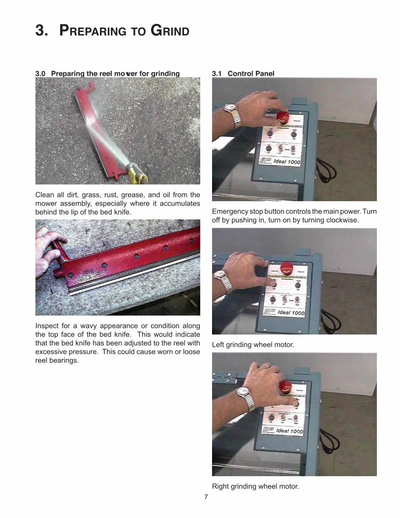
2.2 LevelingtheBase
Mountthelevelingpadsprovidedintothefourcornersofthegrinder.
With the grinder in its final location, use a good qual-itycarpenterslevelandadjustthelevelingpadsuntilgrinderislevel.
2.3 Connectingtheservice
Makesurethatalloftheswitchesareturnedoff.
Connect the air supply to the filter regulator and set thepressuregaugeto50psi.
Plugtheelectricalcordintoa110voltoutlet.
7
3. preparIngtogrInd
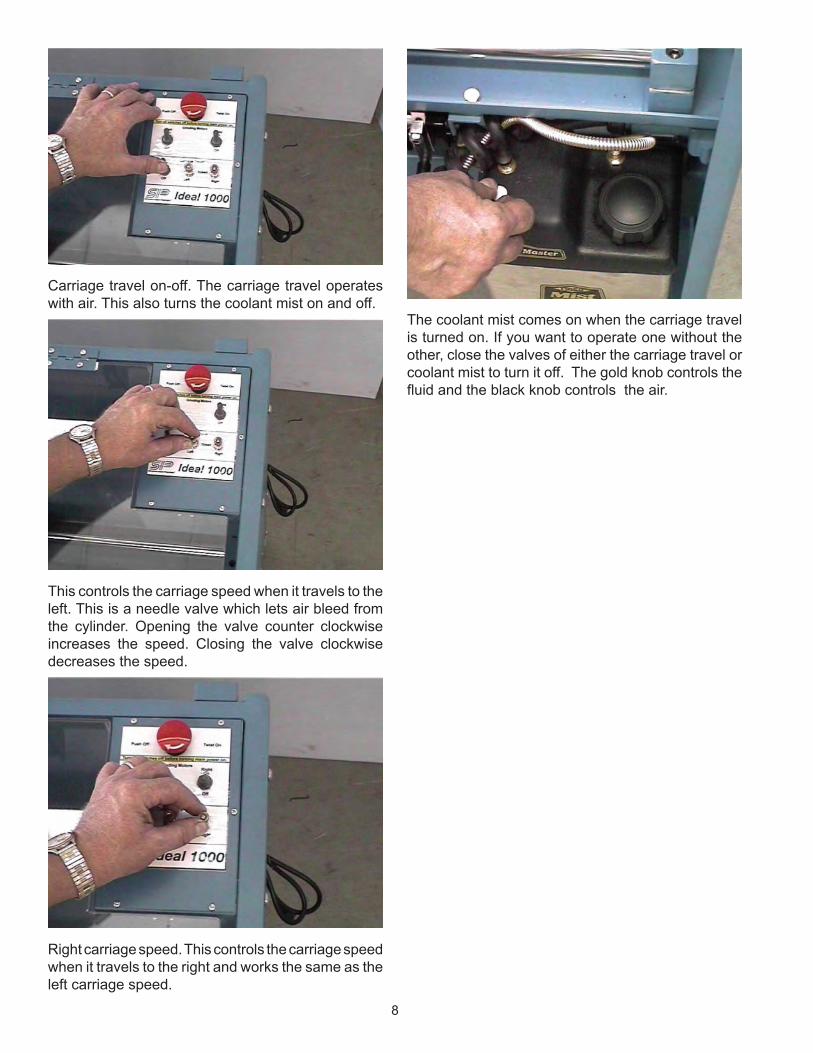
3.0 Preparingthereelmowerforgrinding
Cleanalldirt,grass, rust,grease,andoil from themower assembly, especially where it accumulatesbehindthelipofthebedknife.
Inspect for a wavy appearance or condition alongthe top faceof thebedknife. Thiswould indicatethatthebedknifehasbeenadjustedtothereelwithexcessivepressure.Thiscouldcausewornorloosereelbearings.
3.1 ControlPanel
Emergencystopbuttoncontrolsthemainpower.Turnoffbypushingin,turnonbyturningclockwise.
Leftgrindingwheelmotor.
Rightgrindingwheelmotor.
8
Carriagetravelon-off.Thecarriagetraveloperateswithair.Thisalsoturnsthecoolantmistonandoff.
Thiscontrolsthecarriagespeedwhenittravelstotheleft.Thisisaneedlevalvewhichletsairbleedfromthe cylinder. Opening the valve counter clockwiseincreases the speed. Closing the valve clockwisedecreasesthespeed.
Rightcarriagespeed.Thiscontrolsthecarriagespeedwhenittravelstotherightandworksthesameastheleftcarriagespeed.
Thecoolantmistcomesonwhenthecarriagetravelisturnedon.Ifyouwanttooperateonewithouttheother,closethevalvesofeitherthecarriagetravelorcoolantmisttoturnitoff.Thegoldknobcontrolsthefluid and the black knob controls the air.
9
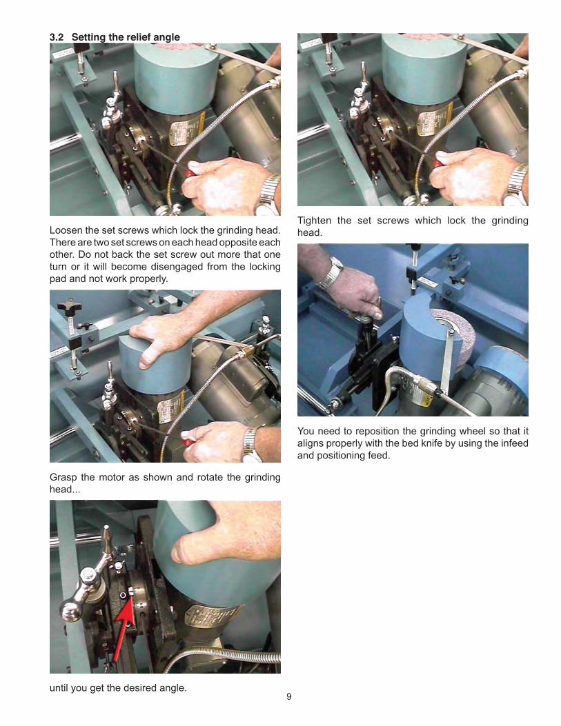
3.2 Settingthereliefangle
Loosenthesetscrewswhichlockthegrindinghead.Therearetwosetscrewsoneachheadoppositeeachother.Donotbackthesetscrewoutmorethatoneturnor itwillbecomedisengaged from the lockingpadandnotworkproperly.
Grasp themotorasshownand rotate thegrindinghead...
untilyougetthedesiredangle.
Tighten the set screws which lock the grindinghead.
Youneedtorepositionthegrindingwheelsothatitalignsproperlywiththebedknifebyusingtheinfeedandpositioningfeed.

10
3.3 Carriagetravel
The carriage may be disengaged from the drivecylinderforeasiersetupbypullingandturningthelatchpin.Toreengagethedrivecylinder,turnthelatchpinuntilitdropsinitsgroove,whenthecylinderandheadarelinedup,thepinwillautomaticallysnapintothecylinder.
The travel stops are set by loosening the lockingscrew,positioningthestopandretigheningthelock-ingscrew.
3.4 PositiontheFence
Unlocktheleftknob
Unclamptherightclamp.
Placethebedknifeonthethreesupportballs.
11
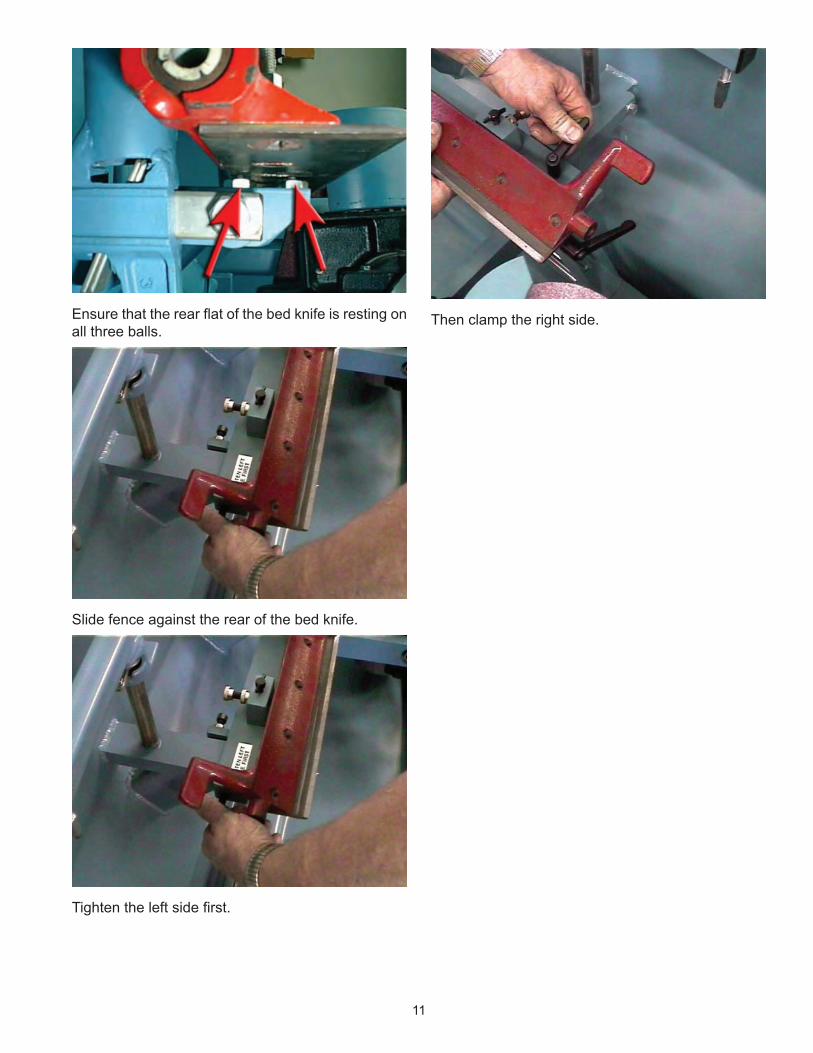
Ensure that the rear flat of the bed knife is resting on allthreeballs.
Slidefenceagainsttherearofthebedknife.
Tighten the left side first.
Thenclamptherightside.

12
3.5 Adjustingthebedkniferearstop
If the rear stops do not firmly contact the bed knife, theycanbeadjusted.
Loosent-knob.
Rotate the cam which holds the rear stop until it firmly contactsthebedknife.
Tightenthet-knob.Repeatforotherstop.
13
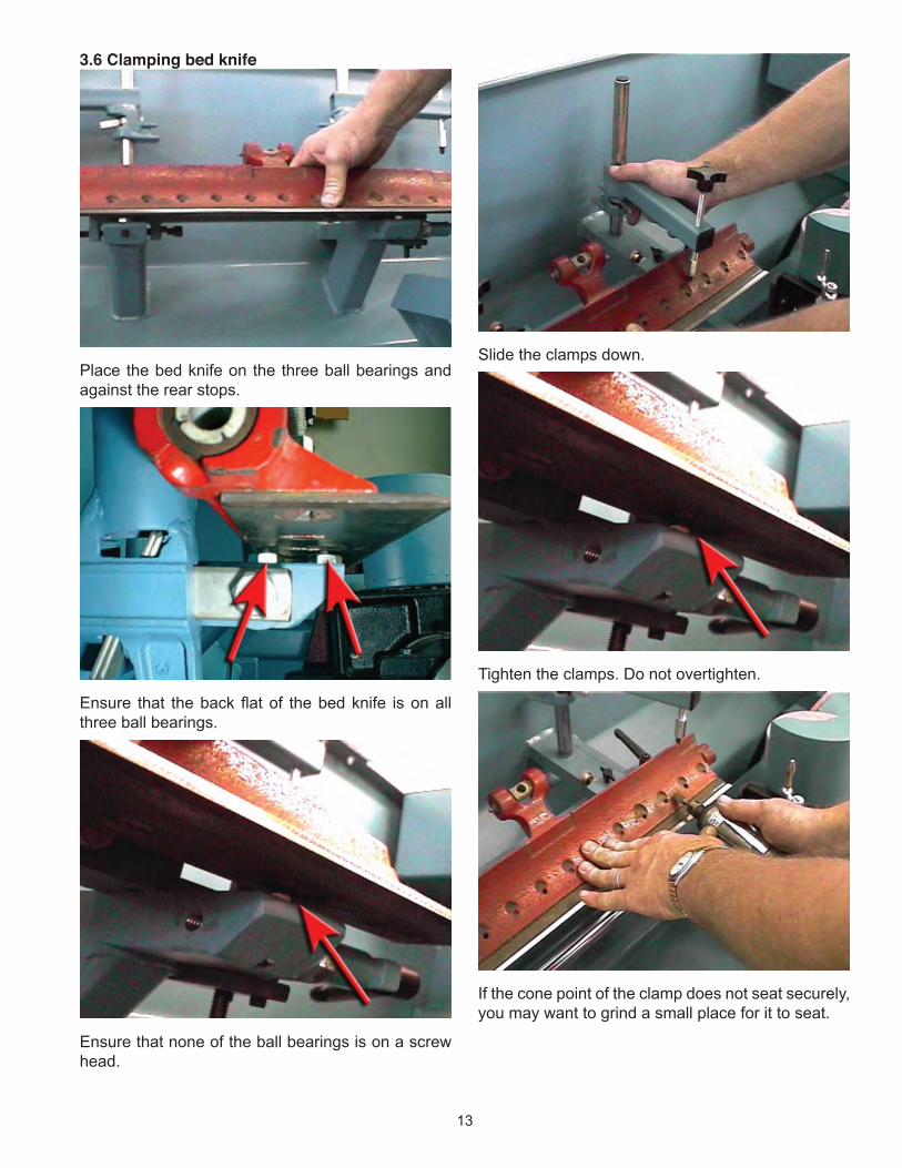
3.6Clampingbedknife
Placethebedknifeonthethreeballbearingsandagainsttherearstops.
Ensure that the back flat of the bed knife is on all threeballbearings.
Ensurethatnoneoftheballbearingsisonascrewhead.
Slidetheclampsdown.
Tightentheclamps.Donotovertighten.
Iftheconepointoftheclampdoesnotseatsecurely,youmaywanttogrindasmallplaceforittoseat.
14
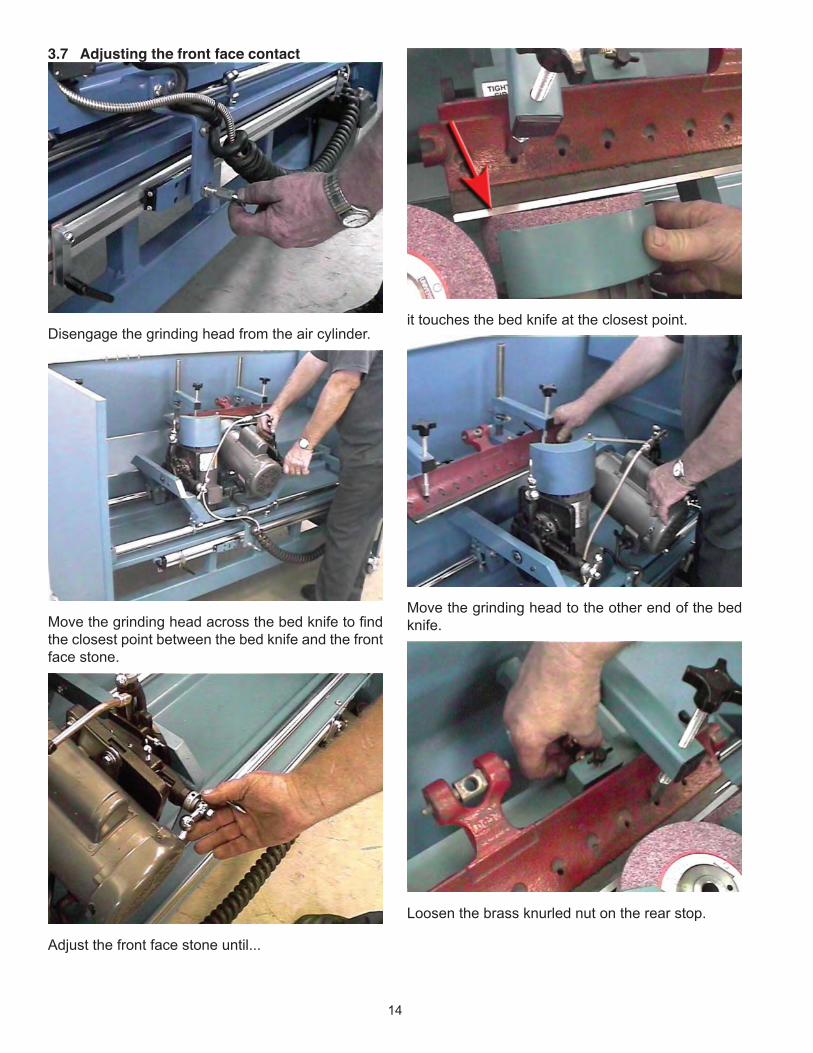
3.7 Adjustingthefrontfacecontact
Disengagethegrindingheadfromtheaircylinder.
Move the grinding head across the bed knife to find theclosestpointbetweenthebedknifeandthefrontfacestone.
Adjustthefrontfacestoneuntil...
ittouchesthebedknifeattheclosestpoint.
Movethegrindingheadtotheotherendofthebedknife.
Loosenthebrassknurlednutontherearstop.
15
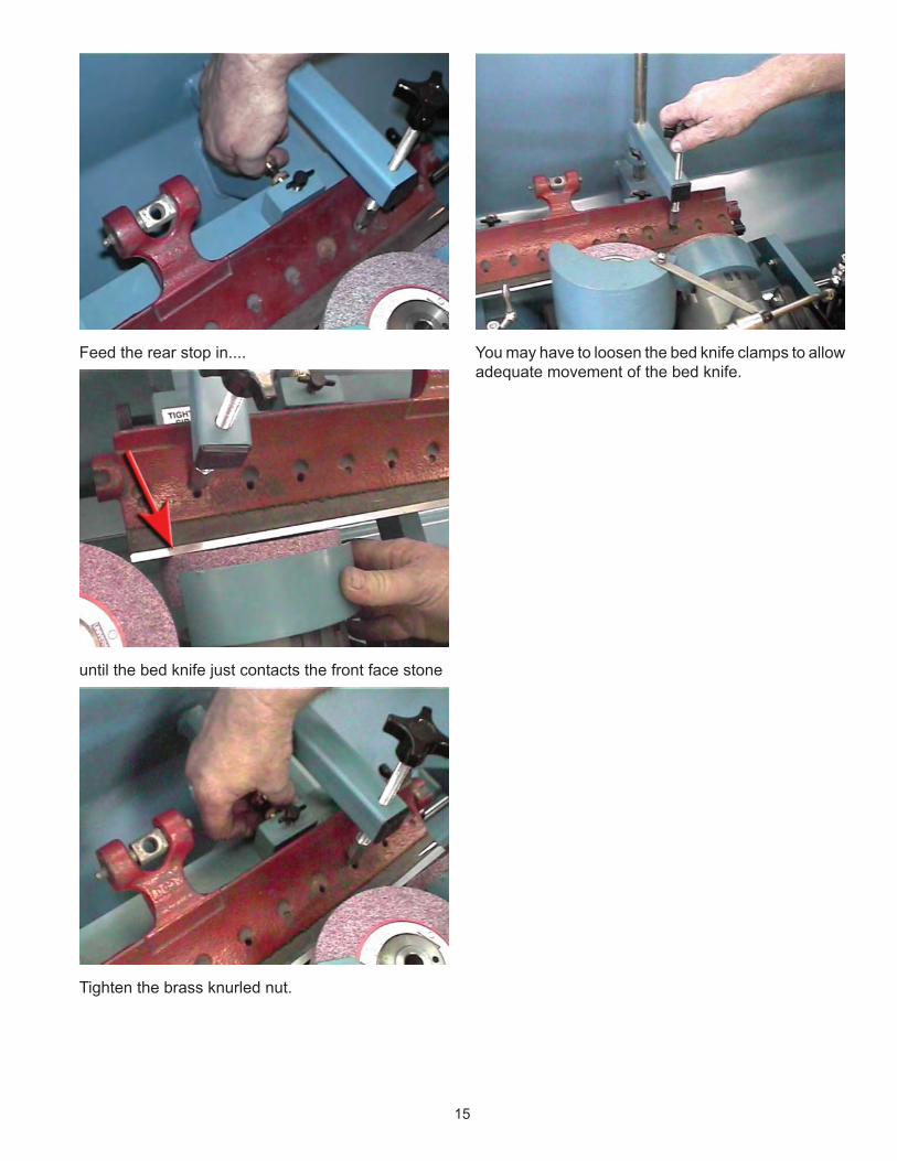
Feedtherearstopin....
untilthebedknifejustcontactsthefrontfacestone
Tightenthebrassknurlednut.
Youmayhavetoloosenthebedknifeclampstoallowadequatemovementofthebedknife.

16
3.8 Checkingcontact
Movethegrindingheadtooneendofthebedknife.
Adjustthetopfacestonedownuntil it justtouchesthebedknife.
Movethegrindingheadacrossthebedknife.Thereshouldbeevencontactallthewayacrossunlessthebedknifeisbadlyworn.Ifthecontactisnoteven,recheckyoursetup.Repeatforthefrontface.
17
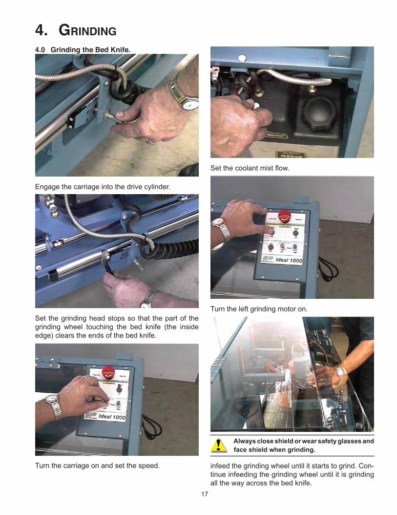
4. grIndIng4.0 GrindingtheBedKnife.
Engagethecarriageintothedrivecylinder.
Set thegrindingheadstopsso that thepartof thegrinding wheel touching the bed knife (the insideedge)clearstheendsofthebedknife.
Turnthecarriageonandsetthespeed.
Set the coolant mist flow.
Turntheleftgrindingmotoron.
Always close shield or wear safety glasses and face shield when grinding.
infeedthegrindingwheeluntilitstartstogrind.Con-tinueinfeedingthegrindingwheeluntilitisgrindingallthewayacrossthebedknife.
18
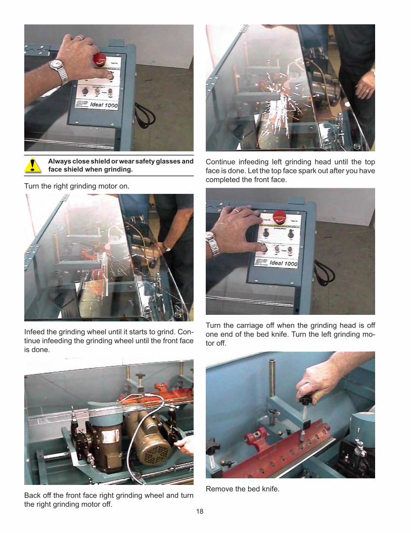
Always close shield or wear safety glasses and face shield when grinding.
Turntherightgrindingmotoron.
Infeedthegrindingwheeluntilitstartstogrind.Con-tinueinfeedingthegrindingwheeluntilthefrontfaceisdone.
Backoffthefrontfacerightgrindingwheelandturntherightgrindingmotoroff.
Continue infeeding left grinding head until the topfaceisdone.Letthetopfacesparkoutafteryouhavecompletedthefrontface.
Turn thecarriageoffwhenthegrindinghead isoffoneendofthebedknife.Turntheleftgrindingmo-toroff.
Removethebedknife.

19
4.1 Dressingthegrindingstone
Unlock the diamond dresser mount. This handleratchetsandmayberepositionedbypullingoutandturning.
Positionthediamonddresseragainstthestoneonitsoutsideoredgethenlockthemount.
Makesurethatyouaredressingontheoutsidehalfofthegrindingwheel,thelefthalfoftheleftstone,
andtherighthalfoftherightstone.
With the grinding head disengaged from the drivecylinder,turnthegrindingmotoronandcarefullymovethegrindingheadbackandforthasyouinfeedthegrindingheaddown.Continueuntilnosparksappear.Turnthegrindingmotoroff.
Stowthediamonddressermount.
20
5. MaIntenance
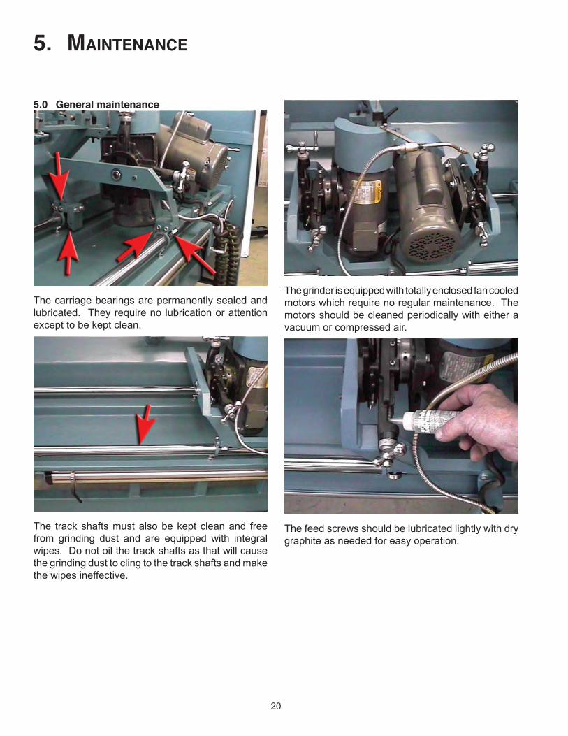
5.0 Generalmaintenance
Thecarriagebearingsarepermanentlysealedandlubricated.Theyrequirenolubricationorattentionexcepttobekeptclean.
The trackshaftsmustalsobekeptcleanand freefrom grinding dust and are equipped with integralwipes.Donotoilthetrackshaftsasthatwillcausethegrindingdusttoclingtothetrackshaftsandmakethewipesineffective.
Thegrinderisequippedwithtotallyenclosedfancooledmotorswhichrequirenoregularmaintenance.Themotorsshouldbecleanedperiodicallywitheitheravacuumorcompressedair.
Thefeedscrewsshouldbelubricatedlightlywithdrygraphiteasneededforeasyoperation.
21
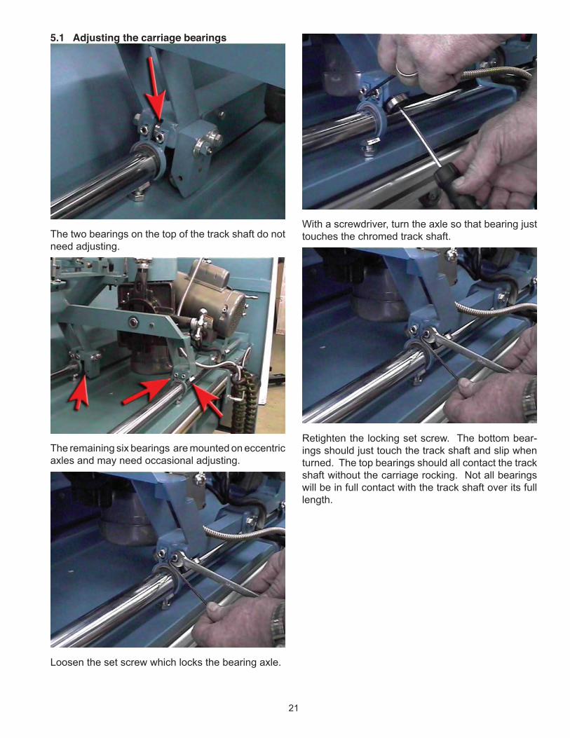
5.1 Adjustingthecarriagebearings
Thetwobearingsonthetopofthetrackshaftdonotneedadjusting.
Theremainingsixbearingsaremountedoneccentricaxlesandmayneedoccasionaladjusting.
Loosenthesetscrewwhichlocksthebearingaxle.
Withascrewdriver,turntheaxlesothatbearingjusttouchesthechromedtrackshaft.
Retightenthelockingsetscrew.Thebottombear-ingsshouldjusttouchthetrackshaftandslipwhenturned.Thetopbearingsshouldallcontactthetrackshaftwithoutthecarriagerocking.Notallbearingswillbeinfullcontactwiththetrackshaftoveritsfulllength.

22
5.2 Mountinggrindingwheels
Do not use damaged grinding wheel as it may come apart and cause damage, serious injury, or loss of life.!
Ringanewgrindingwheeltoensureitisundamaged.Do this by holding it in the arbor hole and gentlytappingitwithawoodenhandleofascrewdriverorsimilartool.Ifthegrindingwheeldoesnotring,donotuseit.
Do not overtighten the nut as it will cause the grinding wheel to explode!
Usingtheu-wrenchprovided,holdthegrindingwheelandunscrewthewheelnut.Theleftgrinderiscoun-terclockwisetoloosen.Therightgrinderisclockwisetoloosen.
Youmayhavetoraisetheleftgrindingheadorlowertherightgrindingheadtobeabletoremovetheleftgrindingwheel.
Placethenewgrindingwheelonthehub.
Replacethewheelnutandtightenwiththeu-wrenchprovided.Donotovertightenasyoumaydamagethegrindingwheel.Useextracautionwhenturningthegrinding motor on and off the first few times after you havemountedthegrindingwheel.Ifthenutisnottightenough,itandthegrindingwheelmaycomeoffwhenyouturnthemotoroff.

23
5.3 Adjustingthegibs
Ifthegrindingheadseemsloose,youmayneedtotighten the gibs by loosening the locking nut andtightening the gib screws. Tighten screws so thatthereisnoplayintheheadbutthefeedscrewworkssmoothly.