ibm system storage ds5100 or ds5300 storage subsystem
TRANSCRIPT

IBM System Storage DS5100 or DS5300 StorageSubsystem
Installation, User’s, and Maintenance Guide
GA32-0955-03
���

IBM System Storage DS5100 or DS5300 StorageSubsystem
Installation, User’s, and Maintenance Guide
GA32-0955-03
���

Note:Before using this information and the product it supports, be sure to read the general information in the “Safety” on page iiiand “Notices” on page 275 sections.
This edition applies to the IBM System Storage DS5100 or DS5300 Storage Subsystem with controller firmwareversion 7.30, and to all subsequent releases and modifications until otherwise indicated in new editions.
This edition replaces GA32-0955-02.
© Copyright IBM Corporation 2008, 2012.US Government Users Restricted Rights – Use, duplication or disclosure restricted by GSA ADP Schedule Contractwith IBM Corp.
Safety
The caution and danger statements that this document contains can be referencedin the multilingual IBM® Safety Information document that is provided with your IBMSystem Storage® DS5100 or DS5300 Storage Subsystem. Each caution and dangerstatement is numbered for easy reference to the corresponding statements in thetranslated document.
v Danger: These statements indicate situations that can be potentially lethal orextremely hazardous to you. A danger statement is placed just before thedescription of a potentially lethal or extremely hazardous procedure, step, orsituation.
v Caution: These statements indicate situations that can be potentially hazardousto you. A caution statement is placed just before the description of a potentiallyhazardous procedure step or situation.
v Attention: These notices indicate possible damage to programs, devices, ordata. An attention notice is placed just before the instruction or situation in whichdamage could occur.
Before installing this product, read the following danger and caution notices.
© Copyright IBM Corp. 2008, 2012 iii
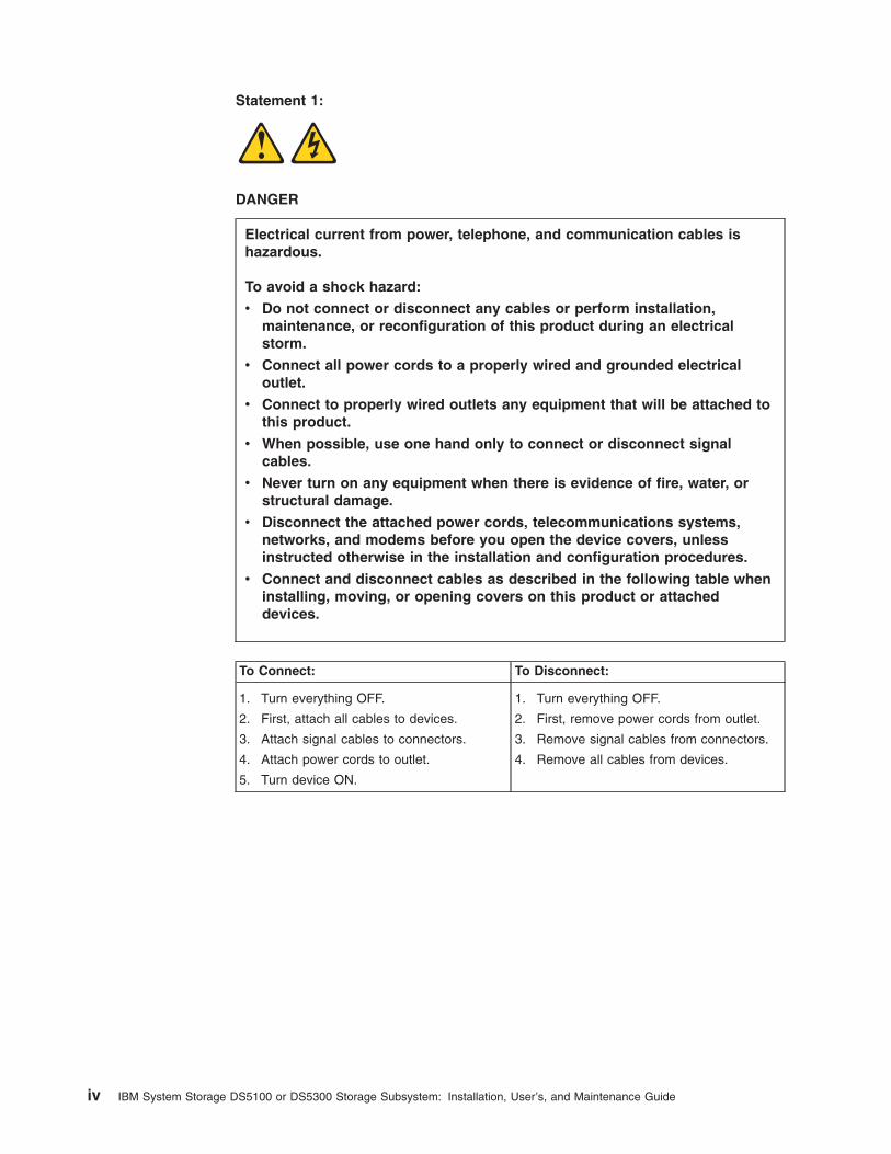
Statement 1:
DANGER
Electrical current from power, telephone, and communication cables ishazardous.
To avoid a shock hazard:
v Do not connect or disconnect any cables or perform installation,maintenance, or reconfiguration of this product during an electricalstorm.
v Connect all power cords to a properly wired and grounded electricaloutlet.
v Connect to properly wired outlets any equipment that will be attached tothis product.
v When possible, use one hand only to connect or disconnect signalcables.
v Never turn on any equipment when there is evidence of fire, water, orstructural damage.
v Disconnect the attached power cords, telecommunications systems,networks, and modems before you open the device covers, unlessinstructed otherwise in the installation and configuration procedures.
v Connect and disconnect cables as described in the following table wheninstalling, moving, or opening covers on this product or attacheddevices.
To Connect: To Disconnect:
1. Turn everything OFF.
2. First, attach all cables to devices.
3. Attach signal cables to connectors.
4. Attach power cords to outlet.
5. Turn device ON.
1. Turn everything OFF.
2. First, remove power cords from outlet.
3. Remove signal cables from connectors.
4. Remove all cables from devices.
iv IBM System Storage DS5100 or DS5300 Storage Subsystem: Installation, User’s, and Maintenance Guide

Statement 2:
CAUTION:When replacing the lithium battery, use only an equivalent type batteryrecommended by the manufacturer. If your system has a module containing alithium battery, replace it only with the same module type made by the samemanufacturer. The battery contains lithium and can explode if not properlyused, handled, or disposed of.
Do not:
v Throw or immerse into water
v Heat to more than 100° C (212° F)
v Repair or disassemble
Dispose of the battery as required by local ordinances or regulations.
Safety v
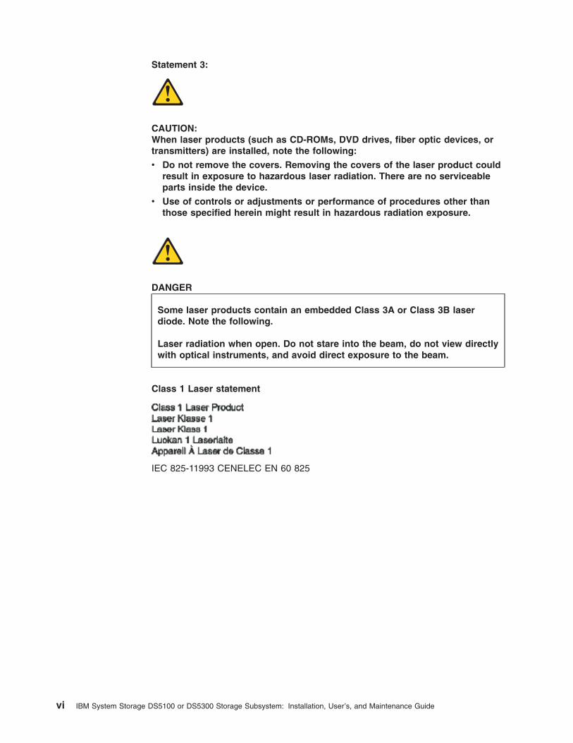
Statement 3:
CAUTION:When laser products (such as CD-ROMs, DVD drives, fiber optic devices, ortransmitters) are installed, note the following:
v Do not remove the covers. Removing the covers of the laser product couldresult in exposure to hazardous laser radiation. There are no serviceableparts inside the device.
v Use of controls or adjustments or performance of procedures other thanthose specified herein might result in hazardous radiation exposure.
DANGER
Some laser products contain an embedded Class 3A or Class 3B laserdiode. Note the following.
Laser radiation when open. Do not stare into the beam, do not view directlywith optical instruments, and avoid direct exposure to the beam.
Class 1 Laser statement
IEC 825-11993 CENELEC EN 60 825
vi IBM System Storage DS5100 or DS5300 Storage Subsystem: Installation, User’s, and Maintenance Guide

Statement 4:
≥ 18 kg (39.7 lb) ≥ 32 kg (70.5 lb) ≥ 55 kg (121.2 lb)
CAUTION:Use safe practices when lifting.
Statement 5:
CAUTION:The power control button on the device and the power switch on the powersupply do not turn off the electrical current supplied to the device. The devicealso might have more than one power cord. To remove all electrical currentfrom the device, ensure that all power cords are disconnected from the powersource.
1
2
Safety vii

Statement 8:
CAUTION:Never remove the cover on a power supply or any part that has the followinglabel attached.
Hazardous voltage, current, and energy levels are present inside anycomponent that has this label attached. There are no serviceable parts insidethese components. If you suspect a problem with one of these parts, contacta service technician.
viii IBM System Storage DS5100 or DS5300 Storage Subsystem: Installation, User’s, and Maintenance Guide
Statement 30:
CAUTION:To reduce the risk of electric shock or energy hazards:
v This equipment must be installed by trained service personnel in arestricted-access location, as defined by the NEC and IEC 60950-1, FirstEdition, The Standard for Safety of Information Technology Equipment.
v Connect the equipment to a reliably grounded safety extra low voltage(SELV) source. An SELV source is a secondary circuit that is designed sothat normal and single fault conditions do not cause the voltages to exceeda safe level (60 V direct current).
v The branch circuit overcurrent protection must be rated 20 A.
v Use 12 American Wire Gauge (AWG) or 2.5 mm2 copper conductor only, notexceeding 4.5 meters in length.
v Incorporate a readily available approved and rated disconnect device in thefield wiring.
CAUTION:This unit has more than one power source. To remove all power from the unit,all dc MAINS must be disconnected.
Cable Warning:
WARNING: Handling the cord on this product or cords associated with accessoriessold with this product, will expose you to lead, a chemical known to the State ofCalifornia to cause cancer, and birth defects or other reproductive harm. Washhands after handling.
Safety ix

x IBM System Storage DS5100 or DS5300 Storage Subsystem: Installation, User’s, and Maintenance Guide

Contents
Safety . . . . . . . . . . . . . . . . . . . . . . . . . . . . iii
Figures . . . . . . . . . . . . . . . . . . . . . . . . . . . xvii
Tables . . . . . . . . . . . . . . . . . . . . . . . . . . . . xxi
About this document . . . . . . . . . . . . . . . . . . . . . xxiiiWho should read this document . . . . . . . . . . . . . . . . . . xxiiiHow this document is organized . . . . . . . . . . . . . . . . . . xxiiiDS4000, DS5100, and DS5300 installation tasks - general overview. . . . . xxivGetting information, help, and service . . . . . . . . . . . . . . . . xxvii
Before you call . . . . . . . . . . . . . . . . . . . . . . . xxviiUsing the documentation . . . . . . . . . . . . . . . . . . . xxviiiFinding Storage Manager software, controller firmware, and README files xxviiiIBM System Storage Productivity Center . . . . . . . . . . . . . xxviiiEssential Web sites for DS4000, DS5100, and DS5300 support information xxixSoftware service and support . . . . . . . . . . . . . . . . . . xxxHardware service and support . . . . . . . . . . . . . . . . . . xxxIBM Taiwan product service . . . . . . . . . . . . . . . . . . . xxxFire suppression systems . . . . . . . . . . . . . . . . . . . xxx
Chapter 1. Introduction . . . . . . . . . . . . . . . . . . . . . . 1Overview . . . . . . . . . . . . . . . . . . . . . . . . . . . 1
Models . . . . . . . . . . . . . . . . . . . . . . . . . . . 1Fibre channel defined . . . . . . . . . . . . . . . . . . . . . . 2SATA defined . . . . . . . . . . . . . . . . . . . . . . . . . 2iSCSI defined . . . . . . . . . . . . . . . . . . . . . . . . . 2Features at a glance . . . . . . . . . . . . . . . . . . . . . . 2Clustering support . . . . . . . . . . . . . . . . . . . . . . . 3
Inventory checklist . . . . . . . . . . . . . . . . . . . . . . . . 4Receiving product updates and support notifications . . . . . . . . . . . 5Best practices guidelines. . . . . . . . . . . . . . . . . . . . . . 6Storage subsystem components . . . . . . . . . . . . . . . . . . . 7
Controllers . . . . . . . . . . . . . . . . . . . . . . . . . 10Controller cable connections . . . . . . . . . . . . . . . . . . 11Setting up IP addresses for DS5100 or DS5300 storage controllers . . . 16Controller memory . . . . . . . . . . . . . . . . . . . . . 19
Power supply and fan units . . . . . . . . . . . . . . . . . . . 21Interconnect-battery unit . . . . . . . . . . . . . . . . . . . . 22SFP modules . . . . . . . . . . . . . . . . . . . . . . . . 24SFP+ modules . . . . . . . . . . . . . . . . . . . . . . . . 25
Software and hardware compatibility and upgrades . . . . . . . . . . . 25Software and firmware support code upgrades . . . . . . . . . . . . 25Determining firmware levels . . . . . . . . . . . . . . . . . . . 26
Specifications . . . . . . . . . . . . . . . . . . . . . . . . . 27Area requirements . . . . . . . . . . . . . . . . . . . . . . 27
Dimensions . . . . . . . . . . . . . . . . . . . . . . . . 27Weight . . . . . . . . . . . . . . . . . . . . . . . . . . 28Shipping dimensions . . . . . . . . . . . . . . . . . . . . . 28
Environmental requirements and specifications . . . . . . . . . . . . 29Temperature and humidity . . . . . . . . . . . . . . . . . . . 29Altitude . . . . . . . . . . . . . . . . . . . . . . . . . . 29Airflow and heat dissipation . . . . . . . . . . . . . . . . . . 30
© Copyright IBM Corp. 2008, 2012 xi

Shock and vibration requirements . . . . . . . . . . . . . . . . 31Acoustic noise . . . . . . . . . . . . . . . . . . . . . . . 31
Electrical requirements . . . . . . . . . . . . . . . . . . . . . 31Site wiring and power . . . . . . . . . . . . . . . . . . . . 32AC power recovery . . . . . . . . . . . . . . . . . . . . . 32Power cords and receptacles. . . . . . . . . . . . . . . . . . 32
Heat output, airflow, and cooling . . . . . . . . . . . . . . . . . 32
Chapter 2. Installing the storage subsystem . . . . . . . . . . . . . 35Installation overview . . . . . . . . . . . . . . . . . . . . . . . 35Handling static-sensitive devices . . . . . . . . . . . . . . . . . . 37Preparing for installation . . . . . . . . . . . . . . . . . . . . . 37
Preparing the site . . . . . . . . . . . . . . . . . . . . . . . 39Preparing the rack cabinet. . . . . . . . . . . . . . . . . . . . 39
Installing the support rails . . . . . . . . . . . . . . . . . . . . . 40Installing the DS5100 or DS5300 . . . . . . . . . . . . . . . . . . 44
Installing the DS5100 or DS5300 on the support rails. . . . . . . . . . 45
Chapter 3. Cabling the storage subsystem. . . . . . . . . . . . . . 49Working with SFPs, SFP+s, and fiber-optic cables . . . . . . . . . . . . 49
Handling fibre-optic cables . . . . . . . . . . . . . . . . . . . 50Installing SFP or SFP+ modules . . . . . . . . . . . . . . . . . 51Removing SFP or SFP+ modules . . . . . . . . . . . . . . . . . 54Installing fiber-optic cables . . . . . . . . . . . . . . . . . . . 55Using LC-LC fibre-channel cables . . . . . . . . . . . . . . . . . 56
Connecting an LC-LC cable to an SFP or SFP+ module. . . . . . . . 58Removing an LC-LC fibre-channel cable . . . . . . . . . . . . . 59
Using LC-SC fibre-channel cable adapters . . . . . . . . . . . . . . 60Connecting an LC-SC cable adapter to a device . . . . . . . . . . 62Removing an LC-LC cable from an LC-SC cable adapter . . . . . . . 63
Connecting storage expansion enclosures to the DS5100 or DS5300 . . . . . 64Redundant drive channel pair . . . . . . . . . . . . . . . . . . 64Non-trunking cabling . . . . . . . . . . . . . . . . . . . . . . 65Drive-side trunking cabling . . . . . . . . . . . . . . . . . . . 73Overview of steps to connect storage expansion enclosure to a storage
subsystem. . . . . . . . . . . . . . . . . . . . . . . . . 76DS5100 or DS5300 drive cabling best practices and rules . . . . . . . . 77
EXP5000 storage expansion enclosure cabling rules . . . . . . . . . 79EXP5060 storage expansion enclosure cabling rules . . . . . . . . . 80
DS5100 or DS5300 drive cabling topologies . . . . . . . . . . . . . 81One DS5100 or DS5300 and one EXP5000 storage expansion enclosure 84One DS5100 or DS5300 and two EXP5000 storage expansion enclosures 85One DS5100 or DS5300 and four EXP5000 storage expansion enclosures 86One DS5100 or DS5300 and eight EXP5000 storage expansion
enclosures. . . . . . . . . . . . . . . . . . . . . . . . 86One DS5100 or DS5300 and sixteen EXP5000 storage expansion
enclosures. . . . . . . . . . . . . . . . . . . . . . . . 88One DS5100 or DS5300 and 28 EXP5000 storage expansion enclosures 90One DS5100 or DS5300 and one EXP5060 storage expansion enclosure 106One DS5100 or DS5300 and two EXP5060 storage expansion enclosures 106One DS5100 or DS5300 and three EXP5060 storage expansion
enclosures . . . . . . . . . . . . . . . . . . . . . . . 107One DS5100 or DS5300 and four EXP5060 storage expansion
enclosures . . . . . . . . . . . . . . . . . . . . . . . 108One DS5100 or DS5300 and eight EXP5060 storage expansion
enclosures . . . . . . . . . . . . . . . . . . . . . . . 110
xii IBM System Storage DS5100 or DS5300 Storage Subsystem: Installation, User’s, and Maintenance Guide
One DS5100 or DS5300 and one EXP5060 intermixed with a maximumof three EXP810/EXP5000 storage expansion enclosures . . . . . . 112
DS5100 or DS5300 storage subsystem and one EXP5060 intermixed witha maximum of seven EXP810/EXP5000 storage expansion enclosures . 116
Drive-side trunking cabling configurations . . . . . . . . . . . . . 117Cabling the storage expansion enclosures to a storage subsystem . . . . 129Storage expansion enclosure settings . . . . . . . . . . . . . . . 130DS5100 or DS5300 storage expansion enclosure ID settings . . . . . . 131Fibre channel loop and ID settings . . . . . . . . . . . . . . . . 132
DS Storage Manager client host port numbering . . . . . . . . . . . . 132Connecting hosts directly to the DS5100 or DS5300 Fibre Channel host ports 132Connecting hosts to the DS5100 or DS5300 iSCSI ports . . . . . . . . . 134Connecting secondary interface cables . . . . . . . . . . . . . . . 135Configuring the storage subsystem . . . . . . . . . . . . . . . . . 136
Storage subsystem management methods . . . . . . . . . . . . . 136Host-agent (in-band) management method . . . . . . . . . . . . 136Direct (out-of-band) management method . . . . . . . . . . . . 137
Fibre channel and iSCSI host connections . . . . . . . . . . . . . 138Fibre channel host loop configurations . . . . . . . . . . . . . . . 139
Redundant host and drive loops . . . . . . . . . . . . . . . . 139iSCSI configurations . . . . . . . . . . . . . . . . . . . . . 143Host iSCSI configurations . . . . . . . . . . . . . . . . . . . 143
Installing the storage subsystem configuration . . . . . . . . . . . . . 147Connecting the power cables . . . . . . . . . . . . . . . . . . . 147
Chapter 4. Operating the storage subsystem . . . . . . . . . . . . 151Performing the DS4000, DS5100, and DS5300 Health Check process . . . . 152
Web pages . . . . . . . . . . . . . . . . . . . . . . . . . 153Hardware responsibilities. . . . . . . . . . . . . . . . . . . . 153
Removing and replacing the front bezel . . . . . . . . . . . . . . . 154Turning the storage subsystem on and off . . . . . . . . . . . . . . 154
Turning on the storage subsystem . . . . . . . . . . . . . . . . 155Turning off the storage subsystem . . . . . . . . . . . . . . . . 157
Restoring power after an unexpected shutdown . . . . . . . . . . . . 160Performing an emergency shutdown . . . . . . . . . . . . . . . 160Restoring power after an emergency shutdown . . . . . . . . . . . 161
Responding to the audible alarm . . . . . . . . . . . . . . . . . . 162Installing the DS Storage Manager client . . . . . . . . . . . . . . . 163Monitoring status through software . . . . . . . . . . . . . . . . . 164
Finding controller, storage expansion enclosure, and drive information 165Firmware updates . . . . . . . . . . . . . . . . . . . . . . 166Troubleshooting the storage subsystem . . . . . . . . . . . . . . 166
Checking the LEDs . . . . . . . . . . . . . . . . . . . . . . . 167Front bezel LEDs . . . . . . . . . . . . . . . . . . . . . . 168RAID controller LEDs . . . . . . . . . . . . . . . . . . . . . 169Seven-segment numeric display LEDs . . . . . . . . . . . . . . . 174Power supply and fan unit LEDs . . . . . . . . . . . . . . . . . 175Interconnect-battery unit LEDs. . . . . . . . . . . . . . . . . . 176
Recovering from an overheated power supply and fan unit . . . . . . . . 179Resetting the controller circuit breakers . . . . . . . . . . . . . . . 181Cache memory and cache battery . . . . . . . . . . . . . . . . . 186
Cache memory . . . . . . . . . . . . . . . . . . . . . . . 186Subsystem cache battery . . . . . . . . . . . . . . . . . . . 187
Chapter 5. Replacing components . . . . . . . . . . . . . . . . 189Handling static-sensitive devices . . . . . . . . . . . . . . . . . . 189
Contents xiii
Service Action Allowed status LED . . . . . . . . . . . . . . . . . 190Single component failures . . . . . . . . . . . . . . . . . . . 190Multiple component failures . . . . . . . . . . . . . . . . . . . 191
Releasing and locking a component lever . . . . . . . . . . . . . . 192Replacing a controller . . . . . . . . . . . . . . . . . . . . . . 193Replacing a DS5100 or DS5300 host interface card . . . . . . . . . . . 199Replacing a power supply and fan unit. . . . . . . . . . . . . . . . 205Replacing the interconnect-battery unit. . . . . . . . . . . . . . . . 209Replacing a backup battery pack . . . . . . . . . . . . . . . . . . 213Replacing a SFP module. . . . . . . . . . . . . . . . . . . . . 217Replacing a SFP+ module . . . . . . . . . . . . . . . . . . . . 219Installing SFPs and fiber-optic cables . . . . . . . . . . . . . . . . 221Removing and disposing of the lithium batteries . . . . . . . . . . . . 221Replacing the cache memory DIMM . . . . . . . . . . . . . . . . 223
Chapter 6. Hardware maintenance . . . . . . . . . . . . . . . . 231General checkout . . . . . . . . . . . . . . . . . . . . . . . 231
Using the diagnostic hardware. . . . . . . . . . . . . . . . . . 231Solving problems . . . . . . . . . . . . . . . . . . . . . . 231
Parts list . . . . . . . . . . . . . . . . . . . . . . . . . . . 238Seven-segment display sequence codes and their causes . . . . . . . . 239Determining basic information of drive FRUs . . . . . . . . . . . . . 243
Appendix A. Additional System Storage DS documentation . . . . . . 245DS Storage Manager Version 10 library . . . . . . . . . . . . . . . 245DS5100 or DS5300 Storage Subsystem library . . . . . . . . . . . . 246DS5020 Storage subsystem library . . . . . . . . . . . . . . . . . 247DS5100 or DS5300 storage subsystem library . . . . . . . . . . . . . 248DS4700 storage subsystem library . . . . . . . . . . . . . . . . . 249DS4500 storage subsystem library . . . . . . . . . . . . . . . . . 250DS4400 storage subsystem library . . . . . . . . . . . . . . . . . 251DS4300 storage subsystem library . . . . . . . . . . . . . . . . . 252DS4200 Express storage subsystem library . . . . . . . . . . . . . . 253DS4100 Storage subsystem library . . . . . . . . . . . . . . . . . 254DS4000 and DS4000 storage expansion enclosure documents. . . . . . . 255Other DS4000 and DS4000-related documents . . . . . . . . . . . . 256
Appendix B. Records . . . . . . . . . . . . . . . . . . . . . 257Identification numbers . . . . . . . . . . . . . . . . . . . . . . 257
Appendix C. Rack mounting templates. . . . . . . . . . . . . . . 259
Appendix D. Specifications for non-IBM rack installation . . . . . . . 263General safety requirements for IBM products installed in a non-IBM rack or
cabinet . . . . . . . . . . . . . . . . . . . . . . . . . . 263Rack specifications . . . . . . . . . . . . . . . . . . . . . . . 265
Appendix E. Power cords . . . . . . . . . . . . . . . . . . . . 271
Appendix F. Accessibility . . . . . . . . . . . . . . . . . . . . 273
Notices . . . . . . . . . . . . . . . . . . . . . . . . . . . 275Trademarks. . . . . . . . . . . . . . . . . . . . . . . . . . 276Important notes . . . . . . . . . . . . . . . . . . . . . . . . 277Particulate contamination. . . . . . . . . . . . . . . . . . . . . 277Documentation format . . . . . . . . . . . . . . . . . . . . . . 278
xiv IBM System Storage DS5100 or DS5300 Storage Subsystem: Installation, User’s, and Maintenance Guide

Electronic emission notices . . . . . . . . . . . . . . . . . . . . 278Federal Communications Commission (FCC) Class A Statement . . . . . 278Industry Canada Class A Emission Compliance Statement . . . . . . . 279Avis de conformité à la réglementation d'Industrie Canada . . . . . . . 279Australia and New Zealand Class A Statement . . . . . . . . . . . . 279European Union EMC Directive Conformance Statement . . . . . . . . 279Germany Electromagnetic Compatibility Directive . . . . . . . . . . . 280Japan Voluntary Control Council for Interference (VCCI) Class A Statement 281Japan Electronics and Information Technology Industries Association (JEITA)
Statement . . . . . . . . . . . . . . . . . . . . . . . . 281Korea Communications Commission (KCC) Class A Statement. . . . . . 281People's Republic of China Class A Electronic Emission Statement . . . . 281Russia Electromagnetic Interference (EMI) Class A Statement . . . . . . 282Taiwan Class A Electronic Emission Statement. . . . . . . . . . . . 282
Glossary . . . . . . . . . . . . . . . . . . . . . . . . . . 283
Index . . . . . . . . . . . . . . . . . . . . . . . . . . . . 293
Contents xv

xvi IBM System Storage DS5100 or DS5300 Storage Subsystem: Installation, User’s, and Maintenance Guide
Figures
1. DS5100 or DS5300 Storage Subsystem. . . . . . . . . . . . . . . . . . . . . . . 72. Location of components in the storage subsystem . . . . . . . . . . . . . . . . . . . 83. Controllers in the storage subsystem . . . . . . . . . . . . . . . . . . . . . . . 114. Fibre Channel Controller connections . . . . . . . . . . . . . . . . . . . . . . . 125. 1 Gbps iSCSI Controller connections . . . . . . . . . . . . . . . . . . . . . . . 126. 10 Gbps iSCSI Controller connections . . . . . . . . . . . . . . . . . . . . . . . 137. Host interface card slots on controllers A and B . . . . . . . . . . . . . . . . . . . 148. Power supply and fan unit . . . . . . . . . . . . . . . . . . . . . . . . . . . 229. Interconnect-battery unit . . . . . . . . . . . . . . . . . . . . . . . . . . . . 23
10. SFP module with fiber-optic cable . . . . . . . . . . . . . . . . . . . . . . . . 2511. DS5100 or DS5300 Storage Subsystem dimensions . . . . . . . . . . . . . . . . . . 2812. DS5100 or DS5300 airflow . . . . . . . . . . . . . . . . . . . . . . . . . . . 3013. Example of cold aisle/hot aisle rack cabinet configuration . . . . . . . . . . . . . . . . 3314. DS5100 or DS5300 front rack mounting template . . . . . . . . . . . . . . . . . . . 4115. DS5100 or DS5300 rear rack mounting template . . . . . . . . . . . . . . . . . . . 4216. DS5100 or DS5300 support rail assembly . . . . . . . . . . . . . . . . . . . . . 4317. DS5100 or DS5300 front views and back view . . . . . . . . . . . . . . . . . . . . 4518. Securing the DS5100 or DS5300 to the rack cabinet. . . . . . . . . . . . . . . . . . 4719. Best practice bending and looping specifications for fibre-optic cables . . . . . . . . . . . 5120. Small Form-Factor Pluggable (SFP or SFP+) module . . . . . . . . . . . . . . . . . 5321. Replacing an SFP or SFP+ module . . . . . . . . . . . . . . . . . . . . . . . . 5422. Unlocking the SFP module latch - plastic variety . . . . . . . . . . . . . . . . . . . 5523. Unlocking the SFP or SFP+ module latch - wire variety. . . . . . . . . . . . . . . . . 5524. Removing caps from fiber-optic cables . . . . . . . . . . . . . . . . . . . . . . . 5625. Connecting fiber-optic cable to SFP or SFP+ . . . . . . . . . . . . . . . . . . . . 5626. LC-LC fibre-channel cable . . . . . . . . . . . . . . . . . . . . . . . . . . . 5727. Removing fiber-optic cable protective caps . . . . . . . . . . . . . . . . . . . . . 5828. Inserting an LC-LC fibre-channel cable into an SFP or SFP+ module . . . . . . . . . . . 5929. LC-LC fibre-channel cable lever and latches . . . . . . . . . . . . . . . . . . . . . 5930. Removing the LC-LC fibre-channel cable . . . . . . . . . . . . . . . . . . . . . . 6031. LC-SC fibre-channel cable adapter . . . . . . . . . . . . . . . . . . . . . . . . 6032. Removing the LC-SC cable adapter protective caps . . . . . . . . . . . . . . . . . . 6233. Connecting an LC-LC cable into the LC-SC cable adapter . . . . . . . . . . . . . . . 6334. LC-LC fibre-channel cable lever and latches . . . . . . . . . . . . . . . . . . . . . 6335. Removing the LC-LC fibre-channel cable from an LC-SC fibre-channel cable adapter . . . . . 6436. Example of redundant drive channel pairs . . . . . . . . . . . . . . . . . . . . . 6537. One DS5100 or DS5300 and two EXP5000 storage expansion enclosures using a non-trunking
cabling scheme . . . . . . . . . . . . . . . . . . . . . . . . . . . . . . . 6638. Example of EXP5060 storage expansion enclosure with non-trunking cabling . . . . . . . . 6639. One DS5100 or DS5300 cabled to two EXP5000s behind the same DS5100/DS5300 drive
channel port using a non-trunking cabling scheme . . . . . . . . . . . . . . . . . . 6740. Example of cascading EXP5060s in non-trunking cabling scheme . . . . . . . . . . . . . 6841. Preferred EXP5060 and EXP5000 intermixing behind the same controller drive channel port 6942. EXP5060 and EXP5000 intermixing behind the same controller drive channel port. . . . . . . 7043. EXP5060 and EXP5000 intermixing behind different controller drive channel ports that are
connected in the same controller drive channel. . . . . . . . . . . . . . . . . . . . 7144. EXP5060 and EXP5000 in different controller drive channels . . . . . . . . . . . . . . 7245. EXP5060 in trunking cabling scheme . . . . . . . . . . . . . . . . . . . . . . . 7546. An example of trunking cabling that is improperly wired . . . . . . . . . . . . . . . . 7547. Cascading EXP5060s in trunking cabling scheme . . . . . . . . . . . . . . . . . . . 7648. EXP5000 port labels . . . . . . . . . . . . . . . . . . . . . . . . . . . . . 8049. EXP5060 port labels . . . . . . . . . . . . . . . . . . . . . . . . . . . . . 8050. DS5100 or DS5300 ports and controllers with Fibre Channel host connections . . . . . . . . 82
© Copyright IBM Corp. 2008, 2012 xvii

51. DS5100 or DS5300 ports and controllers with iSCSI host connections . . . . . . . . . . . 8352. One DS5100 or DS5300 and one EXP5000 storage expansion enclosure . . . . . . . . . . 8553. One DS5100 or DS5300 and two EXP5000 storage expansion enclosures . . . . . . . . . 8554. One DS5100 or DS5300 and four EXP5000 storage expansion enclosures . . . . . . . . . 8655. One DS5100 or DS5300 and eight EXP5000 storage expansion enclosures . . . . . . . . . 8756. One DS5100 or DS5300 and sixteen EXP5000 storage expansion enclosures . . . . . . . . 8857. One DS5100 or DS5300 and 28 EXP5000 storage expansion enclosures - Enclosures 1 to 4 9058. One DS5100 or DS5300 and 28 EXP5000 storage expansion enclosures - Enclosures 5 to 7 9259. One DS5100 or DS5300 and 28 EXP5000 storage expansion enclosures - Enclosures 8 to 11 9460. One DS5100 or DS5300 and 28 EXP5000 storage expansion enclosures - Enclosures 12 to 14 9661. One DS5100 or DS5300 and 28 EXP5000 storage expansion enclosures - Enclosures 15 to 18 9862. One DS5100 or DS5300 and 28 EXP5000 storage expansion enclosures - Enclosures 19 to 21 10063. One DS5100 or DS5300 and 28 EXP5000 storage expansion enclosures - Enclosures 22 to 25 10264. One DS5100 or DS5300 and 28 EXP5000 storage expansion enclosures - Enclosures 26 to 28 10465. Cabling for DS5100 or DS5300 storage subsystem with one EXP5060 storage expansion
enclosure without trunking . . . . . . . . . . . . . . . . . . . . . . . . . . . 10666. Cabling for DS5100 or DS5300 storage subsystem with two EXP5060 storage expansion
enclosures without trunking . . . . . . . . . . . . . . . . . . . . . . . . . . 10767. Cabling for DS5100 or DS5300 storage subsystem with three EXP5060 storage expansion
enclosures without trunking . . . . . . . . . . . . . . . . . . . . . . . . . . 10868. Cabling for DS5100 or DS5300 storage subsystem with four EXP5060 storage expansion
enclosures without trunking . . . . . . . . . . . . . . . . . . . . . . . . . . 10969. Cabling for DS5100 or DS5300 storage subsystem with eight EXP5060 storage expansion
enclosures without trunking. . . . . . . . . . . . . . . . . . . . . . . . . . . 11170. Cabling for DS5100 or DS5300 storage subsystem and one EXP5060 intermixed with a
maximum of three EXP810/EXP5000 storage expansion enclosures without trunking (example 1) 11371. Cabling for DS5100 or DS5300 storage subsystem and one EXP5060 intermixed with a
maximum of three EXP810/EXP5000 storage expansion enclosures without trunking (example 2) 11472. Cabling for DS5100 or DS5300 storage subsystem and one EXP5060 intermixed with a
maximum of three EXP810/EXP5000 storage expansion enclosures without trunking (example 3) 11573. Cabling for DS5100 or DS5300 storage subsystem and one EXP5060 intermixed with a
maximum of seven EXP810/EXP5000 storage expansion enclosures and drive-side trunking . . 11674. Cabling for DS5100 or DS5300 storage subsystem with one EXP5060 storage expansion
enclosure with drive-side trunking . . . . . . . . . . . . . . . . . . . . . . . . 11775. Cabling for DS5100 or DS5300 storage subsystem with two EXP5060 storage expansion
enclosures and drive-side trunking . . . . . . . . . . . . . . . . . . . . . . . . 11876. Cabling for DS5100 or DS5300 storage subsystem with four EXP5060 storage expansion
enclosures and drive-side trunking . . . . . . . . . . . . . . . . . . . . . . . . 11977. Cabling for eight EXP5060s, storage expansion enclosures 1 and 2 with drive-side trunking 12278. Cabling for eight EXP5060s, storage expansion enclosures 3 and 4 with drive-side trunking 12479. Cabling for eight EXP5060s, storage expansion enclosures 5 and 6 with drive-side trunking 12680. Cabling for eight EXP5060s, storage expansion enclosures 7 and 8 with drive-side trunking 12881. Installing an SFP module and LC-LC cable in a DS5100 or DS5300 . . . . . . . . . . . 13082. Installing an SFP module and connecting an LC-LC cable to the storage expansion enclosures 13083. Location of host cables on RAID controllers . . . . . . . . . . . . . . . . . . . . 13384. Cabling diagram for eight redundant host connections. . . . . . . . . . . . . . . . . 13485. Cabling diagram for redundant iSCSI host connections . . . . . . . . . . . . . . . . 13586. Ethernet and serial port locations . . . . . . . . . . . . . . . . . . . . . . . . 13687. Host-agent (in-band) managed storage subsystems . . . . . . . . . . . . . . . . . 13788. Direct (out-of-band) managed storage subsystems . . . . . . . . . . . . . . . . . . 13889. Examples of redundant host direct attached fibre channel configurations . . . . . . . . . . 14090. Example of redundant SAN fabric fibre channel configuration . . . . . . . . . . . . . . 14091. Example of a single SAN fabric configuration . . . . . . . . . . . . . . . . . . . . 14192. Example of two storage subsystems in a single SAN fabric environment . . . . . . . . . . 14193. Example of a two-cluster configuration . . . . . . . . . . . . . . . . . . . . . . 14294. Example of a single SAN fabric configuration with one FC switch . . . . . . . . . . . . 142
xviii IBM System Storage DS5100 or DS5300 Storage Subsystem: Installation, User’s, and Maintenance Guide
95. Example of a dual SAN fabric configuration with two FC switches . . . . . . . . . . . . 14396. Example of a single-host, multiple-port configuration . . . . . . . . . . . . . . . . . 14497. Example of a multiple-host, multiple-port configuration . . . . . . . . . . . . . . . . 14598. Example of iSCSI and Fibre Channel hosts, multiple-port configuration . . . . . . . . . . 14599. Example of an incorrect configuration: Single-host, iSCSI and Fibre Channel . . . . . . . . 146
100. Example of a multiple-host, multiple-port, multiple-switch configuration. . . . . . . . . . . 147101. AC power switch and ac power connector . . . . . . . . . . . . . . . . . . . . . 148102. Redundant ac power connections to controllers and storage expansion enclosures . . . . . . 150103. Installing the front bezel . . . . . . . . . . . . . . . . . . . . . . . . . . . . 154104. AC power switches on the controllers . . . . . . . . . . . . . . . . . . . . . . . 156105. Front bezel LEDs . . . . . . . . . . . . . . . . . . . . . . . . . . . . . . 168106. Fibre Channel RAID controller LEDs . . . . . . . . . . . . . . . . . . . . . . . 169107. 1 Gbps iSCSI RAID controller LEDs . . . . . . . . . . . . . . . . . . . . . . . 170108. Numeric display LEDs . . . . . . . . . . . . . . . . . . . . . . . . . . . . 174109. Power supply and fan unit LEDs. . . . . . . . . . . . . . . . . . . . . . . . . 175110. Interconnect-battery unit LEDs . . . . . . . . . . . . . . . . . . . . . . . . . 177111. Power supply and fan unit Needs Attention LEDs . . . . . . . . . . . . . . . . . . 182112. RAID controller connections with Fibre Channel host connections . . . . . . . . . . . . 183113. RAID controller connections with iSCSI host connections . . . . . . . . . . . . . . . 183114. Removing the controller from the storage subsystem . . . . . . . . . . . . . . . . . 184115. Circuit breaker access hole . . . . . . . . . . . . . . . . . . . . . . . . . . 184116. Cache Active LEDs . . . . . . . . . . . . . . . . . . . . . . . . . . . . . 187117. Battery LEDs . . . . . . . . . . . . . . . . . . . . . . . . . . . . . . . . 188118. Component lever and latch . . . . . . . . . . . . . . . . . . . . . . . . . . 192119. RAID controller Needs Attention and Service Action Allowed LEDs . . . . . . . . . . . . 194120. Connectors on the back of each controller. Each host channel is different, dependent on the host
interface card. . . . . . . . . . . . . . . . . . . . . . . . . . . . . . . . 195121. Unlocking the SFP module latch - plastic variety . . . . . . . . . . . . . . . . . . . 196122. Unlocking the SFP module latch - wire variety . . . . . . . . . . . . . . . . . . . 196123. Removing a controller from the DS5100 or DS5300 . . . . . . . . . . . . . . . . . 197124. Removing and reinstalling a controller . . . . . . . . . . . . . . . . . . . . . . 201125. Removing controller cover and replacing host interface card . . . . . . . . . . . . . . 202126. Host interface card slots on controllers A and B . . . . . . . . . . . . . . . . . . . 203127. Controller Service Action LEDs . . . . . . . . . . . . . . . . . . . . . . . . . 204128. Overall Configuration Needs Attention LED on the DS5100 or DS5300 front bezel . . . . . . 207129. Power supply and fan unit LEDs. . . . . . . . . . . . . . . . . . . . . . . . . 207130. Removing a power supply and fan unit from the DS5100 or DS5300 . . . . . . . . . . . 208131. Overall Configuration Needs Attention LED on the DS5100 or DS5300 front bezel . . . . . . 210132. Interconnect-battery unit Needs Attention and Service Action Allowed LEDs . . . . . . . . . 211133. Removing an interconnect-battery unit from the DS5100 or DS5300 . . . . . . . . . . . 212134. Overall Configuration Needs Attention LED on the DS5100 or DS5300 front bezel . . . . . . 214135. Battery access cover on the interconnect-battery unit . . . . . . . . . . . . . . . . . 215136. Overall Configuration Needs Attention LED on the DS5100 or DS5300 front bezel . . . . . . 217137. Needs Attention and SFP Model Bypass LEDs . . . . . . . . . . . . . . . . . . . 218138. Replacing a SFP or SFP+ module . . . . . . . . . . . . . . . . . . . . . . . . 218139. Removing a controller . . . . . . . . . . . . . . . . . . . . . . . . . . . . 225140. Controller top cover, internal parts, and faceplate . . . . . . . . . . . . . . . . . . 226141. Numbers indicate cache memory DIMM locations . . . . . . . . . . . . . . . . . . 227142. Removing a cache memory DIMM . . . . . . . . . . . . . . . . . . . . . . . . 227143. Numbers indicate cache backup memory device Locations . . . . . . . . . . . . . . . 228144. Controller Service Action LEDs . . . . . . . . . . . . . . . . . . . . . . . . . 229145. DS5100 or DS5300 parts list . . . . . . . . . . . . . . . . . . . . . . . . . . 238146. Seven-segment alphanumeric characters . . . . . . . . . . . . . . . . . . . . . 240147. An IBM hologram label example. . . . . . . . . . . . . . . . . . . . . . . . . 244148. Location of MAC address labels . . . . . . . . . . . . . . . . . . . . . . . . . 258149. DS5100 or DS5300 front rack mounting template . . . . . . . . . . . . . . . . . . 260
Figures xix

150. DS5100 or DS5300 rear rack mounting template . . . . . . . . . . . . . . . . . . 261151. Top View of non-IBM Rack Specifications Dimensions. . . . . . . . . . . . . . . . . 266152. Rack specifications dimensions, top front view . . . . . . . . . . . . . . . . . . . 267153. Rack specifications dimensions, bottom front view . . . . . . . . . . . . . . . . . . 267
xx IBM System Storage DS5100 or DS5300 Storage Subsystem: Installation, User’s, and Maintenance Guide

Tables
1. Where to find DS4000, DS5100, and DS5300 installation and configuration procedures . . . . xxiv2. Features at a glance . . . . . . . . . . . . . . . . . . . . . . . . . . . . . . 33. Maximum number of storage expansion enclosures . . . . . . . . . . . . . . . . . . 94. Description of numbered locations in the figure that shows host interface card slots on controllers
A and B . . . . . . . . . . . . . . . . . . . . . . . . . . . . . . . . . . 145. Default IP addresses and subnet masks . . . . . . . . . . . . . . . . . . . . . . 156. RAID controller specifications . . . . . . . . . . . . . . . . . . . . . . . . . . 197. Minimum controller firmware level required by some options . . . . . . . . . . . . . . . 258. DS5100 or DS5300 Storage Subsystem weights . . . . . . . . . . . . . . . . . . . 289. DS5100 or DS5300 component weights . . . . . . . . . . . . . . . . . . . . . . 28
10. DS5100 or DS5300 shipping carton dimensions . . . . . . . . . . . . . . . . . . . 2911. Temperature and humidity requirements . . . . . . . . . . . . . . . . . . . . . . 2912. DS5100 or DS5300 altitude ranges . . . . . . . . . . . . . . . . . . . . . . . . 2913. DS5100 or DS5300 power and heat dissipation . . . . . . . . . . . . . . . . . . . 3014. DS5100 or DS5300 operational vibration specifications . . . . . . . . . . . . . . . . . 3115. DS5100 or DS5300 sound levels . . . . . . . . . . . . . . . . . . . . . . . . . 3116. IBM System Storage DS5100 or DS5300 ac power requirements . . . . . . . . . . . . . 3217. Maximum number of drives per drive channel by enclosure type . . . . . . . . . . . . . 6518. Number of EXP5060 storage expansion enclosures per port and drive channel (non trunking
cabling) . . . . . . . . . . . . . . . . . . . . . . . . . . . . . . . . . . 7819. Number of EXP5060 storage expansion enclosures per port and drive channel (trunking cabling) 7820. Number of storage expansion enclosures per port and drive channel. . . . . . . . . . . . 7821. DS5100 or DS5300 drive ports and drive channels . . . . . . . . . . . . . . . . . . 8322. Description of the figure that shows the DS5100 or DS5300 and one EXP5000 storage expansion
enclosure . . . . . . . . . . . . . . . . . . . . . . . . . . . . . . . . . 8523. One DS5100 or DS5300 and 28 EXP5000 storage expansion enclosures - Enclosures 1 to 4 9124. One DS5100 or DS5300 and 28 EXP5000 storage expansion enclosures - Enclosures 5 to 7 9325. One DS5100 or DS5300 and 28 EXP5000 storage expansion enclosures - Enclosures 8 to 11 9526. One DS5100 or DS5300 and 28 EXP5000 storage expansion enclosures - Enclosures 12 to 14 9727. One DS5100 or DS5300 and 28 EXP5000 storage expansion enclosures - Enclosures 15 to 18 9928. One DS5100 or DS5300 and 28 EXP5000 storage expansion enclosures - Enclosures 19 to 21 10129. One DS5100 or DS5300 and 28 EXP5000 storage expansion enclosures - Enclosures 22 to 25 10330. One DS5100 or DS5300 and 28 EXP5000 storage expansion enclosures - Enclosures 26 to 28 10531. Cabling for DS5100 or DS5300 storage subsystem with one EXP5060 storage expansion
enclosure without trunking . . . . . . . . . . . . . . . . . . . . . . . . . . . 10632. Cabling for DS5100 or DS5300 storage subsystem with two EXP5060 storage expansion
enclosures without trunking . . . . . . . . . . . . . . . . . . . . . . . . . . 10733. Cabling for DS5100 or DS5300 storage subsystem with three EXP5060 storage expansion
enclosures without trunking . . . . . . . . . . . . . . . . . . . . . . . . . . 10834. Cabling for DS5100 or DS5300 storage subsystem with four EXP5060 storage expansion
enclosures without trunking . . . . . . . . . . . . . . . . . . . . . . . . . . 10935. Cabling for DS5100 or DS5300 storage subsystem with eight EXP5060 storage expansion
enclosures without trunking . . . . . . . . . . . . . . . . . . . . . . . . . . 11236. Cabling for the first EXP5060 storage expansion enclosure with drive-side trunking . . . . . . 11737. Cabling for the first EXP5060 storage expansion enclosure with drive-side trunking . . . . . . 11838. Cabling for the second EXP5060 storage expansion enclosure with drive-side trunking . . . . 11839. Cabling for the first EXP5060 storage expansion enclosure with drive-side trunking . . . . . . 12040. Cabling for the second EXP5060 storage expansion enclosure with drive-side trunking . . . . 12041. Cabling for the third EXP5060 storage expansion enclosure with drive-side trunking . . . . . 12042. Cabling for the fourth EXP5060 storage expansion enclosure with drive-side trunking . . . . . 12043. Cabling for eight EXP5060s, storage expansion enclosures 1 and 2 with drive-side trunking 12344. Cabling for eight EXP5060s, storage expansion enclosures 3 and 4 with drive-side trunking 12545. Cabling for eight EXP5060s, storage expansion enclosures 5 and 6 with drive-side trunking 127
© Copyright IBM Corp. 2008, 2012 xxi

46. Cabling for eight EXP5060s, storage expansion enclosures 7 and 8 with drive-side trunking 12947. Best practice enclosure ID settings scheme . . . . . . . . . . . . . . . . . . . . 13148. Description of numbered locations in the figure that shows host-agent (in-band) managed
storage subsystems . . . . . . . . . . . . . . . . . . . . . . . . . . . . . 13749. Description of numbered locations in the figure that shows direct (out-of-band) managed storage
subsystems . . . . . . . . . . . . . . . . . . . . . . . . . . . . . . . . 13850. Description of the figure that shows locations of the front bezel LEDs . . . . . . . . . . . 16851. RAID controller LEDs. . . . . . . . . . . . . . . . . . . . . . . . . . . . . 17052. Host and drive channel LED definitions . . . . . . . . . . . . . . . . . . . . . . 17353. Power supply and fan unit LEDs. . . . . . . . . . . . . . . . . . . . . . . . . 17654. Interconnect-battery unit LEDs . . . . . . . . . . . . . . . . . . . . . . . . . 17755. Description of numbered locations in the figure that shows removing and reinstalling a controller 20156. Description of numbered locations in the figure that shows removing a controller cover and
replacing a host interface card . . . . . . . . . . . . . . . . . . . . . . . . . 20257. Description of numbered locations in the figure that shows host interface card slots on controllers
A and B. . . . . . . . . . . . . . . . . . . . . . . . . . . . . . . . . . 20358. Description of numbered locations in the figure that shows the controller Service Action LEDs 20459. cache memory DIMM configurations . . . . . . . . . . . . . . . . . . . . . . . 22660. cache backup memory device configurations . . . . . . . . . . . . . . . . . . . . 22861. Symptom-to-FRU index . . . . . . . . . . . . . . . . . . . . . . . . . . . . 23262. Parts list (System Storage DS5100 or DS5300 Storage Subsystem) . . . . . . . . . . . 23863. Seven-segment display sequence code definitions . . . . . . . . . . . . . . . . . . 24064. Repeating sequences on the seven-segment display and corresponding errors . . . . . . . 24165. Controller numeric display diagnostic codes . . . . . . . . . . . . . . . . . . . . 24366. DS Storage Manager Version 10 titles by user tasks . . . . . . . . . . . . . . . . . 24567. DS5100 or DS5300 Storage Subsystem document titles by user tasks . . . . . . . . . . 24668. DS5020 Storage subsystem document titles by user tasks . . . . . . . . . . . . . . . 24769. DS5100 or DS5300 storage subsystem document titles by user tasks . . . . . . . . . . . 24870. DS4700 storage subsystem document titles by user tasks . . . . . . . . . . . . . . . 24971. DS4500 storage subsystem document titles by user tasks . . . . . . . . . . . . . . . 25072. DS4400 storage subsystem document titles by user tasks . . . . . . . . . . . . . . . 25173. DS4300 storage subsystem document titles by user tasks . . . . . . . . . . . . . . . 25274. DS4200 Express storage subsystem document titles by user tasks . . . . . . . . . . . . 25375. DS4100 storage subsystem document titles by user tasks . . . . . . . . . . . . . . . 25476. DS4000 and DS4000 storage expansion enclosure document titles by user tasks . . . . . . 25577. DS4000 and DS4000-related document titles by user tasks. . . . . . . . . . . . . . . 25678. DS4000 Storage Manager alternate keyboard operations . . . . . . . . . . . . . . . 27379. Limits for particulates and gases . . . . . . . . . . . . . . . . . . . . . . . . 278
xxii IBM System Storage DS5100 or DS5300 Storage Subsystem: Installation, User’s, and Maintenance Guide

About this document
This document provides instructions for installing and customizing the configurationof your IBM System Storage DS5100 or DS5300 Storage Subsystem. It alsoprovides hardware maintenance procedures and troubleshooting information.
Who should read this documentThis document is intended for system operators and service technicians who haveextensive knowledge of fibre channel and network technology.
How this document is organizedChapter 1, “Introduction,” on page 1 describes the IBM System Storage DS5100 orDS5300. This chapter includes an inventory checklist and an overview of thestorage subsystem features, operating specifications, and components.
Chapter 2, “Installing the storage subsystem,” on page 35 contains instructions forinstalling the DS5100 or DS5300 in a standard rack cabinet and setting theinterface options.
Chapter 3, “Cabling the storage subsystem,” on page 49 contains fibre channel andpower cabling information for the DS5100 or DS5300.
Chapter 4, “Operating the storage subsystem,” on page 151 contains instructions forpowering the DS5100 or DS5300 on or off during either normal or emergencysituations. It also contains information on how to check the LEDs on the front andback of the storage subsystem.
Chapter 5, “Replacing components,” on page 189 contains step-by-step instructionsfor how to install or remove field replaceable units (FRUs), such as power supplyand fan units, RAID controllers, host interface cards, and interconnect-battery units.
Chapter 6, “Hardware maintenance,” on page 231 contains problems, symptoms,and error messages that are specific to the DS5100 or DS5300. It also contains theparts listing for the DS5100 or DS5300.
Appendix A, “Additional System Storage DS documentation,” on page 245 providesreferences to other DS5100 or DS5300 publications.
Appendix B, “Records,” on page 257 provides a table that you can use to recordand update important information about your DS5100 or DS5300, including serialnumber, model and machine type, and MAC addresses.
Appendix C, “Rack mounting templates,” on page 259 provides the rack mountingtemplates for installation of the DS5100 or DS5300. If you want to tear out thetemplates from the document for use during installation, use these copies of thetemplates.
Appendix E, “Power cords,” on page 271 lists power cord information for theDS5100 or DS5300.
Appendix F, “Accessibility,” on page 273 provides information about System StorageDS® Storage Manager accessibility features.
© Copyright IBM Corp. 2008, 2012 xxiii

DS4000, DS5100, and DS5300 installation tasks - general overviewTable 1 provides a sequential list of many installation and configuration tasks thatare common to most DS4000, DS5100, and DS5300 configurations. When youinstall and configure your DS4000, DS5100, and DS5300, refer to this table to findthe documentation that explains how to complete each task.
See also: The DS4000, DS5100, and DS5300 Quick Start Guides for your storagesubsystem configuration provides an excellent overview of theinstallation process.
Table 1. Where to find DS4000, DS5100, and DS5300 installation and configurationprocedures
Installation task Where to find information or procedures
1 Plan the installation v IBM System Storage DS Storage Manager Version 10Installation and Host Support Guide
v IBM System Storage DS3000, DS4000, and DS5000Command Line Interface and Script Commands ProgrammingGuide
v IBM System Storage Quick Start Guide for the followingstorage subsystems:
– DS5100 or DS5300
– DS4800
– DS4200 and DS4700
v IBM System Storage DSxxxx Installation, User’s, andMaintenance Guide for the following storage subsystems:
– DS5100 or DS5300
– DS4800
– DS4700
– DS4500
– DS4400
– DS4300
– DS4200
– DS4100
2 Mount the DS4000,DS5100, andDS5300 storagesubsystem in therack
v IBM System Storage Quick Start Guide for the followingstorage subsystems:
– DS5100 or DS5300
– DS4800
– DS4200 and DS4700
v IBM System Storage DSxxxx Installation, User’s, andMaintenance Guide for the following storage subsystems:
– DS5100 or DS5300
– DS4800
– DS4700
– DS4200
– DS4100
v DS4400 and DS4500 Rack Mounting Instructions
v DS4300 Rack Mounting Instructions
xxiv IBM System Storage DS5100 or DS5300 Storage Subsystem: Installation, User’s, and Maintenance Guide

Table 1. Where to find DS4000, DS5100, and DS5300 installation and configurationprocedures (continued)
Installation task Where to find information or procedures
3 Mount the DS4000,DS5100, andDS5300 EXP storageexpansion unit in therack
v IBM System Storage Quick Start Guide for the followingstorage subsystems:
– DS5100 or DS5300
– DS4800
– DS4200 and DS4700
v IBM System Storage EXPxxx Installation, User’s, andMaintenance Guide for the following storage expansionenclosures:
– EXP5060
– EXP5000
– EXP810
– EXP700 and EXP710
– EXP500
– EXP420
– EXP100
4 Route the storageexpansion enclosureFibre Channel cables
v IBM System Storage Quick Start Guide for the followingstorage subsystems:
– DS5100 or DS5300
– DS4800
– DS4200 and DS4700
v IBM System Storage EXPxxx Installation, User’s, andMaintenance Guide for the following storage expansionenclosures:
– EXP5060
– EXP5000
– EXP810
– EXP700 and EXP710
– EXP500
– EXP420
– EXP100
5 Route the hostserver Fibre Channelcables
v IBM System Storage Quick Start Guide for the followingstorage subsystems:
– DS5100 or DS5300
– DS4800
– DS4200 and DS4700
v IBM System Storage DSxxxx Installation, User’s, andMaintenance Guide for the following storage subsystems:
– DS5100 or DS5300
– DS4800
– DS4700
– DS4500
– DS4300
– DS4200
– DS4100
v IBM TotalStorage DS4400 Fibre Channel Cabling Instructions
About this document xxv

Table 1. Where to find DS4000, DS5100, and DS5300 installation and configurationprocedures (continued)
Installation task Where to find information or procedures
6 Power on thesubsystem
v IBM System Storage Quick Start Guide for the followingstorage subsystems:
– DS5100 or DS5300
– DS4800
– DS4200 and DS4700
v IBM System Storage DSxxxx Installation, User’s, andMaintenance Guide for the following storage subsystems:
– DS5100 or DS5300
– DS4800
– DS4700
– DS4500
– DS4400
– DS4300
– DS4200
– DS4100
7 Configure DS4000,DS5100, andDS5300 networksettings
v IBM System Storage DSxxxx Installation, User’s, andMaintenance Guide for the following storage subsystems:
– DS5100 or DS5300
– DS4800
– DS4700
– DS4500
– DS4400
– DS4300
– DS4200
– DS4100
8 Zone the fabricswitch(SAN-attached only)
v IBM System Storage DS Storage Manager Version 10Installation and Host Support Guide
v IBM System Storage DS Storage Manager Version 10 CopyServices Guide (describes switch zoning for the RemoteMirror Option)
v See also the documentation provided by the switchmanufacturer
9 Install DS StorageManager software onthe managementstation
v IBM System Storage DS Storage Manager Version 10Installation and Host Support Guide
v DS Storage Manager online help (for post-installation tasks)
10 Install host software(failover drivers) onhost server
11 Start DS StorageManager
12 Set the DS StorageManager clock
13 Set the DS StorageManager host defaulttype
xxvi IBM System Storage DS5100 or DS5300 Storage Subsystem: Installation, User’s, and Maintenance Guide

Table 1. Where to find DS4000, DS5100, and DS5300 installation and configurationprocedures (continued)
Installation task Where to find information or procedures
14 Verify DS4000,DS5100, andDS5300 subsystemhealth
v IBM System Storage DSxxxx Installation, User’s, andMaintenance Guide for the following storage subsystems:
– DS5100 or DS5300
– DS4800
– DS4700
– DS4500
– DS4400
– DS4300
– DS4200
– DS4100
15 Enable DS StorageManager premiumfeature keys
Copy Services premium featuresIBM System Storage DS Storage Manager CopyServices Guide
FC/SATA Intermix premium featureIBM System Storage DS4000/DS5000 Fibre Channeland Serial ATA Intermix Premium Feature InstallationOverview
Storage Partitioning (and general premium featuresinformation)
v IBM System Storage DS Storage Manager Version10 Installation and Host Support Guide
16 Configure arrays andlogical drives
v IBM System Storage DS Storage Manager Version 10Installation and Host Support Guide
v DS4000, DS5100, and DS5300 Storage Manager online help17 Configure hostpartitions
18 Verify host access toDS4000, DS5100,and DS5300 storage
Getting information, help, and serviceIf you need help, service, or technical assistance or just want more informationabout IBM products, you will find a wide variety of sources available from IBM toassist you. This section contains information about where to go for additionalinformation about IBM and IBM products, what to do if you experience a problemwith your system, and whom to call for service, if it is necessary.
Before you callBefore you call, take these steps to try to solve the problem yourself:
v Check all cables to make sure that they are connected.
v Check the power switches to make sure that the system is turned on.
v Use the troubleshooting information in your system documentation, and use thediagnostic tools that come with your system.
v Check for technical information, hints, tips, and new device drivers at the IBMSystem Storage Disk Support Web site pages that are listed in this section.
About this document xxvii

v Use an IBM discussion forum on the IBM Web site to ask questions.
You can solve many problems without outside assistance by following thetroubleshooting procedures that IBM provides in the DS Storage Manager onlinehelp or in the documents that are provided with your system and software. Theinformation that comes with your system also describes the diagnostic tests thatyou can perform. Most subsystems, operating systems, and programs come withinformation that contains troubleshooting procedures and explanations of errormessages and error codes. If you suspect a software problem, see the informationfor the operating system or program.
Using the documentationInformation about your IBM system and preinstalled software, if any, is available inthe documents that come with your system; this includes printed books, onlinedocuments, README files, and help files. See the troubleshooting information inyour system documentation for instructions for using the diagnostic programs. Thetroubleshooting information or the diagnostic programs might tell you that you needadditional or updated device drivers or other software.
Finding Storage Manager software, controller firmware, and READMEfiles
DS Storage Manager software and controller firmware versions are available on theproduct DVD and can also be downloaded from the Web.
Important: Before you install DS Storage Manager software, consult the README.Updated README files contain the latest device driver versions,firmware levels, limitations, and other information not found in thisdocument.
Storage Manager README files are found on the Web, at the following address:
www.ibm.com/servers/storage/support/disk/
1. On the Support for IBM System Storage and TotalStorage products page,from the Product family drop-down menu, select Disk systems. From theProduct drop-down menu, select your product (for example, DS5100 MidrangeDisk System). Click Go.
2. In the Support & downloads box, again click Download. The Software anddevice drivers page opens.
3. In the Storage Manager section of the table, locate your operating system andversion level (for example, IBM DS5100 or DS5300 Storage Managerv10.xx.xx.xx for AIX - IBM System Storage), and click on the version link inthe right-hand column. The DS5100 or DS5300 Storage Manager downloadpage opens.
4. On the download page, in the table under File details, click on the *.txt file link,and the README will open in your Web browser.
IBM System Storage Productivity CenterThe IBM System Storage Productivity Center (SSPC) is an integrated hardware andsoftware solution that provides a single point of entry for managing IBM SystemStorage DS4000, DS5100, DS5300, and DS8000 systems, IBM System StorageSAN Volume Controller clusters, and other components of your data storage
xxviii IBM System Storage DS5100 or DS5300 Storage Subsystem: Installation, User’s, and Maintenance Guide

infrastructure. Therefore, you can use the IBM System Storage Productivity Centerto manage multiple IBM System Storage product configurations from a singlemanagement interface.
To learn how to incorporate the DS Storage Manager with the IBM System StorageProductivity Center, see the IBM System Storage Productivity Center InformationCenter at the following Web site:
publib.boulder.ibm.com/infocenter/tivihelp/v4r1/index.jsp
Essential Web sites for DS4000, DS5100, and DS5300 supportinformation
For the most up-to-date information about DS4000, DS5100, and DS5300 storagesubsystems and DS Storage Manager, including documentation and the mostrecent software, firmware, and NVSRAM downloads, go to the following Web sites.
IBM System Storage Disk Storage SystemsGo to www.ibm.com/systems/support/storage/disk for links to software andfirmware downloads, readme files, and support pages for all IBM SystemStorage disk storage systems, including DS5100 or DS5300.
IBM System Storage Interoperation Center (SSIC)Go to www.ibm.com/systems/support/storage/config/ssic/index.jsp fortechnical support information for your DS4000, DS5100, and DS5300storage subsystem/host configuration, including the latest firmware versions.
IBM DS3000, DS4000, DS5000, and BladeCenter Premium Feature ActivationTo activate a DS5100 or DS5300 premium feature, go towww-912.ibm.com/PremiumFeatures.
IBM System Storage Productivity CenterFor the latest documentation supporting the IBM System StorageProductivity Center, a new system that is designed to provide a centralmanagement console for IBM System Storage DS4000, DS5000, DS8000,and SAN Volume Controller, go to publib.boulder.ibm.com/infocenter/tivihelp/v4r1/index.jsp.
IBM System Storage SupportGo to www.ibm.com/systems/support/storage to find the latest supportinformation for host operating systems, HBAs, clustering, storage areanetworks (SANs), DS Storage Manager software and controller firmware.
Storage Area Network (SAN) SupportFor information about using SAN switches, including links to SAN userguides and other documents, go to www.ibm.com/systems/support/storage/san.
Fix CentralGo to www.ibm.com/eserver/support/fixes for fixes and updates forsoftware, hardware, and host operating systems.
IBM System Storage productsGo to www.ibm.com/systems/storage for information about all IBM SystemStorage products.
IBM Publications CenterFor IBM publications, go to www.ibm.com/shop/publications/order/.
About this document xxix

Software service and supportThrough IBM Support Line, for a fee you can get telephone assistance with usage,configuration, and software problems. For information about which products aresupported by Support Line in your country or region, go to the following Web site:
www.ibm.com/services/sl/products
For more information about the IBM Support Line and other IBM services, go to thefollowing Web sites:
v www.ibm.com/services
v www.ibm.com/planetwide
Hardware service and supportYou can receive hardware service through IBM Integrated Technology Services orthrough your IBM reseller, if your reseller is authorized by IBM to provide warrantyservice. Go to the following Web site for support telephone numbers:
www.ibm.com/planetwide
In the U.S. and Canada, hardware service and support is available 24 hours a day,7 days a week. In the U.K., these services are available Monday through Friday,from 9 a.m. to 6 p.m.
IBM Taiwan product service
IBM Taiwan product service contact information:IBM Taiwan Corporation3F, No 7, Song Ren Rd.Taipei, TaiwanTelephone: 0800-016-888
Fire suppression systemsA fire suppression system is the responsibility of the customer. The customer's owninsurance underwriter, local fire marshal, or a local building inspector, or both,should be consulted in selecting a fire suppression system that provides the correctlevel of coverage and protection. IBM designs and manufactures equipment tointernal and external standards that require certain environments for reliableoperation. Because IBM does not test any equipment for compatibility with firesuppression systems, IBM does not make compatibility claims of any kind nor doesIBM provide recommendations on fire suppression systems.
xxx IBM System Storage DS5100 or DS5300 Storage Subsystem: Installation, User’s, and Maintenance Guide

Chapter 1. Introduction
This chapter describes the operating specifications, features, and components forthe IBM System Storage DS5100 or DS5300 (Machine Type 1818) StorageSubsystem (hereafter referred to as DS5100 or DS5300 or storage subsystem).
This chapter also includes an inventory checklist and important information on bestpractices guidelines and product updates for your DS5100 or DS5300.
OverviewThe DS5100 or DS5300 supports the large and growing data storage requirementsof business-critical applications. The storage subsystem offers you data access andprotection to meet your existing enterprise storage requirements and prepare for thefuture.
The DS5100 or DS5300 is designed to provide solutions to meet the needs ofmidrange/departmental storage requirements, delivering high performance,advanced function, high availability, modular and scalable storage capacity, withSAN-attached 4-Gbps fibre channel (FC) connectivity, and support for RAID levels0, 1, 3, 5, and 6.
The DS5100 or DS5300 supports attachment of EXP5000 and EXP5060 storageexpansion enclosures. The DS5100 or DS5300 supports configurations of FC, SolidState, or Serial Advanced Technology Attachment (SATA) disks, or a mix of thesetypes of disk drives. For details on the maximum number of disk drives supported,maximum storage capacity, and other features of the storage subsystem, see“Features at a glance” on page 2.
The DS5100 or DS5300 has two slots per controller for Host Interface Cards(HICs). The supported HICs are four-port 4 Gbps Fibre Channel (FC), four-port 8Gbps Fibre Channel (FC), two-port 1 Gbps iSCSI, and two-port 10 Gbps iSCSI. Anycombination of HICs in the controller is supported with the following two conditions:
1. The 1 Gbps and the 10 Gbps HIC should not be installed on the same storagesubsystem.
2. Each controller must have the same type HICs in identical slot positions. Forexample, if controller A has 4 Gbps FC and 10 Gbps iSCSI HICs in HIC slots 1and 2, respectively, controller B should also have 4 Gbps FC and 10 GbpsiSCSI HICs in HIC slots 1 and 2, respectively.
Advanced DS5100 and DS5300 storage management, copy service options, andoptional advanced disaster recovery functions are available for the DS5100 orDS5300, including FlashCopy®, VolumeCopy, and Enhanced Remote Mirroring.
The DS Storage Manager client is also available for the DS5100 or DS5300. Thisstorage management software is designed to help centralize storage management,help simplify partitioning of the DS5100 or DS5300 series storage into as many as512 virtual servers, and strategically allocate storage capacity to maximize storagespace.
ModelsThe DS5100 or DS5300 Storage Subsystem includes these models:
v DS5100 (Model type 51A)
© Copyright IBM Corp. 2008, 2012 1

v DS5300 (Model type 53A)
Both models are primarily the same; however, cache memory size and internalprocessor bus speed differ. See Table 6 on page 19 for details. For additionaldetails about the various options you can order depending on the model, contactyour IBM sales representatives or reseller for information.
Fibre channel definedFibre channel technology is outlined in the SCSI-3 Fibre Channel Protocol(SCSI-FCP) standard. Fibre channel is a high-speed data transport technology thatis used for mass storage and networking. Using a fibre-channel arbitrated loop(FC-AL), more than 100 fibre-channel devices1 can be supported, compared to 15small computer system interface (SCSI) devices.
The optical fibre channel connection from the DS5100 or DS5300 to fibre channelhost bus adapter ports, or from the DS5100 or DS5300 to DS5100 or DS5300storage expansion enclosure ports (such as an EXP5000), is a 4-Gbps fibrechannel connection that supports a data transfer rate up to 400 MBps at half-duplexand 800 MBps at full-duplex.
SATA definedThe Serial Advanced Technology Attachment (SATA) interface offers increased datarate performance over Parallel Advanced Technology Attachment (ATA), whilemaintaining the benefits of ATA. SATA is designed to overcome the performancebarriers that have been forecasted for current parallel technologies whilemaintaining the cost-efficiency of Parallel ATA. SATA specifications allow for thinner,more flexible cables, and lower pin counts. It also enables easier, more flexiblecable routing management and the use of smaller connectors than is possible withthe existing Parallel ATA technology.
The Serial ATA Working Group introduced the first SATA specification, Serial ATA1.0, in 2001, and can be found at the following Web site:
http://www.serialata.org.
iSCSI definedThe Internet Small Computer System Interface (iSCSI) is an IP-based standard forlinking data storage devices over a network and transferring data by carrying SCSIcommands over IP networks.
Features at a glanceTable 2 on page 3 summarizes the features of the storage subsystem. For a list ofthe operating specifications, such as weight, height, and heat output, see“Specifications” on page 27.
1. For the DS5100 or DS5300, each drive is considered to be a device in a fibre channel loop, even though the DS5100 or DS5300might connect with SATA as well as fibre channel drives.
2 IBM System Storage DS5100 or DS5300 Storage Subsystem: Installation, User’s, and Maintenance Guide
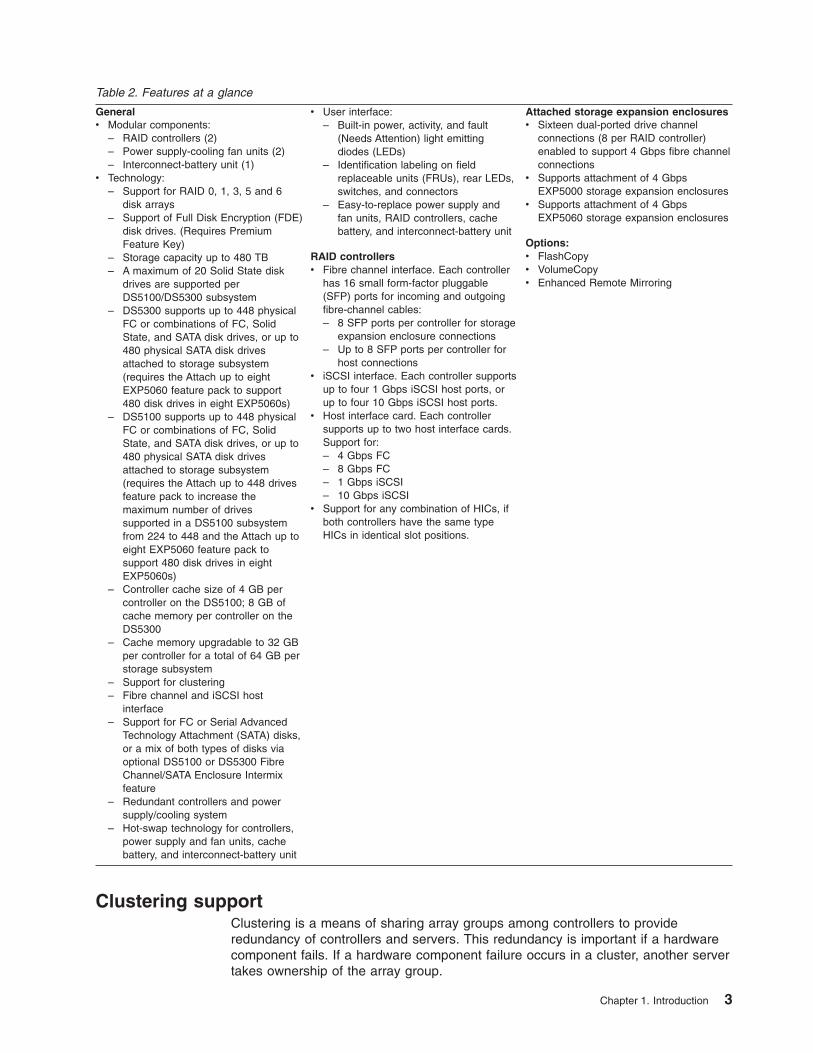
Table 2. Features at a glance
Generalv Modular components:
– RAID controllers (2)– Power supply-cooling fan units (2)– Interconnect-battery unit (1)
v Technology:– Support for RAID 0, 1, 3, 5 and 6
disk arrays– Support of Full Disk Encryption (FDE)
disk drives. (Requires PremiumFeature Key)
– Storage capacity up to 480 TB– A maximum of 20 Solid State disk
drives are supported perDS5100/DS5300 subsystem
– DS5300 supports up to 448 physicalFC or combinations of FC, SolidState, and SATA disk drives, or up to480 physical SATA disk drivesattached to storage subsystem(requires the Attach up to eightEXP5060 feature pack to support480 disk drives in eight EXP5060s)
– DS5100 supports up to 448 physicalFC or combinations of FC, SolidState, and SATA disk drives, or up to480 physical SATA disk drivesattached to storage subsystem(requires the Attach up to 448 drivesfeature pack to increase themaximum number of drivessupported in a DS5100 subsystemfrom 224 to 448 and the Attach up toeight EXP5060 feature pack tosupport 480 disk drives in eightEXP5060s)
– Controller cache size of 4 GB percontroller on the DS5100; 8 GB ofcache memory per controller on theDS5300
– Cache memory upgradable to 32 GBper controller for a total of 64 GB perstorage subsystem
– Support for clustering– Fibre channel and iSCSI host
interface– Support for FC or Serial Advanced
Technology Attachment (SATA) disks,or a mix of both types of disks viaoptional DS5100 or DS5300 FibreChannel/SATA Enclosure Intermixfeature
– Redundant controllers and powersupply/cooling system
– Hot-swap technology for controllers,power supply and fan units, cachebattery, and interconnect-battery unit
v User interface:– Built-in power, activity, and fault
(Needs Attention) light emittingdiodes (LEDs)
– Identification labeling on fieldreplaceable units (FRUs), rear LEDs,switches, and connectors
– Easy-to-replace power supply andfan units, RAID controllers, cachebattery, and interconnect-battery unit
RAID controllersv Fibre channel interface. Each controller
has 16 small form-factor pluggable(SFP) ports for incoming and outgoingfibre-channel cables:– 8 SFP ports per controller for storage
expansion enclosure connections– Up to 8 SFP ports per controller for
host connectionsv iSCSI interface. Each controller supports
up to four 1 Gbps iSCSI host ports, orup to four 10 Gbps iSCSI host ports.
v Host interface card. Each controllersupports up to two host interface cards.Support for:– 4 Gbps FC– 8 Gbps FC– 1 Gbps iSCSI– 10 Gbps iSCSI
v Support for any combination of HICs, ifboth controllers have the same typeHICs in identical slot positions.
Attached storage expansion enclosuresv Sixteen dual-ported drive channel
connections (8 per RAID controller)enabled to support 4 Gbps fibre channelconnections
v Supports attachment of 4 GbpsEXP5000 storage expansion enclosures
v Supports attachment of 4 GbpsEXP5060 storage expansion enclosures
Options:v FlashCopyv VolumeCopyv Enhanced Remote Mirroring
Clustering supportClustering is a means of sharing array groups among controllers to provideredundancy of controllers and servers. This redundancy is important if a hardwarecomponent fails. If a hardware component failure occurs in a cluster, another servertakes ownership of the array group.
Chapter 1. Introduction 3
Clustering requires software specific to your operating system. For more informationabout clustering, see www.ibm.com/servers/storage/disk/ds4000/interop-matrix.html.
Inventory checklistAfter you unpack the DS5100 or DS5300, verify that you have the following items.See “Storage subsystem components” on page 7 for the locations of hardwarecomponents on the DS5100 or DS5300.
Note: Depending on your DS5100 or DS5300 order, your shipping box mightcontain additional materials not listed in the following checklist. Review theinventory checklist included in the DS5100 or DS5300 shipping box for anyadditional parts, and use that checklist in combination with the followinginformation.
v Hardware
– One DS5100 or DS5300 bezel (front cover)
– Two RAID controllers (shipped installed in the DS5100 or DS5300)
– Two power supply and fan units (shipped installed in the DS5100 or DS5300)
– One interconnect-battery unit with two cache-backup battery packs (shippedinstalled in the DS5100 or DS5300)
– Two line cord jumpers
Line cord jumpers are power cables with an IEC C13 plug on one end and anIEC C14 plug on the other end that are used to connect the DS5100 orDS5300 RAID controller units to the IBM-certified rack power distribution units(PDUs) installed in the rack cabinet.
– Sixteen 4 Gbps SFP modules (These SFP modules are already installed inthe DS5100 or DS5300 drive ports.)
– Depending on the number and the type of host interface cards purchased, upto sixteen 4 Gbps SFP or 8 Gbps SFP, or up to eight 10 Gbps SFP+ moduleswill also be shipped installed in the host interface cards.
– One rack-mounting hardware kit, including:
- Two rails (right and left assemblies)
- Eight M5 black hex-head screws
– Wrap plug and coupler kit
Use the wrap plug and coupler kit for FC link diagnostics. See the IBMSystem Storage Problem Determination Guide for more information.
Attention: The DS5100 or DS5300 Storage Subsystem does not ship withregion-specific power cords. You must obtain the IBM-approved power cords foryour region. See Appendix E, “Power cords,” on page 271 for the IBM-approvedpower cords for your region.
v Software and documentation
– Host software attachment kit
Depending on your order, your DS5100 or DS5300 ships with either theMicrosoft Windows host software attachment kit or with your choice of hostsoftware kits (Windows, AIX®, Linux, Mac OS, SUN Solaris, HP-UX, Linux onPOWER®, or VMware). The host software kit grants you permission to attachhost servers using the appropriate operating system to the DS5100 orDS5300. The kit includes a DS Storage Manager Support DVD that has theappropriate IBM DS Storage Manager host software. The DVD also containsincludes firmware, online help, and publications in Adobe Acrobat Portable
4 IBM System Storage DS5100 or DS5300 Storage Subsystem: Installation, User’s, and Maintenance Guide

Document Format (PDF). (For a list of available IBM DS5100 or DS5300publications, see Appendix A, “Additional System Storage DS documentation,”on page 245.)
If you order more than one host software kit, the additional kits may also beshipped in the DS5100 or DS5300 shipping box.
– A storage partition premium feature activation kit based on your order.
– IBM System Storage DS5100 or DS5300 Storage Subsystems Installation,User's, and Maintenance Guide
– IBM System Storage Quick Start Guide for the DS5100 or DS5300
– IBM Safety Information
– IBM License Agreement
– Statement of Limited Warranty
If an item is missing or damaged, contact your IBM reseller or your IBM marketingrepresentative.
If you have not already done so, record your storage subsystem serial number,machine type and model number, and RAID controller MAC addresses inAppendix B, “Records,” on page 257. The serial number, machine type, and modelnumber are located on top of the DS5100 or DS5300. The MAC addresses arelocated near the Ethernet ports on each RAID controller, as shown in Figure 148 onpage 258. You may not be able to easily access this information after you install theDS5100 or DS5300.
Rack mounting templates for installing the support rails are provided in thisdocument in Appendix C, “Rack mounting templates,” on page 259.
To connect your DS5100 or DS5300 to other devices, use the following options:
v IBM SFP module
v IBM LC-LC fibre-channel cable
v IBM LC-SC fibre-channel cable (for host-side connections only)
Note: You might need to order these options separately.
Receiving product updates and support notificationsBe sure to download the latest versions of the following packages at the time ofinitial installation and when product updates become available:
v DS Storage Manager host software
v DS5100 and DS5300 storage subsystem controller firmware
v DS5100 and DS5300 drive expansion enclosure ESM firmware
v Drive firmware
ImportantKeep your system up-to-date with the latest firmware and other productupdates by subscribing to receive support notifications.
For more information about how to register for support notifications, seehttp://www.ibm.com/systems/support and click My notifications.
Chapter 1. Introduction 5

Also, see http://www.ibm.com/systems/support/storage/disk and check the StayInformed section.
Best practices guidelinesTo ensure optimal operation of your system, always follow these best practicesguidelines:
v Ensure that your system is in an optimal state before you shut it down. Neverturn the power off if any Needs Attention LED is lit; be sure to resolve any errorconditions before you shut down the system.
v Back up the data on your storage drives periodically.
v Collect All Support Data from the storage subsystem periodically and after anychanges in the subsystem configuration.
v To maintain power redundancy, plug the DS5100 or DS5300 right and left RAIDcontroller units into two independent external power circuits through acdistribution units inside a rack cabinet or directly into external receptacles.Similarly, the right and left power supplies of the DS5100 or DS5300 storageexpansion enclosures attached to the DS5100 or DS5300 should be plugged intothe same two independent external power circuits as the DS5100 or DS5300.This ensures that the DS5100 or DS5300 and all its attached storage expansionenclosures will have power in the event that only one power circuit is available.In addition, having all the right or all the left power cables plug into the samepower circuit enables the DS5100 or DS5300 devices in the configuration topower on simultaneously during an unattended restoration of power. SeeFigure 102 on page 150 for an example of redundant power connections.
Note: Do not overload the circuits that power your storage subsystem andstorage expansion enclosures. Use additional pairs of power distributionunits (PDUs) if necessary. Refer to the Installation, User's, andMaintenance Guide for your storage expansion enclosures for informationon storage expansion enclosure power requirements. Contact your IBMservice representative for additional information if needed.
v Before any planned system shutdown or after any system additions, removals, ormodifications (including firmware updates, logical drive creations, storagepartitioning definitions, hardware changes, and so on), complete the followingtasks:
1. Save the storage subsystem profile
2. Save the storage subsystem configuration
3. Save the Collect All Support Data (CASD)
Make sure that you save the files in a location other than in the logical drives thatwere created for the storage subsystem.
For more information on how to complete these tasks, check the DS StorageManager online help or the Storage Manager guide for your operating system.
v During any maintenance or attended power-up procedure, carefully follow thepower-up sequence listed in “Turning on the storage subsystem” on page 155.Check that each component of the subsystem is powered-on in the proper orderduring this entire power-up procedure to ensure the controller will be able tooptimally access all of your storage subsystems.
v The storage subsystem supports simultaneous power-up to the systemcomponents; however, you should always follow the power-up sequence listed in“Turning on the storage subsystem” on page 155 during any attended power-upprocedure.
6 IBM System Storage DS5100 or DS5300 Storage Subsystem: Installation, User’s, and Maintenance Guide

v A storage subsystem in an optimal state should recover automatically from anunexpected shutdown and unattended simultaneous restoration of power tosystem components. After power is restored, call IBM support if any of thefollowing conditions occur:
– The storage subsystem logical drives and arrays are not displayed in the DSStorage Manager graphical user interface (GUI).
– The storage subsystem logical drives and arrays do not come online.
– The storage subsystem logical drives and arrays seem to be degraded.
Storage subsystem componentsThe DS5100 or DS5300 storage subsystem directs and manages the I/O activitybetween a host and the drives in a RAID array. Figure 1 shows the DS5100 orDS5300 with front bezel in place.
Note: The illustrations in this document might differ slightly from your hardware.
The storage subsystem comprises has five components. The components, and thequantity of each component in the storage subsystem, are the following:
v RAID controllers (two)
v Power supply and fan units (two)
v Interconnect-battery unit (one)
The power supply and fan unit and interconnect-battery unit are located behind thefront bezel. The controllers are located in the rear of the storage subsystem. Allcomponents are secured in the storage subsystem by quick release latches,enabling each component to be removed by disengaging the latch and sliding thecomponent from the storage subsystem chassis. Figure 2 on page 8 shows thepositions of the components in the DS5100 or DS5300.
ds50008
Figure 1. DS5100 or DS5300 Storage Subsystem
Chapter 1. Introduction 7
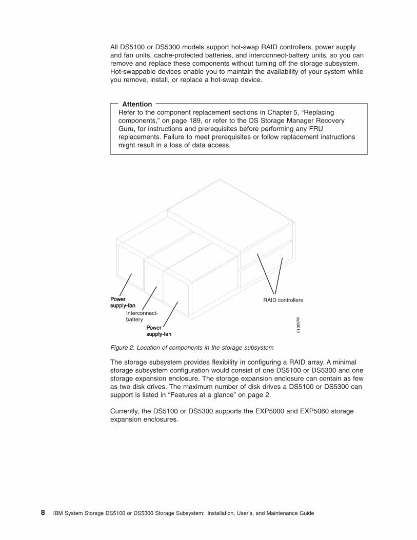
All DS5100 or DS5300 models support hot-swap RAID controllers, power supplyand fan units, cache-protected batteries, and interconnect-battery units, so you canremove and replace these components without turning off the storage subsystem.Hot-swappable devices enable you to maintain the availability of your system whileyou remove, install, or replace a hot-swap device.
AttentionRefer to the component replacement sections in Chapter 5, “Replacingcomponents,” on page 189, or refer to the DS Storage Manager RecoveryGuru, for instructions and prerequisites before performing any FRUreplacements. Failure to meet prerequisites or follow replacement instructionsmight result in a loss of data access.
The storage subsystem provides flexibility in configuring a RAID array. A minimalstorage subsystem configuration would consist of one DS5100 or DS5300 and onestorage expansion enclosure. The storage expansion enclosure can contain as fewas two disk drives. The maximum number of disk drives a DS5100 or DS5300 cansupport is listed in “Features at a glance” on page 2.
Currently, the DS5100 or DS5300 supports the EXP5000 and EXP5060 storageexpansion enclosures.
Powersupply-fan
Interconnect-battery
RAID controllersPowersupply-fanPowersupply-fan
Powersupply-fanPowersupply-fanPowersupply-fan
ds50013
Figure 2. Location of components in the storage subsystem
8 IBM System Storage DS5100 or DS5300 Storage Subsystem: Installation, User’s, and Maintenance Guide

ImportantThe EXP5000 (1818-D1A) is the storage expansion enclosure specificallydesigned for the DS5100 or DS5300 (1818-51A and 1818-53A) and along withthe EXP5060 (1818-G1A), is the storage expansion enclosure supportedbehind the DS5100 or DS5300 with the exception noted below. This is acritical requirement due to the following:
v Only the EXP5000 will be supported with future enhancements of theDS5100 or DS5300 such as disk encryption and solid stated disks.
v Only the EXP5000 will provide clients consistent warranty and supportterms and conditions (including geo-specific, SSR installation and supportfor the entire system, and code upgrades within the initial warranty period).
The only exception is that for client investment protection, existing EXP810scan be migrated from currently installed DS4700s or DS4800s to attach to aDS5100 or DS5300. An RPQ approval is required for support of all migrationconfigurations. With approved migration of EXP810s to a DS5100 or DS5300,special consideration needs to be made as to proper firmware levels (asdocumented in the DS4000/DS5000 Hard Drive and Storage ExpansionEnclosure Installation and Migration Guide), and careful coordination ofdifferences in warranty and maintenance terms that will affect your customer.RPQ requests can be submitted through the normal RPQ request process.
Purchase of new EXP810s to attach to DS5100 or DS5300 will not besupported or configurable in eConfig.
Note: Disk drive modules that can be ordered in bulk or individually ascustomer installable parts for the EXP810 are not supported for use inthe EXP5000. Only disk drive modules ordered as feature codes of1818-D1A, and delivered pre-installed in the EXP5000, or asSSR-installable upgrades to EXP5000s will be supported.
See Table 3 for the maximum number of storage expansion enclosures that can beattached to the DS5100 or DS5300 by storage expansion enclosure type.
Table 3. Maximum number of storage expansion enclosures
Enclosure type
Maximum number of enclosures ina redundant DS5100 or DS5300drive channel pair
Maximum number of enclosures ina DS5100 or DS5300 subsystem
EXP5000 7 28
Chapter 1. Introduction 9

Table 3. Maximum number of storage expansion enclosures (continued)
Enclosure type
Maximum number of enclosures ina redundant DS5100 or DS5300drive channel pair
Maximum number of enclosures ina DS5100 or DS5300 subsystem
EXP5060
Notes:
1. Requires firmware version7.60.13.05, or higher.
2. Maximum configuration requiresthe Attach up to eight EXP5060feature.
3. The Attach up to eight EXP5060feature activation requires IO tothe subsystem be quiesce.
4. The Attach up to eight EXP5060feature pack does not support anyother type of enclosure besidesthe EXP5060. Disconnect anyEXP5000/EXP810 expansionenclosures before activating theAttach up to eight EXP5060feature pack.
2 8
EXP5000 and EXP5060 1 EXP50603 EXP5000
Varies depending on the number ofEXP5060 and EXP5000 expansionenclosures that are connected toeach of the four DS5100/DS5300drive channels.
ControllersThe DS5100 or DS5300 has two RAID controllers. Both controllers are identical andinterchangeable. The controllers install from the rear of the storage subsystem. Theupper controller is controller A; the lower controller is controller B. All connections tothe hosts and the drives in the storage configuration are through the controllers.Figure 3 on page 11 shows the controllers in the DS5100 or DS5300.
Note: Although both RAID controller units (A and B) in the DS5100 or DS5300 areidentical, they are seated in the DS5100 or DS5300 chassis in oppositeorientations. As shown in Figure 3 on page 11, the controller units must beinserted in the DS5100 or DS5300 so that the latches of each controller areon the exterior of the DS5100 or DS5300 chassis. The latches on controllerA line up with the top side of the DS5100 or DS5300 chassis; the latches oncontroller B line up with the bottom side of the DS5100 or DS5300 chassis.
10 IBM System Storage DS5100 or DS5300 Storage Subsystem: Installation, User’s, and Maintenance Guide

Information about the condition of the controllers is conveyed by indicator LEDs onthe back of each controller. (“RAID controller LEDs” on page 169 identifies theindicator LEDs on the RAID controller and explains the conditions that each LEDindicates.)
Controller cable connectionsEach controller provides the following connections:
v Four dual-ported fibre channel drive channels
v Up to eight single-ported Fibre Channel host channels, up to four RJ-45 or SFP+iSCSI host ports, or four single-ported FC host channels and two RJ-45 or SFP+iSCSI host ports, depending on the types of host interface cards (HICs) installedin the controllers.
v Two RJ-45 Management Ethernet ports.
v One RS-232 serial port.
v AC power.
Figure 4 on page 12, Figure 5 on page 12, and Figure 6 on page 13 identify theconnectors on the back of each controller.
Controller A
Controller B
Controller A latches
Controller B latches
ds50014
Figure 3. Controllers in the storage subsystem
Chapter 1. Introduction 11

RS-232serial portEthernet portsDual-ported
drive channels
ACpower
Controller A
Strain-reliefclamp
ACpowerStrain-relief
clampEthernet portsRS-232serial port Dual-ported
drive channels
Controller B
Fibre Channel host ports
Fibre Channel host ports
Figure 4. Fibre Channel Controller connections
iSCSI host channels
RS-232serial port
Ethernet portsDual-porteddrive channels
ACpower
Controller A
Strain-reliefclamp
ACpower
Strain-reliefclampEthernet ports
RS-232serial port
Dual-porteddrive channels
Controller B
Figure 5. 1 Gbps iSCSI Controller connections
12 IBM System Storage DS5100 or DS5300 Storage Subsystem: Installation, User’s, and Maintenance Guide

Dual-ported drive channelsEach controller has four drive channels; each drive channel has two fibrechannel ports. The drive channels are used to connect storage expansionenclosures to the RAID controllers on the DS5100 or DS5300.
Attention: Before you power on the DS5100 or DS5300, the storagesubsystem must be cabled to at least one storage expansion enclosurepopulated with the minimum number of drives for the storage expansionenclosure. Otherwise, the DS5100 or DS5300 controllers do notsuccessfully complete the power-on process and operate optimally.
Two drive channels (one from each controller) are used to form a redundantdrive channel pair. Each drive channel pair supports up to a maximum of112 drives in seven IBM DS5100 or DS5300 storage expansion enclosures.(See Table 3 on page 9 for more information.)
Host channelsEach DS5100 and DS5300 controller supports two host interface cards. TheDS5100 or DS5300 controller supports 4 Gbps and 8 Gbps FC, 1 GbpsiSCSI, or 10 Gbps iSCSI host interface cards. With the exception that the 1Gbps iSCSI and 10 Gbps iSCSI HICs must not be installed in the samestorage subsystem, these cards can be mixed within a controller providedthat the same type of card is installed in the same host interface card slot inboth controllers. The 4 Gbps and 8 Gbps FC host interface cards containfour single-port host fibre channel ports per card for a maximum of eight FCports per controller. The 1 Gbps and 10 Gbps iSCSI host interface cardscontain two two-port iSCSI ports for a maximum of four iSCSI ports percontroller.
Attention:
1. If there is only one host interface card (HIC) per controller, install theHIC in slot 1 or the controller will lock down during the boot process.
2. The controller will enter the lockdown state if the 1 Gbps and 10 GbpsHIC are installed in the same controller.
10 Gbps iSCSI host channels
RS-232serial portEthernet ports
Dual-porteddrive channels
ACpower
Controller A
Strain-reliefclamp
ACpower
Strain-reliefclamp
Ethernet portsRS-232serial port
Dual-porteddrive channels
Controller B
d5xi0
001
Figure 6. 10 Gbps iSCSI Controller connections
Chapter 1. Introduction 13
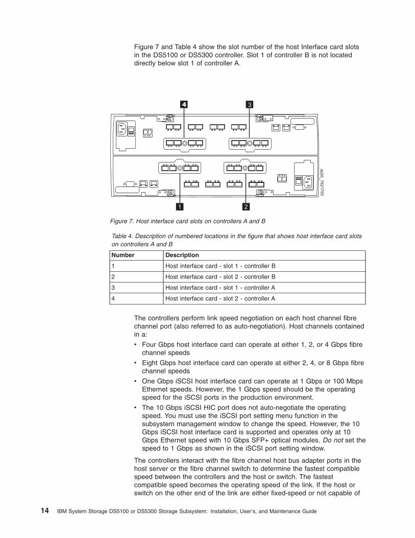
Figure 7 and Table 4 show the slot number of the host Interface card slotsin the DS5100 or DS5300 controller. Slot 1 of controller B is not locateddirectly below slot 1 of controller A.
Table 4. Description of numbered locations in the figure that shows host interface card slotson controllers A and B
Number Description
1 Host interface card - slot 1 - controller B
2 Host interface card - slot 2 - controller B
3 Host interface card - slot 1 - controller A
4 Host interface card - slot 2 - controller A
The controllers perform link speed negotiation on each host channel fibrechannel port (also referred to as auto-negotiation). Host channels containedin a:
v Four Gbps host interface card can operate at either 1, 2, or 4 Gbps fibrechannel speeds
v Eight Gbps host interface card can operate at either 2, 4, or 8 Gbps fibrechannel speeds
v One Gbps iSCSI host interface card can operate at 1 Gbps or 100 MbpsEthernet speeds. However, the 1 Gbps speed should be the operatingspeed for the iSCSI ports in the production environment.
v The 10 Gbps iSCSI HIC port does not auto-negotiate the operatingspeed. You must use the iSCSI port setting menu function in thesubsystem management window to change the speed. However, the 10Gbps iSCSI host interface card is supported and operates only at 10Gbps Ethernet speed with 10 Gbps SFP+ optical modules. Do not set thespeed to 1 Gbps as shown in the iSCSI port setting window.
The controllers interact with the fibre channel host bus adapter ports in thehost server or the fibre channel switch to determine the fastest compatiblespeed between the controllers and the host or switch. The fastestcompatible speed becomes the operating speed of the link. If the host orswitch on the other end of the link are either fixed-speed or not capable of
3
1 2
ds5
0_
76
21
70
5
4
Figure 7. Host interface card slots on controllers A and B
14 IBM System Storage DS5100 or DS5300 Storage Subsystem: Installation, User’s, and Maintenance Guide

negotiating, the controllers automatically detect the operating speed of theother host or switch and set the controller link speed accordingly. Linkspeed negotiation for a given host channel is limited to link speedssupported by the small form-factor pluggable (SFP) module on that channel.
Similarly, the controllers interact with the 1 Gbps iSCSI host bus adapterports in the host server or the Ethernet switch to determine the fastestcompatible speed between the controllers and the host or switch. Thefastest compatible speed becomes the operating speed of the link. If thehost or switch on the other end of the link are either fixed-speed or notcapable of negotiating, the controllers automatically detect the operatingspeed of the other host or switch and set the controller link speedaccordingly. However, the 10 Gbps host port does not negotiate for theoptimal link speed. It must be manually configured to operate at 10 Gbpsspeed using the iSCSI port setting menu function in the subsystemmanagement window. Table 5 shows the default IP addresses of the iSCSIhost ports.
The iSCSI ports support Internet Storage Naming Service (iSNS) inMicrosoft Windows environment and Challenge Handshake AuthenticationProtocol (CHAP).
The controllers enter into auto-negotiation at these points in time:
v Start-of-day
v Detection of a link-up event after a previous link-down event
If the auto-negotiation process fails, the controllers consider the link to bedown until negotiation is again attempted at one of these points in time.
Ethernet portsThe Ethernet connections provide for out-of-band managementconfigurations to a host. The Ethernet ports are used for an RJ-4510BASE-T or 100BASE-T Ethernet connection to each controller. Use theEthernet connection to directly manage the DS5100 or DS5300.
Use one Ethernet port for daily management of the DS5100 or DS5300.Reserve the other port for use by service personnel or for subsystemmonitoring hardware that may be available in the future.
The two Ethernet ports must be connected into networks with two separatesubnet masks. Otherwise, the following Recovery Guru error will begenerated:Ethernet Configuration conflict. Both Ethernet ports for a givenDS5100 or DS5300 controller have been assigned IP addressesfrom the same subnet.
You can also make out-of-band management connections to the DS5100 orDS5300 controllers using the default IP addresses. See Table 5 for thedefault IP addresses and subnet masks for the management ports andiSCSI ports (if installed). See “Setting up IP addresses for DS5100 orDS5300 storage controllers” on page 16 for more information.
Table 5. Default IP addresses and subnet masks
Port IP address Subnet Mask
Controller A Management port1
192.168.128.101 255.255.255.0
Controller A Management port2
192.168.129.101 255.255.255.0
Chapter 1. Introduction 15

Table 5. Default IP addresses and subnet masks (continued)
Port IP address Subnet Mask
Controller B Managementport 1
192.168.128.102 255.255.255.0
Controller B Managementport 2
192.168.129.102 255.255.255.0
Controller A iSCSI port 1 192.168.130.101 255.255.255.0
Controller A iSCSI port 2 192.168.131.101 255.255.255.0
Controller A iSCSI port 3 192.168.132.101 255.255.255.0
Controller A iSCSI port 4 192.168.133.101 255.255.255.0
Controller B iSCSI port 1 192.168.130.102 255.255.255.0
Controller B iSCSI port 2 192.168.131.102 255.255.255.0
Controller B iSCSI port 3 192.168.132.102 255.255.255.0
Controller B iSCSI port 4 192.168.133.102 255.255.255.0
RS-232 serial portThe RS-232 serial connection provides a diagnostic port for use by servicepersonnel only to perform diagnostic operations on the RAID controllers.
Attention: Incorrect use of the serial port can result in loss of data accessand, in some cases, in loss of data. Do not make any connections to theserial port unless you do so under the direct guidance of IBM supportpersonnel.
Note: The maximum baud rate is 115 200 bps. The default baud ratesetting from the factory is 38 400 bps.
Setting up IP addresses for DS5100 or DS5300 storagecontrollersAfter you install DS Storage Manager (as described in the DS Storage ManagerInstallation and Support Guide for your host operating system), complete one of thefollowing procedures to set up IP addresses:
v “Steps for setting up the DHCP/BOOTP server and network”
v “Steps for assigning static TCP/IP addresses to the controllers with the DSStorage Manager client host software” on page 17
v “Steps for assigning static TCP/IP addresses to the controllers with the controllerserial port” on page 18
Steps for setting up the DHCP/BOOTP server and network: To complete thisprocedure, you must have the following components:
v A DHCP or BOOTP server
v A network management station (NMS) for Simple Network Management Protocol(SNMP) traps
v A host that is connected to a storage subsystem through a fibre-channel I/O path
v A management station that is connected by an Ethernet cable to the storagesubsystem controllers
Note: You can avoid DHCP/BOOTP server and network tasks either by using thedefault controller IP addresses, or by assigning static IP addresses to thecontroller, as described in the next section.
Complete the following steps to set up the DHCP/BOOTP server and network:
16 IBM System Storage DS5100 or DS5300 Storage Subsystem: Installation, User’s, and Maintenance Guide

1. Get the MAC address from each controller blade.
2. Complete whichever of the following steps is appropriate for your server:
v On a DHCP server, create a DHCP record for each of the MAC addresses.Set the lease duration to the longest time possible.
v On a BOOTP server, edit the bootptab file to add in the entries that associatethe MAC address tab with the TCP/IP address.
3. Connect the storage subsystem Ethernet ports to the network.
4. Boot the storage subsystem.
The DHCP server automatically assigns new IP addresses to the controller Ethernetport.
Steps for assigning static TCP/IP addresses to the controllers with the DSStorage Manager client host software: To complete this procedure, you musthave the following components:
v A host that is connected to a storage subsystem through a fibre-channel I/O path
v A management station that is connected by an Ethernet cable to the storagesubsystem controllers
Complete the following steps to assign static TCP/IP addresses to the DS5100 orDS5300 storage subsystem controllers, using default TCP/IP addresses that areassigned to the DS5100 or DS5300 storage subsystem controllers duringmanufacturing:
1. Make a direct management connection to the DS5100 or DS5300, using thedefault TCP/IP addresses:
v Controller A: 192.168.128.101
v Controller B: 192.168.128.102
v Subnet Mask: 255.255.255.0
Note: For a DS5100 or DS5300 that has two Ethernet ports per controller, usethe Ethernet port that is labeled #1.
2. Start the DS Storage Manager client software. The Enterprise Managementwindow opens.
3. Add the DS5100 or DS5300 to the Enterprise Management domain using thedefault IP addresses.
4. In the Enterprise Management window, click on the name of the default storagesubsystem. The Subsystem Management window opens.
5. In the Subsystem Management window, right-click the controller icon and selectChange —> Network Configuration in the pull-down menu. The ChangeNetwork Configuration window opens.
6. In the Change Network Configuration window, click on the Controller A andController B tabs and type the new TCP/IP addresses in their appropriate fields.Click OK.
7. Close the Subsystem Management window, wait at least five minutes, thendelete the default storage subsystem entry in the Enterprise Managementwindow. The default storage subsystem entry still displays, but shows an“unresponsive” icon.
8. If applicable, change the IP address of the Ethernet port in the managementstation to a value that is on the same TCP/IP subnet as the controller Ethernetport IP addresses that you just assigned. Exit DS Storage Manager, thenrestart.
Chapter 1. Introduction 17

9. Add a new storage subsystem entry in the Enterprise Management window,using the new assigned IP addresses.
Steps for assigning static TCP/IP addresses to the controllers with thecontroller serial port: To complete this procedure, you must have the followingcomponents:
v A null modem cable with DB-9 female connectors on both ends, used to connectthe host serial port to the controller serial port.
v A terminal emulation software application, such as Procomm or MicrosoftWindows Hyperterm, installed in the host system.
Notes:
1. The terminal session setting must have these values: 38400 BAUD; 8 databits; 1 stop bit; no parity.
2. If the controller BAUD rate setting is different from the terminal setting, senda "break" character to cause the controller to switch to the next availableBAUD rate setting. Repeat sending the "break" character until the "Pressspace to set the BAUD rate" message is displayed.
v Controller firmware version 7.77.xx.xx or higher and its associated NVSRAM filesinstalled.
Complete the following steps to view and assign new IP address to the controllermanagement port:
1. Press Enter. If this character (->) is displayed, type Exit and press Enter.Otherwise, continue to next step.
2. In the terminal emulator session, send the "break" character (For example, useCNTL+BREAK for Microsoft Windows Hyperterm or ALT+B for Procomm).
3. Enter the uppercase letter S and press Enter when the following message isdisplayed: Press within 5 seconds: <S> for Service Interface, <BREAK> forbaud rate
4. Enter the password DSStorage (case sensitive) within 60 seconds of when thismessage is displayed: Enter Password to access Service Interface (60 sectimeout).
Note: If the controller does not have controller firmware version 7.77.xx.xx orhigher and its associated NVSRAM files installed, this password will notbe accepted, and you must follow one of the two methods to change theIP configuration of controller Ethernet ports that are described in the“Steps for assigning static TCP/IP addresses to the controllers with theDS Storage Manager client host software” on page 17.
5. When the following menu is displayed, enter 1 or 2 to display or change IPconfiguration, respectively.Service Interface Main Menu==============================1) Display IP Configuration2) Change IP Configuration3) Reset Storage Array Administrator PasswordQ) Quit Menu
If option 2 is chosen, follow the prompt to set the IP configuration for the portthat you selected. You must reboot the controller for the settings to take effect.
18 IBM System Storage DS5100 or DS5300 Storage Subsystem: Installation, User’s, and Maintenance Guide
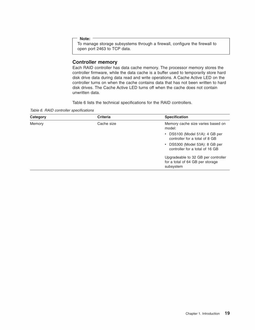
Note:To manage storage subsystems through a firewall, configure the firewall toopen port 2463 to TCP data.
Controller memoryEach RAID controller has data cache memory. The processor memory stores thecontroller firmware, while the data cache is a buffer used to temporarily store harddisk drive data during data read and write operations. A Cache Active LED on thecontroller turns on when the cache contains data that has not been written to harddisk drives. The Cache Active LED turns off when the cache does not containunwritten data.
Table 6 lists the technical specifications for the RAID controllers.
Table 6. RAID controller specifications
Category Criteria Specification
Memory Cache size Memory cache size varies based onmodel:
v DS5100 (Model 51A): 4 GB percontroller for a total of 8 GB
v DS5300 (Model 53A): 8 GB percontroller for a total of 16 GB
Upgradeable to 32 GB per controllerfor a total of 64 GB per storagesubsystem
Chapter 1. Introduction 19

Table 6. RAID controller specifications (continued)
Category Criteria Specification
Interface Fibre channel or iSCSI host port Two host interface cards per controllerfor a total of 8 fibre channel host portsor four iSCSI host ports per controller.Support for:
v Two 4 Gbps FC host interfacecards per controller
v Two 8 Gbps FC host interfacecards per controller
v One 4 Gbps FC host interface cardand one 8 Gbps FC host interfacecard per controller.
v Two 1 Gbps iSCSI host interfacecards per controller.
v Two 10 Gbps iSCSI host interfacecards per controller.
v Any combination of 4 Gbps FC, 8Gbps FC, or either 1 Gbps iSCSI or10 Gbps iSCSI host interface cards.Important: Do not intermix a 1Gbps and a 10 Gbps iSCSI hostinterface card in the same storagesubsystem. When mixing 1 GbpsiSCSI or 10 Gbps iSCSI, 4 GbpsFC, and 8 Gbps FC host interfacecards in a controller, you must usethe same combination in the samehost interface card slots in the othercontroller. For example, in controllerA, if host interface card slot 1contains a 4 Gbps host interfacecard and host interface card slot 2contains an 8 Gbps host interfacecard, then host interface card slot 1in controller B must contain a 4Gbps host interface card and hostinterface card slot 2 must containan 8 Gbps host interface card.Otherwise, the controller is in thelockdown state during the bootprocess.
Two Ethernet ports per controller (forout-of-band management)
Fibre channel drive expansion port 8 fiber-optic ports per controllerNote: Each DS5100 or DS5300controller drive channel has two ports.There are four drive channels perDS5100 or DS5300 controller.
20 IBM System Storage DS5100 or DS5300 Storage Subsystem: Installation, User’s, and Maintenance Guide

Table 6. RAID controller specifications (continued)
Category Criteria Specification
Storage expansion enclosure support Redundant drive channel pairs 4 per controller
Maximum number of drives perredundant drive channel pair
112 drives per redundant drivechannel pair (Seven storageexpansion enclosures with 16 driveseach). See Table 3 on page 9.
Maximum number of drives supportedby one DS5100
224 drives standard. Supports up to480 drives with purchase of the Attachup to 448 drives feature pack and theAttach up to eight EXP5060 featurepack.
A premium feature is available toprovide support for up to 448 drives.
Maximum number of drives supportedby one DS5300
448 drives standard. Supports up to480 drives with the purchase of theAttached up to eight EXP5060 featurepack.
Data transfer rates Fibre channel host Up to 8 Gb/sec maximum when 8Gbps FC host interface cards areused.
v Supports 1, 2, and 4 Gbpsauto-negotiated FC speeds whenusing 4 Gbps host interface cards
v Supports 2, 4, and 8 Gbpsauto-negotiated FC speeds whenusing 8 Gbps host interface cards
iSCSI host 1 Gb/sec maximum 10GBASE-SR)when 1 Gbps iSCSI HICs are used.
10 Gb/sec maximum when 10 GbpsiSCSI HICs are used.
Fibre channel drives 4 Gbps
SATA drives 3 Gbps
Solid State Drives 4Gbps
Ethernet management ports 10BASE-T
100BASE-T
1000BASE-T
Power supply and fan unitsThe DS5100 or DS5300 have two power supply and fan units. Each power supplyand fan unit contains a power supply, a fan, and a battery charger. Each powersupply provides power to the controllers by converting incoming ac voltage to theappropriate dc voltages. If one power supply and fan unit is turned off ormalfunctions, the remaining power supply and fan unit can maintain electrical powerand cooling to the storage subsystem.
Note: Contact IBM for information about possible future dc-to-dc power supplysupport.
Chapter 1. Introduction 21

Install the power supply and fan units from the front of the storage subsystem.Figure 8 shows how a power supply and fan unit slides into the storage subsystem.The levers that secure the left power supply and fan unit into the storagesubsystem are shown in the released position. The levers that secure the rightpower supply and fan unit into the storage subsystem are shown in the latchedposition.
Note: Although both power supply and fan units in the DS5100 or DS5300 chassisare identical, they are seated in the DS5100 or DS5300 chassis in oppositeorientations. The left and right power supply and fan units are installed sothat the LED column of each power supply and fan unit is located towardsthe interior of the DS5100 or DS5300, along the side of theinterconnect-battery unit.
Information about the condition of the power supplies, fans, and battery charger isconveyed by indicator lights (LEDs) on the front of each of the power supply andfan units and on the interconnect-battery unit. You must remove the front bezel tosee the LEDs. (“Power supply and fan unit LEDs” on page 175 identifies theindicator LEDs on a power supply and fan unit and explains the conditions thateach LED indicates.)
Note: The order of the LEDs on the power supply and fan unit is differentdepending on whether the power supply and fan unit is installed in the left orright bay.
In the DS5100 or DS5300, the right power supply and fan unit is linked to controllerA, and the left power supply and fan unit is linked to controller B. To increaseprotection against power loss, always make sure that both power supply and fanunits are operational.
Interconnect-battery unitThe interconnect-battery unit is a removable midplane that provides cross-coupledsignal connection between the controllers. The control output from each controller isconnected to the control input in the alternate controller. An audible alarm ismounted on the interconnect-battery unit display board. A mute switch for theaudible alarm is also mounted on the same board. The interconnect-battery unitalso provides the electrical communication path between the power supply and fan
Latch
LatchPower supply andfan units
Levers inreleasedposition
Levers inlatchedposition
ds50016
Figure 8. Power supply and fan unit
22 IBM System Storage DS5100 or DS5300 Storage Subsystem: Installation, User’s, and Maintenance Guide

units and allows their power supplies to load-share and to charge the cache-backupbattery packs. There are two cache-backup battery packs mounted inside theinterconnect-battery unit.
Attention: Because the interconnect-battery unit provides electrical signalconnections between the controllers, removing the interconnect-battery unitinterrupts the communications between the controller units in the DS5100 orDS5300, resulting in a loss of communication between controllers A and B. Dataaccess is limited to only controller A when the interconnect-battery unit is removed.Controller B is in an offline state while controller A performs all controller operations.To prevent any problems as a result of this condition, controller B must be placedoffline before you remove the interconnect-battery unit. See “Replacing theinterconnect-battery unit” on page 209 for more information. Failure to observe theinstructions and prerequisites described in “Replacing the interconnect-battery unit”on page 209 might result in a loss of data access.
Figure 9 shows how the interconnect-battery unit slides into the front of the storagesubsystem. The levers securing the interconnect-battery units to the storagesubsystem are shown in the released position.
The interconnect-battery unit contains two battery packs that maintain power for upto thirty minutes to allow the controller to flush all cache data to the USB flashmemory modules, which are installed on each controller. Each battery pack containssealed, rechargeable lithium ion batteries.
The battery chargers in the power supply and fan units perform a battery test andlearn when the storage subsystem is started and on a regularly scheduled intervalthereafter. Data caching is suspended during periods when the controllers performbattery tests and learn cycles only if the battery charge capacity drops below theminimum required charge level for backing up cache during the power down event.
Leversin releasedposition
Interconnect-battery unit
ds50017
Figure 9. Interconnect-battery unit
Chapter 1. Introduction 23

The interconnect-battery unit is hot-swappable. You can remove theinterconnect-battery unit for servicing and then reinsert it while the DS5100 orDS5300 continues to perform I/O operations.
Note: Data caching is suspended when the interconnect-battery unit is removedfrom the chassis.
AttentionNever remove the interconnect-battery unit unless directed to do so by an IBMsupport representative. Removing the interconnect-battery unit after acontroller or a power supply and fan unit has already been removed results ina loss of data access. Refer to “Replacing the interconnect-battery unit” onpage 209 for complete information about the conditions required for saferemoval of the interconnect-battery unit. Do not replace theinterconnect-battery unit without first meeting the requirements described in“Replacing the interconnect-battery unit” on page 209.
Information about the condition of the interconnect-battery unit is conveyed byindicator LEDs on the front of interconnect-battery unit. (“Interconnect-battery unitLEDs” on page 176 identifies the indicator LEDs on the interconnect-battery unitand explains the conditions that each LED indicates.)
You must remove the front bezel in order to see all of the interconnect-battery unitLEDs. With the bezel in place, only the following interconnect-battery unit LEDs arevisible:
v Power
v Overall DS5100 or DS5300 Configuration Needs Attention
v Locate/Identify
Note: The displayed order of the Overall DS5100 or DS5300 Configuration NeedsAttention and Locate/Identify LEDs on the interconnect-battery unit arereversed when the bezel is removed. See “Front bezel LEDs” on page 168and “Interconnect-battery unit LEDs” on page 176.
SFP modulesThe storage subsystem supports fiber-optic interface cables. You must install aSmall Form-factor Pluggable (SFP) module in each interface connector on thecontroller where a fibre optic cable is to be installed. Do not install an SFP in anyport that will not have a fibre optic cable attached. Additionally, it is best practicethat you remove any SFP from any port that does not have fibre optic cablesattached.
Figure 10 on page 25 shows an SFP module with fiber-optic cable. Note that theSFP module shown might look different from those shipped with your unit. Thedifferences do not affect module performance.
Attention: Currently, the DS5100 or DS5300 supports only short-wave/multimodeSFPs. In DS5100 or DS5300 configurations, you may use long-wave SFPs only infibre channel switches that connect DS5100 or DS5300s over long distances. Inaddition, there are not any visual markings to identify the maximum operatingspeeds of the SFPs aside from the option and FRU part number on the SFP label.
24 IBM System Storage DS5100 or DS5300 Storage Subsystem: Installation, User’s, and Maintenance Guide
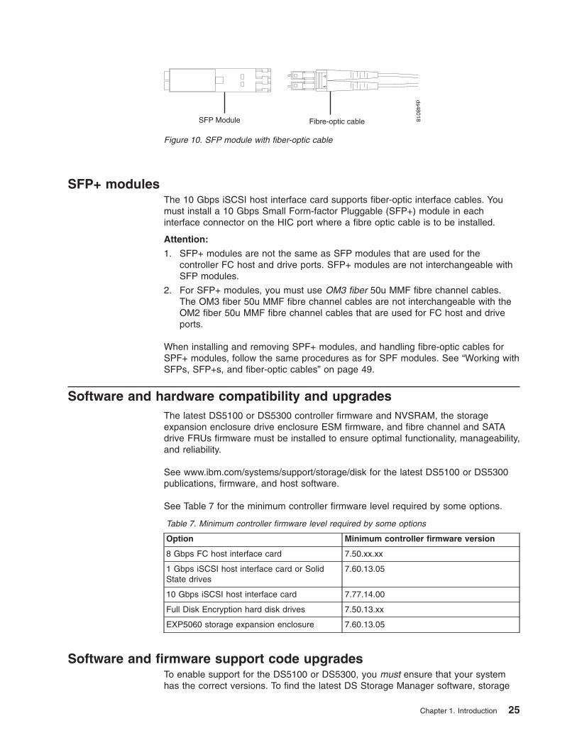
SFP+ modulesThe 10 Gbps iSCSI host interface card supports fiber-optic interface cables. Youmust install a 10 Gbps Small Form-factor Pluggable (SFP+) module in eachinterface connector on the HIC port where a fibre optic cable is to be installed.
Attention:
1. SFP+ modules are not the same as SFP modules that are used for thecontroller FC host and drive ports. SFP+ modules are not interchangeable withSFP modules.
2. For SFP+ modules, you must use OM3 fiber 50u MMF fibre channel cables.The OM3 fiber 50u MMF fibre channel cables are not interchangeable with theOM2 fiber 50u MMF fibre channel cables that are used for FC host and driveports.
When installing and removing SPF+ modules, and handling fibre-optic cables forSPF+ modules, follow the same procedures as for SPF modules. See “Working withSFPs, SFP+s, and fiber-optic cables” on page 49.
Software and hardware compatibility and upgradesThe latest DS5100 or DS5300 controller firmware and NVSRAM, the storageexpansion enclosure drive enclosure ESM firmware, and fibre channel and SATAdrive FRUs firmware must be installed to ensure optimal functionality, manageability,and reliability.
See www.ibm.com/systems/support/storage/disk for the latest DS5100 or DS5300publications, firmware, and host software.
See Table 7 for the minimum controller firmware level required by some options.
Table 7. Minimum controller firmware level required by some options
Option Minimum controller firmware version
8 Gbps FC host interface card 7.50.xx.xx
1 Gbps iSCSI host interface card or SolidState drives
7.60.13.05
10 Gbps iSCSI host interface card 7.77.14.00
Full Disk Encryption hard disk drives 7.50.13.xx
EXP5060 storage expansion enclosure 7.60.13.05
Software and firmware support code upgradesTo enable support for the DS5100 or DS5300, you must ensure that your systemhas the correct versions. To find the latest DS Storage Manager software, storage
SFP Module Fibre-optic cable
ds48018
Figure 10. SFP module with fiber-optic cable
Chapter 1. Introduction 25

subsystem controller firmware, ESM, and NVSRAM firmware, check the firmwareREADME files. See “Finding Storage Manager software, controller firmware, andREADME files” on page xxviii to learn how to access the README files on theWeb.
For instructions to install the DS Storage Manager host software, see the IBMSystem Storage DS Storage Manager Version 10 Installation and Host SupportGuide for your operating system.
Note: For the latest information about supported servers and operating systems,refer to the System Storage Interoperation Center at this Web site:
www.ibm.com/systems/support/storage/config/ssic/index.jsp
Determining firmware levelsThere are two different methods to determine the DS5100 or DS5300 firmwareversions. Each method uses the DS Storage Manager client that manages theDS5100 or DS5300.
Method One:
1. In the Subsystem Management window, click the Summary tab.
2. In the Monitor section, click View Storage Subsystem Profile. The StorageSubsystem Profile window opens. Scroll through the data to locate thefollowing information:
Note: The Storage Subsystem Profile window shows information for the entiresubsystem. Therefore, you might have to scroll through a large amount ofinformation to locate the firmware version numbers.
DS5100 or DS5300 Storage Subsystem
v NVSRAM version
v Firmware version
Drives
v Firmware version
v ATA translator card firmware version (SATA E-DDMs only)
Note: The ATA translator card firmware and drive firmware are typicallypackaged together as a single drive firmware upgrade file.
ESM
v ESM card firmware version
Method Two:
Complete the appropriate procedure to obtain the specified firmware version forStorage Manager version 10.50.xx.xx and earlier.
To obtain the controller firmware version:Right-click the Controller icon in the Physical View pane of the SubsystemManagement window and select Properties. The Controller Enclosureproperties window opens and displays the properties for that controller.
You must perform this step for each individual controller.
To obtain the drive firmware (and ATA translator card firmware) version:Right-click the Drive icon in the Physical View pane of the Subsystem
26 IBM System Storage DS5100 or DS5300 Storage Subsystem: Installation, User’s, and Maintenance Guide

Management window and select Properties. The Drive Properties windowopens and displays the properties for that drive.
You must perform this step for each individual drive.
To obtain the ESM and drive enclosure component firmware versions:
1. In the Physical View pane of the Subsystem Management window, clickthe Drive Enclosure Component icon, which is the icon furthest to theright. The Drive Enclosure Component Information window opens.
2. Click the ESM icon in the left pane. The ESM information displays in theright pane of the Drive Enclosure Component Information window.
3. Locate the firmware version of each ESM in the drive enclosure.
If you have Storage Manager version 10.60.xx.xx:In the Physical View pane of the Subsystem Management window, click onany component, such as Controller (for Controller firmware), Drive (for driveand ATA translator firmware), or View enclosure component (for ESMfirmware and ESM configuration settings) in the left pane of this window.The component properties are listed in the right pane of this window.
Repeat this step for each component.
SpecificationsThis section provides site specifications for the DS5100 or DS5300. Beforeinstalling a storage subsystem, you must either verify that your planned installationsite meets these requirements, or prepare the site so that it does meet theserequirements. Preparations might involve meeting area requirements, environmentalrequirements, and electrical requirements for DS5100 or DS5300 installation,service, and operation.
Area requirementsThe floor space at the installation site must provide enough strength to support theweight of the storage subsystem and associated equipment; sufficient space toinstall, operate, and service the storage subsystem; and sufficient ventilation toprovide a free flow of air to the unit.
DimensionsFigure 11 on page 28 shows the dimensions of the DS5100 or DS5300, whichconform to the 19-inch rack standard.
Chapter 1. Introduction 27
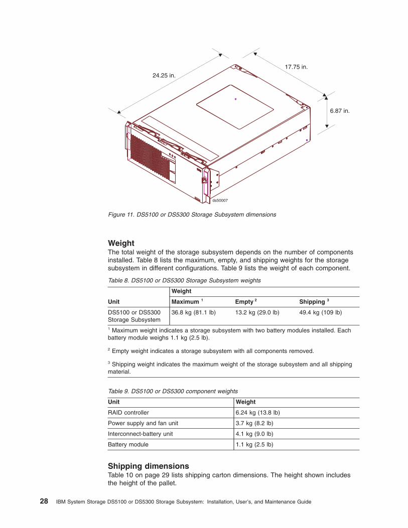
WeightThe total weight of the storage subsystem depends on the number of componentsinstalled. Table 8 lists the maximum, empty, and shipping weights for the storagesubsystem in different configurations. Table 9 lists the weight of each component.
Table 8. DS5100 or DS5300 Storage Subsystem weights
Unit
Weight
Maximum 1 Empty 2 Shipping 3
DS5100 or DS5300Storage Subsystem
36.8 kg (81.1 lb) 13.2 kg (29.0 lb) 49.4 kg (109 lb)
1 Maximum weight indicates a storage subsystem with two battery modules installed. Eachbattery module weighs 1.1 kg (2.5 lb).
2 Empty weight indicates a storage subsystem with all components removed.
3 Shipping weight indicates the maximum weight of the storage subsystem and all shippingmaterial.
Table 9. DS5100 or DS5300 component weights
Unit Weight
RAID controller 6.24 kg (13.8 lb)
Power supply and fan unit 3.7 kg (8.2 lb)
Interconnect-battery unit 4.1 kg (9.0 lb)
Battery module 1.1 kg (2.5 lb)
Shipping dimensionsTable 10 on page 29 lists shipping carton dimensions. The height shown includesthe height of the pallet.
6.87 in.
24.25 in.17.75 in.
ds50007
Figure 11. DS5100 or DS5300 Storage Subsystem dimensions
28 IBM System Storage DS5100 or DS5300 Storage Subsystem: Installation, User’s, and Maintenance Guide

Table 10. DS5100 or DS5300 shipping carton dimensions
Height Width Depth
44.4 cm (17.5 in.) 62.2 cm (24.5 in.) 78.7 cm (31.0 in.)
Environmental requirements and specificationsThis section describes the environmental conditions that are prerequisite toinstalling the unit, and heat and sound conditions that are generated by normaloperation of the unit.
Temperature and humidityTable 11 lists the acceptable temperature and humidity ranges in which the storagesubsystem is designed to operate.
Important: The best practice operating environment air temperature is 22° C (72°F) or lower.
Table 11. Temperature and humidity requirements
Condition Parameter Requirement
Temperature 1 Operating range 10° - 35° C (50° - 95° F)
Maximum rate of change 10° C (18° F) per hour
Storage range 1° - 60° C (33° - 140° F)
Maximum rate of change 15° C (27° F) per hour
Transit range -40° C to 65° C (-40° F to149° F)
Maximum rate of change 20° C (36° F) per hour
Relative humidity (nocondensation)
Operating range 20% to 80%
Storage range 10% to 93%
Transit range 5% to 95%
Maximum dew point 26° C (79° F)
Maximum gradient 10% per hour
Notes:
1. The non-operating environment must not exceed the operating environmentlimits for longer than 60 days.
2. The storage environment must not exceed the operating environment limits forlonger than one year.
3. Substantial deviations from the suggested operating range, in either direction, ifsustained for extended periods of time, will expose the unit to greater risk offailure from external causes.
AltitudeTable 12 lists the acceptable altitudes for operating, storing, and shipping theDS5100 or DS5300.
Table 12. DS5100 or DS5300 altitude ranges
Environment Altitude
Operating 30.5 m (100 ft.) below sea level to 3048 m(10,000 ft.) above sea level
Chapter 1. Introduction 29

Table 12. DS5100 or DS5300 altitude ranges (continued)
Environment Altitude
Storage 30.5 m (100 ft.) below sea level to 3048 m(10,000 ft.) above sea level
Transit 30.5 m (100 ft.) below sea level to 12,000 m(40,000 ft.) above sea level
Airflow and heat dissipationFigure 12 shows the intended airflow for a DS5100 or DS5300. Allow at least 30inches in front of the storage subsystem and at least 24 inches behind the storagesubsystem for service clearance, proper ventilation, and heat dissipation.
Table 13 lists the KVA, watts, and Btu calculations for the DS5100 or DS5300.These values assume the power supplies have a 73 percent efficiency and a powerfactor of 0.99. These tabulated power and heat dissipation values are typical for thestorage subsystem. Maximum configuration units are typically operated at higherdata rates, have larger random access memory (RAM) capacities, or have differenthost interface boards.
Table 13. DS5100 or DS5300 power and heat dissipation
Parameter KVA Watts (ac) Btu per hour
RAID controller90Vrms
.644 636 2175
ds50019
Figure 12. DS5100 or DS5300 airflow
30 IBM System Storage DS5100 or DS5300 Storage Subsystem: Installation, User’s, and Maintenance Guide

Shock and vibration requirementsOperational shock and operational vibration requirements are shown in this section.
Operational Shock: The DS5100 or DS5300 withstands the following shock.Subjecting the equipment to a single shock pulse with the following characteristicswill simulate this level of shock:
v Velocity change = 20 inches per second
v Wave form = Triangular, 10g @3.75 ms
Operational Vibration (Random): While in its normal operating position, theDS5100 or DS5300 continues operating when subjected to a random vibration testusing the criteria shown in Table 14. This test uses a dwell time of 15 minutes atany frequency where vigorous or resonant excitation occurs.
Table 14. DS5100 or DS5300 operational vibration specifications
Parameter Value
Frequency sweep 5 Hz - 150 Hz - 5 Hz
Wave form Sinusoidal, 0.25 g
Acoustic noiseTable 15 lists the maximum sound levels emitted by the storage subsystem.
Table 15. DS5100 or DS5300 sound levels
Measurement Level
Sound power (normal operation) 6.0 bels
Sound pressure (normal operation) 60 dBA
These levels are measured in controlled acoustical environments according to ISO7779 and are reported in accordance with ISO 9296. The declared sound powerlevels indicate an upper limit, below which a large portion of machines operate.Sound pressure levels in your location might exceed the average 1-meter valuesstated because of room reflections and other nearby noise.
Electrical requirementsThis section provides information regarding site power and wiring, storagesubsystem ac power requirements, and power cord routing instructions.
Consider the following information when preparing the DS5100 or DS5300installation site:
v Protective ground – Site wiring must include a protective ground connection tothe ac power source.
Note: Protective ground is also known as safety ground or chassis ground.
v Circuit overloading – Power circuits and associated circuit breakers must providesufficient power and overload protection. To prevent possible damage to the unit,isolate its power source from large switching loads (such as air conditioningmotors, elevator motors, and factory loads).
v Power failures – If a total power failure occurs, the unit automatically performs apower-up recovery sequence without operator intervention after power isrestored.
Chapter 1. Introduction 31

Table 16. IBM System Storage DS5100 or DS5300 ac power requirements
Low Range High Range
Nominal Voltage 110 220
Voltage 90 to 132 VAC 198 to 264 VAC
Frequency (Hertz) 50 to 60 Hz 50 to 60 Hz
Minimum Operating Current 3.49 A1 1.842 A2
Maximum Operating Current 7.055 A1 3.182 A2
Maximum Surge Current 8.4 A1 18.2 A2
1. Typical voltage: 120 V ac, 60 Hz, assumes 75% power-supply efficiency and 0.99 powerfactor
2. Typical voltage: 240 V ac, 60 Hz, assumes 75% power-supply efficiency and 0.99 powerfactor
Site wiring and powerThe storage subsystem uses wide-ranging redundant power supplies thatautomatically accommodate voltages to the ac power source. The power suppliesoperate within the range of 90 VAC to 264 VAC, at a minimum frequency of 50 Hzand a maximum frequency of 60 Hz. The power supplies meet standard voltagerequirements for both domestic (inside USA) and international (outside USA)operation. They use standard industrial wiring with line-to-neutral or line-to-linepower connections.
The agency ratings for the DS5100 or DS5300 is 5 amps at 100 VAC and 2.25amps at 240 VAC. These are the overall maximum currents for this system.
AC power recoveryAfter normal power is restored after a total ac power failure, the DS5100 or DS5300performs power-up recovery procedures automatically without operator intervention.
Power cords and receptaclesThe DS5100 or DS5300 ships with the line jumper cords used to connect theDS5100 or DS5300 to rack power distribution units (PDUs). If you need the acpower cords to connect the DS5100 or DS5300 to wall receptacle outlets, you mustpurchase the appropriate power cords for your country or region as described inAppendix E, “Power cords,” on page 271.
Heat output, airflow, and coolingThe maximum heat output of the storage subsystem is 557 watts (1905 BTU/hr).Each storage subsystem rack-mounted unit requires an airflow of 2.5 m3 (87 ft.3)per minute. The input air temperature to all rack cabinets should be in the range10° C - 35° C (50° F - 95° F). The best practice operating temperature is 22° C (72°F).
When rack cabinets that contain many storage subsystems are to be installedtogether, the following requirements must be met to ensure that the storagesubsystems are adequately cooled:
v Air enters at the front of the rack cabinet and leaves at the back. To prevent theair that is leaving the rack cabinet from entering the intake of another piece ofequipment, you must position the rack cabinets in alternate rows, back-to-backand front-to-front. This arrangement is known as cold aisle/hot aisle and is shownin Figure 13 on page 33.
32 IBM System Storage DS5100 or DS5300 Storage Subsystem: Installation, User’s, and Maintenance Guide

v Where rack cabinets are in rows, each rack cabinet must touch the rack cabinetthat is next to it. This reduces the amount of hot air that can flow around from theback of the rack into the intakes of the storage subsystems that are in that rackcabinet. You should use Suite Attach Kits to completely seal any gaps thatremain between the rack cabinets. For details about Suite Attach Kits, contactyour marketing representative.
v Where rack cabinets are in rows front-to-front or back-to-back, a gap of at least1220 mm (48 in.) must separate the rows across the cold aisle.
v To ensure correct airflow in each rack cabinet, the rack filler plates must beinstalled in unused positions. Also, all the gaps in the front of the rack cabinetsmust be sealed, including the gaps between the storage subsystems.
Cold aisle
Air
cond
ition
er
Hot aisle
back
front
back
back
front
Airflow
front2440 mm betweencenter lines of hotand cold aisle
Perforated tilesor gratings
1220 mm coldaisle width
T42 racks
T42 racks
T42 racks
f10
ug
00
1
Figure 13. Example of cold aisle/hot aisle rack cabinet configuration
Chapter 1. Introduction 33

34 IBM System Storage DS5100 or DS5300 Storage Subsystem: Installation, User’s, and Maintenance Guide

Chapter 2. Installing the storage subsystem
This chapter provides the information that you need to install the storage subsysteminto a rack cabinet.
Before you begin the installation, review the safety information in “Safety” on pageiii.
Chapter 2, “Installing the storage subsystem” provides an overview of the entirestorage subsystem installation process. Read this overview before you begin theinstallation.
Installation overview
Statement 4:
≥ 18 kg (39.7 lb) ≥ 32 kg (70.5 lb) ≥ 55 kg (121.2 lb)
CAUTION:Use safe practices when lifting.
Attention: A fully configured DS5100 or DS5300 weighs 36.8 kg (81.1 lb). At leasttwo other people should help you lift the DS5100 or DS5300 from the shipping box.
The following steps summarize the DS5100 or DS5300 installation process.
1. Review the preparation best practices. See “Preparing for installation” on page37.
2. Prepare the installation site. See “Preparing the site” on page 39.
3. Prepare the rack cabinet. See “Preparing the rack cabinet” on page 39.
4. Fold down and open the sides of the shipping box. Without removing theDS5100 or DS5300 from box, you can remove the DS5100 or DS5300 rackmounting rails and hardware from the box, which is placed on the bottom ofthe shipping box underneath the DS5100 or DS5300 enclosure. Install thesupport rails in the rack cabinet. See “Installing the support rails” on page 40.
5. Record the serial number, machine type and model number, and MACaddresses for the RAID controller management port and iSCSI port (ifinstalled) for your DS5100 or DS5300 in Appendix B, “Records,” on page 257.
The serial number, machine type, and model number are located on top ofeach the DS5100 or DS5300 subsystem unit. The MAC addresses are locatednear the management and iSCSI ports on each RAID controller, as shown in
© Copyright IBM Corp. 2008, 2012 35

Figure 148 on page 258. You may not be able to easily access this informationafter you install the DS5100 or DS5300.
6. Install and secure the DS5100 or DS5300 chassis in the rack cabinet. See“Installing the DS5100 or DS5300 on the support rails” on page 45.
7. Install in the rack cabinet the storage expansion enclosure or enclosures youwill cable to the DS5100 or DS5300. Follow the instructions in the Installation,User's, and Maintenance Guide for your storage expansion enclosure to set upand mount the storage expansion enclosures.
AttentionBefore you power on the DS5100 or DS5300, the storage subsystemmust be cabled to at least one storage expansion enclosure populatedwith the minimum number of drives for the storage expansion enclosure.Otherwise, the DS5100 or DS5300 controllers do not successfullycomplete the power-on process and operate optimally.
All drives in the connected storage expansion enclosure or enclosuresmust contain no prior configuration data. Additionally, if at least two drivesare not installed in each EXP5000 attached storage expansion enclosure,or at least four drives in each EXP5060 storage expansion enclosure, theresulting insufficient load to the storage expansion enclosure powersupplies might cause the drive expansion enclosure power supplies tointermittently appear as failed and then reappear in an optimal state,falsely indicating that the power supplies are bad.
8. Use SFP modules and fibre channel cables to cable the DS5100 or DS5300 tothe storage expansion enclosure or enclosures. See “Connecting storageexpansion enclosures to the DS5100 or DS5300” on page 64.
9. Perform one of the following cabling tasks to enable management of theDS5100 or DS5300 configuration:
v If you are using out-of-band management, cable the DS5100 or DS5300Ethernet ports to either the management workstation or the host. See“Connecting secondary interface cables” on page 135.
v If you are using in-band management, cable the DS5100 or DS5300 hostchannels to the fibre channel host bus adapters (HBAs) in either the hostsor the fibre channel switch that connects to the host HBAs. See either“Connecting hosts directly to the DS5100 or DS5300 Fibre Channel hostports” on page 132, or “Connecting hosts to the DS5100 or DS5300 iSCSIports” on page 134.
10. Connect the power cables for the DS5100 or DS5300. See “Connecting thepower cables” on page 147.
11. Power on the attached storage expansion enclosures and the DS5100 orDS5300 using the procedure described in “Turning on the storage subsystem”on page 155.
12. Install the DS Storage Manager host software on the management workstation(for out-of-band management) or on the host (for in-band management). Forinstructions to install the DS Storage Manager host software, see the IBMSystem Storage DS Storage Manager Version 10 Installation and Host SupportGuidefor the appropriate operating system.
13. Use the DS Storage Manager host software to verify the configuration.
14. Review and perform the procedures described in “Performing the DS4000,DS5100, and DS5300 Health Check process” on page 152.
36 IBM System Storage DS5100 or DS5300 Storage Subsystem: Installation, User’s, and Maintenance Guide
Handling static-sensitive devicesAttention: Static electricity can damage electronic devices and your system. Toavoid damage, keep static-sensitive devices in their static-protective packages untilyou are ready to install them.
To reduce the possibility of electrostatic discharge (ESD), observe the followingprecautions:
v Limit your movement. Movement can cause static electricity to build up aroundyou.
v Handle the device carefully, holding it by its edges or its frame.
v Do not touch solder joints, pins, or exposed printed circuitry.
v Do not leave the device where others can handle and possibly damage thedevice.
v While the device is still in its static-protective package, touch it to an unpaintedmetal part of the system unit for at least two seconds. This drains static electricityfrom the package and from your body.
v Remove the device from its package and install it directly into your system unitwithout setting it down. If it is necessary to set the device down, place it in itsstatic-protective package. Do not place the device on your system unit cover oron a metal table.
v Take additional care when handling devices during cold weather because heatingreduces indoor humidity and increases static electricity.
Preparing for installationBefore installing the DS5100 or DS5300, create a detailed plan of how this unit willbe used in your storage configuration. The plan should include determining RAIDlevels, failover requirements, operating systems to be used, and total storagecapacity requirements.
Complete the following steps to prepare the DS5100 or DS5300 for installation intoa rack cabinet:
1. Prepare the site to meet all area, environmental, power, and site requirements.For more information, see “Specifications” on page 27.
2. Move the shipping box that contains the DS5100 or DS5300 to the site.
Attention: The DS5100 or DS5300 shipping box weighs up to 53.8 kg (118.4lb).
Chapter 2. Installing the storage subsystem 37

Statement 4:
≥ 18 kg (39.7 lb) ≥ 32 kg (70.5 lb) ≥ 55 kg (121.2 lb)
CAUTION:Use safe practices when lifting.
3. Remove the mounting rails, mounting hardware, and line jumper cords from theDS5100 or DS5300 shipping box. Do not remove the DS5100 or DS5300 fromthe shipping box at this time.
Attention: The mounting rails, mounting hardware, and line jumper cords maybe packed beneath the DS5100 or DS5300 in the shipping box. To removethese items from the shipping box without first removing the DS5100 orDS5300, open the two long sides of the shipping box. Then open and fold flatthe two short sides of the shipping box. This enables you to access themounting rails, mounting hardware, and line jumper cords without first removingthe DS5100 or DS5300 from the shipping box.
After you open the DS5100 or DS5300 shipping container and remove themounting rails, mounting hardware, and line jumper cords, check the remainingcontents (see “Inventory checklist” on page 4) without removing the DS5100 orDS5300 from the shipping box. If any items are missing, contact your IBMreseller before proceeding.
4. Assemble the tools and equipment that you will need for installation. Theseinclude the following:
v Region-specific power cords required for the DS5100 or DS5300.
v 5/16 (8 mm) hex nut driver.
v Medium flat-blade screwdriver.
v Anti-static protection (such as a grounding wrist strap).
v Fibre channel and Category 5a or Category 6 Ethernet interface cables andcable straps.
v SFP modules.
v The line cord jumper power cords that are shipped with the DS5100 orDS5300.
v The rack-mounting hardware that ships with the DS5100 or DS5300.
v The appropriate host software kit for your operating system.
The DS5100 or DS5300 ships with your choice of host software kits(Windows, AIX, Linux, Mac OS, SUN Solaris, HP-UX, Linux on POWER, orVMware). The host software kit grants you permission to attach host serversusing the appropriate operating system to the DS5100 or DS5300.
38 IBM System Storage DS5100 or DS5300 Storage Subsystem: Installation, User’s, and Maintenance Guide
The kit includes a DS Storage Manager Support DVD that has theappropriate IBM DS Storage Manager host software. If you order more thanone host software kit, the additional kits may also be shipped in the DS5100or DS5300 shipping box.
The DVD also includes the DS Storage Subsystem controller firmware.Controller firmware can be downloaded from the IBM support Web site forDS5100 or DS5300 storage products:
www.ibm.com/systems/support/storage/disk
Note: Depending on your DS5100 or DS5300 model, you may need topurchase the appropriate host software kit for your host serveroperating system. Contact your IBM representative or reseller for moreinformation.
5. Continue with “Preparing the site.”
Preparing the siteThis section lists the floor space requirements and weight information for thestorage subsystem. For information on interface cables and connections, seeChapter 3, “Cabling the storage subsystem,” on page 49.
Floor space: The floor area at the installation site must provide the followingconditions:
v Sufficient space to install the storage subsystem
v Enough stability to support the weight of the fully configured storage subsystemand associated systems.
Ensure that all requirements, such as floor space, air conditioning, and electricalservice, have been met. Other site preparation activities include the following tasks:
v To ensure that there is enough room to move around the cabinet and installmodules, clear space at the installation area.
v Install uninterruptible power supply (UPS) devices.
v If applicable, install host servers with fibre channel host bus adapters (HBAs),fibre channel switches, or other devices.
v Route interface cables from the fibre channel HBA ports in the hosts or fibrechannel switches to the installation area.
v Route main power cords to the installation area.
Continue with “Preparing the rack cabinet.”
Preparing the rack cabinetImportant: Before you install the storage subsystem in a rack cabinet, keep in mindthe following considerations:
v Review the documentation that comes with your rack enclosure for safety andcabling considerations.
v If you are using a non-IBM rack or cabinet, review the information in Appendix D,“Specifications for non-IBM rack installation,” on page 263.
v Do not extend more than one device out of the rack cabinet at the same time.
v Install the storage subsystem in a 22° C (72° F) environment. See“Environmental requirements and specifications” on page 29 for details.
v To ensure proper airflow, do not block the air vents; ensure at least 15 cm (6 in.)of air space.
Chapter 2. Installing the storage subsystem 39

v To ensure rack stability, load the rack starting at the bottom.
v If you install multiple components in the rack, do not overload the power outlets.
v Always connect the storage subsystem to a properly grounded outlet.
v Always connect the IBM-certified rack power distribution units (PDUs) to at leasttwo independent power circuits or sources.
v If you are installing EXP5060 expansion enclosures and storage subsystems,install the EXP5060 expansion enclosures first, starting at the bottom of the rack.
Complete the following steps to prepare the rack cabinet before you install thestorage subsystem:
1. Move, unpack, and level the rack at the installation site (if needed).
2. Remove the external rack panels.
3. If necessary, stop all I/O activity to the devices in the rack.
4. If necessary, turn off all drive enclosure and rack power. Disconnect existingpower, network, and other external cables.
5. Install any additional interface cables and power cables.
After you have completed these steps, continue with “Installing the support rails.”
Installing the support rails
Attention: Duplicate copies of the rack mounting templates are provided inAppendix C, “Rack mounting templates,” on page 259. If you want to tear out thetemplates from this document for easier use, use the copies provided inAppendix C, “Rack mounting templates,” on page 259 instead of the copies in thissection.
Use the following templates and instructions to identify the proper locations forinserting M5 screws when mounting the support rails and DS5100 or DS5300 to arack cabinet. The locations for the M5 screws are highlighted in the templates.
Hold the appropriate template up to each side of the rack cabinet at the 4–Usection where you will install the DS5100 or DS5300. The highlighted squares oneach side of the template mark the positions where you will thread the M5 screwsthat secure the rails and the DS5100 or DS5300 to the front and rear of the cabinet.
The DS5100 or DS5300 is 4 U high. Align the template with the rack at a Uboundary. U boundaries are shown as horizontal dashed lines in the rack mountingtemplates.
Note: The mounting holes shown in the following rack mounting templates aresquare. The holes in your rack might be round, square, or threaded. Use thewashers supplied under the heads of the M5 screws when mounting to rackswith square holes.
40 IBM System Storage DS5100 or DS5300 Storage Subsystem: Installation, User’s, and Maintenance Guide

FRONTRack Mounting
Template
0 U
2 U
3 U
1 U
4 U
Rail assembly(Front left)
Rail assembly(Front right)
Rail assembly(Front left)
Rail assembly(Front right)
4 U
3 U
2 U
1 U
0 UFront
Figure 14. DS5100 or DS5300 front rack mounting template
Chapter 2. Installing the storage subsystem 41

Before installing the DS5100 or DS5300 in a rack cabinet, you must install the railsand rack-mounting hardware that come with your storage subsystem. The DS5100or DS5300 requires an Electronic Industries Association (EIA) 310-D Type A 19-inchrack cabinet.
The distance between EIA rails, from the front to the rear of the rack cabinet, is60.96 cm (24 in.) minimum and 81.28 cm (32 in.) maximum. This rack cabinetconforms to the EIA standard. Where you place the support rails in the rack cabinetdepends on where you intend to position the storage subsystem.
Note: If you are using a non-IBM rack or cabinet, review the information inAppendix D, “Specifications for non-IBM rack installation,” on page 263.
REARRack Mounting
Template
Rail assembly(Rear left)
Rail assembly(Rear right)
4 U
3 U
2 U
1 U
0 U0 U
2 U
3 U
1 U
4 U
Printed in the U.S.A
Figure 15. DS5100 or DS5300 rear rack mounting template
42 IBM System Storage DS5100 or DS5300 Storage Subsystem: Installation, User’s, and Maintenance Guide
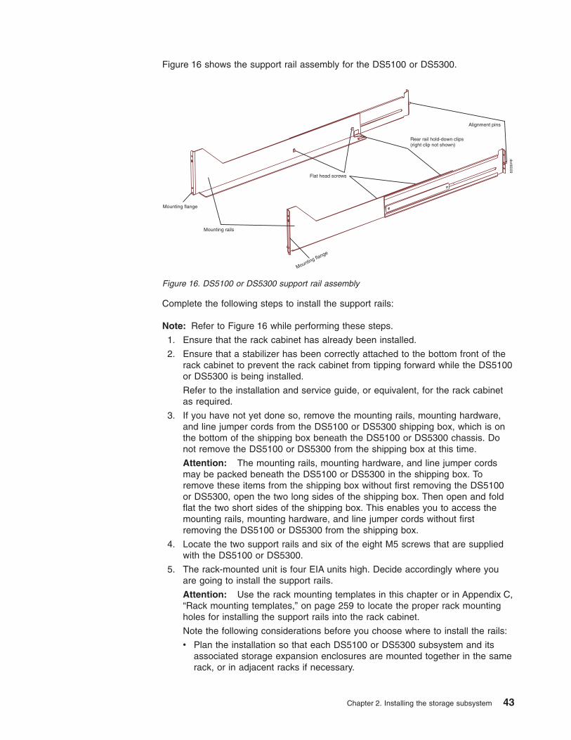
Figure 16 shows the support rail assembly for the DS5100 or DS5300.
Complete the following steps to install the support rails:
Note: Refer to Figure 16 while performing these steps.
1. Ensure that the rack cabinet has already been installed.
2. Ensure that a stabilizer has been correctly attached to the bottom front of therack cabinet to prevent the rack cabinet from tipping forward while the DS5100or DS5300 is being installed.
Refer to the installation and service guide, or equivalent, for the rack cabinetas required.
3. If you have not yet done so, remove the mounting rails, mounting hardware,and line jumper cords from the DS5100 or DS5300 shipping box, which is onthe bottom of the shipping box beneath the DS5100 or DS5300 chassis. Donot remove the DS5100 or DS5300 from the shipping box at this time.
Attention: The mounting rails, mounting hardware, and line jumper cordsmay be packed beneath the DS5100 or DS5300 in the shipping box. Toremove these items from the shipping box without first removing the DS5100or DS5300, open the two long sides of the shipping box. Then open and foldflat the two short sides of the shipping box. This enables you to access themounting rails, mounting hardware, and line jumper cords without firstremoving the DS5100 or DS5300 from the shipping box.
4. Locate the two support rails and six of the eight M5 screws that are suppliedwith the DS5100 or DS5300.
5. The rack-mounted unit is four EIA units high. Decide accordingly where youare going to install the support rails.
Attention: Use the rack mounting templates in this chapter or in Appendix C,“Rack mounting templates,” on page 259 to locate the proper rack mountingholes for installing the support rails into the rack cabinet.
Note the following considerations before you choose where to install the rails:
v Plan the installation so that each DS5100 or DS5300 subsystem and itsassociated storage expansion enclosures are mounted together in the samerack, or in adjacent racks if necessary.
Rear rail hold-down clips(right clip not shown)
Flat head screws
Mounting rails
Alignment pins
ds48009
Mounting flange
Mounting flange
Figure 16. DS5100 or DS5300 support rail assembly
Chapter 2. Installing the storage subsystem 43

v When you install the DS5100 or DS5300 and associated storage expansionenclosures into a rack cabinet, install each device in the lowest availableposition and work upwards so that the rack does not become unstable.
Note: If you are installing more than one DS5100 or DS5300, install eachDS5100 or DS5300 and its associated storage expansion enclosuresin a separate rack cabinet.
v If appropriate, allow for possible later installation of other units.
v If necessary, remove the rack power distribution units (PDUs) before youinstall the support rails.
v For procedures and more information, refer to the installation and serviceguide, or equivalent, for the rack cabinet.
6. Starting with the left rail, use a medium flat-blade screwdriver to loosen the twoflat-head rail adjustment screws. See Figure 16 on page 43.
7. Hold the front of the left rail against the inside of the front rack-mountingflange, and then extend the rear of the support rail until it makes contact withthe rear rack mounting flange. The alignment pins at the rear of the rail shouldslide into the holes at the rear of the rack.
8. From the front of the rack, with the rail mounting flanges inside of the frontrack-mounting flange, use the 5/16 (8 mm) hex nut driver to thread and looselytighten the lower M5 screw only. Use the front rack mounting template or usethe copy in Appendix C, “Rack mounting templates,” on page 259) to locate theproper rack mounting hole for installing this screw.
Attention: Do not completely tighten the screw until you have installed theDS5100 or DS5300 in the rack cabinet.
9. From the rear of the rack, thread and loosely tighten two M5 screws using the5/16 (8 mm) hex nut driver. Use the rear rack mounting template or use thecopy in Appendix C, “Rack mounting templates,” on page 259) to locate theproper rack mounting holes for installing these screws. Do not completelytighten the screws until you have installed the DS5100 or DS5300 in the rackcabinet.
When you are finished installing the left rail, the rail should be attached to thecabinet using one M5 screw in the front and two M5 screws at the back. Allthree M5 screws should be loosely tightened.
10. Repeat step 6 through step 9 for the right rail.
11. Tighten the rail adjustment screws on both rails.
12. Continue with “Installing the DS5100 or DS5300.”
Installing the DS5100 or DS5300The DS5100 or DS5300 contains two controllers, two power supply and fan units,and one interconnect-battery unit. The RAID controllers are located at the back ofthe unit. The two power supply and fan units and the interconnect-battery unit arelocated behind the front bezel.
Figure 17 on page 45 shows the front bezel of the DS5100 or DS5300, a front viewwithout the cover, and a back view. Figure 17 on page 45 also shows the locationsof the components that are referenced during this installation procedure.
44 IBM System Storage DS5100 or DS5300 Storage Subsystem: Installation, User’s, and Maintenance Guide
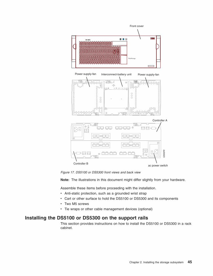
Note: The illustrations in this document might differ slightly from your hardware.
Assemble these items before proceeding with the installation.
v Anti-static protection, such as a grounded wrist strap
v Cart or other surface to hold the DS5100 or DS5300 and its components
v Two M5 screws
v Tie wraps or other cable management devices (optional)
Installing the DS5100 or DS5300 on the support railsThis section provides instructions on how to install the DS5100 or DS5300 in a rackcabinet.
ac power switchController B
Power supply-fanInterconnect-battery unit
Front cover
Power supply-fan
ds50023
Controller A
Figure 17. DS5100 or DS5300 front views and back view
Chapter 2. Installing the storage subsystem 45
Attention: If you have not yet done so, record the serial number, machine typeand model number, and MAC addresses for your DS5100 or DS5300 inAppendix B, “Records,” on page 257. The serial number, machine type, and modelnumber are located on top of each storage subsystem. The MAC addresses arelocated near the Ethernet ports on each RAID controller, as shown in Figure 148 onpage 258.
Use the following procedure to install the DS5100 or DS5300 on support rails in arack cabinet. To mount a storage subsystem in the rack cabinet, all support railsmust be installed in their correct locations. If you need to install the rails, see“Installing the support rails” on page 40.
CAUTION:Never install components or other equipment in the top half of a rackmountcabinet while the bottom half is empty. Doing so can cause the cabinet tobecome top-heavy and to tip over. Always install hardware in the lowestavailable position in the cabinet.
Before installing the storage subsystem in the cabinet, ensure that there are noobstructions, either in the cabinet or outside the cabinet, that would make readyremoval and replacement of any of the components impossible. Check forobstructions at the front and rear of the cabinet.
Operational ShockThe DS5100 or DS5300 withstands a free-fall drop from 0.5 inches onto ahard surface. Subjecting the equipment to a single shock pulse with thefollowing characteristics will simulate this level of shock:
Velocity change = 20 inches per second ; Wave form = Triangular,[email protected] ms
Operational Vibration (Sweep)While in its normal operating position, the DS5100 or DS5300 continuesoperating when subjected to the following vibration sweep. The test willinclude a dwell time of 15 minutes at any frequency where vigorous orresonant excitation occurs.
v Frequency sweep = 5 Hz – 150 Hz – 5 Hz
v Wave form = Sinusoidal, 0.25g
Note: You should have at least two other people available to help you lift the unitfrom the shipping box and into the rack cabinet
1. Remove the empty DS5100 or DS5300 from the shipping box and set thestorage subsystem in the cabinet. Figure 18 on page 47 shows the correctorientation of the empty storage subsystem to the cabinet and support rail.
The following steps will help you safely install the DS5100 or DS5300 on thesupport rails:
a. If you have installed a screw in the upper mounting hole at the front of eachsupport rail, remove the upper screws. These two screws are used later tosecure the front of the storage subsystem to the rack.
b. Move the empty storage subsystem from the shipping box and to the front ofthe cabinet.
c. With help from another person, place the back of the storage subsystem onthe support rails, and then slide the storage subsystem into the cabinet.
46 IBM System Storage DS5100 or DS5300 Storage Subsystem: Installation, User’s, and Maintenance Guide

Attention: When you slide the storage subsystem into the cabinet, verifythat the back of the DS5100 or DS5300 is secured by the hold-down clipslocated at the back of each rail. With the M5 rail screws loosely threaded,you can make minor adjustments to the rails to ensure that the subsystemlatches in the hold-down clips. The hold-down clips are shown in Figure 16on page 43.
2. Secure the storage subsystem to the cabinet. Figure 18 shows how to securethe DS5100 or DS5300 to the vertical members of the cabinet.
The following steps will help you safely secure the DS5100 or DS5300 in therack cabinet:
a. Align the front mounting holes on the storage subsystem flanges with themounting holes on the cabinet.
b. Using the 5/16 (8 mm) hex nut driver, insert one M5 screw into the hole oneach flange, and tighten the screws completely to secure the front of thestorage subsystem to the cabinet.
3. At the front and the rear of the rack cabinet, use the 5/16 (8 mm) hex nut driverto finish tightening the other three M5 screws for each rail.
4. Continue with Chapter 3, “Cabling the storage subsystem,” on page 49.
ScrewMounting hole Support rail
ds50029
Figure 18. Securing the DS5100 or DS5300 to the rack cabinet
Chapter 2. Installing the storage subsystem 47

48 IBM System Storage DS5100 or DS5300 Storage Subsystem: Installation, User’s, and Maintenance Guide

Chapter 3. Cabling the storage subsystem
After the storage subsystem is installed in its permanent location, you must cable itto hosts, drives, and other external devices, depending on your hardwareconfiguration. This chapter provides fibre channel and power cabling information forthe storage subsystem. It also provides information about configuring the storagesubsystem.
This chapter addresses the following cabling and configuration topics:
v “Working with SFPs, SFP+s, and fiber-optic cables”
v “Connecting storage expansion enclosures to the DS5100 or DS5300” on page64
v “Connecting hosts directly to the DS5100 or DS5300 Fibre Channel host ports”on page 132
v “Connecting secondary interface cables” on page 135
v “Configuring the storage subsystem” on page 136
v “Installing the storage subsystem configuration” on page 147
v “Connecting the power cables” on page 147
Working with SFPs, SFP+s, and fiber-optic cablesEach RAID controller has Fibre Channel drive channel connections. Depending onthe type of host interface card installed, it also has Fibre Channel host connections.You use a small-form factor pluggable transceiver (SFP) to connect each hostchannel port and drive channel port to hosts and storage expansion enclosures.
In addition, a 10 Gbps host interface card has optical host connections. Use a 10Gbps small-form factor pluggable transceiver (SFP+) to connect each port of a 10Gbps host interface card to a 10 Gbps Ethernet switch.
The SFP or SFP+ is inserted into the port, and then a fiber-optic cable is insertedinto the SFP or SFP+. The other end of the fiber-optic cable connects to an externaldevice. SFPs and SFP+s are laser products.
Note: For 10 Gbps connections, use 50/125 um OM3 fiber cables.
© Copyright IBM Corp. 2008, 2012 49
Statement 3:
CAUTION:When laser products (such as CD-ROMs, DVD drives, fiber optic devices, ortransmitters) are installed, note the following:
v Do not remove the covers. Removing the covers of the laser product couldresult in exposure to hazardous laser radiation. There are no serviceableparts inside the device.
v Use of controls or adjustments or performance of procedures other thanthose specified herein might result in hazardous radiation exposure.
DANGER
Some laser products contain an embedded Class 3A or Class 3B laserdiode. Note the following.
Laser radiation when open. Do not stare into the beam, do not view directlywith optical instruments, and avoid direct exposure to the beam.
Handling fibre-optic cables
Note: IBM Fibre Channel (FC) cable options have been tested and approved forthe IBM DS storage products. For optimal performance and compatibility,always use IBM FC cable options when installing the IBM DS products.
Attention: To avoid damage to your fibre-optic cables, follow these guidelines:
v For devices on slide rails, leave enough slack in the cables so they do not bendto a diameter of less than 76 mm (3 in.), or a radius less than 38 mm (1.5 in.),when extended or become pinched when retracted.
v Do not overtighten the cable straps or bend the cables to a diameter of less than76 mm (3 in.), or a radius less than 38 mm (1.5 in.).
v When storing excess or unused fibre-optic cables, do not bend the cables to adiameter of less than 76 mm (3 in.), or a radius less than 38 mm (1.5 in.) or wrapthem around themselves. See Figure 19 on page 51.
v Loop diameter of 76 mm (3 in.) and bend radius of 38 mm (1.5 in.) for fibre-opticcables are best practices minimums. Loops or bends smaller than this maycause damage to your fibre-optic cables. It is best practice to use loop diametersand bend radii that are greater than these minimums.
v Do not route the cable along a folding cable-management arm.
v Route the cable away from places where it can be damaged by other devices inthe rack cabinet.
v Do not put excess weight on the cable at the connection point. Be sure that thecable is well supported.
v Do not use plastic cable ties in place of the provided cable straps.
v The following are the supported maximum cable lengths:
50 IBM System Storage DS5100 or DS5300 Storage Subsystem: Installation, User’s, and Maintenance Guide

– 1 Gbps: 500 meters 50/125 um OM2 fiber, 300 meters 62.5/125 um OM1 fiber
– 2 Gbps: 300 meters 50/125 um OM2 fiber, 150 meters 62.5/125 um OM1 fiber
– 4 Gbps: 150 meters 50/125 um OM2 fiber, 70 meters 62.5/125 um OM1 fiber
– 8 Gbps: 150 meters (492 ft) of 50/125 um OM3 fiber, 50 meters (164 ft.) of50/125 um OM2 fiber, 21 meters (68 ft.) of 62.5/125 um OM1 fiber.
– 10 Gbps: 300m (984ft) of 50/125 um OM3 fiber
Installing SFP or SFP+ modulesThe DS5100 or DS5300 Fibre Channel host and drive channel ports require SFPmodules. The DS5100 or DS5300 10 Gbps iSCSI host port requires SFP+ modules.SFP and SFP+ modules are used to convert electrical signals to optical signals thatare required for fibre channel (SFP) or optical iSCSI (SFP+) transmission to andfrom RAID controllers. The DS5100 or DS5300 supports two types of SFP modules:one with a plastic latch and one with a wire latch. The SFP+ modules only comewith a wire latch. After you install the SFP or SFP+ modules, use fiber-optic cablesto connect the DS5100 or DS5300 to other optical devices.
Notes:
1. The 1 Gbps iSCSI host port comes with an on-board RJ-45 interface module.No additional hardware is required.
2. IBM SFP and SFP+ options have been tested and approved for the IBM DSstorage products. For optimal performance and compatibility, always use IBMSFP and SFP+ options when installing the IBM DS products.
Before you install SFP or SFP+ modules and fiber-optic cables, read the followinginformation:
v Use only short-wave/multimode SFPs in DS5100 or DS5300 host or drive ports.In DS5100 or DS5300 configurations, you may use long-wave SFPs only in fibrechannel switches that connect DS5100 or DS5300s over long distances.
1.5 inch(38 mm)radius
3.0 inch(76 mm)diameter
ds47
0104
Figure 19. Best practice bending and looping specifications for fibre-optic cables
Chapter 3. Cabling the storage subsystem 51

v The SFP or SFP+ module housing has an integral guide key designed to preventyou from inserting the SFP or SFP+ module improperly.
v Use minimal pressure when you insert the SFP or SFP+ module into a port.Forcing the SFP or SFP+ module into a port could cause damage to the SFP orSFP+ module or the port.
v You can insert or remove the SFP or SFP+ module while the port is powered on.
v Do not install an SFP in any port that will not have a fibre optic cable attached.Additionally, it is a best practice that you remove any SFP from any port thatdoes not have fibre optic cables attached.
v The operational loop performance is not affected when you install or remove anSFP module.
v You must insert the SFP or SFP+ module into a port before you connect thefiber-optic cable.
v You must remove the fiber-optic cable from the SFP or SFP+ module before youremove the SFP or SFP+ module from the fibre channel port. See “RemovingSFP or SFP+ modules” on page 54 for more information.
v The speed of the SFP or SFP+ module determines the maximum operatingspeed of the fibre channel port in which the SFP or SFP+ is installed.
v The SFP part number (printed on the manufacturing label attached to the SFP)identifies the speed at which the SFP module operates. Verify that you use SFPswith the correct speed requirements in your environment.
Note: You can also use the management software for the DS5100 or DS5300 orthe fibre channel switches to display the properties of the SFPs used inyour configurations.
v The SFP or SFP+ FRU part number is printed on the manufacturing labelattached to the SFP or SFP+. Use this FRU PN information if you order areplacement of a failed SFP or SFP+ module.
To install an SFP or SFP+ module, complete the following steps.
52 IBM System Storage DS5100 or DS5300 Storage Subsystem: Installation, User’s, and Maintenance Guide
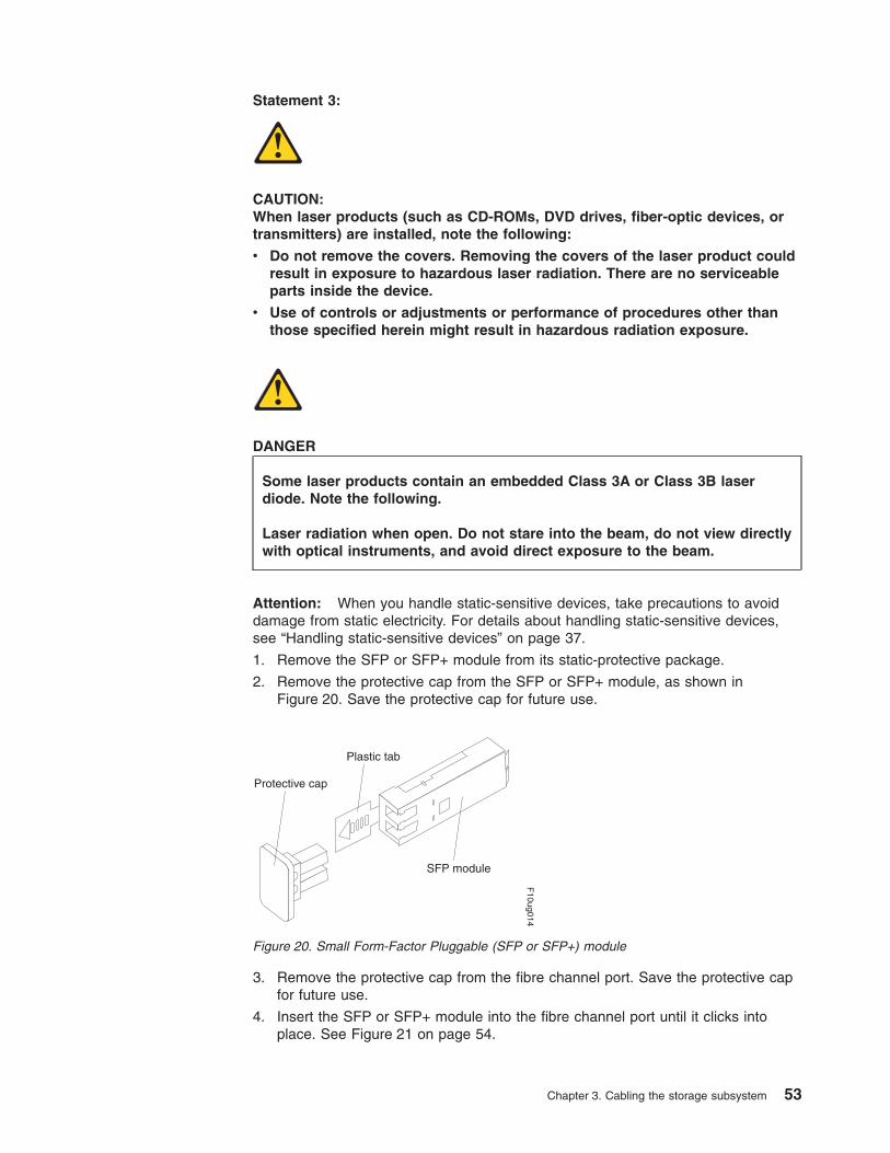
Statement 3:
CAUTION:When laser products (such as CD-ROMs, DVD drives, fiber-optic devices, ortransmitters) are installed, note the following:
v Do not remove the covers. Removing the covers of the laser product couldresult in exposure to hazardous laser radiation. There are no serviceableparts inside the device.
v Use of controls or adjustments or performance of procedures other thanthose specified herein might result in hazardous radiation exposure.
DANGER
Some laser products contain an embedded Class 3A or Class 3B laserdiode. Note the following.
Laser radiation when open. Do not stare into the beam, do not view directlywith optical instruments, and avoid direct exposure to the beam.
Attention: When you handle static-sensitive devices, take precautions to avoiddamage from static electricity. For details about handling static-sensitive devices,see “Handling static-sensitive devices” on page 37.
1. Remove the SFP or SFP+ module from its static-protective package.
2. Remove the protective cap from the SFP or SFP+ module, as shown inFigure 20. Save the protective cap for future use.
3. Remove the protective cap from the fibre channel port. Save the protective capfor future use.
4. Insert the SFP or SFP+ module into the fibre channel port until it clicks intoplace. See Figure 21 on page 54.
Protective cap
SFP module
Plastic tab
F10ug014
Figure 20. Small Form-Factor Pluggable (SFP or SFP+) module
Chapter 3. Cabling the storage subsystem 53
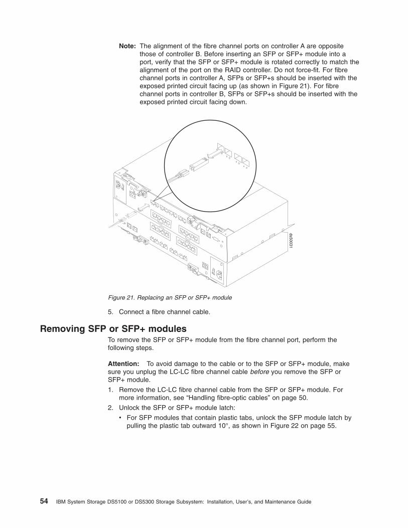
Note: The alignment of the fibre channel ports on controller A are oppositethose of controller B. Before inserting an SFP or SFP+ module into aport, verify that the SFP or SFP+ module is rotated correctly to match thealignment of the port on the RAID controller. Do not force-fit. For fibrechannel ports in controller A, SFPs or SFP+s should be inserted with theexposed printed circuit facing up (as shown in Figure 21). For fibrechannel ports in controller B, SFPs or SFP+s should be inserted with theexposed printed circuit facing down.
5. Connect a fibre channel cable.
Removing SFP or SFP+ modulesTo remove the SFP or SFP+ module from the fibre channel port, perform thefollowing steps.
Attention: To avoid damage to the cable or to the SFP or SFP+ module, makesure you unplug the LC-LC fibre channel cable before you remove the SFP orSFP+ module.
1. Remove the LC-LC fibre channel cable from the SFP or SFP+ module. Formore information, see “Handling fibre-optic cables” on page 50.
2. Unlock the SFP or SFP+ module latch:
v For SFP modules that contain plastic tabs, unlock the SFP module latch bypulling the plastic tab outward 10°, as shown in Figure 22 on page 55.
ds50031
Figure 21. Replacing an SFP or SFP+ module
54 IBM System Storage DS5100 or DS5300 Storage Subsystem: Installation, User’s, and Maintenance Guide

v For SFP or SFP+ modules that contain wire tabs, unlock the SFP or SFP+module latch by pulling the wire latch outward 90°, as shown in Figure 23.
3. With the SFP or SFP+ latch in the unlocked position, extract the SFP or SFP+module.
v For SFP modules that contain plastic tabs, slide the SFP module out of theport.
v For SFP or SFP+ modules that contain wire tabs, grasp the wire latch andpull the SFP or SFP+ module out of the port.
4. Replace the protective cap on the SFP or SFP+ module.
5. Place the SFP or SFP+ module into a static-protective package.
6. Replace the protective cap on the port.
Installing fiber-optic cablesTo connect the fiber-optic cables, perform the following steps:
1. Remove the protective cap from the fiber-optic cable. See Figure 24 on page56.
Protective cap
SFP module
10o
Plastic tab
F10ug009
Figure 22. Unlocking the SFP module latch - plastic variety
Protective cap
SFP module90o
Wire tab
F10ug010
Figure 23. Unlocking the SFP or SFP+ module latch - wire variety
Chapter 3. Cabling the storage subsystem 55

2. Connect the fiber-optic cable to the installed SFP or SFP+, as shown inFigure 25.
3. Check the LEDs on the RAID controller. When the RAID controller is operatingproperly, the amber Needs Attention LED is off. For information about the statusof the RAID controller LEDs, see “RAID controller LEDs” on page 169.
4. To remove the fiber-optic cables, gently pull the fiber-optic cable from the SFPor SFP+; then replace the protective caps.
Using LC-LC fibre-channel cablesThe LC-LC fibre-channel cable is a fiber-optic cable that you use to connectDS5100 or DS5300 fibre channel ports to one of the following devices:
v An SFP module installed in a fibre channel switch port
v An SFP module of the host bus adapter port
Protective cap
Fiber-opticcable
F10ug011
Figure 24. Removing caps from fiber-optic cables
ds50031
Figure 25. Connecting fiber-optic cable to SFP or SFP+
56 IBM System Storage DS5100 or DS5300 Storage Subsystem: Installation, User’s, and Maintenance Guide
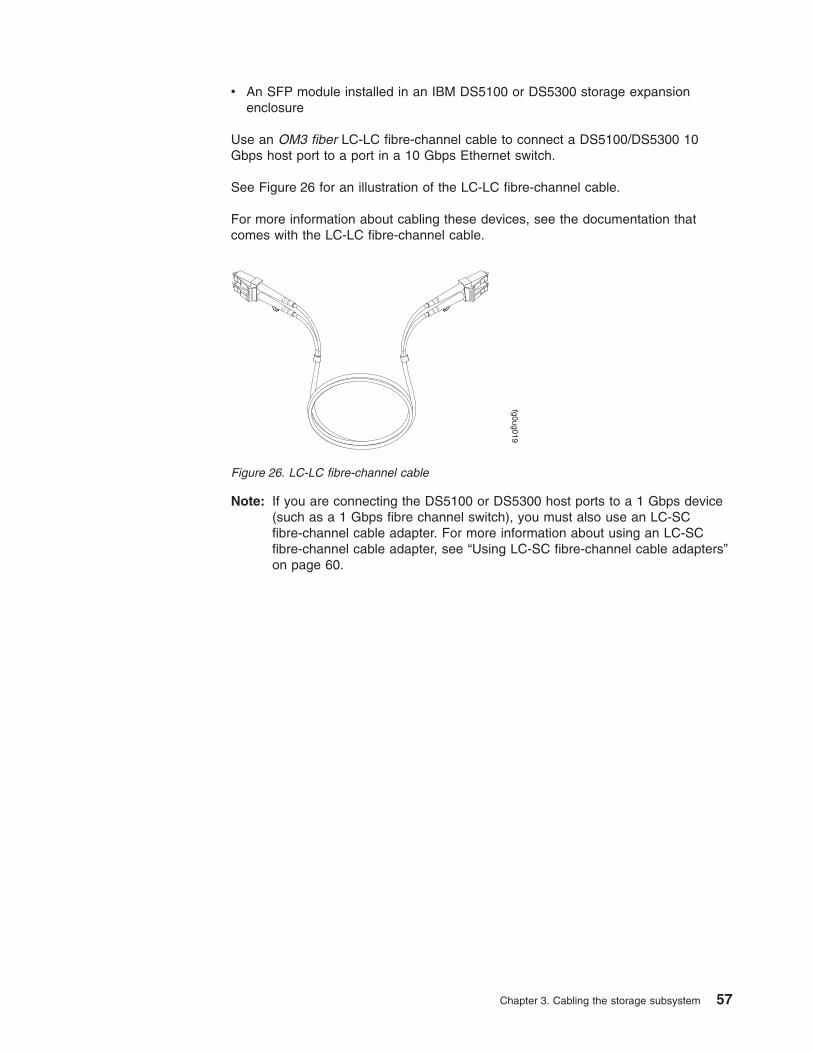
v An SFP module installed in an IBM DS5100 or DS5300 storage expansionenclosure
Use an OM3 fiber LC-LC fibre-channel cable to connect a DS5100/DS5300 10Gbps host port to a port in a 10 Gbps Ethernet switch.
See Figure 26 for an illustration of the LC-LC fibre-channel cable.
For more information about cabling these devices, see the documentation thatcomes with the LC-LC fibre-channel cable.
Note: If you are connecting the DS5100 or DS5300 host ports to a 1 Gbps device(such as a 1 Gbps fibre channel switch), you must also use an LC-SCfibre-channel cable adapter. For more information about using an LC-SCfibre-channel cable adapter, see “Using LC-SC fibre-channel cable adapters”on page 60.
fg0ug019
Figure 26. LC-LC fibre-channel cable
Chapter 3. Cabling the storage subsystem 57
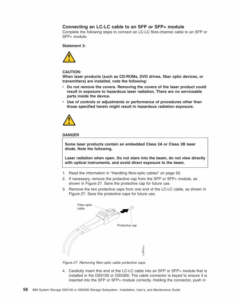
Connecting an LC-LC cable to an SFP or SFP+ moduleComplete the following steps to connect an LC-LC fibre-channel cable to an SFP orSFP+ module:
Statement 3:
CAUTION:When laser products (such as CD-ROMs, DVD drives, fiber optic devices, ortransmitters) are installed, note the following:
v Do not remove the covers. Removing the covers of the laser product couldresult in exposure to hazardous laser radiation. There are no serviceableparts inside the device.
v Use of controls or adjustments or performance of procedures other thanthose specified herein might result in hazardous radiation exposure.
DANGER
Some laser products contain an embedded Class 3A or Class 3B laserdiode. Note the following.
Laser radiation when open. Do not stare into the beam, do not view directlywith optical instruments, and avoid direct exposure to the beam.
1. Read the information in “Handling fibre-optic cables” on page 50.
2. If necessary, remove the protective cap from the SFP or SFP+ module, asshown in Figure 27. Save the protective cap for future use.
3. Remove the two protective caps from one end of the LC-LC cable, as shown inFigure 27. Save the protective caps for future use.
4. Carefully insert this end of the LC-LC cable into an SFP or SFP+ module that isinstalled in the DS5100 or DS5300. The cable connector is keyed to ensure it isinserted into the SFP or SFP+ module correctly. Holding the connector, push in
Protective cap
Fiber-opticcable
F10ug011
Figure 27. Removing fiber-optic cable protective caps
58 IBM System Storage DS5100 or DS5300 Storage Subsystem: Installation, User’s, and Maintenance Guide

the cable until it clicks into place, as shown in Figure 28.
5. Remove the two protective caps from the other end of the LC-LC cable. Savethe protective caps for future use.
6. Connect this end of the LC-LC cable to the SFP or SFP+ module that isinstalled in one of the following devices.
v DS5100 or DS5300 storage expansion enclosure
v Fibre channel switch
v Host bus adapter
Removing an LC-LC fibre-channel cable
Attention: To avoid damaging the LC-LC cable or SFP or SFP+ module, makesure that you observe the following precautions.
v Press and hold the lever to release the latches before you remove the cable fromthe SFP or SFP+ module.
v Ensure that the levers are in the released position when you remove the cable.
v Do not grasp the SFP or SFP+ module plastic tab when you remove the cable.
Complete the following steps to remove an LC-LC fibre-channel cable:
1. On the end of the LC-LC cable that connects into the SFP or SFP+ module orhost bus adapter, press down and hold the lever to release the latches, asshown in Figure 29.
F10ug016
Figure 28. Inserting an LC-LC fibre-channel cable into an SFP or SFP+ module
Lever
Latches f10ug018
Figure 29. LC-LC fibre-channel cable lever and latches
Chapter 3. Cabling the storage subsystem 59
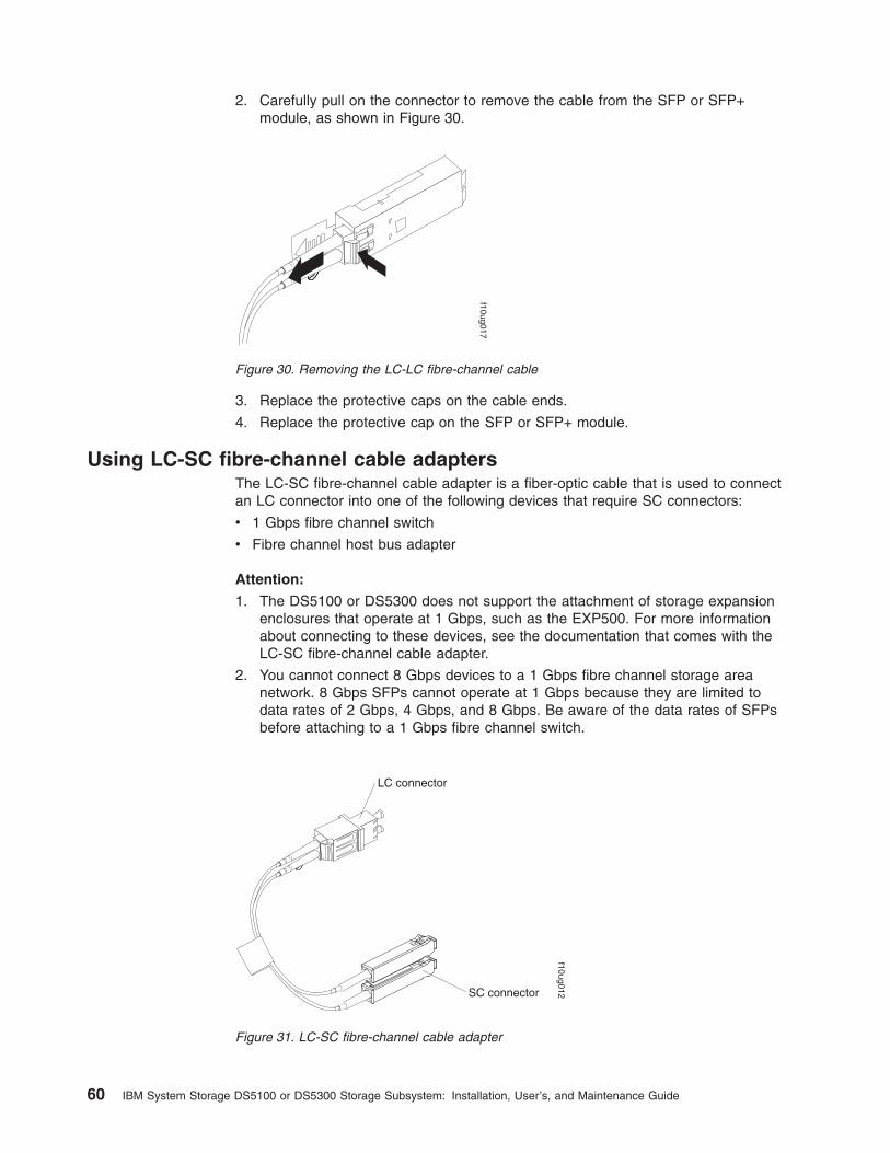
2. Carefully pull on the connector to remove the cable from the SFP or SFP+module, as shown in Figure 30.
3. Replace the protective caps on the cable ends.
4. Replace the protective cap on the SFP or SFP+ module.
Using LC-SC fibre-channel cable adaptersThe LC-SC fibre-channel cable adapter is a fiber-optic cable that is used to connectan LC connector into one of the following devices that require SC connectors:
v 1 Gbps fibre channel switch
v Fibre channel host bus adapter
Attention:
1. The DS5100 or DS5300 does not support the attachment of storage expansionenclosures that operate at 1 Gbps, such as the EXP500. For more informationabout connecting to these devices, see the documentation that comes with theLC-SC fibre-channel cable adapter.
2. You cannot connect 8 Gbps devices to a 1 Gbps fibre channel storage areanetwork. 8 Gbps SFPs cannot operate at 1 Gbps because they are limited todata rates of 2 Gbps, 4 Gbps, and 8 Gbps. Be aware of the data rates of SFPsbefore attaching to a 1 Gbps fibre channel switch.
f10ug017
Figure 30. Removing the LC-LC fibre-channel cable
LC connector
SC connector
f10ug012
Figure 31. LC-SC fibre-channel cable adapter
60 IBM System Storage DS5100 or DS5300 Storage Subsystem: Installation, User’s, and Maintenance Guide

The following sections provide the procedures for properly connecting and removingan LC-SC fibre-channel cable.
Chapter 3. Cabling the storage subsystem 61
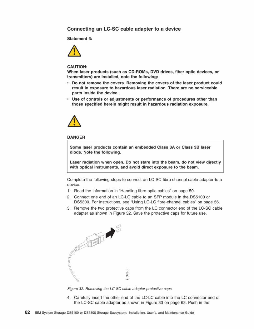
Connecting an LC-SC cable adapter to a device
Statement 3:
CAUTION:When laser products (such as CD-ROMs, DVD drives, fiber optic devices, ortransmitters) are installed, note the following:
v Do not remove the covers. Removing the covers of the laser product couldresult in exposure to hazardous laser radiation. There are no serviceableparts inside the device.
v Use of controls or adjustments or performance of procedures other thanthose specified herein might result in hazardous radiation exposure.
DANGER
Some laser products contain an embedded Class 3A or Class 3B laserdiode. Note the following.
Laser radiation when open. Do not stare into the beam, do not view directlywith optical instruments, and avoid direct exposure to the beam.
Complete the following steps to connect an LC-SC fibre-channel cable adapter to adevice:
1. Read the information in “Handling fibre-optic cables” on page 50.
2. Connect one end of an LC-LC cable to an SFP module in the DS5100 orDS5300. For instructions, see “Using LC-LC fibre-channel cables” on page 56.
3. Remove the two protective caps from the LC connector end of the LC-SC cableadapter as shown in Figure 32. Save the protective caps for future use.
4. Carefully insert the other end of the LC-LC cable into the LC connector end ofthe LC-SC cable adapter as shown in Figure 33 on page 63. Push in the
f10ug013
Figure 32. Removing the LC-SC cable adapter protective caps
62 IBM System Storage DS5100 or DS5300 Storage Subsystem: Installation, User’s, and Maintenance Guide

connector until it clicks into place.
5. If you are connecting the DS5100 or DS5300 to a 1 Gbps fibre channel switchor fibre channel host bus adapter, connect the SC connector end of the LC-SCcable adapter to a Gigabit Interface Converter (GBIC) that is installed in the 1Gbps fibre channel switch or fibre channel host bus adapter. For moreinformation about connecting to these devices, see the documentation thatcomes with the device.
Removing an LC-LC cable from an LC-SC cable adapterComplete the following steps to remove an LC-LC cable from an LC-SC cableadapter:
Attention: To avoid damaging the LC-LC cable, make sure you press and holdthe lever to release the latches before you remove the cable from an LC-SC cableadapter. Ensure that both levers are in the released position when removing thecable. When removing the cable from the SFP module, make sure you do not graspthe SFP module plastic tab.
1. On the end of the cable that connects into the LC connector end of the LC-SCcable adapter, press down and hold the lever to release the latches. Figure 34shows the location of the lever and latches.
2. Carefully pull on the connector to remove it. Make sure you grasp the connectorand not the cable when removing the LC-LC cable from the LC-SC cableadapter as shown in Figure 35 on page 64.
f10ug020
Figure 33. Connecting an LC-LC cable into the LC-SC cable adapter
Lever
Latches f10ug018
Figure 34. LC-LC fibre-channel cable lever and latches
Chapter 3. Cabling the storage subsystem 63
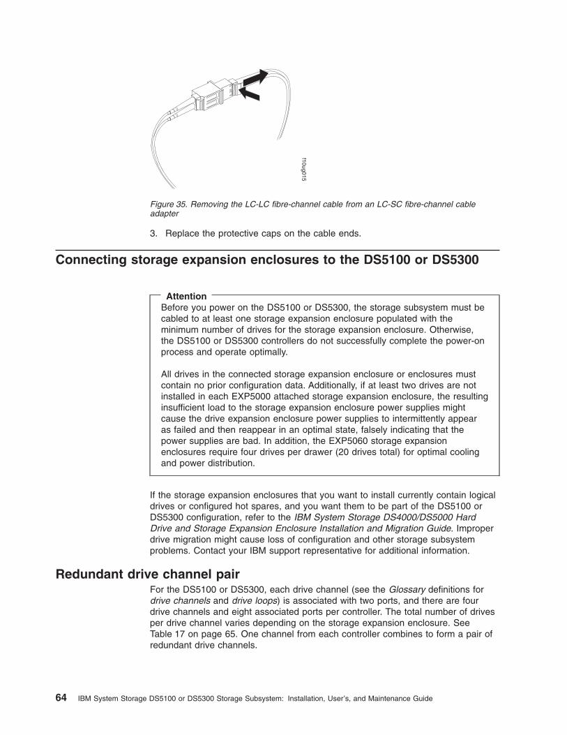
3. Replace the protective caps on the cable ends.
Connecting storage expansion enclosures to the DS5100 or DS5300
AttentionBefore you power on the DS5100 or DS5300, the storage subsystem must becabled to at least one storage expansion enclosure populated with theminimum number of drives for the storage expansion enclosure. Otherwise,the DS5100 or DS5300 controllers do not successfully complete the power-onprocess and operate optimally.
All drives in the connected storage expansion enclosure or enclosures mustcontain no prior configuration data. Additionally, if at least two drives are notinstalled in each EXP5000 attached storage expansion enclosure, the resultinginsufficient load to the storage expansion enclosure power supplies mightcause the drive expansion enclosure power supplies to intermittently appearas failed and then reappear in an optimal state, falsely indicating that thepower supplies are bad. In addition, the EXP5060 storage expansionenclosures require four drives per drawer (20 drives total) for optimal coolingand power distribution.
If the storage expansion enclosures that you want to install currently contain logicaldrives or configured hot spares, and you want them to be part of the DS5100 orDS5300 configuration, refer to the IBM System Storage DS4000/DS5000 HardDrive and Storage Expansion Enclosure Installation and Migration Guide. Improperdrive migration might cause loss of configuration and other storage subsystemproblems. Contact your IBM support representative for additional information.
Redundant drive channel pairFor the DS5100 or DS5300, each drive channel (see the Glossary definitions fordrive channels and drive loops) is associated with two ports, and there are fourdrive channels and eight associated ports per controller. The total number of drivesper drive channel varies depending on the storage expansion enclosure. SeeTable 17 on page 65. One channel from each controller combines to form a pair ofredundant drive channels.
f10ug015
Figure 35. Removing the LC-LC fibre-channel cable from an LC-SC fibre-channel cableadapter
64 IBM System Storage DS5100 or DS5300 Storage Subsystem: Installation, User’s, and Maintenance Guide

Table 17. Maximum number of drives per drive channel by enclosure type
Storage expansionenclosure Maximum number of drives
Number of storageexpansion enclosures
EXP5000 112 7 EXP5000
EXP5060 120 2 EXP5060
EXP5000 and EXP5060 108 1 EXP5060 and 3 EXP5000
In Figure 36, drive channel 1 of controller A and drive channel 5 of controller Bcombine to form a DS5100 or DS5300 drive channel pair. If any component of drivechannel 1 fails, the RAID controllers can still access the storage expansionenclosures in drive channel 1 through drive channel 5. Similarly, drive channel 2 ofcontroller A and drive channel 6 of controller B combine to form the second of thetwo DS5100 or DS5300 drive channel pairs. If any component of drive channel 2fails, the RAID controllers can still access the storage expansion enclosures in drivechannel 2 through drive channel 6.
Figure 36 shows the storage expansion enclosures in each drive channel pairsconnected to only one drive port in the two-ported drive channel. For example, indrive channel pair 1, only port 8 of channel 1 and port 1 of channel 5 are used.
Note: In the following drive cabling figure, the DS5100 or DS5300 graphic issimplified to show only the drive ports of each controller. The storageexpansion enclosures are simplified to show only the ESM FC ports.
Non-trunking cablingNon-trunking cabling is the cabling scheme where the controller drive ports areconnected to the EXP5000 or EXP5060 drive channel ports labeled 1B on bothESMs of the EXP5000 or EXP5060 storage expansion enclosures, forming a pair ofredundant connections between the storage subsystem and the storage expansionenclosure. This is the cabling that is supported when intermixing the EXP5060 andEXP5000 or EXP810 storage expansion enclosures behind the same drive channelor drive channel port.
ds50075
Left ESM
Left ESMLeft ESM Right ESM
Right ESM
DS5000 Controller A
DS5000 Controller B
Redundant drive
channel pair 1
Figure 36. Example of redundant drive channel pairs
Chapter 3. Cabling the storage subsystem 65

Figure 37 shows an example of a DS5100/DS5300 storage subsystem that iscabled to two EXP5000s using a non-trunking cabling scheme. P8 and P6 ofcontroller A are connected to EXP5000 ESM A drive channel ports label 1B.Similarly, the storage subsystem drive ports P1 and P3 of controller B areconnected to the EXP5000 ESM B drive channel ports labeled 1B.
Figure 38 shows an example of a DS5100/DS5300 subsystem that is cabled to twoEXP5060s using a non-trunking cabling scheme. The storage subsystem drive portsP8 and P6 of controller A are connected to EXP5060 ESM A drive channel portslabel 1B. Similarly, the storage subsystem drive ports P1 and P3 of controller B areconnected to the EXP5060 ESM B drive channel ports labeled 1B.
The EXP5060 storage expansion enclosure requires firmware version 7.60.13.05, orhigher.
Port 1A of the EXP5000 or EXP5060 ESMs are used to connect more than oneEXP5000 or EXP5060 enclosure behind a storage subsystem controller drive port.Figure 39 on page 67 shows an example of a DS5100/DS5300 subsystem that iscabled to two EXP5000s behind the same DS5100/DS5300 drive channel portusing a non-trunking cabling scheme.
3 6
63
EXP810/EXP5000 3 6
63
EXP810/EXP5000
ds50083
21
Figure 37. One DS5100 or DS5300 and two EXP5000 storage expansion enclosures using anon-trunking cabling scheme
1A 1B
1A 1B
2A 2B
2A 2B
ESM A
ESM B
Ch5 Ch6 Ch7 Ch8
Ch1 Ch2 Ch3 Ch4
P8 P7 P6 P5 P4 P3 P2 P1
P8P7P6P5P4P3P2P1
1A 1B
1A 1B
2A 2B
2A 2B
ESM A
ESM B
Figure 38. Example of EXP5060 storage expansion enclosure with non-trunking cabling
66 IBM System Storage DS5100 or DS5300 Storage Subsystem: Installation, User’s, and Maintenance Guide
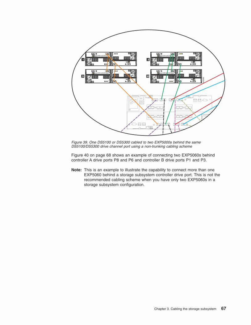
Figure 40 on page 68 shows an example of connecting two EXP5060s behindcontroller A drive ports P8 and P6 and controller B drive ports P1 and P3.
Note: This is an example to illustrate the capability to connect more than oneEXP5060 behind a storage subsystem controller drive port. This is not therecommended cabling scheme when you have only two EXP5060s in astorage subsystem configuration.
3 6
63
EXP810/EXP5000
21
3 6
63
EXP810/EXP5000
9 10
3 6
63
EXP810/EXP5000
3 6
63
EXP810/EXP5000
ds50086
Figure 39. One DS5100 or DS5300 cabled to two EXP5000s behind the sameDS5100/DS5300 drive channel port using a non-trunking cabling scheme
Chapter 3. Cabling the storage subsystem 67
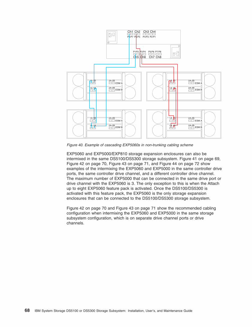
EXP5060 and EXP5000/EXP810 storage expansion enclosures can also beintermixed in the same DS5100/DS5300 storage subsystem. Figure 41 on page 69,Figure 42 on page 70, Figure 43 on page 71, and Figure 44 on page 72 showexamples of the intermixing the EXP5060 and EXP5000 in the same controller driveports, the same controller drive channel, and a different controller drive channel.The maximum number of EXP5000 that can be connected in the same drive port ordrive channel with the EXP5060 is 3. The only exception to this is when the Attachup to eight EXP5060 feature pack is activated. Once the DS5100/DS5300 isactivated with this feature pack, the EXP5060 is the only storage expansionenclosures that can be connected to the DS5100/DS5300 storage subsystem.
Figure 42 on page 70 and Figure 43 on page 71 show the recommended cablingconfiguration when intermixing the EXP5060 and EXP5000 in the same storagesubsystem configuration, which is on separate drive channel ports or drivechannels.
Ch5 Ch6 Ch7 Ch8
Ch1 Ch2 Ch3 Ch4
P8 P7 P6 P5 P4 P3 P2 P1
P8P7P6P5P4P3P2P1
1A 1B
1A 1B
2A 2B
2A 2B
ESM A
ESM B
1A 1B
1A 1B
2A 2B
2A 2B
ESM A
ESM B
1A 1B
1A 1B
2A 2B
2A 2B
ESM A
ESM B
1A 1B
1A 1B
2A 2B
2A 2B
ESM A
ESM B
Figure 40. Example of cascading EXP5060s in non-trunking cabling scheme
68 IBM System Storage DS5100 or DS5300 Storage Subsystem: Installation, User’s, and Maintenance Guide

1B1A 2B 2A
1B 1A
1B1A 2B 2A
1B 1A
1B1A 2B 2A
1B 1A
1A 1B
1A 1B
2A 2B
2A 2B
ESM A
ESM B
Ch5 Ch6 Ch7 Ch8
Ch1 Ch2 Ch3 Ch4
P8 P7 P6 P5 P4 P3 P2 P1
P8P7P6P5P4P3P2P1
Figure 41. Preferred EXP5060 and EXP5000 intermixing behind the same controller drivechannel port
Chapter 3. Cabling the storage subsystem 69

1B1A 2B 2A
1B 1A
1B1A 2B 2A
1B 1A
1B1A 2B 2A
1B 1A
1A 1B
1A 1B
2A 2B
2A 2B
ESM A
ESM B
Ch5 Ch6 Ch7 Ch8
Ch1 Ch2 Ch3 Ch4
P8 P7 P6 P5 P4 P3 P2 P1
P8P7P6P5P4P3P2P1
Figure 42. EXP5060 and EXP5000 intermixing behind the same controller drive channel port
70 IBM System Storage DS5100 or DS5300 Storage Subsystem: Installation, User’s, and Maintenance Guide
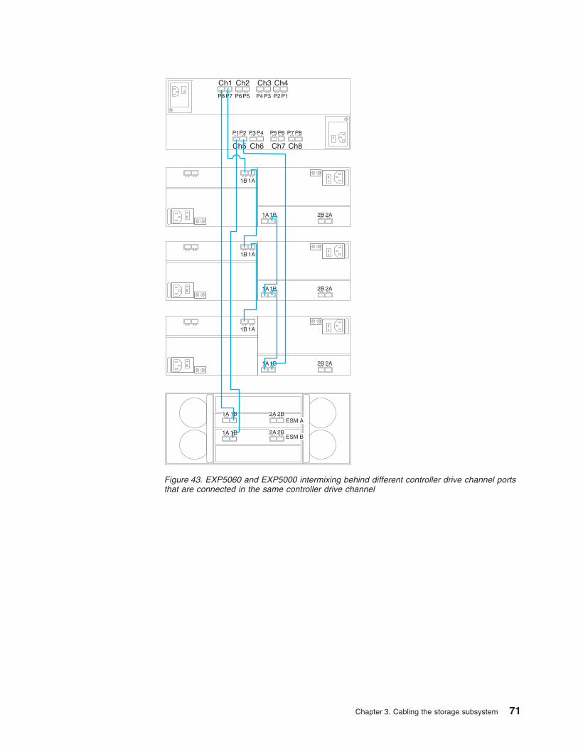
1B1A 2B 2A
1B 1A
1B1A 2B 2A
1B 1A
1B1A 2B 2A
1B 1A
1A 1B
1A 1B
2A 2B
2A 2B
ESM A
ESM B
Ch5 Ch6 Ch7 Ch8
Ch1 Ch2 Ch3 Ch4
P8 P7 P6 P5 P4 P3 P2 P1
P8P7P6P5P4P3P2P1
Figure 43. EXP5060 and EXP5000 intermixing behind different controller drive channel portsthat are connected in the same controller drive channel
Chapter 3. Cabling the storage subsystem 71

1B1A 2B 2A
1B 1A
1B1A 2B 2A
1B 1A
1B1A 2B 2A
1B 1A
1B1A 2B 2A
1B 1A
1B1A 2B 2A
1B 1A
1B1A 2B 2A
1B 1A
1B1A 2B 2A
1B 1A
1A 1B
1A 1B
2A 2B
2A 2B
ESM A
ESM B
Ch5 Ch6 Ch7 Ch8
Ch1 Ch2 Ch3 Ch4
P8 P7 P6 P5 P4 P3 P2 P1
P8P7P6P5P4P3P2P1
Figure 44. EXP5060 and EXP5000 in different controller drive channels
72 IBM System Storage DS5100 or DS5300 Storage Subsystem: Installation, User’s, and Maintenance Guide
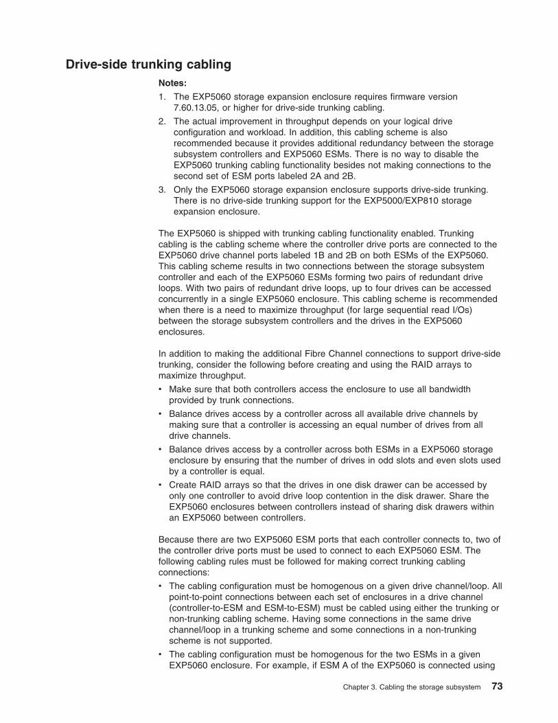
Drive-side trunking cablingNotes:
1. The EXP5060 storage expansion enclosure requires firmware version7.60.13.05, or higher for drive-side trunking cabling.
2. The actual improvement in throughput depends on your logical driveconfiguration and workload. In addition, this cabling scheme is alsorecommended because it provides additional redundancy between the storagesubsystem controllers and EXP5060 ESMs. There is no way to disable theEXP5060 trunking cabling functionality besides not making connections to thesecond set of ESM ports labeled 2A and 2B.
3. Only the EXP5060 storage expansion enclosure supports drive-side trunking.There is no drive-side trunking support for the EXP5000/EXP810 storageexpansion enclosure.
The EXP5060 is shipped with trunking cabling functionality enabled. Trunkingcabling is the cabling scheme where the controller drive ports are connected to theEXP5060 drive channel ports labeled 1B and 2B on both ESMs of the EXP5060.This cabling scheme results in two connections between the storage subsystemcontroller and each of the EXP5060 ESMs forming two pairs of redundant driveloops. With two pairs of redundant drive loops, up to four drives can be accessedconcurrently in a single EXP5060 enclosure. This cabling scheme is recommendedwhen there is a need to maximize throughput (for large sequential read I/Os)between the storage subsystem controllers and the drives in the EXP5060enclosures.
In addition to making the additional Fibre Channel connections to support drive-sidetrunking, consider the following before creating and using the RAID arrays tomaximize throughput.
v Make sure that both controllers access the enclosure to use all bandwidthprovided by trunk connections.
v Balance drives access by a controller across all available drive channels bymaking sure that a controller is accessing an equal number of drives from alldrive channels.
v Balance drives access by a controller across both ESMs in a EXP5060 storageenclosure by ensuring that the number of drives in odd slots and even slots usedby a controller is equal.
v Create RAID arrays so that the drives in one disk drawer can be accessed byonly one controller to avoid drive loop contention in the disk drawer. Share theEXP5060 enclosures between controllers instead of sharing disk drawers withinan EXP5060 between controllers.
Because there are two EXP5060 ESM ports that each controller connects to, two ofthe controller drive ports must be used to connect to each EXP5060 ESM. Thefollowing cabling rules must be followed for making correct trunking cablingconnections:
v The cabling configuration must be homogenous on a given drive channel/loop. Allpoint-to-point connections between each set of enclosures in a drive channel(controller-to-ESM and ESM-to-ESM) must be cabled using either the trunking ornon-trunking cabling scheme. Having some connections in the same drivechannel/loop in a trunking scheme and some connections in a non-trunkingscheme is not supported.
v The cabling configuration must be homogenous for the two ESMs in a givenEXP5060 enclosure. For example, if ESM A of the EXP5060 is connected using
Chapter 3. Cabling the storage subsystem 73
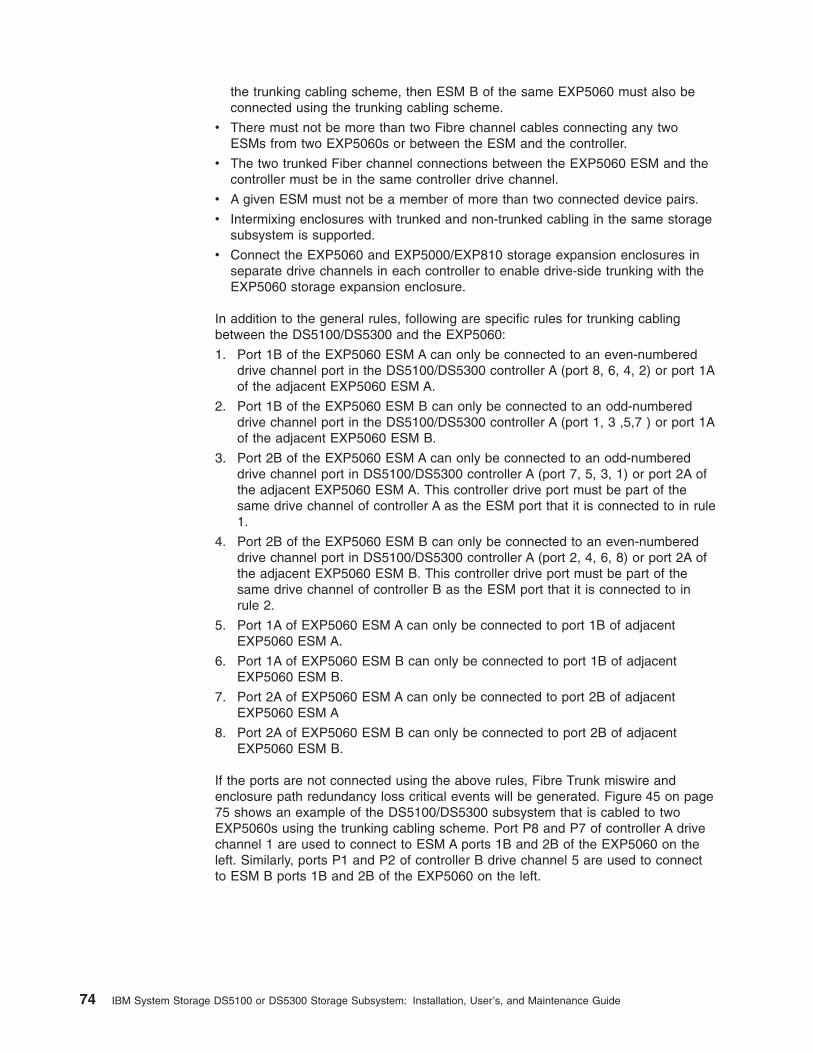
the trunking cabling scheme, then ESM B of the same EXP5060 must also beconnected using the trunking cabling scheme.
v There must not be more than two Fibre channel cables connecting any twoESMs from two EXP5060s or between the ESM and the controller.
v The two trunked Fiber channel connections between the EXP5060 ESM and thecontroller must be in the same controller drive channel.
v A given ESM must not be a member of more than two connected device pairs.
v Intermixing enclosures with trunked and non-trunked cabling in the same storagesubsystem is supported.
v Connect the EXP5060 and EXP5000/EXP810 storage expansion enclosures inseparate drive channels in each controller to enable drive-side trunking with theEXP5060 storage expansion enclosure.
In addition to the general rules, following are specific rules for trunking cablingbetween the DS5100/DS5300 and the EXP5060:
1. Port 1B of the EXP5060 ESM A can only be connected to an even-numbereddrive channel port in the DS5100/DS5300 controller A (port 8, 6, 4, 2) or port 1Aof the adjacent EXP5060 ESM A.
2. Port 1B of the EXP5060 ESM B can only be connected to an odd-numbereddrive channel port in the DS5100/DS5300 controller A (port 1, 3 ,5,7 ) or port 1Aof the adjacent EXP5060 ESM B.
3. Port 2B of the EXP5060 ESM A can only be connected to an odd-numbereddrive channel port in DS5100/DS5300 controller A (port 7, 5, 3, 1) or port 2A ofthe adjacent EXP5060 ESM A. This controller drive port must be part of thesame drive channel of controller A as the ESM port that it is connected to in rule1.
4. Port 2B of the EXP5060 ESM B can only be connected to an even-numbereddrive channel port in DS5100/DS5300 controller A (port 2, 4, 6, 8) or port 2A ofthe adjacent EXP5060 ESM B. This controller drive port must be part of thesame drive channel of controller B as the ESM port that it is connected to inrule 2.
5. Port 1A of EXP5060 ESM A can only be connected to port 1B of adjacentEXP5060 ESM A.
6. Port 1A of EXP5060 ESM B can only be connected to port 1B of adjacentEXP5060 ESM B.
7. Port 2A of EXP5060 ESM A can only be connected to port 2B of adjacentEXP5060 ESM A
8. Port 2A of EXP5060 ESM B can only be connected to port 2B of adjacentEXP5060 ESM B.
If the ports are not connected using the above rules, Fibre Trunk miswire andenclosure path redundancy loss critical events will be generated. Figure 45 on page75 shows an example of the DS5100/DS5300 subsystem that is cabled to twoEXP5060s using the trunking cabling scheme. Port P8 and P7 of controller A drivechannel 1 are used to connect to ESM A ports 1B and 2B of the EXP5060 on theleft. Similarly, ports P1 and P2 of controller B drive channel 5 are used to connectto ESM B ports 1B and 2B of the EXP5060 on the left.
74 IBM System Storage DS5100 or DS5300 Storage Subsystem: Installation, User’s, and Maintenance Guide
Figure 46 shows an example of improperly wired trunking. This example shows aviolation of trunking cabling rule 3, that port 2B of EXP5060 ESM A can only beconnected to an odd-numbered drive channel port in DS5100/DS5300 controller A(port 7, 5, 3, 1). This controller drive port must be part of the same drive channel ofcontroller A as the ESM port is connected to in rule 1. As shown in Figure 46, port2B of ESM A is incorrectly connected to port 5 of drive channel 2 instead port 7 ofdrive channel 1.
Cascading the EXP5060 behind a drive channel is also supported using thetrunking cabling scheme. However, the two cascaded EXP5060s will have only fourpossible data paths to access the drives in their enclosures instead of eight datapaths as in the non-cascaded trunking cabling scheme with two EXP5060s.Figure 47 on page 76 shows an example of cascading EXP5060s in the trunkingcabling scheme.
Ch5 Ch6 Ch7 Ch8
Ch1 Ch2 Ch3 Ch4
P8 P7 P6 P5 P4 P3 P2 P1
P8P7P6P5P4P3P2P1
1A 1B
1A 1B
2A 2B
2A 2B
ESM A
ESM B
1A 1B
1A 1B
2A 2B
2A 2B
ESM A
ESM B
Figure 45. EXP5060 in trunking cabling scheme
Ch5 Ch6 Ch7 Ch8
Ch1 Ch2 Ch3 Ch4
P8 P7 P6 P5 P4 P3 P2 P1
P8P7P6P5P4P3P2P1
1A 1B
1A 1B
2A 2B
2A 2B
ESM A
ESM B
Figure 46. An example of trunking cabling that is improperly wired
Chapter 3. Cabling the storage subsystem 75

The trunking cabling scheme is supported for EXP5060s behind a controller drivechannel only. It is not supported when intermixing EXP5000 and EXP5060s behinda drive channel. A trunk incompatible ESM critical event will be generated if you tryto cable the EXP5060 to the EXP5000 using the trunking cabling scheme.
Overview of steps to connect storage expansion enclosure to astorage subsystem
To connect storage expansion enclosures to the storage subsystem, perform thefollowing steps:
Note: The following procedures are for cold-case procedures (in which the DS5100or DS5300 is powered down when storage expansion enclosures areconnected, as in the case of initial installation). For hot-case procedures (inwhich the DS5100 or DS5300 is powered on when storage expansionenclosures are connected), refer to the IBM System StorageDS4000/DS5000 Hard Drive and Storage Expansion Enclosure Installationand Migration Guide.
1. Follow the instructions in the Installation, User's, and Maintenance Guide foryour specific storage expansion enclosure, for setting up and mounting thestorage expansion enclosures.
2. Select a cabling topology appropriate for the number of storage expansionenclosures you will connect to the DS5100 or DS5300. (You must connect atleast one storage expansion enclosure, populated with at least two drives,before you power on the DS5100 or DS5300.)
“DS5100 or DS5300 drive cabling topologies” on page 81 describes theschemes for cabling different numbers of storage expansion enclosures to theDS5100 or DS5300 and to each other (that is, if you are connecting more thanone storage expansion enclosure).
1A 1B
1A 1B
2A 2B
2A 2B
ESM A
ESM B
1A 1B
1A 1B
2A 2B
2A 2B
ESM A
ESM B
1A 1B
1A 1B
2A 2B
2A 2B
ESM A
ESM B
1A 1B
1A 1B
2A 2B
2A 2B
ESM A
ESM B
Ch5 Ch6 Ch7 Ch8
Ch1 Ch2 Ch3 Ch4
P8 P7 P6 P5 P4 P3 P2 P1
P8P7P6P5P4P3P2P1
Figure 47. Cascading EXP5060s in trunking cabling scheme
76 IBM System Storage DS5100 or DS5300 Storage Subsystem: Installation, User’s, and Maintenance Guide
The DS5100 or DS5300 locates the drives in the storage expansion enclosuresafter you power on the configuration. Always connect power to the storageexpansion enclosures first and then connect power to the DS5100 or DS5300. Afteryou have powered on the configuration, use the DS Storage Manager client tocheck the status of the new drives, correct any errors found, and configure the newdrives.
DS5100 or DS5300 drive cabling best practices and rulesAdd storage expansion enclosures to the DS5100 or DS5300 drive ports in around-robin fashion. For example, if you have four EXP5000s to be cabled to theDS5100 or DS5300, instead of cabling all four EXP5000s to one drive port of adrive channel, distribute the enclosures to all drive ports, which results in oneenclosure per drive port of a drive channel. Table 18 on page 78 and Table 19 onpage 78 show the number of storage expansion enclosures per port and drivechannel when connecting EXP5060 expansion enclosure to the DS5100/DS5300.Table 20 on page 78 shows the number of storage expansion enclosures per portand drive channel when connecting EXP5000 storage expansion enclosures to theDS5100/DS5300.
Chapter 3. Cabling the storage subsystem 77

Table 18. Number of EXP5060 storage expansion enclosures per port and drive channel (nontrunking cabling)
Number ofenclosures Channel 1 Channel 2 Channel 3 Channel 4 Table 19
Port 8 Port 7 Port 6 Port 5 Port 4 Port 3 Port2
Port 1 ControllerA
1 1 0 0 0 0 0 0 0
2 1 0 1 0 0 0 0 0
3 1 0 1 0 1 0 0 0
4 1 0 1 0 1 0 1 0
5 1 1 1 0 1 0 1 0
6 1 1 1 1 1 0 1 0
7 1 1 1 1 1 1 1 0
8 1 1 1 1 1 1 1 1
Port 1 Port 2 Port 3 Port 4 Port 5 Port 6 Port7
Port 8 ControllerB
Channel 5 Channel 6 Channel 7 Channel 8
Table 19. Number of EXP5060 storage expansion enclosures per port and drive channel(trunking cabling)
Number ofenclosures Channel 1 Channel 2 Channel 3 Channel 4
Port 8 Port 7 Port 6 Port 5 Port 4 Port 3 Port2
Port 1 ControllerA
1 1 1 0 0 0 0 0 0
2 1 1 1 1 0 0 0 0
3 1 1 1 1 1 1 0 0
4 1 1 1 1 1 1 1 1
5 2 2 1 1 1 1 1 1
6 2 2 2 2 1 0 1 0
7 2 2 2 2 2 2 1 1
8 2 2 2 2 2 2 2 2
Port 1 Port 2 Port 3 Port 4 Port 5 Port 6 Port7
Port 8 ControllerB
Channel 5 Channel 6 Channel 7 Channel 8
Table 20. Number of storage expansion enclosures per port and drive channel
Number ofenclosures Channel 1 Channel 2 Channel 3 Channel 4
Port 8 Port 7 Port 6 Port 5 Port 4 Port 3 Port2
Port 1 ControllerA
78 IBM System Storage DS5100 or DS5300 Storage Subsystem: Installation, User’s, and Maintenance Guide

Table 20. Number of storage expansion enclosures per port and drive channel (continued)
Number ofenclosures Channel 1 Channel 2 Channel 3 Channel 4
1 1 0 0 0 0 0 0 0
2 1 0 1 0 0 0 0 0
3 1 0 1 0 1 0 0 0
4 1 0 1 0 1 0 1 0
5 1 1 1 0 1 0 1 0
6 1 1 1 1 1 0 1 0
7 1 1 1 1 1 1 1 0
8 1 1 1 1 1 1 1 1
9 2 1 1 1 1 1 1 1
10 2 1 2 1 1 1 1 1
11 2 1 2 1 2 1 1 1
12 2 1 2 1 2 1 2 1
13 2 2 2 1 2 1 2 1
14 2 2 2 2 2 1 2 1
15 2 2 2 2 2 2 2 1
16 2 2 2 2 2 2 2 2
17 3 2 2 2 2 2 2 2
18 3 2 3 2 2 2 2 2
19 3 2 3 2 3 2 2 2
20 3 2 3 2 3 2 3 2
21 3 3 3 2 3 2 3 2
22 3 3 3 3 3 2 3 2
23 3 3 3 3 3 3 3 2
24 3 3 3 3 3 3 3 3
25 4 3 3 3 3 3 3 3
26 4 3 4 3 3 3 3 3
27 4 3 4 3 4 3 3 3
28 4 3 4 3 4 3 4 3
Port 1 Port 2 Port 3 Port 4 Port 5 Port 6 Port7
Port 8 ControllerB
Channel 5 Channel 6 Channel 7 Channel 8
EXP5000 storage expansion enclosure cabling rulesRefer to these general rules when cabling the storage subsystem to the EXP5000storage expansion enclosure.
1. Do not connect a combination of more than seven EXP5000 storage expansionenclosures to the two ports of a dual-ported drive channel. Failure to observethis limitation might result in loss of data availability.
2. Do not connect more than four EXP5000 storage expansion enclosures to anyport of a dual-ported drive channel.
Chapter 3. Cabling the storage subsystem 79

3. The DS5100 or DS5300 controller drive port must always be connected to theEXP5000 port labeled 1B. Because the left and right EXP5000 ESMs (ESMs Aand B) are inserted in the ESM bays in different orientations, you must look forthe port labeled 1B before making the fibre channel connections. Figure 48shows the port labels on the EXP5000.
4. The EXP5000 does not support drive-side trunking. Do not make anyconnections to port 2A and 2B of the EXP5000 ESM ports.
EXP5060 storage expansion enclosure cabling rulesRefer to these general rules when cabling the storage subsystem to the EXP5060storage expansion enclosure.
1. Do not connect a combination of more than two EXP5060 storage expansionenclosures to the two ports of a dual-ported drive channel. Failure to observethis limitation might result in loss of data availability.
Note: Maximum configuration requires purchase of an Attached up to eightEXP5060 feature pack.
2. Do not connect more than two EXP5060 storage expansion enclosures to anyport of a dual-ported drive channel.
3. The DS5100 or DS5300 controller drive port must always be connected to theEXP5060 ESM port labeled 1B in non-trunking configurations and EXP5060ESM ports labels 1B and 2B in drive-side trunking configurations. Figure 49shows the port labels on the EXP5060.
ds50077
1A1B
1A 1B
Figure 48. EXP5000 port labels
1A 1B 2A 2B
1A 1B 2A 2B
ESM B
ESM A
Figure 49. EXP5060 port labels
80 IBM System Storage DS5100 or DS5300 Storage Subsystem: Installation, User’s, and Maintenance Guide

4. Intermixing enclosures with trunked and non-trunked cabling in the samestorage subsystem is supported.
5. See “Drive-side trunking cabling” on page 73 and review the rules andconsiderations.
6. Do not cable the EXP5060 storage expansion enclosures in a cascadingscheme unless all drive channel ports are used to support the additionalEXP5060s.
7. Connect the EXP5060 and EXP5000/EXP810 storage expansion enclosures inseparate drive channels in each controller to enable drive-side trunking with theEXP5060 storage expansion enclosure.
DS5100 or DS5300 drive cabling topologiesThe following sections provide preferred cabling topologies for cabling storageexpansion enclosures to the DS5100 or DS5300. Each example provides redundantpaths to the drives. If one of these examples is suitable for your hardware andapplication, complete the cabling connections as described in the tables. If youhave hardware to include in your topology other than what is shown in theseexamples, use the examples as a starting point for creating your specific topology.
Attention: For the maximum number of storage expansion enclosures supportedper redundant drive channel pair, see Table 3 on page 9.
If you are using fiber-optic cables, install SFP modules into the ports that willreceive the cables before installing the cables.
Figure 50 on page 82 and Figure 51 on page 83 show the locations of controllers Aand B, the single-ported Fibre Channel host channels, single-ported iSCSI hostchannels, Ethernet ports, and dual-ported drive channels, at the back of theDS5100 or DS5300.
Chapter 3. Cabling the storage subsystem 81

1 1
1
1
1
2 2
2
2
2
3
3
3
4
1234
4
4
Controller A
Controller B
Drive ports
Drive portsEthernet ports
Ethernet ports
Drive channel4
Drive channel5
5678
5 6 7 8
Drive channel6
Drive channel7
Drive channel8
Drive channel1
Drive channel2
Drive channel3
1234
1 2 3 4
Fibre Channel host portsFibre Channel host ports
Figure 50. DS5100 or DS5300 ports and controllers with Fibre Channel host connections
82 IBM System Storage DS5100 or DS5300 Storage Subsystem: Installation, User’s, and Maintenance Guide

Table 21 provides a list of the drive channels that are associated with each of thecontroller drive ports.
Table 21. DS5100 or DS5300 drive ports and drive channels
Drive Channel Number Controller Drive Port Numbers
1 A 8 and 7
2 A 6 and 5
3 A 4 and 3
4 A 2 and 1
5 B 1 and 2
6 B 3 and 4
7 B 5 and 6
8 B 7 and 8
Note: In the following drive cabling figures, the DS5100 or DS5300 graphics aresimplified to show only the drive ports of each controller. In addition, thestorage expansion enclosures are simplified to show only the ESM FC ports.
The following sections show some of the supported cabling configurations.
v “One DS5100 or DS5300 and one EXP5000 storage expansion enclosure” onpage 84
v “One DS5100 or DS5300 and two EXP5000 storage expansion enclosures” onpage 85
1 1
1
1
1
2 2
2
2
2
3
3
4
4
Controller A
Controller B
iSCSI host ports
Drive ports
Drive portsEthernet ports
Ethernet ports
Drive channel4
Drive channel5
5678
5 6 7 8
Drive channel6
Drive channel7
Drive channel8
Drive channel1
Drive channel2
Drive channel3
12
1 2
12
iSCSI host ports
Figure 51. DS5100 or DS5300 ports and controllers with iSCSI host connections
Chapter 3. Cabling the storage subsystem 83

v “One DS5100 or DS5300 and four EXP5000 storage expansion enclosures” onpage 86
v “One DS5100 or DS5300 and eight EXP5000 storage expansion enclosures” onpage 86
v “One DS5100 or DS5300 and sixteen EXP5000 storage expansion enclosures”on page 88
v “One DS5100 or DS5300 and one EXP5060 storage expansion enclosure” onpage 106
v “One DS5100 or DS5300 and two EXP5060 storage expansion enclosures” onpage 106
v “One DS5100 or DS5300 and three EXP5060 storage expansion enclosures” onpage 107
v “One DS5100 or DS5300 and four EXP5060 storage expansion enclosures” onpage 108
v “One DS5100 or DS5300 and eight EXP5060 storage expansion enclosures” onpage 110
v “One DS5100 or DS5300 and one EXP5060 intermixed with a maximum of threeEXP810/EXP5000 storage expansion enclosures” on page 112
v “DS5100 or DS5300 storage subsystem and one EXP5060 intermixed with amaximum of seven EXP810/EXP5000 storage expansion enclosures” on page116
The following sections show some of the supported drive-side trunking cablingconfigurations.
v “One storage subsystem and one EXP5060 storage expansion enclosure” onpage 117
v “One storage subsystem and two EXP5060 storage expansion enclosures” onpage 118
v “One storage subsystem and four EXP5060 storage expansion enclosures” onpage 119
v “One storage subsystem and eight EXP5060 storage expansion enclosures” onpage 121
Note: The cabling schemes in this section are not all inclusive and do not showevery possible cabling scenario. Use the schemes as guidance, along withrules and best practices in “DS5100 or DS5300 drive cabling best practicesand rules” on page 77 as well as Table 20 on page 78, to cable yourDS5100 or DS5300 and EXP5000s.
One DS5100 or DS5300 and one EXP5000 storage expansionenclosureIf you are cabling one DS5100 or DS5300 to one EXP5000 storage expansionenclosure, Figure 52 on page 85 shows the cabling scheme.
84 IBM System Storage DS5100 or DS5300 Storage Subsystem: Installation, User’s, and Maintenance Guide

Table 22 describes Figure 52.
Table 22. Description of the figure that shows the DS5100 or DS5300 and one EXP5000storage expansion enclosure
Number Description
1 Drive channel 1
3 Drive channel 5
2 Storage expansion enclosure 1
1. To create drive channel 1, connect drive port 8 of controller A to port 1B on theleft ESM of enclosure 1 (1).
2. To create drive channel 5, connect drive port 1 of controller B to port 1B on theright ESM of enclosure 1 (3).
One DS5100 or DS5300 and two EXP5000 storage expansionenclosuresFigure 53 shows the cabling scheme for one DS5100 or DS5300 and two EXP5000storage expansion enclosures.
Perform the following steps to connect two EXP5000 storage expansion enclosuresto one DS5100 or DS5300:
1. Connect port 8 of drive channel 1 on the DS5100 or DS5300 to port 1B on theleft ESM of the first EXP5000 (1).
2. Connect port 1 of drive channel 5 on the DS5100 or DS5300 to port 1B on theright ESM of the first EXP5000 (1).
ds50
0521 3
2
Figure 52. One DS5100 or DS5300 and one EXP5000 storage expansion enclosure
3 6
63
EXP810/EXP5000 3 6
63
EXP810/EXP5000
ds50083
21
Figure 53. One DS5100 or DS5300 and two EXP5000 storage expansion enclosures
Chapter 3. Cabling the storage subsystem 85
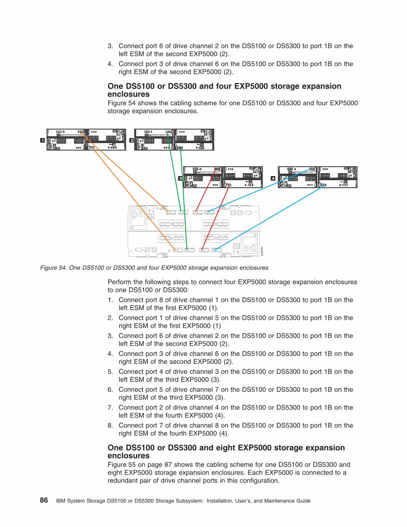
3. Connect port 6 of drive channel 2 on the DS5100 or DS5300 to port 1B on theleft ESM of the second EXP5000 (2).
4. Connect port 3 of drive channel 6 on the DS5100 or DS5300 to port 1B on theright ESM of the second EXP5000 (2).
One DS5100 or DS5300 and four EXP5000 storage expansionenclosuresFigure 54 shows the cabling scheme for one DS5100 or DS5300 and four EXP5000storage expansion enclosures.
Perform the following steps to connect four EXP5000 storage expansion enclosuresto one DS5100 or DS5300:
1. Connect port 8 of drive channel 1 on the DS5100 or DS5300 to port 1B on theleft ESM of the first EXP5000 (1).
2. Connect port 1 of drive channel 5 on the DS5100 or DS5300 to port 1B on theright ESM of the first EXP5000 (1)
3. Connect port 6 of drive channel 2 on the DS5100 or DS5300 to port 1B on theleft ESM of the second EXP5000 (2).
4. Connect port 3 of drive channel 6 on the DS5100 or DS5300 to port 1B on theright ESM of the second EXP5000 (2).
5. Connect port 4 of drive channel 3 on the DS5100 or DS5300 to port 1B on theleft ESM of the third EXP5000 (3).
6. Connect port 5 of drive channel 7 on the DS5100 or DS5300 to port 1B on theright ESM of the third EXP5000 (3).
7. Connect port 2 of drive channel 4 on the DS5100 or DS5300 to port 1B on theleft ESM of the fourth EXP5000 (4).
8. Connect port 7 of drive channel 8 on the DS5100 or DS5300 to port 1B on theright ESM of the fourth EXP5000 (4).
One DS5100 or DS5300 and eight EXP5000 storage expansionenclosuresFigure 55 on page 87 shows the cabling scheme for one DS5100 or DS5300 andeight EXP5000 storage expansion enclosures. Each EXP5000 is connected to aredundant pair of drive channel ports in this configuration.
3
3 6
63
EXP810/EXP5000
ds50084
3 6
63
EXP810/EXP5000
3 6
63
EXP810/EXP5000
2
4
1
3 6
63
EXP810/EXP5000
Figure 54. One DS5100 or DS5300 and four EXP5000 storage expansion enclosures
86 IBM System Storage DS5100 or DS5300 Storage Subsystem: Installation, User’s, and Maintenance Guide

Perform the following steps to connect eight EXP5000 storage expansionenclosures to one DS5100 or DS5300:
1. Connect port 8 of drive channel 1 on the DS5100 or DS5300 to port 1B on theleft ESM of the first EXP5000 (1).
2. Connect port 1 of drive channel 5 on the DS5100 or DS5300 to port 1B on theright ESM of the first EXP5000 (1)
3. Connect port 6 of drive channel 2 on the DS5100 or DS5300 to port 1B on theleft ESM of the second EXP5000 (2).
4. Connect port 3 of drive channel 6 on the DS5100 or DS5300 to port 1B on theright ESM of the second EXP5000 (2).
5. Connect port 4 of drive channel 3 on the DS5100 or DS5300 to port 1B on theleft ESM of the third EXP5000 (3).
6. Connect port 5 of drive channel 7 on the DS5100 or DS5300 to port 1B on theright ESM of the third EXP5000 (3).
7. Connect port 2 of drive channel 4 on the DS5100 or DS5300 to port 1B on theleft ESM of the fourth EXP5000 (4).
8. Connect port 7 of drive channel 8 on the DS5100 or DS5300 to port 1B on theright ESM of the fourth EXP5000 (4).
9. Connect port 7 of drive channel 1 on the DS5100 or DS5300 to port 1B on theleft ESM of the fifth EXP5000 (5).
10. Connect port 2 of drive channel 5 on the DS5100 or DS5300 to port 1B on theright ESM of the fifth EXP5000 (5).
11. Connect port 5 of drive channel 2 on the DS5100 or DS5300 to port 1B on theleft ESM of the sixth EXP5000 (6).
3
3 6
63
EXP810/EXP5000
ds50085
3 6
63
EXP810/EXP5000
3 6
63
EXP810/EXP5000
2
4
1
3 6
63
EXP810/EXP5000
3 6
63
EXP810/EXP5000 3 6
63
EXP810/EXP5000
3 6
63
EXP810/EXP5000 3 6
63
EXP810/EXP5000
5 6
7 8
Figure 55. One DS5100 or DS5300 and eight EXP5000 storage expansion enclosures
Chapter 3. Cabling the storage subsystem 87

12. Connect port 4 of drive channel 6 on the DS5100 or DS5300 to port 1B on theright ESM of the sixth EXP5000 (6).
13. Connect port 3 of drive channel 3 on the DS5100 or DS5300 to port 1B on theleft ESM of the seventh EXP5000 (7).
14. Connect port 6 of drive channel 7 on the DS5100 or DS5300 to port 1B on theright ESM of the seventh EXP5000 (7).
15. Connect port 1 of drive channel 4 on the DS5100 or DS5300 to port 1B on theleft ESM of the eighth EXP5000 (8).
16. Connect port 8 of drive channel 8 on the DS5100 or DS5300 to port 1B on theright ESM of the eighth EXP5000 (8).
The end result is one EXP5000 per drive port on the DS5100 or DS5300.
One DS5100 or DS5300 and sixteen EXP5000 storage expansionenclosuresFigure 56 shows the cabling scheme for one DS5100 or DS5300 and sixteenEXP5000 storage expansion enclosures. The figure shows only a cross-section ofthe cabling scheme. Each redundant pair of drive channel ports in this configurationhas two EXP5000 expansion enclosures connected in a cascading scheme.
Perform the following steps to connect sixteen EXP5000 storage expansionenclosures to one DS5100 or DS5300:
1. Perform the steps in “One DS5100 or DS5300 and eight EXP5000 storageexpansion enclosures” on page 86.
The result is one EXP5000 per drive port on the DS5100 or DS5300.
2. Perform the steps to cascade or daisy-chain an additional EXP5000 to anexisting EXP5000:
a. Add the ninth EXP5000 after the first EXP5000 (see 9 in Figure 56.)
3 6
63
EXP810/EXP5000
21
3 6
63
EXP810/EXP5000
9 10
3 6
63
EXP810/EXP5000
3 6
63
EXP810/EXP5000
ds50086
Figure 56. One DS5100 or DS5300 and sixteen EXP5000 storage expansion enclosures
88 IBM System Storage DS5100 or DS5300 Storage Subsystem: Installation, User’s, and Maintenance Guide
b. Connect port 1A on the left ESM of the first EXP5000 (1) to port 1B on theleft ESM of the ninth EXP5000 (9).
c. Connect port 1B on the right ESM of the first EXP5000 (1) to port 1A on theright ESM of the ninth EXP5000 (9).
d. Move the connection between port 1B on the right ESM of the first EXP5000(1) and port 1 of drive channel 5 on the DS5100 or DS5300 to port 1B ofthe ninth EXP5000.
3. Repeat 2 on page 88 to connect the remainder of the EXP5000s to port 1B onthe right ESM of the ninth EXP5000 (9).
The end result is two EXP5000 storage expansion enclosures per redundantpair of drive channel ports for a total of 16 storage expansion enclosures.
Chapter 3. Cabling the storage subsystem 89
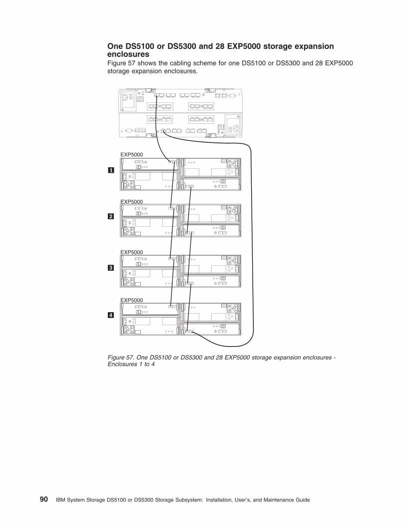
One DS5100 or DS5300 and 28 EXP5000 storage expansionenclosuresFigure 57 shows the cabling scheme for one DS5100 or DS5300 and 28 EXP5000storage expansion enclosures.
EXP5000
EXP5000
EXP5000
EXP5000
Figure 57. One DS5100 or DS5300 and 28 EXP5000 storage expansion enclosures -Enclosures 1 to 4
90 IBM System Storage DS5100 or DS5300 Storage Subsystem: Installation, User’s, and Maintenance Guide

Table 23. One DS5100 or DS5300 and 28 EXP5000 storage expansion enclosures - Enclosures 1 to 4
Cable
Controller A Controller BStorage ExpansionEnclosure 1
Ch1 Ch2 Ch3 Ch4 Ch5 Ch6 Ch7 Ch8ESM A(Left)
ESM B(Right)
8 7 6 5 4 3 2 1 1 2 3 4 5 6 7 8 1A 1B 1A 1B
1 X X
Cable
Storage Expansion Enclosure 1 Storage Expansion Enclosure 2
ESM A (Left) ESM B (Right) ESM A (Left) ESM B (Right)
1A 1B 1A 1B 1A 1B 1A 1B
2 X X
3 X X
Cable
Storage Expansion Enclosure 2 Storage Expansion Enclosure 3
ESM A (Left) ESM B (Right) ESM A (Left) ESM B (Right)
1A 1B 1A 1B 1A 1B 1A 1B
4 X X
5 X X
Cable
Storage Expansion Enclosure 3 Storage Expansion Enclosure 4
ESM A (Left) ESM B (Right) ESM A (Left) ESM B (Right)
1A 1B 1A 1B 1A 1B 1A 1B
6 X X
7 X X
Cable
Controller A Controller BStorage ExpansionEnclosure 4
Ch1 Ch2 Ch3 Ch4 Ch5 Ch6 Ch7 Ch8ESM A(Left)
ESM B(Right)
8 7 6 5 4 3 2 1 1 2 3 4 5 6 7 8 1A 1B 1A 1B
8 X X
Chapter 3. Cabling the storage subsystem 91
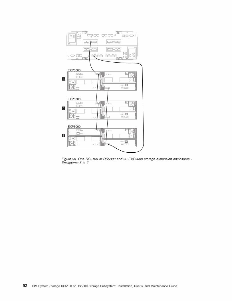
EXP5000
EXP5000
EXP5000
Figure 58. One DS5100 or DS5300 and 28 EXP5000 storage expansion enclosures -Enclosures 5 to 7
92 IBM System Storage DS5100 or DS5300 Storage Subsystem: Installation, User’s, and Maintenance Guide
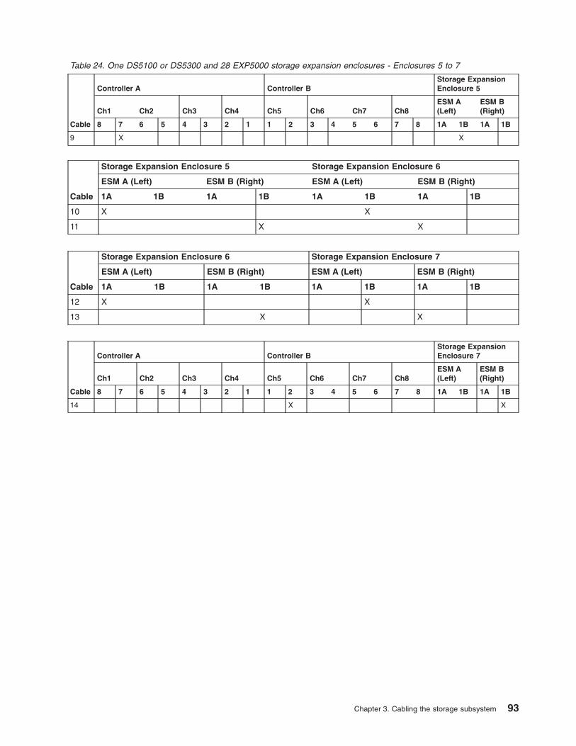
Table 24. One DS5100 or DS5300 and 28 EXP5000 storage expansion enclosures - Enclosures 5 to 7
Cable
Controller A Controller BStorage ExpansionEnclosure 5
Ch1 Ch2 Ch3 Ch4 Ch5 Ch6 Ch7 Ch8ESM A(Left)
ESM B(Right)
8 7 6 5 4 3 2 1 1 2 3 4 5 6 7 8 1A 1B 1A 1B
9 X X
Cable
Storage Expansion Enclosure 5 Storage Expansion Enclosure 6
ESM A (Left) ESM B (Right) ESM A (Left) ESM B (Right)
1A 1B 1A 1B 1A 1B 1A 1B
10 X X
11 X X
Cable
Storage Expansion Enclosure 6 Storage Expansion Enclosure 7
ESM A (Left) ESM B (Right) ESM A (Left) ESM B (Right)
1A 1B 1A 1B 1A 1B 1A 1B
12 X X
13 X X
Cable
Controller A Controller BStorage ExpansionEnclosure 7
Ch1 Ch2 Ch3 Ch4 Ch5 Ch6 Ch7 Ch8ESM A(Left)
ESM B(Right)
8 7 6 5 4 3 2 1 1 2 3 4 5 6 7 8 1A 1B 1A 1B
14 X X
Chapter 3. Cabling the storage subsystem 93

EXP5000
EXP5000
EXP5000
EXP5000
Figure 59. One DS5100 or DS5300 and 28 EXP5000 storage expansion enclosures -Enclosures 8 to 11
94 IBM System Storage DS5100 or DS5300 Storage Subsystem: Installation, User’s, and Maintenance Guide

Table 25. One DS5100 or DS5300 and 28 EXP5000 storage expansion enclosures - Enclosures 8 to 11
Cable
Controller A Controller BStorage ExpansionEnclosure 8
Ch1 Ch2 Ch3 Ch4 Ch5 Ch6 Ch7 Ch8ESM A(Left)
ESM B(Right)
8 7 6 5 4 3 2 1 1 2 3 4 5 6 7 8 1A 1B 1A 1B
15 X X
Cable
Storage Expansion Enclosure 8 Storage Expansion Enclosure 9
ESM A (Left) ESM B (Right) ESM A (Left) ESM B (Right)
1A 1B 1A 1B 1A 1B 1A 1B
16 X X
17 X X
Cable
Storage Expansion Enclosure 9 Storage Expansion Enclosure 10
ESM A (Left) ESM B (Right) ESM A (Left) ESM B (Right)
1A 1B 1A 1B 1A 1B 1A 1B
18 X X
19 X X
Cable
Storage Expansion Enclosure 10 Storage Expansion Enclosure 11
ESM A (Left) ESM B (Right) ESM A (Left) ESM B (Right)
1A 1B 1A 1B 1A 1B 1A 1B
20 X X
21 X X
Cable
Controller A Controller BStorage ExpansionEnclosure 11
Ch1 Ch2 Ch3 Ch4 Ch5 Ch6 Ch7 Ch8ESM A(Left)
ESM B(Right)
8 7 6 5 4 3 2 1 1 2 3 4 5 6 7 8 1A 1B 1A 1B
22 X X
Chapter 3. Cabling the storage subsystem 95

EXP5000
EXP5000
EXP5000
Figure 60. One DS5100 or DS5300 and 28 EXP5000 storage expansion enclosures -Enclosures 12 to 14
96 IBM System Storage DS5100 or DS5300 Storage Subsystem: Installation, User’s, and Maintenance Guide
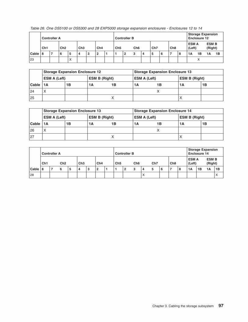
Table 26. One DS5100 or DS5300 and 28 EXP5000 storage expansion enclosures - Enclosures 12 to 14
Cable
Controller A Controller BStorage ExpansionEnclosure 12
Ch1 Ch2 Ch3 Ch4 Ch5 Ch6 Ch7 Ch8ESM A(Left)
ESM B(Right)
8 7 6 5 4 3 2 1 1 2 3 4 5 6 7 8 1A 1B 1A 1B
23 X X
Cable
Storage Expansion Enclosure 12 Storage Expansion Enclosure 13
ESM A (Left) ESM B (Right) ESM A (Left) ESM B (Right)
1A 1B 1A 1B 1A 1B 1A 1B
24 X X
25 X X
Cable
Storage Expansion Enclosure 13 Storage Expansion Enclosure 14
ESM A (Left) ESM B (Right) ESM A (Left) ESM B (Right)
1A 1B 1A 1B 1A 1B 1A 1B
26 X X
27 X X
Cable
Controller A Controller BStorage ExpansionEnclosure 14
Ch1 Ch2 Ch3 Ch4 Ch5 Ch6 Ch7 Ch8ESM A(Left)
ESM B(Right)
8 7 6 5 4 3 2 1 1 2 3 4 5 6 7 8 1A 1B 1A 1B
28 X X
Chapter 3. Cabling the storage subsystem 97
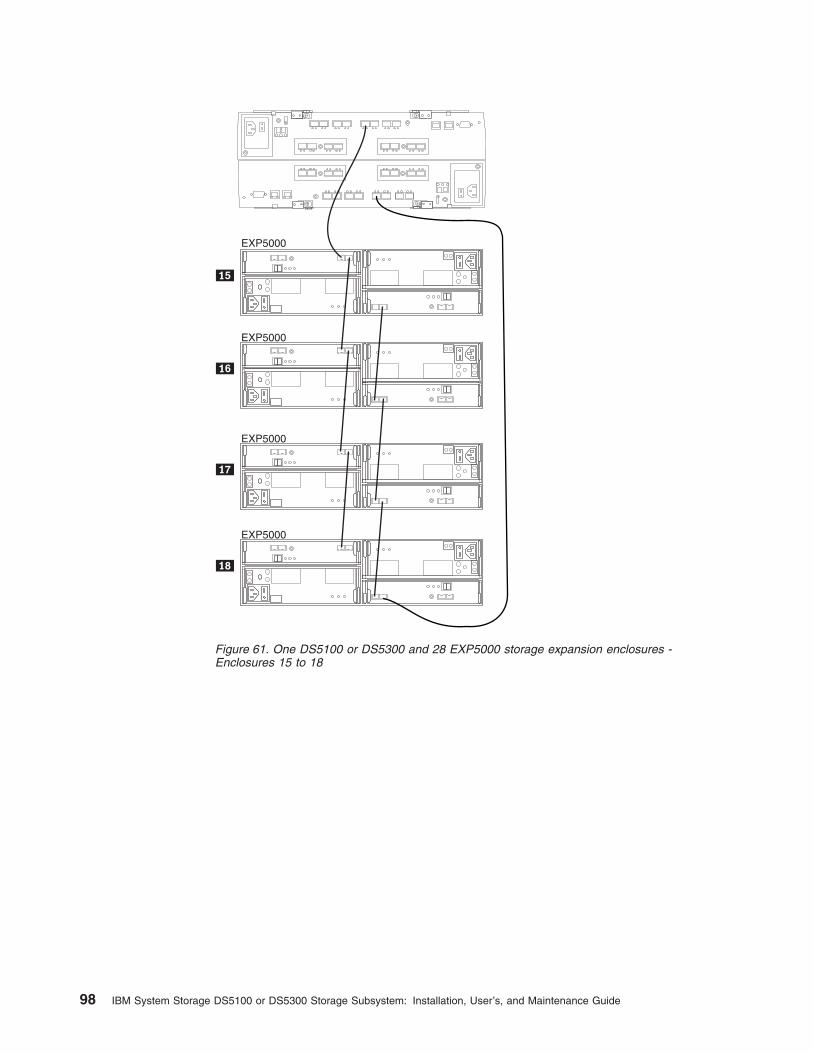
EXP5000
EXP5000
EXP5000
EXP5000
Figure 61. One DS5100 or DS5300 and 28 EXP5000 storage expansion enclosures -Enclosures 15 to 18
98 IBM System Storage DS5100 or DS5300 Storage Subsystem: Installation, User’s, and Maintenance Guide

Table 27. One DS5100 or DS5300 and 28 EXP5000 storage expansion enclosures - Enclosures 15 to 18
Cable
Controller A Controller BStorage ExpansionEnclosure 15
Ch1 Ch2 Ch3 Ch4 Ch5 Ch6 Ch7 Ch8ESM A(Left)
ESM B(Right)
8 7 6 5 4 3 2 1 1 2 3 4 5 6 7 8 1A 1B 1A 1B
29 X X
Cable
Storage Expansion Enclosure 15 Storage Expansion Enclosure 16
ESM A (Left) ESM B (Right) ESM A (Left) ESM B (Right)
1A 1B 1A 1B 1A 1B 1A 1B
30 X X
31 X X
Cable
Storage Expansion Enclosure 16 Storage Expansion Enclosure 17
ESM A (Left) ESM B (Right) ESM A (Left) ESM B (Right)
1A 1B 1A 1B 1A 1B 1A 1B
32 X X
33 X X
Cable
Storage Expansion Enclosure 17 Storage Expansion Enclosure 18
ESM A (Left) ESM B (Right) ESM A (Left) ESM B (Right)
1A 1B 1A 1B 1A 1B 1A 1B
34 X X
35 X X
Cable
Controller A Controller BStorage ExpansionEnclosure 18
Ch1 Ch2 Ch3 Ch4 Ch5 Ch6 Ch7 Ch8ESM A(Left)
ESM B(Right)
8 7 6 5 4 3 2 1 1 2 3 4 5 6 7 8 1A 1B 1A 1B
36 X X
Chapter 3. Cabling the storage subsystem 99

EXP5000
EXP5000
EXP5000
Figure 62. One DS5100 or DS5300 and 28 EXP5000 storage expansion enclosures -Enclosures 19 to 21
100 IBM System Storage DS5100 or DS5300 Storage Subsystem: Installation, User’s, and Maintenance Guide
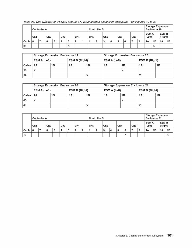
Table 28. One DS5100 or DS5300 and 28 EXP5000 storage expansion enclosures - Enclosures 19 to 21
Cable
Controller A Controller BStorage ExpansionEnclosure 19
Ch1 Ch2 Ch3 Ch4 Ch5 Ch6 Ch7 Ch8ESM A(Left)
ESM B(Right)
8 7 6 5 4 3 2 1 1 2 3 4 5 6 7 8 1A 1B 1A 1B
37 X X
Cable
Storage Expansion Enclosure 19 Storage Expansion Enclosure 20
ESM A (Left) ESM B (Right) ESM A (Left) ESM B (Right)
1A 1B 1A 1B 1A 1B 1A 1B
38 X X
39 X X
Cable
Storage Expansion Enclosure 20 Storage Expansion Enclosure 21
ESM A (Left) ESM B (Right) ESM A (Left) ESM B (Right)
1A 1B 1A 1B 1A 1B 1A 1B
40 X X
41 X X
Cable
Controller A Controller BStorage ExpansionEnclosure 21
Ch1 Ch2 Ch3 Ch4 Ch5 Ch6 Ch7 Ch8ESM A(Left)
ESM B(Right)
8 7 6 5 4 3 2 1 1 2 3 4 5 6 7 8 1A 1B 1A 1B
42 X X
Chapter 3. Cabling the storage subsystem 101

EXP5000
EXP5000
EXP5000
EXP5000
Figure 63. One DS5100 or DS5300 and 28 EXP5000 storage expansion enclosures -Enclosures 22 to 25
102 IBM System Storage DS5100 or DS5300 Storage Subsystem: Installation, User’s, and Maintenance Guide

Table 29. One DS5100 or DS5300 and 28 EXP5000 storage expansion enclosures - Enclosures 22 to 25
Cable
Controller A Controller BStorage ExpansionEnclosure 22
Ch1 Ch2 Ch3 Ch4 Ch5 Ch6 Ch7 Ch8ESM A(Left)
ESM B(Right)
8 7 6 5 4 3 2 1 1 2 3 4 5 6 7 8 1A 1B 1A 1B
43 X X
Cable
Storage Expansion Enclosure 22 Storage Expansion Enclosure 23
ESM A (Left) ESM B (Right) ESM A (Left) ESM B (Right)
1A 1B 1A 1B 1A 1B 1A 1B
44 X X
45 X X
Cable
Storage Expansion Enclosure 23 Storage Expansion Enclosure 24
ESM A (Left) ESM B (Right) ESM A (Left) ESM B (Right)
1A 1B 1A 1B 1A 1B 1A 1B
46 X X
47 X X
Cable
Storage Expansion Enclosure 24 Storage Expansion Enclosure 25
ESM A (Left) ESM B (Right) ESM A (Left) ESM B (Right)
1A 1B 1A 1B 1A 1B 1A 1B
48 X X
49 X X
Cable
Controller A Controller BStorage ExpansionEnclosure 25
Ch1 Ch2 Ch3 Ch4 Ch5 Ch6 Ch7 Ch8ESM A(Left)
ESM B(Right)
8 7 6 5 4 3 2 1 1 2 3 4 5 6 7 8 1A 1B 1A 1B
50 X X
Chapter 3. Cabling the storage subsystem 103
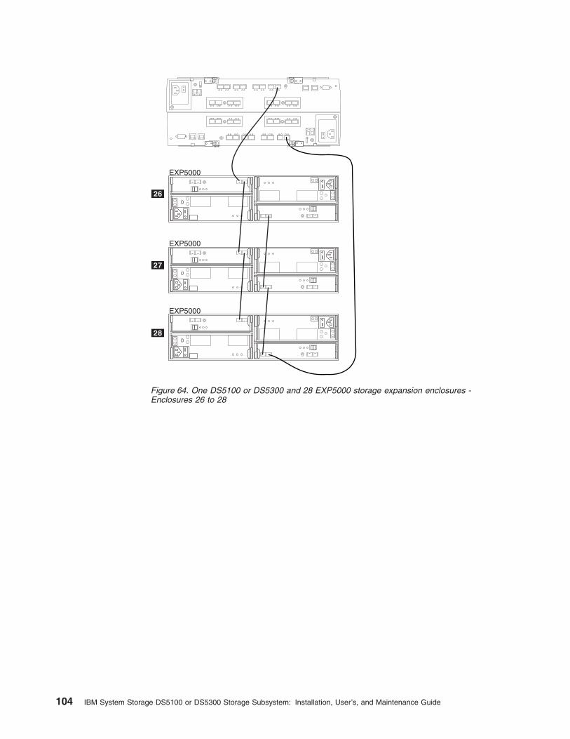
EXP5000
EXP5000
EXP5000
Figure 64. One DS5100 or DS5300 and 28 EXP5000 storage expansion enclosures -Enclosures 26 to 28
104 IBM System Storage DS5100 or DS5300 Storage Subsystem: Installation, User’s, and Maintenance Guide

Table 30. One DS5100 or DS5300 and 28 EXP5000 storage expansion enclosures - Enclosures 26 to 28
Cable
Controller A Controller BStorage ExpansionEnclosure 26
Ch1 Ch2 Ch3 Ch4 Ch5 Ch6 Ch7 Ch8ESM A(Left)
ESM B(Right)
8 7 6 5 4 3 2 1 1 2 3 4 5 6 7 8 1A 1B 1A 1B
51 X X
Cable
Storage Expansion Enclosure 26 Storage Expansion Enclosure 27
ESM A (Left) ESM B (Right) ESM A (Left) ESM B (Right)
1A 1B 1A 1B 1A 1B 1A 1B
52 X X
53 X X
Cable
Storage Expansion Enclosure 27 Storage Expansion Enclosure 28
ESM A (Left) ESM B (Right) ESM A (Left) ESM B (Right)
1A 1B 1A 1B 1A 1B 1A 1B
54 X X
55 X X
Cable
Controller A Controller BStorage ExpansionEnclosure 28
Ch1 Ch2 Ch3 Ch4 Ch5 Ch6 Ch7 Ch8ESM A(Left)
ESM B(Right)
8 7 6 5 4 3 2 1 1 2 3 4 5 6 7 8 1A 1B 1A 1B
56 X X
Chapter 3. Cabling the storage subsystem 105

One DS5100 or DS5300 and one EXP5060 storage expansionenclosure
Table 31. Cabling for DS5100 or DS5300 storage subsystem with one EXP5060 storage expansion enclosure withouttrunking
Cable
Controller A Connection Controller B ConnectionStorage Expansion EnclosureConnection
Ch1 Ch2 Ch3 Ch4 Ch5 Ch6 Ch7 Ch8 ESM A (Top) ESM B (Bottom)
8 7 6 5 4 3 2 1 1 2 3 4 5 6 7 8 1A 1B 2A 2B 1A 1B 2A 2B
Storage Expansion Enclosure 1
1 X X
2 X X
One DS5100 or DS5300 and two EXP5060 storage expansionenclosures
1A 1B A
B1A 1B
8 6 57 4 2 13
1
B
A
865 7421 3
Figure 65. Cabling for DS5100 or DS5300 storage subsystem with one EXP5060 storageexpansion enclosure without trunking
106 IBM System Storage DS5100 or DS5300 Storage Subsystem: Installation, User’s, and Maintenance Guide

Table 32. Cabling for DS5100 or DS5300 storage subsystem with two EXP5060 storage expansion enclosureswithout trunking
Cable
Controller A Connection Controller B ConnectionStorage Expansion EnclosureConnection
Ch1 Ch2 Ch3 Ch4 Ch5 Ch6 Ch7 Ch8 ESM A (Top) ESM B (Bottom)
8 7 6 5 4 3 2 1 1 2 3 4 5 6 7 8 1A 1B 2A 2B 1A 1B 2A 2B
Storage Expansion Enclosure 1
1 X X
2 X X
Storage Expansion Enclosure 2
3 X X
4 X X
One DS5100 or DS5300 and three EXP5060 storage expansionenclosures
1A 1B A
B1A 1B
1A 1B A
B1A 1B
8 6 57 4 2 13
2
B
A
865 7421 3
1
Figure 66. Cabling for DS5100 or DS5300 storage subsystem with two EXP5060 storageexpansion enclosures without trunking
Chapter 3. Cabling the storage subsystem 107

Table 33. Cabling for DS5100 or DS5300 storage subsystem with three EXP5060 storage expansion enclosureswithout trunking
Cable
Controller A Connection Controller B ConnectionStorage Expansion EnclosureConnection
Ch1 Ch2 Ch3 Ch4 Ch5 Ch6 Ch7 Ch8 ESM A (Top) ESM B (Bottom)
8 7 6 5 4 3 2 1 1 2 3 4 5 6 7 8 1A 1B 2A 2B 1A 1B 2A 2B
Storage Expansion Enclosure 1
1 X X
2 X X
Storage Expansion Enclosure 2
3 X X
4 X X
Storage Expansion Enclosure 3
5 X X
6 X X
One DS5100 or DS5300 and four EXP5060 storage expansionenclosures
B
A
8 6 57 4 2 13
865 7421 3
1A 1B A
B1A 1B
1A 1B A
B1A 1B
1A 1B A
B1A 1B
1
2
3
Figure 67. Cabling for DS5100 or DS5300 storage subsystem with three EXP5060 storageexpansion enclosures without trunking
108 IBM System Storage DS5100 or DS5300 Storage Subsystem: Installation, User’s, and Maintenance Guide
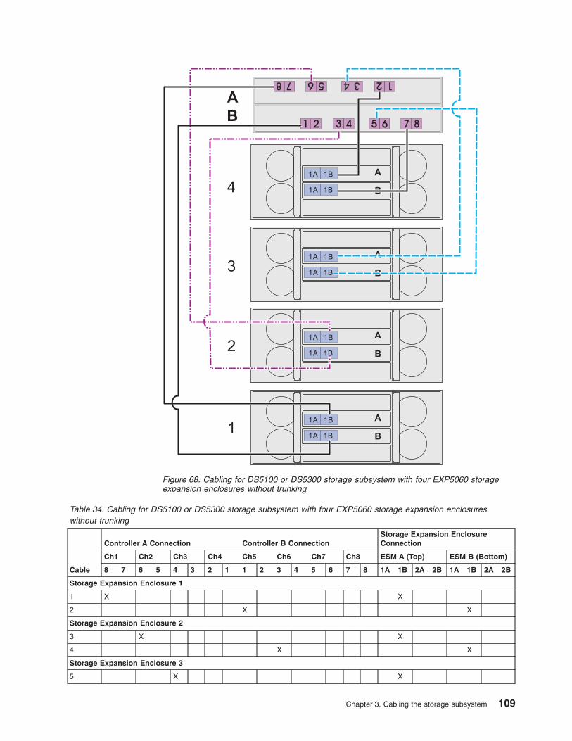
Table 34. Cabling for DS5100 or DS5300 storage subsystem with four EXP5060 storage expansion enclosureswithout trunking
Cable
Controller A Connection Controller B ConnectionStorage Expansion EnclosureConnection
Ch1 Ch2 Ch3 Ch4 Ch5 Ch6 Ch7 Ch8 ESM A (Top) ESM B (Bottom)
8 7 6 5 4 3 2 1 1 2 3 4 5 6 7 8 1A 1B 2A 2B 1A 1B 2A 2B
Storage Expansion Enclosure 1
1 X X
2 X X
Storage Expansion Enclosure 2
3 X X
4 X X
Storage Expansion Enclosure 3
5 X X
B
A
8 6 57 4 2 13
865 7421 3
1A 1B A
B1A 1B
1A 1B A
B1A 1B
1A 1B A
B1A 1B
1A 1B A
B1A 1B
1
2
3
4
Figure 68. Cabling for DS5100 or DS5300 storage subsystem with four EXP5060 storageexpansion enclosures without trunking
Chapter 3. Cabling the storage subsystem 109
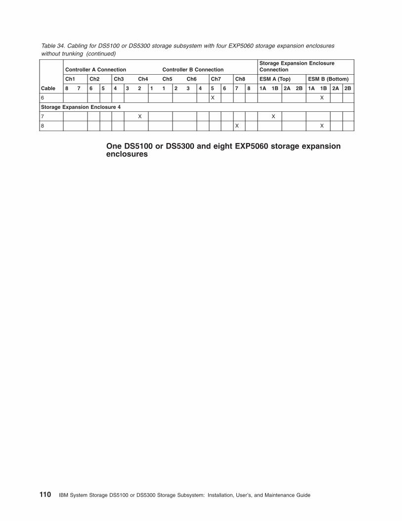
Table 34. Cabling for DS5100 or DS5300 storage subsystem with four EXP5060 storage expansion enclosureswithout trunking (continued)
Cable
Controller A Connection Controller B ConnectionStorage Expansion EnclosureConnection
Ch1 Ch2 Ch3 Ch4 Ch5 Ch6 Ch7 Ch8 ESM A (Top) ESM B (Bottom)
8 7 6 5 4 3 2 1 1 2 3 4 5 6 7 8 1A 1B 2A 2B 1A 1B 2A 2B
6 X X
Storage Expansion Enclosure 4
7 X X
8 X X
One DS5100 or DS5300 and eight EXP5060 storage expansionenclosures
110 IBM System Storage DS5100 or DS5300 Storage Subsystem: Installation, User’s, and Maintenance Guide

1A 1B A
B1A 1B
1A 1B A
B1A 1B
1A 1B A
B1A 1B
1A 1B A
B1A 1B
1
2
3
41A 1B
1A 1B
1A 1B
1A 1B
1A 1B
1A 1B
1A 1B
1A 1B
1A 1B
1A 1B
1A 1B
1A 1B
1A 1B
1A 1B
1A 1B
1A 1B
1A 1B
1A 1B
1A 1B
1A 1B
1A 1B
1A 1B
1A 1B
1A 1B
1A 1B
1A 1B
1A 1B
1A 1B
1A 1B
1A 1B
1A 1B
1A 1B
B
A
8 6 57 4 2 13
865 7421 3
1A 1B A
B1A 1B
1A 1B A
B1A 1B
1A 1B A
B1A 1B
2A 2B
2A 2B
2A 2B
2A 2B
2A 2B
2A 2B
2A 2B
2A 2B
2A 2B
2A 2B
2A 2B
2A 2B
2A 2B
2A 2B
2A 2B
2A 2B
1A 1B A
B1A 1B
5
6
7
8
Figure 69. Cabling for DS5100 or DS5300 storage subsystem with eight EXP5060 storageexpansion enclosures without trunking
Chapter 3. Cabling the storage subsystem 111
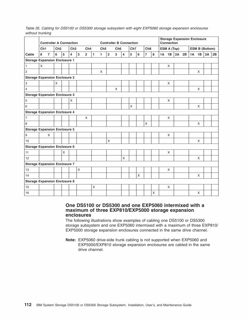
Table 35. Cabling for DS5100 or DS5300 storage subsystem with eight EXP5060 storage expansion enclosureswithout trunking
Cable
Controller A Connection Controller B ConnectionStorage Expansion EnclosureConnection
Ch1 Ch2 Ch3 Ch4 Ch5 Ch6 Ch7 Ch8 ESM A (Top) ESM B (Bottom)
8 7 6 5 4 3 2 1 1 2 3 4 5 6 7 8 1A 1B 2A 2B 1A 1B 2A 2B
Storage Expansion Enclosure 1
1 X X
2 X X
Storage Expansion Enclosure 2
3 X X
4 X X
Storage Expansion Enclosure 3
5 X X
6 X X
Storage Expansion Enclosure 4
7 X X
8 X X
Storage Expansion Enclosure 5
9 X X
10 X X
Storage Expansion Enclosure 6
11 X X
12 X X
Storage Expansion Enclosure 7
13 X X
14 X X
Storage Expansion Enclosure 8
15 X X
16 X X
One DS5100 or DS5300 and one EXP5060 intermixed with amaximum of three EXP810/EXP5000 storage expansionenclosuresThe following illustrations show examples of cabling one DS5100 or DS5300storage subsystem and one EXP5060 intermixed with a maximum of three EXP810/EXP5000 storage expansion enclosures connected in the same drive channel.
Note: EXP5060 drive-side trunk cabling is not supported when EXP5060 andEXP5000/EXP810 storage expansion enclosures are cabled in the samedrive channel.
112 IBM System Storage DS5100 or DS5300 Storage Subsystem: Installation, User’s, and Maintenance Guide

Note: The EXP5060 and the EXP5000/EXP810 storage expansion enclosures areconnected to different ports of the same drive channel in each controller.
1A 1B
1A 1B
2A 2B
2A 2B1A
EXP5060
Figure 70. Cabling for DS5100 or DS5300 storage subsystem and one EXP5060 intermixed with a maximum of threeEXP810/EXP5000 storage expansion enclosures without trunking (example 1)
Chapter 3. Cabling the storage subsystem 113

Note: The EXP5060 and the EXP5000/EXP810 storage expansion enclosures areconnected to the same port of the same drive channel in each controller.Group together the EXP5000/EXP810 storage expansion enclosures.
1A 1B
1A 1B
2A 2B
2A 2B1A
Figure 71. Cabling for DS5100 or DS5300 storage subsystem and one EXP5060 intermixed with a maximum of threeEXP810/EXP5000 storage expansion enclosures without trunking (example 2)
114 IBM System Storage DS5100 or DS5300 Storage Subsystem: Installation, User’s, and Maintenance Guide

Note: The EXP5060 and the EXP5000/EXP810 storage expansion enclosures areconnected to the same port of the same drive channel in each controller.Group together the EXP5000/EXP810 storage expansion enclosures. Cablethe configuration as illustrated if there are less than 3 EXP5000/EXP810storage expansion enclosures to be connected with the EXP5060 initiallybecause it allows the addition of EXP5000 enclosures and still be able tohave the EXP5000 enclosures cabled together.
1A 1B
1A 1B
2A 2B
2A 2B1A
Figure 72. Cabling for DS5100 or DS5300 storage subsystem and one EXP5060 intermixed with a maximum of threeEXP810/EXP5000 storage expansion enclosures without trunking (example 3)
Chapter 3. Cabling the storage subsystem 115
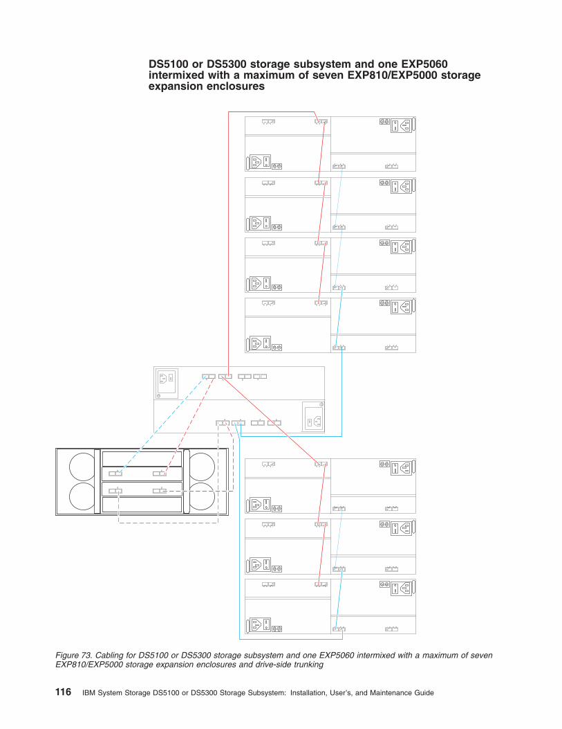
DS5100 or DS5300 storage subsystem and one EXP5060intermixed with a maximum of seven EXP810/EXP5000 storageexpansion enclosures
1A 1B
1A 1B
2A 2B
2A 2B1A
Figure 73. Cabling for DS5100 or DS5300 storage subsystem and one EXP5060 intermixed with a maximum of sevenEXP810/EXP5000 storage expansion enclosures and drive-side trunking
116 IBM System Storage DS5100 or DS5300 Storage Subsystem: Installation, User’s, and Maintenance Guide
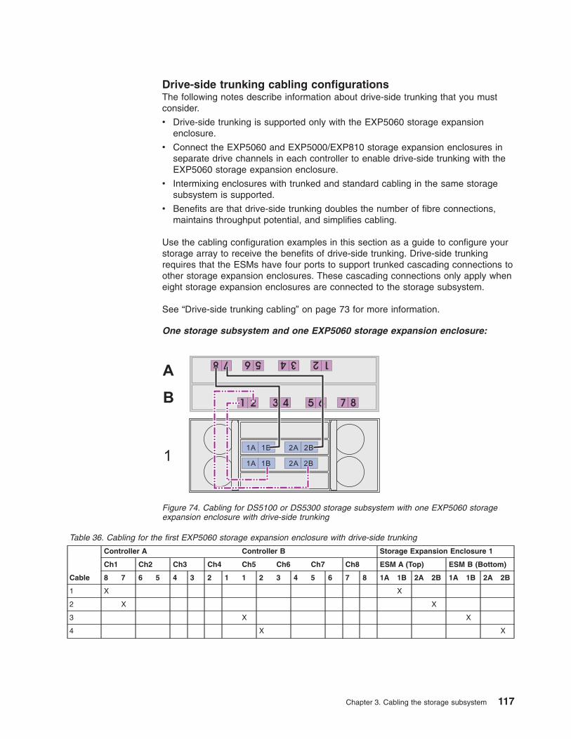
Drive-side trunking cabling configurationsThe following notes describe information about drive-side trunking that you mustconsider.
v Drive-side trunking is supported only with the EXP5060 storage expansionenclosure.
v Connect the EXP5060 and EXP5000/EXP810 storage expansion enclosures inseparate drive channels in each controller to enable drive-side trunking with theEXP5060 storage expansion enclosure.
v Intermixing enclosures with trunked and standard cabling in the same storagesubsystem is supported.
v Benefits are that drive-side trunking doubles the number of fibre connections,maintains throughput potential, and simplifies cabling.
Use the cabling configuration examples in this section as a guide to configure yourstorage array to receive the benefits of drive-side trunking. Drive-side trunkingrequires that the ESMs have four ports to support trunked cascading connections toother storage expansion enclosures. These cascading connections only apply wheneight storage expansion enclosures are connected to the storage subsystem.
See “Drive-side trunking cabling” on page 73 for more information.
One storage subsystem and one EXP5060 storage expansion enclosure:
Table 36. Cabling for the first EXP5060 storage expansion enclosure with drive-side trunking
Cable
Controller A Controller B Storage Expansion Enclosure 1
Ch1 Ch2 Ch3 Ch4 Ch5 Ch6 Ch7 Ch8 ESM A (Top) ESM B (Bottom)
8 7 6 5 4 3 2 1 1 2 3 4 5 6 7 8 1A 1B 2A 2B 1A 1B 2A 2B
1 X X
2 X X
3 X X
4 X X
8 6 57 4 2 13
865 7421 3
1A 1B
1A 1B
2A 2B
2A 2B1
B
A
Figure 74. Cabling for DS5100 or DS5300 storage subsystem with one EXP5060 storageexpansion enclosure with drive-side trunking
Chapter 3. Cabling the storage subsystem 117

One storage subsystem and two EXP5060 storage expansion enclosures:
Table 37. Cabling for the first EXP5060 storage expansion enclosure with drive-side trunking
Cable
Controller A Controller B Storage Expansion Enclosure 1
Ch1 Ch2 Ch3 Ch4 Ch5 Ch6 Ch7 Ch8 ESM A (Top) ESM B (Bottom)
8 7 6 5 4 3 2 1 1 2 3 4 5 6 7 8 1A 1B 2A 2B 1A 1B 2A 2B
1 X X
2 X X
3 X X
4 X X
Table 38. Cabling for the second EXP5060 storage expansion enclosure with drive-side trunking
Cable
Controller A Controller B Storage Expansion Enclosure 2
Ch1 Ch2 Ch3 Ch4 Ch5 Ch6 Ch7 Ch8 ESM A (Top) ESM B (Bottom)
8 7 6 5 4 3 2 1 1 2 3 4 5 6 7 8 1A 1B 2A 2B 1A 1B 2A 2B
1 X X
2 X X
3 X X
4 X X
1A 1B A
B1A 1B
2A 2B
2A 2A
8 6 57 4 2 13
865 7421 3
1A 1B A
B1A 1B
2A 2B
2A 2B1
2
B
A
Figure 75. Cabling for DS5100 or DS5300 storage subsystem with two EXP5060 storageexpansion enclosures and drive-side trunking
118 IBM System Storage DS5100 or DS5300 Storage Subsystem: Installation, User’s, and Maintenance Guide
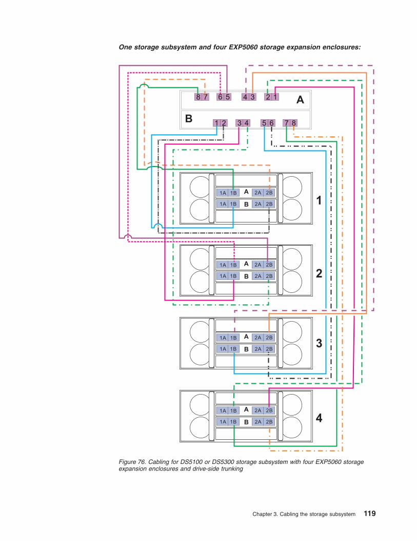
One storage subsystem and four EXP5060 storage expansion enclosures:
8 6 57 4 2 13
B
A
865 7421 3
1A 1B A
B1A 1B
2A 2B
2A 2B
1A 1B A
B1A 1B
2A 2B
2A 2B
1A 1B A
B1A 1B
2A 2B
2A 2B
1A 1B A
B1A 1B
2A 2B
2A 2B 1
2
3
4
Figure 76. Cabling for DS5100 or DS5300 storage subsystem with four EXP5060 storageexpansion enclosures and drive-side trunking
Chapter 3. Cabling the storage subsystem 119

Table 39. Cabling for the first EXP5060 storage expansion enclosure with drive-side trunking
Cable
Controller A Controller B Storage Expansion Enclosure 1
Ch1 Ch2 Ch3 Ch4 Ch5 Ch6 Ch7 Ch8 ESM A (Top) ESM B (Bottom)
8 7 6 5 4 3 2 1 1 2 3 4 5 6 7 8 1A 1B 2A 2B 1A 1B 2A 2B
1 X X
2 X X
3 X X
4 X X
Table 40. Cabling for the second EXP5060 storage expansion enclosure with drive-side trunking
Cable
Controller A Controller B Storage Expansion Enclosure 2
Ch1 Ch2 Ch3 Ch4 Ch5 Ch6 Ch7 Ch8 ESM A (Top) ESM B (Bottom)
8 7 6 5 4 3 2 1 1 2 3 4 5 6 7 8 1A 1B 2A 2B 1A 1B 2A 2B
1 X X
2 X X
3 X X
4 X X
Table 41. Cabling for the third EXP5060 storage expansion enclosure with drive-side trunking
Cable
Controller A Controller B Storage Expansion Enclosure 3
Ch1 Ch2 Ch3 Ch4 Ch5 Ch6 Ch7 Ch8 ESM A (Top)ESM B(Bottom)
8 7 6 5 4 3 2 1 1 2 3 4 5 6 7 8 1A 1B 2A 2B 1A 1B 2A 2B
1 X X
2 X X
3 X X
4 X X
Table 42. Cabling for the fourth EXP5060 storage expansion enclosure with drive-side trunking
Cable
Controller A Controller B Storage Expansion Enclosure 4
Ch1 Ch2 Ch3 Ch4 Ch5 Ch6 Ch7 Ch8 ESM A (Top) ESM B (Bottom)
8 7 6 5 4 3 2 1 1 2 3 4 5 6 7 8 1A 1B 2A 2B 1A 1B 2A 2B
1 X X
2 X X
3 X X
4 X X
120 IBM System Storage DS5100 or DS5300 Storage Subsystem: Installation, User’s, and Maintenance Guide

One storage subsystem and eight EXP5060 storage expansion enclosures:To connect eight EXP5060 storage expansion enclosures to a DS5100/DS5300storage subsystem using drive-trunking cabling, you must connect the EXP5060s infour pairs of two cascading EXP5060s each to the DS5100/DS5300 drive channelports. These connections are shown in the following illustrations:
v See Figure 77 on page 122 and Table 43 on page 123 for storage expansionenclosures 1 and 2
v See Figure 78 on page 124 and Table 44 on page 125 for storage expansionenclosures 3 and 4
v See Figure 79 on page 126 and Table 45 on page 127 for storage expansionenclosures 5 and 6
v See Figure 80 on page 128 and Table 46 on page 129 for storage expansionenclosures 7 and 8
Make the connections described in Table 43 on page 123 through Table 46 on page129 to connect the ESM A ports 1B and 2B of the first EXP5060 in a cascadingEXP5060 pair to the controller A drive channel ports and to connect ESM B ports1B and 2B of the second EXP5060 in a cascading EXP5060 pair to the controller Bdrive channel ports.
Then you must connect the EXP5060 ESMs in a cascading EXP5060 pair together.To do this, connect the ESM B ports 1A and 2A of the second EXP5060 to ESM Bports 1B and 2B of the first EXP5060 in a cascading EXP5060 pair. Then, connectESM A ports 1B and 2B of the second EXP5060 to ESM A ports 1A and 2A of thefirst EXP5060 in the cascading pair.
See also “Drive-side trunking cabling” on page 73 for more information.
Chapter 3. Cabling the storage subsystem 121

8 6 57 4 2 13
B
A
865 7421 3
1A 1B A
B1A 1B
2A 2B
2A 2B
1A 1B A
B1A 1B
2A 2B
2A 2B 1
2
Figure 77. Cabling for eight EXP5060s, storage expansion enclosures 1 and 2 with drive-sidetrunking
122 IBM System Storage DS5100 or DS5300 Storage Subsystem: Installation, User’s, and Maintenance Guide
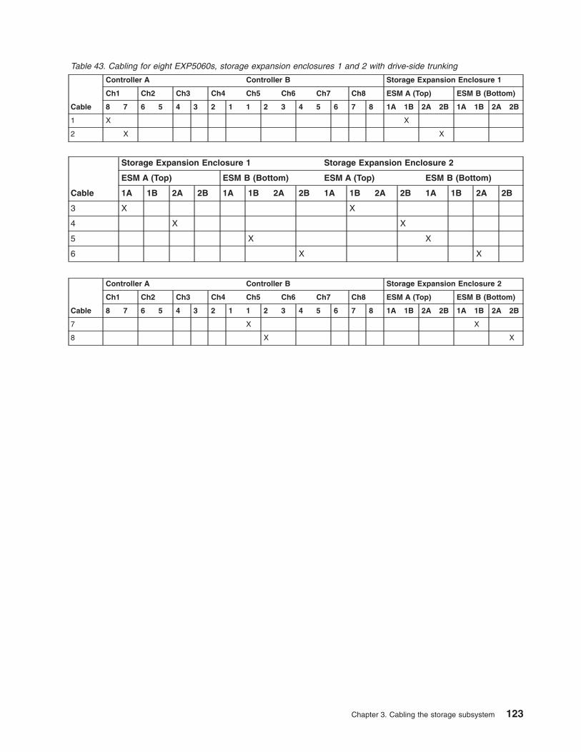
Table 43. Cabling for eight EXP5060s, storage expansion enclosures 1 and 2 with drive-side trunking
Cable
Controller A Controller B Storage Expansion Enclosure 1
Ch1 Ch2 Ch3 Ch4 Ch5 Ch6 Ch7 Ch8 ESM A (Top) ESM B (Bottom)
8 7 6 5 4 3 2 1 1 2 3 4 5 6 7 8 1A 1B 2A 2B 1A 1B 2A 2B
1 X X
2 X X
Cable
Storage Expansion Enclosure 1 Storage Expansion Enclosure 2
ESM A (Top) ESM B (Bottom) ESM A (Top) ESM B (Bottom)
1A 1B 2A 2B 1A 1B 2A 2B 1A 1B 2A 2B 1A 1B 2A 2B
3 X X
4 X X
5 X X
6 X X
Cable
Controller A Controller B Storage Expansion Enclosure 2
Ch1 Ch2 Ch3 Ch4 Ch5 Ch6 Ch7 Ch8 ESM A (Top) ESM B (Bottom)
8 7 6 5 4 3 2 1 1 2 3 4 5 6 7 8 1A 1B 2A 2B 1A 1B 2A 2B
7 X X
8 X X
Chapter 3. Cabling the storage subsystem 123

8 6 57 4 2 13
B
A
865 7421 3
1A 1B A
B1A 1B
2A 2B
2A 2B
1A 1B A
B1A 1B
2A 2B
2A 2B 3
4
Figure 78. Cabling for eight EXP5060s, storage expansion enclosures 3 and 4 with drive-sidetrunking
124 IBM System Storage DS5100 or DS5300 Storage Subsystem: Installation, User’s, and Maintenance Guide

Table 44. Cabling for eight EXP5060s, storage expansion enclosures 3 and 4 with drive-side trunking
Cable
Controller A Controller B Storage Expansion Enclosure 3
Ch1 Ch2 Ch3 Ch4 Ch5 Ch6 Ch7 Ch8 ESM A (Top) ESM B (Bottom)
8 7 6 5 4 3 2 1 1 2 3 4 5 6 7 8 1A 1B 2A 2B 1A 1B 2A 2B
1 X X
2 X X
Cable
Storage Expansion Enclosure 3 Storage Expansion Enclosure 4
ESM A (Top) ESM B (Bottom) ESM A (Top) ESM B (Bottom)
1A 1B 2A 2B 1A 1B 2A 2B 1A 1B 2A 2B 1A 1B 2A 2B
3 X X
4 X X
5 X X
6 X X
Cable
Controller A Controller B Storage Expansion Enclosure 4
Ch1 Ch2 Ch3 Ch4 Ch5 Ch6 Ch7 Ch8 ESM A (Top) ESM B (Bottom)
8 7 6 5 4 3 2 1 1 2 3 4 5 6 7 8 1A 1B 2A 2B 1A 1B 2A 2B
7 X X
8 X X
Chapter 3. Cabling the storage subsystem 125
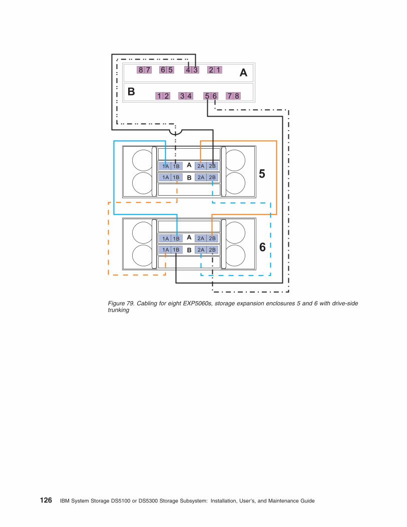
8 6 57 4 2 13
B
A
865 7421 3
1A 1B A
B1A 1B
2A 2B
2A 2B
1A 1B A
B1A 1B
2A 2B
2A 2B 5
6
Figure 79. Cabling for eight EXP5060s, storage expansion enclosures 5 and 6 with drive-sidetrunking
126 IBM System Storage DS5100 or DS5300 Storage Subsystem: Installation, User’s, and Maintenance Guide

Table 45. Cabling for eight EXP5060s, storage expansion enclosures 5 and 6 with drive-side trunking
Cable
Controller A Controller B Storage Expansion Enclosure 5
Ch1 Ch2 Ch3 Ch4 Ch5 Ch6 Ch7 Ch8 ESM A (Top) ESM B (Bottom)
8 7 6 5 4 3 2 1 1 2 3 4 5 6 7 8 1A 1B 2A 2B 1A 1B 2A 2B
1 X X
2 X X
Cable
Storage Expansion Enclosure 5 Storage Expansion Enclosure 6
ESM A (Top) ESM B (Bottom) ESM A (Top) ESM B (Bottom)
1A 1B 2A 2B 1A 1B 2A 2B 1A 1B 2A 2B 1A 1B 2A 2B
3 X X
4 X X
5 X X
6 X X
Cable
Controller A Controller B Storage Expansion Enclosure 6
Ch1 Ch2 Ch3 Ch4 Ch5 Ch6 Ch7 Ch8 ESM A (Top) ESM B (Bottom)
8 7 6 5 4 3 2 1 1 2 3 4 5 6 7 8 1A 1B 2A 2B 1A 1B 2A 2B
7 X X
8 X X
Chapter 3. Cabling the storage subsystem 127

8 6 57 4 2 13
B
A
865 7421 3
1A 1B A
B1A 1B
2A 2B
2A 2B
1A 1B A
B1A 1B
2A 2B
2A 2B 7
8
Figure 80. Cabling for eight EXP5060s, storage expansion enclosures 7 and 8 with drive-sidetrunking
128 IBM System Storage DS5100 or DS5300 Storage Subsystem: Installation, User’s, and Maintenance Guide

Table 46. Cabling for eight EXP5060s, storage expansion enclosures 7 and 8 with drive-side trunking
Cable
Controller A Controller B Storage Expansion Enclosure 7
Ch1 Ch2 Ch3 Ch4 Ch5 Ch6 Ch7 Ch8 ESM A (Top) ESM B (Bottom)
8 7 6 5 4 3 2 1 1 2 3 4 5 6 7 8 1A 1B 2A 2B 1A 1B 2A 2B
1 X X
2 X X
Cable
Storage Expansion Enclosure 7 Storage Expansion Enclosure 8
ESM A (Top) ESM B (Bottom) ESM A (Top) ESM B (Bottom)
1A 1B 2A 2B 1A 1B 2A 2B 1A 1B 2A 2B 1A 1B 2A 2B
3 X X
4 X X
5 X X
6 X X
Cable
Controller A Controller B Storage Expansion Enclosure 8
Ch1 Ch2 Ch3 Ch4 Ch5 Ch6 Ch7 Ch8 ESM A (Top) ESM B (Bottom)
8 7 6 5 4 3 2 1 1 2 3 4 5 6 7 8 1A 1B 2A 2B 1A 1B 2A 2B
7 X X
8 X X
Cabling the storage expansion enclosures to a storage subsystemComplete the following steps to cable the storage expansion enclosures to aDS5100 or DS5300:
1. Install an SFP module in the drive mini hub port on the back of the StorageSubsystem, as shown in Figure 81 on page 130.
2. Connect an LC-LC fiber-optic cable into the SFP module, as shown in Figure 82on page 130.
Chapter 3. Cabling the storage subsystem 129

Install an SFP module in the SFP port on the back of the storage expansionenclosures; then, connect the other end of the LC-LC cable into the SFP module,as shown in Figure 82.
For important information about connection rules and best practices, see “DS5100or DS5300 drive cabling best practices and rules” on page 77.
Storage expansion enclosure settingsThis section provides information about storage expansion enclosure settings. Foradditional detail, refer to the Installation, User's, and Maintenance Guide for yourstorage expansion enclosure.
ds50031
Figure 81. Installing an SFP module and LC-LC cable in a DS5100 or DS5300
Fiber-opticcable
SFPmodule
exp81012
Figure 82. Installing an SFP module and connecting an LC-LC cable to the storageexpansion enclosures
130 IBM System Storage DS5100 or DS5300 Storage Subsystem: Installation, User’s, and Maintenance Guide

DS5100 or DS5300 storage expansion enclosure ID settingsDS5100 or DS5300 storage expansion enclosures have an enclosure ID that isused to identify the DS5100 or DS5300 storage expansion enclosure on a fibrechannel loop. The enclosure ID is located on the back of the unit. The enclosure IDis set by the software. For details on enclosure ID settings, refer to the Installation,User's and Maintenance Guide for the particular storage expansion enclosure.
Note: If the enclosure ID has not been automatically set, you have to set itmanually through the software. To set the enclosure ID, see the StorageManager Online Help.
Each storage expansion enclosure in a DS5100 or DS5300 drive loop must have aunique enclosure ID. DS5100 or DS5300 controllers use a combination of theenclosure ID and the number of the physical slots that a hard drive occupies tocreate a unique fibre channel loop address, or arbitrated loop physical address(AL_PA), for each drive in a fibre channel drive loop. The enclosure ID consists oftwo digits, a tens digit (x10) and a ones digit (x1). The enclosure IDs of EXP5000sare automatically adjusted to be unique values by the EXP5000 ESM and thecontroller firmware.
Attention: When connecting storage expansion enclosures, use the tens digit(x10) enclosure ID setting to distinguish different redundant loops and use the onesdigit (x1) enclosure ID setting to distinguish storage expansion enclosures IDswithin a redundant loop. If you do not set the single digit value of the enclosure IDsto be unique among storage expansion enclosures (including the DS5100 orDS5300 with drives installed) in a redundant drive channel/loop pair, then drive looperrors might be randomly posted in the DS5100 or DS5300 subsystem Major EventLog (MEL) when you intermix different types of storage expansion enclosures in aredundant drive loop pair. For example, in a DS5100 or DS5300 configuration with16 storage expansion enclosures distributed equally behind the four controller driveports, Table 47 shows the best practice enclosure ID settings for the enclosuresconnected to the first four drive ports.
Table 47. Best practice enclosure ID settings scheme
Enclosure IDbehind the firstcontroller driveport
Enclosure IDbehind thesecondcontroller driveport
Enclosure IDbehind the thirdcontroller driveport
Enclosure IDbehind thefourth controllerdrive port
Enclosure 1 01 05 11 15
Enclosure 2 02 06 12 16
Enclosure 3 03 07 13 17
Enclosure 4 04 14
The DS5100 or DS5300 normally ships with an enclosure ID outside the range of00–77. However, if your DS5100 or DS5300 enclosure ID was set to a value withinthe range of 00–77, it may be in conflict with the enclosure ID of one of the storageexpansion enclosures that you are trying to attach to the DS5100 or DS5300. If thisis the case, the amber ID Conflict LED on the storage expansion enclosure will lightup after you power on the storage subsystem.
Give each storage expansion enclosure in a redundant drive channel pair a uniqueones digit (x1) ID. This setting will enforce hard AL_PAs (unchangeable betweenfibre channel Loop Initializations [LIPs]) for the drives and facilitate drive channel
Chapter 3. Cabling the storage subsystem 131

problem troubleshooting in the event of an error. If the ones digits are not unique,two or more devices will have the same hard AL_PA. In such a case, the DS5100or DS5300 controller will use soft AL_PAs for the devices that have identical hardAL_PAs.
The problem with soft addressing is that addresses may change between LIPs. Thispossibility increases the difficulty of troubleshooting drive channel problems, sinceone cannot easily ascertain whether the same device with a different address or adifferent device may be causing a problem.
Fibre channel loop and ID settings
When you install a hard disk drive in the storage expansion enclosure, the driveenclosure plugs into a printed circuit board called the midplane. The midplane setsthe fibre channel loop ID automatically, based on the enclosure ID switch settingand the physical location (bay) of the hard disk drive.
DS Storage Manager client host port numberingThe following notes describe the host port numbering convention used by the DSStorage Manager client to identify the host ports in controller A and controller B.The DS Manager client host port numbering is different from the port numbering onthe HIC face plate.
v Host ports are numbered from right to left in controller A, starting with 1, 2, andso on for each port. The right-most port of the HIC in slot 1 is identified as port 1by the Storage Manager.
v Host ports are numbered from left to right in controller B, starting with 1, 2, andso on for each port. The left-most port of the HIC in slot 1 is identified as port 1by the Storage Manager.
v Currently, the last port in either controller A or B is identified as either port 2, 4, 6or 8, depending on the number and type of host cards installed.
v The exception is that the iSCSI port configuration window starts counting with theiSCSI port only. In the case of mixed FC and iSCSI HICs with the iSCSI HICinstalled in slot 2, the iSCSI port configuration window identifies them as ports 1and 2, regardless of the number of Fibre Channel host ports in the HIC installedin slot 1.
Connecting hosts directly to the DS5100 or DS5300 Fibre Channel hostports
The DS5100 or DS5300 supports redundant direct connections to up to eight hosts.To ensure full protection against the loss of any one fibre channel path from thehost servers to the DS5100 or DS5300, always use redundant host connections byconnecting each host to the appropriate single-ported host channels on both RAIDcontrollers A and B.
To connect a host adapter to the DS5100 or DS5300 RAID controllers, perform thefollowing steps:
1. Install SFP modules in host ports on RAID controllers A and B.
Note: The alignment of the single-ported host channels on controller A areopposite those of controller B. Before inserting an SFP module into ahost port, verify that the SFP module is rotated correctly to match thealignment of the host port on the RAID controller. Do not force-fit.
132 IBM System Storage DS5100 or DS5300 Storage Subsystem: Installation, User’s, and Maintenance Guide
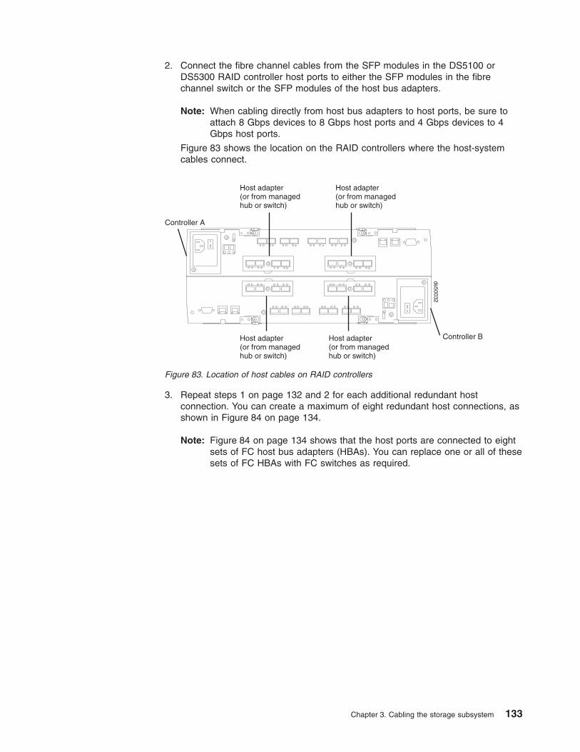
2. Connect the fibre channel cables from the SFP modules in the DS5100 orDS5300 RAID controller host ports to either the SFP modules in the fibrechannel switch or the SFP modules of the host bus adapters.
Note: When cabling directly from host bus adapters to host ports, be sure toattach 8 Gbps devices to 8 Gbps host ports and 4 Gbps devices to 4Gbps host ports.
Figure 83 shows the location on the RAID controllers where the host-systemcables connect.
3. Repeat steps 1 on page 132 and 2 for each additional redundant hostconnection. You can create a maximum of eight redundant host connections, asshown in Figure 84 on page 134.
Note: Figure 84 on page 134 shows that the host ports are connected to eightsets of FC host bus adapters (HBAs). You can replace one or all of thesesets of FC HBAs with FC switches as required.
Controller B
Controller A
Host adapter(or from managedhub or switch)
ds50032
Host adapter(or from managedhub or switch)
Host adapter(or from managedhub or switch)
Host adapter(or from managedhub or switch)
Figure 83. Location of host cables on RAID controllers
Chapter 3. Cabling the storage subsystem 133

For examples of redundant, partially redundant, and non-redundant host and drivechannel configurations, see “Fibre channel host loop configurations” on page 139.
Connecting hosts to the DS5100 or DS5300 iSCSI portsThe DS5100 or DS5300 supports redundant connections to the host with iSCSIHBAs or iSCSI software initiators. To ensure full protection against the loss of anypath from the host servers, always use redundant host connections by connectingeach host to the appropriate Ethernet switches with connections to both RAIDcontrollers A and B iSCSI host ports.
To connect a 1 Gbps iSCSI host adapter to the DS5100 or DS5300 RAIDcontrollers, complete the following steps:
1. Connect the Category 6 Ethernet cables from the RAID controller iSCSI hostports to the Ethernet switch.
2. Connect the Category 6 Ethernet cables from the iSCSI host bus adapter portsor the Ethernet ports of the server using an iSCSI software initiator to the sameEthernet switch or one that is in the same Ethernet network as the RAIDcontroller iSCSI host ports.
To connect a 10 Gbps iSCSI host adapter to the DS5100 or DS5300 RAIDcontrollers, complete the following steps:
1. Connect the OM3 fiber channel cables from the RAID controller 10Gbps iSCSIhost ports to the Ethernet switch. The Ethernet switch must have a 10 Gbpscapable Ethernet port with a 10 Gbps SFP+ module interface to connect withthe 10 Gbps iSCSI host ports.
2. Connect the iSCSI host bus adapter ports installed in the server, or the Ethernetports of the server, using an iSCSI software initiator to the same Ethernet switchor one that is in the same Ethernet network as the RAID controller 10 GbpsiSCSI host ports.
ds50057
4 3 2 1 4 3 2 1
1 3 42 1 2 3 4
Figure 84. Cabling diagram for eight redundant host connections
134 IBM System Storage DS5100 or DS5300 Storage Subsystem: Installation, User’s, and Maintenance Guide

Note: Note: Although the DS5100/DS5300 10 Gbps iSCSI host port must beoperated at 10 Gbps only, the server iSCSI HBA ports or Ethernet portscan operate at either 1 Gbps or 10 Gbps Ethernet speed.
Connecting secondary interface cablesThis section is applicable to (direct) out-of-band management configurations only. Ifyour configuration uses host-agent (in-band) management, skip this section.
Use the Ethernet interface ports on the back of the storage subsystem to connectthe controllers for direct management of the storage subsystem (see “Direct(out-of-band) management method” on page 137).
Important:
1. The serial interface ports are intended to be used by service technicians toperform diagnostic operations on the storage subsystem. Incorrect use of theserial port can result in loss of data access and, in some cases, in loss of data.Do not make connections to the serial port unless you do so under the directsupervision and guidance of IBM support personnel.
2. To minimize security risks, do not connect the DS5100 or DS5300 in a publicLAN or public subnet. Use a local private network for the DS5100 or DS5300and the management station Ethernet ports.
3. To ensure proper EMI shielding, always use quality braided and shielded serialcables.
Connect a pair of Ethernet cables from the storage-management station to theEthernet ports for controller A (located on the top) and controller B (located on thebottom) on the back of the storage subsystem. Figure 86 on page 136 shows thelocation of the ports. Only one Ethernet port connection from each controller isrequired to establish a direct (out-of-band) management connection to the DS5100or DS5300.
Ethernet switches
d5xi0
002
Figure 85. Cabling diagram for redundant iSCSI host connections
Chapter 3. Cabling the storage subsystem 135

Note: The alignment of the Ethernet and serial ports on controller A are oppositethose of controller B. Before inserting an Ethernet or serial cable, verify thatthe cable connection is rotated correctly to match the alignment of the porton the RAID controller. Do not force-fit.
Configuring the storage subsystemYou must configure the storage subsystem configuration after you install the storagesubsystem in a rack cabinet. Use the following information to configure your storagesubsystem configuration.
Storage subsystem management methodsBefore you configure the storage subsystem, determine which method of storagesubsystem management you want to use. You can manage the storage subsystemin either of two ways: host-agent (in-band) management or direct (out-of-band)management.
For more information on setting up in-band or out-of-band managementconnections, refer to the DS Storage Manager Installation and Support Guide forthe operating system of the host computer that will be used to manage the storagesubsystem.
Important: If the operating system of the host server to which the storagesubsystem logical drives are mapped is not Microsoft Windows 2000 orServer 2003, then you first have to make a direct (out-of-band)management connection to the storage subsystem to set the correcthost type. The server will then be able to recognize the storagesubsystem correctly for host-agent (in-band) management.
Host-agent (in-band) management methodThis method requires host-agent software that you install on the host server. Thehost-agent software allows the DS Storage Manager client program to manage theDS5100 or DS5300 using the same fibre channel connections between the hostserver and the storage subsystem. You must install at least one managementstation and a software agent host. The management station can be the host or a
RS-232serial portEthernet ports
Controller A
ds50033
Ethernet portsRS-232serial port
Controller B
Figure 86. Ethernet and serial port locations
136 IBM System Storage DS5100 or DS5300 Storage Subsystem: Installation, User’s, and Maintenance Guide

workstation on the Ethernet network. A management station will have the clientsoftware installed. Figure 87 shows the host-agent (in-band) management method.
Table 48 describes Figure 87.
Table 48. Description of numbered locations in the figure that shows host-agent (in-band)managed storage subsystems
Number Description
1 Two storage subsystems
2 Fibre channel I/O path
3 Host server
4 Ethernet network
5 Management station
Direct (out-of-band) management methodThis method uses Ethernet connections from a management station to eachcontroller. You must install at least one management station. The managementstation can be the host or a workstation on the Ethernet network. A managementstation will have the client software installed. Attach Ethernet cables to eachmanagement station (one pair per storage subsystem). You will connect the cablesto each storage subsystem controller later when you install the storage subsystem.Figure 88 on page 138 shows the direct (out-of-band) management method.
You can either use the default controller Ethernet IP addresses for out-of-bandconnection or change the default controller Ethernet IP addresses by usingDynamic Host Configuration Protocol (DHCP) or Storage Manager client. Refer tothe DS Storage Manager Installation, User's and Maintenance Guide for theappropriate operating system for more information on setting the managementconnections and installing the DS5100 or DS5300 management software.
Figure 87. Host-agent (in-band) managed storage subsystems
Chapter 3. Cabling the storage subsystem 137

For a listing of default IP addresses, see Ethernet ports on page 15.
Note: Do not connect the storage subsystem Ethernet ports to a public network orpublic subnet. Create a private network between the storage subsystem andthe management station.
Table 49. Description of numbered locations in the figure that shows direct (out-of-band)managed storage subsystems
Number Description
1 Two storage subsystems
2 Fibre channel I/O path
3 Host server
4 Ethernet network
5 Management station
Fibre channel and iSCSI host connectionsThe storage subsystem fibre channel connection consists of up to four hostfibre-channel loops and a redundant drive fibre-channel loop. The host fibre-channelloops provide the fibre path for host attachment. They can consist of fibre-channel
Table 49 describes Figure 88.
Figure 88. Direct (out-of-band) managed storage subsystems
138 IBM System Storage DS5100 or DS5300 Storage Subsystem: Installation, User’s, and Maintenance Guide
cables, SFPs, host bus adapters, fibre-channel switches, and RAID controllers. Theredundant drive fibre-channel loop provides the fibre path from the DS5100 orDS5300 to the hard disk drives (HDDs) in the storage expansion enclosures. Theredundant drive fibre-channel loop consists of the DS5100 or DS5300, the storageexpansion enclosures, fibre-channel cables, and SFPs.
The DS5100 or DS5300 supports redundant drive channel pair configurations. Youcan build a redundant drive channel pair by connecting one or more storageexpansion enclosures to the redundant RAID controllers. Then, use dual fiber-opticcables to connect one storage expansion enclosure to another in a daisy-chain. Formore information, see “Connecting storage expansion enclosures to the DS5100 orDS5300” on page 64.
The DS5100 or DS5300 also supports 1 Gbps or 10 Gbps iSCSI connectivity. Thehost iSCSI connections provide an iSCSI path for host attachment. The connectionscan consist of Cat6 Ethernet cables or OM3 fibre-channel cables, host bus adapterswith iSCSI initiators, or an Ethernet adapter software iSCSI initiators, Gigabit and/or10 Gigabit Ethernet switches and RAID controllers. See “iSCSI configurations” onpage 143 for more information about iSCSI configurations.
Note: A host cannot be connected to a DS5100 or DS5300 through both the FCand iSCSI host ports.
Fibre channel host loop configurationsYou must determine how the host systems will connect to the storage subsystem.You can connect up to four host systems directly to the storage subsystem, or youcan connect more than two hosts to the fibre channel storage subsystem throughswitches. The illustrations in the following sections show common host systemconfigurations.
Note: The minimum DS5100 or DS5300 configuration is eight partitions. Up to 512partition configuration upgrades are available as upgrade options. Contactyour IBM reseller or marketing representative for more information.
Redundant host and drive loopsThis section provides examples of DS5100 or DS5300 host fibre channelconfigurations.
DS5100 or DS5300 host configurations: This section provides the followingexamples of DS5100 or DS5300 host fibre channel configurations:
v Redundant host and drive fibre channel loop configurations, as shown inFigure 89 on page 140
v Single SAN fabric configuration, as shown in Figure 91 on page 141
v Dual SAN fabric configuration, with an additional DS5100 or DS5300 attached,as shown in Figure 92 on page 141
v Two clusters, as shown in Figure 93 on page 142
Notes:
1. These configurations have host and drive path failover protection and are bestpractices for high availability.
2. For the IBM recommended host to storage subsystem topology for a givencombination of installed operating system and multipath device driver, see theIBM System Storage DS Storage Manager Version 10 Installation and HostSupport Guide.
Chapter 3. Cabling the storage subsystem 139
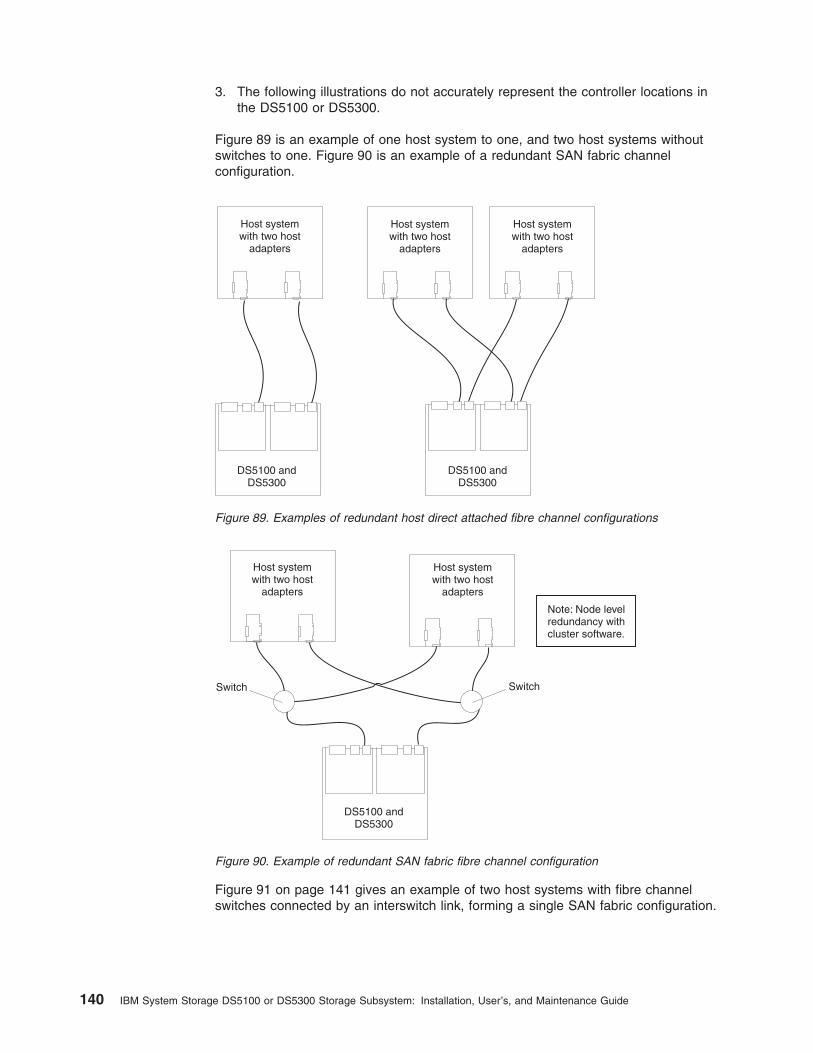
3. The following illustrations do not accurately represent the controller locations inthe DS5100 or DS5300.
Figure 89 is an example of one host system to one, and two host systems withoutswitches to one. Figure 90 is an example of a redundant SAN fabric channelconfiguration.
Figure 91 on page 141 gives an example of two host systems with fibre channelswitches connected by an interswitch link, forming a single SAN fabric configuration.
Host systemwith two host
adapters
Host systemwith two host
adapters
Host systemwith two host
adapters
DS5100 andDS5300
DS5100 andDS5300
Figure 89. Examples of redundant host direct attached fibre channel configurations
Host systemwith two host
adapters
Host systemwith two host
adapters
Switch Switch
Note: Node levelredundancy withcluster software.
DS5100 andDS5300
Figure 90. Example of redundant SAN fabric fibre channel configuration
140 IBM System Storage DS5100 or DS5300 Storage Subsystem: Installation, User’s, and Maintenance Guide

In Figure 92, the fibre channel switches are connected together.
Figure 93 on page 142 gives an example of one and four host systems configuredinto two clusters; each cluster comprised of two host systems and two fibre channelswitches
Host systemwith two host
adapters
Host systemwith two host
adapters
Switch Switch
Interswitch link
DS5100 andDS5300
Figure 91. Example of a single SAN fabric configuration
Host systemwith two host
adapters
Host systemwith two host
adapters
Switch Switch
Interswitch link
DS5100 andDS5300
DS5100 andDS5300
Figure 92. Example of two storage subsystems in a single SAN fabric environment
Chapter 3. Cabling the storage subsystem 141
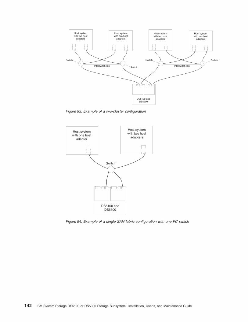
Host systemwith two host
adapters
Host systemwith two host
adapters
Switch Switch
Host systemwith two host
adapters
Host systemwith two host
adapters
Switch
SwitchInterswitch link
DS5100 andDS5300
Interswitch link
Figure 93. Example of a two-cluster configuration
Host systemwith two host
adapters
Host systemwith one host
adapter
Switch
DS5100 andDS5300
Figure 94. Example of a single SAN fabric configuration with one FC switch
142 IBM System Storage DS5100 or DS5300 Storage Subsystem: Installation, User’s, and Maintenance Guide

iSCSI configurationsThe DS5100 or DS5300 supports 1 Gbps iSCSI connectivity. You must determinehow the host systems will connect to the storage subsystem. The illustrations in thefollowing sections show common iSCSI host system configurations.
The iSCSI ports support IPv4 and IPv6 TCP/IP addresses, CHAP, and iSNS. Useeither Category 5E or Category 6 Ethernet cable types for iSCSI port connections.A Category 6 Ethernet cable provides optimal performance.
Note: The minimum DS5100 or DS5300 configuration is eight partitions. Themaximum is 512 partitions. Configuration upgrades are available as upgradeoptions. Contact your IBM reseller or marketing representative for moreinformation.
Host iSCSI configurationsThis section provides the following examples of DS5100 or DS5300 host iSCSIconfigurations:
v Single-host, multiple-port configuration, as shown in Figure 96 on page 144
v Multiple-host, multiple-port configuration, as shown in Figure 97 on page 145
v iSCSI and Fibre Channel hosts, multiple-port configuration, as shown inFigure 98 on page 145
v Example of an incorrect configuration: Single-host, iSCSI and Fibre Channel, asshown in Figure 99 on page 146
v Multiple-host, multiple-port, multiple-switch configuration, as shown in Figure 100on page 147
Attention: The DS5100 or DS5300 does not support both a 1 Gbps iSCSI HIC anda 10 Gbps iSCSI HIC in the same storage subsystem.
DS Storagesubsystem
Host systemwith two host
adapters
Host systemwith two host
adapters
Switch Switch
Figure 95. Example of a dual SAN fabric configuration with two FC switches
Chapter 3. Cabling the storage subsystem 143

Notes:
1. The DS5100 or DS5300 does not support direct connections from the hostsystems to the iSCSI ports on the storage subsystem.
2. The DS5100 or DS5300 does not support connections to both iSCSI and FibreChannel ports from the same host system.
3. The following illustrations do not accurately represent the controller locations orport locations in the DS5100 or DS5300. The illustrations are for illustrationpurposes only.
Figure 96 shows an example of a multiple port, single-host configuration. A systemthat uses multiple iSCSI ports can provide enhanced performance compared to asingle-port iSCSI connection.
Figure 97 on page 145 shows a multiple-host, multiple-port configuration. Forcluster configurations, the following illustration is an example of a multiple-host,multiple-port, and redundant path and controller configuration. You can replace thetwo gigabit Ethernet switches in the illustration with one large gigabit Ethernetswitch that has the required number of ports. Virtual local area network (VLAN) canalso be used to isolate the two iSCSI networks, instead of a single switch.
Host systemwith two iSCSI
connectors
DS5100 andDS5300
d5xi0
003
1 Gigabit or10 GigabitEthernetswitch
Figure 96. Example of a single-host, multiple-port configuration
144 IBM System Storage DS5100 or DS5300 Storage Subsystem: Installation, User’s, and Maintenance Guide

Figure 98 shows iSCSI and Fibre Channel hosts in a multiple-port configuration.
Figure 99 on page 146 shows an incorrect configuration of a single host with bothiSCSI and Fibre Channel connections.
Important: Do not cable the storage subsystem and host systems as shown inFigure 99 on page 146. A storage subsystem with the incorrect storagetopology might appear to be functional, but incorrect cabling canpotentially have unpredictable results.
Host systemwith two iSCSI
connectors
DS5100 andDS5300
Host systemwith two iSCSI
connectors
d5xi0
004
1 Gigabit or10 GigabitEthernetswitch
Ethernetswitch
Figure 97. Example of a multiple-host, multiple-port configuration
Host 1 with adual-port FibreChannel HBA
FibreChannelswitch
Controller A Controller B
FibreChannelports
iSCSIports
FibreChannelports
Host 2 with twosingle-port
iSCSI HBAs
iSCSIports
DS5100 andDS5300
d5xi0
005
1 Gigabit or10 GigabitEthernetswitch
Figure 98. Example of iSCSI and Fibre Channel hosts, multiple-port configuration
Chapter 3. Cabling the storage subsystem 145
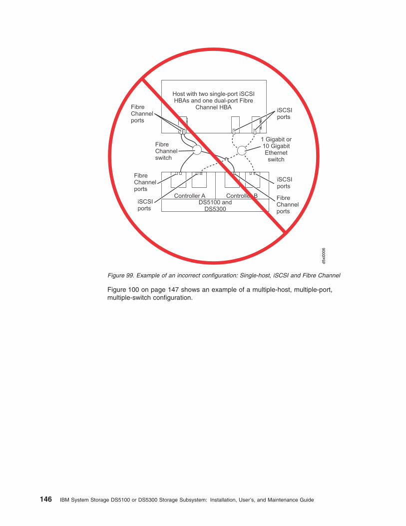
Figure 100 on page 147 shows an example of a multiple-host, multiple-port,multiple-switch configuration.
Host with two single-port iSCSIHBAs and one dual-port Fibre
Channel HBA
FibreChannelswitch
Controller A Controller B
FibreChannelports
iSCSIports
FibreChannelports
iSCSIports
FibreChannelports
iSCSIports
DS5100 andDS5300
d5xi0
006
1 Gigabit or10 GigabitEthernetswitch
Figure 99. Example of an incorrect configuration: Single-host, iSCSI and Fibre Channel
146 IBM System Storage DS5100 or DS5300 Storage Subsystem: Installation, User’s, and Maintenance Guide

Installing the storage subsystem configurationUsing the information gathered in the previous sections, install the host systemsand host adapters.
Notes:
1. See the documentation provided with your host adapters for installationrequirements and procedures.
2. Use the correct host adapter driver. For the latest supported host adapters anddrivers, go to the following Web site:
www.ibm.com/systems/support/storage/disk
Attach fiber-optic interface cables to each host adapter. You will connect the otherend of the cables to the controller later in the installation process. For moreinformation about handling fiber-optic cables, see “Handling fibre-optic cables” onpage 50.
Connecting the power cablesThis section describes the procedure for connecting power cables to the storagesubsystem.
The DS5100 or DS5300 uses two standard power cords. You can connect thepower cords to a primary power unit inside the rack cabinet, such as a properlygrounded ac distribution unit, or to an external source, such as a properly groundedelectrical outlet.
The DS5100 or DS5300 does not ship with the power cords used to connect theDS5100 or DS5300 to the electrical outlets outside the rack cabinet. Refer toAppendix E, “Power cords,” on page 271 for the list of IBM-approved power cords
Host 1 with adual-port FibreChannel HBA
Controller A Controller B
FibreChannelports
iSCSIports
FibreChannelports
Host 2 with twosingle-port
iSCSI HBAs
iSCSIports
FibreChannelswitch
DS5100 andDS5300
1 Gigabit or10 GigabitEthernetswitch
FibreChannelswitch
1 Gigabit or10 GigabitEthernetswitch
d5xi0
007
Figure 100. Example of a multiple-host, multiple-port, multiple-switch configuration
Chapter 3. Cabling the storage subsystem 147

for your region. The DS5100 or DS5300 does ship with two line jumper cords forconnecting the DS5100 or DS5300 RAID controller units to IBM-approved rackPDUs.
Use the following procedure to connect the power cables to the storage subsystem.Before you connect power cords, turn off all power switches on all modules in thecabinet. If your cabinet contains components that you do not want to power off, turnoff all power switches on the components of the storage configuration you arecurrently installing.
Statement 5:
CAUTION:The power control button on the device and the power switch on the powersupply do not turn off the electrical current supplied to the device. The devicealso might have more than one power cord. To remove all electrical currentfrom the device, ensure that all power cords are disconnected from the powersource.
1
2
1. Verify that the main circuit breakers in the cabinet are turned off.
2. If you have not already done so, turn off all power switches on each storagesubsystem and storage expansion enclosure in the cabinet. Figure 101 showsthe locations of the power switches and connectors on the storage subsystem.
3. Connect the line jumper power cords to the ac power connectors on the RAIDcontrollers.
ac powerconnector
ac powerconnector
ac powerswitch
ac powerswitch
Strain-reliefclamp
Strain-reliefclamp
ds50
039
Figure 101. AC power switch and ac power connector
148 IBM System Storage DS5100 or DS5300 Storage Subsystem: Installation, User’s, and Maintenance Guide

4. On each RAID controller, remove the nut that holds the power cablestrain-relief clamp, and then remove the strain-relief clamp.
5. Wrap the strain-relief clamp around the line jumper power cord approximately20 cm (8 in.) from the RAID controller connection end. Leave some slackbetween the clamp and the RAID controller end of the line jumper power cord.
6. Replace the strain-relief clamp, and then tighten it securely with the nut.
7. Connect the other end of the line jumper cords to two independentIBM-approved power distribution units in the rack cabinet. Connecting eachRAID controller to independent power sources maintains power redundancy. Ifapplicable, repeat this step for each additional storage subsystem and storageexpansion enclosure.
8. Connect the right and left power supplies of the attached storage expansionenclosures to the same IBM-approved power distribution units in the rackcabinet. For more information, refer to the Installation, User's, andMaintenance Guide for your DS4000® or DS5100 or DS5300 storageexpansion enclosures.
9. If you have not already done so, connect the primary power cables from therack cabinet to the external power source.
Note: To maintain power redundancy, plug the PDUs that power the storagesubsystem's right and left RAID controllers and the right and left powersupplies of the DS4000 or DS5100 or DS5300 storage expansionenclosures into two independent external power circuits through acdistribution units inside a rack cabinet or directly into externalreceptacles.
Determine the maximum surge current possible when all devices in thepower circuit are started at the same time. Based on the total number ofdevices on a power circuit, find the maximum (worst-case) specificationvalue in order to prevent the circuit from tripping. When both RAIDcontrollers are connected and the storage subsystem is powered on,each RAID controller unit will handle approximately one-half of thecurrent load. To ensure maximum protection against power loss due toRAID controller unit failure or a power circuit tripping, both RAIDcontroller units must be connected and powered on. See Table 16 onpage 32 for the DS5100 or DS5300 ac power requirements.
Do not overload the circuits that power your storage subsystem andstorage expansion enclosures. Use additional pairs of IBM-approvedpower distribution units (PDUs) if necessary.
See Figure 102 on page 150 for an example of redundant powercabling.
Chapter 3. Cabling the storage subsystem 149
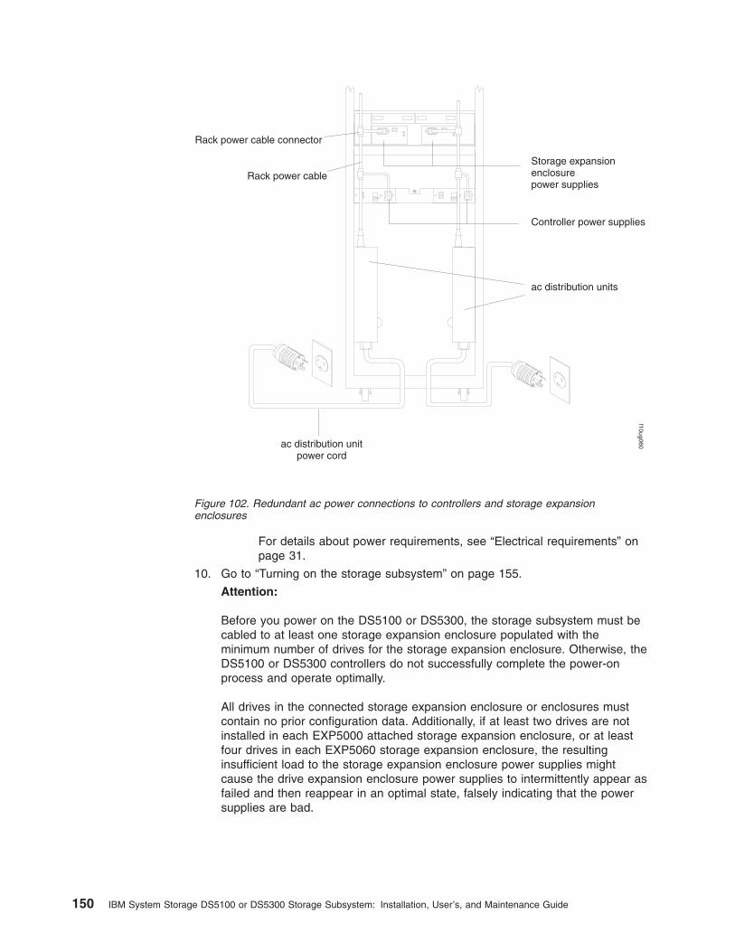
For details about power requirements, see “Electrical requirements” onpage 31.
10. Go to “Turning on the storage subsystem” on page 155.
Attention:
Before you power on the DS5100 or DS5300, the storage subsystem must becabled to at least one storage expansion enclosure populated with theminimum number of drives for the storage expansion enclosure. Otherwise, theDS5100 or DS5300 controllers do not successfully complete the power-onprocess and operate optimally.
All drives in the connected storage expansion enclosure or enclosures mustcontain no prior configuration data. Additionally, if at least two drives are notinstalled in each EXP5000 attached storage expansion enclosure, or at leastfour drives in each EXP5060 storage expansion enclosure, the resultinginsufficient load to the storage expansion enclosure power supplies mightcause the drive expansion enclosure power supplies to intermittently appear asfailed and then reappear in an optimal state, falsely indicating that the powersupplies are bad.
ac distribution unitpower cord
Controller power supplies
Storage expansionenclosurepower supplies
Rack power cable connector
Rack power cable
ac distribution units
f10ug060
Figure 102. Redundant ac power connections to controllers and storage expansionenclosures
150 IBM System Storage DS5100 or DS5300 Storage Subsystem: Installation, User’s, and Maintenance Guide

Chapter 4. Operating the storage subsystem
To ensure optimal operation of your system, always follow these best practicesguidelines:
v Ensure that your system is in an optimal state before you shut it down. Neverturn the power off if any Needs Attention LED is lit; be sure to resolve any errorconditions before you shut down the system.
v Back up the data on your storage drives periodically.
v To maintain power redundancy, plug the storage subsystem's right and left RAIDcontroller units into two independent external power circuits through acdistribution units inside a rack cabinet or directly into external receptacles.Similarly, the right and left power supplies of the DS4000 or DS5100 or DS5300storage expansion enclosures attached to the DS5100 or DS5300 should beplugged into the same two independent external power circuits as the DS5100 orDS5300. This ensures that the DS5100 or DS5300 and all its attached storageexpansion enclosures will have power if only one power circuit is available. Inaddition, having all the right or all the left power cables plug into the same powercircuit will enable the components in the storage subsystem to power onsimultaneously during an unattended restoration of power. See Figure 102 onpage 150 for an example of redundant power connections.
Note: Do not overload the circuits that power your storage subsystem andstorage expansion enclosures. Use additional pairs of power distributionunits (PDUs) if necessary. Refer to the Installation, User's, andMaintenance Guide for your storage expansion enclosures for informationon power requirements. Contact your IBM service representative foradditional information if needed.
v Before any planned system shutdown or after any system additions, removals, ormodifications (including firmware updates, logical drive creations, storagepartitioning definitions, hardware changes, and so on), save the storagesubsystem profile as explained in the DS Storage Manager guide for youroperating system. Save the profile in a location other than the logical drivescreated for the DS5100 or DS5300.
v During any maintenance or attended power-up procedure, carefully follow thepower-up sequence listed in “Turning on the storage subsystem” on page 155You should check that each component of the subsystem is powered-on in theproper order during this entire power-up procedure to ensure that the controllerwill optimally access all of your storage subsystems.
v The storage subsystem supports simultaneous power-up to the systemcomponents; however, you should always follow the power-up sequence listed in“Turning on the storage subsystem” on page 155 during any attended power-upprocedure.
v A storage system in an optimal state should recover automatically from anunexpected shutdown and unattended simultaneous restoration of power tosystem components. After power is restored, call IBM support if any of thefollowing conditions occur:
– The storage subsystem logical drives and arrays are not displayed in the DSStorage Manager graphical user interface (GUI).
– The storage subsystem logical drives and arrays do not come online.
– The storage subsystem logical drives and arrays seem to be degraded.
© Copyright IBM Corp. 2008, 2012 151
Performing the DS4000, DS5100, and DS5300 Health Check processThe DS4000, DS5100, and DS5300 Health Check process is a sequence ofsuggested actions developed by IBM to help users verify and maintain the optimalperformance of their storage configurations. The information that you collect inthese steps also helps provide IBM Service with important information needed forproblem troubleshooting during IBM Service calls.
Perform the following Health Check tasks after the initial configuration of yourstorage subsystem, and after all configuration sessions. Also, set a regular scheduleof periodic Health Check evaluations in order to keep your code current and topreserve optimal data access and performance.
1. Monitor the Recovery Guru in the Storage Manager client for any obviousstorage subsystem errors or problem conditions.
2. Gather and save the following storage subsystem event logs for review by IBMService. These event logs should be gathered periodically for regular HealthCheck monitoring regardless of the state of the Recovery Guru. (You can collectall these logs at once and zip them into a single file by clicking Advanced �Troubleshooting � Collect All Support Data in the Storage ManagerSubsystem Management window.)
v Storage subsystem management event log (MEL)
v Storage Subsystem Profile
v Read-Link Status (RLS) data
In addition, you should also collect event logs for the host servers that havemapped logical drives from the storage subsystem.
Attention: Save these event log files to a server disk that will remainaccessible in the event of a storage configuration failure. Do not save theseevent log files only to a LUN in the storage subsystem.
3. Use the Storage Subsystem Profile to verify that the following firmware levelsare at the latest versions supported for the storage subsystem:
v Controller firmware
v ESM firmware
v Drive firmware
If you discover your firmware is not up-to-date, upgrade the firmware andsoftware to the latest level appropriate to your storage configuration. See “Webpages” on page 153 for information about where to find the latest firmware andsoftware.
Attention: You must resolve Recovery Guru errors or problems beforeupgrading firmware.
Save the storage subsystem profile before performing any controller or ESMfirmware upgrades. Save the storage subsystem profile and all *.cfg files to aserver disk that will remain accessible in the event of a storage configurationfailure.
Note: When you upgrade firmware, you must upgrade all client packagecomponents to the same release level. For example, if you are upgradingyour controller firmware from version 5.x to version 6.x, you must alsoupgrade your Storage Manager client to version 9.x or higher. If yourhost system uses RDAC, upgrading controller firmware from version 5.xto version 6.x might also require host software updates, such as RDACupdates and HBA driver updates. Refer to the IBM DS4000, DS5100,and DS5300 Web site for detailed instructions.
152 IBM System Storage DS5100 or DS5300 Storage Subsystem: Installation, User’s, and Maintenance Guide

4. Use the Storage Subsystem Profile to verify that the following functions areenabled:
v For all DS4000, DS5100, and DS5300 models, Media Scan should beenabled both at the controller level and at the LUN level.
v For all DS4000, DS5100, and DS5300 models, the read/write cache shouldbe enabled. In addition, use the Storage Subsystem Profile to verify thatcache is matched between the controllers.
Web pagesIBM maintains pages on the World Wide Web where you can get the latesttechnical information and download device drivers and updates.
For DS4000, DS5100, and DS5300 information, go to the following Web site:
www.ibm.com/servers/storage/support/disk/
For the latest information about operating system and HBA support, clusteringsupport, SAN fabric support, and Storage Manager feature support, see theDS4000, DS5100, and DS5300 Interoperability Matrix at the following Web site:
www.ibm.com/servers/storage/disk/ds4000/interop-matrix.html
Hardware responsibilitiesIn addition to the Health Check steps described above, regular hardware inspectionand maintenance helps to support the optimal performance of your storageconfiguration. You should periodically inspect the Fibre Channel components of yourstorage configuration.
IBM suggests you follow these guidelines:
v Maintain an up-to-date storage subsystem profile for your storage configuration.Save the profile to a server disk that will remain accessible in case of a storageconfiguration failure. Do not save the profile only to a LUN in the storagesubsystem.
v Develop a Change Management plan. The plan should include schedules forupdating subsystem firmware and server host software.
Note: Some updates might require storage subsystem downtime.
v Use IBM-approved Fibre Channel cables for all situations. Note in yourconfiguration documentation whether any cables are not IBM-approved.
v Create and maintain a cabling diagram of the current SAN configuration. Keepthis diagram updated as you make configuration changes, and keep the cablingdiagram available for review.
v Create and maintain a list of other components that are being used within thecabling diagram (such as the host system, Fibre Channel switches, and otherSAN attachments).
v Ensure that all ESMs are properly seated.
v Ensure that all drives are properly seated.
v Ensure that all SFP modules are properly seated.
v Confirm Fibre Channel cable loop size. (IBM specifications call for at least 3-inchcable loops, but it is best practice to use 6-inch cable loops or longer.)
v Ensure proper Fibre Channel cable management.
Chapter 4. Operating the storage subsystem 153
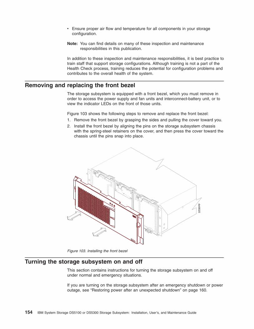
v Ensure proper air flow and temperature for all components in your storageconfiguration.
Note: You can find details on many of these inspection and maintenanceresponsibilities in this publication.
In addition to these inspection and maintenance responsibilities, it is best practice totrain staff that support storage configurations. Although training is not a part of theHealth Check process, training reduces the potential for configuration problems andcontributes to the overall health of the system.
Removing and replacing the front bezelThe storage subsystem is equipped with a front bezel, which you must remove inorder to access the power supply and fan units and interconnect-battery unit, or toview the indicator LEDs on the front of those units.
Figure 103 shows the following steps to remove and replace the front bezel:
1. Remove the front bezel by grasping the sides and pulling the cover toward you.
2. Install the front bezel by aligning the pins on the storage subsystem chassiswith the spring-steel retainers on the cover, and then press the cover toward thechassis until the pins snap into place.
Turning the storage subsystem on and offThis section contains instructions for turning the storage subsystem on and offunder normal and emergency situations.
If you are turning on the storage subsystem after an emergency shutdown or poweroutage, see “Restoring power after an unexpected shutdown” on page 160.
ds48025
Figure 103. Installing the front bezel
154 IBM System Storage DS5100 or DS5300 Storage Subsystem: Installation, User’s, and Maintenance Guide
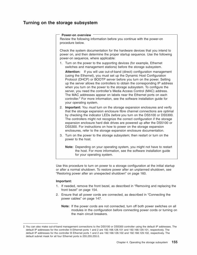
Turning on the storage subsystem
Power-on overviewReview the following information before you continue with the power-onprocedure below.
Check the system documentation for the hardware devices that you intend topower on, and then determine the proper startup sequence. Use the followingpower-on sequence, where applicable:
1. Turn on the power to the supporting devices (for example, Ethernetswitches and management stations) before the storage subsystem.
Attention: If you will use out-of-band (direct) configuration management(using the Ethernet), you must set up the Dynamic Host ConfigurationProtocol (DHCP) or BOOTP server before you turn on the power. Settingup the server allows the controllers to obtain the corresponding IP addresswhen you turn on the power to the storage subsystem. To configure theserver, you need the controller’s Media Access Control (MAC) address.The MAC addresses appear on labels near the Ethernet ports on eachcontroller.2 For more information, see the software installation guide foryour operating system.
2. Important: You must turn on the storage expansion enclosures and verifythat the storage expansion enclosure fibre channel connections are optimalby checking the indicator LEDs before you turn on the DS5100 or DS5300.The controllers might not recognize the correct configuration if the storageexpansion enclosure hard disk drives are powered up after the DS5100 orDS5300. For instructions on how to power on the storage expansionenclosures, refer to the storage expansion enclosure documentation.
3. Turn on the power to the storage subsystem; then restart or turn on thepower to the host.
Note: Depending on your operating system, you might not have to restartthe host. For more information, see the software installation guidefor your operating system.
Use this procedure to turn on power to a storage configuration at the initial startupor after a normal shutdown. To restore power after an unplanned shutdown, see“Restoring power after an unexpected shutdown” on page 160.
Important:
1. If needed, remove the front bezel, as described in “Removing and replacing thefront bezel” on page 154.
2. Ensure that all power cords are connected, as described in “Connecting thepower cables” on page 147.
Note: If the power cords are not connected, turn off both power switches on allmodules in the configuration before connecting power cords or turning onthe main circuit breakers.
2. You can also make out-of-band management connections to the DS5100 or DS5300 controller using the default IP addresses. Thedefault IP addresses for the controller A Ethernet ports 1 and 2 are 192.168.128.101 and 192.168.129.101, respectively. Thedefault IP addresses for the controller B Ethernet ports 1 and 2 are 192.168.128.102 and 192.168.129.102, respectively. Thedefault subnet mask for all four Ethernet ports is 255.255.255.0.
Chapter 4. Operating the storage subsystem 155
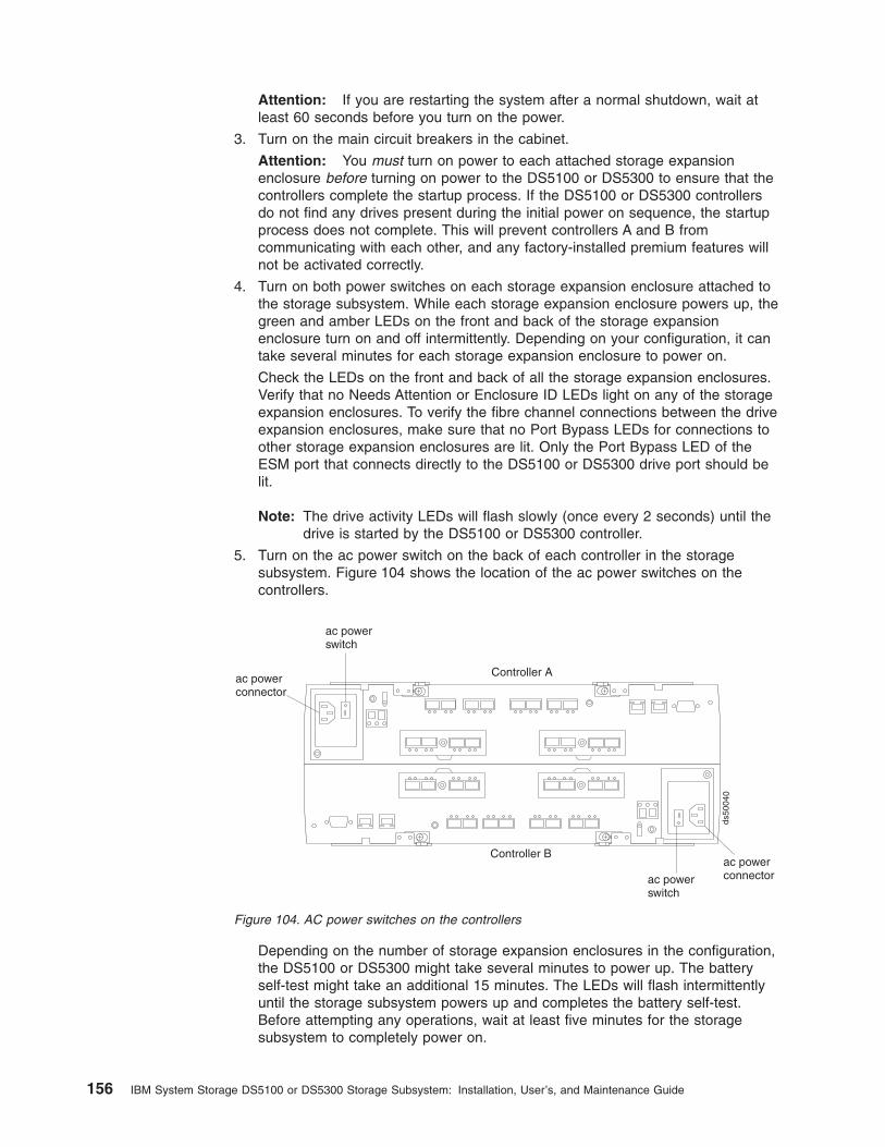
Attention: If you are restarting the system after a normal shutdown, wait atleast 60 seconds before you turn on the power.
3. Turn on the main circuit breakers in the cabinet.
Attention: You must turn on power to each attached storage expansionenclosure before turning on power to the DS5100 or DS5300 to ensure that thecontrollers complete the startup process. If the DS5100 or DS5300 controllersdo not find any drives present during the initial power on sequence, the startupprocess does not complete. This will prevent controllers A and B fromcommunicating with each other, and any factory-installed premium features willnot be activated correctly.
4. Turn on both power switches on each storage expansion enclosure attached tothe storage subsystem. While each storage expansion enclosure powers up, thegreen and amber LEDs on the front and back of the storage expansionenclosure turn on and off intermittently. Depending on your configuration, it cantake several minutes for each storage expansion enclosure to power on.
Check the LEDs on the front and back of all the storage expansion enclosures.Verify that no Needs Attention or Enclosure ID LEDs light on any of the storageexpansion enclosures. To verify the fibre channel connections between the driveexpansion enclosures, make sure that no Port Bypass LEDs for connections toother storage expansion enclosures are lit. Only the Port Bypass LED of theESM port that connects directly to the DS5100 or DS5300 drive port should belit.
Note: The drive activity LEDs will flash slowly (once every 2 seconds) until thedrive is started by the DS5100 or DS5300 controller.
5. Turn on the ac power switch on the back of each controller in the storagesubsystem. Figure 104 shows the location of the ac power switches on thecontrollers.
Depending on the number of storage expansion enclosures in the configuration,the DS5100 or DS5300 might take several minutes to power up. The batteryself-test might take an additional 15 minutes. The LEDs will flash intermittentlyuntil the storage subsystem powers up and completes the battery self-test.Before attempting any operations, wait at least five minutes for the storagesubsystem to completely power on.
ac powerconnector
ac powerconnector
ac powerswitch
ac powerswitch
ds50
040
Controller A
Controller B
Figure 104. AC power switches on the controllers
156 IBM System Storage DS5100 or DS5300 Storage Subsystem: Installation, User’s, and Maintenance Guide

The DS5100 or DS5300 spins up all the drives in the storage expansionenclosures during the startup process.
6. Determine the status of all storage subsystems and components in theconfiguration by completing the following steps:
a. Check all LEDs on each component in the storage expansion enclosures.Ensure that all the LEDs show normal status. For more information on LEDstatus for storage expansion enclosures, see the Installation, User's, andMaintenance Guide for your storage expansion enclosure.
b. Check all LEDs on each component in the storage subsystem. Ensure thatall the LEDs show normal status. For information about LED status, see“Checking the LEDs” on page 167.
c. Open the DS Storage Manager Subsystem Management window, anddisplay the Physical View for the configuration.
The status for each component is either Optimal or Needs Attention.
d. Review the status of the configuration components shown in the SubsystemManagement window by selecting the appropriate component button foreach storage subsystem.
7. Are the LEDs indicating normal operation, and is the status Optimal on all theconfiguration components?
v Yes – End of procedure. Replace front bezel, as described in “Removing andreplacing the front bezel” on page 154.
v No – Go to step 8.
8. Diagnose and correct the fault by completing the following steps:
a. Run the DS Storage Manager Recovery Guru by selecting the RecoveryGuru toolbar button in the Subsystem Management window.
b. Complete the recovery procedure.
If the Recovery Guru directs you to replace a failed component, use theindividual LEDs on the storage subsystem to locate the failed component.(For procedures to replace a failed component, see Chapter 5, “Replacingcomponents,” on page 189.)
c. When the recovery procedure is completed, select Recheck in the RecoveryGuru. This action reruns the Recovery Guru to ensure that the problem hasbeen fixed.
d. If the problem has not been fixed, contact your IBM service representative.
Turning off the storage subsystem
Attention: Except in an emergency, never turn off the power if any storagesubsystem's Needs Attention LEDs are on. Correct the fault before you turn off thepower. Use the DS Storage Manager client and the Needs Attention LEDs to checkthe overall status of the storage subsystem and its components. All LEDs should begreen on the front of the storage subsystem. If they are not, use the DS StorageManager client to diagnose the problem (see “Monitoring status through software”on page 164). This ensures that the storage subsystem will power on correctly later.
The storage subsystem is designed to run continuously, 24 hours a day. After youturn on the storage subsystem, do not turn it off except in the following situations:
v Instructions in a hardware or software procedure require you to turn off thepower.
v A service technician tells you to turn off the power.
Chapter 4. Operating the storage subsystem 157

v A planned power outage or emergency situation occurs (see “Performing anemergency shutdown” on page 160).
Statement 5:
CAUTION:The power control button on the device and the power supply do not turn offthe electrical current supplied to the device. The device also might have morethan one power cord. To remove all electrical current from the device, ensurethat all power cords are disconnected from the power source.
1
2
Attention: Turning the power off and on without waiting for the storage expansionenclosure disk drives to spin down, can damage the drives and might cause dataloss. Wait at least 70 seconds after turning the power off before turning it on, again.
Power-off overviewReview the following information before you continue with the power-offprocedure below.
Turn off the power to each device based on the following shutdown sequence:
1. Turn off power to the host before the storage subsystem. If the host muststay powered on to support an existing network, see the operating systemdocumentation for information about disconnecting the storage subsystemlogical drives from the host before the storage subsystem is powered off.
2. Turn off power to the storage subsystem before you turn off power to thestorage expansion enclosures. Turn off both power supply switches on theback of the storage subsystem.
3. Turn off power to other supporting devices (for example, managementstations, fibre-channel switches, or Ethernet switches).
Note: You do not need to perform this step if you are servicing only thestorage subsystem.
Use the following procedure to turn off power to one or more storage subsystemsfor a planned shutdown. To turn off power for an unplanned shutdown, see“Performing an emergency shutdown” on page 160.
Before proceeding, use the DS Storage Manager client to determine the status ofthe system components and special instructions. The operating system softwaremight require you to perform other procedures before you turn off the power.
1. Stop all I/O activity to the storage subsystems.
158 IBM System Storage DS5100 or DS5300 Storage Subsystem: Installation, User’s, and Maintenance Guide

2. Determine the status of all storage subsystems and components in theconfiguration by completing the following steps.
a. Check all LEDs on each component in the storage expansion enclosures.Ensure that all the LEDs show normal status.
b. Check all LEDs on each component in the storage subsystem. Ensure thatall the LEDs show normal status. For information about LED status, see“Checking the LEDs” on page 167.
c. Open the Subsystem Management window for the configuration and displaythe Physical View for the configuration.
d. Review the status of the configuration components shown in the SubsystemManagement window by selecting the appropriate component button foreach storage subsystem.
The status for each component is either Optimal or Needs Attention.
3. Are the LEDs indicating normal operation, and is the status Optimal on all theconfiguration components?
v Yes – Go to step 5.
v No – Go to step 4.
4. To diagnose and correct the fault, complete the following steps:
a. Run the Recovery Guru by selecting the Recovery Guru toolbar button inthe Subsystem Management window.
b. Complete the recovery procedure.
If the Recovery Guru directs you to replace a failed component, use theindividual LEDs on the storage subsystem to locate the failed component.
c. When the recovery procedure is completed, select Recheck in the RecoveryGuru. This action reruns the Recovery Guru to ensure that the problem hasbeen fixed.
d. If the problem has not been fixed, contact your IBM service representative.Do not turn off power until all problems are corrected.
5. Check the back of the storage subsystem, and verify that the Cache Active LEDis off.
If the Cache Active LED is on steady, the cache contains data. Wait for the datato clear from cache memory before turning off the power.
6. Check the LEDs on the storage expansion enclosures to verify that all DriveActive LEDs are on steady (not flashing).
If one or more LEDs are flashing, data is being written to or from the drives.Wait for all Active LEDs to stop flashing.
7. Turn off the ac power switch on the back of each controller in the storagesubsystem. (Figure 101 on page 148 shows the location of the ac power switchon a controller.)
Note: Until the power switch on each controller is turned off, power still remainsturned on for the both controllers; therefore, the seven-segment displayon each controller stays on until the power switch on each controller isturned off.
8. Turn off both power switches on the back of each storage expansion enclosurein the configuration.
Note: After you power off the storage subsystem, the controller remainspowered on for three to four minutes to flush any data in cache memoryto the flash memory modules.
Chapter 4. Operating the storage subsystem 159

9. After you perform the necessary maintenance procedures, turn on the powerusing the procedure in “Turning on the storage subsystem” on page 155.
Restoring power after an unexpected shutdownThe storage subsystem might shut down unexpectedly under any of the followingconditions:
Attention: There might be a loss of access to data in each of the following cases.
v The internal temperature of the storage subsystem exceeds the maximumoperating temperature (an over-temperature condition).
If both power supply and fan units fail or are unable to maintain an internaltemperature below 70° C (158° F), one or both of the power supplies in thestorage subsystem will shut down. If both power supply and fan units shut down,the unit is inoperable.
The DS Storage Manager client warns you if the temperature of the unit is risingbefore it has risen sufficiently to shut down the power supplies. The first warningcomes when the storage subsystem internal temperature exceeds 45° C (113°F). The storage subsystem shuts down if the temperature rises to 70° C (158° F).
v In the DS5100 or DS5300, the right power supply and fan unit is linked tocontroller A, and the left power supply and fan unit is linked to controller B. If onepower supply and fan unit has shut down and the controller that is linked to theother power supply and fan unit is removed, the DS5100 or DS5300 isinoperable. To increase protection against power loss, always make sure thatboth power supply and fan units are plugged in and are operational.
v There is a general power failure or a loss of power to the unit.
v You are forced to shut down the storage subsystem without performing thenormal shutdown procedures (listed in “Turning off the storage subsystem” onpage 157) because of an emergency situation.
Attention: To avoid damage to the hardware, take special care when you restartthe system after an unexpected shutdown.
Note: Unattended restoration of power is supported; however, if power restorationis attended, you should follow the best practices guidelines and the powerrestoration sequence in “Turning on the storage subsystem” on page 155.
Performing an emergency shutdownEmergency situations might include fire, flood, extreme weather conditions, or otherhazardous circumstances. If a power outage or emergency situation occurs, alwaysturn off all power switches on all computing equipment. This will help safeguardyour equipment from potential damage due to electrical surges when power isrestored. If the storage subsystem loses power unexpectedly, it might be due to ahardware failure in the power system or midplane (see Chapter 6, “Hardwaremaintenance,” on page 231).
Use the following procedure to shut down the storage subsystem during anemergency:
1. If you have time, stop all I/O activity to the storage subsystem by shutting downthe host or disconnecting the storage subsystem logical drives through the host.
2. Check the LEDs (front and back). Make note of any Needs Attention LEDs thatare on so you can correct the problem when you turn on the power again.
160 IBM System Storage DS5100 or DS5300 Storage Subsystem: Installation, User’s, and Maintenance Guide

3. Turn off all power-supply switches; then unplug the power cords from thestorage subsystem.
Restoring power after an emergency shutdownUse the following procedure to restore power to the storage subsystem in aconfiguration after an unplanned shutdown.
Risk of severe electrical shock – Never turn on the power to any equipment ifthere is evidence of fire, water, or structural damage. Doing so might cause severeelectrical shock.
1. Visually check the equipment for damage. Is there evidence of damage to anyof the storage subsystem components, cables, or equipment attached to thestorage subsystem?
v Yes – Do not continue with this procedure. Contact your IBM servicerepresentative for assistance. Depending on the current service agreements,you might need to return the equipment to the factory or local service centerfor repair.
v No – Go to step 2.
Potential data loss – Before resetting circuit breakers in the cabinet, ensurethat the storage subsystem and storage expansion enclosures power switchesare turned off. Resetting circuit breakers after an emergency situation while thestorage subsystem and storage expansion enclosure power switches areturned on can cause potential data loss because the configuration componentsmight not be powered on in the correct sequence. See “Turning on the storagesubsystem” on page 155 for details about the correct power-on sequence.
2. Do whatever is necessary to cool the unit (replace the fans, use external fansto cool the room, and so on).
3. Verify the main circuit breakers in the cabinet are turned off.
4. Verify that the ac power switch on each DS5100 or DS5300 is turned off.(Figure 101 on page 148 shows the location of the ac power switch on eachcontroller.)
5. Verify that both power switches on all storage expansion enclosures in theconfiguration are turned off.
6. Turn on the main circuit breakers in the cabinet.
7. Turn on both power switches on the back of each storage expansionenclosure.
Attention: You must turn on power to each attached storage expansionenclosure before turning on power to the storage subsystem to ensure that thecontrollers acknowledge each storage expansion enclosure.
8. Verify that no ESM port bypass LEDs are lit on any storage expansionenclosures.
If any ESM port bypass LEDs are lit, reseat the ESMs and check the ESM portbypass LEDs again.
If the ESM port bypass LEDs remain lit, then reseat the SFP modules and thefibre channel cables at both ends of the connections.
If the problem is not resolved, use the fibre channel wrap-plug and coupler toattempt to isolate the problem to the ESM port, SFP, or fibre channel cable.See the IBM System Storage Problem Determination Guide for information onperforming wrap plug tests.
9. Turn on the ac power switch on the back of each controller in the storagesubsystem. Figure 101 on page 148 shows the location of the ac power switch
Chapter 4. Operating the storage subsystem 161
on the controller. The storage subsystem might take several minutes to poweron, depending on the number of attached storage expansion enclosures. Thebattery self-test might take an additional 15 minutes. The LEDs will flashintermittently until the storage subsystem powers up and completes the batteryself-test.
10. Determine the status of all storage subsystems and their components in theconfiguration, by completing the following steps:
a. Check all LEDs on each component in the storage expansion enclosures.Ensure that all the LEDs show normal status.
b. Check all LEDs on each component in the DS5100 or DS5300. Ensure thatall the LEDs show normal status. For information about LED status, see“Checking the LEDs” on page 167.
c. Open the Subsystem Management window, and display the Physical Viewfor the configuration.
d. Review the status of the configuration components shown in theSubsystem Management window by selecting the appropriate componentbutton for each storage subsystem. The status for each component will beeither Optimal or Needs Attention.
11. Are the LEDs indicating normal operation, and is the status Optimal on all theconfiguration components?
v Yes – End of procedure.
v No – Go to step 12.
12. Diagnose and correct the fault by completing the following steps:
a. Run the Recovery Guru by selecting the Recovery Guru toolbar button inthe Subsystem Management window.
b. Complete the recovery procedure. If the Recovery Guru directs you toreplace a failed component, use the individual LEDs on the storagesubsystem to locate the specific failed component. (For more ontroubleshooting the storage subsystem, see “Troubleshooting the storagesubsystem” on page 166.)
c. When the recovery procedure is completed, select Recheck in theRecovery Guru. This action reruns the Recovery Guru to ensure that theproblem has been fixed.
d. If the problem has not been fixed, contact your IBM service representative.
Responding to the audible alarm
Attention: The DS5100 or DS5300 ships with the audible alarm option disabled.You can enable the audible alarm with the DS Storage Manager client. If theaudible alarm is enabled, you must remove the DS5100 or DS5300 bezel in orderto mute the alarm.
The alarm provides an audible warning of potentially serious problems with thestorage subsystem. The storage subsystem is shipped with the alarm disabled. Youcan enable or disable the Audible Alarm feature using the DS Storage ManagerSubsystem Management window graphical user interface (GUI). Any change youmake takes effect after approximately five minutes. If you enable the alarm, theDS5100 or DS5300 alarm will sound upon the next detection of a storagesubsystem failure.
Note: The alarm will not sound when it is enabled if it detects a subsystem failurethat has been detected by the controllers prior to the enabling of the alarm.
162 IBM System Storage DS5100 or DS5300 Storage Subsystem: Installation, User’s, and Maintenance Guide

The GUI indicates alarm status for the storage subsystem as follows:
v Alarm control (enabled/disabled)
v Alarm state (inactive/sounding/muted)
The GUI provides the following alarm controls for the storage subsystem:
v Enable/disable alarm. (Error status is displayed if an attempt is made to enablean alarm that is not present.)
v Mute alarm.
The alarm sounds and the Overall Configuration Needs Attention turns on when oneof the following conditions occur:
v Hardware malfunction in a storage subsystem – This includes an overheatingcondition or a component failures (controllers, power supplies, or fans).
v Transmission failures – This includes I/O transmission problems with the SFPmodules or cables.
When a subsystem failure is detected after the alarm has been enabled, the alarmsounds until one of the following occurs:
v The alarm is muted using the DS Storage Manager Subsystem Managementwindow GUI.
v The alarm is muted using the Mute button on the interconnect-battery unit.
v The problem that is indicated by the lit Overall Configuration Needs AttentionLED is resolved.
If the alarm sounds, check the storage subsystem for faults. For troubleshootingprocedures, see “Troubleshooting the storage subsystem” on page 166.
Installing the DS Storage Manager clientFor instructions to install the DS Storage Manager software, see the IBM SystemStorage DS Storage Manager Version 10 Installation and Host Support Guide forthe appropriate operating system. Use that document and the online help toconfigure the logical drives, partitions, and so on for the RAID controllers. Use youroperating system documentation to make the new logical drives accessible to theoperating system. Do not proceed with the configuration setup until you havecompleted the DS Storage Manager installation.
Assemble any additional items in preparation for software installation. These itemsmight include the following:
v HBA drivers.
v Controller firmware version listed at the IBM DS5100 or DS5300 System StorageSupport Web site:
www.ibm.com/systems/support/storage/disk
v IP addresses for RAID controllers (for out-of-band management only).
v Additional documentation for switches and HBAs, if needed.
v DS Storage Manager Support DVD, which includes the storage subsystemcontroller firmware.
v The DS5100 or DS5300 controller firmware should be updated to the correctversion. See “Software and hardware compatibility and upgrades” on page 25 forversion information. The latest level of DS5100 or DS5300 controller firmware isavailable for download from the IBM support Web site for DS5100 or DS5300storage products.
Chapter 4. Operating the storage subsystem 163

v Appropriate host kit for your operating system.
Depending on the model, your DS5100 or DS5300 ships with either the MicrosoftWindows host software attachment kit or with your choice of host software kits(Windows, AIX, Linux, Mac OS, SUN Solaris, HP-UX, Linux on POWER, orVMware). The host software kit grants you permission to attach host serversusing the appropriate operating system to the DS5100 or DS5300. The kitincludes a DS Storage Manager Version 10 Support DVD that has theappropriate IBM DS Storage Manager host software. The DVD also containsincludes appropriate controller firmware version.
For the latest controller firmware, check the IBM support Web site for DS5100 orDS5300 storage products.
www.ibm.com/systems/support/storage/disk
Before any planned system shutdown or after any system additions, removals, ormodifications (including firmware updates, logical drive creations, storagepartitioning definitions, hardware changes, and so on), save the storage subsystemprofile as explained in the DS Storage Manager guide for your operating system.Save the profile in a location other than the logical drives created for the DS5100 orDS5300.
Always refer to the README that is included with the DS5100 or DS5300 firmwarepackage (whether the firmware is accessed by the Web or DVD) for any specialrequirements or restrictions that apply to that particular firmware version. See“Finding Storage Manager software, controller firmware, and README files” onpage xxviii to learn how to access the DS5100 or DS5300 README files on theWeb.
Note: Make sure that you install the DS Storage Manager event monitoring serviceto enable continuous monitoring of the status of the storage subsystem. Formore information about the importance of this information, see “Monitoringstatus through software.”
Monitoring status through softwareUse the DS Storage Manager client to monitor the status of the storage subsystem.Run the software constantly, and check it frequently.
Notes:
1. You can only monitor storage subsystems that are within the managementdomain of the storage-management software.
2. If you have not installed the DS Storage Manager Event Monitor service as partof the storage-management software installation, the DS Storage ManagerEnterprise Management window must remain open. (If you close the window,you will not receive any alert notifications from the managed storagesubsystems.)
For more information, see the Enterprise Management online Help.
Important: Refer to the IBM System Storage DS Storage Manager Installation andSupport Guide for the appropriate operating system for instructions onhow to install the DS Storage Manager host software.
In addition, to download the latest version of the DS Storage Managerhost software, the DS5100 or DS5300 controller firmware andNVSRAM, and the latest DS5100 or DS5300 ESM firmware, go to thefollowing Web site:
164 IBM System Storage DS5100 or DS5300 Storage Subsystem: Installation, User’s, and Maintenance Guide

www.ibm.com/systems/support/storage/disk
Note: The version of controller firmware determines which version of the DSStorage Manager interface is displayed.
The DS Storage Manager client provides the best way to diagnose and repairstorage-server failures. The software can help you do the following:
v Determine the nature of the failure
v Locate the failed component
v Determine the recovery procedures to repair the failure
Although the storage subsystem has Needs Attention LEDs, these LEDs do notnecessarily indicate which component has failed or needs to be replaced, or whichtype of recovery procedure you must perform. In some cases (such as in the caseof a hard disk drive exceeding its PFAs), the Needs Attention LED does not turn on.Only the DS Storage Manager client can detect the failure.
For example, the recovery procedure for a Predictive Failure Analysis (PFA) flag(impending drive failure) on a drive varies depending on the drive status (hot spare,unassigned, RAID level, or current logical drive status). Depending on thecircumstances, a PFA flag on a drive can indicate a high risk of data loss (if thedrive is in a RAID 0 volume) or a minimal risk (if the drive is unassigned). Only theDS Storage Manager client can identify the risk level and provide the necessaryrecovery procedures.
Note: For PFA flags, the General-system-error and Drive Needs Attention LEDs donot turn on; checking the LEDs will not notify you of the failure, even if therisk of data loss is high.
Recovering from a storage-server failure might require you to perform proceduresother than replacing the component (such as backing up the logical drive). The DSStorage Manager client gives these procedures.
Attention: Not following the software-recovery procedures can result in data loss.
Finding controller, storage expansion enclosure, and drive informationYou can view a Storage Subsystem Profile to find controller, enclosure, and driveinformation for the storage subsystem and attached storage expansion enclosures.To view a Storage System Profile, perform the following steps:
1. Open the Storage Subsystem Management window from the DS StorageManager Enterprise Management window.
2. Select Storage Subsystem → View → Profile.
A Storage Subsystem Profile window opens.
3. Select the Controllers tab.
4. Scroll through the list to find Board ID, Submodel ID, Product ID, and Productrevision for the storage subsystem.
5. Select the Enclosures tab.
6. Scroll through the list to find the Product ID for supported storage expansionenclosures.
7. Select the Drives tab.
8. Scroll through the list to find the drive values such as Product ID.
Chapter 4. Operating the storage subsystem 165

Firmware updates
Attention: Save the storage subsystem profile before performing any controller orESM firmware upgrades. Save the storage subsystem profile and all configuration(*.cfg) files to a server disk that will remain accessible in the event of a DS5100 orDS5300 storage configuration failure. Do not save these files only to a LUN in theDS5100 or DS5300.
In order to ensure the optimal operation of the DS5100 or DS5300 and its attachedstorage expansion enclosures, the storage expansion enclosure ESM firmware, theDS5100 or DS5300 controller firmware, the hard drive firmware, and the NVSRAM(for controllers only) must be up to date. Go to the following Web site to get thelatest updates:
www.ibm.com/systems/support/storage/disk
Apply the necessary updates before configuring the storage subsystem arrays andlogical drives. Subscribe to My Support for automatic notifications of firmware orStorage Manager software updates or any important information about the DS5100or DS5300 (see “Receiving product updates and support notifications” on page 5).
Attention: Read the README file that is included in each firmware or DSStorage Manager software package for any limitations, subsystem firmwareprerequisites, or download-sequence information. For example, the controllerfirmware code might require the storage expansion enclosure ESM firmware to beupgraded first to a particular version, or the controller firmware download mightrequire the halting of I/Os to the DS5100 or DS5300's logical drives. Failure toobserve the limitations, prerequisites, and dependencies in the README file mightresult in a loss of data access. See “Finding Storage Manager software, controllerfirmware, and README files” on page xxviii to learn how to access the DS5100 orDS5300 README files on the Web.
Unless the README file contains special requirements for the sequence in whichyou upgrade firmware, you should perform firmware upgrades in the followingsequence:
1. Drive firmware
2. Controller NVSRAM
3. Controller firmware
4. ESM firmware for the storage expansion enclosures
Troubleshooting the storage subsystemThe DS Storage Manager client software enables you to monitor the storagesubsystem, diagnose problems, and recover from failures. For best configurationoperation, run the DS Storage Manager client software continuously, and frequentlycheck the configuration status.
Use the following procedure to check the status of the storage subsystem. If aproblem has occurred, use the DS Storage Manager client software and the LEDson the storage subsystem to help locate a failed component.
1. If applicable, turn off the alarm.
2. If another fault occurs, the alarm sounds again. Use the DS Storage Managerclient software to print a storage subsystem profile.
166 IBM System Storage DS5100 or DS5300 Storage Subsystem: Installation, User’s, and Maintenance Guide
3. Using the Enterprise Management window, view the status storage subsystem.Do any components in the storage subsystem indicate Needs Attention?
v Yes – Go to step 4.
v No – All components are Optimal. Go to step 8.
4. Open the Subsystem Management window, and display the Physical View forthe components in the storage subsystem.
5. View the status of the storage subsystem by selecting the View StorageSubsystem button and expanding the Overall Component Information whenthe Status window opens.
Using the Overall Component Information view, you can see the status of thefollowing components:
v Interconnect-battery unit and battery packs in the component
v SFPs
v Power supply and fan units
v Temperature sensors
The status for each component is either Optimal, Charging (applicable tobattery packs only), or Needs Attention.
6. Do any components have a Needs Attention status?
v Yes – Go to step 7.
v No – All components are Optimal. Go to step 8.
7. Select the Recovery Guru toolbar button. Perform the procedure in theRecovery Guru to correct the problem. The Recovery Guru might direct you toreplace the failed component; if so, go to step 10, otherwise continue with step8.
8. Check the LEDs on the storage subsystem to determine if a fault has occurredin the storage subsystem.
For the definition of the LED statuses, see “Checking the LEDs.”
9. Are any Needs Attention LEDs indicating a fault condition?
v Yes – Go to step 10.
v No – You are finished with this procedure.
If you are still experiencing a problem with this storage subsystem, go to step11.
10. Replace the failed component. For instructions on replacing the controllers,power supply and fan units, interconnect-battery, battery pack, and SFPmodules, see Chapter 5, “Replacing components,” on page 189.
11. If the problem has not been fixed, contact your IBM service representative.
Print a storage subsystem profile, and save the storage subsystem supportdata. The profile and support data are helpful when troubleshooting storagesubsystem problems. (For information about printing a storage subsystemprofile and saving the support data, refer to the Subsystem Managementwindow online help.)
Checking the LEDsThe LEDs display the status of the storage subsystem and components. GreenLEDs indicate a normal operating status; amber LEDs (Needs Attention) indicate apossible failure; a blue LED indicates that is safe to remove a component.
It is important to check all the LEDs on the front and back of the storage subsystemwhen you turn on the power. In addition to checking for faults, you can use the
Chapter 4. Operating the storage subsystem 167
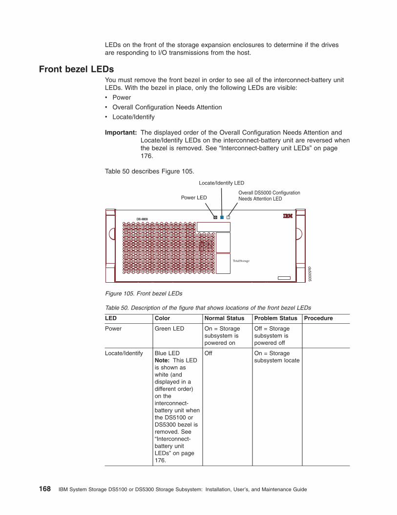
LEDs on the front of the storage expansion enclosures to determine if the drivesare responding to I/O transmissions from the host.
Front bezel LEDsYou must remove the front bezel in order to see all of the interconnect-battery unitLEDs. With the bezel in place, only the following LEDs are visible:
v Power
v Overall Configuration Needs Attention
v Locate/Identify
Important: The displayed order of the Overall Configuration Needs Attention andLocate/Identify LEDs on the interconnect-battery unit are reversed whenthe bezel is removed. See “Interconnect-battery unit LEDs” on page176.
Table 50. Description of the figure that shows locations of the front bezel LEDs
LED Color Normal Status Problem Status Procedure
Power Green LED On = Storagesubsystem ispowered on
Off = Storagesubsystem ispowered off
Locate/Identify Blue LEDNote: This LEDis shown aswhite (anddisplayed in adifferent order)on theinterconnect-battery unit whenthe DS5100 orDS5300 bezel isremoved. See“Interconnect-battery unitLEDs” on page176.
Off On = Storagesubsystem locate
Table 50 describes Figure 105.
Power LEDOverall DS5000 ConfigurationNeeds Attention LED
Locate/Identify LED
ds50005
Figure 105. Front bezel LEDs
168 IBM System Storage DS5100 or DS5300 Storage Subsystem: Installation, User’s, and Maintenance Guide

Table 50. Description of the figure that shows locations of the front bezel LEDs (continued)
LED Color Normal Status Problem Status Procedure
OverallConfigurationNeeds Attention
Amber LED Off On = There areone or morefailures in thestoragesubsystemconfiguration.The cause offailure could beone of thecomponents inthe chassis orone of thecomponents inthe attachedDS5100 orDS5300 storageexpansionenclosures.
“Troubleshootingthe storagesubsystem” onpage 166
RAID controller LEDs
Controller A
Controller B
ds50041
12
9
8
7
3
10
10
11
11
21
65
2 2 21 1 1
2 2 2 21 1 1 1
1 1 1 1 1 1 1 12 2 2 2 2 2 2 2
12
7
8
9
10 11
11 10
3 564
3 564
3 564
3 564
4 365 4 365 4 365 4
Figure 106. Fibre Channel RAID controller LEDs
Chapter 4. Operating the storage subsystem 169
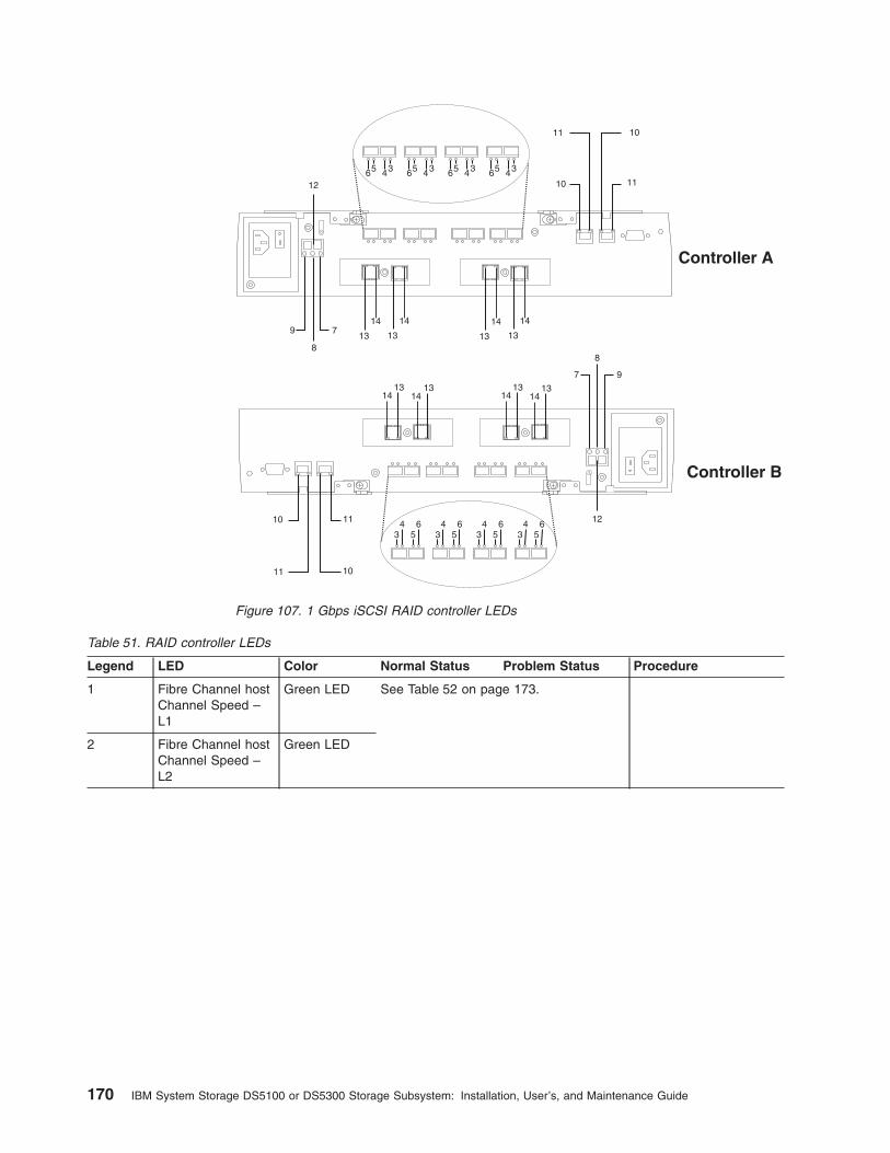
Table 51. RAID controller LEDs
Legend LED Color Normal Status Problem Status Procedure
1 Fibre Channel hostChannel Speed –L1
Green LED See Table 52 on page 173.
2 Fibre Channel hostChannel Speed –L2
Green LED
Controller A
Controller B
12
9
8
7
3
10
10
11
11
65
12
7
8
9
10 11
11 10
3 564
3 564
3 564
3 564
4 365 4 365 4 365 4
Figure 107. 1 Gbps iSCSI RAID controller LEDs
170 IBM System Storage DS5100 or DS5300 Storage Subsystem: Installation, User’s, and Maintenance Guide

Table 51. RAID controller LEDs (continued)
Legend LED Color Normal Status Problem Status Procedure
3 Drive Port Bypass(one LED per port)Note: The drivechannel consists oftwo FC ports. ThisLED indicates thedrive port bypassstatus of one of thetwo FC ports thatmade up a drivechannel. The LEDmarked 6 showsthe status of theother port.
Amber LED Off On = Bypassproblem
v An SFP moduleis inserted in theport and theconnected fibrechannel is eitherabsent or notproperlyconnected.
v The storageexpansionenclosureconnected to thisport is notpowered on.
v There is aproblem with thefibre channelconnectionbetween this portand the fibrechannel port ofthe connectedESM in thestorageexpansionenclosure.
4 Drive ChannelSpeed – L1
Green LED See Table 52 on page 173.
5 Drive ChannelSpeed – L2
Green LED
Chapter 4. Operating the storage subsystem 171

Table 51. RAID controller LEDs (continued)
Legend LED Color Normal Status Problem Status Procedure
6 Drive Port Bypass(one LED per port)Note: The drivechannel consists oftwo FC ports. ThisLED indicates thedrive port bypassstatus of one of thetwo FC ports thatmade up a drivechannel. The LEDmarked 3 showsthe status of theother port.
Amber LED Off On = Bypassproblem
v An SFP moduleis inserted in theport and theconnected fibrechannel is eitherabsent or notproperlyconnected.
v The storageexpansionenclosureconnected to thisport is notpowered on.
v There is aproblem with thefibre channelconnectionbetween this portand the fibrechannel port ofthe connectedESM in thestorageexpansionenclosure.
7 Service ActionAllowed
Blue LED Off On = Safe toremove
“Replacing a controller”on page 193
8 Needs Attention Amber LED Off On = Controllerneeds attention
There is a controllerfault or a controlleris offline.
Troubleshooting thestorage subsystem
9 Cache Active Green LED On = Data incache
Off = No data incache
Not applicable
10 Ethernet LinkSpeed
Green LED Off = 10BASE-T
On = 100BASE-T
Not applicable
172 IBM System Storage DS5100 or DS5300 Storage Subsystem: Installation, User’s, and Maintenance Guide
Table 51. RAID controller LEDs (continued)
Legend LED Color Normal Status Problem Status Procedure
11 Ethernet LinkActivity
Green LED Off = No linkestablished
On = Linkestablished
Flashing = Activity
LED is off when aEthernet cable isconnected:
v Check to see whetherthere are problemswith the Ethernetcables or switch.
v Verify that the Ethernetcontroller is not offline.
v Verify that thecontroller Ethernet porthas not been disabled.
v Verify that thecontroller Ethernet portis not bad.
12 Numeric Display(enclosure ID andDiagnostic Display)
Green/yellowseven-segmentdisplay
Diagnostic LED = flashing: Controller enclosure ID is displayed
Diagnostic LED = on: Diagnostic code is displayed
The Diagnostic LED is located on the Numeric Display. See“Seven-segment numeric display LEDs” on page 174.
13 iSCSI Host LinkSpeed
Green LED Off = 100BASE-T
On = 1000BASE-T
Not applicable
14 iSCSI Host LinkActivity
Green LED Off = No linkestablished
On = Linkestablished
Flashing = Activity
LED is off when aiSCSI cable isconnected:
v Check to see whetherthere are problemswith the iSCSI cablesor iSCSI switch.
v Verify that thecontroller is not offline.
v Verify that the switchport that the controlleriSCSI port isconnected to has notbeen disabled.
v Verify that thecontroller iSCSI port isnot bad using theEthernet portloopback.
The L1 and L2 LEDs for each host and drive channel combine to indicate the statusand the operating speed of each host or drive channel.
Table 52. Host and drive channel LED definitions
L1 L2 Definition
Off Off When both LEDs for a host or drive channel are off, thisindicates one or more of the following conditions:
v The host or drive channel ports are bad.
v An SPF module is inserted with no fibre channel cableattached.
v No SFP module is inserted in one or both of the host ordrive ports in the channel.
Chapter 4. Operating the storage subsystem 173

Table 52. Host and drive channel LED definitions (continued)
L1 L2 Definition
On Off The host channel is operating at 1 Gbps for host channelson a 4 Gbps HIC or is operating at 2 Gbps for host channelson a 8 Gbps HIC. This is not a valid condition for drivechannels.
Off On The host or drive channel is operating at 2 Gbps. For thehost channels on the 8 Gbps HIC, the port is operating at 4Gbps
On On The host or drive channel is operating at 4 Gbps. For thehost channels on the 8 Gbps HIC, the port is operating at 8Gbps
Seven-segment numeric display LEDsThe seven-segment numeric display LEDs provide information about enclosureidentification and diagnostics. Figure 108 shows the numeric display LEDs and theheartbeat and diagnostic LEDs.
When you turn on the power to the storage or storage enclosure, the numericdisplay LEDs cycle through various codes as the controller or ESM firmware startsto boot. If the diagnostic LED is illuminated and the heartbeat LED is turned off, itindicates that diagnostic information is displayed on the numeric display. When thecontroller completes the boot process and is operating normally, the diagnostic LEDturns off, the heartbeat LED flashes, and the numeric display changes to show theenclosure identification (enclosure ID) for that individual enclosure.
If an error occurs during the boot process and the Needs Attention LED is on, thenumeric display shows diagnostic information as sequence of 2-digit diagnosticcode. The number of time each 2-digit code is displayed during a sequence is fixedand under hardware control. Each sequence minimally consists of a two-digitcategory code, followed by a two-digit detail code that is specific to the category.Longer sequences can be displayed if more than one event is to be reported. Thisnominally consists of a series of category-detail sequences with a delimiter betweeneach category-detail sequence. The entire display goes blank at the end of thesequence (all segments off, the diagnostic light off), and then the sequence repeats.
A
D
BF
CE
G
SSD 1
D
A
EC
FB
G
SSD 2
DP
DP
Diagnostic Light
Heartbeat Light
Lower DigitUpper Digit
dcsi0
038
Figure 108. Numeric display LEDs
174 IBM System Storage DS5100 or DS5300 Storage Subsystem: Installation, User’s, and Maintenance Guide
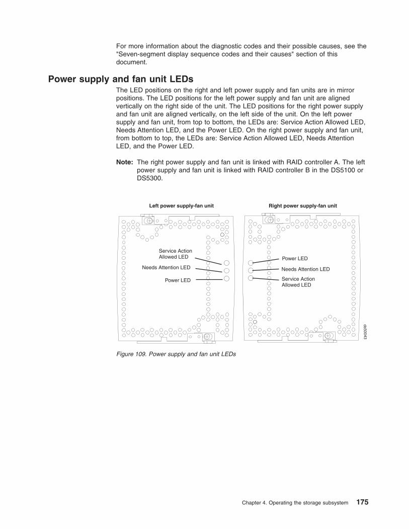
For more information about the diagnostic codes and their possible causes, see the"Seven-segment display sequence codes and their causes" section of thisdocument.
Power supply and fan unit LEDsThe LED positions on the right and left power supply and fan units are in mirrorpositions. The LED positions for the left power supply and fan unit are alignedvertically on the right side of the unit. The LED positions for the right power supplyand fan unit are aligned vertically, on the left side of the unit. On the left powersupply and fan unit, from top to bottom, the LEDs are: Service Action Allowed LED,Needs Attention LED, and the Power LED. On the right power supply and fan unit,from bottom to top, the LEDs are: Service Action Allowed LED, Needs AttentionLED, and the Power LED.
Note: The right power supply and fan unit is linked with RAID controller A. The leftpower supply and fan unit is linked with RAID controller B in the DS5100 orDS5300.
Power LED
Needs Attention LED
Service ActionAllowed LED
Power LED
Needs Attention LED
Service ActionAllowed LED
Right power supply-fan unitLeft power supply-fan unit
ds50043
Figure 109. Power supply and fan unit LEDs
Chapter 4. Operating the storage subsystem 175

Table 53. Power supply and fan unit LEDs
LED Color Normal Status Problem Status Procedure
Power Green LED On = Powersupply and fanunit is providingpower
Off = Powersupply and fan unitis not providingpower
Examine the power supplyand fan unit, connectedPDUs, and connectedpower circuits for any of thefollowing conditions:
v The power supply andfan unit power switch isoff.
v A circuit breaker hastripped in the controllerlinked to this powersupply and fan unit islinked. (The right powersupply and fan unit islinked to controller A; theleft power supply and fanunit is linked to controllerB.)
v The connected PDUs areturned off or have beentripped.
v There is no power at thewall circuit.
v The power supply andfan unit is bad.
NeedsAttention
Amber LED Off On = Powersupply and fan unitneeds attention
“Troubleshooting thestorage subsystem” onpage 166
ServiceActionAllowed
Blue LED Off On = Safe toremove
“Resetting the controllercircuit breakers” on page181
“Replacing a power supplyand fan unit” on page 205
Interconnect-battery unit LEDs
176 IBM System Storage DS5100 or DS5300 Storage Subsystem: Installation, User’s, and Maintenance Guide

Table 54. Interconnect-battery unit LEDs
Legend LED Color Normal Status Problem Status/Procedure
1 BatteryNeedsAttention
Amber LED Off On = Battery failed
See “Replacing a backup batterypack” on page 213.
2 Power Green LED On = storagesubsystem ispowered on
Off = storage subsystem ispowered off
If the storage subsystem ispowered on but this LED remainsoff, examine the power supply andfan units, the connected PDUs,and the connected power circuitsfor any of the following conditions:
v Both power supply and fan unitsare not turned on.
v A circuit breaker has tripped.
v The connected PDUs are turnedoff or have been tripped.
v There is no power at the wallcircuit.
v The interconnect-battery unit isbad.
Figure 110. Interconnect-battery unit LEDs
Chapter 4. Operating the storage subsystem 177

Table 54. Interconnect-battery unit LEDs (continued)
Legend LED Color Normal Status Problem Status/Procedure
3 OverallConfigurationNeedsAttention
Amber LED Off On = A component in the storagesubsystem configuration hasdeveloped a fault.
Inspect the Needs Attention LEDson the other components in theStorage Subsystem and in allconnected storage expansionenclosures to isolate the fault.
However, it is best practice to usethe DS Storage ManagerSubsystem Management windowto identify the cause of theproblem and use the RecoveryGuru to help fix the problems.Some of the problems may notcause the Needs Attention LED onthe individual FRU to light, but theywill cause this OverallConfiguration Needs Attention LEDto light. For example, a hard diskdrive that exceeds its PFA errorswill cause this LED to light, but thedrive Needs Attention LED for theindividual drive in the attachedstorage expansion enclosure willnot light.
See “Troubleshooting the storagesubsystem” on page 166.
4 Locate/Identify
White LEDNote: ThisLED isshown asblue (anddisplayed ina differentorder) whenthe DS5100or DS5300bezel isinstalled.See “Frontbezel LEDs”on page168.
Off On = storage subsystem locate
5 ServiceActionAllowed
Blue LED Off On = Safe to remove
See “Replacing theinterconnect-battery unit” on page209.
6 BatteryNeedsAttention
Amber LED Off On = Battery failed
See “Replacing a backup batterypack” on page 213.
178 IBM System Storage DS5100 or DS5300 Storage Subsystem: Installation, User’s, and Maintenance Guide
The Power, Overall Configuration Needs Attention, and Locate LEDs are generalindicators for the entire storage subsystem (or configuration, in the case of theOverall Configuration Needs Attention), not specifically for the interconnect-batteryunit. The Overall Configuration Needs Attention LED turns on if a fault condition isdetected in any component in the storage subsystem configuration, including allattached storage expansion enclosures. The Power, Overall Configuration NeedsAttention, and Locate LEDs shine through the front bezel.
Attention: If the Overall Configuration Needs Attention LED lights, refer to the DSStorage Manager client software to determine the problem with the storagesubsystem. Also, inspect the Needs Attention LEDs on the other components in thestorage subsystem to help isolate the fault to a specific component.
Recovering from an overheated power supply and fan unitThe storage subsystem has two power supply and fan units. Each power supplyand fan unit contains a power supply, a cooling fan, a battery charger, and a built-intemperature sensor designed to prevent the power supplies from overheating.Under normal operating conditions, with an ambient air temperature range of 10° Cto 35° C (50° F to 95° F), the cooling fans maintain a proper operating temperatureinside the storage subsystem.
Several factors can cause the power supplies to overheat. These factors include thefollowing:
v Unusually high room temperature
v Fan failure
v Defective circuitry in the power supply
v Blocked air vent
v Failure in other devices installed in the cabinet
If the internal temperature rises above 70° C (158° F), one or both power suppliesautomatically shut down. If one power supply shuts down, the DS Storage Managerclient software displays a Needs Attention status in the Subsystem Managementwindow, the alarm sounds (if enabled), and the Overall Configuration NeedsAttention LED on the front bezel of the storage subsystem turns on.
If a common environmental stress causes both power supplies to shut down, thestorage subsystem shuts down, and the DS Storage Manager client softwaredisplays a Not Responding status in the Subsystem Management window.
If event monitoring is enabled and event notification is configured, the software alsoissues critical event notifications.
v Nominal temperature exceeded – The storage subsystem temperature exceedsthe normal operating range.
v Maximum temperature exceeded – The storage subsystem temperature exceeds70° C (158° F).
Use the following procedure to resume normal operation after a power supplyshutdown.
Attention: Power supplies automatically shut down when air temperature insidethe cabinet reaches 70° C (158° F) or above. If the power supplies have shut down,immediately remove all cabinet panels to help cool the cabinet air temperature andprevent damage to the storage subsystem.
Chapter 4. Operating the storage subsystem 179

Note: If both power supply and fan units have shut down, start with step 4 below.
1. If applicable, turn off the alarm.
2. Use the DS Storage Manager client software to print a storage subsystemprofile.
3. In the DS Storage Manager client Subsystem Management window, selectAdvanced � Troubleshooting � View Event Log to display the critical events.Look for one of the following critical event entries:
v Event 281B - Nominal temperature exceeded
v Event 281C- Maximum temperature exceeded
4. Try alleviating the overheating problem by doing the following:
v Removing all panels from the cabinet.
v Cooling the area using external fans.
v Shutting down the power to the storage subsystem or storage expansionenclosures (Follow the power-down procedure described in “Turning off thestorage subsystem” on page 157.)
5. Stop all I/O activity to the storage subsystem and to all attached storageexpansion enclosures.
6. Wait until the ambient air temperature around the storage subsystem cools.
The storage subsystem is capable of power-up recovery without operatorintervention after the temperature inside the power supply and fan unit cools tobelow 70° C (158° F). After the air has cooled, the power supplies should turnon automatically. If the power supplies restart automatically, the controllersreset and return to normal operation.
7. Did the power supplies restart automatically?
v Yes – Go to step 9.
v No – Go to step 8.
8. Turn off the power switch on each controller in the storage subsystem andthen power off all connected storage expansion enclosures. Wait 1 minute andthen turn on power to all connected storage expansion enclosures and then tothe storage subsystem. If the power supplies go into operation, go to step 9. Ifnot, call your IBM service representative.
9. Check the status LEDs on the front and back of the storage subsystem.
For information about storage subsystem LEDs, see “Checking the LEDs” onpage 167.
10. Are the LEDs on the storage subsystem indicating normal status?
v Yes – Go to step 11.
v No – Go to step 12.
11. Use the DS Storage Manager client software to check the status of all storagesubsystems in the configuration. Is the status Optimal for each storagesubsystem?
v Yes – End of procedure. Resume normal operation.
v No – Go to step 12.
12. Diagnose and correct the fault by completing the following steps:
a. Select the Recovery Guru toolbar button in the Subsystem Managementwindow to run the Recovery Guru.
b. Complete the recovery procedure.
180 IBM System Storage DS5100 or DS5300 Storage Subsystem: Installation, User’s, and Maintenance Guide

If the Recovery Guru directs you to replace a failed component, use theindividual LEDs on the storage subsystem to locate the specific failedcomponent.
c. When the procedure is completed, select Recheck in the Recovery Guru.This will rerun the Recovery Guru to ensure that the problem has beenfixed.
d. If the problem has not been fixed contact your IBM service representative.
Print a storage subsystem profile and save the storage subsystem supportdata. The profile and support data will be helpful when troubleshootingstorage subsystem problems. (For information about printing a storagesubsystem profile and saving the support data, refer to the SubsystemManagement window online help.)
Resetting the controller circuit breakersEach storage subsystem controller has one circuit breaker that providesover-current protection to the power supply in a power supply and fan unit. Thecircuit breaker is mounted inside the controller, in line with the internal power cable.The circuit breaker provides protection for ac input.
The internal power cable runs from the ac connector on a controller to the powersupply in a power supply and fan unit. Power to the right power supply and fan unit(as viewed from the front of the storage subsystem) is routed through the topcontroller (controller A); power to the left power supply and fan unit is routedthrough the bottom controller (controller B).
If a circuit breaker has tripped, the condition might appear as if a power supply andfan unit has failed. The power supply is no longer providing power to the storagesubsystem. A tripped circuit breaker is indicated when all of the following conditionsare present:
v The Overall Configuration Needs Attention LED on the storage subsystem frontbezel is turned on.
v The controller Needs Attention LEDs are not turned on.
v The power supply and fan unit Needs Attention LEDs are not turned on.
v The Service Action Allowed LED is turned on for the power supply and fan unitconnected to the controller with the open circuit breaker.
v The DS Storage Manager client shows the power supply and fan unit has failed.
Use the following procedure to reset the circuit breaker.
Tools and Equipment
v Anti-static protection
v Nonconducting stylus
Electrostatic discharge can damage sensitive components – Touching thestorage subsystem or its components without using a proper ground might damagethe equipment. To avoid damage, use proper anti-static protection while handlingany components.
1. If the alarm is sounding, turn off the alarm.
2. Check to ensure that the external power cables are completely plugged intothe controllers and into the power source.
3. Put on anti-static protection.
Chapter 4. Operating the storage subsystem 181
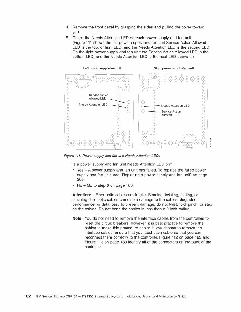
4. Remove the front bezel by grasping the sides and pulling the cover towardyou.
5. Check the Needs Attention LED on each power supply and fan unit.(Figure 111 shows the left power supply and fan unit Service Action AllowedLED is the top, or first, LED, and the Needs Attention LED is the second LED.On the right power supply and fan unit the Service Action Allowed LED is thebottom LED, and the Needs Attention LED is the next LED above it.)
Is a power supply and fan unit Needs Attention LED on?
v Yes – A power supply and fan unit has failed. To replace the failed powersupply and fan unit, see “Replacing a power supply and fan unit” on page205.
v No – Go to step 6 on page 183.
Attention: Fiber-optic cables are fragile. Bending, twisting, folding, orpinching fiber optic cables can cause damage to the cables, degradedperformance, or data loss. To prevent damage, do not twist, fold, pinch, or stepon the cables. Do not bend the cables in less than a 2-inch radius.
Note: You do not need to remove the interface cables from the controllers toreset the circuit breakers; however, it is best practice to remove thecables to make this procedure easier. If you choose to remove theinterface cables, ensure that you label each cable so that you canreconnect them correctly to the controller. Figure 112 on page 183 andFigure 113 on page 183 identify all of the connectors on the back of thecontroller.
Needs Attention LED
Service ActionAllowed LED
Needs Attention LED
Service ActionAllowed LED
Right power supply-fan unitLeft power supply-fan unit
ds50046
Figure 111. Power supply and fan unit Needs Attention LEDs
182 IBM System Storage DS5100 or DS5300 Storage Subsystem: Installation, User’s, and Maintenance Guide

6. Use the DS Storage Manager client software to take the controller offline. Afterthe controller is offline, the Service Action Allowed LED turns on, and you cansafely remove the controller.
7. Slide the controller with the open circuit breaker from the storage subsystem.You do not need to completely remove the controller. Only slide it out farenough to reveal the holes over the circuit breakers.
a. Using your index fingers, simultaneously push the latches to release thelevers, and rotate the levers to disengage them from the locking pins.
b. Use the levers to slide the controller from the storage subsystem chassis.(Figure 114 on page 184 shows a controller sliding from the storage
RS-232serial portEthernet portsDual-ported
drive channels
ACpower
Controller A
Strain-reliefclamp
ACpowerStrain-relief
clampEthernet portsRS-232serial port Dual-ported
drive channels
Controller B
Fibre Channel host ports
Fibre Channel host ports
Figure 112. RAID controller connections with Fibre Channel host connections
iSCSI host channels
RS-232serial port
Ethernet portsDual-porteddrive channels
ACpower
Controller A
Strain-reliefclamp
ACpower
Strain-reliefclampEthernet ports
RS-232serial port
Dual-porteddrive channels
Controller B
Figure 113. RAID controller connections with iSCSI host connections
Chapter 4. Operating the storage subsystem 183

subsystem chassis.)
8. Insert a nonconducting stylus through the appropriate hole in the cover of thecontroller and press down gently. Figure 115 shows the location of the circuitbreaker access hole in the controller B cover.
Note: When controllers A and B are inserted in the controller slots, thelocation of the circuit breaker access hole is as follows. On controller A,the circuit breaker access hole is located on the left side on the bottomof the controller. On controller B, the circuit breaker access hole islocated on the right side on the top of the controller (as shown inFigure 115).
RAID controllers
Levers in releasedposition
Latches
ds50045
Figure 114. Removing the controller from the storage subsystem
AC circuit breaker
ds50044
Figure 115. Circuit breaker access hole
184 IBM System Storage DS5100 or DS5300 Storage Subsystem: Installation, User’s, and Maintenance Guide

9. Reset the circuit breaker that tripped by pressing down with the stylus on therocker switch.
10. Slide the controller into the storage subsystem chassis.
a. Holding both levers, slowly push the controller until the notches in both theleft and right levers are aligned with the pins on the DS5100 or DS5300enclosure so that the controller is pulled evenly into the DS5100 orDS5300 chassis, ensuring full electrical connection contact on all interfacepins.
Attention: Verify that the controller does not snag any other DS5100 orDS5300 cables when you slide it into the controller bay.
b. Press the controller fully into the slot, engaging the pins on the enclosure.
c. Hold open both latches and push both left and right levers simultaneouslyto the closed position. Release the latches. When you release the latches,you should hear both latches snap over the levers, indicating that thecomponent is locked in place.
11. If you removed the interface cables, reconnect all host interface cables anddrive interface cables, including the SFP modules.
12. Wait up to 5 minutes for the DS Storage Manager client software to recognizethe controller.
13. Complete any remaining Recovery Guru procedures for controller replacement,if needed.
14. Based on the Host Channel Speed, Drive Channel Speed, and NeedsAttention LED status, proceed to one of the following steps:
v All channel speed LEDs are on and the Needs Attention LED is off – Go tostep 16.
v All channel speed LEDs are off or the Needs Attention LED is on – Verifythe controller has been installed correctly. Remove and reinstall thecontroller. Go to step 15.
Note: If a host channel or drive channel does not have a cable connected,the channel speed LEDs are not illuminated.
15. Did this action correct the problem?
v Yes – Go to step 16.
v No – If the problem has not been fixed, contact your IBM servicerepresentative.
16. Remove the anti-static protection.
17. Install the front bezel by aligning the pins on the storage subsystem chassiswith the spring-steel retainers on the cover and then pressing the cover towardthe chassis until the pins snap into place.
18. Using the Enterprise Management window, view the status of the storagesubsystems. Do any storage subsystems indicate Needs Attention?
v Yes – Go to step 19.
v No – All components display Optimal status. You are finished with thisprocedure.
19. Use the Subsystem Management window to check the status of all storagesubsystems in the configuration.
20. Do any storage subsystems have a Overall Configuration Needs Attentionstatus?
Chapter 4. Operating the storage subsystem 185

a. Yes – Select the Recovery Guru toolbar button in the SubsystemManagement window, and complete the recovery procedure. If the problempersists, contact your IBM service representative.
b. No – Contact your IBM service representative. Print a storage subsystemprofile, and save the storage subsystem support data. The profile andsupport data are helpful when troubleshooting storage subsystemproblems. (For information about printing a storage subsystem profile andsaving the support data, refer to the Subsystem Management windowonline help.)
Cache memory and cache batteryEach RAID controller in the DS5100 or DS5300 contains cache memory to storeread and write operations. (Both RAID controllers in the DS5100 or DS5300 musthave the same amount of cache memory.) The interconnect-battery unit containstwo Lithium Ion battery packs that can maintain power to the RAID controllercaches for up to thirty minutes to flush cache memory to flash memory modules inthe event that the DS5100 or DS5300 lose power.
Important:
Do not replace the battery until it is marked failed by the controller. If the batteriesare shown as expired, use the reset battery age function in the SM clientsubsystem management window to reset the age.
Attention: There are different replacement FRU part numbers for the controllerwith certain cache sizes. The storage subsystem profile has the information on theinstalled cache memory size in the controllers. Refer to the storage subsystemprofile and see “Parts list” on page 238 for the correct FRU part number for thecontroller.
Cache memoryCache memory is memory on the RAID controller that is used for intermediatestorage of read and write data on the DS5100 or DS5300 RAID controllers. Usingcache memory can increase system performance. The data for a read operationfrom the host might be in the cache memory from a previous operation (thuseliminating the need to access the drive itself), and a write operation is completedwhen it is written to the cache, rather than to the drives.
The RAID controller has a Cache Active LED that displays the current status of thecache. The LED is on if there is data in the cache, and it is off if there is no data inthe cache.
If caching is enabled and the Cache Active LED never comes on during I/O activity,it indicates one of the following conditions:
v The cache memory from either controller A or controller B failed.
v The cache sizes in controller A and controller B are not the same.
v The battery failed. (In this case, one or both of the green Battery LEDs will be offand one or both amber Battery Needs Attention LEDs will be lit.)
Note: Always use the DS Storage Manager client to check your cache memorysettings before assuming a hardware failure.
186 IBM System Storage DS5100 or DS5300 Storage Subsystem: Installation, User’s, and Maintenance Guide

Figure 116 shows the locations of the Cache Active LEDs on the front of the RAIDcontrollers.
Subsystem cache batteryThe DS5100 or DS5300 interconnect-battery unit contains two battery packs thatprovide backup power to maintain any cached data not written to disks in the eventof a power loss. The battery packs can provide power to the data caches in theRAID controllers for up to thirty minutes for the controllers to flush cache memory toflash memory modules in the event of power loss.
Statement 2:
CAUTION:When replacing the lithium battery, use only an equivalent type batteryrecommended by the manufacturer. If your system has a module containing alithium battery, replace it only with the same module type made by the samemanufacturer. The battery contains lithium and can explode if not properlyused, handled, or disposed of.
Do not:
v Throw or immerse into water
v Heat to more than 100° C (212° F)
v Repair or disassemble
Dispose of the battery as required by local ordinances or regulations.
Replace the battery packs in the DS5100 or DS5300 interconnect-battery unit whenthey are identified as failing by the DS Storage Manager Subsystem Managementwindow, or when the Battery LEDs or Battery Needs Attention LEDs light. (TheseLEDs are located on the power supply and fan units and on the interconnect-batteryunit respectively, as shown in Figure 117 on page 188.)
Replace only the battery pack that is indicated as failed by the LEDs or in the DSStorage Manager Subsystem Management window. You do not need to replaceboth battery packs when the Battery LEDs indicate that only one battery pack failed.
Controller A
ds50010
Controller B
Cache active LED
Cache active LED
Figure 116. Cache Active LEDs
Chapter 4. Operating the storage subsystem 187

In the event that the battery age expires, do not call on IBM technical support toreplace the battery. Instead, reset the battery age using the procedure described inthe Storage Manager online help. You should only replace the battery when it is in afailed state, as reported by the Storage Manager Recovery Guru.
The interconnect-battery unit also has a battery failure indicator LED for eachbattery pack that is located on the interconnect-battery unit. This LED will light if thebattery fails to hold a charge.
The battery performs a self-test at startup and every 25 hours thereafter (duringwhich time the Battery LED flashes). If necessary, the battery begins recharging atthat time. If the battery fails the self-test, the Battery LED turns off, indicating abattery fault.
Data caching starts after the battery completes the startup tests.
Figure 117 shows the location of the Battery Needs Attention LEDs on theinterconnect-battery unit.
Battery Needs Attention LED Battery Needs Attention LED
ds50011
Figure 117. Battery LEDs
188 IBM System Storage DS5100 or DS5300 Storage Subsystem: Installation, User’s, and Maintenance Guide

Chapter 5. Replacing components
This chapter lists replacement parts and explains the procedures for replacing acontroller, a power supply and fan unit, an interconnect-battery unit, and an SFPmodule. Before using the procedures in this chapter, perform the appropriatetroubleshooting steps described in “Troubleshooting the storage subsystem” onpage 166, and in the Recovery Guru.
The following list shows the components that you can replace on site. To orderparts, contact your IBM service representative.
v RAID controllers
v Power supply and fan units (containing power supplies, fans, and batterychargers)
v Interconnect-battery unit (containing the midplane and batteries for the cachebackup)
v SFP modules
v Interface cables
v Ethernet cables
Attention: Never remove the interconnect-battery unit unless directed to do so byan IBM Service representative. Refer to “Replacing the interconnect-battery unit” onpage 209 for complete information about the conditions required for safe removal ofthe interconnect-battery unit. Also, make sure you replace the interconnect-batteryunit within 15 minutes. If you take longer, it may result in overheating of the chassis.
Instructions are also provided to help you add new DS5100 or DS5300 storageexpansion enclosures to existing DS5100 or DS5300 configuration.
You can perform all replacement procedures in this chapter as hot-swapprocedures. Hot swap refers to the ability to remove and replace a storagesubsystem component while the storage subsystem is under power and processingdata. The DS5100 or DS5300 has three major components you can replace on site:the controller, power supply and fan unit, and interconnect-battery unit. In a fullyconfigured storage subsystem, the controllers and power supply and fan units areredundant. If any one of these redundant components fails, the component can bereplaced without powering off the storage subsystem, and without interrupting dataprocessing.
For more FRU and Option part number information, see the following Web site:
www.ibm.com/systems/support/storage/disk
Handling static-sensitive devices
Attention: Static electricity can damage electronic devices and your system. Toavoid damage, keep static-sensitive devices in their static-protective packages untilyou are ready to install them.
To reduce the possibility of electrostatic discharge, observe the followingprecautions:
v Limit your movement. Movement can cause static electricity to build up aroundyou.
© Copyright IBM Corp. 2008, 2012 189

v Handle the device carefully, holding it by its edges or its frame.
v Do not touch solder joints, pins, or exposed printed circuitry.
v Do not leave the device where others can handle and possibly damage thedevice.
v While the device is still in its static-protective package, touch it to an unpaintedmetal part of the storage subsystem for at least two seconds. This drains staticelectricity from the package and from your body.
v Remove the device from its package and install it directly into your storagesubsystem without setting it down. If it is necessary to set the device down, placeit in its static-protective package. Do not place the device on your storagesubsystem cover or any metal surface.
v Take additional care when handling devices during cold weather because heatingreduces indoor humidity and increases static electricity.
Service Action Allowed status LEDEach controller, power supply and fan unit, and battery unit has a blue ServiceAction Allowed status LED. The purpose of the Service Action Allowed status LEDis to help ensure that a component is not removed before it is safe to do so. Do notremove any storage subsystem component unless the component's Service ActionAllowed status LED is lit.
AttentionNever remove a controller, power supply and fan unit, or interconnect-batteryunit unless the Service Action Allowed status LED is turned on. Doing so canresult in a potential loss of data. If the Needs Attention LED is lit and theassociated Service Action Allowed status LED is not lit, then you must performadditional diagnostics before you can remove the indicated component. Usethe Recovery Guru instructions in the DS Storage Manager SubsystemManagement window or refer to the appropriate component replacementinstructions for the additional diagnostics required in this case.
The Service Action Allowed status LED automatically turns on or off as conditionschange. Wait at least two minutes after you replace each component for thecontroller to recognize the new component and update the LED status. In mostcases when a single component fails, the Service Action Allowed status LED turnson steadily when the Needs Attention status LED is turned on for the component.
Single component failuresWhen a single component in the DS5100 or DS5300 fails, the following listindicates the behavior of the Service Action Allowed status LED lights:
v If a controller or power supply and fan unit fails and needs to be replaced, theamber Needs Attention status LED on that component turns on to indicate that aservice action is required. If there are no data availability dependencies or otherconditions that dictate that the component should not be removed, the blueService Action Allowed status LED turns on. Do not remove any componentsother than the component indicated by the lit blue Service Action Allowed statusLED.
v The interconnect-battery unit contains the midplane that communicates betweencontrollers A and B in the DS5100 or DS5300. If the interconnect-battery unitneeds to be replaced, the Service Action Allowed status LED does notautomatically turn on. Before the interconnect-battery unit Service Action Allowed
190 IBM System Storage DS5100 or DS5300 Storage Subsystem: Installation, User’s, and Maintenance Guide

status LED can turn on, you must use the DS Storage Manager client to placecontroller B offline. (Controller A is the controller designated to receive all I/Oactivity when the interconnect-battery unit is removed from the storagesubsystem.) By placing controller B offline, you route all controller and I/O activitythrough controller A. This maintains data availability while the interconnect-batteryunit is removed, preventing any problems that would normally arise from the lossof communication between controllers A and B.
Attention: Before you remove the interconnect-battery unit, you must verifythat controller A is in an optimal state, and the power supply and fan unit FRUthat is connected to controller A (the right power supply) is optimal. Neverremove the interconnect-battery unit when controller A or the power supply andfan unit FRUs are not in an optimal state.
Multiple component failuresWhen multiple components in the DS5100 or DS5300 fails, the behavior of theService Action Allowed and Needs Attention LEDs can vary from situation tosituation. In some cases, multiple Service Action Allowed status LEDs light whentheir corresponding Needs Attention LEDs are lit. In other cases, none of theService Action Allowed status LEDs light when their corresponding Needs AttentionLEDs are lit. This variance exists because the ability to remove a componentdepends on the different data availability dependencies of the storage subsystemcomponents.
If replacing any one of the multiple components that have their Needs AttentionLEDs lit will cause the DS5100 or DS5300 to shut down, the Service Action Allowedstatus LEDs will not light on any of the components that need attention. Forexample, if both the right power supply and fan unit (which is linked to controller A)and controller B need attention, then neither of the Service Action Allowed statusLEDs on these components would light. Removing the controller B before replacingthe failed right power supply and fan unit would cause controller A to lose power,resulting in a loss of data availability. (This linkage exists because the powerdistribution from each power supply and fan unit runs through the controllerphysically connected to that power supply and fan unit.)
However, if replacing any one of the multiple components that have their NeedsAttention LEDs lit will not cause the DS5100 or DS5300 to shut down, then theService Action Allowed status LEDs will light on all of the components that needattention. For example, if the right power supply and fan unit (which is linked tocontroller A) and controller A both need attention, then the Service Action Allowedstatus LEDs on both of these components would light, indicating that eithercomponent can be replaced first.
Important: In this situation (in which replacing any one of the multiple componentsthat have their Needs Attention LEDs lit will not cause the DS5100 orDS5300 to shut down), after you remove one failed component, theService Action Allowed status LEDs on the remaining components thatneed attention might turn off. This change in the Service Action Allowedstatus LEDs indicates that removing additional components now mightcause the storage subsystem to shut down.
For example, if both power supply and fan units have failed, the NeedsAttention and the Service Action Allowed status LEDs would be lit forboth components. However, when you remove one power supply andfan unit from the system, the Service Action Allowed status LED on theremaining power supply and fan unit turns off, indicating that you now
Chapter 5. Replacing components 191

cannot remove the second power supply and fan unit (because thestorage subsystem requires that at least one power supply and fan unit,functioning or not, must be present in the storage subsystem at alltimes).
Releasing and locking a component leverEach component is secured into the storage subsystem chassis by two cam locklevers mounted to the component. The lever engages with a pin on the storagesubsystem chassis to pull the component securely into the chassis. The levers arelocked in place by spring-loaded latches. The control components have the leverson the same side. The power supply and fan units and the interconnect-battery unithave the one lever mounted to the top of the component and one lever mounted tothe bottom of the component. Figure 118 shows a component lever and the latchthat secures the lever. The top view shows the lever in the closed and latchedposition. The bottom view shows the lever in the released position.
To release both latches on a component and remove the component, complete thefollowing:
1. Push the latches to the side until the latches release the levers. Do not proceedwith the next step until you have released both levers from the latches.
2. Rotate both levers out simultaneously. Ensure that the levers are completelyfree of the pins. Then place one hand under the component and use the leversto pull the component from the DS5100 or DS5300.
Before you begin, ensure that you wear an anti-static wrist strap.
To replace a component and lock the latches, complete the following:
Latch
Lever
Pin
ds48024
Figure 118. Component lever and latch
192 IBM System Storage DS5100 or DS5300 Storage Subsystem: Installation, User’s, and Maintenance Guide

1. With both levers rotated out perpendicular to the face of the component, slidethe back of the component into the appropriate slot.
2. Push the component into the slot and, when the component is almost fullyinstalled, verify that the notches in both levers are aligned with the pins on thestorage subsystem. Verify this alignment to ensure that the component is pulledevenly into the storage subsystem, ensuring full electrical connection contact onall interface pins.
3. Press the component fully into the slot, engaging the pins on the storagesubsystem.
4. Hold open both latches and rotate both levers simultaneously to the closedposition. Release the latches. When you release the latches, you should hearboth latches snap over the levers. This indicates that the component is locked inplace.
Replacing a controller
Attention: Before you replace a RAID controller, verify the following:
v The replacement RAID controller part number matches the part number of theRAID controller to be replaced. To provide full functionality, the two controllersshould have the same memory capacity.
v Both power supply and fan units must be connected and powered on with nolighted Needs Attention LEDs. Ensure that the Power LEDs on each of the powersupply and fan units are lit. If either of the power supply and fan units is notoptimal, it is best practice to replace that component before you proceed with thecontroller replacement procedure.
v If you are replacing a functional controller, first make sure that the other RAIDcontroller is optimal and that the fibre channel path from the hosts to the otherRAID controller is also optimal.
v Be aware that each RAID controller has a unique hardware Ethernet address,which is printed on a label on the front.
v Ensure that you wear an anti-static wrist strap.
Use the following procedure to replace a controller in a DS5100 or DS5300.
1. Ensure you are ready with all the required instruments and components,including a Phillips screwdriver to unscrew the thumbscrews. Also, make surethat the power supply is not switched off for more than 15 minutes. If thepower supply is off for more than 15 minutes, it may lead to overheating of thechassis.
2. Use the DS Storage Manager client software to save a storage subsystemconfiguration and the subsystem Collect All Support Data (CASD) bundle.
3. If you are:
v Replacing a failed controller, locate the failed controller by checking theNeeds Attention status LEDs on the controllers in the storage subsystem(see Figure 119 on page 194). Skip to step 5 on page 194.
v Replacing a functional controller as requested by the IBM Supportpersonnel, go to step 4.
4. Prepare the controller for removal by performing the following steps:
a. Using the DS Storage Manager client software, on the SubsystemManagement window menu bar, click Advanced � Trouble Shooting �Prepare for Removal.
Chapter 5. Replacing components 193

b. On the Prepare for removal dialog window, in the Enclosure drop downmenu, select Controller Enclosure.
c. In the Component drop down menu, select the controller you want toremove.
Available controller options are controller in slot A or controller in slot B.
d. Click the Prepare for removal button.
The Service Action Allowed LED turns on (turns blue) on the controller youselected to remove.
e. Go to step 6.
5. Is the Service Action Allowed LED turned on?
Figure 119 shows the location of the Service Action Allowed status LED on theback of a controller.
Attention: Never remove a controller unless the Service Action Allowedstatus LED is turned on. Doing so can result in a potential loss of data.
v Yes – Go to step 6.
v No – Another component requires attention before you can remove thecontroller. Normally, this situation indicates that a power supply and fan unitis either powered off or failed. Ensure that both power supply and fan unitsare powered on and in an optimal state. If the Service Action Allowed LEDof the failed controller is unlit and both power supply and fan units are in anoptimal state, contact your IBM support representative.
Electrostatic discharge can damage sensitive components. Touching thestorage subsystem or its components without using a proper ground mightdamage the equipment. To avoid damage, use proper anti-static protectionwhile handling any components.
6. Put on anti-static protection.
7. (If applicable) Unpack the new controller. Save all packing materials in theevent you need to return the new controller.
8. (If applicable) Determine whether the replacement controller will serve ascontroller A or controller B. (Controller A is inserted in the top controller bay;controller B is inserted in the bottom controller bay.) Then apply the controllerlabels for host channels, drive channels, power inputs, and numeric display to
Controller A
ds50048
Controller B
Needs AttentionLED (amber)
Service Action AllowedLED (blue)
Service Action AllowedLED (blue)
Needs AttentionLED (amber)
Figure 119. RAID controller Needs Attention and Service Action Allowed LEDs
194 IBM System Storage DS5100 or DS5300 Storage Subsystem: Installation, User’s, and Maintenance Guide

the replacement controller. The controller labels and instructions are includedwith the replacement controller. Make sure that the labels are aligned properlyand do not cover any ports or LEDs.
Attention: Handle and install fiber-optic cables properly to avoid degradedperformance or loss of communications with devices. For specific handlingguidelines, see “Handling fibre-optic cables” on page 50.
9. Disconnect all attached interface cables from the controller you are upgradingor replacing, including the SFP modules. Ensure that you label each cable sothat you can reconnect them correctly to the new or upgraded controller.Figure 120 shows the location of the connectors on the back of a controller.
Use the following procedure to remove the SFPs from the RAID controller thatyou are replacing or upgrading:
a. Remove the LC-LC fibre-channel cable from the SFP module. For moreinformation, see “Handling fibre-optic cables” on page 50.
b. Unlock the SFP or SFP+ module latch:
v For SFP modules that contain plastic tabs, unlock the SFP module latchby pulling the plastic tab outward 10°, as shown in Figure 121 on page196.
Host channels
RS-232serial portEthernet portsDual-ported
drive channels
ACpower
Controller A
Strain-reliefclamp
ds50015
ACpowerStrain-relief
clampEthernet portsRS-232serial port Dual-ported
drive channels
Host channelsController B
Figure 120. Connectors on the back of each controller. Each host channel is different,dependent on the host interface card.
Chapter 5. Replacing components 195
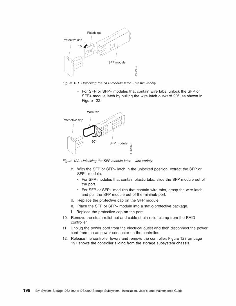
v For SFP or SFP+ modules that contain wire tabs, unlock the SFP orSFP+ module latch by pulling the wire latch outward 90°, as shown inFigure 122.
c. With the SFP or SFP+ latch in the unlocked position, extract the SFP orSFP+ module.
v For SFP modules that contain plastic tabs, slide the SFP module out ofthe port.
v For SFP or SFP+ modules that contain wire tabs, grasp the wire latchand pull the SFP module out of the minihub port.
d. Replace the protective cap on the SFP module.
e. Place the SFP or SFP+ module into a static-protective package.
f. Replace the protective cap on the port.
10. Remove the strain-relief nut and cable strain-relief clamp from the RAIDcontroller.
11. Unplug the power cord from the electrical outlet and then disconnect the powercord from the ac power connector on the controller.
12. Release the controller levers and remove the controller. Figure 123 on page197 shows the controller sliding from the storage subsystem chassis.
Protective cap
SFP module
10o
Plastic tab
F10ug009
Figure 121. Unlocking the SFP module latch - plastic variety
Protective cap
SFP module90o
Wire tab
F10ug010
Figure 122. Unlocking the SFP module latch - wire variety
196 IBM System Storage DS5100 or DS5300 Storage Subsystem: Installation, User’s, and Maintenance Guide

13. Remove the following cards from the controller you removed in step 12 onpage 196 and install in the new (replacement) controller. Use the same slots inthe new controller:
v Host interface card
For instructions on how to remove and replace host interface cards, seesteps 12 -24 “Replacing a DS5100 or DS5300 host interface card” on page199 or refer to the following publication: Installing or replacing a DS5000host interface card.
v Cache memory card
v Flash memory card
For instructions on how to remove and replace these cards, refer to thefollowing publication: Installing or replacing a DS5000 cache or flashmemory card.
14. Find the label on the top of the new or upgraded controller and record itsmedia access control (MAC) address.
15. Install the new or replacement controller by performing the following:
a. Carefully position the controller at the back of the storage subsystemchassis. Ensure that the controller can slide into the storage subsystemchassis without obstruction.
b. With the left and right levers rotated out perpendicular to the face of thecontroller, slide the back of the controller into the appropriate slot.
c. Push on both sides of the controller so that it slides into the slot evenly.Stop inserting the controller when it is about 1 inch from being fully insertedinto the slot. With the controller not fully inserted in the slot, attach all theSFPs and cables that you disconnected from the failed controller in step 9on page 195.
1) Replace the SFPs into the appropriate ports. See “Installing SFP orSFP+ modules” on page 51.
2) Reconnect all cables, including all host and drive channel cables andsecondary cables (such as Ethernet connections).
RAID controllers
Levers in releasedposition
Latches
ds50045
Figure 123. Removing a controller from the DS5100 or DS5300
Chapter 5. Replacing components 197

d. Holding both levers, slowly push the controller until the notches in both theleft and right levers are aligned with the pins on the DS5100 or DS5300enclosure so that the controller is pulled evenly into the DS5100 orDS5300 chassis, ensuring full electrical connection contact on all interfacepins.
Attention: Verify that the controller does not snag any other DS5100 orDS5300 cables when you slide it into the controller bay.
e. Press the controller fully into the slot, engaging the pins on the enclosure.
f. Hold open both latches and push both left and right levers simultaneouslyto the closed position. Release the latches. When you release the latches,you should hear both latches snap over the levers, indicating that thecomponent is locked in place.
16. Wrap the strain-relief clamp around the power cord approximately 20 cm (8 in.)from the controller connection end. Leave some slack between the clamp andthe controller end of the power cord. Replace the strain-relief nut and tighten itsecurely to secure the clamp to the controller unit.
17. Connect the power cord to the ac power connector of the controller youreplaced or upgraded. Plug the power cord into a properly grounded electricaloutlet.
18. Wait up to 5 minutes for the DS Storage Manager client software to recognizethe controller you replaced or upgraded.
19. Complete any remaining Recovery Guru procedures for controller replacement,if needed.
20. Check the LEDs on the controller to verify that the controller is fullyoperational. See “RAID controller LEDs” on page 169.
The LEDs come on and go off intermittently for approximately 60 seconds orpossibly longer. After this time, you are able to discover the controller throughthe DS Storage Manager software.
21. Remove the anti-static protection.
22. Use the DS Storage Manager client Subsystem Management window to checkthe status of all components in the storage subsystem.
v If the controller you replaced or upgraded is online and the DS StorageManager client Subsystem Management window indicates normal operation,go to step 25 on page 199.
v If the controller you replaced or upgraded is online and the DS StorageManager client Subsystem Management window indicates a problem status,go to “Troubleshooting the storage subsystem” on page 166.
v If the controller you replaced or upgraded is offline, go to step 23.
23. If the newly inserted controller is in an offline state, see the DS StorageManager client online help for instructions on bringing the controller online.
If necessary, open the DS Storage Manager Subsystem Management windowand place the controller online; select the offline controller and click Advanced� Recovery � Place controller online.
24. Verify the state of the LEDs on the newly inserted controller. See “RAIDcontroller LEDs” on page 169. You can also use the Storage Manager clientSubsystem Management window to identify any new faults. Do any storagesubsystems have a fault (Needs Attention) status?
v Yes – Select the Recovery Guru toolbar button in the SubsystemManagement window, and complete the recovery procedure. If the problempersists, contact your IBM service representative.
v No – Go to step 25 on page 199.
198 IBM System Storage DS5100 or DS5300 Storage Subsystem: Installation, User’s, and Maintenance Guide

25. Use the DS Storage Manager client software to print a new storage subsystemprofile.
Replacing a DS5100 or DS5300 host interface card
Statement 1:
DANGER
Electrical current from power, telephone, and communication cables ishazardous.
To avoid a shock hazard:
v Do not connect or disconnect any cables or perform installation,maintenance, or reconfiguration of this product during an electricalstorm.
v Connect all power cords to a properly wired and grounded electricaloutlet.
v Connect to properly wired outlets any equipment that will be attached tothis product.
v When possible, use one hand only to connect or disconnect signalcables.
v Never turn on any equipment when there is evidence of fire, water, orstructural damage.
v Disconnect the attached power cords, telecommunications systems,networks, and modems before you open the device covers, unlessinstructed otherwise in the installation and configuration procedures.
v Connect and disconnect cables as described in the following table wheninstalling, moving, or opening covers on this product or attacheddevices.
To Connect: To Disconnect:
1. Turn everything OFF.
2. First, attach all cables to devices.
3. Attach signal cables to connectors.
4. Attach power cords to outlet.
5. Turn device ON.
1. Turn everything OFF.
2. First, remove power cords from outlet.
3. Remove signal cables from connectors.
4. Remove all cables from devices.
Attention:
v Possible hardware damage: To prevent electrostatic discharge damage tothe enclosure, use proper anti-static protection when handling enclosurecomponents.
Chapter 5. Replacing components 199

Replacing a failed host interface card consists of removing the controller, insertingthe host interface card, and reinstalling the controller.
While you replace a failed host interface card in one controller, make sure that theother controller is optimal and the fibre channel path from the hosts to the controlleris also optimal.
Before you begin, ensure that you wear an anti-static wrist strap.
To replace a failed DS5100 or DS5300 host interface card, perform the followingsteps:
1. Verify that you have all the items you need before beginning the installation orreplacement procedure, including a Phillips screwdriver to unscrew thethumbscrews. While you perform the procedure, ensure that the power supplyis not switched off for more than 15 minutes. If power supply is off for morethan 15 minutes, it may lead to overheating of the chassis.
2. Put on anti-static protection.
3. Using the DS Storage Manager and the Fibre Channel switch managementGUI, make sure that there is an optimal path from the host servers to thecontroller that is not having a host interface card replaced. Otherwise a loss ofdata access will occur when you remove the controller for host interface cardreplacement.
4. Use the DS Storage Manager client program to save the full subsystemconfiguration (Storage Subsystem -> Configuration -> Save) and collect allsupport data (Advanced -> Troubleshooting -> Collect all support data).
5. Label each fiber-optic cable attached to the controller that you are going toremove so that you can reconnect the fiber-optic cables correctly after thecontroller is reinstalled.
6. Record the information from the seven-segment display on the rear of thecontroller, take the controller offline, and wait for the Service Action AllowedLED on the controller to turn on.
7. Turn off the power switch on the controller you are going to remove.
8. Unplug the power cord from the controller, and set the power cord aside.
9. Disconnect all of the host interface cables from the controller.
10. Disconnect all of the drive interface cables from the controller.
11. Remove the controller by performing the following steps:
a. Unlock and rotate the release handles out to release the controller.
b. Using the release handles and then your hands, pull the controller out ofthe controller enclosure.
200 IBM System Storage DS5100 or DS5300 Storage Subsystem: Installation, User’s, and Maintenance Guide
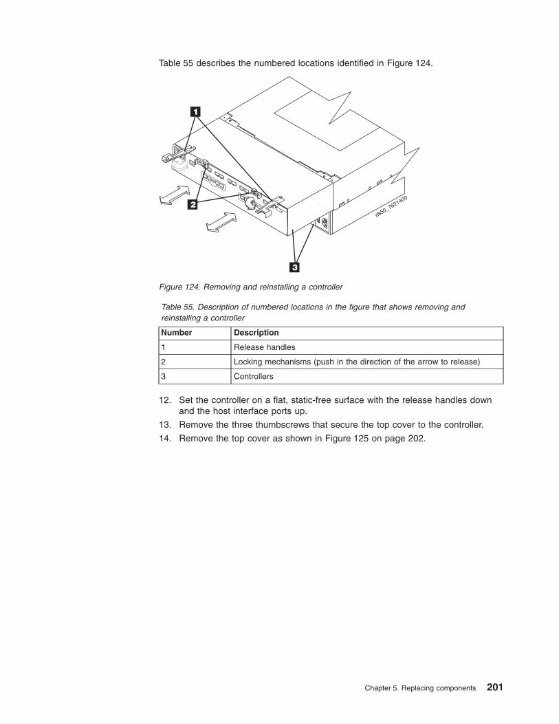
Table 55. Description of numbered locations in the figure that shows removing andreinstalling a controller
Number Description
1 Release handles
2 Locking mechanisms (push in the direction of the arrow to release)
3 Controllers
12. Set the controller on a flat, static-free surface with the release handles downand the host interface ports up.
13. Remove the three thumbscrews that secure the top cover to the controller.
14. Remove the top cover as shown in Figure 125 on page 202.
Table 55 describes the numbered locations identified in Figure 124.
ds50_76214002
3
1
Figure 124. Removing and reinstalling a controller
Chapter 5. Replacing components 201

Table 56. Description of numbered locations in the figure that shows removing a controllercover and replacing a host interface card
Number Description
1 Cover thumbscrews
2 Two host interface cards with alignment slots
3 Host interface card thumbscrews
4 Controller card sockets for connecting the host interface cards
5 Host interface card alignment pins
6 Host interface card port covers
15. Locate the host interface card that you want to replace. See Figure 126 onpage 203, and Table 57 on page 203, which describes the numbered locationsidentified in Figure 126 on page 203.
Table 56 describes the numbered locations identified in Figure 125.
ds50_7620401
2
3
4
5
1
6
Figure 125. Removing controller cover and replacing host interface card
202 IBM System Storage DS5100 or DS5300 Storage Subsystem: Installation, User’s, and Maintenance Guide

Table 57. Description of numbered locations in the figure that shows host interface cardslots on controllers A and B
Number Description
1 Host interface card - slot 1 - controller B
2 Host interface card - slot 2 - controller B
3 Host interface card - slot 1 - controller A
4 Host interface card - slot 2 - controller A
16. Loosen the thumbscrew on the host interface card that secures it to thecontroller card.
17. Gently lift the host interface card to disengage the host interface pins from theconnector on the controller card. Pull away from the front to remove.
Note: The connector is located on the corner of the host interface card next tothe thumbscrew. Note how the card fits against the two guide posts.These guide posts help align the connecting hardware.
18. Using the thumbscrews, remove the host interface card port cover and keep it.
19. Place the host interface card that you removed on a static-free surface.
20. Install the new host interface card by performing the following steps:
a. Using the thumbscrew, remove the blank host interface card port cover.
b. Align the new host interface card with the guide posts.
c. Gently push down on the connector to seat the pins into the connectorsocket.
21. Tighten the thumbscrew to securely fasten the host interface card to thecontroller card. Do not overtighten the thumbscrew.
22. Reinstall the host interface card port cover you removed in step 18 using thethumbscrew. See Figure 125 on page 202 for an illustration of a host interfacecard port cover.
23. Replace the top cover.
24. Make sure that all of the thumbscrews that secure the top cover are tight.
25. Slide the controller all the way into the enclosure. Rotate the release handlesinward to lock the controller into place.
3
1 2
ds5
0_
76
21
70
5
4
Figure 126. Host interface card slots on controllers A and B
Chapter 5. Replacing components 203

26. Reconnect all of the host interface cables to the appropriate host interfaceports.
27. Reconnect all of the drive interface cables from the storage expansionenclosure ESMs to the controller.
Note: Make sure you connect the host interface cables to the appropriate hostinterface ports and the drive interface cables to the appropriate driveinterface ports. Incorrectly cabling host interface cables to driveinterface ports and drive interface cables to host interface ports cancause problems when you restart the controller after inserting it into thechassis.
28. Plug in the power cord to the controller or controllers.
29. Turn on the power switch on the controller or controllers.
30. Look at the LEDs on the controller to verify the controller is rebooting correctly.Figure 127 shows the locations of the LEDs. Table 58 describes the numberedlocations identified in Figure 127.
Table 58. Description of numbered locations in the figure that shows the controller ServiceAction LEDs
Number Description
1 Controller Service Action Allowed LED (Blue)
2 Controller Service Action Required LED (Amber)
3 Numeric Display LED
The LEDs come on and go off intermittently for approximately 60 seconds(possibly longer) and the Numeric Display LED flashes various codes. After theNumeric Display LED displays a number that matches the previously recordedenclosure IDs, you are able to discover the controller through the DS StorageManager software.
After the controller completes the boot process, a number appears in theNumeric Display LED. This number is the controller's enclosure ID, and itshould match the enclosure ID in the Numeric Display LED on the other
123
1 2 3
ds5
0_
76
21
70
1
Figure 127. Controller Service Action LEDs
204 IBM System Storage DS5100 or DS5300 Storage Subsystem: Installation, User’s, and Maintenance Guide

(non-replaced) controller. If the numbers (enclosure IDs) are different, refer toDS5000 Installation, User's, and Maintenance Guide for troubleshootinginformation.
31. Look at the Service Action Required LED on the controller, and look at all ofthe controller enclosure's Service Action Required LEDs. Based on the LEDstatus, perform one of these actions:
v All of the Service Action Required LEDs are off, and the SubsystemManagement window indicates an Optimal status – Go to step 34.
v Any of the controller enclosure’s Service Action Required LEDs is on –Check that the controller has been installed correctly. Reinstall the controllerif necessary. Go to step 32.
32. Open the DS Storage Manager client and ensure that the storage subsystemis optimal. Redistributed LUNs if necessary. If your storage subsystem doesnot have an Optimal status, click the Recovery Guru toolbar button in theSubsystem Management window to determine if any other actions arerequired.
33. Did this action correct the problem?
v Yes – Go to 34.
v No – If the problem has not been resolved, contact IBM Support.
34. Remove the anti-static protection.
35. Check the status of all of the storage expansion enclosures in the storagesubsystem configuration.
36. Does any component have a Needs Attention status?
v Yes – Click the Recovery Guru toolbar button in the SubsystemManagement window, and complete the recovery procedure. If the problemis not resolved, contact IBM Support.
v No – Go to step 37.
37. Use the DS Storage Manager client to create, save, and print a new storagesubsystem profile as well as collect and save all support data.
Replacing a power supply and fan unitThe power supply and fan unit is a component that includes both a 400-W powersupply unit and two fans. The power supply and fan units provide power andcooling for the DS5100 or DS5300. The power supply and fan units are customerreplaceable units (FRUs) and do not require preventive maintenance. Use only thesupported power supply and fan units for your specific storage subsystem.
Each power supply and fan unit has a built-in sensor that detects the followingconditions:
v Over-voltage
v Over-current
v Overheated power supply
If any of these conditions occurs, one or both power supplies will shut down. If thepower remains off after the condition that causes it to go off, make sure that theenvironment is optimal (no overheating has occurred, all electrical outlets areworking, and so on). For more information, see “Restoring power after anunexpected shutdown” on page 160.
Chapter 5. Replacing components 205

The storage subsystem cooling system consists of two fans in each of the twopower supply and fan units. The power supply and fan units circulate air from thefront to the back of the unit.
If both power supply and fan units fail, or if the power supply and fan units cannotmaintain an internal temperature below 70° C (158° F), the power supply and fanunits in the unit will automatically shut down (an over-temperature condition). If thisoccurs, you must cool the unit and restart it. See “Restoring power after anunexpected shutdown” on page 160.
Attention: The fans in the power supply and fan units draw in fresh air and forceout hot air. The power supply and fan units are hot-swappable and redundant;however, if the fans in one power supply and fan unit fail, you must replace theentire failed power supply and fan unit within 48 hours to maintain redundancy andoptimum cooling. Do not remove the failed power supply and fan unit from theDS5100 or DS5300 chassis until you have the replacement power supply and fanunit. When you do remove the failed power supply and fan unit, be sure to installthe second power supply and fan unit within 15 minutes to prevent any overheatingdue to the interruption to the air flow that cools the chassis.
Do not run the storage subsystem without adequate ventilation and cooling,because it might cause damage to the internal components and circuitry.
Before you begin, ensure that you wear an anti-static wrist strap.
Use the following procedure to replace a power supply and fan unit. Each powersupply and fan unit contains a power supply, cooling fan, battery charger, andtemperature sensor. If any of these components fail, you must replace power supplyand fan unit. The power supply, fan, battery charger, and temperature sensor arenot individually replaceable components within the power supply and fan unit.
Statement 8:
CAUTION:Never remove the cover on a power supply and fan unit or any part that hasthe following label attached.
Hazardous voltage, current, and energy levels are present inside anycomponent that has this label attached. There are no serviceable parts insidethese components. If you suspect a problem with one of these parts, contacta service technician.
1. Use the DS Storage Manager client software to print a storage subsystemprofile.
2. Locate the storage subsystem that contains the failed power supply and fanunit by checking the Overall Configuration Needs Attention LED on the front
206 IBM System Storage DS5100 or DS5300 Storage Subsystem: Installation, User’s, and Maintenance Guide
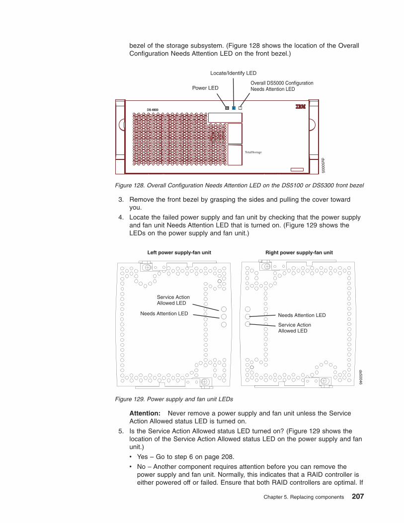
bezel of the storage subsystem. (Figure 128 shows the location of the OverallConfiguration Needs Attention LED on the front bezel.)
3. Remove the front bezel by grasping the sides and pulling the cover towardyou.
4. Locate the failed power supply and fan unit by checking that the power supplyand fan unit Needs Attention LED that is turned on. (Figure 129 shows theLEDs on the power supply and fan unit.)
Attention: Never remove a power supply and fan unit unless the ServiceAction Allowed status LED is turned on.
5. Is the Service Action Allowed status LED turned on? (Figure 129 shows thelocation of the Service Action Allowed status LED on the power supply and fanunit.)
v Yes – Go to step 6 on page 208.
v No – Another component requires attention before you can remove thepower supply and fan unit. Normally, this indicates that a RAID controller iseither powered off or failed. Ensure that both RAID controllers are optimal. If
Power LEDOverall DS5000 ConfigurationNeeds Attention LED
Locate/Identify LED
ds50005
Figure 128. Overall Configuration Needs Attention LED on the DS5100 or DS5300 front bezel
Needs Attention LED
Service ActionAllowed LED
Needs Attention LED
Service ActionAllowed LED
Right power supply-fan unitLeft power supply-fan unit
ds50046
Figure 129. Power supply and fan unit LEDs
Chapter 5. Replacing components 207
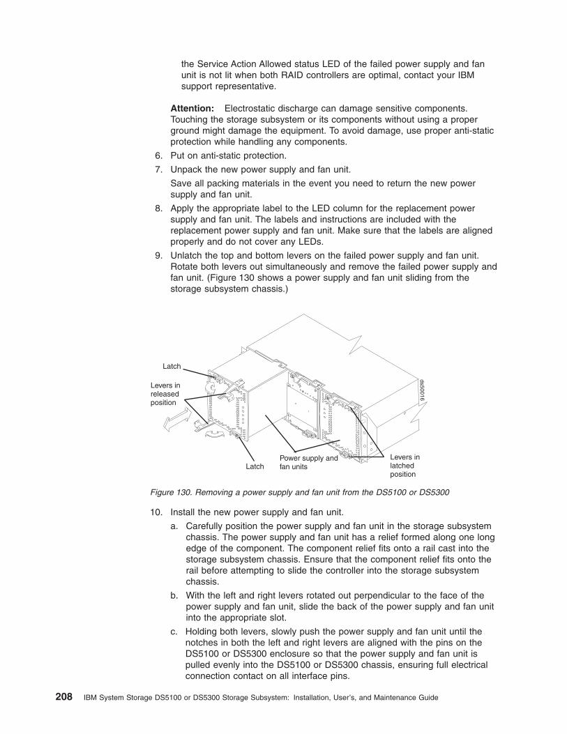
the Service Action Allowed status LED of the failed power supply and fanunit is not lit when both RAID controllers are optimal, contact your IBMsupport representative.
Attention: Electrostatic discharge can damage sensitive components.Touching the storage subsystem or its components without using a properground might damage the equipment. To avoid damage, use proper anti-staticprotection while handling any components.
6. Put on anti-static protection.
7. Unpack the new power supply and fan unit.
Save all packing materials in the event you need to return the new powersupply and fan unit.
8. Apply the appropriate label to the LED column for the replacement powersupply and fan unit. The labels and instructions are included with thereplacement power supply and fan unit. Make sure that the labels are alignedproperly and do not cover any LEDs.
9. Unlatch the top and bottom levers on the failed power supply and fan unit.Rotate both levers out simultaneously and remove the failed power supply andfan unit. (Figure 130 shows a power supply and fan unit sliding from thestorage subsystem chassis.)
10. Install the new power supply and fan unit.
a. Carefully position the power supply and fan unit in the storage subsystemchassis. The power supply and fan unit has a relief formed along one longedge of the component. The component relief fits onto a rail cast into thestorage subsystem chassis. Ensure that the component relief fits onto therail before attempting to slide the controller into the storage subsystemchassis.
b. With the left and right levers rotated out perpendicular to the face of thepower supply and fan unit, slide the back of the power supply and fan unitinto the appropriate slot.
c. Holding both levers, slowly push the power supply and fan unit until thenotches in both the left and right levers are aligned with the pins on theDS5100 or DS5300 enclosure so that the power supply and fan unit ispulled evenly into the DS5100 or DS5300 chassis, ensuring full electricalconnection contact on all interface pins.
Latch
LatchPower supply andfan units
Levers inreleasedposition
Levers inlatchedposition
ds50016
Figure 130. Removing a power supply and fan unit from the DS5100 or DS5300
208 IBM System Storage DS5100 or DS5300 Storage Subsystem: Installation, User’s, and Maintenance Guide
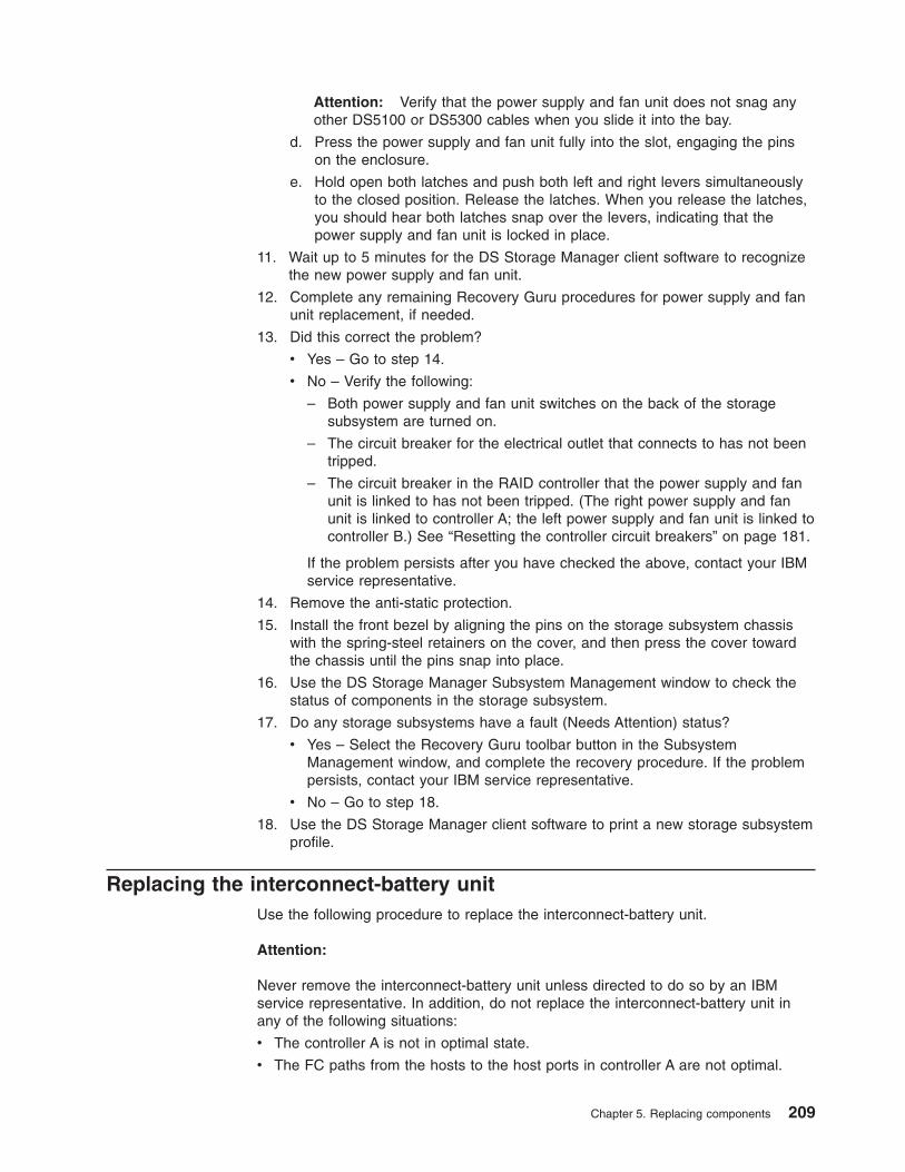
Attention: Verify that the power supply and fan unit does not snag anyother DS5100 or DS5300 cables when you slide it into the bay.
d. Press the power supply and fan unit fully into the slot, engaging the pinson the enclosure.
e. Hold open both latches and push both left and right levers simultaneouslyto the closed position. Release the latches. When you release the latches,you should hear both latches snap over the levers, indicating that thepower supply and fan unit is locked in place.
11. Wait up to 5 minutes for the DS Storage Manager client software to recognizethe new power supply and fan unit.
12. Complete any remaining Recovery Guru procedures for power supply and fanunit replacement, if needed.
13. Did this correct the problem?
v Yes – Go to step 14.
v No – Verify the following:
– Both power supply and fan unit switches on the back of the storagesubsystem are turned on.
– The circuit breaker for the electrical outlet that connects to has not beentripped.
– The circuit breaker in the RAID controller that the power supply and fanunit is linked to has not been tripped. (The right power supply and fanunit is linked to controller A; the left power supply and fan unit is linked tocontroller B.) See “Resetting the controller circuit breakers” on page 181.
If the problem persists after you have checked the above, contact your IBMservice representative.
14. Remove the anti-static protection.
15. Install the front bezel by aligning the pins on the storage subsystem chassiswith the spring-steel retainers on the cover, and then press the cover towardthe chassis until the pins snap into place.
16. Use the DS Storage Manager Subsystem Management window to check thestatus of components in the storage subsystem.
17. Do any storage subsystems have a fault (Needs Attention) status?
v Yes – Select the Recovery Guru toolbar button in the SubsystemManagement window, and complete the recovery procedure. If the problempersists, contact your IBM service representative.
v No – Go to step 18.
18. Use the DS Storage Manager client software to print a new storage subsystemprofile.
Replacing the interconnect-battery unitUse the following procedure to replace the interconnect-battery unit.
Attention:
Never remove the interconnect-battery unit unless directed to do so by an IBMservice representative. In addition, do not replace the interconnect-battery unit inany of the following situations:
v The controller A is not in optimal state.
v The FC paths from the hosts to the host ports in controller A are not optimal.
Chapter 5. Replacing components 209

v The drive paths from controller A to the storage expansion enclosures are notoptimal.
v The right power supply and fan unit is not powered on or not optimal.
The reason not to replace the interconnect-battery unit in any of the abovesituations is because controller A is the designated controller to receive all I/Oswhen the interconnect-battery unit is removed from the storage subsystem. Use theDS Storage Manager client Subsystem Management window and the appropriateSAN monitoring tools to ensure that there are no problems with controller A or withthe connection from the host to controller A.
Also note that LUN Failover between controllers is disabled during this procedurebecause controller B must be placed offline before the interconnect-battery unit isremoved from the storage subsystem. It is best practice to perform theinterconnect-battery unit replacement procedure during off-peak I/O traffic hours.
Before removing the interconnect-battery unit, you must use the DS StorageManager client to place controller B offline. Controller A must display Optimal statusbefore removing the interconnect-battery unit. Do not remove theinterconnect-battery unit if controller A does not display Optimal status.
Electrostatic discharge can damage sensitive components. Touching the storagesubsystem or its components without using a proper ground might damage theequipment. To avoid damage, use proper anti-static protection while handling anycomponents. While you replace the battery unit, make sure that the power supply isnot switched off for more than 15 minutes. If the power supply is off for more than15 minutes, it may result in overheating of the chassis.
1. Locate the failed interconnect-battery unit by checking the OverallConfiguration Needs Attention LED on the front bezel of the storagesubsystem. (Figure 131 shows the location of the Overall Configuration NeedsAttention LED on the front bezel.)
2. Use the DS Storage Manager client to place controller B offline.
Attention: Controller A must display Optimal status before removing theinterconnect-battery unit. Do not remove the interconnect-battery unit ifcontroller A does not display Optimal status.
3. Remove the front bezel by grasping the sides and pulling the cover towardyou.
Power LEDOverall DS5000 ConfigurationNeeds Attention LED
Locate/Identify LED
ds50005
Figure 131. Overall Configuration Needs Attention LED on the DS5100 or DS5300 front bezel
210 IBM System Storage DS5100 or DS5300 Storage Subsystem: Installation, User’s, and Maintenance Guide

Attention: Never remove a power supply and fan unit unless the ServiceAction Allowed status LED is turned on.
4. Is the Service Action Allowed status LED turned on? (Figure 132 shows thelocation of the Service Action Allowed status LED on the interconnect-batteryunit.)
v Yes – Go to step 5.
v No – Make sure that the right power supply and fan unit is connected,powered on, and in optimal state.
If the right power supply and fan unit is connected, powered on, and inoptimal state and Service Action Allowed status LED remains unlit, run theRecovery Guru to determine what other components might require attention.If the Recovery Guru does not indicate any other component problems,contact your IBM support representative.
5. Put on anti-static protection.
6. Unpack the interconnect-battery unit.
Save all packing materials in the event you need to return the newinterconnect-battery unit.
7. Unlatch both the top and bottom levers of the interconnect-battery unit androtate both levers straight out simultaneously to remove the failedinterconnect-battery unit. (Figure 133 on page 212 shows theinterconnect-battery unit sliding from the storage subsystem chassis.)
Service ActionAllowed LED (blue)
ds50049
Overall DS5000 ConfigurationNeeds Attention LED (amber)
Figure 132. Interconnect-battery unit Needs Attention and Service Action Allowed LEDs
Chapter 5. Replacing components 211
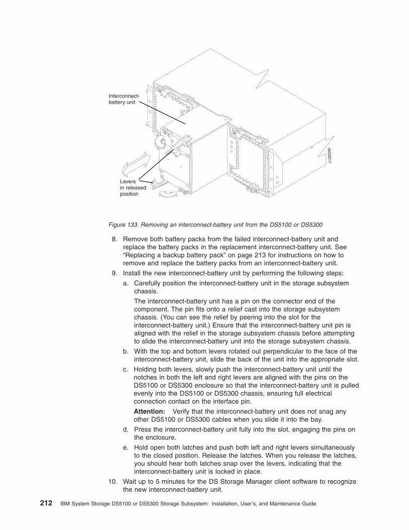
8. Remove both battery packs from the failed interconnect-battery unit andreplace the battery packs in the replacement interconnect-battery unit. See“Replacing a backup battery pack” on page 213 for instructions on how toremove and replace the battery packs from an interconnect-battery unit.
9. Install the new interconnect-battery unit by performing the following steps:
a. Carefully position the interconnect-battery unit in the storage subsystemchassis.
The interconnect-battery unit has a pin on the connector end of thecomponent. The pin fits onto a relief cast into the storage subsystemchassis. (You can see the relief by peering into the slot for theinterconnect-battery unit.) Ensure that the interconnect-battery unit pin isaligned with the relief in the storage subsystem chassis before attemptingto slide the interconnect-battery unit into the storage subsystem chassis.
b. With the top and bottom levers rotated out perpendicular to the face of theinterconnect-battery unit, slide the back of the unit into the appropriate slot.
c. Holding both levers, slowly push the interconnect-battery unit until thenotches in both the left and right levers are aligned with the pins on theDS5100 or DS5300 enclosure so that the interconnect-battery unit is pulledevenly into the DS5100 or DS5300 chassis, ensuring full electricalconnection contact on the interface pin.
Attention: Verify that the interconnect-battery unit does not snag anyother DS5100 or DS5300 cables when you slide it into the bay.
d. Press the interconnect-battery unit fully into the slot, engaging the pins onthe enclosure.
e. Hold open both latches and push both left and right levers simultaneouslyto the closed position. Release the latches. When you release the latches,you should hear both latches snap over the levers, indicating that theinterconnect-battery unit is locked in place.
10. Wait up to 5 minutes for the DS Storage Manager client software to recognizethe new interconnect-battery unit.
Leversin releasedposition
Interconnect-battery unit
ds50017
Figure 133. Removing an interconnect-battery unit from the DS5100 or DS5300
212 IBM System Storage DS5100 or DS5300 Storage Subsystem: Installation, User’s, and Maintenance Guide

11. Use the DS Storage Manager client to place controller B online.
12. Complete any remaining Recovery Guru procedures for interconnect-batteryunit replacement, if needed.
13. Did this correct the problem?
v Yes – Go to step 14.
v No – If the problem has not been fixed, contact your IBM servicerepresentative.
14. Remove the anti-static protection.
15. Install the front bezel by aligning the pins on the storage subsystem chassiswith the spring-steel retainers on the cover and then press the cover towardthe chassis until the pins snap into place.
16. Use the Subsystem Management window to check the status of allcomponents in the storage subsystem.
17. Do any storage subsystems have a fault (Needs Attention) status?
v Yes – Select the Recovery Guru toolbar button in the DS Storage ManagerSubsystem Management window, and complete the recovery procedure. Ifthe problem persists, contact your IBM support representative.
v No – Go to step 18.
18. Use the DS Storage Manager client software to print a new storage subsystemprofile.
Replacing a backup battery packUse the following procedure if the DS Storage Manager client instructs you toreplace the battery because the current battery has failed. You can also use the DSStorage Manager client to check the status of the battery. Because write-caching isdisabled when either one of the backup battery packs fail, it is best practice toreplace the failed battery pack as soon as possible to minimize any impact due tothe disabling of the write-caching function.
Replace only the battery pack that is indicated as failed by the LEDs. You do notneed to replace both battery packs when the Battery LEDs indicate that only onebattery pack has failed.
Note: Unlike the batteries for other DS Storage Subsystems, the StorageSubsystem battery packs do not have set expiration dates. Do not replacethese batteries after a certain usage period.
Attention: When you handle static-sensitive devices, take precautions to avoiddamage from static electricity. For details about handling static-sensitive devices,see “Handling static-sensitive devices” on page 189.
Before you begin, ensure that you wear an anti-static wrist strap.
Use the following procedure to replace a backup battery pack in theinterconnect-battery unit:
1. Use the DS Storage Manager client software to print a storage subsystemprofile.
2. Locate the storage subsystem that contains the interconnect-battery unit withthe failed battery by checking the Overall Configuration Needs Attention LEDon the front bezel of the storage subsystem. (Figure 134 on page 214 showsthe location of the Overall Configuration Needs Attention LED on the front
Chapter 5. Replacing components 213
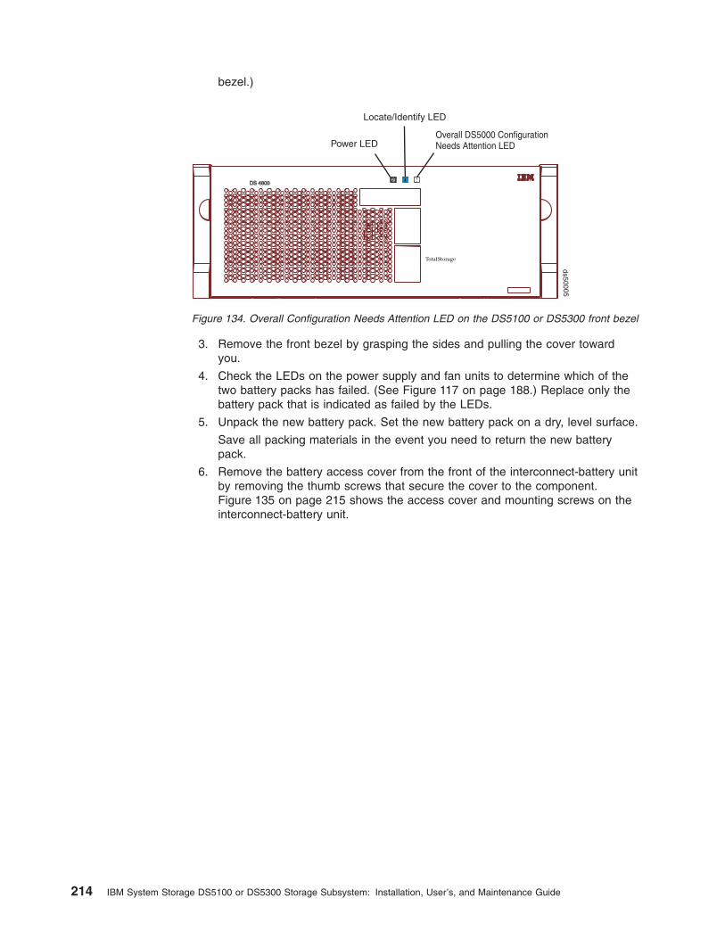
bezel.)
3. Remove the front bezel by grasping the sides and pulling the cover towardyou.
4. Check the LEDs on the power supply and fan units to determine which of thetwo battery packs has failed. (See Figure 117 on page 188.) Replace only thebattery pack that is indicated as failed by the LEDs.
5. Unpack the new battery pack. Set the new battery pack on a dry, level surface.
Save all packing materials in the event you need to return the new batterypack.
6. Remove the battery access cover from the front of the interconnect-battery unitby removing the thumb screws that secure the cover to the component.Figure 135 on page 215 shows the access cover and mounting screws on theinterconnect-battery unit.
Power LEDOverall DS5000 ConfigurationNeeds Attention LED
Locate/Identify LED
ds50005
Figure 134. Overall Configuration Needs Attention LED on the DS5100 or DS5300 front bezel
214 IBM System Storage DS5100 or DS5300 Storage Subsystem: Installation, User’s, and Maintenance Guide

7. Remove the failed battery pack by sliding it out of the interconnect-battery unit.
Note: There are two battery packs in the interconnect-battery unit. The rightand left Battery Needs Attention LEDs on the interconnect-battery unitcorrespond to each of the two battery packs. Be sure to remove thefailed battery, as indicated by the lit amber Battery Needs AttentionLED.
The battery pack is mounted to a sheet metal bracket. The sheet metal brackethas a flange formed on the end of the bracket closest to the access in theinterconnect-battery unit. Grasp the flange to slide the battery pack from theinterconnect-battery unit.
Accesscover
Thumbscrews
ds48050
Figure 135. Battery access cover on the interconnect-battery unit
Chapter 5. Replacing components 215

CAUTION:This product contains a sealed Lithium Ion battery. Discharged Lithiumand Lithium Ion batteries are currently designated to be disposed of innormal trash. However, users should contact their municipal wastedisposal facility prior to discarding any used battery in normal trash.Alternatively, IBM recommends users may return Lithium, Lithium Ionand Lithium Ion battery packs to IBM for recycling.
In the United States, IBM has established a collection process for reuse,recycling, or proper disposal of used IBM Lithium, Lithium Ion andLithium Ion battery packs. For information on proper disposal of thesebatteries, please contact IBM at 1-800-426-4333. Please have the IBM partnumber listed on the battery available prior to your call.
For information on disposal of sealed Lithium Ion batteries outside theUnited States, go to http://www.ibm.com/ibm/environment/products/batteryrecycle.shtml or contact your local waste disposal facility.
8. Install the replacement battery pack. Carefully position the battery pack toensure that the battery pack will slide correctly into the interconnect-batteryunit. The flat side of the battery pack should face towards the outside of thechassis. Make sure that the battery bracket slides properly into the slots for thebattery. Slide the battery pack into the interconnect-battery unit. Push thebattery pack firmly into the interconnect-battery unit to ensure that the batterypack completely engages with the connectors in the interconnect-battery unit.
9. Reinstall the battery access cover onto the front of the interconnect-batteryunit.
10. Once you have replaced the battery pack, you must reset the battery agethrough the DS Storage Manager client, by performing these three steps:
v First, you must select the Controller enclosure components icon in thePhysical View of the Storage Manager client. The Controller enclosurecomponents dialog will be displayed.
v Next, you must select the Batteries icon, and then select Reset. You will beasked to Confirm Reset. Select Yes to confirm that you want to reset thebattery age.
v Now, the battery age clock is reset to 0.
11. Remove the anti-static protection.
12. Install the front bezel by aligning the pins on the storage subsystem chassiswith the spring-steel retainers on the cover and then press the cover towardthe chassis until the pins snap into place.
13. Use the Subsystem Management window to check the status of allcomponents in the storage subsystem.
14. Do any storage subsystems have a fault (Needs Attention) status?
v Yes – Select the Recovery Guru toolbar button in the DS Storage ManagerSubsystem Management window, and complete the recovery procedure. Ifthe problem persists, contact your IBM service representative.
v No – Go to step 15.
15. Use the DS Storage Manager client software to print a new storage subsystemprofile.
Note: Note that it might take from 15 minutes to a few hours for a new batteryto become fully charged. The DS Storage Manager client will show thebattery as charging until it is fully charged. Controller caching isautomatically disabled until the new battery becomes fully charged.
216 IBM System Storage DS5100 or DS5300 Storage Subsystem: Installation, User’s, and Maintenance Guide
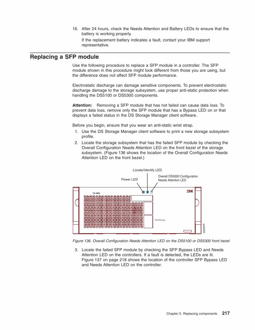
16. After 24 hours, check the Needs Attention and Battery LEDs to ensure that thebattery is working properly.
If the replacement battery indicates a fault, contact your IBM supportrepresentative.
Replacing a SFP moduleUse the following procedure to replace a SFP module in a controller. The SFPmodule shown in this procedure might look different from those you are using, butthe difference does not affect SFP module performance.
Electrostatic discharge can damage sensitive components. To prevent electrostaticdischarge damage to the storage subsystem, use proper anti-static protection whenhandling the DS5100 or DS5300 components.
Attention: Removing a SFP module that has not failed can cause data loss. Toprevent data loss, remove only the SFP module that has a Bypass LED on or thatdisplays a failed status in the DS Storage Manager client software.
Before you begin, ensure that you wear an anti-static wrist strap.
1. Use the DS Storage Manager client software to print a new storage subsystemprofile.
2. Locate the storage subsystem that has the failed SFP module by checking theOverall Configuration Needs Attention LED on the front bezel of the storagesubsystem. (Figure 136 shows the location of the Overall Configuration NeedsAttention LED on the front bezel.)
3. Locate the failed SFP module by checking the SFP Bypass LED and NeedsAttention LED on the controllers. If a fault is detected, the LEDs are lit.Figure 137 on page 218 shows the location of the controller SFP Bypass LEDand Needs Attention LED on the controller.
Power LEDOverall DS5000 ConfigurationNeeds Attention LED
Locate/Identify LED
ds50005
Figure 136. Overall Configuration Needs Attention LED on the DS5100 or DS5300 front bezel
Chapter 5. Replacing components 217

4. Put on anti-static protection.
5. Unpack the new SFP module. Verify that it is the same type of module you arereplacing. Save all packing materials in the event you might need to return thenew SFP module.
Attention: Handle and install fiber-optic cables properly to avoid degradedperformance or loss of communications with devices. For specific handlingguidelines, see “Handling fibre-optic cables” on page 50.
6. Disconnect the interface cable from the SFP module. (Figure 138 shows theSFP module, interface cable, and the rear of a controller.)
7. Remove the failed SFP module from the controller.
8. Install the new SFP module into the controller.
9. Reconnect the interface cable.
Controller A
ds50051
Controller B
SFP Bypass LEDs
SFP Bypass LEDs
Figure 137. Needs Attention and SFP Model Bypass LEDs
ds50031
Figure 138. Replacing a SFP or SFP+ module
218 IBM System Storage DS5100 or DS5300 Storage Subsystem: Installation, User’s, and Maintenance Guide

10. Check the Bypass and Needs Attention LEDs for the new SFP module.
Based on the status of the Bypass and Needs Attention LEDs, choose one ofthe following steps:
v Bypass LED or Needs Attention LED is illuminated – The SFP module andcables might be installed incorrectly, or the cable might not be securelyconnected. Reinstall the SFP module and cable, check the cableconnection, and then go to step 11.
v Bypass LED and Needs Attention LED are off – Go to step 12.
11. Is the problem corrected?
v Yes – Go to step 12.
v No – Contact your IBM support representative.
12. Remove the anti-static protection.
13. Use the DS Storage Manager Subsystem Management window to check thestatus of all components in the storage subsystem.
14. Do any storage subsystems have a Needs Attention (Needs Attention) status?
v Yes – Select the Recovery Guru toolbar button in the SubsystemManagement window and complete the recovery procedure. If the problempersists, contact your IBM service representative.
v No – Go to step 15.
15. Use the DS Storage Manager client software to print a new storage subsystemprofile.
Replacing a SFP+ moduleBefore you begin, ensure that you wear an anti-static wrist strap.
Use the following procedure to replace a SFP+ module in a controller.
Note: A SFP+ module looks the same as a SFP module, so the module type mustbe identified by the FRU part number. Ensure that the FRU part number onthe new SFP+ module is correct for the failed 10GbE SFP+ module that is tobe replaced.
Electrostatic discharge can damage sensitive components. To prevent electrostaticdischarge damage to the storage subsystem, use proper anti-static protection whenhandling the DS5100 or DS5300 components.
Attention: Removing a SFP+ module that has not failed can cause data loss. Toprevent data loss, remove only the SFP+ module that has a port Link LED that isunlit, or that displays a failed status in the DS Storage Manager client software.
1. Use the DS Storage Manager client software to print a new storage subsystemprofile.
2. Locate the storage subsystem that has the failed SFP+ module by checkingthe Overall Configuration Needs Attention LED on the front bezel of thestorage subsystem. (Figure 136 on page 217 shows the location of the OverallConfiguration Needs Attention LED on the front bezel.)
3. Locate the failed SFP+ module by checking the SFP+ port Link LED on the 10Gbps iSCSI Host Interface Card and the Needs Attention LED on thecontrollers. If a fault is detected, the SFP+ port Link LED is unlit and theNeeds Attention LED is lit.
Chapter 5. Replacing components 219
Note: Before replacing the SFP+ module in the 10 GbE HIC port, it is bestpractice to confirm that the SFP+ module is bad by analyzing it with anoptical loopback. With an optical loopback inserted, observe the statusof the SFP+ port Link LED and perform the following checks:
v If the SFP+ port Link LED is unlit, the 10 Gbps SFP+ module is badand should be replaced.
v If the SFP+ port Link LED is lit, verify that the port is connected to anactive 10 Gb Ethernet switch port, and that the problem is not causedby another component or connection in the link. For example, verifythe following conditions:
– The cable is plugged in at the switch port.
– The SFP+ module is correctly inserted in the switch port.
– The switch port is enabled.
Figure 137 on page 218 shows the location of the controller SFP+ port LinkLED and Needs Attention LED on the controller.
4. Unpack the new SFP+ module. Verify that it is the same type of module youare replacing by comparing the Part Number information on the labels that areattached to the new and failed SFP+ modules. Save all packing materials inthe event you might need to return the new SFP+ module.
Attention: Handle and install fiber-optic cables properly to avoid degradedperformance or loss of communications with devices. For specific handlingguidelines, see “Handling fibre-optic cables” on page 50.
5. Disconnect the interface cable from the SFP+ module. (Figure 138 on page218 shows the SFP+ module, interface cable, and the rear of a controller.)
6. Remove the failed SFP+ module from the controller.
7. Install the new SFP+ module into the controller.
8. Reconnect the interface cable.
9. Check the Link and Needs Attention LEDs for the new SFP+ module and thecontroller.
Based on the status of the Link and Needs Attention LEDs, choose one of thefollowing steps:
a. 10 GB HIC port link LED is unlit or Needs Attention LED is lit – The SFP+module and cables might be installed incorrectly, the cable might not besecurely connected, or the cable is faulty. Reinstall the SFP+ module andwith an optical loopback inserted, observe the status of the 10 GB HIC portlink LED and choose one of the following steps:
v If the 10 GB HIC port link LED is unlit, the new SFP+ module might notbe the correct type, or is faulty. Check and order the new SFP+ moduleas appropriate.
v If the 10 GB HIC port link LED is lit, another component in the link isfaulty. Check the cable connection and the switch port status of theSFP+ module, then go to step 10.
b. 10 GB HIC Port Link LED is lit and Needs Attention LED is unlit – Go tostep 11.
10. Is the problem corrected?
v Yes – Go to step 11.
v No – Contact your IBM support representative.
11. Remove the anti-static protection.
12. Use the DS Storage Manager Subsystem Management window to check thestatus of all components in the storage subsystem.
220 IBM System Storage DS5100 or DS5300 Storage Subsystem: Installation, User’s, and Maintenance Guide

13. Do any storage subsystems have a Needs Attention (Needs Attention) status?
v Yes – Select the Recovery Guru toolbar button in the SubsystemManagement window and complete the recovery procedure. If the problempersists, contact your IBM service representative.
v No – Go to step 14.
14. Use the DS Storage Manager client software to print a new storage subsystemprofile.
Installing SFPs and fiber-optic cablesEach RAID controller unit has single-ported host channels and dual-ported drivechannels. SFPs are inserted into the ports, and then fibre-channel cables areconnected to the SFPs.
For information on installing SFPs and fiber-optic cables, see “Working with SFPs,SFP+s, and fiber-optic cables” on page 49.
Removing and disposing of the lithium batteriesWhen you disassemble the storage subsystem for disposal, use the information inthis section to locate, remove, and dispose of the lithium batteries that are on thesystem boards in Controller A and Controller B.
Chapter 5. Replacing components 221

Statement 2:
CAUTION:When replacing the lithium battery, use only an equivalent type batteryrecommended by the manufacturer. If your system has a module containing alithium battery, replace it only with the same module type made by the samemanufacturer. The battery contains lithium and can explode if not properlyused, handled, or disposed of.
Do not:v Throw or immerse into waterv Heat to more than 100°C (212°F)v Repair or disassemble
Dispose of the battery as required by local ordinances or regulations.
Before you begin, ensure that you wear an anti-static wrist strap.
To remove the batteries for disposal, complete the following steps:
1. Locate the battery compartment on the system board in Controller A.
Notes:
a. The top of the battery compartment is labeled “Li”, and the compartment islocated near the end of the controller system board with the external hostconnectors.
b. If a Fibre channel or iSCSI host interface daughter card is installed on thecontroller, you must remove the card to gain access to the batterycompartment.
2. Insert the flat blade of a small screwdriver into the slot on thebattery-compartment cover.
Slot
3. Move the screwdriver as shown in the illustration until the cover is released fromthe battery-compartment base.
222 IBM System Storage DS5100 or DS5300 Storage Subsystem: Installation, User’s, and Maintenance Guide
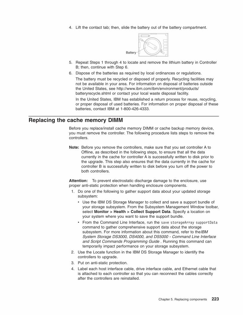
4. Lift the contact tab; then, slide the battery out of the battery compartment.
Battery
5. Repeat Steps 1 through 4 to locate and remove the lithium battery in ControllerB; then, continue with Step 6.
6. Dispose of the batteries as required by local ordinances or regulations.
The battery must be recycled or disposed of properly. Recycling facilities maynot be available in your area. For information on disposal of batteries outsidethe United States, see http://www.ibm.com/ibm/environment/products/batteryrecycle.shtml or contact your local waste disposal facility.
In the United States, IBM has established a return process for reuse, recycling,or proper disposal of used batteries. For information on proper disposal of thesebatteries, contact IBM at 1-800-426-4333.
Replacing the cache memory DIMMBefore you replace/install cache memory DIMM or cache backup memory device,you must remove the controller. The following procedure lists steps to remove thecontrollers.
Note: Before you remove the controllers, make sure that you set controller A toOffline, as described in the following steps, to ensure that all the datacurrently in the cache for controller A is successfully written to disk prior tothe upgrade. This step also ensures that the data currently in the cache forcontroller B is successfully written to disk before you turn off the power toboth controllers.
Attention: To prevent electrostatic discharge damage to the enclosure, useproper anti-static protection when handling enclosure components.
1. Do one of the following to gather support data about your updated storagesubsystem:
v Use the IBM DS Storage Manager to collect and save a support bundle ofyour storage subsystem. From the Subsystem Management Window toolbar,select Monitor > Health > Collect Support Data. Specify a location onyour system where you want to save the support bundle.
v From the Command Line Interface, run the save storageArray supportDatacommand to gather comprehensive support data about the storagesubsystem. For more information about this command, refer to theIBMSystem Storage DS3000, DS4000, and DS5000 - Command Line Interfaceand Script Commands Programming Guide . Running this command cantemporarily impact performance on your storage subsystem.
2. Use the Locate function in the IBM DS Storage Manager to identify thecontrollers to upgrade.
3. Put on anti-static protection.
4. Label each host interface cable, drive interface cable, and Ethernet cable thatis attached to each controller so that you can reconnect the cables correctlyafter the controllers are reinstalled.
Chapter 5. Replacing components 223

Attention: To prevent degraded performance, do not twist, fold, pinch, orstep on the fiber-optic cables. Do not bend the fiber-optic cables tighter than a5-cm (2-in.) radius.
5. Stop all host I/O operations.
6. Do one of the following to take controller A offline.
v From the Hardware pane in the Subsystem Management Window, right-clickthe picture of the controller you want to take offline, and then selectAdvanced > Place > Offline.
v From the Command Line Interface, run the following command:smCLI <DNS-network-name-or-IP-address> -c “set controller [(a | b)]availability=offline”
This command ensures that all the data currently in cache on both controllersis successfully written to disk prior to the upgrade and ensures that no data isstored on the cache backup memory devices.
Attention: Wait for the blue Controller Service Action Allowed LED oncontroller A to come on before you turn off the power to either controller;otherwise, possible data loss or corruption might occur.
7. Wait for the Controller Service Action Allowed LED to come on.
8. Turn off the Power switch on both of the controllers.
9. Wait until all LEDs and seven-segment display activity on the rear of thecontroller enclosure stop, and then unplug the power cords from bothcontrollers, and set the power cords aside.
10. Disconnect all of the following cables from both controllers.
v Host interface cables
v Drive interface cables
v Ethernet cables
11. Remove both controllers from the controller enclosure.
a. Unlock and rotate the release handles out, to release the controller.
b. Using the release handles and your hands, pull the controller out of thecontroller enclosure.
c. Set the controller on a flat, static-free surface with the thumbscrews thatsecure the top cover facing up.
224 IBM System Storage DS5100 or DS5300 Storage Subsystem: Installation, User’s, and Maintenance Guide
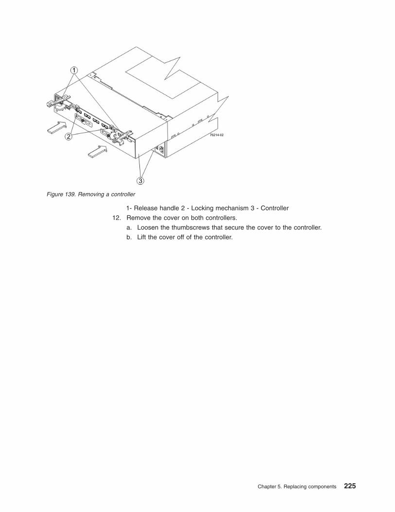
1- Release handle 2 - Locking mechanism 3 - Controller
12. Remove the cover on both controllers.
a. Loosen the thumbscrews that secure the cover to the controller.
b. Lift the cover off of the controller.
Figure 139. Removing a controller
Chapter 5. Replacing components 225
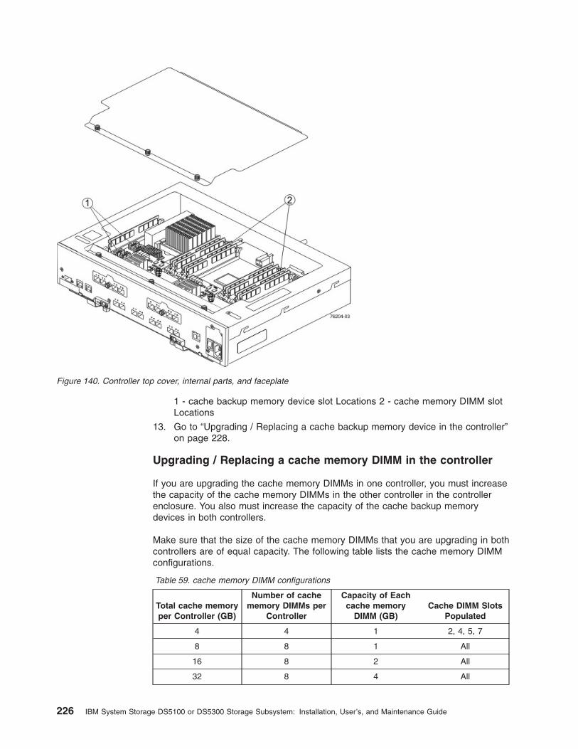
1 - cache backup memory device slot Locations 2 - cache memory DIMM slotLocations
13. Go to “Upgrading / Replacing a cache backup memory device in the controller”on page 228.
Upgrading / Replacing a cache memory DIMM in the controller
If you are upgrading the cache memory DIMMs in one controller, you must increasethe capacity of the cache memory DIMMs in the other controller in the controllerenclosure. You also must increase the capacity of the cache backup memorydevices in both controllers.
Make sure that the size of the cache memory DIMMs that you are upgrading in bothcontrollers are of equal capacity. The following table lists the cache memory DIMMconfigurations.
Table 59. cache memory DIMM configurations
Total cache memoryper Controller (GB)
Number of cachememory DIMMs per
Controller
Capacity of Eachcache memory
DIMM (GB)Cache DIMM Slots
Populated
4 4 1 2, 4, 5, 7
8 8 1 All
16 8 2 All
32 8 4 All
Figure 140. Controller top cover, internal parts, and faceplate
226 IBM System Storage DS5100 or DS5300 Storage Subsystem: Installation, User’s, and Maintenance Guide

1. Locate the cache memory DIMMs that you want to upgrade, or identify thelocation to add the new cache memory DIMMs.
2. If you are adding an cache memory DIMM go to step 4. Go to the next step ifyou are upgrading a cache memory DIMM.
3. Remove the cache memory DIMMs from their slots on the controller card .
a. Pull back on each ejector handle to disengage the cache memory DIMMpins from the slot on the controller card.
b. Lift the cache memory DIMM out of the slot.
c. Place the cache memory DIMM that you removed on an a flat, static-freesurface.
1 - cache memory DIMM 2 - Handles
4. Install the new cache memory DIMM.
a. Align the new cache memory DIMM in the slot.
b. Gently push down on the cache memory DIMM to seat the pins into the slot.
Figure 141. Numbers indicate cache memory DIMM locations
Figure 142. Removing a cache memory DIMM
Chapter 5. Replacing components 227
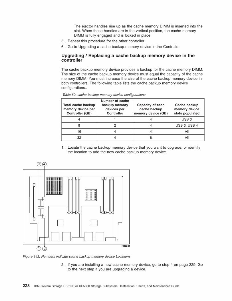
The ejector handles rise up as the cache memory DIMM is inserted into theslot. When these handles are in the vertical position, the cache memoryDIMM is fully engaged and is locked in place.
5. Repeat this procedure for the other controller.
6. Go to Upgrading a cache backup memory device in the Controller.
Upgrading / Replacing a cache backup memory device in thecontroller
The cache backup memory device provides a backup for the cache memory DIMM.The size of the cache backup memory device must equal the capacity of the cachememory DIMM. You must increase the size of the cache backup memory device inboth controllers. The following table lists the cache backup memory deviceconfigurations..
Table 60. cache backup memory device configurations
Total cache backupmemory device per
Controller (GB)
Number of cachebackup memory
devices perController
Capacity of eachcache backup
memory device (GB)
Cache backupmemory deviceslots populated
4 1 4 USB 3
8 2 4 USB 3, USB 4
16 4 4 All
32 4 8 All
1. Locate the cache backup memory device that you want to upgrade, or identifythe location to add the new cache backup memory device.
2. If you are installing a new cache memory device, go to step 4 on page 229. Goto the next step if you are upgrading a device.
Figure 143. Numbers indicate cache backup memory device Locations
228 IBM System Storage DS5100 or DS5300 Storage Subsystem: Installation, User’s, and Maintenance Guide

3. Remove the cache backup memory device from the connector on the controllercard.
a. Gently pull back on the latch that secures one edge of the cache backupmemory device to the connector on the controller card.
b. Lift the cache backup memory device from the connector.
4. Install the new cache backup memory device.
a. Carefully align the cache backup memory device with the connector on thecontroller card so that the pins do not bend when you install the cachebackup memory device.
b. Install the cache backup memory device into an empty socket location bygently pressing down on the cache backup memory device until it snaps intoplace.
5. Repeat this procedure for the other controller and reinstall the controller in theenclosure.
Reinstalling the controller in the enclosure1. Reinstall the top covers on both controllers, and tighten all of the thumbscrews
that secure the top cover.
2. Slide both controllers all of the way into the controller enclosure. Rotate therelease handles in, to lock each controller into place.
3. Reconnect the following cables to the appropriate ports on both controllers.
v Ethernet cables
v Host interface cables
v Drive interface cables
4. Plug in the power cords to both of the controllers.
5. Turn on the Power switches on both of the controllers. Controller B comes upin Write-Through mode. Controller A comes up in an Offline state.
6. Bring controller A online. In the Subsystem Management Window, right-clickthe controller, and then select Advanced > Place > Online, or use thefollowing CLI command.set controller [a] availability=online;
7. Check the LEDs on the controller to ensure that the controllers are rebootingcorrectly.
1. Controller Service Action Allowed LED (Blue) 2. Controller Service Action Required LED (Amber)Figure 144. Controller Service Action LEDs
Chapter 5. Replacing components 229

The LEDs come on and go off intermittently for approximately 60 seconds(possibly longer).
The seven-segment display shows the sequenceOS+ Sd+ blank- to indicatethat the controller is performing Start-of-day (SOD) processing. After thecontroller successfully completes rebooting, the seven-segment display showsthe enclosure ID matching the seven-segment display on the second controller.After this time, you can discover the controller with the new battery by usingthe IBM DS Storage Manager.
8. All of the Service Action Required LEDs are off, and the SubsystemManagement Window indicates an Optimal status, go to step 10. Else go tothe next step.
9. Perform one of the following actions (based on the Recovery Guru display):
v The Recovery Guru displays the following message:REC_CACHE_BACKUP_DEVICE_INSUFFICIENT_CAPACITY – Thecontrollers might require an additional power cycle to initialize the newcache backup memory devices. Turn off the Power switches on bothcontrollers. Wait until all LED and seven-segment display activity stop, andthen turn on the Power switches to both controllers.
v The Recovery Guru does not display an insufficient capacity message –Check that the controller has been installed correctly. Reinstall the controllerif necessary.
If the problem is still not solved, contact IBM Technical Support.
10. Using the LEDs and the IBM DS Storage Manager, check the status of theenclosures in the storage subsystem.
11. If any component has a Needs Attention status, Click Recovery Guru in theSubsystem management Window, and complete the recovery procedure. If theproblem is not resolved, contact your Technical Support representative.
12. Remove the anti-static protection.
13. Gather support data about your storage subsystem by using one of thesemethods:
v Use the IBM DS Storage Manager to collect and save a support bundle ofyour storage subsystem. From the Subsystem management window, selectMonitor > Health > Collect Support Data. Then name and specify alocation on your system where you want to store the support bundle.
v Use the command line interface (CLI) to run the save storageArraysupportData command to gather comprehensive support data about thestorage subsystem. For more information about this command, refer to theIBM System Storage DS3000, DS4000, and DS5000 - Command LineInterface and Script Commands Programming Guide. Running thiscommand can temporarily impact performance on your storage subsystem.
230 IBM System Storage DS5100 or DS5300 Storage Subsystem: Installation, User’s, and Maintenance Guide
Chapter 6. Hardware maintenance
This chapter contains information to help you solve some of the simpler problemsthat you might have with your storage subsystem. It contains the problem indicatorsand error messages along with suggested actions to take to resolve the problem.
For instructions on how to obtain service and technical assistance for your storagesubsystem and other IBM products, see “Getting information, help, and service” onpage xxvii.
General checkoutUse the status LEDs, Symptom-to-FRU index, and the DS Storage Manager clientsoftware to diagnose problems. See “Solving problems.”
To diagnose a cluster system, use the cluster problem determination procedure inthe IBM System Storage Problem Determination Guide.
Note: If power was just applied to the storage subsystem, the green and amberLEDs might turn on and off intermittently. Wait up to five minutes for thestorage subsystem to finish powering up before you begin to check for faults.
Using the diagnostic hardwareThe DS5100 or DS5300 comes with an LC wrap-plug adapter and LC-LC coupler.The wrap-plug adapter and LC-LC coupler are used to perform the loopback testand to identify fibre path problems. See the IBM System Storage ProblemDetermination Guide for more information.
The loopback test and the sendEcho test are described in the IBM System StorageProblem Determination Guide. In the IBM System Storage SAN Integration Serverconfiguration, a loopback adapter (P/N 17P6918) is included to identify pathproblems on the drive loop when using fibre channel 1.2 m copper cable (P/N18P5237).
Solving problemsAlways use the DS Storage Manager client to diagnose storage subsystemproblems and component failures and to find solutions to problems that havedefinite symptoms.
You can use the symptom-to-FRU index (Table 61 on page 232) as a guide fortroubleshooting problems in addition to the DS Storage Manager Recovery Guru inthe Subsystem Management window. Do not depend solely on Table 61 on page232 for FRU replacement decision.
Attention: Do not remove any power supply and fan units, controllers, orinterconnect-battery units from the storage subsystem unless the Service ActionAllowed LED for the component is lit. Always use the appropriate procedure inChapter 5, “Replacing components,” on page 189 to prevent an inadvertentshutdown of the storage subsystem as a result of removing the storage subsystemcomponents in the wrong sequence.
© Copyright IBM Corp. 2008, 2012 231

Table 61. Symptom-to-FRU index
Problemindicator Component Possible cause Possible solutions
Amber NeedsAttention LED onAmber
RAID controllerNeeds AttentionLED
RAID controller offline If you have placed the controller offline, use theDS Storage Manager client software to place itonline.
If one controller has been placed offline by theother controller, contact IBM support. (This is thecase if you use the DS Storage Manager clientsoftware to make repeated attempts to bring anoffline controller online, but the controller keepsreverting back to an offline state.)
RAID controller failure If the RAID controller Needs Attention LED is onand the Service Action Allowed LED for that RAIDcontroller is lit, replace the RAID controller.
If the Service Action Allowed LED for the RAIDcontroller is not lit, perform additional diagnosticsto identify other component failures. Replace theother failed components before replacing theRAID controller.
Drive bypassLED
Fibre-channel cable is notattached to the storageexpansion enclosure.
Connect the fibre-channel cable to the enclosureport; check other connections.
No incoming signaldetected.
Reattach the SFPs and fibre-channel cables.
Verify that the fibre channel cables are in goodcondition. For specific handling guidelines, see“Handling fibre-optic cables” on page 50.
Verify the SFPs are working properly. Use thewrap-plug coupler kit that ships with the storagesubsystem and the wrap-plug instructions in theProblem Determination Guide.
Replace input and output SFPs or cables asnecessary.
OverallConfigurationNeeds AttentionLED (located oninterconnect-battery unit)
General system error Indicates that a Needs Attention LED somewherein the storage subsystem configuration, includingall attached storage expansion enclosures, hasturned on. (Check for amber LEDs on componentsas well as all attached storage expansionenclosures.) Use the DS Storage Managersoftware to diagnose server problems.
Variouscomponents
Multiple component failures Do not randomly replace components in thestorage subsystem. This might result in asubsystem shutdown, causing a loss of dataavailability. Use the DS Storage Manager clientprogram to identify the failed components. Identifyand replace the failed power supply and fan unitcomponents first before fixing any other failedcomponents.
232 IBM System Storage DS5100 or DS5300 Storage Subsystem: Installation, User’s, and Maintenance Guide

Table 61. Symptom-to-FRU index (continued)
Problemindicator Component Possible cause Possible solutions
All green LEDsoff
All FRUs Subsystem power is off. Check that all power cords are plugged in and allpower switches are on. If applicable, check thatthe main circuit breakers for the rack cabinet areturned on.
AC power failure Check the main circuit breaker and ac outlet.
Both power supply and fanunits have failed.
Replace the power supply and fan units.
Both controller circuitbreakers have tripped.
Reset the controller circuit breakers.
Amber LED ison, green LED isoff, blue LED isoff, and OverallStorageSubsystemNeeds AttentionLED is on
Power supplyand fan unit
v Amber NeedsAttention LEDon
v Blue ServiceAction AllowedLED off
v Green PowerLED off
v Power switch on a powersupply and fan unit isturned off.
v An electrical outlet circuitbreaker has been tripped.
v There has been an acpower failure.
v The circuit breaker in theRAID controllerassociated with this PSFhas been tripped.
Check the power supply and fan unit powerswitches, circuit breakers, and ac power source.
If none of these sources are the cause of thefault, then do not replace the failed power supplyand fan unit until you have performed additionaldiagnostics to determine why the Service ActionAllowed LED on the power supply and fan unit isnot lit. Call IBM Support if needed.
Interconnect-battery unit
v Amber BatteryNeedsAttention LEDon theinterconnect-battery unit ison
v Green BatteryLED on thepower supplyand fan unit isoff
Battery failure Verify the failure using DS Storage Manager Clientand replace the failing battery.
Interconnect-battery unit
v Green PowerLED oninterconnect-battery unit isoff
v Amber BatteryNeedsAttention LEDon theinterconnect-battery unit ison
Interconnect-battery unitfailure or midplane failure
Call IBM support.
Chapter 6. Hardware maintenance 233

Table 61. Symptom-to-FRU index (continued)
Problemindicator Component Possible cause Possible solutions
Amber LED ison, green LED isoff, blue LED isoff, and OverallStorageSubsystemNeeds AttentionLED is on(continued)
RAID controller
v AmberControllerNeedsAttention LEDis on.
Controller failure orcontroller placed offline
Use DS Storage Manager client software to placethe controller online. If the failure persists, do notreplace the controller unit. Instead, performadditional diagnostics (such as checking thepower supply and fan unit components) todetermine what additional failures have causedthe associated Service Action Allowed LED on thecontroller not to light.
Amber LED is onand blue LED ison, and OverallStorageSubsystemNeeds AttentionLED is on
Power supplyand fan unit
v Amber NeedsAttention LEDon.
v Blue ServiceAction AllowedLED on.
Power supply and fan unitfailure or power supplyfailure
Use DS Storage Manager client software to verifythe failure and replace the power supply and fanunit.
RAID controller
v AmberControllerNeedsAttention LEDis on.
v BlueControllerService ActionAllowed LEDis on.
RAID controller offline If you have placed the controller offline, use theDS Storage Manager client software to place itonline.
If one controller has been placed offline by theother controller, contact IBM support. (This is thecase if you use the DS Storage Manager clientsoftware to make repeated attempts to bring anoffline controller online, but the controller keepsreverting back to an offline state.)
RAID controller failure If the RAID controller Needs Attention LED is onand the Service Action Allowed LED for that RAIDcontroller is lit, replace the RAID controller.
If the Service Action Allowed LED for the RAIDcontroller is not lit, perform additional diagnosticsto identify other component failures. Replace theother failed components before replacing theRAID controller.
Interconnect-battery unit
v Amber NeedsAttention LEDis on.
v Blue ServiceAction AllowedLED is on.
Interconnect-battery unitfailure
Contact IBM Support.
234 IBM System Storage DS5100 or DS5300 Storage Subsystem: Installation, User’s, and Maintenance Guide

Table 61. Symptom-to-FRU index (continued)
Problemindicator Component Possible cause Possible solutions
One or moreGreen LEDs off
Controller CacheLED off
Caching is not enabled orwas disabled because:
v The cache memory incontrollers A and B ismismatched.
v The battery is charging orperforming a diagnostictest.
v One of the cache backupbattery packs has failed.
Or, there are no I/Os beingsent to the storagesubsystem.
Enable write-caching using the DS StorageManager client program.
Or:
v Use the DS Storage Manager client program toverify the cache memory for both controllers.
v The performs battery diagnostic tests andrecharges every 25 hours. The test durationtime varies depending on the rechargingrequirement, but the duration should be lessthan 15 minutes.
v Replace the failing battery.
If there are no I/Os being sent to the storagesubsystem, generate I/Os to send to the storagesubsystem.
Battery LED offand powersupply and fanunit Power LEDoff
The battery is missing. Verify that the battery is missing. The DS5100 orDS5300 ships with both cache battery packsinstalled. Call IBM support if a cache battery packis missing and you did not remove any of thecache battery packs from the storage subsystem.
L1 and L2 (LinkSpeed) LEDs fora host port
Fibre channel cable is notattached to the host port orthe FC device that shouldbe connected to this hostport.
Connect the fibre channel cable to the enclosureport; check other connections.
No FC signal detected. Reattach the SFPs and fibre-channel cables.
Verify that the fibre channel cables are in goodcondition and that there are no cable managementissues. For specific handling guidelines, see“Handling fibre-optic cables” on page 50.
Verify the SFPs are working properly. Use thewrap-plug coupler kit that ships with the storagesubsystem and the wrap-plug instructions in theProblem Determination Guide.
Replace input and output SFPs or cables asnecessary.
Chapter 6. Hardware maintenance 235

Table 61. Symptom-to-FRU index (continued)
Problemindicator Component Possible cause Possible solutions
One or moreGreen LEDs off(continued)
L1 and L2 (LinkSpeed) LEDs ofdrive port
SFP module failure or SFPmodule not seated properly.
Reseat the SFP.
Verify the SFPs are working properly. Use thewrap-plug coupler kit that ships with the storagesubsystem and the wrap-plug instructions in theProblem Determination Guide.
Replace SFPs as necessary.
10 Gbps hostport Link LED
Fibre-optic cable is attached,or cable failure.
Reattach the SFP+s and fibre-channel cables.
Verify that the fibre channel cables are in goodcondition and that there are no cable managementissues. For specific handling guidelines, see“Handling fibre-optic cables” on page 50.
Replace SFP+s or cables as necessary.
Switch port incorrectlyconfigured, not optimallyconfigured, or not enabled.
Check switch port status.
10 Gbps SFP+ modulefailure or SFP+ module notseated properly.
Reseat the SFP+
Verify that the SFP+s are working properly. Usethe fibre-channel optical loopback check.
Replace the SFP+s as necessary.
Only one BlueService ActionAllowed LED islit with no otheramber NeedsAttention LEDs lit
Interconnect-battery unit
A command from theSubsystem Managementwindow placed theinterconnect-battery unit inIdentify/Locate mode.
Stop the Identify/Locate action in the SubsystemManagement window.
Only one BlueService ActionAllowed LED islit and the amberNeeds AttentionLED for thesame componentis lit
Power supplyand fan unit,controller, orinterconnect-battery unit
The component indicated byboth the blue (Service ActionAllowed) LED and theamber (Needs Attention)LED has failed and can bereplaced.
236 IBM System Storage DS5100 or DS5300 Storage Subsystem: Installation, User’s, and Maintenance Guide

Table 61. Symptom-to-FRU index (continued)
Problemindicator Component Possible cause Possible solutions
Unable to accessdrives
Expansion drivechannel
Fibre-channel cabling hasfailed.
Ensure that the fibre-channel cables areundamaged and properly connected. For specifichandling guidelines, see “Handling fibre-opticcables” on page 50.
RAID controller has failed. Replace the RAID controller.
An SFP module has failed. Ensure the SFP module is seated properly;replace the SFP module.
You have connected morestorage expansionenclosures to the ports ofthe drive channel thanallowed. Even though thedrive channel is dual-ported,the storage subsystemcurrently does not supportmore than 112 drives perdrive channel.
Power down the storage subsystem and itsstorage expansion enclosures. Recable thestorage expansion enclosures and do not exceedthe maximum number of storage expansionenclosures allowed per drive channel.
The DS StorageManager clientEnterpriseManagementwindow seeseach storagesubsystemcontroller as anindependentstoragesubsystem or apartiallymanaged device.
Controller If this condition occurs afteryou have replaced acontroller, the controllerfirmware for the replacementcontroller probably failed tosynchronize with thefirmware on the existingcontroller.
To recover, perform the following steps:
1. Remove and reinsert the controller blade.
2. Wait 5 minutes.
3. Delete the controller entry with the incorrectfirmware version from the DS StorageManager Enterprise Management window.
4. Add the controller back to the DS StorageManager Enterprise Management windowusing the Add Device menu option in theEnterprise Management window.
5. If the DS Storage Manager client EnterpriseManagement window still shows each storagesubsystem controller as an independentstorage subsystem or a partially manageddevice, contact IBM support for instructions onhow to force firmware synchronization in thereplacement controller.
The DS5100 or DS5300 hasbeen powered on without aconnection to at least onestorage expansion enclosurepopulated with at least twodrives.
If this is the case, power off the storagesubsystem and connect at least one storageexpansion enclosure populated with at least twodrives.
The attached storageexpansion enclosures and/ordrives in the attachedstorage expansionenclosures are not certifiedor not supported by thestorage subsystem.
The storage subsystem will not recognize non-IBMstorage expansion enclosures and drive models. Ifyou are positive that storage expansionenclosures and drives are of IBM models, obtainthe Subsystem Profile and call IBM support.
Random errors Subsystem Midplane has failed Contact IBM Support.
Note: If you cannot find the problem in the Symptom-to-FRU index, test the entiresystem.
Chapter 6. Hardware maintenance 237
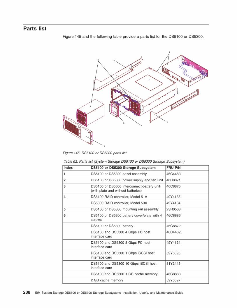
Parts listFigure 145 and the following table provide a parts list for the DS5100 or DS5300.
Table 62. Parts list (System Storage DS5100 or DS5300 Storage Subsystem)
Index DS5100 or DS5300 Storage Subsystem FRU P/N
1 DS5100 or DS5300 bezel assembly 46C4483
2 DS5100 or DS5300 power supply and fan unit 46C8871
3 DS5100 or DS5300 interconnect-battery unit(with plate and without batteries)
46C8875
4 DS5100 RAID controller, Model 51A 49Y4133
DS5300 RAID controller, Model 53A 49Y4134
5 DS5100 or DS5300 mounting rail assembly 23R0538
6 DS5100 or DS5300 battery cover/plate with 4screws
46C8886
DS5100 or DS5300 battery 46C8872
DS5100 and DS5300 4 Gbps FC hostinterface card
46C4482
DS5100 and DS5300 8 Gbps FC hostinterface card
49Y4124
DS5100 and DS5300 1 Gbps iSCSI hostinterface card
59Y5095
DS5100 and DS5300 10 Gbps iSCSI hostinterface card
81Y2445
DS5100 and DS5300 1 GB cache memory 46C8888
2 GB cache memory 59Y5097
1
2
3
5ds50006
5
4
6
Figure 145. DS5100 or DS5300 parts list
238 IBM System Storage DS5100 or DS5300 Storage Subsystem: Installation, User’s, and Maintenance Guide

Table 62. Parts list (System Storage DS5100 or DS5300 Storage Subsystem) (continued)
Index DS5100 or DS5300 Storage Subsystem FRU P/N
4 GB cache memory 59Y5098
DS5100 and DS5300 4 GB flash memory 46C8890
8 GB flash memory 59Y5099
LC wrap plug assembly 39M5914
LC-SC fibre channel cable adapter 23R0539
Power cord, 2.8–meter (9–ft.) 39M5247
Power cord, line jumper, high voltage 39M5377
4 Gbps SFP module 22R6443
8 Gbps SFP module 49Y4123
10 Gbps SFP+ module 81Y2493
Cable, 1–meter fiber-optic 39M5699
Cable, 5–meter fiber-optic 39M5700
Cable, 10–meter OM3 fiber-optic 45W2222
Cable, 25–meter fiber-optic 39M5701
1 Gbps iSCSI host interface card port coverplate with opening
59Y5432
10 Gbps iSCSI host interface card port coverplate with opening
94Y8404
FC host interface card port cover plate withopening
49Y4158
Blank host interface card port cover plate 69Y2769
Seven-segment display sequence codes and their causesIf an error occurs during the controller or ESM boot process and the NeedsAttention LED is on, the numeric display shows diagnostic information as asequence of 2-digit diagnostic code. The following figure shows the seven-segmentalphanumeric characters.
Chapter 6. Hardware maintenance 239
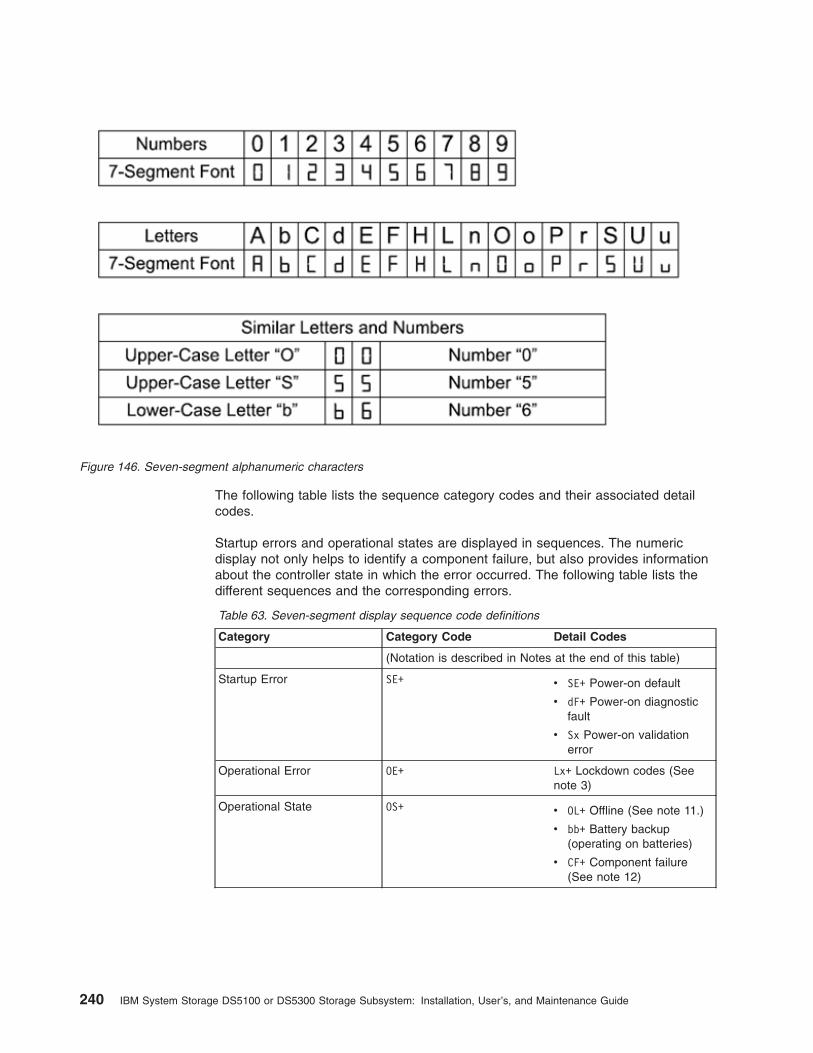
The following table lists the sequence category codes and their associated detailcodes.
Startup errors and operational states are displayed in sequences. The numericdisplay not only helps to identify a component failure, but also provides informationabout the controller state in which the error occurred. The following table lists thedifferent sequences and the corresponding errors.
Table 63. Seven-segment display sequence code definitions
Category Category Code Detail Codes
(Notation is described in Notes at the end of this table)
Startup Error SE+ v SE+ Power-on default
v dF+ Power-on diagnosticfault
v Sx Power-on validationerror
Operational Error OE+ Lx+ Lockdown codes (Seenote 3)
Operational State OS+ v OL+ Offline (See note 11.)
v bb+ Battery backup(operating on batteries)
v CF+ Component failure(See note 12)
Figure 146. Seven-segment alphanumeric characters
240 IBM System Storage DS5100 or DS5300 Storage Subsystem: Installation, User’s, and Maintenance Guide

Table 63. Seven-segment display sequence code definitions (continued)
Category Category Code Detail Codes
Component Failure CF+ v dx+ Processor/CacheDIMM (x = location. Seenote 6.)
v Cx+ Cache DIMM (x =location. See note 7.)
v Px+ Processor DIMM (x =location. See note 8.)
v Hx+ Host card (x =location)
v Fx+ Flash drive (x =location)
v b1+ Base controller card
Diagnostic Failure dE+ Lx+ Lockdown code (Seenote 3)
Category Delimiter dash+ Separator betweencategory-detail code pairs(See notes 4 and 9)
End-Of-Sequence Delimiter blank- End-of-sequence indicator(See notes 5 and 10)
Notes:
1. xy+ Indicates that the diagnostic LED is lit.
2. xy- Indicates that the diagnostic LED is turned off.
3. Lx+ Lockdown codes (See Table 65 on page 243)
4. dash+ All segments are off except the middle segments and the diagnostic light is on.
5. blank- All segments are off and the diagnostic light is off.
6. dx+ Used when there is a single memory system for processor and data cache.
7. Cx+ Used when there are separate processor and data cache memory systems.
8. Px+ Used when there are separate processor and data cache memory systems.
9. Category-Detail separator is used when there is more than one category-detail pair inthe sequence. For examples, see Table 64
10. End-of-sequence indicator is automatically inserted by hardware at the end of thesequence. Example: SE+ 88+ blank- (repeat)
11. If an enclosure ID is being displayed, this sequence is programmed to display. Thecontroller is then held in reset.
12. The enclosure ID is nominally displayed during normal operation. This operational stateis displayed if an internal controller component failure occurs while the controller isonline. An additional detail code identifies the failed component as defined for theComponent Failure category. This sequence will continue to display even if thecontroller is later placed offline (held in reset) to service the failed component.
Table 64. Repeating sequences on the seven-segment display and corresponding errors
Repeating Sequence Startup and Operational Error
Controller power-on failure:
SE+ 88+ blank- v Initial phase of normal power-on controllerinsertion
v Insertion of a controller while held in reset
Operational failure:
Chapter 6. Hardware maintenance 241
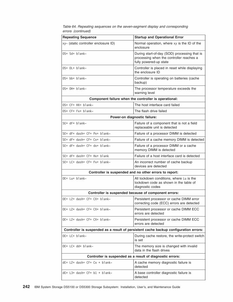
Table 64. Repeating sequences on the seven-segment display and correspondingerrors (continued)
Repeating Sequence Startup and Operational Error
xy- (static controller enclosure ID) Normal operation, where xy is the ID of theenclosure
OS+ Sd+ blank- During start-of-day (SOD) processing that isprocessing when the controller reaches afully powered-up state
OS+ OL+ blank- Controller is placed in reset while displayingthe enclosure ID
OS+ bb+ blank- Controller is operating on batteries (cachebackup)
OS+ OH+ blank- The processor temperature exceeds thewarning level
Component failure when the controller is operational:
OS+ CF+ HX+ blank- The host interface card failed
OS+ CF+ Fx+ blank- The flash drive failed
Power-on diagnostic failure:
SE+ dF+ blank- Failure of a component that is not a fieldreplaceable unit is detected
SE+ dF+ dash+ CF+ Px+ blank- Failure of a processor DIMM is detected
SE+ dF+ dash+ CF+ Cx+ blank- Failure of a cache memory DIMM is detected
SE+ dF+ dash+ CF+ dx+ blank- Failure of a processor DIMM or a cachememory DIMM is detected
SE+ dF+ dash+ CF+ Hx+ blank Failure of a host interface card is detected
SE+ LC+ dash+ CF+ Fx+ blank- An incorrect number of cache backupdevices are detected
Controller is suspended and no other errors to report:
OE+ Lu+ blank- All lockdown conditions, where Lu is thelockdown code as shown in the table ofdiagnostic codes
Controller is suspended because of component errors:
OE+ L2+ dash+ CF+ CX+ blank- Persistent processor or cache DIMM errorcorrecting code (ECC) errors are detected
OE+ L2+ dash+ CF+ CX+ blank- Persistent processor or cache DIMM ECCerrors are detected
OE+ L2+ dash+ CF+ CX+ blank- Persistent processor or cache DIMM ECCerrors are detected
Controller is suspended as a result of persistent cache backup configuration errors:
OE+ LC+ blank- During cache restore, the write-protect switchis set
OE+ LC+ dd+ blank- The memory size is changed with invaliddata in the flash drives
Controller is suspended as a result of diagnostic errors:
dE+ L2+ dash+ CF+ Cx + blank- A cache memory diagnostic failure isdetected
dE+ L3+ dash+ CF+ b1 + blank- A base controller diagnostic failure isdetected
242 IBM System Storage DS5100 or DS5300 Storage Subsystem: Installation, User’s, and Maintenance Guide
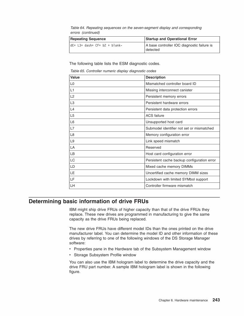
Table 64. Repeating sequences on the seven-segment display and correspondingerrors (continued)
Repeating Sequence Startup and Operational Error
dE+ L3+ dash+ CF+ b2 + blank- A base controller IOC diagnostic failure isdetected
The following table lists the ESM diagnostic codes.
Table 65. Controller numeric display diagnostic codes
Value Description
L0 Mismatched controller board ID
L1 Missing interconnect canister
L2 Persistent memory errors
L3 Persistent hardware errors
L4 Persistent data protection errors
L5 ACS failure
L6 Unsupported host card
L7 Submodel identifier not set or mismatched
L8 Memory configuration error
L9 Link speed mismatch
LA Reserved
LB Host card configuration error
LC Persistent cache backup configuration error
LD Mixed cache memory DIMMs
LE Uncertified cache memory DIMM sizes
LF Lockdown with limited SYMbol support
LH Controller firmware mismatch
Determining basic information of drive FRUsIBM might ship drive FRUs of higher capacity than that of the drive FRUs theyreplace. These new drives are programmed in manufacturing to give the samecapacity as the drive FRUs being replaced.
The new drive FRUs have different model IDs than the ones printed on the drivemanufacturer label. You can determine the model ID and other information of thesedrives by referring to one of the following windows of the DS Storage Managersoftware:
v Properties pane in the Hardware tab of the Subsystem Management window
v Storage Subsystem Profile window
You can also use the IBM hologram label to determine the drive capacity and thedrive FRU part number. A sample IBM hologram label is shown in the followingfigure.
Chapter 6. Hardware maintenance 243
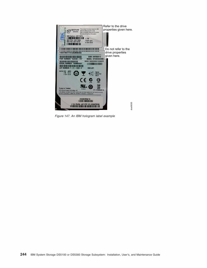
Do not refer to thedrive propertiesgiven here.
Refer to the driveproperties given here.
dcsi0
035
Figure 147. An IBM hologram label example
244 IBM System Storage DS5100 or DS5300 Storage Subsystem: Installation, User’s, and Maintenance Guide
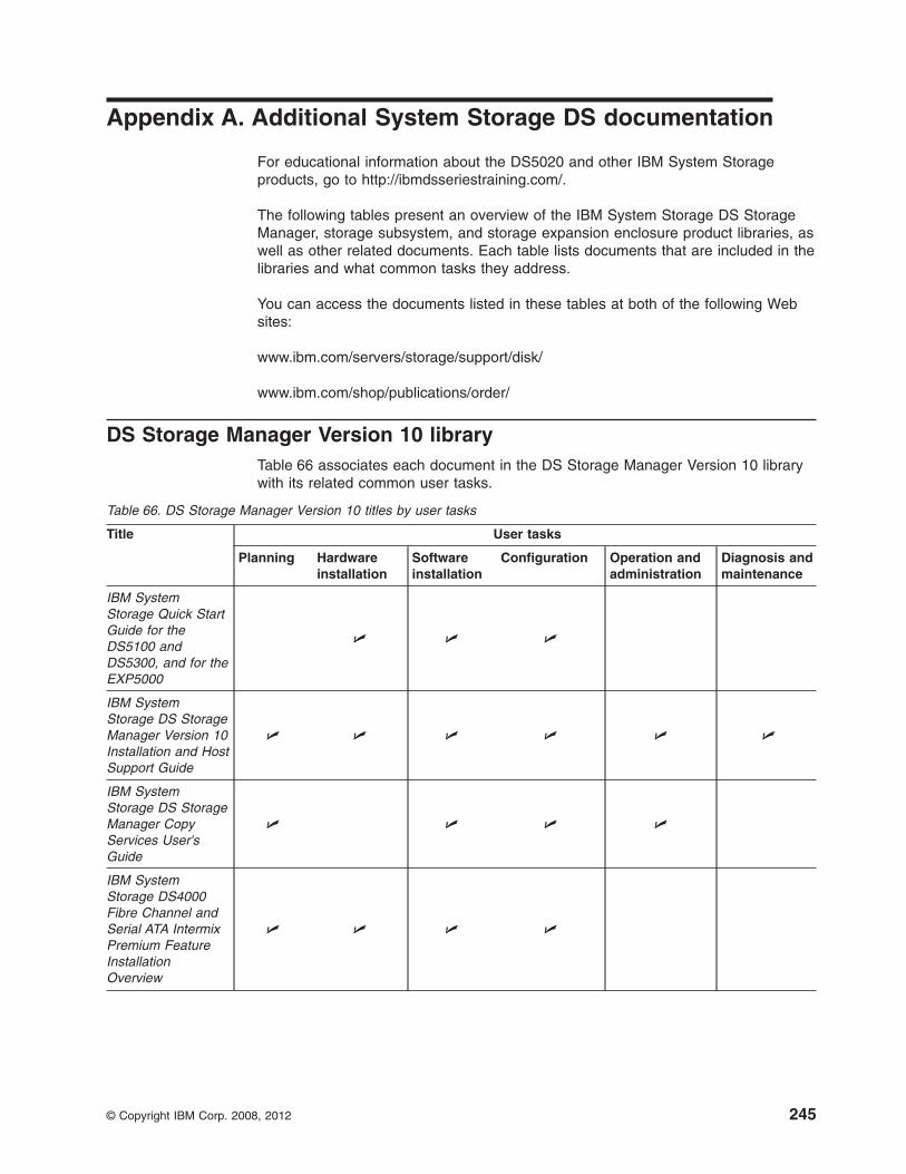
Appendix A. Additional System Storage DS documentation
For educational information about the DS5020 and other IBM System Storageproducts, go to http://ibmdsseriestraining.com/.
The following tables present an overview of the IBM System Storage DS StorageManager, storage subsystem, and storage expansion enclosure product libraries, aswell as other related documents. Each table lists documents that are included in thelibraries and what common tasks they address.
You can access the documents listed in these tables at both of the following Websites:
www.ibm.com/servers/storage/support/disk/
www.ibm.com/shop/publications/order/
DS Storage Manager Version 10 libraryTable 66 associates each document in the DS Storage Manager Version 10 librarywith its related common user tasks.
Table 66. DS Storage Manager Version 10 titles by user tasks
Title User tasks
Planning Hardwareinstallation
Softwareinstallation
Configuration Operation andadministration
Diagnosis andmaintenance
IBM SystemStorage Quick StartGuide for theDS5100 andDS5300, and for theEXP5000
U U U
IBM SystemStorage DS StorageManager Version 10Installation and HostSupport Guide
U U U U U U
IBM SystemStorage DS StorageManager CopyServices User'sGuide
U U U U
IBM SystemStorage DS4000Fibre Channel andSerial ATA IntermixPremium FeatureInstallationOverview
U U U U
© Copyright IBM Corp. 2008, 2012 245
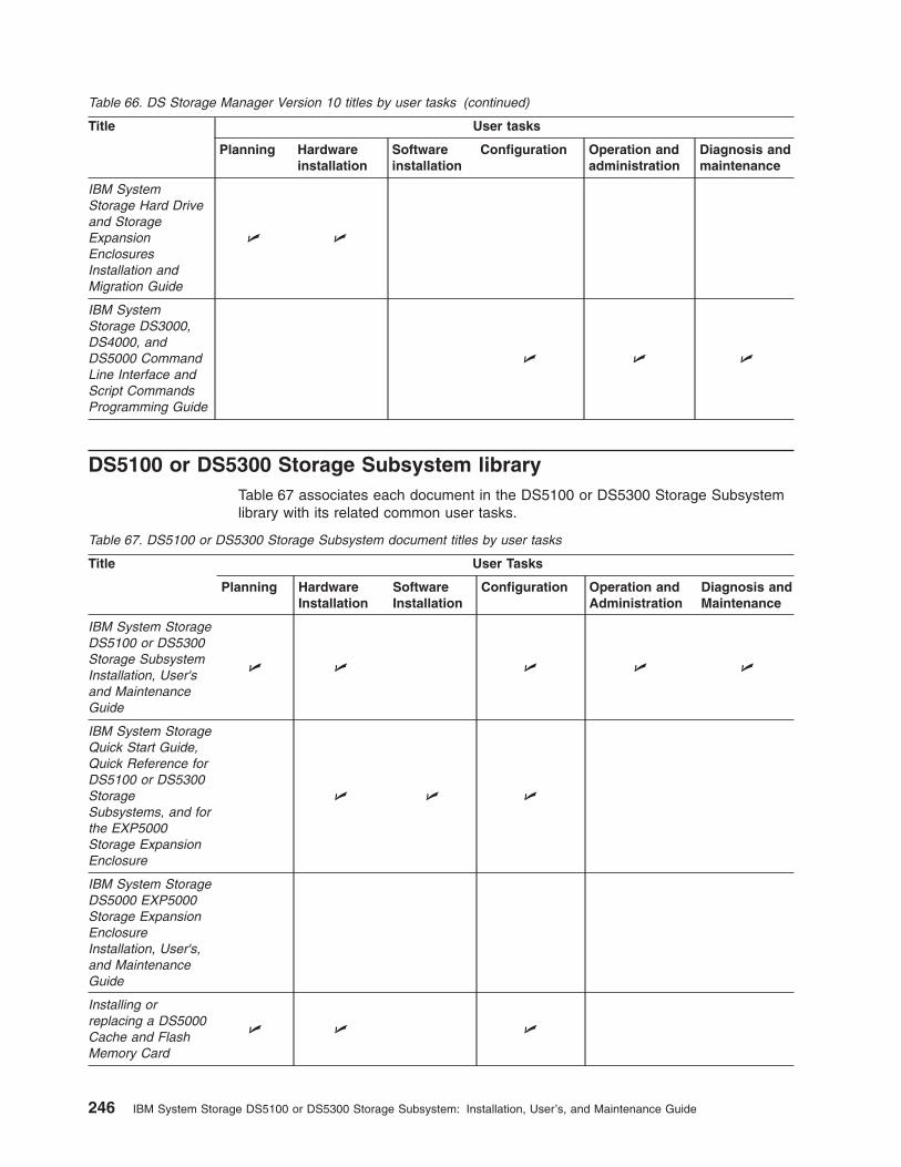
Table 66. DS Storage Manager Version 10 titles by user tasks (continued)
Title User tasks
Planning Hardwareinstallation
Softwareinstallation
Configuration Operation andadministration
Diagnosis andmaintenance
IBM SystemStorage Hard Driveand StorageExpansionEnclosuresInstallation andMigration Guide
U U
IBM SystemStorage DS3000,DS4000, andDS5000 CommandLine Interface andScript CommandsProgramming Guide
U U U
DS5100 or DS5300 Storage Subsystem libraryTable 67 associates each document in the DS5100 or DS5300 Storage Subsystemlibrary with its related common user tasks.
Table 67. DS5100 or DS5300 Storage Subsystem document titles by user tasks
Title User Tasks
Planning HardwareInstallation
SoftwareInstallation
Configuration Operation andAdministration
Diagnosis andMaintenance
IBM System StorageDS5100 or DS5300Storage SubsystemInstallation, User'sand MaintenanceGuide
U U U U U
IBM System StorageQuick Start Guide,Quick Reference forDS5100 or DS5300StorageSubsystems, and forthe EXP5000Storage ExpansionEnclosure
U U U
IBM System StorageDS5000 EXP5000Storage ExpansionEnclosureInstallation, User's,and MaintenanceGuide
Installing orreplacing a DS5000Cache and FlashMemory Card
U U U
246 IBM System Storage DS5100 or DS5300 Storage Subsystem: Installation, User’s, and Maintenance Guide

Table 67. DS5100 or DS5300 Storage Subsystem document titles by user tasks (continued)
Title User Tasks
Planning HardwareInstallation
SoftwareInstallation
Configuration Operation andAdministration
Diagnosis andMaintenance
Installing orreplacing a DS5000Host Interface Card
U U U
DS5020 Storage subsystem libraryTable 68 associates each document in the DS5020 Storage subsystem library withits related common user tasks.
Table 68. DS5020 Storage subsystem document titles by user tasks
Title User Tasks
Planning HardwareInstallation
SoftwareInstallation
Configuration Operation andAdministration
Diagnosis andMaintenance
IBM System StorageDS5020 StorageSubsystemInstallation, User'sand MaintenanceGuide
U U U U U
IBM System StorageQuick start guide,Quick reference forthe DS5020 andDS4200, Sections 2,3, and 4 also forinstalling theEXP810 andEXP420
U U U
IBM System StorageDS5020 Quick StartGuide
U U U
IBM System StorageDS5020 Installation,User's, andMaintenance Guide
U U U U U U
Appendix A. Additional System Storage DS documentation 247
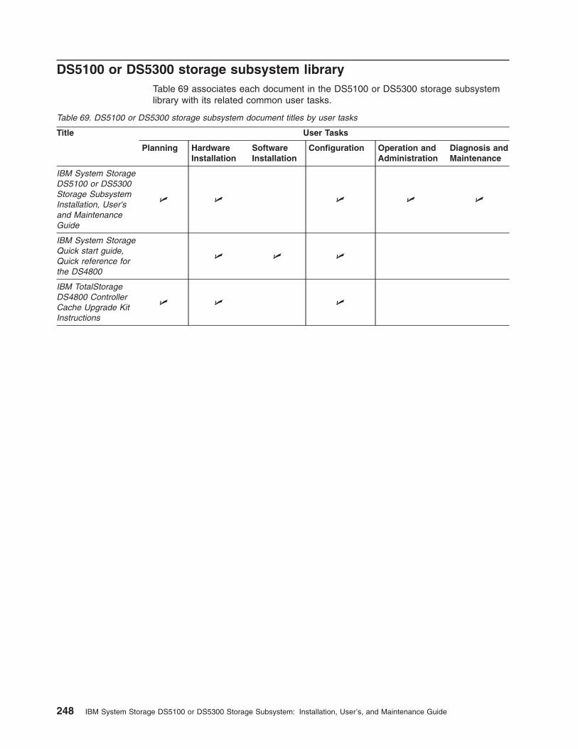
DS5100 or DS5300 storage subsystem libraryTable 69 associates each document in the DS5100 or DS5300 storage subsystemlibrary with its related common user tasks.
Table 69. DS5100 or DS5300 storage subsystem document titles by user tasks
Title User Tasks
Planning HardwareInstallation
SoftwareInstallation
Configuration Operation andAdministration
Diagnosis andMaintenance
IBM System StorageDS5100 or DS5300Storage SubsystemInstallation, User'sand MaintenanceGuide
U U U U U
IBM System StorageQuick start guide,Quick reference forthe DS4800
U U U
IBM TotalStorageDS4800 ControllerCache Upgrade KitInstructions
U U U
248 IBM System Storage DS5100 or DS5300 Storage Subsystem: Installation, User’s, and Maintenance Guide

DS4700 storage subsystem libraryTable 70 associates each document in the DS4700 storage subsystem library withits related common user tasks.
Table 70. DS4700 storage subsystem document titles by user tasks
Title User Tasks
Planning HardwareInstallation
SoftwareInstallation
Configuration Operation andAdministration
Diagnosis andMaintenance
IBM System StorageDS4700 StorageSubsystemInstallation, User'sand MaintenanceGuide
U U U U U
IBM System StorageQuick start guide,Quick reference forthe DS4700 andDS4200, Sections 2,3, and 4 also forinstalling theEXP810 andEXP420
U U U
IBM TotalStorageDS4500 StorageSubsystemInstallation, User's,and MaintenanceGuide
U U U
IBM TotalStorageDS4500 StorageSubsystem CablingInstructions
U U
IBM TotalStorageDS4500 RackMountingInstructions
U U
Appendix A. Additional System Storage DS documentation 249

DS4500 storage subsystem libraryTable 71 associates each document in the DS4500 storage subsystem library withits related common user tasks.
Table 71. DS4500 storage subsystem document titles by user tasks
Title User Tasks
Planning HardwareInstallation
SoftwareInstallation
Configuration Operation andAdministration
Diagnosis andMaintenance
IBM TotalStorageDS4500 StorageSubsystemInstallation, User's,and MaintenanceGuide
U U U U U
IBM TotalStorageDS4500 StorageSubsystem CablingInstructions
U U
IBM TotalStorageDS4500 RackMountingInstructions
U U
250 IBM System Storage DS5100 or DS5300 Storage Subsystem: Installation, User’s, and Maintenance Guide
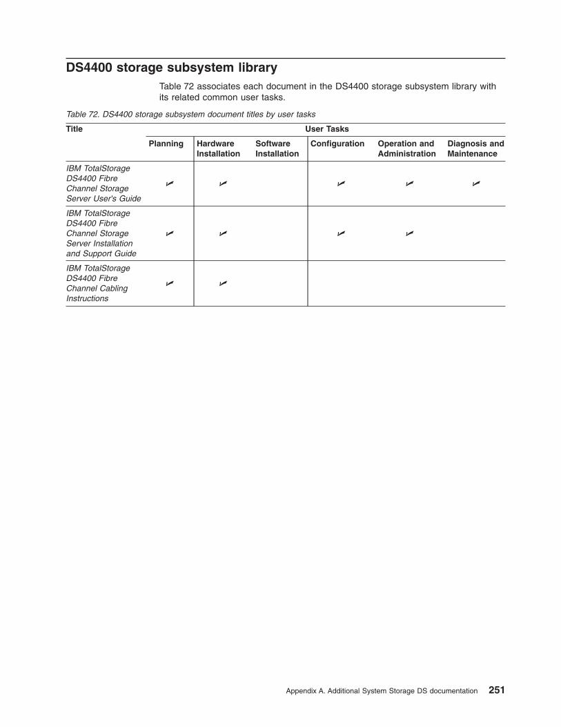
DS4400 storage subsystem libraryTable 72 associates each document in the DS4400 storage subsystem library withits related common user tasks.
Table 72. DS4400 storage subsystem document titles by user tasks
Title User Tasks
Planning HardwareInstallation
SoftwareInstallation
Configuration Operation andAdministration
Diagnosis andMaintenance
IBM TotalStorageDS4400 FibreChannel StorageServer User's Guide
U U U U U
IBM TotalStorageDS4400 FibreChannel StorageServer Installationand Support Guide
U U U U
IBM TotalStorageDS4400 FibreChannel CablingInstructions
U U
Appendix A. Additional System Storage DS documentation 251
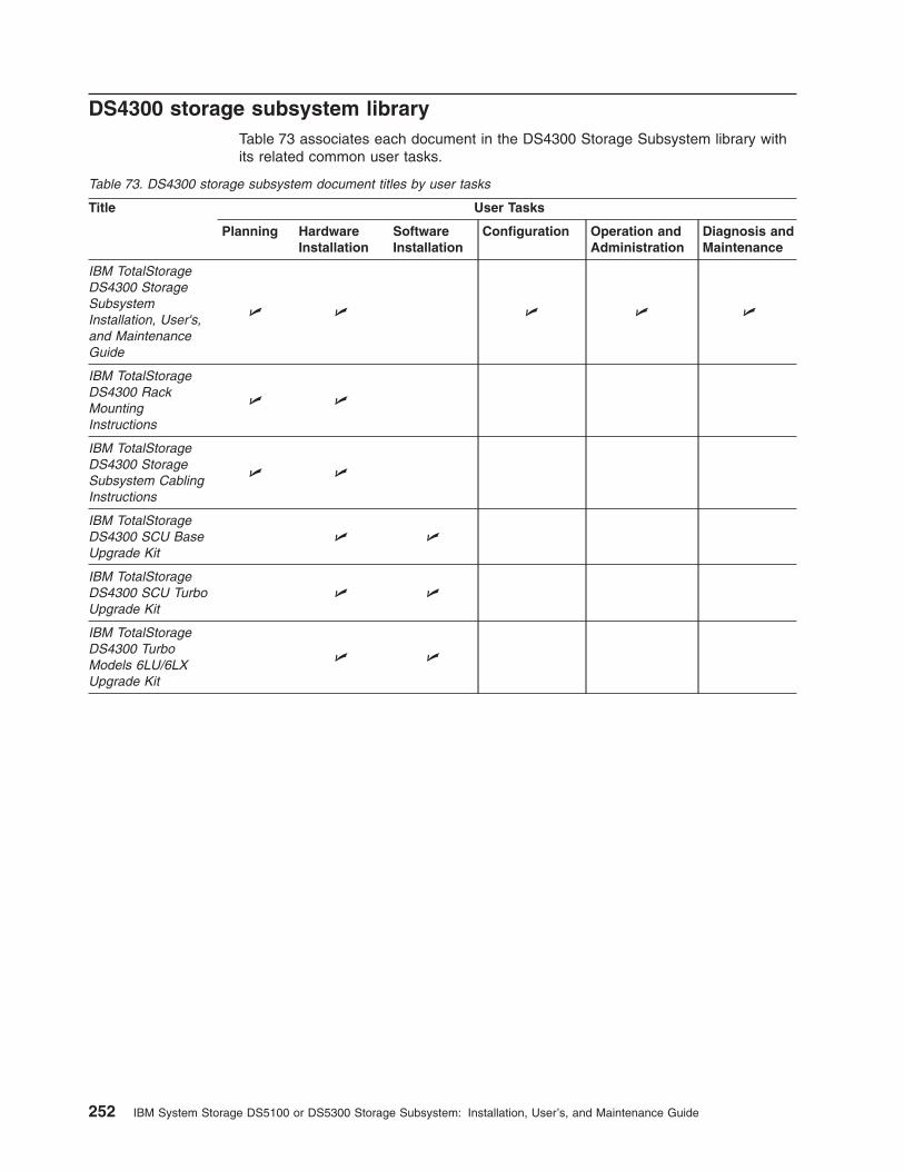
DS4300 storage subsystem libraryTable 73 associates each document in the DS4300 Storage Subsystem library withits related common user tasks.
Table 73. DS4300 storage subsystem document titles by user tasks
Title User Tasks
Planning HardwareInstallation
SoftwareInstallation
Configuration Operation andAdministration
Diagnosis andMaintenance
IBM TotalStorageDS4300 StorageSubsystemInstallation, User's,and MaintenanceGuide
U U U U U
IBM TotalStorageDS4300 RackMountingInstructions
U U
IBM TotalStorageDS4300 StorageSubsystem CablingInstructions
U U
IBM TotalStorageDS4300 SCU BaseUpgrade Kit
U U
IBM TotalStorageDS4300 SCU TurboUpgrade Kit
U U
IBM TotalStorageDS4300 TurboModels 6LU/6LXUpgrade Kit
U U
252 IBM System Storage DS5100 or DS5300 Storage Subsystem: Installation, User’s, and Maintenance Guide

DS4200 Express storage subsystem libraryTable 74 associates each document in the DS4200 Express storage subsystemlibrary with its related common user tasks.
Table 74. DS4200 Express storage subsystem document titles by user tasks
Title User Tasks
Planning HardwareInstallation
SoftwareInstallation
Configuration Operation andAdministration
Diagnosis andMaintenance
IBM System StorageDS4200 ExpressStorage SubsystemInstallation, User'sand MaintenanceGuide
U U U U U
IBM System StorageQuick start guide,Quick reference forthe DS4700 andDS4200, Sections 2,3, and 4 also forinstalling theEXP810 andEXP420
U U U
Appendix A. Additional System Storage DS documentation 253
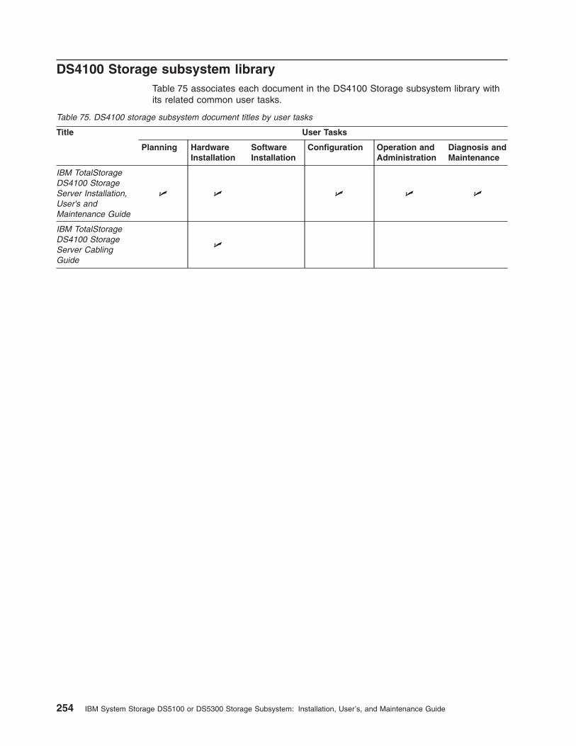
DS4100 Storage subsystem libraryTable 75 associates each document in the DS4100 Storage subsystem library withits related common user tasks.
Table 75. DS4100 storage subsystem document titles by user tasks
Title User Tasks
Planning HardwareInstallation
SoftwareInstallation
Configuration Operation andAdministration
Diagnosis andMaintenance
IBM TotalStorageDS4100 StorageServer Installation,User's andMaintenance Guide
U U U U U
IBM TotalStorageDS4100 StorageServer CablingGuide
U
254 IBM System Storage DS5100 or DS5300 Storage Subsystem: Installation, User’s, and Maintenance Guide

DS4000 and DS4000 storage expansion enclosure documentsTable 76 associates each of the following documents with its related common usertasks.
Table 76. DS4000 and DS4000 storage expansion enclosure document titles by user tasks
Title User Tasks
Planning HardwareInstallation
SoftwareInstallation
Configuration Operation andAdministration
Diagnosis andMaintenance
IBM System StorageEXP520 ExpansionEnclosureInstallation, User's,and MaintenanceGuide
U U U U U U
IBM System StorageDS4000 EXP810Storage ExpansionEnclosureInstallation, User's,and MaintenanceGuide
U U U U U
IBM System StorageQuick start guide,Quick reference forthe DS5020 andDS4200, Sections 2,3, and 4 also forinstalling theEXP810 andEXP420
U U U
IBM TotalStorageDS4000 EXP700and EXP710Storage ExpansionEnclosuresInstallation, User's,and MaintenanceGuide
U U U U U
IBM EXP500Installation andUser's Guide
U U U U U
IBM System StorageDS4000 EXP420Storage ExpansionEnclosureInstallation, User's,and MaintenanceGuide
U U U U U
IBM System StorageDS4000 Hard Driveand StorageExpansionEnclosuresInstallation andMigration Guide
U U
Appendix A. Additional System Storage DS documentation 255

Other DS4000 and DS4000-related documentsTable 77 associates each of the following documents with its related common usertasks.
Table 77. DS4000 and DS4000-related document titles by user tasks
Title User Tasks
Planning HardwareInstallation
SoftwareInstallation
Configuration Operation andAdministration
Diagnosis andMaintenance
IBM SafetyInformation
U
IBM TotalStorageDS4000 HardwareMaintenance Manual¹
U
IBM System StorageDS4000 ProblemDetermination Guide
U
IBM Fibre ChannelPlanning andIntegration: User'sGuide and ServiceInformation
U U U U
IBM TotalStorageDS4000 FC2-133Host Bus AdapterInstallation andUser's Guide
U U
IBM TotalStorageDS4000 FC2-133Dual Port Host BusAdapter Installationand User's Guide
U U
IBM Netfinity® FibreChannel CablingInstructions
U
IBM Fibre ChannelSAN ConfigurationSetup Guide
U U U U
Notes:
1. The IBM TotalStorage DS4000 Hardware Maintenance Manual does not contain maintenance information for theIBM System Storage DS4100, DS4200, DS4300, DS4500, DS4700, or DS4800 Storage subsystems. You can findmaintenance information for these products in the IBM System Storage DSx000 Storage Subsystem Installation,User's, and Maintenance Guide for the particular subsystem.
256 IBM System Storage DS5100 or DS5300 Storage Subsystem: Installation, User’s, and Maintenance Guide

Appendix B. Records
Whenever you add options to your DS5100 or DS5300, be sure to update theinformation in this appendix. Accurate, up-to-date records make it easier to addother options and provide needed data whenever you contact your IBM technicalsupport representative.
Identification numbersRecord and retain the following information. The machine type, model number, andserial number are located on top of each RAID controller unit. The RAID controllerMAC addresses are located near the Ethernet ports on each RAID controller, theiSCSI port MAC addresses are near the iSCSI ports, as shown in Figure 148 onpage 258.
Product name: IBM System Storage DS5100 or DS5300 StorageSubsystem
Machine type: 1818Model number:Serial number:RAID controller MAC addresses:Controller firmware version:
Port name MAC address IP address Subnet mask
Controller Amanagement port 1
Controller Amanagement port 2
Controller Bmanagement port 1
Controller Bmanagement port 2
Controller A iSCSIport 1
Controller A iSCSIport 2
Controller A iSCSIport 3
Controller A iSCSIport 4
Controller B iSCSIport 1
Controller B iSCSIport 2
Controller B iSCSIport 3
Controller B iSCSIport 4
© Copyright IBM Corp. 2008, 2012 257

MAC address label (Controller A)
MAC address label (Controller B)
iSCSI portMAC address label
Figure 148. Location of MAC address labels
258 IBM System Storage DS5100 or DS5300 Storage Subsystem: Installation, User’s, and Maintenance Guide

Appendix C. Rack mounting templates
This appendix provides duplicate copies of the rack mounting templates. If you wantto tear out the templates from this document for easier use, use these copies ratherthan those provided in “Installing the support rails” on page 40.
Use the following templates (Figure 149 on page 260 and Figure 150 on page 261)to identify the proper locations for inserting M5 screws when mounting the supportrails and DS5100 or DS5300 in a rack cabinet. The locations for the M5 screws arehighlighted in the templates.
The DS5100 or DS5300 is 4 U high. Align the template with the rack at a Uboundary. U boundaries are shown as horizontal dashed lines in the rack mountingtemplates.
Note: The mounting holes that are shown in the following templates are square.The holes in your rack cabinet might be round or square.
© Copyright IBM Corp. 2008, 2012 259

FRONTRack Mounting
Template
0 U
2 U
3 U
1 U
4 U
Rail assembly(Front left)
Rail assembly(Front right)
Rail assembly(Front left)
Rail assembly(Front right)
4 U
3 U
2 U
1 U
0 UFront
Figure 149. DS5100 or DS5300 front rack mounting template
260 IBM System Storage DS5100 or DS5300 Storage Subsystem: Installation, User’s, and Maintenance Guide

REARRack Mounting
Template
Rail assembly(Rear left)
Rail assembly(Rear right)
4 U
3 U
2 U
1 U
0 U0 U
2 U
3 U
1 U
4 U
Printed in the U.S.A
Figure 150. DS5100 or DS5300 rear rack mounting template
Appendix C. Rack mounting templates 261

262 IBM System Storage DS5100 or DS5300 Storage Subsystem: Installation, User’s, and Maintenance Guide
Appendix D. Specifications for non-IBM rack installation
The following instructions provide safety requirements and rack specifications forinstalling the DS5100 or DS5300 storage subsystem and DS5100 or DS5300storage expansion enclosure into an non-IBM rack.
Note: The information in this section applies to 19–inch racks. It is yourresponsibility, working with your rack manufacturer, to ensure that thenon-IBM rack chosen meets the safety requirements and specifications listedin this section.
General safety requirements for IBM products installed in a non-IBMrack or cabinet
The general safety requirements for IBM products installed in non-IBM racks are:
1. Any product or component that plugs into either an IBM power distribution unitor mains power (via a power cord), or uses any voltage over 42 V ac or 60 Vdc (considered to be hazardous voltage) must be Safety Certified by aNationally Recognized Test Laboratory (NRTL) for the country in which it willbe installed.
Some of the items that require safety certification may include: the rack orcabinet (if it contains electrical components integral to the rack or cabinet), fantrays, power distribution unit, uninterruptible power supplies, multi-outlet strips,or any other products installed in the rack or cabinet that connect to hazardousvoltage.
Examples of OSHA-approved NRTLs for the U.S.:
v UL
v ETL
v CSA (with CSA NRTL or CSA US mark)
Examples of approved NRTLs for Canada:
a. UL (Ulc mark)
b. ETL (ETLc mark)
c. CSA
The European Union requires a CE mark and a Manufacturer's Declaration ofConformity (DOC).
Certified products should have the NRTL logos or marks somewhere on theproduct or product label. However, proof of certification must be madeavailable to IBM upon request. Proof consists of such items as copies of theNRTL license or certificate, a CB Certificate, a Letter of Authorization to applythe NRTL mark, the first few pages of the NRTL certification report, Listing inan NRTL publication, or a copy of the UL Yellow Card. Proof should containthe manufacturer's name, product type and model, standard to which it wascertified, the NRTL name or logo, the NRTL file number or license number, anda list of any Conditions of Acceptance or Deviations. A Manufacturer'sDeclaration is not proof of certification by an NRTL.
2. The rack or cabinet must meet all electrical and mechanical safety legalrequirements for the country in which it is installed.
The rack or cabinet must be free of exposed hazards (such as voltages over60 V dc or 42 V ac, energy over 240 VA, sharp edges, mechanical pinchpoints, or hot surfaces).
© Copyright IBM Corp. 2008, 2012 263
3. There must be an accessible and unambiguous disconnect device for eachproduct in the rack, including any power distribution unit.
A disconnect device may consist of either the plug on the power cord (if thepower cord is no longer than 1.8 m (6 ft.)), the appliance inlet receptacle (if thepower cord is of a detachable type), or a power on/off switch, or anEmergency Power Off switch on the rack, provided all power is removed fromthe rack or product by the disconnect device.
If the rack/or cabinet has electrical components (such as fan trays or lights),the rack must have an accessible and unambiguous disconnect device.
4. The rack or cabinet, power distribution unit and multi-outlet strips, and productsinstalled in the rack or cabinet must all be properly grounded to the customerfacility ground.
There must be no more than 0.1 Ohms between the ground pin of the powerdistribution unit or rack plug and any touchable metal or conductive surface onthe rack and on the products installed in the rack. Grounding method mustcomply with applicable country's electric code (such as NEC or CEC). Groundcontinuity can be verified by your IBM service personnel, after the installationis completed, and should be verified prior to the first service activity.
5. The voltage rating of the power distribution unit and multi-outlet strips must becompatible with the products plugged into them.
The power distribution unit or multi-outlet strips current and power ratings arerated at 80 percent of the building supply circuit (as required by the NationalElectrical Code and the Canadian Electrical Code). The total load connected tothe power distribution unit must be less than the rating of the power distributionunit. For example, a power distribution unit with a 30 A connection will be ratedfor a total load of 24 A (30 A x 80 percent). Therefore, the sum of allequipment connected to the power distribution unit in this example must belower than the 24 A rating.
If an uninterruptible power supply is installed, it must meet all the aboveelectrical safety requirements as described for a power distribution unit(including certification by an NRTL).
6. The rack or cabinet, power distribution unit, uninterruptible power supply,multi-outlet strips and all products in the rack or cabinet must be installedaccording to the manufacturer's instructions, and in accordance with allnational, state or province, and local codes and laws.
The rack or cabinet, power distribution unit, uninterruptible power supply,multi-outlet strips and all products in the rack or cabinet must be used asintended by the manufacturer (per manufacturer's product documentation andmarketing literature).
7. All documentation for use and installation of the rack or cabinet, powerdistribution unit, uninterruptible power supply, and all products in the rack orcabinet, including safety information, must be available on-site.
8. If there is more than one source of power in the rack cabinet, there must beclearly visible safety labels for "Multiple Power Source" (in the languagesrequired for the country in which the product is installed).
9. If the rack or cabinet or any products installed in the cabinet had safety orweight labels applied by the manufacturer, they must be intact and translatedinto the languages required for the country in which the product is installed.
10. The rack or cabinet configuration must comply with all IBM requirements for"safe to service" (contact your IBM Installation Planning Representative forassistance in determining if the environment is safe).
264 IBM System Storage DS5100 or DS5300 Storage Subsystem: Installation, User’s, and Maintenance Guide
There must be no unique maintenance procedures or tools required forservice.
11. Elevated service installations, where the product(s) to be serviced are installedbetween 1.5 m and 3.7 m (5 ft. and 12 ft.) above the floor, require theavailability of an OSHA- and CSA-approved nonconductive step ladder. If aladder is required for service, the customer must supply the OSHA- and CSA-approved nonconductive step ladder (unless other arrangements have beenmade with the local IBM Service Branch Office). Products installed over 2.9 m(9 ft.) above the floor requires a Special Bid to be completed before they canbe serviced by IBM service personnel.
For products not intended for rack-mounting to be serviced by IBM, theproducts and parts that will be replaced as part of that service must not weighover 11.4 kg (25 lb). (Contact your Installation Planning Representative if indoubt).
12. There must not be any special education or training required for safe servicingof any of the product(s) installed in the racks. (Contact your InstallationPlanning Representative if in doubt).
Rack specificationsWhen installing a DS5100 or DS5300 storage subsystem or DS5100 or DS5300storage expansion enclosure into a non-IBM rack, follow the specifications below.
1. The rack or cabinet must meet the EIA Standard EIA-310-D for 19-inch rackspublished August 24, 1992. The EIA-310-D standard specifies internaldimensions, for example, the width of the rack opening (width of the chassis),the width of the module mounting flanges, the mounting hole spacing, and thedepth of the mounting flanges. The EIA-310-D standard does not control theoverall external width of the rack. There are no restrictions on the location ofside walls and corner posts relative to the internal mounting space.
The front rack opening must be 451 mm wide + 0.75 mm (17.75 in. + 0.03 in.),and the rail-mounting holes must be 465 mm + 0.8 mm (18.3 in. + 0.03 in.)apart on center (horizontal width between vertical columns of holes on the twofront-mounting flanges and on the two rear-mounting flanges).
Appendix D. Specifications for non-IBM rack installation 265

Top view of non-IBM rack specifications dimensions
The vertical distance between mounting holes must consist of sets of threeholes spaced (from bottom to top) 15.9 mm (0.625 in.), 15.9 mm (0.625 in.), and12.67 mm (0.5 in.) on center (making each three hole set of vertical holespacing 44.45 mm (1.75 in.) apart on center). The front and rear mountingflanges in the rack or cabinet must be 719 mm (28.3 in.) apart and the internalwidth bounded by the mounting flanges at least 494 mm (19.45 in.), for the IBMStorage System or eServer™ rails to fit in your rack or cabinet (see Figure 151).
nonibm_topview
Back, No Door
571 mm (22.50 in.)
Drawer RailMounting Flanges 494 mm (19.45 in.)
Front, No Door
451 mm (17.46 in.)
494 mm (19.45 in.)
203 mm (8.0 in.)
719 mm (28.31 in.)
51 mm (2.01 in)
Figure 151. Top View of non-IBM Rack Specifications Dimensions
266 IBM System Storage DS5100 or DS5300 Storage Subsystem: Installation, User’s, and Maintenance Guide
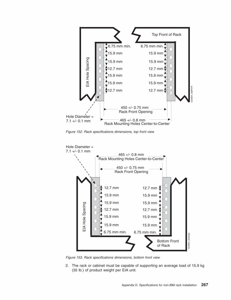
2. The rack or cabinet must be capable of supporting an average load of 15.9 kg(35 lb.) of product weight per EIA unit.
Top Front of Rack
EIA
Hol
eS
paci
ng
6.75 mm min.
15.9 mm
15.9 mm
15.9 mm
15.9 mm
12.7 mm
12.7 mm
Hole Diameter =7.1 +/- 0.1 mm
450 +/- 0.75 mmRack Front Opening
465 +/- 0.8 mmRack Mounting Holes Center-to-Center
6.75 mm min.
15.9 mm
15.9 mm
12.7 mm
15.9 mm
15.9 mm
12.7 mm
noni
bm_t
opfr
ont
Figure 152. Rack specifications dimensions, top front view
Bottom Frontof Rack
EIA
Hol
eS
paci
ng
6.75 mm min.
15.9 mm
15.9 mm
15.9 mm
15.9 mm
12.7 mm
12.7 mm
Hole Diameter =7.1 +/- 0.1 mm
450 +/- 0.75 mmRack Front Opening
465 +/- 0.8 mmRack Mounting Holes Center-to-Center
6.75 mm min.
15.9 mm
15.9 mm
12.7 mm
15.9 mm
15.9 mm
12.7 mmno
nibm
_bot
view
Figure 153. Rack specifications dimensions, bottom front view
Appendix D. Specifications for non-IBM rack installation 267
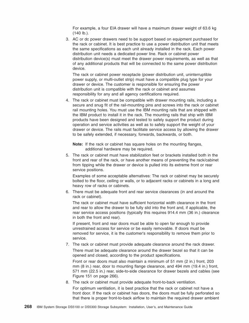
For example, a four EIA drawer will have a maximum drawer weight of 63.6 kg(140 lb.).
3. AC or dc power drawers need to be support based on equipment purchased forthe rack or cabinet. It is best practice to use a power distribution unit that meetsthe same specifications as each unit already installed in the rack. Each powerdistribution unit needs a dedicated power line. Rack or cabinet powerdistribution device(s) must meet the drawer power requirements, as well as thatof any additional products that will be connected to the same power distributiondevice.
The rack or cabinet power receptacle (power distribution unit, uninterruptiblepower supply, or multi-outlet strip) must have a compatible plug type for yourdrawer or device. The customer is responsible for ensuring the powerdistribution unit is compatible with the rack or cabinet and assumesresponsibility for any and all agency certifications required.
4. The rack or cabinet must be compatible with drawer mounting rails, including asecure and snug fit of the rail-mounting pins and screws into the rack or cabinetrail mounting holes. You must use the IBM mounting rails that are shipped withthe IBM product to install it in the rack. The mounting rails that ship with IBMproducts have been designed and tested to safely support the product duringoperation and service activities as well as to safely support the weight of yourdrawer or device. The rails must facilitate service access by allowing the drawerto be safely extended, if necessary, forwards, backwards, or both.
Note: If the rack or cabinet has square holes on the mounting flanges,additional hardware may be required.
5. The rack or cabinet must have stabilization feet or brackets installed both in thefront and rear of the rack, or have another means of preventing the rack/cabinetfrom tipping while the drawer or device is pulled into its extreme front or rearservice positions.
Examples of some acceptable alternatives: The rack or cabinet may be securelybolted to the floor, ceiling or walls, or to adjacent racks or cabinets in a long andheavy row of racks or cabinets.
6. There must be adequate front and rear service clearances (in and around therack or cabinet).
The rack or cabinet must have sufficient horizontal width clearance in the frontand rear to allow the drawer to be fully slid into the front and, if applicable, therear service access positions (typically this requires 914.4 mm (36 in.) clearancein both the front and rear).
If present, front and rear doors must be able to open far enough to provideunrestrained access for service or be easily removable. If doors must beremoved for service, it is the customer's responsibility to remove them prior toservice.
7. The rack or cabinet must provide adequate clearance around the rack drawer.
There must be adequate clearance around the drawer bezel so that it can beopened and closed, according to the product specifications.
Front or rear doors must also maintain a minimum of 51 mm (2 in.) front, 203mm (8 in.) rear, door to mounting flange clearance, and 494 mm (19.4 in.) front,571 mm (22.5 in.) rear, side-to-side clearance for drawer bezels and cables (seeFigure 151 on page 266).
8. The rack or cabinet must provide adequate front-to-back ventilation.
For optimum ventilation, it is best practice that the rack or cabinet not have afront door. If the rack or cabinet has doors, the doors must be fully perforated sothat there is proper front-to-back airflow to maintain the required drawer ambient
268 IBM System Storage DS5100 or DS5300 Storage Subsystem: Installation, User’s, and Maintenance Guide

inlet temperature as specified in the server specifications. The perforationsshould yield at least 34 percent minimum open area per square inch.
Appendix D. Specifications for non-IBM rack installation 269

270 IBM System Storage DS5100 or DS5300 Storage Subsystem: Installation, User’s, and Maintenance Guide

Appendix E. Power cords
For your safety, IBM provides a power cord with a grounded attachment plug to usewith this IBM product. To avoid electrical shock, always use the power cord andplug with a properly grounded outlet.
IBM power cords used in the United States and Canada are listed by Underwriter'sLaboratories (UL) and certified by the Canadian Standards Association (CSA).
For units intended to be operated at 115 volts: Use a UL-listed and CSA-certifiedcord set consisting of a minimum 18 AWG, Type SVT or SJT, three-conductor cord,a maximum of 15 feet in length and a parallel blade, grounding-type attachmentplug rated 15 amperes, 125 volts.
For units intended to be operated at 230 volts (U.S. use): Use a UL-listed andCSA-certified cord set consisting of a minimum 18 AWG, Type SVT or SJT,three-conductor cord, a maximum of 15 feet in length and a tandem blade,grounding-type attachment plug rated 15 amperes, 250 volts.
For units intended to be operated at 230 volts (outside the U.S.): Use a cord setwith a grounding-type attachment plug. The cord set should have the appropriatesafety approvals for the country in which the equipment will be installed.
IBM power cords for a specific country or region are usually available only in thatcountry or region.
IBM powercord partnumber
Cordspecifics Used in these countries or regions
13F9940 250V/10A2.8M
Australia, Fiji, Kiribati, Nauru, New Zealand, Papua NewGuinea
39Y7917 250V/10A2.8M
Afghanistan, Albania, Algeria, Andorra, Angola, Armenia,Austria, Azerbaijan, Belarus, Belgium, Benin, Bosnia andHerzegovina, Bulgaria, Burkina Faso, Burundi, Cambodia,Cameroon, Cape Verde, Central African Republic, Chad,Comoros, Congo (Democratic Republic of), Congo (Republicof), Cote D'Ivoire (Ivory Coast), Croatia (Republic of), CzechRep, Dahomey, Djibouti, Egypt, Equatorial Guinea, Eritrea,Estonia, Ethiopia, Finland, France, French Guyana, FrenchPolynesia, Gabon, Georgia, Germany, Greece, Guadeloupe,Guinea, Guinea Bissau, Hungary, Iceland, Indonesia, Iran,Kazakhstan, Kyrgyzstan, Laos (Peoples DemocraticRepublic of), Latvia, Lebanon, Lithuania, Luxembourg,Macedonia (former Yugoslav Republic of), Madagascar, Mali,Martinique, Mauritania, Mauritius, Mayotte, Moldova(Republic of), Monaco, Mongolia, Morocco, Mozambique,Netherlands, New Caledonia, Niger, Norway, Poland,Portugal, Reunion, Romania, Russian Federation Rwanda,Sao Tome and Principe, Saudi Arabia, Senegal, Serbia,Slovakia, Slovenia (Republic of), Somalia, Spain, Suriname,Sweden, Syrian Arab Republic, Tajikistan, Tahiti, Togo,Tunisia, Turkey, Turkmenistan, Ukraine, Upper Volta,Uzbekistan, Vanuatu, Vietnam, Wallis and Futuna,Yugoslavia (Federal Republic of), Zaire
39Y7918 250V/10A2.8M
Denmark
© Copyright IBM Corp. 2008, 2012 271
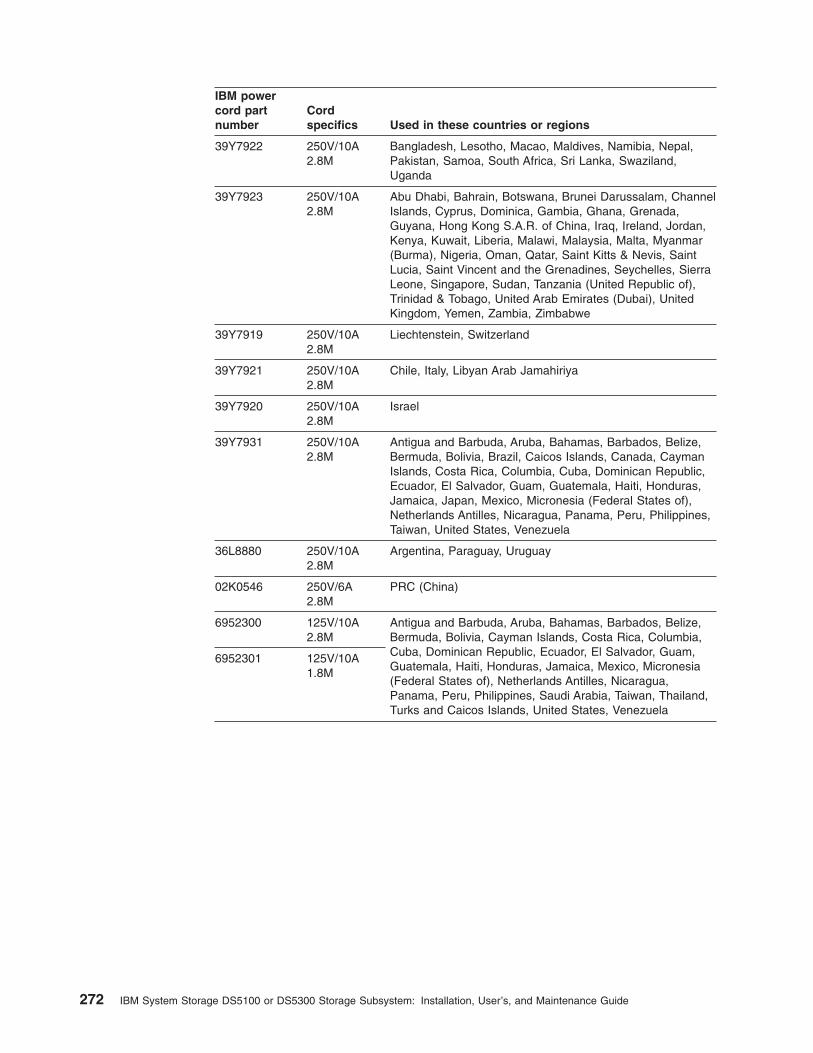
IBM powercord partnumber
Cordspecifics Used in these countries or regions
39Y7922 250V/10A2.8M
Bangladesh, Lesotho, Macao, Maldives, Namibia, Nepal,Pakistan, Samoa, South Africa, Sri Lanka, Swaziland,Uganda
39Y7923 250V/10A2.8M
Abu Dhabi, Bahrain, Botswana, Brunei Darussalam, ChannelIslands, Cyprus, Dominica, Gambia, Ghana, Grenada,Guyana, Hong Kong S.A.R. of China, Iraq, Ireland, Jordan,Kenya, Kuwait, Liberia, Malawi, Malaysia, Malta, Myanmar(Burma), Nigeria, Oman, Qatar, Saint Kitts & Nevis, SaintLucia, Saint Vincent and the Grenadines, Seychelles, SierraLeone, Singapore, Sudan, Tanzania (United Republic of),Trinidad & Tobago, United Arab Emirates (Dubai), UnitedKingdom, Yemen, Zambia, Zimbabwe
39Y7919 250V/10A2.8M
Liechtenstein, Switzerland
39Y7921 250V/10A2.8M
Chile, Italy, Libyan Arab Jamahiriya
39Y7920 250V/10A2.8M
Israel
39Y7931 250V/10A2.8M
Antigua and Barbuda, Aruba, Bahamas, Barbados, Belize,Bermuda, Bolivia, Brazil, Caicos Islands, Canada, CaymanIslands, Costa Rica, Columbia, Cuba, Dominican Republic,Ecuador, El Salvador, Guam, Guatemala, Haiti, Honduras,Jamaica, Japan, Mexico, Micronesia (Federal States of),Netherlands Antilles, Nicaragua, Panama, Peru, Philippines,Taiwan, United States, Venezuela
36L8880 250V/10A2.8M
Argentina, Paraguay, Uruguay
02K0546 250V/6A2.8M
PRC (China)
6952300 125V/10A2.8M
Antigua and Barbuda, Aruba, Bahamas, Barbados, Belize,Bermuda, Bolivia, Cayman Islands, Costa Rica, Columbia,Cuba, Dominican Republic, Ecuador, El Salvador, Guam,Guatemala, Haiti, Honduras, Jamaica, Mexico, Micronesia(Federal States of), Netherlands Antilles, Nicaragua,Panama, Peru, Philippines, Saudi Arabia, Taiwan, Thailand,Turks and Caicos Islands, United States, Venezuela
6952301 125V/10A1.8M
272 IBM System Storage DS5100 or DS5300 Storage Subsystem: Installation, User’s, and Maintenance Guide

Appendix F. Accessibility
This section provides information about alternate keyboard navigation, which is aDS Storage Manager accessibility feature. Accessibility features help a user whohas a physical disability, such as restricted mobility or limited vision, to use softwareproducts successfully.
By using the alternate keyboard operations that are described in this section, youcan use keys or key combinations to perform Storage Manager tasks and initiatemany menu actions that can also be done with a mouse.
Note: In addition to the keyboard operations that are described in this section, theDS Storage Manager version 9.14 - 10.10 (and later) software installation packagesfor Windows include a screen reader software interface.
To enable the screen reader, select Custom Installation when using the installationwizard to install Storage Manager 9.14 - 10.10 (or later) on a Windowshost/management station. Then, in the Select Product Features window, selectJava Access Bridge, in addition to the other required host software components.
Table 78 defines the keyboard operations that enable you to navigate, select, oractivate user interface components. The following terms are used in the table:
v Navigate means to move the input focus from one user interface component toanother.
v Select means to choose one or more components, typically for a subsequentaction.
v Activate means to carry out the action of a particular component.
Note: In general, navigation between components requires the following keys:
v Tab - Moves keyboard focus to the next component or to the first memberof the next group of components
v Shift-Tab - Moves keyboard focus to the previous component or to thefirst component in the previous group of components
v Arrow keys - Move keyboard focus within the individual components of agroup of components
Table 78. DS4000 Storage Manager alternate keyboard operations
Short cut Action
F1 Open the Help.
F10 Move keyboard focus to main menu bar and post firstmenu; use the arrow keys to navigate through theavailable options.
Alt+F4 Close the management window.
Alt+F6 Move keyboard focus between dialogs (non-modal) andbetween management windows.
© Copyright IBM Corp. 2008, 2012 273

Table 78. DS4000 Storage Manager alternate keyboard operations (continued)
Short cut Action
Alt+ underlined letter Access menu items, buttons, and other interfacecomponents by using the keys associated with theunderlined letters.
For the menu options, select the Alt + underlined lettercombination to access a main menu, and then select theunderlined letter to access the individual menu item.
For other interface components, use the Alt + underlinedletter combination.
Ctrl+F1 Display or conceal a tool tip when keyboard focus is onthe toolbar.
Spacebar Select an item or activate a hyperlink.
Ctrl+Spacebar(Contiguous/Non-contiguous)AMW Logical/Physical View
Select multiple drives in the Physical View.
To select multiple drives, select one drive by pressingSpacebar, and then press Tab to switch focus to the nextdrive you want to select; press Ctrl+Spacebar to selectthe drive.
If you press Spacebar alone when multiple drives areselected then all selections are removed.
Use the Ctrl+Spacebar combination to deselect a drivewhen multiple drives are selected.
This behavior is the same for contiguous andnon-contiguous selection of drives.
End, Page Down Move keyboard focus to the last item in the list.
Esc Close the current dialog. Does not require keyboardfocus.
Home, Page Up Move keyboard focus to the first item in the list.
Shift+Tab Move keyboard focus through components in the reversedirection.
Ctrl+Tab Move keyboard focus from a table to the next userinterface component.
Tab Navigate keyboard focus between components or selecta hyperlink.
Down arrow Move keyboard focus down one item in the list.
Left arrow Move keyboard focus to the left.
Right arrow Move keyboard focus to the right.
Up arrow Move keyboard focus up one item in the list.
274 IBM System Storage DS5100 or DS5300 Storage Subsystem: Installation, User’s, and Maintenance Guide

Notices
This information was developed for products and services offered in the U.S.A.
IBM may not offer the products, services, or features discussed in this document inother countries. Consult your local IBM representative for information on theproducts and services currently available in your area. Any reference to an IBMproduct, program, or service is not intended to state or imply that only that IBMproduct, program, or service may be used. Any functionally equivalent product,program, or service that does not infringe any IBM intellectual property right may beused instead. However, it is the user's responsibility to evaluate and verify theoperation of any non-IBM product, program, or service.
IBM may have patents or pending patent applications covering subject matterdescribed in this document. The furnishing of this document does not grant you anylicense to these patents. You can send license inquiries, in writing, to:
IBM Director of LicensingIBM CorporationNorth Castle DriveArmonk, NY 10504-1785U.S.A.
The following paragraph does not apply to the United Kingdom or any other countrywhere such provisions are inconsistent with local law: INTERNATIONAL BUSINESSMACHINES CORPORATION PROVIDES THIS PUBLICATION "AS IS" WITHOUTWARRANTY OF ANY KIND, EITHER EXPRESS OR IMPLIED, INCLUDING, BUTNOT LIMITED TO, THE IMPLIED WARRANTIES OF NON-INFRINGEMENT,MERCHANTABILITY OR FITNESS FOR A PARTICULAR PURPOSE. Some statesdo not allow disclaimer of express or implied warranties in certain transactions,therefore, this statement may not apply to you.
This information could include technical inaccuracies or typographical errors.Changes are periodically made to the information herein; these changes will beincorporated in new editions of the publication. IBM may make improvements and/orchanges in the product(s) and/or the program(s) described in this publication at anytime without notice.
Any references in this information to non-IBM Web sites are provided forconvenience only and do not in any manner serve as an endorsement of thoseWeb sites. The materials at those Web sites are not part of the materials for thisIBM product and use of those Web sites is at your own risk.
IBM may use or distribute any of the information you supply in any way it believesappropriate without incurring any obligation to you.
Any performance data contained herein was determined in a controlledenvironment. Therefore, the results obtained in other operating environments mayvary significantly. Some measurements may have been made on development-levelsystems and there is no guarantee that these measurements will be the same ongenerally available systems. Furthermore, some measurements may have beenestimated through extrapolation. Actual results may vary. Users of this documentshould verify the applicable data for their specific environment.
© Copyright IBM Corp. 2008, 2012 275

Information concerning non-IBM products was obtained from the suppliers of thoseproducts, their published announcements or other publicly available sources. IBMhas not tested those products and cannot confirm the accuracy of performance,compatibility or any other claims related to non-IBM products. Questions on thecapabilities of non-IBM products should be addressed to the suppliers of thoseproducts.
All statements regarding IBM's future direction or intent are subject to change orwithdrawal without notice, and represent goals and objectives only.
All IBM prices shown are IBM's suggested retail prices, are current and are subjectto change without notice. Dealer prices may vary.
This information is for planning purposes only. The information herein is subject tochange before the products described become available.
This information contains examples of data and reports used in daily businessoperations. To illustrate them as completely as possible, the examples include thenames of individuals, companies, brands, and products. All of these names arefictitious and any similarity to the names and addresses used by an actual businessenterprise is entirely coincidental.
If you are viewing this information softcopy, the photographs and color illustrationsmay not appear.
TrademarksIBM, the IBM logo, and ibm.com® are trademarks or registered trademarks ofInternational Business Machines Corp., registered in many jurisdictions worldwide.Other product and service names might be trademarks of IBM or other companies.A current list of IBM trademarks is available on the web at Copyright and trademarkinformation at http://www.ibm.com/legal/copytrade.shtml.
Adobe, the Adobe logo, PostScript, and the PostScript logo are either registeredtrademarks or trademarks of Adobe Systems Incorporated in the United States,and/or other countries.
Intel, Intel logo, Intel Inside, Intel Inside logo, Intel Centrino, Intel Centrino logo,Celeron, Intel Xeon, Intel SpeedStep, Itanium, and Pentium are trademarks orregistered trademarks of Intel Corporation or its subsidiaries in the United Statesand other countries.
Linux is a registered trademark of Linus Torvalds in the United States, othercountries, or both.
Microsoft, Windows, Windows NT, and the Windows logo are trademarks ofMicrosoft Corporation in the United States, other countries, or both.
UNIX is a registered trademark of The Open Group in the United States and othercountries.
Java and all Java-based trademarks and logos are trademarks or registeredtrademarks of Oracle and/or its affiliates.
276 IBM System Storage DS5100 or DS5300 Storage Subsystem: Installation, User’s, and Maintenance Guide

Important notesProcessor speed indicates the internal clock speed of the microprocessor; otherfactors also affect application performance.
CD or DVD drive speed is the variable read rate. Actual speeds vary and are oftenless than the possible maximum.
When referring to processor storage, real and virtual storage, or channel volume,KB stands for 1024 bytes, MB stands for 1 048 576 bytes, and GB stands for1 073 741 824 bytes.
When referring to hard disk drive capacity or communications volume, MB standsfor 1 000 000 bytes, and GB stands for 1 000 000 000 bytes. Total user-accessiblecapacity can vary depending on operating environments.
Maximum internal hard disk drive capacities assume the replacement of anystandard hard disk drives and population of all hard disk drive bays with the largestcurrently supported drives that are available from IBM.
Maximum memory might require replacement of the standard memory with anoptional memory module.
IBM makes no representation or warranties regarding non-IBM products andservices that are ServerProven®, including but not limited to the implied warrantiesof merchantability and fitness for a particular purpose. These products are offeredand warranted solely by third parties.
IBM makes no representations or warranties with respect to non-IBM products.Support (if any) for the non-IBM products is provided by the third party, not IBM.
Some software might differ from its retail version (if available) and might not includeuser manuals or all program functionality.
Particulate contaminationAttention: Airborne particulates (including metal flakes or particles) and reactivegases acting alone or in combination with other environmental factors such ashumidity or temperature might pose a risk to the storage subsystem that isdescribed in this document. Risks that are posed by the presence of excessiveparticulate levels or concentrations of harmful gases include damage that mightcause the storage subsystem to malfunction or cease functioning altogether. Thisspecification sets forth limits for particulates and gases that are intended to avoidsuch damage. The limits must not be viewed or used as definitive limits, becausenumerous other factors, such as temperature or moisture content of the air, caninfluence the impact of particulates or environmental corrosives and gaseouscontaminant transfer. In the absence of specific limits that are set forth in thisdocument, you must implement practices that maintain particulate and gas levelsthat are consistent with the protection of human health and safety. If IBMdetermines that the levels of particulates or gases in your environment have causeddamage to the storage subsystem, IBM may condition provision of repair orreplacement of storage subsystem or parts on implementation of appropriateremedial measures to mitigate such environmental contamination. Implementation ofsuch remedial measures is a customer responsibility.
Notices 277

Table 79. Limits for particulates and gases
Contaminant Limits
Particulate v The room air must be continuously filtered with 40% atmospheric dustspot efficiency (MERV 9) according to ASHRAE Standard 52.21.
v Air that enters a data center must be filtered to 99.97% efficiency orgreater, using high-efficiency particulate air (HEPA) filters that meetMIL-STD-282.
v The deliquescent relative humidity of the particulate contaminationmust be more than 60%2.
v The room must be free of conductive contamination such as zincwhiskers.
Gaseous v Copper: Class G1 as per ANSI/ISA 71.04-19853
v Silver: Corrosion rate of less than 300 Å in 30 days1 ASHRAE 52.2-2008 - Method of Testing General Ventilation Air-Cleaning Devices forRemoval Efficiency by Particle Size. Atlanta: American Society of Heating, Refrigerating andAir-Conditioning Engineers, Inc.
2 The deliquescent relative humidity of particulate contamination is the relative humidity atwhich the dust absorbs enough water to become wet and promote ionic conduction.
3 ANSI/ISA-71.04-1985. Environmental conditions for process measurement and controlsystems: Airborne contaminants. Instrument Society of America, Research Triangle Park,North Carolina, U.S.A.
Documentation formatThe publications for this product are in Adobe Portable Document Format (PDF)and should be compliant with accessibility standards. If you experience difficultieswhen you use the PDF files and want to request a Web-based format or accessiblePDF document for a publication, direct your mail to the following address:
Information DevelopmentIBM Corporation205/A0153039 E. Cornwallis RoadP.O. Box 12195Research Triangle Park, North Carolina 27709-2195U.S.A.
In the request, be sure to include the publication part number and title.
When you send information to IBM, you grant IBM a nonexclusive right to use ordistribute the information in any way it believes appropriate without incurring anyobligation to you.
Electronic emission noticesThe following statements apply to this product. The statements for other productsintended for use with this product will appear in their accompanying manuals.
Federal Communications Commission (FCC) Class A StatementThis equipment has been tested and complies with the limits for a Class A digitaldevice, pursuant to Part 15 of the FCC Rules. These limits are designed to providereasonable protection against harmful interference when the equipment is operatedin a commercial environment. This equipment generates, uses, and can radiateradio frequency energy and, if not installed and used in accordance with the
278 IBM System Storage DS5100 or DS5300 Storage Subsystem: Installation, User’s, and Maintenance Guide

instruction manual, may cause harmful interference to radio communications.Operation of this equipment in a residential area is likely to cause harmfulinterference, in which case the user will be required to correct the interference athis own expense.
Properly shielded and grounded cables and connectors must be used in order tomeet FCC emission limits. IBM is not responsible for any radio or televisioninterference caused by using other than recommended cables and connectors or byunauthorized changes or modifications to this equipment. Unauthorized changes ormodifications could void the user's authority to operate the equipment.
This device complies with Part 15 of the FCC Rules. Operation is subject to thefollowing two conditions: (1) this device may not cause harmful interference, and (2)this device must accept any interference received, including interference that maycause undesired operation.
Industry Canada Class A Emission Compliance StatementThis Class A digital apparatus complies with Canadian ICES-003.
Avis de conformité à la réglementation d'Industrie CanadaCet appareil numérique de la classe A est conform à la norme NMB-003 duCanada.
Australia and New Zealand Class A StatementAttention: This is a Class A product. In a domestic environment this productmight cause radio interference in which case the user might be required to takeadequate measures.
European Union EMC Directive Conformance StatementThis product is in conformity with the protection requirements of EU CouncilDirective 2004/108/EC on the approximation of the laws of the Member Statesrelating to electromagnetic compatibility. IBM cannot accept responsibility for anyfailure to satisfy the protection requirements resulting from a non-recommendedmodification of the product, including the fitting of non-IBM option cards.
Attention: This is an EN55022 Class A product. In a domestic environment thisproduct may cause radio interference in which case the user may be required totake adequate measures.
Responsible manufacturer:International Business Machines Corp.New Orchard RoadArmonk, New York 10504Tel: 919-499-1900
European community contact:IBM Deutschland GmbHTechnical Regulations, Department M372IBM-Allee 1, 71139 Ehningen, GermanyTele: +49 7032 15 2941e-mail: [email protected]
Notices 279

Germany Electromagnetic Compatibility DirectiveDeutschsprachiger EU Hinweis:
Hinweis für Geräte der Klasse A EU-Richtlinie zur ElektromagnetischenVerträglichkeit
Dieses Produkt entspricht den Schutzanforderungen der EU-Richtlinie 2004/108/EGzur Angleichung der Rechtsvorschriften über die elektromagnetische Verträglichkeitin den EU-Mitgliedsstaaten und hält die Grenzwerte der EN 55022 Klasse A ein.
Um dieses sicherzustellen, sind die Geräte wie in den Handbüchern beschrieben zuinstallieren und zu betreiben. Des Weiteren dürfen auch nur von der IBMempfohlene Kabel angeschlossen werden. IBM übernimmt keine Verantwortung fürdie Einhaltung der Schutzanforderungen, wenn das Produkt ohne Zustimmung derIBM verändert bzw. wenn Erweiterungskomponenten von Fremdherstellern ohneEmpfehlung der IBM gesteckt/eingebaut werden.
EN 55022 Klasse A Geräte müssen mit folgendem Warnhinweis versehen werden:"Warnung: Dieses ist eine Einrichtung der Klasse A. Diese Einrichtung kann imWohnbereich Funk-Störungen verursachen; in diesem Fall kann vom Betreiberverlangt werden, angemessene Maßnahmen zu ergreifen und dafür aufzukommen."
Deutschland: Einhaltung des Gesetzes über die elektromagnetischeVerträglichkeit von Geräten
Dieses Produkt entspricht dem "Gesetz über die elektromagnetische Verträglichkeitvon Geräten (EMVG)". Dies ist die Umsetzung der EU-Richtlinie 2004/108/EG inder Bundesrepublik Deutschland.
Zulassungsbescheinigung laut dem Deutschen Gesetz über dieelektromagnetische Verträglichkeit von Geräten (EMVG) (bzw. der EMC EGRichtlinie 2004/108/EG) für Geräte der Klasse A
Dieses Gerät ist berechtigt, in Übereinstimmung mit dem Deutschen EMVG dasEG-Konformitätszeichen - CE - zu führen.
Verantwortlich für die Einhaltung der EMV Vorschriften ist der Hersteller:International Business Machines Corp.New Orchard RoadArmonk, New York 10504Tel: 919-499-1900
Der verantwortliche Ansprechpartner des Herstellers in der EU ist:IBM Deutschland GmbHTechnical Regulations, Abteilung M372IBM-Allee 1, 71139 Ehningen, GermanyTele: +049 7032 15 2941e-mail: [email protected]
Generelle Informationen:
Das Gerät erfüllt die Schutzanforderungen nach EN 55024 und EN 55022Klasse A.
280 IBM System Storage DS5100 or DS5300 Storage Subsystem: Installation, User’s, and Maintenance Guide

Japan Voluntary Control Council for Interference (VCCI) Class AStatement
Translation: This is a Class A product based on the standard of the VCCI Council.If this equipment is used in a domestic environment, radio interference may occur,in which case, the user may be required to take corrective actions.
Japan Electronics and Information Technology Industries Association(JEITA) Statement
Japanese Electronics and Information Technology Industries Association (JEITA)Confirmed Harmonics Guideline (products less than or equal to 20 A per phase).
Korea Communications Commission (KCC) Class A StatementPlease note that this equipment has obtained EMC registration for commercial use.In the event that it has been mistakenly sold or purchased, please exchange it forequipment certified for home use.
People's Republic of China Class A Electronic Emission Statement
jjieta
1
Notices 281

Russia Electromagnetic Interference (EMI) Class A Statement
Taiwan Class A Electronic Emission Statement
ruse
mi
282 IBM System Storage DS5100 or DS5300 Storage Subsystem: Installation, User’s, and Maintenance Guide
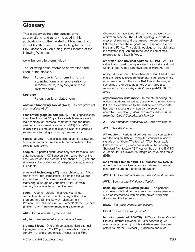
Glossary
This glossary defines the special terms,abbreviations, and acronyms used in thispublication and other related publications. If youdo not find the term you are looking for, see theIBM Glossary of Computing Terms located at thefollowing Web site:
www.ibm.com/ibm/terminology
The following cross-reference conventions areused in this glossary:
See Refers you to (a) a term that is theexpanded form of an abbreviation oracronym, or (b) a synonym or morepreferred term.
See alsoRefers you to a related term.
Abstract Windowing Toolkit (AWT). A Java graphicaluser interface (GUI).
accelerated graphics port (AGP). A bus specificationthat gives low-cost 3D graphics cards faster access tomain memory on personal computers than the usualperipheral component interconnect (PCI) bus. AGPreduces the overall cost of creating high-end graphicssubsystems by using existing system memory.
access volume. A special logical drive that allows thehost-agent to communicate with the controllers in thestorage subsystem.
adapter. A printed circuit assembly that transmits userdata input/output (I/O) between the internal bus of thehost system and the external fibre-channel (FC) link andvice versa. Also called an I/O adapter, host adapter, orFC adapter.
advanced technology (AT) bus architecture. A busstandard for IBM compatibles. It extends the XT busarchitecture to 16 bits and also allows for busmastering, although only the first 16 MB of mainmemory are available for direct access.
agent. A server program that receives virtualconnections from the network manager (the clientprogram) in a Simple Network ManagementProtocol-Transmission Control Protocol/Internet Protocol(SNMP-TCP/IP) network-managing environment.
AGP. See accelerated graphics port.
AL_PA. See arbitrated loop physical address.
arbitrated loop. One of three existing fibre-channeltopologies, in which 2 - 126 ports are interconnectedserially in a single loop circuit. Access to the Fibre
Channel Arbitrated Loop (FC-AL) is controlled by anarbitration scheme. The FC-AL topology supports allclasses of service and guarantees in-order delivery ofFC frames when the originator and responder are onthe same FC-AL. The default topology for the disk arrayis arbitrated loop. An arbitrated loop is sometimesreferred to as a Stealth Mode.
arbitrated loop physical address (AL_PA). An 8-bitvalue that is used to uniquely identify an individual portwithin a loop. A loop can have one or more AL_PAs.
array. A collection of fibre-channel or SATA hard drivesthat are logically grouped together. All the drives in thearray are assigned the same RAID level. An array issometimes referred to as a "RAID set." See alsoredundant array of independent disks (RAID), RAIDlevel.
asynchronous write mode. In remote mirroring, anoption that allows the primary controller to return a writeI/O request completion to the host server before datahas been successfully written by the secondarycontroller. See also synchronous write mode, remotemirroring, Global Copy,Global Mirroring.
AT. See advanced technology (AT) bus architecture.
ATA. See AT-attached.
AT-attached. Peripheral devices that are compatiblewith the original IBM AT computer standard in whichsignals on a 40-pin AT-attached (ATA) ribbon cablefollowed the timings and constraints of the IndustryStandard Architecture (ISA) system bus on the IBM PCAT computer. Equivalent to integrated drive electronics(IDE).
auto-volume transfer/auto-disk transfer (AVT/ADT).A function that provides automatic failover in case ofcontroller failure on a storage subsystem.
AVT/ADT. See auto-volume transfer/auto-disk transfer.
AWT. See Abstract Windowing Toolkit.
basic input/output system (BIOS). The personalcomputer code that controls basic hardware operations,such as interactions with diskette drives, hard diskdrives, and the keyboard.
BIOS. See basic input/output system.
BOOTP. See bootstrap protocol.
bootstrap protocol (BOOTP). In Transmission ControlProtocol/Internet Protocol (TCP/IP) networking, analternative protocol by which a diskless machine canobtain its Internet Protocol (IP) address and such
© Copyright IBM Corp. 2008, 2012 283

configuration information as IP addresses of variousservers from a BOOTP server.
bridge. A storage area network (SAN) device thatprovides physical and transport conversion, such asfibre channel to small computer system interface (SCSI)bridge.
bridge group. A bridge and the collection of devicesconnected to it.
broadcast. The simultaneous transmission of data tomore than one destination.
cathode ray tube (CRT). A display device in whichcontrolled electron beams are used to displayalphanumeric or graphical data on anelectroluminescent screen.
client. A computer system or process that requests aservice of another computer system or process that istypically referred to as a server. Multiple clients canshare access to a common server.
command. A statement used to initiate an action orstart a service. A command consists of the commandname abbreviation, and its parameters and flags ifapplicable. A command can be issued by typing it on acommand line or selecting it from a menu.
community string. The name of a communitycontained in each Simple Network ManagementProtocol (SNMP) message.
concurrent download. A method of downloading andinstalling firmware that does not require the user to stopI/O to the controllers during the process.
CRC. See cyclic redundancy check.
CRT. See cathode ray tube.
CRU. See customer replaceable unit.
customer replaceable unit (CRU). An assembly orpart that a customer can replace in its entirety when anyof its components fail. Contrast with field replaceableunit (FRU).
cyclic redundancy check (CRC). (1) A redundancycheck in which the check key is generated by a cyclicalgorithm. (2) An error detection technique performed atboth the sending and receiving stations.
dac. See disk array controller.
dar. See disk array router.
DASD. See direct access storage device.
data striping. See striping.
default host group. A logical collection of discoveredhost ports, defined host computers, and defined hostgroups in the storage-partition topology that fulfill thefollowing requirements:
v Are not involved in specific logical drive-to-LUNmappings
v Share access to logical drives with default logicaldrive-to-LUN mappings
device type. Identifier used to place devices in thephysical map, such as the switch, hub, or storage.
DHCP. See Dynamic Host Configuration Protocol.
direct access storage device (DASD). A device inwhich access time is effectively independent of thelocation of the data. Information is entered and retrievedwithout reference to previously accessed data. (Forexample, a disk drive is a DASD, in contrast with a tapedrive, which stores data as a linear sequence.) DASDsinclude both fixed and removable storage devices.
direct memory access (DMA). The transfer of databetween memory and an input/output (I/O) devicewithout processor intervention.
disk array controller (dac). A disk array controllerdevice that represents the two controllers of an array.See also disk array router.
disk array router (dar). A disk array router thatrepresents an entire array, including current anddeferred paths to all logical unit numbers (LUNs) (hdiskson AIX). See also disk array controller.
DMA. See direct memory access.
domain. The most significant byte in the node port(N_port) identifier for the fibre-channel (FC) device. It isnot used in the fibre channel-small computer systeminterface (FC-SCSI) hardware path ID. It is required tobe the same for all SCSI targets logically connected toan FC adapter.
drive channels. The DS4200, DS4700, DS4800,DS5100, and DS5300 subsystems use dual-port drivechannels that, from the physical point of view, areconnected in the same way as two drive loops.However, from the point of view of the number of drivesand enclosures, they are treated as a single drive loopinstead of two different drive loops. A group of storageexpansion enclosures are connected to the storagesubsystems using a drive channel from each controller.This pair of drive channels is referred to as a redundantdrive channel pair.
drive loops. A drive loop consists of one channel fromeach controller combined to form one pair of redundantdrive channels or a redundant drive loop. Each driveloop is associated with two ports. Drive loops are morecommonly referred to as drive channels. See drivechannels.
284 IBM System Storage DS5100 or DS5300 Storage Subsystem: Installation, User’s, and Maintenance Guide

DRAM. See dynamic random access memory.
Dynamic Host Configuration Protocol (DHCP). Aprotocol defined by the Internet Engineering Task Forcethat is used for dynamically assigning Internet Protocol(IP) addresses to computers in a network.
dynamic random access memory (DRAM). Astorage in which the cells require repetitive applicationof control signals to retain stored data.
ECC. See error correction coding.
EEPROM. See electrically erasable programmableread-only memory.
EISA. See Extended Industry Standard Architecture.
electrically erasable programmable read-onlymemory (EEPROM). A type of memory chip which canretain its contents without consistent electrical power.Unlike the PROM which can be programmed only once,the EEPROM can be erased electrically. Because it canonly be reprogrammed a limited number of times beforeit wears out, it is appropriate for storing small amountsof data that are changed infrequently.
electrostatic discharge (ESD). The flow of currentthat results when objects that have a static chargecome into close enough proximity to discharge.
environmental service module (ESM) canister. Acomponent in a storage expansion enclosure thatmonitors the environmental condition of the componentsin that enclosure. Not all storage subsystems have ESMcanisters.
E_port. See expansion port.
error correction coding (ECC). A method forencoding data so that transmission errors can bedetected and corrected by examining the data on thereceiving end. Most ECCs are characterized by themaximum number of errors they can detect and correct.
ESD. See electrostatic discharge.
ESM canister. See environmental service modulecanister.
automatic ESM firmware synchronization. Whenyou install a new ESM into an existing storageexpansion enclosure in a DS4000 storage subsystemthat supports automatic ESM firmware synchronization,the firmware in the new ESM is automaticallysynchronized with the firmware in the existing ESM.
EXP. See storage expansion enclosure.
expansion port (E_port). A port that connects theswitches for two fabrics.
Extended Industry Standard Architecture (EISA). Abus standard for IBM compatibles that extends the
Industry Standard Architecture (ISA) bus architecture to32 bits and allows more than one central processingunit (CPU) to share the bus. See also Industry StandardArchitecture.
fabric. A fibre channel entity which interconnects andfacilitates logins of N_ports attached to it. The fabric isresponsible for routing frames between source anddestination N_ports using address information in theframe header. A fabric can be as simple as apoint-to-point channel between two N-ports, or ascomplex as a frame-routing switch that provides multipleand redundant internal pathways within the fabricbetween F_ports.
fabric port (F_port). In a fabric, an access point forconnecting a user's N_port. An F_port facilitates N_portlogins to the fabric from nodes connected to the fabric.An F_port is addressable by the N_port connected to it.See also fabric.
FC. See Fibre Channel.
FC-AL. See arbitrated loop.
feature enable identifier. A unique identifier for thestorage subsystem, which is used in the process ofgenerating a premium feature key. See also premiumfeature key.
Fibre Channel (FC). A set of standards for a serialinput/output (I/O) bus capable of transferring databetween two ports at up to 100 Mbps, with standardsproposals to go to higher speeds. FC supportspoint-to-point, arbitrated loop, and switched topologies.
Fibre Channel Arbitrated Loop (FC-AL). Seearbitrated loop.
Fibre Channel Protocol (FCP) for small computersystem interface (SCSI). A high-level fibre-channelmapping layer (FC-4) that uses lower-level fibre-channel(FC-PH) services to transmit SCSI commands, data,and status information between a SCSI initiator and aSCSI target across the FC link by using FC frame andsequence formats.
field replaceable unit (FRU). An assembly that isreplaced in its entirety when any one of its componentsfails. In some cases, a field replaceable unit mightcontain other field replaceable units. Contrast withcustomer replaceable unit (CRU).
FlashCopy. A premium feature for DS4000 that canmake an instantaneous copy of the data in a volume.
F_port. See fabric port.
FRU. See field replaceable unit.
GBIC. See gigabit interface converter
gigabit interface converter (GBIC). A transceiver thatperforms serial, optical-to-electrical, and
Glossary 285

electrical-to-optical signal conversions for high-speednetworking. A GBIC can be hot swapped. See alsosmall form-factor pluggable.
Global Copy. Refers to a remote logical drive mirrorpair that is set up using asynchronous write modewithout the write consistency group option. This is alsoreferred to as "Asynchronous Mirroring withoutConsistency Group." Global Copy does not ensure thatwrite requests to multiple primary logical drives arecarried out in the same order on the secondary logicaldrives as they are on the primary logical drives. If it iscritical that writes to the primary logical drives arecarried out in the same order in the appropriatesecondary logical drives, Global Mirroring should beused instead of Global Copy. See also asynchronouswrite mode, Global Mirroring, remote mirroring, MetroMirroring.
Global Mirroring. Refers to a remote logical drivemirror pair that is set up using asynchronous write modewith the write consistency group option. This is alsoreferred to as "Asynchronous Mirroring with ConsistencyGroup." Global Mirroring ensures that write requests tomultiple primary logical drives are carried out in thesame order on the secondary logical drives as they areon the primary logical drives, preventing data on thesecondary logical drives from becoming inconsistentwith the data on the primary logical drives. See alsoasynchronous write mode, Global Copy, remotemirroring, Metro Mirroring.
graphical user interface (GUI). A type of computerinterface that presents a visual metaphor of a real-worldscene, often of a desktop, by combining high-resolutiongraphics, pointing devices, menu bars and other menus,overlapping windows, icons, and the object-actionrelationship.
GUI. See graphical user interface.
HBA. See host bus adapter.
hdisk. An AIX term representing a logical unit number(LUN) on an array.
heterogeneous host environment. A host system inwhich multiple host servers, which use differentoperating systems with their own unique disk storagesubsystem settings, connect to the same DS4000storage subsystem at the same time. See also host.
host. A system that is directly attached to the storagesubsystem through a fibre-channel input/output (I/O)path. This system is used to serve data (typically in theform of files) from the storage subsystem. A system canbe both a storage management station and a hostsimultaneously.
host bus adapter (HBA). An interface between thefibre-channel network and a workstation or server.
host computer. See host.
host group. An entity in the storage partition topologythat defines a logical collection of host computers thatrequire shared access to one or more logical drives.
host port. Ports that physically reside on the hostadapters and are automatically discovered by theDS4000 Storage Manager software. To give a hostcomputer access to a partition, its associated host portsmust be defined.
hot swap. To replace a hardware component withoutturning off the system.
hub. In a network, a point at which circuits are eitherconnected or switched. For example, in a star network,the hub is the central node; in a star/ring network, it isthe location of wiring concentrators.
IBMSAN driver. The device driver that is used in aNovell NetWare environment to provide multipathinput/output (I/O) support to the storage controller.
IC. See integrated circuit.
IDE. See integrated drive electronics.
in-band. Transmission of management protocol overthe fibre-channel transport.
Industry Standard Architecture (ISA). Unofficialname for the bus architecture of the IBM PC/XTpersonal computer. This bus design included expansionslots for plugging in various adapter boards. Earlyversions had an 8-bit data path, later expanded to 16bits. The "Extended Industry Standard Architecture"(EISA) further expanded the data path to 32 bits. Seealso Extended Industry Standard Architecture.
initial program load (IPL). The initialization procedurethat causes an operating system to commenceoperation. Also referred to as a system restart, systemstartup, and boot.
integrated circuit (IC). A microelectronicsemiconductor device that consists of manyinterconnected transistors and other components. ICsare constructed on a small rectangle cut from a siliconcrystal or other semiconductor material. The small sizeof these circuits allows high speed, low powerdissipation, and reduced manufacturing cost comparedwith board-level integration. Also known as a chip.
integrated drive electronics (IDE). A disk driveinterface based on the 16-bit IBM personal computerIndustry Standard Architecture (ISA) in which thecontroller electronics reside on the drive itself,eliminating the need for a separate adapter card. Alsoknown as an Advanced Technology AttachmentInterface (ATA).
286 IBM System Storage DS5100 or DS5300 Storage Subsystem: Installation, User’s, and Maintenance Guide

Internet Protocol (IP). A protocol that routes datathrough a network or interconnected networks. IP actsas an intermediary between the higher protocol layersand the physical network.
Internet Protocol (IP) address. The unique 32-bitaddress that specifies the location of each device orworkstation on the Internet. For example, 9.67.97.103 isan IP address.
interrupt request (IRQ). A type of input found onmany processors that causes the processor to suspendnormal processing temporarily and start running aninterrupt handler routine. Some processors have severalinterrupt request inputs that allow different priorityinterrupts.
IP. See Internet Protocol.
IPL. See initial program load.
IRQ. See interrupt request.
ISA. See Industry Standard Architecture.
Java Runtime Environment (JRE). A subset of theJava Development Kit (JDK) for end users anddevelopers who want to redistribute the Java RuntimeEnvironment (JRE). The JRE consists of the Java virtualmachine, the Java Core Classes, and supporting files.
JRE. See Java Runtime Environment.
label. A discovered or user entered property value thatis displayed underneath each device in the Physical andData Path maps.
LAN. See local area network.
LBA. See logical block address.
local area network (LAN). A computer networklocated on a user's premises within a limited geographicarea.
logical block address (LBA). The address of a logicalblock. Logical block addresses are typically used inhosts' I/O commands. The SCSI disk commandprotocol, for example, uses logical block addresses.
logical partition (LPAR). (1) A subset of a singlesystem that contains resources (processors, memory,and input/output devices). A logical partition operates asan independent system. If hardware requirements aremet, multiple logical partitions can exist within a system.(2) A fixed-size portion of a logical volume. A logicalpartition is the same size as the physical partitions in itsvolume group. Unless the logical volume of which it is apart is mirrored, each logical partition corresponds to,and its contents are stored on, a single physicalpartition. (3) One to three physical partitions (copies).The number of logical partitions within a logical volumeis variable.
logical unit number (LUN). An identifier used on asmall computer system interface (SCSI) bus todistinguish among up to eight devices (logical units) withthe same SCSI ID.
loop address. The unique ID of a node infibre-channel loop topology sometimes referred to as aloop ID.
loop group. A collection of storage area network(SAN) devices that are interconnected serially in asingle loop circuit.
loop port. A node port (N_port) or fabric port (F_port)that supports arbitrated loop functions associated withan arbitrated loop topology.
LPAR. See logical partition.
LUN. See logical unit number.
MAC. See medium access control.
management information base (MIB). Theinformation that is on an agent. It is an abstraction ofconfiguration and status information.
man pages. In UNIX-based operating systems, onlinedocumentation for operating system commands,subroutines, system calls, file formats, special files,stand-alone utilities, and miscellaneous facilities.Invoked by the man command.
MCA. See micro channel architecture.
media scan. A media scan is a background processthat runs on all logical drives in the storage subsystemfor which it has been enabled, providing error detectionon the drive media. The media scan process scans alllogical drive data to verify that it can be accessed, andoptionally scans the logical drive redundancyinformation.
medium access control (MAC). In local areanetworks (LANs), the sublayer of the data link controllayer that supports medium-dependent functions anduses the services of the physical layer to provideservices to the logical link control sublayer. The MACsublayer includes the method of determining when adevice has access to the transmission medium.
Metro Mirroring. This term is used to refer to aremote logical drive mirror pair which is set up withsynchronous write mode. See also remote mirroring,Global Mirroring.
MIB. See management information base.
micro channel architecture (MCA). Hardware that isused for PS/2 Model 50 computers and above toprovide better growth potential and performancecharacteristics when compared with the originalpersonal computer design.
Glossary 287

Microsoft Cluster Server (MSCS). MSCS, a featureof Windows NT Server (Enterprise Edition), supports theconnection of two servers into a cluster for higheravailability and easier manageability. MSCS canautomatically detect and recover from server orapplication failures. It can also be used to balanceserver workload and provide for planned maintenance.
mini hub. An interface card or port device thatreceives short-wave fiber channel GBICs or SFPs.These devices enable redundant fibre channelconnections from the host computers, either directly orthrough a fibre channel switch or managed hub, overoptical fiber cables to the DS4000 Storage Servercontrollers. Each DS4000 controller is responsible fortwo mini hubs. Each mini hub has two ports. Four hostports (two on each controller) provide a cluster solutionwithout use of a switch. Two host-side mini hubs areshipped as standard. See also host port, gigabitinterface converter (GBIC), small form-factor pluggable(SFP).
mirroring. A fault-tolerance technique in whichinformation on a hard disk is duplicated on additionalhard disks. See also remote mirroring.
model. The model identification that is assigned to adevice by its manufacturer.
MSCS. See Microsoft Cluster Server.
network management station (NMS). In the SimpleNetwork Management Protocol (SNMP), a station thatruns management application programs that monitorand control network elements.
NMI. See non-maskable interrupt.
NMS. See network management station.
non-maskable interrupt (NMI). A hardware interruptthat another service request cannot overrule (mask). AnNMI bypasses and takes priority over interrupt requestsgenerated by software, the keyboard, and other suchdevices and is issued to the microprocessor only indisastrous circumstances, such as severe memoryerrors or impending power failures.
node. A physical device that allows for thetransmission of data within a network.
node port (N_port). A fibre-channel defined hardwareentity that performs data communications over thefibre-channel link. It is identifiable by a unique worldwidename. It can act as an originator or a responder.
nonvolatile storage (NVS). A storage device whosecontents are not lost when power is cut off.
N_port. See node port.
NVS. See nonvolatile storage.
NVSRAM. Nonvolatile storage random accessmemory. See nonvolatile storage.
Object Data Manager (ODM). An AIX proprietarystorage mechanism for ASCII stanza files that areedited as part of configuring a drive into the kernel.
ODM. See Object Data Manager.
out-of-band. Transmission of management protocolsoutside of the fibre-channel network, typically overEthernet.
partitioning. See storage partition.
parity check. (1) A test to determine whether thenumber of ones (or zeros) in an array of binary digits isodd or even. (2) A mathematical operation on thenumerical representation of the informationcommunicated between two pieces. For example, ifparity is odd, any character represented by an evennumber has a bit added to it, making it odd, and aninformation receiver checks that each unit of informationhas an odd value.
PCI local bus. See peripheral component interconnectlocal bus.
PDF. See portable document format.
performance events. Events related to thresholds seton storage area network (SAN) performance.
peripheral component interconnect local bus (PCIlocal bus). A local bus for PCs, from Intel, thatprovides a high-speed data path between the CPU andup to 10 peripherals (video, disk, network, and so on).The PCI bus coexists in the PC with the IndustryStandard Architecture (ISA) or Extended IndustryStandard Architecture (EISA) bus. ISA and EISA boardsplug into an IA or EISA slot, while high-speed PCIcontrollers plug into a PCI slot. See also IndustryStandard Architecture, Extended Industry StandardArchitecture.
polling delay. The time in seconds betweensuccessive discovery processes during which discoveryis inactive.
port. A part of the system unit or remote controller towhich cables for external devices (such as displaystations, terminals, printers, switches, or externalstorage units) are attached. The port is an access pointfor data entry or exit. A device can contain one or moreports.
portable document format (PDF). A standardspecified by Adobe Systems, Incorporated, for theelectronic distribution of documents. PDF files arecompact; can be distributed globally by e-mail, the Web,intranets, or CD-ROM; and can be viewed with the
288 IBM System Storage DS5100 or DS5300 Storage Subsystem: Installation, User’s, and Maintenance Guide

Acrobat Reader, which is software from Adobe Systemsthat can be downloaded at no cost from the AdobeSystems home page.
premium feature key. A file that the storagesubsystem controller uses to enable an authorizedpremium feature. The file contains the feature enableidentifier of the storage subsystem for which thepremium feature is authorized, and data about thepremium feature. See also feature enable identifier.
private loop. A freestanding arbitrated loop with nofabric attachment. See also arbitrated loop.
program temporary fix (PTF). A temporary solution orbypass of a problem diagnosed by IBM in a currentunaltered release of the program.
PTF. See program temporary fix.
RAID. See redundant array of independent disks(RAID).
RAID level. An array's RAID level is a number thatrefers to the method used to achieve redundancy andfault tolerance in the array. See also array, redundantarray of independent disks (RAID).
RAID set. See array.
RAM. See random-access memory.
random-access memory (RAM). A temporary storagelocation in which the central processing unit (CPU)stores and executes its processes. Contrast with DASD.
RDAC. See redundant disk array controller.
read-only memory (ROM). Memory in which storeddata cannot be changed by the user except underspecial conditions.
recoverable virtual shared disk (RVSD). A virtualshared disk on a server node configured to providecontinuous access to data and file systems in a cluster.
redundant array of independent disks (RAID). Acollection of disk drives (array) that appears as a singlevolume to the server, which is fault tolerant through anassigned method of data striping, mirroring, or paritychecking. Each array is assigned a RAID level, which isa specific number that refers to the method used toachieve redundancy and fault tolerance. See also array,parity check, mirroring, RAID level, striping.
redundant disk array controller (RDAC). (1) Inhardware, a redundant set of controllers (eitheractive/passive or active/active). (2) In software, a layerthat manages the input/output (I/O) through the activecontroller during normal operation and transparentlyreroutes I/Os to the other controller in the redundant setif a controller or I/O path fails.
remote mirroring. Online, real-time replication of databetween storage subsystems that are maintained onseparate media. The Enhanced Remote Mirror Option isa DS4000 premium feature that provides support forremote mirroring. See also Global Mirroring, MetroMirroring.
ROM. See read-only memory.
router. A computer that determines the path ofnetwork traffic flow. The path selection is made fromseveral paths based on information obtained fromspecific protocols, algorithms that attempt to identify theshortest or best path, and other criteria such as metricsor protocol-specific destination addresses.
RVSD. See recoverable virtual shared disk.
SAI. See Storage Array Identifier.
SA Identifier. See Storage Array Identifier.
SAN. See storage area network.
SATA. See serial ATA.
scope. Defines a group of controllers by their InternetProtocol (IP) addresses. A scope must be created anddefined so that dynamic IP addresses can be assignedto controllers on the network.
SCSI. See small computer system interface.
segmented loop port (SL_port). A port that allowsdivision of a fibre-channel private loop into multiplesegments. Each segment can pass frames around asan independent loop and can connect through the fabricto other segments of the same loop.
sense data. (1) Data sent with a negative response,indicating the reason for the response. (2) Datadescribing an I/O error. Sense data is presented to ahost system in response to a sense request command.
serial ATA. The standard for a high-speed alternativeto small computer system interface (SCSI) hard drives.The SATA-1 standard is equivalent in performance to a10 000 RPM SCSI drive.
serial storage architecture (SSA). An interfacespecification from IBM in which devices are arranged ina ring topology. SSA, which is compatible with smallcomputer system interface (SCSI) devices, allowsfull-duplex packet multiplexed serial data transfers atrates of 20 Mbps in each direction.
server. A functional hardware and software unit thatdelivers shared resources to workstation client units ona computer network.
server/device events. Events that occur on the serveror a designated device that meet criteria that the usersets.
Glossary 289

SFP. See small form-factor pluggable.
SFP+. See small form-factor pluggable.
Simple Network Management Protocol (SNMP). Inthe Internet suite of protocols, a network managementprotocol that is used to monitor routers and attachednetworks. SNMP is an application layer protocol.Information on devices managed is defined and storedin the application's Management Information Base(MIB).
SL_port. See segmented loop port.
SMagent. The DS4000 Storage Manager optionalJava-based host-agent software, which can be used onMicrosoft Windows, Novell NetWare, AIX, HP-UX,Solaris, and Linux on POWER host systems to managestorage subsystems through the host fibre-channelconnection.
SMclient. The DS4000 Storage Manager clientsoftware, which is a Java-based graphical user interface(GUI) that is used to configure, manage, andtroubleshoot storage servers and storage expansionenclosures in a DS4000 storage subsystem. SMclientcan be used on a host system or on a storagemanagement station.
SMruntime. A Java compiler for the SMclient.
SMutil. The DS4000 Storage Manager utility softwarethat is used on Microsoft Windows, AIX, HP-UX, Solaris,and Linux on POWER host systems to register and mapnew logical drives to the operating system. In MicrosoftWindows, it also contains a utility to flush the cacheddata of the operating system for a particular drive beforecreating a FlashCopy.
small computer system interface (SCSI). A standardhardware interface that enables a variety of peripheraldevices to communicate with one another.
small form-factor pluggable (SFP or SFP+). Anoptical transceiver that is used to convert signalsbetween optical fiber cables and switches. An SFP issmaller than a gigabit interface converter (GBIC). AnSFP+ is an enhanced standard SFP. See also gigabitinterface converter.
SNMP. See Simple Network Management Protocol andSNMPv1.
SNMP trap event. (1) (2) An event notification sent bythe SNMP agent that identifies conditions, such asthresholds, that exceed a predetermined value. Seealso Simple Network Management Protocol.
SNMPv1. The original standard for SNMP is nowreferred to as SNMPv1, as opposed to SNMPv2, arevision of SNMP. See also Simple NetworkManagement Protocol.
SRAM. See static random access memory.
SSA. See serial storage architecture.
static random access memory (SRAM). Randomaccess memory based on the logic circuit know asflip-flop. It is called static because it retains a value aslong as power is supplied, unlike dynamic randomaccess memory (DRAM), which must be regularlyrefreshed. It is however, still volatile, meaning that it canlose its contents when the power is turned off.
storage area network (SAN). A dedicated storagenetwork tailored to a specific environment, combiningservers, storage products, networking products,software, and services. See also fabric.
Storage Array Identifier (SAI or SA Identifier). TheStorage Array Identifier is the identification value usedby the DS4000 Storage Manager host software(SMClient) to uniquely identify each managed storageserver. The DS4000 Storage Manager SMClientprogram maintains Storage Array Identifier records ofpreviously-discovered storage servers in the hostresident file, which allows it to retain discoveryinformation in a persistent fashion.
storage expansion enclosure (EXP). A feature thatcan be connected to a system unit to provide additionalstorage and processing capacity.
storage management station. A system that is usedto manage the storage subsystem. A storagemanagement station does not need to be attached tothe storage subsystem through the fibre-channelinput/output (I/O) path.
storage partition. Storage subsystem logical drivesthat are visible to a host computer or are shared amonghost computers that are part of a host group.
storage partition topology. In the DS4000 StorageManager client, the Topology view of the Mappingswindow displays the default host group, the defined hostgroup, the host computer, and host-port nodes. Thehost port, host computer, and host group topologicalelements must be defined to grant access to hostcomputers and host groups using logical drive-to-LUNmappings.
striping. Splitting data to be written into equal blocksand writing blocks simultaneously to separate diskdrives. Striping maximizes performance to the disks.Reading the data back is also scheduled in parallel, witha block being read concurrently from each disk thenreassembled at the host.
subnet. An interconnected but independent segmentof a network that is identified by its Internet Protocol (IP)address.
290 IBM System Storage DS5100 or DS5300 Storage Subsystem: Installation, User’s, and Maintenance Guide

sweep method. A method of sending Simple NetworkManagement Protocol (SNMP) requests for informationto all the devices on a subnet by sending the request toevery device in the network.
switch. A fibre-channel device that provides fullbandwidth per port and high-speed routing of data byusing link-level addressing.
switch group. A switch and the collection of devicesconnected to it that are not in other groups.
switch zoning. See zoning.
synchronous write mode. In remote mirroring, anoption that requires the primary controller to wait for theacknowledgment of a write operation from thesecondary controller before returning a write I/O requestcompletion to the host. See also asynchronous writemode, remote mirroring, Metro Mirroring.
system name. Device name assigned by the vendor'sthird-party software.
TCP. See Transmission Control Protocol.
TCP/IP. See Transmission Control Protocol/InternetProtocol.
terminate and stay resident program (TSRprogram). A program that installs part of itself as anextension of DOS when it is executed.
topology. The physical or logical arrangement ofdevices on a network. The three fibre-channeltopologies are fabric, arbitrated loop, and point-to-point.The default topology for the disk array is arbitrated loop.
TL_port. See translated loop port.
transceiver. A device that is used to transmit andreceive data. Transceiver is an abbreviation oftransmitter-receiver.
translated loop port (TL_port). A port that connectsto a private loop and allows connectivity between theprivate loop devices and off loop devices (devices notconnected to that particular TL_port).
Transmission Control Protocol (TCP). Acommunication protocol used in the Internet and in anynetwork that follows the Internet Engineering Task Force(IETF) standards for internetwork protocol. TCPprovides a reliable host-to-host protocol between hostsin packed-switched communication networks and ininterconnected systems of such networks. It uses theInternet Protocol (IP) as the underlying protocol.
Transmission Control Protocol/Internet Protocol(TCP/IP). A set of communication protocols thatprovide peer-to-peer connectivity functions for both localand wide-area networks.
trap. In the Simple Network Management Protocol(SNMP), a message sent by a managed node (agentfunction) to a management station to report anexception condition.
trap recipient. Receiver of a forwarded SimpleNetwork Management Protocol (SNMP) trap.Specifically, a trap receiver is defined by an InternetProtocol (IP) address and port to which traps are sent.Presumably, the actual recipient is a softwareapplication running at the IP address and listening tothe port.
TSR program. See terminate and stay residentprogram.
uninterruptible power supply. A source of powerfrom a battery that is installed between a computersystem and its power source. The uninterruptible powersupply keeps the system running if a commercial powerfailure occurs, until an orderly shutdown of the systemcan be performed.
user action events. Actions that the user takes, suchas changes in the storage area network (SAN), changedsettings, and so on.
worldwide port name (WWPN). A unique identifier fora switch on local and global networks.
worldwide name (WWN). A globally unique 64-bitidentifier assigned to each fibre channel port.
WORM. See write-once read-many.
write-once read many (WORM). Any type of storagemedium to which data can be written only a single time,but can be read from any number of times. After thedata is recorded, it cannot be altered.
WWN. See worldwide name.
zoning. (1) In fibre channel environments, thegrouping of multiple ports to form a virtual, private,storage network. Ports that are members of a zone cancommunicate with each other, but are isolated fromports in other zones. (2) A function that allowssegmentation of nodes by address, name, or physicalport and is provided by fabric switches or hubs.
Glossary 291

292 IBM System Storage DS5100 or DS5300 Storage Subsystem: Installation, User’s, and Maintenance Guide

Index
Aac power recovery 32accessible documentation 278acoustical noise emission values 31airflow 30, 32alarm 162altitude ranges 29area requirements 27
Bbattery
installing 216LEDs 187replacing 187verify battery charge using client software 216
battery packreplacing 213
best practices 6board ID 165BOOTP server
sample network 16
Ccabling 49
an IBM DS5100 or DS5300 storage expansionenclosure 57
an IBM System Storage DS5100 or DS5300 56drive-side trunking configurations 73, 117Non-trunking 65storage expansion enclosures to storage
subsystem 129cabling the storage subsystem
connecting host to RAID controller 132connecting power cables 147connecting secondary interface cables 135maintaining redundancy 147to storage expansion enclosures 64
cache batterySee battery 187
cache memorycache active LED 186size of 186
circuit breakersprocedure to reset 181resetting the controller circuit breakers 181
cluster support 3, 231codes
category 239detail 239
componentscontrollers 10interconnect-battery unit 22overview 7power supply and fan units 21releasing levers 192
components (continued)replacing 189weights 28
Concepts Guide 245configuration, installing the storage subsystem 147configuring storage subsystem 136contamination, particulate and gaseous 278controller information 165controller memory 19controllers
cable connections 11drive channels 13Ethernet ports 15host channels 13overview 10replacing 193resetting the circuit breakers 181serial port 16
cooling 32copper cables 231Copy Services Guide 245customer replaceable units (FRUs)
replacing a backup battery pack 213replacing an SFP module 217replacing an SFP+ module 219replacing the interconnect-battery unit 209
Ddevice drivers
downloading latest versions xxviiiDHCP server
sample network 16diagnostic code 239diagnostic hardware
wrap-plug 231diagnostic interface port 135direct
out-of-band 137documentation
documents xxviiiDS Storage Manager 245DS4000 245DS4000-related documents 256DS4100 SATA storage subsystem 254DS4200 Express storage subsystem 253DS4300 Fibre Channel storage subsystem 252DS4400 Fibre Channel storage subsystem 251DS4500 storage subsystem 250DS5020 documents 256DS5020 storage subsystem 247DS5100 and DS5300 245DS5100 and DS5300 Storage Subsystem 246DS5100 or DS5300 storage subsystem 248, 249Web sites xxix
documentation format 278documentation inventory 5
© Copyright IBM Corp. 2008, 2012 293
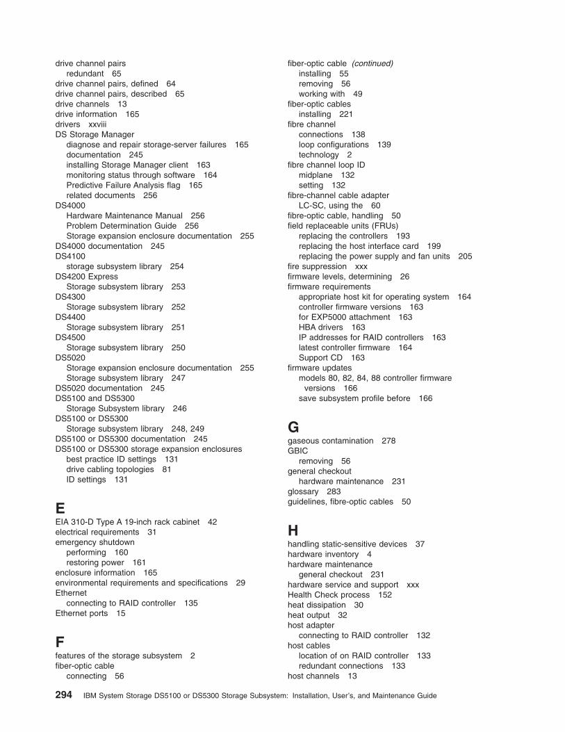
drive channel pairsredundant 65
drive channel pairs, defined 64drive channel pairs, described 65drive channels 13drive information 165drivers xxviiiDS Storage Manager
diagnose and repair storage-server failures 165documentation 245installing Storage Manager client 163monitoring status through software 164Predictive Failure Analysis flag 165related documents 256
DS4000Hardware Maintenance Manual 256Problem Determination Guide 256Storage expansion enclosure documentation 255
DS4000 documentation 245DS4100
storage subsystem library 254DS4200 Express
Storage subsystem library 253DS4300
Storage subsystem library 252DS4400
Storage subsystem library 251DS4500
Storage subsystem library 250DS5020
Storage expansion enclosure documentation 255Storage subsystem library 247
DS5020 documentation 245DS5100 and DS5300
Storage Subsystem library 246DS5100 or DS5300
Storage subsystem library 248, 249DS5100 or DS5300 documentation 245DS5100 or DS5300 storage expansion enclosures
best practice ID settings 131drive cabling topologies 81ID settings 131
EEIA 310-D Type A 19-inch rack cabinet 42electrical requirements 31emergency shutdown
performing 160restoring power 161
enclosure information 165environmental requirements and specifications 29Ethernet
connecting to RAID controller 135Ethernet ports 15
Ffeatures of the storage subsystem 2fiber-optic cable
connecting 56
fiber-optic cable (continued)installing 55removing 56working with 49
fiber-optic cablesinstalling 221
fibre channelconnections 138loop configurations 139technology 2
fibre channel loop IDmidplane 132setting 132
fibre-channel cable adapterLC-SC, using the 60
fibre-optic cable, handling 50field replaceable units (FRUs)
replacing the controllers 193replacing the host interface card 199replacing the power supply and fan units 205
fire suppression xxxfirmware levels, determining 26firmware requirements
appropriate host kit for operating system 164controller firmware versions 163for EXP5000 attachment 163HBA drivers 163IP addresses for RAID controllers 163latest controller firmware 164Support CD 163
firmware updatesmodels 80, 82, 84, 88 controller firmware
versions 166save subsystem profile before 166
Ggaseous contamination 278GBIC
removing 56general checkout
hardware maintenance 231glossary 283guidelines, fibre-optic cables 50
Hhandling static-sensitive devices 37hardware inventory 4hardware maintenance
general checkout 231hardware service and support xxxHealth Check process 152heat dissipation 30heat output 32host adapter
connecting to RAID controller 132host cables
location of on RAID controller 133redundant connections 133
host channels 13
294 IBM System Storage DS5100 or DS5300 Storage Subsystem: Installation, User’s, and Maintenance Guide

host interface cardreplacing 199
host software kits 4host-agent
in-band 136hot-swap procedures 189hub
See managed hub 133
IIBM Safety Information 256IBM Storage System
replacing a controller 193IBM System Storage
heat output, airflow, and cooling 32preparing the rack cabinet 39site preparation 39
IBM System Storage DS5100 or DS5300audible alarm 162best practices 6cabling the 49cache memory and cache battery 186checking the LEDs 167components 7connecting power cables 147controllers 10diagnostic hardware 231dimensions 27DS5100 or DS5300 and one storage expansion
enclosure 84electrical requirements 31emergency shutdown 160environmental requirements and specifications 29features 2fibre channel connections 138front bezel 154front bezel LEDs 168hardware maintenance 231identification numbers 257installation 44
needed tools 38installation overview 35installing into a rack cabinet 35installing SFP modules 51installing SFP+ modules 51installing the configuration 147installing the DS5100 or DS5300 on the support
rails 45installing the support rails 40interconnect-battery unit 22interconnect-battery unit LEDs 176introduction 1inventory checklist 4operating 151overheated power supply and fan unit recovery 179parts list 238power supply and fan unit LEDs 175power supply and fan units 21preparing for installation 37RAID controller LEDs 169
IBM System Storage DS5100 or DS5300 (continued)records 257releasing levers 192replacing components 189resetting the controller circuit breakers 181restoring power after emergency shutdown 161restoring power after over-temperature
shutdown 161restoring power after unexpected shutdown 160SFP modules 24SFP+ modules 25solving problems 231specifications 27storage expansion enclosure cabling topologies 81storage subsystem ports and controllers 81troubleshooting 166turning off 157turning on 155unpacking the 38, 43weight 28
IBM System Storage Productivity Center xxviiiinstallation
installing the DS5100 or DS5300 on the supportrails 45
into a rack cabinet 35overview 35performing 44preparing for 37preparing the rack cabinet 39site preparation 39
rack cabinet 37support rails 40
interconnect-battery unitbattery packs 187installing 212LEDs 24, 176overview 22replacing 209
inventory checklist 4iSCSI
loop configurations 143
LLC-LC fibre-channel cable 57
connecting to an SFP or SFP+ module 58latches and lever 63overview 56protective caps 60release latches 59removing 59removing from adapter 63
LC-SC fibre-channel cable adapterconnecting to a device 62connecting to an LC-LC fibre-channel cable 62protective caps 62removing an LC-LC fibre-channel cable 63using 60
LEDscache battery 187front bezel 168
Index 295
LEDs (continued)interconnect-battery unit 177power supply and fan unit 175RAID controller 169seven-segment numeric display 174
levers and latches 192line cord jumpers 4loop configurations
overview 139, 143redundant 139
MMAC address, recording 257managed hub
in fibre channel loop configurations 139in iSCSI loop configurations 143using to connect host to RAID controller 133
memory, cachecache active LED 186size of 186
Migration Guide 245models 1My Support 5
Nnon-IBM rack installation 263notes, important 277notices 275
static-sensitive precautions 189used in this book iii
Oover-temperature condition, shutdown 161
Pparticulate contamination 278parts list
IBM System Storage 238power cords
connecting 147DS5100 and DS5300 271
power cords and receptacles 32power off sequence, storage subsystem 157power on sequence, storage subsystem 155power redundancy 6, 151power supply and fan unit
if both units shut down, what to do 180installing 208LEDs 175recovery from overheating 179replacement procedure 206replacing 205shutdown recovery 179
power supply and fan unitsoverview 21
product ID 165
Rrack cabinet
EIA 310-D Type A 19 inch 42preparatory procedures 40rail installation 43
rack mounting templateDS5100 and DS5300 259
rack mounting template for DS5100 or DS5300 40RAID controller
cache battery 187connecting Ethernet cable to 135connecting host to 132connecting RS-232 (serial) cable 135
RAID controllersLEDs 169
records, maintaining 257Recovery Guru
controller recovery 186diagnose failed components 157overheated power supply and fan unit 180
redundant host and drive loops 139removing components
fiber-optic cable 56replacing a controller
checking online status 198installing 197removing SFPs from RAID controller 195using client software 193
replacing componentsbattery pack 213controller 193handling static-sensitive devices 189host interface card 199hot-swap procedures 189interconnect-battery unit 209multiple component failures 191overview 189power supply and fan unit 205procedure 192releasing levers 192Service Action Allowed Status LED 190SFP module 217SFP+ module 219single component failures 190
resourcesdocuments xxviiiWeb sites xxix
restoring powerafter emergency shutdown 161after unexpected shutdown 160
RS-232 serial port 16, 135
Ssafety information iiiSATA technology 2sequence codes 239serial number, recording 257seven-segment numeric display 174, 239SFP modules 24
296 IBM System Storage DS5100 or DS5300 Storage Subsystem: Installation, User’s, and Maintenance Guide

SFP modules (continued)important information 51installing 52, 221operating speeds 52removing 54replacing 54, 217working with 49
SFP+ modules 25important information 51installing 52operating speeds 52removing 54replacing 54, 219working with 49
shock and vibrations requirements 31shutdown sequence, storage subsystem 157Simple Network Management Protocol (SNMP)
traps 16small form-factor pluggable module (SFP)
connecting to an LC-LC fibre-channel cable 58installing and connecting to LC-LC cable 130port location 129removing an LC-LC cable 59
small form-factor pluggable module (SFP+)connecting to an LC-LC fibre-channel cable 58removing an LC-LC cable 59
SNMP traps 16software and firmware requirements 25software inventory 4specifications 27specifications, fibre-optic cables 50SSPC xxixSSPC (System Storage Productivity Center) xxviiistatic-sensitive devices, handling 37, 189storage area network (SAN)
technical support Web site xxixstorage expansion enclosure settings 130, 132storage expansion enclosures
cabling 76connecting to storage subsystem 64support 3, 10turning on before storage subsystem 155
Storage Managerinstalling for use with IBM System Storage
Productivity Center xxviiiStorage Manager software
where to obtain xxviiistorage manager software and hardware
compatibility 25storage subsystem configuration
saving 6storage subsystem configuration, installing 147storage subsystem management methods 136storage subsystem profile 151
saving 6submodel ID 165support notifications 5switch
technical support Web site xxixsymptom-to-FRU index 231System Storage Interoperation Center (SSIC) xxix
System Storage Productivity Center xxviiiSystem Storage Productivity Center (SSPC) xxix
Ttasks by document title 245tasks by documentation title 245temperature and humidity 29trademarks 276troubleshooting
IBM System Storage 166with Recovery Guru 167with Storage Manager client software 166
turning off the storage subsystem 157turning on the storage subsystem 155
checking normal operation 157startup 155subsystem status 157
Uupdates (product updates) 5
WWeb sites
Fix central xxixIBM publications center xxixIBM System Storage product information xxixlist xxixpremium feature activation xxixSAN support xxixSSIC xxixswitch support xxixSystem Storage Productivity Center (SSPC) xxix
wiring and power 32wrap-plug 4, 231
Index 297

298 IBM System Storage DS5100 or DS5300 Storage Subsystem: Installation, User’s, and Maintenance Guide


����
Part Number: 00Y5048
Printed in USA
GA32-0955-03
(1P)
P/N:
00Y5
048