iaea workshop on: technology and applications of
TRANSCRIPT

IAEA Workshop on:Technology and Applications of
Accelerator Driven Systems (ADS)
13 – 17 October 2003, Trieste, Italy
YACINE KADICERN, Switzerland
C European Organization for Nuclear Research 2
LECTURES OUTLINE
• LECTURE 1: Physics of Spallation and Sub-critical Devices, Fundamentals(Monday 13/10/03, 10:30 – 12:00)
• LECTURE 2: Nuclear Data & Methods for ADS Design(Monday 13/10/03, 14:00 – 15:30)
• LECTURE 3: ADS Design Exercise I & II (Tuesday 14/10/03, 14:00 – 17:30)
• LECTURE 4: ADS Design Examples with the EA-MC Code Package(Thursday 16/10/03, 10:30 – 12:00)
• LECTURE 5: ADS Design Exercise III & IV (Thursday 16/10/03, 14:00 – 17:30)

ADS DESIGN I
Physics of Spallation&
Sub-critical Devices: Fundamentals
Monday, 13 October 2003, 10:30 – 12:00
YACINE KADICERN, Switzerland

C European Organization for Nuclear Research 4
Introduction to ADS Design (1)
• The basic process of Accelerator-Driven Systems (ADS) is Nuclear Transmutation:
First demonstrated by Rutherford in 1919 who transmuted 14N to 17O using energetic α-particles
I. Curie and F. Joliot in 1933 produced the first artificial radioactivity usingα-particles
• The invention of the cyclotron by Ernest O. Lawrence in 1939 opened new possibilities:
use of high power accelerators to producelarge numbers of neutrons

C European Organization for Nuclear Research 5
Introduction to ADS Design (2)
• One way to obtain intense neutron sources is to use a hybrid sub-criticalreactor-accelerator system called just Accelerator-Driven System:
The accelerator bombards a target withhigh-energy protons which produces avery intense neutron source through thespallation process.
These neutrons can consequently bemultiplied in the sub-critical core whichsurrounds the spallation target.

C European Organization for Nuclear Research 6
Introduction to ADS Design (3)
The idea of producing neutrons by spallation with an accelerator has been around for a long time:
In 1950, Ernest O. Lawrence at Berkeley proposed to produce plutonium from depleted uranium from Oak Ridge. The Material Testing Accelerator (MTA) project was abandoned in 1954.
In 1952, W. B. Lewis in Canada proposed to use an accelerator to produce 233U from thorium, in an attempt to close the fuel cycle for CANDU type reactors.
Concept of accelerator breeder : exploiting the spallation process to breed fissile material directly soon abandoned.
Ip ≈ 300 mA
Renewed interest in the 1980's and beginning of the 1990's, in particular in Japan (OMEGA project at Japan Atomic Energy Research Institute), and in the USA (Hiroshi Takahashi et al. proposal of a fast neutron hybrid system at Brookhaven for minor actinide transmutation and Charles Bowman a thermal neutron molten salt system based on the thorium cycle at Los Alamos).

C European Organization for Nuclear Research 7
Introduction to ADS Design (4)
In November 1993, Carlo Rubbia proposed, in an exploratory phase, a first Thermal neutron Energy Amplifier system based on the thorium cycle, with a view to energy production. As it became clear that in the western world the priority is the destruction of nuclear waste (other sources of energy are abundant and cheap), the system evolved towards that goal, into a Fast Energy Amplifier. More specifically:
Method: A high energy proton beam interacts in a molten lead (Pb-Bi) swimming pool. Neutrons are produced by the so-called spallation process. Lead is “transparent” to neutrons. Single phase coolant, b.p. ≈ 2000 °C
TRU: They are introduced, after separation, in the form of classic, well tested “fuel rods”. Fast neutrons, both from spallation and fission, drift to the TRU rods and fission them efficiently. A substantial amount of net power is produced (up to ≈ 1/3 of LWR), to pay for the operation.
LLFF: Neutrons leaking from the periphery of the core are used to transmute also LLFF (Tc99, I129 ....)
Safety: The sub-criticality (k ≈ 0.95÷0.98) condition is guaranteed at all times.

C European Organization for Nuclear Research 8
Classification of existing ADS concepts according to their physical features and final objectives:
neutron energy spectrum
fuel form (solid/liquid)fuel cyclecoolant/moderator typefinal objectives
neutron energy spectrum
fuel form (solid/liquid)fuel cyclecoolant/moderator typefinal objectives
Ref. IAEA-TECDOC-985
Review of Existing ADS Concepts

C European Organization for Nuclear Research 9
The Spallation Process (1)
Several nuclear reactions are capable of producing neutrons
However the use of protons minimises the energetic cost of the neutrons produced
NuclearReactions
Incident Particle&
Typical Energies
BeamCurrents(part./s)
NeutronYields
(n/inc.part.)
TargetPower(MW)
DepositedEnergy
Per Neutron(MeV)
NeutronsEmmitted
(n/s)
(e,γ) & (γ,n) e- (60 MeV) 5 × 10¹⁵ 0.04 0.045 1500 2 × 10¹⁴
H2(tn)He4 H3 (0.3 MeV) 6 × 10¹⁹ 10-4 — 10-5 0.3 104 1015
Fission - 1 57 200 2 × 10¹⁸
Spallation(non-fissile target)
Spallation(fissionable target)
p (800 MeV) 1015
14
30
0.09
0.4
30
55
2 × 10¹⁶
4 × 10¹⁶

C European Organization for Nuclear Research 10
The Spallation Process (2)
There is no precise definition of spallation this term covers the interaction of high energy hadrons or light nuclei (from a few tens of MeV to a few GeV) with nuclear targets.
It corresponds to the reaction mechanism by which this high energy projectile pulls out of the target some nucleons and/or light particles, leaving a residual nucleus (spallation product)
Depending upon the conditions, the number of emitted light particles, and especially neutrons, may be quite large
This is of course the feature of outermost importance for the so-called ADS

C European Organization for Nuclear Research 11
The Spallation Process (3)
At these energies it is no longer correct to think of the nuclear reaction as proceeding through the formation of a compound nucleus.
Fast Direct Process:Intra-Nuclear Cascade (nucleon-nucleon collisions)
Pre-Compound Stage:Pre-EquilibriumMulti-FragmentationFermi Breakup
Compound Nuclei:Evaporation (mostly neutrons)High-Energy Fissions
Inter-Nuclear Cascade
Low-Energy Inelastic Reactions(n,xn)(n,nf)etc...
Fast Direct Process:Intra-Nuclear Cascade (nucleon-nucleon collisions)
Pre-Compound Stage:Pre-EquilibriumMulti-FragmentationFermi Breakup
Compound Nuclei:Evaporation (mostly neutrons)High-Energy Fissions
Inter-Nuclear Cascade
Low-Energy Inelastic Reactions(n,xn)(n,nf)etc...

C European Organization for Nuclear Research 12
The Spallation Process (4)
The relevant aspects of the spallation process are characterised by:
Spallation Neutron Yield (i.e. multiplicity of emitted neutrons)
determines the requirement in terms of the accelerator power(current and energy of incident proton beam).
Spallation Neutron Spectrum (i.e. energy distribution of emitted neutrons)
determines the damage and activation of the structural materials(design of the beam window and spallation target)
Spallation Product Distributions
determines the radiotoxicity of the residues (radioprotectionrequirements).
Energy Deposition
determines the thermal-hydraulic requirements (cooling capabilities and nature of the spallation target).

C European Organization for Nuclear Research 13
Spallation Neutron Yield
The number of emitted neutrons varies as a function of the target nuclei and the energy of the incident particle saturates around 2 GeV.
Deuteron and triton projectiles produce more neutrons than protons in the energy range below 1-2 GeV higher contamination of the accelerator.

C European Organization for Nuclear Research 14
Spallation Neutron Spectrum
The spectrum of spallation neutrons evaporated from an excited heavy nucleus bombarded by high energy particles is similar to the fission neutron spectrum but shifts a little to higher energy <En> ≈ 3 – 4 MeV.
1E-6
1E-5
1E-4
1E-3
1E-2
1E-1
1E+0
1E+2 1E+3 1E+4 1E+5 1E+6 1E+7 1E+8
Neu
tron
Sou
rce
Spe
ctru
m (
arbi
trar
y un
its)
Energy (eV)
Fission Source
Spallation Source

C European Organization for Nuclear Research 15
Spallation Product Distribution (1)
The spallation product distribution varies as a function of the target material and incident proton energy. It has a very characteristic shape:
At high masses it is characterized by the presence of two peaks corresponding to(i) the initial target nuclei and (ii) those obtained after evaporation
Three very narrow peaks corresponding to the evaporation of light nucleisuch as (deuterons, tritons, 3He and α)
An intermediate zone corresponding to nuclei produced by high-energy fissions

C European Organization for Nuclear Research 16
Spallation Product Distribution (2)

C European Organization for Nuclear Research 17
Energy Deposition
Example of the heat deposition of a proton beam in a beam window and a Lead target
which takes into account not only the electromagnetic interactions, but all kind of nuclear reactions induced by both protons and the secondary generated particles (included neutrons down to an energy of 20 MeV) and gammas.
Increasing the energy of the incident particle affects considerably the power distribution in the Lead target. Indeed one can observe that, while the heat distribution in the axial direction extends considerably as the energy of the incident particle increases, it does not in the radial direction, which means that the proton tracks tend to be quite straight. Lorentz boost
Heat deposition is largely contained within the range of the protons. But while at 400 MeV the energy deposit is exactly contained in the calculated range (16 cm), this is not entirely true at 1 GeV where the observed range is about 9% smaller than the calculated (rcalc = 58 cm, robs ~ 53 cm). At 2 GeV the difference is even more relevant (rcalc = 137 cm, robs ~ 95 cm). This can be explained by the rising fraction of nuclei interactions with increasing energy, which contribute to the heat deposition and shortens the effective proton range.

C European Organization for Nuclear Research 18
Models and Codes for High-Energy Nuclear Reactions (1)
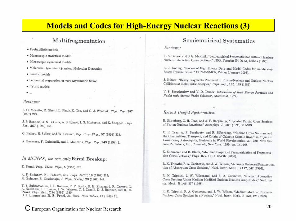
The processes are calculated by intra- and inter-nuclear cascade codes developed by several laboratories in the world Reviews by Hiroshi Takahashi, BNL (1991) & Mashnik et al., LANL (2000)

C European Organization for Nuclear Research 19
Models and Codes for High-Energy Nuclear Reactions (2)
C European Organization for Nuclear Research 20
Models and Codes for High-Energy Nuclear Reactions (3)

C European Organization for Nuclear Research 21
Models and Codes for High-Energy Nuclear Reactions (4)

C European Organization for Nuclear Research 22
Models and Codes for High-Energy Nuclear Reactions (5)

C European Organization for Nuclear Research 23
Models and Codes for High-Energy Nuclear Reactions (6)

C European Organization for Nuclear Research 24
Physics of Sub-Critical Systems (1)
• In Accelerator-Driven Systems a Sub-Critical blanket surrounding the spallation target is used to multiply the spallation neutrons.

C European Organization for Nuclear Research 25
Physics of Sub-Critical Systems (2)
ADS operates in a non self-sustained chain reaction mode
minimises criticalityand power excursions
ADS is operated in a sub-critical modestays sub-critical whetheraccelerator is on or offextra level of safety againstcriticality accidents
The accelerator provides a controlmechanism for sub-critical systems
more convenient thancontrol rods in critical reactor
safety concerns, neutroneconomy
ADS provides a decoupling of the neutron source (spallation source) from the fissile fuel (fission neutrons)
ADS accepts fuels that would not be acceptable in critical reactors
Minor ActinidesHigh Pu contentLLFF...
nn
n
n
n
Fission Fission
High Energy�Proton�(1 GeV)
Externally driven process:�k < 1 (k = 0.98)Self-sustained process:�
k = 1 �(if k < 1 the Reactor stops�if k > 1 the Reactor is supercritical)��
Beam EnergyEnergy Produced
Etot = G × Ep
EnergyCritical�Reactor Amplifier
Chain Reaction Nuclear Cascade
k= ProductionAbsorption + Losses
Effective neutron multiplication factor
n nLosses Capture
(200 MeV/fission�~ 2.5 n/fission)��
(200 MeV/fission�~ 2.5 n/fission)��Fission
Losses CaptureFission
⇒ The time derivative of the power �kept equal to zero by control
⇒ Constant Energy Gain

C European Organization for Nuclear Research 26
Physics of Sub-Critical Systems : Multiplication Factor (1)
Care must be taken in the interpretation of the effective neutron multiplication factor keff(ratio between the neutron population in two subsequent generations) when dealing withan externally driven subcritical system. In the classic theory of one group diffusion forthe uniform reactor, we can write the neutron transport equation as:
1v
dψdt
= D ∇2 + B2( )ψ(x,t) (1)
If we suppose to factorise the solution as ψ (x,t) = φ(x)ϕ(t), we are left with a classicaleigenvalue problem. The eigenvalues that give the correct boundary conditions are:
B2 − n π 2
a2 =ν Σ f − Σa
D− n π 2
a2
where a is the size of the reactor. To every value of n corresponds an eigenfunction. Thetime dependent part is then:
1vD
dϕ (t)dt
= (B2 − n π 2
a2 )ϕ (t)
and to every value of n corresponds a time component:
ϕ n(t) = eDv(B2 −nπ 2 a 2) t
If B2 < π2a−2 , the reactor is subcritical and the fluence dies away. If B2 > π2a−2 , thereactor is s upercritical and it diverges. In case the reactor is not critical, an associatedcritical reactor is defined where B0
2 is defined as
B02 =
(ν / keff ) Σ f − ΣaD
=π 2
a2

C European Organization for Nuclear Research 27
Physics of Sub-Critical Systems : Multiplication Factor (2)
This is the correction that we have to apply to the average number of neutrons producedper fission to make the reactor critical. Solving for keff we have:
keff =ν Σ f
Σa + Dπ2
a2
where keff can be interpreted as the number of fission neutrons produced for each neutronabsorbed. If the system is in the eigenstate relative to B2 and not B0
2 then the netmultiplication factor due to fission is:
Meff =1
1− keffThis simple theory can be generalised in different ways to a more realistic situation, buttwo aspects are neglected since the start, i.e. the nonfission multiplicative processes andthe possible presence of an external source. The nonfission multiplication could be takeninto account as a modification of Σ a , and still the previous development would hold.
In this development keff is an intrinsic property of the system. If the fluence distributionis not an eigenstate of the operator, the net multiplication factor will be different, but thiswill not change t he value of keff. We can s till define formally a value of k asksrc = 1 −1/Msrc but it will depend on the fluence as well as on the system. In particular,in the presence of an external source, this value will depend on the position and spectrumof the source neutrons. We w ill indicate hereon with ksrc the value of k ca lculated fromthe net multiplication factor Msrc in the presence of an external source.

C European Organization for Nuclear Research 28
Physics of Sub-Critical Systems : Source Importance (1)
By definition a constant power operation requires ν / keff neutrons per fi ssion, which meansthat an external source has to provide a number of neutrons per fission which is
µeff = ν 1keff
−1
=
νMeff − 1
if they are distributed exactly as the eigenfunction of the stationary problem. In the case of anarbitrary external source, this number becomes:
µsrc = ν 1ksrc
− 1( )=ν
Msrc −1The ratio: is known as the importance of source neutrons.
µeff
µsrc
=(1− keff ) /(keff /ν)(1 − ksrc ) /(ksrc /ν)
= ϕ * (2)
The operational safety margin on k∞ for an ADS with multiplication M, can be written as
∆k∞crit M( )= k∞ M( ) ϕ *
M −1
In general, it is found that the neutron source importance grows with k and that at given k, itincreases with
the "containment" of the neutron source;
the ratio of the neutron diffusion length to the size of fissile core;
the presence of an absorbing medium, "enclosing" the fissionable core, which, in asense, limits the "widening" of the neutron flux distribution as k is increased

C European Organization for Nuclear Research 29
Physics of Sub-Critical Systems : Source Importance (2)
1
1.1
1.2
1.3
1.4
1.5
1.6
0.875 0.9 0.925 0.95 0.975 1
F*
= (
1-k e
ff)/(
1-k)
keff
I)
II)
0
0.02
0.04
0.06
0.08
0.1
0 0.02 0.04 0.06 0.08 0.1ac
tual
crit
ical
ity m
argi
n, 1
- k
eff
1 - k
1-k
C European Organization for Nuclear Research 30
Physics of Sub-Critical Systems : Spatial Distribution (1)
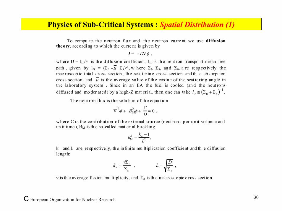
To compu te th e neut ron flux and th e neut ron curre nt we us e diffusiontheory, accordi ng to which the cu rre nt is given by
J = - D∇φ ,
where D = ltr/3 is th e diffusion coefficient , ltr is th e neut ron transpo rt mean freepath , given by ltr = (Σt - µ Σs)-1, w here Σt, Σs, an d Σa, a re resp ectively themac roscop ic tota l cross section , th e sca tter ing cross section and th e absorpt ioncross section, and µ is th e av erage va lue of th e cos ine of th e scat tering an gle inth e laboratory system . Since in an EA the fuel is cooled (an d the neut ro nsd iffused and mo der ated) by a high-Z mat eri al, then one can take ltr ≅ Σa + Σ s( )−1 .
The neutron flux is the solu tion of th e equa tion
∇ 2φ + BM2 φ +
CD
= 0 ,
where C is the contribut ion of the external sou rce (neut ron s per unit vo lum e andun it time ), BM is th e so-called mat eri al buckling
BM2 =
k∞ − 1L2 ,
k� and L are, re sp ective ly, th e infini te mu ltipl icat ion coefficient and th e diffus ionleng th:
k∞ =νΣ f
Σa
, L =DΣ a
,
ν is th e av erage fission mu ltipl icity , and Σa is th e mac roscopic c ross section.

C European Organization for Nuclear Research 31
Physics of Sub-Critical Systems : Spatial Distribution (2)
As it is well known , if we consider a finite, system, with vanishing flux at the(extrapolated) boundaries, and a source also vanishing at and outside the boundaries, wecan write the solution in terms of the eigenvectors ψ n of the characteristic "waveequation"
∇2ψ + B2ψ = 0 ,
which form a complete orthonormal basis, each eigenvector ψ n corresponding to aneigenvalue Bn . We normalize the eigenfunctions in such a way that ψ n
2∫ dV = 1; andintroduce the volume integrals of the eigenfunctions :
Ψn = ψ n (x)dVV∫ .
We then write the (known) outer source as
C(x) = cnψ n (x)n=1
∞∑ ,
with the expansion coefficients given by
cn = C(x)ψ n dVV∫ ,
so that the space integrated source neutron rate can be written as
Q = C(x) dV =V∫ cn
n =1
∞
∑ Ψn .
The (unknown) neutron flux can be expanded in the same basis, too,
φ(x) = φnψ n (x)1
∞
∑

C European Organization for Nuclear Research 32
Physics of Sub-Critical Systems : Spatial Distribution (3)
A straightforward solution is found for a homogeneous medium. Indeed, in this case, bysubstituting the expansions for the source and the flux we obtain an independent equation foreach n, giving the coefficient of the flux as a function of that of the source :
φn =1
Σa
cn
1− (k∞ − Bn2 L2 )
=cn
Σa (1+ Bn2 L2 )
11 − kn
,
where
kn =k∞
1 + Bn2L2 .
As anticipated, we see that if al l kn's are smaller then unity, then the flux is given by a linearsuperposition of eigenmodes; as soon as k1 = 1 the system becomes critical; the source is no moreneeded to sustain the system, and the only surviving mode is the fundamental one.
If k∞ −1
L2 > 0, the solutions are of sinus form: Ψlmn =8
abcsinπ
lxa
⋅sinπmyb
⋅sinπnzc
;
If k∞ − 1
L2 = −γ 2 , he solutions are of exponential form:
Ψ(x) = A1e− γx + B1e
γx
Ψ(y) = A2e−γy + B2e
γy
Ψ(z) = A3e−γz + B3e
γz
;

C European Organization for Nuclear Research 33
Physics of Sub-Critical Systems : Spatial Distribution (4)
0 0.2 0.4 0.6 0.8 1–0.2–0.4–0.6–0.8–1
Distance from Centre (arbitrary units)
0.0
0.1
0.2
0.3
0.4
0.5
0.6
CriticalReactorneutrons
Spallationneutrons
Fissionneutronsk = 0.9
Ne
utr
on
Flu
x
(
arb
itra
ry u
niit
s)SPATIAL DISTRIBUTION OF THE NEUTRON FLUX

C European Organization for Nuclear Research 34
Physics of Sub-Critical Systems : Source Amplification (1)
In an accelerator driven, sub-critical fission device the "primary" (or "source") neutrons produced via spallation initiate a cascade process.
The source is then "amplified" by a factor M the beam power is "amplified" by a factor G = G0M
If we assume that all generations in the cascade are equivalent, we can define an average criticality factor k (ratio between the neutron population in two subsequent generations), so that:
M = 1+ k + k2 + k3 + ... =1
1− kHence:
Energy Gain: G ≡Energy Produced by ADSEnergy Provided by Beam
=G0
1− k( )
The G0 constant contains the spallation information: G0 ~ 3 for uranium, G0 ~ 2.7 for lead.

C European Organization for Nuclear Research 35
Physics of Sub-Critical Systems : Source Amplification (2)
0
5
10
15
20
25
30
35
40
0 0.5 1 1.5 2 2.5 3 3.5
En
erg
y g
ain
Proton Kinetic Energy (GeV)
Avg. Measured Gain Monte Carlo Gain
Energy gain vs. kinetic energy�(Average from all counters & MonteCarlo)
G = ~ 30G0
(1 - k)
G0 ~ 3�k ~ 0.9
S. Andriamonje et al., Phys. Lett. B348 (1995) 697-709

C European Organization for Nuclear Research 36
Review of Sub-Critical Core Experiments
Highly specified experiments have been carried out to verify thefundamental physics principle of Accelerator-Driven Sub-Critical Systems:
The First Energy Amplifier Test (FEAT): S. Andriamonje et al. Physics Letters B 348 (1995) 697–709 and J. Calero et al. Nuclear Instruments and Methods A 376 (1996) 89–103;
The MUSE Experiment (MUltiplication de Source Externe): M. Salvatores et al., 2nd ADTT Conf., Kalmar, Sweden, June 1996;
The YELINA Experiment (ISTC-B-70): S. Chigrinov et al., Institute of Radiation Physics & Chemistry Problems, National Academy of Sciences, Minsk, Belarus.

C European Organization for Nuclear Research 37
The FEAT Experiment (1)
The core of the concept (giving in fact its name to the “Energy Amplifier”) is the production of substantial amounts of energy, over and above the kinetic energy brought in by the accelerator beam.
From that stems the concept of an "energy gain" G. In conditions of practical interest, the gain is predicted to be G = 30 to 60, which, taking into account the relevant efficiencies, was easily shown to be much more than is needed to power the accelerator.
The main purpose assigned to the test is therefore to ascertain that there is such a gain and that its magnitude is in agreement with the value predicted by the simulation.
The beam intensity that we used (of the order of 108 protons/second) was much smaller (by five orders of magnitude) than the one normally delivered by the CERN Proton Synchrotron (PS);
The power produced during the test was 1 Watt, i.e. nine orders of magnitude less than that of a fully fledged 1000 MW EA unit necessitating a dedicated high intensity accelerator (typically, a few mA of proton beam at 1 GeV);
The total energy release in the volume of the assembly is calculated by taking the heat release measured at the different points by the thermometers and the variation with distance of the energy release to perform the integration over the volume. The thermometers register the complete energy release not only from fission fragments but also from gammasfollowing neutron capture and from radioactive decays.

C European Organization for Nuclear Research 38
The FEAT Experiment (2)

C European Organization for Nuclear Research 39
The FEAT Experiment (3)
Stainless steel
flang
313 BAR POSITIONS
270 BARS WITH URANIUM &
10 EMPTY BARS
Stainless steel
vessel
Water
Ura
nium
bar
s
155
125 35 15
.8
50.8
600
BEAM

C European Organization for Nuclear Research 40
The FEAT Experiment (4)
The neutronic behavior of the assembly has been calibrated with the help of a 58 GBqneutron source (Am-Be) inserted in the centre of the device. The neutron flux measured with a boron loaded counter is shown below, and confirms the expected exponential behavior as a function of the distance from the source.
We find a multiplication factor for a point-like centeredsource of k = 0.915 ± 0.010. This is in good agreement with EA-MC calculations which give k = 0.920 ± 0.005.
0.0�
0.2�
0.4�
0.6�
0.8�
1.0�
1.2�
1.4�
0� 100� 200� 300� 400� 500� 600�
Neu
tron
flux
dist
ribut
ion
(arb
itrar
y un
its)�
Distance from the source (mm)�
FEAT meas. ( Ksrc ≈ 0.915 ± 0.010 )�EA-MC calc. ( Ksrc ≈ 0.920 ± 0.005 )�MCNP4B calc. ( Ksrc ≈ 0.908 ± 0.004 )�MCNP4B calc. ( Keff ≈ 0.868 ± 0.002 )�
EA-MC "source mode"�
MCNP-4B "reactor mode"�
MCNP-4B "source mode"�

C European Organization for Nuclear Research 41
The MUSE Experiment

C European Organization for Nuclear Research 42
The YELINA Experiment (1)

C European Organization for Nuclear Research 43
The YELINA Experiment (2)

C European Organization for Nuclear Research 44
The YELINA Experiment (3)

C European Organization for Nuclear Research 45
The YELINA Experiment (4)Experiment & calculations:
keff vs. fuel load
0,87�
0,89�
0,91�
0,93�
0,95�
0,97�
0,99�
210� 220� 230� 240� 250� 260� 270� 280� 290� 300�
Number of fuel rods
CERN JAR (newgeo)�CERN JENDL (newgeo)�CERN JAR (oldgeo)�CIEMAT JENDL32�CIEMAT ENDF6�Minsk ENDF�Minsk prel. exp.�Exp. data, channel 1�Exp. data, channel 2�Exp. data, channel 3�
k eff