ia543 intercom amplifier - alpha communicationsâ„¢
TRANSCRIPT

1
IA543 Intercom Amplifier
Installation & Configuration Manual The Alpha Communications® IA543 Intercom Amplifier is designed to allow two-way communications between an open voice lobby panel and multiple apartments. Additional equipment will allow communications with multiple entrance panels. Entrance panels will signal up to an apartment by pressing the corresponding call button, and the resident can answer using TALK and LISTEN buttons. A DOOR button provided on the apartment station can be configured to operate an electric door strike or magnetic lock to allow visitor entry. The IA543 is compatible with additional equipment to provide specialized applications and features such as hearing impaired strobe lights, multiple sequenced door operations, integration into access control systems, and Postal locks. INSTALLATION PROCEDURE Read this manual to insure proper wiring, component placement, and installation methods. WIRING REQUIREMENTS Depending on the facility layout and number of apartments, inside stations may be connected by risers comprised of common wires with selective wires from each inside location, or connected in a home run method from each inside location. Apartment stations can be of the 3, 4, or 5 wire varieties and can be used in combination if necessary.
Alpha Communications® 42 Central Drive Farmingdale, NY 11735-1202 Toll Free: 1-800-666-4800 Phone: 631-777-5500 Fax: 631-777-5599
Website: www.AlphaCommunications.com Email: [email protected]
Copyright© 2010-2017AWD142 Alpha Communications® All Rights Reserved. AWD143 Rev. 3 (01/2018)
Please note: Terminal identifications in this manual may not be shown in the actual order that they appear on the equipment.

2
COMPONENT INFORMATION APARTMENT STATIONS
Locate stations in a convenient location. Recommended height is 60” A.F.F. for most applications. If inside stations are flush mount style, install proper back box or housing. Run appropriate wires with sufficient extra length for ease of service and installation. Avoid mounting near kitchen areas where cooking grime may build up. Avoid mounting near other electrical equipment that may cause electrical interference and static noise. AMPLIFIER Mount amplifier in a clean, dry area away from electrical equipment that could cause noise and interference on the system. Entry panel back boxes may be used to house the amplifier in some installations providing they will offer suitable protection from heat, dirt and moisture. Do not mount the power transformer within 3 feet of the amplifier. Check all wiring for shorts and grounds before applying system power. TRANSFORMER The transformer must be mounted in a clean, dry area, and in accordance with all applicable codes, at a distance of 3 to 80 feet (1 to 25 meters) from the amplifier using #18AWG wire. In cases where this distance must be exceeded, use a heavier gauge wire to reduce voltage drop. ENTRY PANEL(S) Mount all entry panels in a suitable location protected from harsh weather and water. Although many panels are weather resistant, the more protection you can provide, the longer the life expectancy will be. When mounting flush style panels, always use protective back boxes or appropriate housings. In the case of multiple entry systems, additional equipment, such as the IA502 or PK502B multi-entrance adapter, may be required. DOOR RELEASE The IA543 easily allows several door release configurations. Always use a minimum of #18AWG 2 conductor wire up to a maximum distance of 50 ft. (15 meters). In cases where this distance must be exceeded, use a heavier gauge wire to reduce voltage drop. Always run these wires separately from the entry speaker cable to prevent interference and noise. Special applications may require additional hardware such as the PK407A isolation relay, or RY502A Dual Door Timed Switcher Relay. Some applications may require a separate power supply for the door release device. Please refer to the next page for specific wiring and jumper positions.
When running any audio wiring please make sure not to run too close to any source of electrical interference, such as fluorescent lights, ballasts, dimmers, other electrical wiring, electromagnetic interference (EMI), etc.

3
DOOR RELEASE DIAGRAMS
Set jumpers as shown in the chart below. This supplies 16VAC to the door strike through the K & D terminals when the inside station DOOR Button is pressed. The length of activation time is determined by the dipswitch settings (approx. 2, 10, or 25 seconds).
Set jumpers as shown in the chart below. This example shows the wiring for a Multi-Tap Transformer (8/16/24 VAC) to supply 24VAC to a door strike when the inside station DOOR Button is pressed, while also supplying 16VAC for system power. Pay special attention to the transformer wiring and terminal markings. The length of activation time is determined by the dipswitch settings (approx. 2, 10, or 25 seconds).
Set jumpers as shown in the chart below. This configuration supplies continuous 24VDC to a magnetic lock through the L+ & L- terminals which is shut off when the inside station DOOR Button is pressed allowing the door to be opened. Insure that proper polarity is observed.
16VAC DOOR
STRIKE
24VAC DOOR
STRIKE
24VAC DOOR
STRIKE
24VDC MAG LOCK

4
DOOR RELEASE DIAGRAMS - continued
Set jumpers as shown in the chart below. This configuration is used when a magnetic door lock has its own dedicated power supply. The PK407A only provides a dry contact which in this Normally Closed mode, allows voltage to flow to a magnetic lock through the B & A terminals. When the inside station DOOR Button is pressed, the relay opens the circuit, disconnecting the power and releases the door. Insure that proper polarity between the magnetic lock and its power supply is observed. The length of door release time is determined by the dipswitch settings (approx. 2, 10, or 25 seconds).
USING THE
PK407A ISOLATION
RELAY for a
MAG LOCK
To use the PK407A as an isolation relay for a door strike with a separate power supply, the wiring and jumper settings are the same as above, except the wire going to the B terminal (Normally Closed) would go to the A terminal (Normally Open) instead. This way power from the IA543 would close the connection to apply power to the door strike and release the door.
USING THE PK407A
ISOLATION RELAY
for a DOOR
STRIKE
5
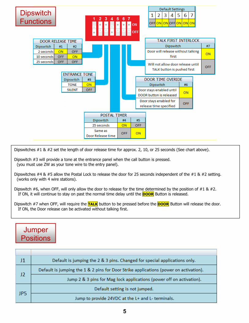
Dipswitch Functions
Jumper Positions
Dipswitches #1 & #2 set the length of door release time for approx. 2, 10, or 25 seconds (See chart above). Dipswitch #3 will provide a tone at the entrance panel when the call button is pressed. (you must use ZW as your tone wire to the entry panel). Dipswitches #4 & #5 allow the Postal Lock to release the door for 25 seconds independent of the #1 & #2 setting. (works only with 4 wire stations). Dipswitch #6, when OFF, will only allow the door to release for the time determined by the position of #1 & #2. If ON, it will continue to stay on past the normal time delay until the DOOR Button is released. Dipswitch #7 when OFF, will require the TALK button to be pressed before the DOOR Button will release the door. If ON, the Door release can be activated without talking first.

6
MAIN SYSTEM DIAGRAM
The IA543 amplifier has two serviceable adjustments for Voice Volume and Tone Volume located through two access holes on the front cover. Use a small screwdriver and do not use excessive force. Carefully turn clockwise to increase the volume. High volume setting may result in feedback oscillation.
TYPICAL 4 WIRE STATION – BACK VIEW
7
8
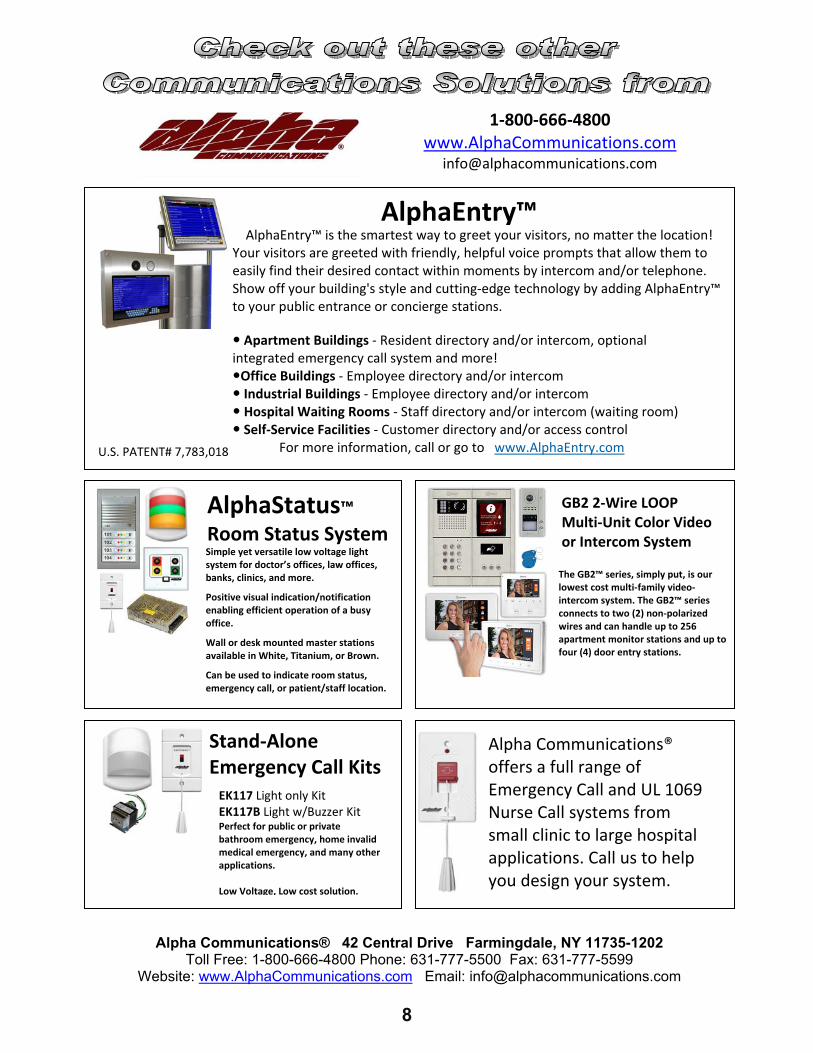
AlphaEntry™ is the smartest way to greet your visitors, no matter the location! Your visitors are greeted with friendly, helpful voice prompts that allow them to easily find their desired contact within moments by intercom and/or telephone. Show off your building's style and cutting‐edge technology by adding AlphaEntry™ to your public entrance or concierge stations.
Apartment Buildings ‐ Resident directory and/or intercom, optional integrated emergency call system and more! Office Buildings ‐ Employee directory and/or intercom Industrial Buildings ‐ Employee directory and/or intercom Hospital Waiting Rooms ‐ Staff directory and/or intercom (waiting room) Self‐Service Facilities ‐ Customer directory and/or access control . For more information, call or go to www.AlphaEntry.com
1‐800‐666‐4800 www.AlphaCommunications.com
AlphaEntry™
Simple yet versatile low voltage light system for doctor’s offices, law offices, banks, clinics, and more.
Positive visual indication/notification enabling efficient operation of a busy office.
Wall or desk mounted master stations available in White, Titanium, or Brown.
Can be used to indicate room status, emergency call, or patient/staff location.
AlphaStatus™ Room Status System
GB2 2‐Wire LOOP Multi‐Unit Color Video or Intercom System
The GB2™ series, simply put, is our lowest cost multi‐family video‐intercom system. The GB2™ series connects to two (2) non‐polarized wires and can handle up to 256 apartment monitor stations and up to four (4) door entry stations.
Stand‐Alone Emergency Call Kits EK117 Light only Kit EK117B Light w/Buzzer Kit Perfect for public or private bathroom emergency, home invalid medical emergency, and many other applications. Low Voltage, Low cost solution.
Alpha Communications® offers a full range of Emergency Call and UL 1069 Nurse Call systems from small clinic to large hospital applications. Call us to help you design your system.
Alpha Communications® 42 Central Drive Farmingdale, NY 11735-1202 Toll Free: 1-800-666-4800 Phone: 631-777-5500 Fax: 631-777-5599
Website: www.AlphaCommunications.com Email: [email protected]
U.S. PATENT# 7,783,018