i part i - reports a and b • part ii - reports c, d, e...
TRANSCRIPT

II
GEOTECHNICAL ADVISORY COMMITTEE
I DENVER WATER DEPARTMENT
I
IGEOLOGIC SEISMOTECTONIC INVESTIGATIONS
• CENTRAL FRONT RANGE, COLORADO
I
I| THIRD INTERIM REPORT
I
II PART I - REPORTS A AND B
• PART II - REPORTS C, D, E, F, AND G
PART III - REPORT H
• PART IV - REPORTS I, J, AND K
| PART V - REPORT L
PART VI - REPORTS M, N, O, P, Q, AND R
II

IIIIIIIIIIIIIIIiIII
GEOLOGIC AND SEISMOTECTONIC INVESTIGATIONS
CENTRAL FRONT RANGE, COLORADO
THIRD INTERIM REPORT
by
GEOTECHNICAL ADVISORY COMMITTEEDENVER WATER DEPARTMENTDENVER, COLORADO 80254
NOVEMBER, 1985
COMMITTEE MEMBERSHIP:
Denver Water Department, Denver, COV. Q. Hornback, GeologistJ. P. Parsons, EngineerSusan G. Steele, Geologist
Harza Engineering Company, Chicago, ILE. E. Komie, GeologistR. A. Paige, GeologistR. P. Wengler, Engineer
MicroGeophysics Corporation, Wheat Ridge, CoDavid Butler, Geophysicist
John J. Nicholl, Jr., Geophysicist
Independent ConsultantsE. E. Wahlstrom, Geologist, Chairman, Redmond, WA
L. A. Warner, Geologist, Boulder, CO
Out side Consult ant sC. R. Allen, Geologist and Geophysicist, Pasadena, CA
R. J. Shlemon, Geologist, Newport Beach, CADale M. Cochran, Geologist, Denver, CO

IIIIIIIIIIIIIIIIIII
THIRD INTERIM REPORT
TABLE OF CONTENTS
TABLE OF CONTENTS
GENERAL STATEMENT
REPORT A.
REPORT B.
REPORT C.
REPORT D.
REPORT E.
REPORT F.
REPORT G.
REPORT H.
REPORT I.
REPORT J.
REPORT K.
REPORT L.
Ken Caryl trench site geology, by HarzaEngineering Company.
Air Force Academy trench site geology, by HarzaEngineering Company.
Geologic investigations at the Reynolds Parktrench site, by Earth Science Associates.
Soil-geomorphic assessment, Ken Caryl, ReynoldsPark, and Air Force Academy trench sites, CentralFront Range, Colorado, by R. J. Shlemon.
Quaternary stratigraphy, terrace sequences andradiocarbon dates, Central Front Range, Colorado,by R. J. Shlemon.
Geologic studies along the Shawnee fault near theproposed Estabrook dam and reservoir site, ParkCounty, Colorado, by V. Q. Hornback.
Kermits Gulch study area: Floyd Hill fault, byHarza Engineering Company.
Air-photo lineament analysis, East-Central FrontRange, Colorado, by Susan G. Steele.
Geotectonics of Central Colorado: implicationsfor stress distribution and seismic potential, byL. A. Warner.
Letter by Clarence R. Allen, 6 November, 1985.
Field investigations of Kennedy Gulch and WillowCreek fault zones near the proposed Two Forks damand reservoir site, by V. Q. Hornback.
Front Range Seismicity study, progress report ,February 1983 - May 1985, by John J. Nicholl, Jr.and David Butler.

IIIIIIIIIIIIIIIIIII
REPORT M.
REPORT N.
REPORT O.
REPORT P.
REPORT Q.
REPORT R.
Seismic design considerations; Two Forks,Estabrook, Ferndale, New Cheesman, Williams Fork,and Gross dam and reservoir sites, by DavidButler and John J. Nicholl, Jr.
Gravity feasibility study, by David Butler andJohn J. Nicholl, Jr.
Seismicity of the Conifer, Colorado Earthquake,by David Butler and John J. Nicholl, Jr.
The Divide Earthquake of January 6, 1979, byDavid Butler and John J. Nicholl, Jr.
Attenuation of ground motions from quarry shots,by John J. Nicholl, Jr. and David Butler.
Velocity model analysis, by John J. Nicholl, Jr.

FGENERAL
STATEMENT

IIIIIIIIIIIIIIIIIII
GENERAL STATEMENT
The Geotechnical Advisory Committee of the Denver WaterDepartment plans, supervises, and reviews all geotechnical in-vestigations that contribute to the development of additionalwater storage and diversion facilities on the eastern slope ofthe Colorado Front Range by the Department and cooperating agen-cies. The ultimate goal of the committee is the careful identi-fication and thorough evaluation of all geotechnical factorsthat must be taken into account in the design and economicalconstruction of safe facilities. Particular attention is givento considerations of seismic safety, regional geology of bedrockand surficial deposits, and the geology of proposed dam, reser-voir, and tunnel locations.
The committee meets periodically, usually once a month, atthe Denver Water Department and/or at the locations of ongoingfield investigations. As appears desirable, the committeeutilizes outside consultants to assist in investigations requir-ing specialized knowledge and experience. Currently, the com-mittee is utilizing the services of Clarence R. Allen, a notedexpert in geology and seismicity, especially reservoir-inducedseismicity, Dale M. Cochran, a skilled field geologist, and RoyJ. Shlemon, a recognized authority on Quaternary Geology andSoil Stratigraphy.
ESA Geotechnical Consultants (Earth Science Associates) ofFort Collins, Colorado, were retained during the 1985 fieldseason to excavate and log a trench in Quaternary deposits atthe headquarters of Reynolds Park in Jefferson County,Colorado.
This report, the third in a series of Interim Reports,describes and summarizes the investigations and deliberations ofthe committee completed during the field season of 1985. It isplanned to prepare a summary report which will bring together incondensed format the data and conclusions included in all threeinterim reports, including this report.

REPORT A

REPORT A
KEN CARYL TRENCH SITE
GEOLOGY
THIRD INTERIM REPORT
IIIIIIIIIIIIII• by
Harza Engineering Company
| November, 1985
I
I
I

IIIIIIIIIIIIIIIIIII
KEN CARYL TRENCH SITEGEOLOGY
TABLE OF CONTENTS
Page
TABLE OF CONTENTS i
TABLE i i
ILLUSTRATIONS ii
ABSTRACT iii
ACKNOWLEDGEMENTS iii
INTRODUCTION 1
Purpose and Scope 1Location 1Geologic Setting 1
FIELD EXPLORATION 2
General 2Trench Excavation 3Trench Logging 3Geologic Mapping 4
GEOLOGY OF TRENCH 5
Bedrock Geology 5
Rock Types 5Bedrock Structure 5
Quaternary Geology 7
Stratigraphy 7General 7Unit 1 7Unit 2 8Unit 3 8
Structure in Surficial Deposits 9Interpretation of Quaternary Geology 9Age of Sediments 10
CONCLUSIONS ON AGE OF FAULTING 11
REFERENCES CITED 12

II
TABLE
I Page
• Table 1 Ages of Sediments and Soils 11
ILLUSTRATIONS
I
Figure 1 Map Showing Location of Ken Caryl FollowingTrench Site Text
Figure 2 Geologic Map of Ken Caryl Site FollowingText
• Plate 1 Geologic Log of Trench KC-1 In Pocket
Plate 2 Geologic Log of Trench KC-1 In Pocket
I
I
I
I
I
I
I
I
I
I

IIIIIIIIIIIIIIIIIII
ABSTRACT
Detailed investigations were conducted at the Ken Carylsite, Jefferson County (Indian Hills quadrangle), to obtain andevaluate evidence of the presence or absence of Quaternaryfaulting and to assess the minimum age for the most recent faultmovements. Previous geologic mapping at the site had indicatedthe occurrence of datable Quaternary deposits overlying the KenCaryl fault, a major splay of the Floyd Hill fault which hasbeen indicated by others as potentially active (Kirkham andRogers (1981).
A 630-foot long trench was excavated to bedrock across anarea that included the mapped trace of the Ken Caryl fault. Thetrench was geologically logged in detail and the surficial geo-logy of the site and adjacent areas mapped.
Three major sedimentary units and their related pedogenicprofiles were exposed in the trench overlying bedrock. Thesedeposits and the bedrock-overburden contact are not offset byany tectonic fault nor show evidence of any other tectonic dis-turbance. The Quaternary deposits are thought to range in agefrom about 100,000 to perhaps as much as 250,000 years old.They underlie a geomorphic surface at the site which shows noevidence of tectonically-influenced erosional and/or deposi-tional features. Because these deposits and the geomorphicsurface show no evidence of tectonic disturbance, it is con-cluded that the latest movement on the Ken Caryl fault tookplace in this area more than 100,000 and possibly well before250,000 years ago.
ACKNOWLEDGEMENTS
Permission to enter the property to conduct the requiredwork was kindly granted by Valley Joint Venture of Littleton,Colorado. The assistance of Mr. Stan Brown, DevelopmentManager, concerning access and site reclamation, is acknow-ledged.
We were pleased that several interested geologists who werenot part of the investigation team took time to visit the openexploratory trench and provide technical discussion in thefield. These included Glenn Scott, Bruce Bryant, Rich Madole,and R.A. Wobus of the U.S. Geological Survey; Bob Kirkham of theColorado Geological Survey; and several geologists from the U.S.Bureau of Reclamation, including Dave Allen, Ben Bennett, andDean Ostenaa.
-iii-

II_ The administrative and logistical support provided by• Denver Water Department staff Jack Parsons, Quent Hornback, and* their geologists and surveyors during this study is greatly
appreciated.
I
I
I
I
I
I
I
I
I
I
I
I
I
I
I
-iv-

IIIIIIIIIIIIIIIIIII
INTRODUCTION
Purpose and Scope
This report presents the results of detailed geologic in-vestigations conducted at the Ken Caryl site during 1985. Theinvestigations were an integral part of the continuing seismo-tectonic evaluations for the proposed Two Forks and alternativedamsites in the Colorado Front Range.
The primary objectives were to collect and document evi-dence in bedrock, surficial deposits, and landforms that couldbe related to the presence or absence of tectonic faulting with-in the area and to assess the age of the latest fault movements.The investigations involved excavation and logging of an explor-atory trench and mapping of Quaternary deposits and bedrockexposures across the previously mapped trace of the Ken Carylfault. This fault is a major splay of the Floyd Hill fault andboth are indicated as potentially active by Kirkham and Rogers(1981). The site had been identified earlier as being suitablefor investigation by trenching because of the presence ofQuaternary deposits overlying the mapped trace of the Ken Carylfault (Harza Engineering Company, 1985). Interpretation of theages of undisplaced Quaternary deposits overlying the faultprovides a minimum age for the most recent fault movement and anindication of relative fault capability. Age interpretationsare discussed by Dr. R. J. Shlemon elsewhere in this InterimReport (Report D) and are summarized in this report underQuaternary Geology.
Location
The Ken Caryl site is located in Jefferson County, 14 milessouthwest of Denver, on land formerly part of the old Ken CarylRanch, Figure 1. The site is found in the NE 1/4, Sec 36, T5S,R70W on the Indian Hills 7-1/2' quadrangle sheet.
Geologic Sett ing
The site is situated on a dissected geomorphic surfacesloping eastwards away from the Front Range foothills. It is ina broad valley between the Front Range foothills to the west andprominent hogbacks to the east and between Turkey Creek to thenorth and Deer Creek to the south. This piedmont area isdrained by small intermittent streams that join to form MasseyDraw, a tributary of Deer Creek.
The Indian Hills geologic quadrangle map (Bryant andothers, 1973) shows that the mountainous area to the west is
-1-

IIIIII1IIIIIIIIIIII
underlain by a Precambrian metamorphic rock complex of gneisses,migmatites, amphibolites, and quartzites. The broad Ken CarylRanch valley is largely underlain by sandstones belonging to theFountain Formation of Pennsylvanian-Permian age. Sedimentaryrocks ranging in age from Permian to Cretaceous occur to theeast with more resistant units forming the prominent hogback(largely South Platte and Lytle Formations) and a lower ridgejust to the west (Lyons Sandstone).
In the study area, the Fountain Formation bedrock is large-ly concealed beneath various Quaternary alluvial and slopewashdeposits. According to Bryant and others (1973), these includein order of decreasing age, Slocum Alluvium, undifferentiatedolder Pleistocene alluvium and colluvium, Pre-Piney Creek Allu-vium, and Post-Piney Creek Alluvium. The source areas of thesedeposits are steep, narrow drainages in the mountain front tothe west. Thus the provenance of most material is largely thePrecambrian metamorphic rock complex but also includes somereworked sand and rock fragments from the Fountain Formation.
The USGS map indicates that, in the study area, thePhanerozoic sedimentary formations dip mostly ENE at about 15°to 30° (Bryant and others, 1973). A segment of the Ken Carylfault is shown passing through the study area concealed by sur-ficial deposits. The closest exposures of the fault exist about1/2 mile to the northwest and south of the site. Bryant andothers (1973, p. 6) infer that the direction of post-Fountainmovement was predominantly dip-slip with the east side of thefault upthrown about 500 feet.
FIELD EXPLORATION
General
A 630-foot long exploratory trench, KC-1, was excavated inthe location shown on Figure 2. The trench location and align-ment were selected to explore the preserved Quaternary sectionalong the top of a low east-west trending ridge that extendscompletely across any logical projections of the Ken Caryl faulttrace. The ridge is the remnant of a dissected geomorphic sur-face capped by deposits shown by Bryant and others (1973) asSlocum Alluvium. The results of site reconnaissance and aerialphoto examination suggested that the ridge was probably the bestof several possible sites that would provide good prospects forpreservation of older Quaternary deposits over the full width ofthe Ken Caryl fault trace. Moreover the site was readily acces-sible by excavating equipment.
-2-

IIIIIIIIIIIIIIIIIII
Trench Excavation
Trench KC-1 was excavated along the top of the ridge usinga Koehring tracked backhoe equipped with a 36-inch bucket. Thetrench was oriented approximately east-west, except for a smallsection between Stations 2+80 and 3+95 due to a slight misalign-ment of the backhoe. The total length of the trench was 630feet and the elevation of the top of the excavation ranged from6166 feet at the eastern end to 6204 feet at the western end.The excavation reached bedrock along the entire length. Thedepth of the trench ranged from about six to 17 feet and thewidth of the vertical cut at the bottom averaged about four feetwhile the upper part, which had to be flared out for safetyreasons, averaged about 15 feet in width.
Excavation started on June 24, 1985, and the trench wasbackfilled by July 31, 1985, after all technical documentationhad been completed. Spoil was placed on the south side of thetrench with the toe of the spoil pile kept at least six feetfrom the edge of the excavation to minimize surcharge loadingand to provide adequate access. Trench walls were cut as nearto vertical as practical to facilitate shore setting andlogging. Wood shoring was utilized throughout the excavation toensure safety and maintain the side slopes until technical log-ging was completed. Aluminum ladders were provided at about25 feet intervals.
Loose material on the sides and bottom of the trench anddisturbed or contaminated material resulting from smear of theexcavator bucket were removed by hand. In general, except forthe uppermost soil layers, the materials along the trench wallswere strong and cohesive, having little tendency to cave evenafter repeated wetting and drying following rainshcwers. Exceptfor some small puddles that accumulated after rain, the trenchwas dry with no groundwater inflow.
Site reclamation specifications required backfilling inlimited lifts, watering, and compaction with a vibratingsheep's-foot roller to obtain 90% of maximum modified Proctordensity. Final procedures involved fine-grading and seeding.
Trench Logging
The south side of the trench was selected for logging asthis would be in indirect sunlight for the longest time. Hori-zontal control (stationing) was established by taping along thetop of the trench (from east to west) and dropping down plumb-lines at five-foot intervals. A single reference point wasutilized for all vertical control on the site. This TBM (a naildriven into the bottom of a utility pole) was assigned anarbitrary
-3-

IIIIIIIIIIIIIIIIIII
elevation of 100 feet. Subsequent surveying established itsactual elevation above sea level as 6189.6 feet. Vertical con-trol in the trench was provided by strings attached to shoringat two-foot vertical intervals.
Logging involved recording information observed on thetrench wall onto graph paper at a scale of 1 inch = 2-1/2 feet.The geologic logging included descriptions of grain size, sort-ing, rounding, lithology, weathering, color (using the standardMunsell Soil Color Chart), contacts, and structures. The oppo-site trench wall was locally cleaned and examined in order tofollow contacts, structures, or lithologic units in the thirddimension. This information is presented on Plates 1 and 2 andform the basis for interpreting the geologic history and rela-tive ages of the units logged.
The entire site and excavation were also photographed using35 mm color print and slide film. However, due to the narrow-ness of the trench and use of wide-angle lenses, photographsexhibit considerable distortion and therefore are not as valu-able for technical documentation as the graphic logs. A com-plete set of project photographs is on file at the EWD offices.
Geologic Mapping
During 1984, reconnaissance geologic mapping was conductedalong the entire length of the Ken Caryl fault (Harza Engineer-ing Company, 1985). In the 1985 investigations, additionaldetailed geologic mapping was performed in the vicinity of thetrench at a scale of one inch = 400 feet (Figure 2). Stereo-scopic pairs of aerial photographs also were the examined,revealing the absence of any linears crossing the area thatcould be attributed to tectonic structure.
Considerable construction activity associated with housingdevelopments has been taking place over the last two years inthe Ken Caryl Ranch area. Foundation excavations for roads andhouses as well as pipeline trenches were routinely examinedduring this study as a further source of geologic information.The nearest exposures of the Ken Caryl fault to the trench loca-tion were found to be 3,200 feet to the south and 3,500 feet tothe NNW. The former consists of a 50 foot-wide zone of highlysheared Fountain Formation (now obscured by new buildings) andthe latter of faulted Precambrian hornblende and calc-silicategneisses.
-4-

IIIIIIIIIIIIIIIIIII
GEOLOGY OF TRENCH
Bedrock Geology
Rock Types
Bedrock was exposed to a depth of six inches to three feetat the bottom of the trench along its entire length. Rock typesare various interbedded sandstone facies characteristic of theFountain Formation (Pennsylvanian-Permian). The two dominantlithologies are a moderately hard, coarse-grained sandstone,mostly yellow-brown to off-white (possibly bleached)/ and amoderately hard to soft shaley sandstone which is typically darkred-brown to purple and commonly micaceous. These are indicatedas Units 4a and 4b on Plates 1 and 2 respectively and alternatein massive and near homogeneous beds ranging in thickness fromone to 10 feet. Occasional thin red-brown to purple shale bedsand gray-green sandstones also occur. Most contacts are sharpbut transitional facies are also present.
Weathering was pronounced within the depth to which bedrockwas exposed, and typically involves loss of cementation andmobilization of iron and manganese oxides, and possible bleach-ing of the characteristic red color in the sandstones.
The differing physical properties among the interlayeredsandstone beds resulted in the varying depth to which it waspossible to excavate the trench.
Bedrock Structure
Bedrock strata strike on average N 20°W with dips rangingfrom 10° to 30° to the east. No abrupt changes in dip or strikeover short distances were apparent in the trench other than adip-reversal at Station 1+40 to 1+60.
Rock jointing is generally indistinct, probably largelybecause of the coarse-grained nature of the sandstone. The mostprominent fractures are subvertical joints oriented about north-south to N 20°W. Closely-spaced fractures of this set are evi-dent at Station 1+85 to 1+90, Station 2+90, and Station 4+10,some with conspicuous displacement and clay-infilling. Shearzones occur at Station 1+87 and Stations 4+45 to 4+50, compris-ing areas of closely spaced jointing, slight brecciation, andstrong staining by manganese and iron oxides. Considerabledisplacement may have taken place within these zones as indicat-ed by the rotated fabric of some blocks between shear joints.
No area of obvious faulting, such as a zone of pervasivebrecciation or gouge, was observed however, despite the fact
—5 —

IIIIIIIIIIIIIIIIIII
that the trench spans the mapped trace of the Ken Caryl fault.Various possibilities are offered in explanation of this pro-blem:
1. The fault by-passes the trench location;
2. The fault is manifested by the previously mentionedshear zones;
3. The fault is present underlying the trench alignmentand for some reason was not detected or recognized;or
4. The fault is not a major feature at this location.
In answer to the first proposition, the trench is thoughtto have been correctly located because geological reconnaissancehad confirmed the mapped location of the fault in exposures nottoo far away, 3200 feet south of the trench site (see Figure 2)and about 3500 feet to the north. Several scattered outcrops ofapparently unfaulted Fountain Formation, shown on Figure 2,constrain passage of the fault trace through a somewhat limitedcorridor which was spanned by the trench. However, because ofdeep surface weathering, subtle fault features may not have beenrecognizable.
The areas of sheared rock observed in the trench can beevidence of faulting, but are not comparable to breccia zones offaulted Fountain Formation seen elsewhere in the region. It isalso possible that the fault in this area is manifest in subtlefeatures that were not observed in the trench because of deepweathering or occurrence in a particular lithology that does notobviously display tectonic structures.
It is possible that the fault does not in fact occur atthis point, that it is a discontinuous structure at the surface,rupturing only a limited thickness of Phanerozoic sediment coverabove the Precambrian basement. This faulting style appears tobe the case for the fault south of Deer Creek and other faultsin the region.
Geologic reconnaissance and air photo examination did notreveal any geomorphic evidence of surface breakage along the KenCaryl fault except in the Precambrian terrain to the northwestof the study area. A geomorphic surface capped by depositsshown as Slocum Alluvium by Bryant and others (1973) extendsacross the fault trace at many locations with no apparent signof disruption. It is assumed that any logical projection of thefault does pass under the trench location and that a more plau-sible explanation exists for its apparent absence in the trenchthan it bypassing the trench entirely.
-6-

IIIIIIIIIIIIIIIIIII
Quaternary Geology
Stratigraphy
General. Three major geological units with related pedo-genic profiles are exposed in the trench. These are describedbelow as Units 1, 2, and 3.
Unit _!. A basal (oldest) fangloraerate deposit occurs over-lying the Fountain Formation bedrock. It consists of a generalfining-upward sequence of interbedded and lenticular sand,gravel, and cobbles with small boulders up to two feet in diame-ter. A reddish color (Munsell 5YR-2.5 YR) is typical throughoutthe sequence.
The coarser size fractions (Unit la on Plates 1 and 2,gravel, cobbles, and boulders) are more prevalent in the lowerpart of the section but also occur as lenses and channel infill-ings elsewhere. Clasts consist of angular to subrounded rockfragments derived from the Precambrian metamorphics to the west.Little or no stratification is apparent, while in places imbri-cate clast arrangement can be seen. Generally the mapped Unitla is grain-supported but in places is matrix-supported wherethere is a large sand fraction. Weathering of the rock frag-ments ranges from relatively fresh (rare and only applicable toquartz pegmatite, and the finer-grained felsic and quartz mon-zonite gneisses) to decomposed (common, especially in amphi-bolite and biotite gneiss fragments).
Lenticular coarse-grained channel sands and sandy gravelfacies (Unit Ib on Plates 1 and 2) are common. These depositsare poorly to well stratified and grade into or interfinger withUnits la and Ic.
Deposits of clayey silt and silty sand occur at the top ofthe unit (Unit Ic on Plates 1 and 2). The material is generallyrather uniform with only occasional coarse sand or pebblestringers. Stratification is faint to absent, marked only inplaces by thin laminae of clay or clean sand. These silts andsands contain vertical carbonate root and fissure infillings andthin horizontal carbonate accumulations (extending laterally upto 10 feet). The depth and geometry of these suggest that theyare remnants of a truncated buried paleosol (Bkb or Ckb hori-zons) .
A discontinuous silty clay layer (Unit Id on Plates 1 and2) is present at Station 0+97 to 1+05 and Station 4+45 to 4+65.This layer is enriched in carbonate (thin laminae, stringers,pore fillings, and grain coatings) and has a pink-gray color(2.5Y 4/2). It is interpreted as being a pond deposit.
-7-

IIIIIIIIIIIIIIIIIII
An unconformity separates the basal Unit 1 from the suc-ceeding Unit 2. Throughout most of the trench this is readilyapparent but in places is masked by carbonate accumulations(Units 2c and 2d). Evidence of the unconformity includes: a)local erosional relief; b) truncation of vertical carbonateinfillings of the buried paleosol Unit Ic; and c) the red colorof the basal Unit 1 (Munsell 5YR-2.5YR-10R colors), presumablyderived mainly from reworked sands from the Fountain Formationand not pedogenic.
Unit _2. Deposits of clayey silts and sands with a fewlenses of sandy gravel succeed the basal fanglomerate deposits.This geological unit bears a sequence of cumulic organic andweakly- to moderately-developed argillic soil horizons, 2-1/2 tofive feet thick.
A sandy silt loam (six to 16 inches thick) occurs at thetop of the cumulic soil profile (Unit 2a on Plates 1 and 2).This is dark brown (10YR), non-plastic, and being the modernorganic horizon contains much root matter. Some angular graveloccurs sporadically. The horizon grades downward to slightlyclayey (slightly plastic) sand, dark yellow-brown (10 YR) tostrong brown (7.5 YR) in color, with crude blocky structure.
The Bt argillic horizons comprise clayey silty sand (Unit2b on Plates 1 and 2). These are red-brown (7.5YR-5YR) incolor, fine-to coarse-grained, with slightly plastic fines, andsome sandy subangular gravel lenses. Thin, continuous illuvialclay films line ped faces, fill root pores, and bridge mineralgrains. The unit is strongly bioturbated and modern roots arecommon throughout.
Stage II carbonate accumulations are superimposed on thelower part of the argillic horizon (Bk). Multiple stage IIIcarbonates of both pedogenic and groundwater origin (Ck) form aprominent, almost white, stratigraphic marker observed alongmuch of the trench. These are indicated as Units 2c and 2d onPlates 1 and 2 and tend to mask the unconformable contactbetween Units 1 and 2.
Unit jl. A younger debris-flow deposit, consisting ofpoorly-sorted silty sand, gravel, cobbles, and small boulders,occurs at the eastern and western ends of the trench. The unittruncates geological Units 1 and 2 and overlies bedrock at thewestern end of the trench. The materials mostly have a chaotic,dumped appearance. A faint stratification is apparent only inplaces, particularly where associated with rare sandy gravelchannel infills. Although the unit bears a slightly- tomoderately-developed soil, subdivision is harder than for Units1 and 2.
-8-

IIIIIIIIIIIIIIIIIII
An organic horizon (Unit 3a on Plates 1 and 2) occurs atthe top of the sequence. This is similar to 2a but is muchthinner (six inches maximum thickness) at the eastern end of thetrench. An argillic horizon (Unit 3b on Plates 1 and 2) occursbelow this which is similar to 2b but is thinner and exhibits aless developed blocky structure at the eastern end of thetrench. It also contains more gravel and cobbles, includingclasts of Fountain Sandstone not seen in 2b. Stage II carbonateaccumulations (Unit 3c on Plates 1 and 2) are superimposed onthe lower part of the argillic horizon. These are discontinuousin the eastern part of of the trench but are slightly more pro-nounced to the west.
Structure in Surficial Deposits.
Within the trench, the well-exposed contact between bedrockand surficial deposits is clearly not offset at the locations ofpossible bedrock shears. Similarly, no deformation was observedin the various surficial units that could be attributed to tec-tonic disturbance. Primary sedimentary structures and thosethat are pedogenic, diagenetic, or groundwater in origin, areall clearly undisturbed.
In geological Unit 1, vertical cracks infilled with carbon-ate are frequent .and have random orientations. These are inter-preted to be non-tectonic in origin, probably pedogenic, and inmany places are truncated by the unconformable contact with Unit2. In a limited area between Stations 0+75 and 0+93, some low-angle curving, discontinuous cracks are present in the upperpart of Unit 1. These are carbonate-filled and dip at 10° to25° to the southeast. They are thought to be non-tectonic butrather to have been caused by shallow gravity movements, such ascreep or slumping towards the southeast, possiby related to thetime of erosion and deposition of Unit 3.
Interpretation of_ Quaternary Geology
From examination of the trench geology, the following se-quence of events is interpreted in the Quaternary history of thestudy area:
1. Deposition of a basal fanglomerate (Unit 1) on top ofan eroded bedrock surface during a period of regionalalluviation.
2. Formation of a paleosol on this parent material duringa period of relative landscape stability.
3. Truncation of the paleosol and deposition of Unit 2 inanother period of instability and alluviation.
-9-

IIIIIIIIIIIIIIIIIII
4. A thick cumulic soil profile formed on Unit 2 indi-cating that deposition was relatively slow and pedo-genesis kept pace with sedimentation.
5. Truncation of Units 1 and 2 and their related soilprofiles occurred with deposition of debris-flowunit 3.
6. Development of a soil profile on Unit 3.
7. Dissection of the pediment surface by recent streamerosion.
It is pointed out, however, that at the eastern end of thetrench (Stations 0+00 to 1+00), Unit 3 soil is apparentlyforming on the eroded eastern edge of the geomorphic surface andtherefore may not be a profile indicative of sediment age. Onthe other hand, at the western end of the trench (Station 4+80to 6+30), Unit 3 soil is more strongly-developed, with a cumuliccharacter similar to that of the Unit 2 soil profile. It ispossible of course that the two Unit 3 deposits and their relat-ed soil profiles at each end of the trench may not be contempo-raneous.
It is important to note that geological Units 1, 2, and 3all underlie and therefore comprise the depositional geomorphicsurface (pediment of some authors, e.g. Scott, 1963; Bryant andothers, 1973) extending across projections of the Ken Carylfault. Examination of aerial photographs and topographic mapsreveals that this surface is sufficiently high and removed fromsource areas in the mountains to the west, such that no sedi-ments are currently accumulating on it. For these reasons, mostsoils capping this surface are interpreted to be relict paleo-sols.
Age of_ Sediments
Approximate ages for the various deposits exposed in theKen Caryl trench can be assessed by the relative development ofboth the relict and buried paleosols, and by the relative pres-ervation of the geomorphic surface that all the units underlie.This assessment has been made by Dr. R. J. Shlemon and is pre-sented in Report D of this Interim Report. A summary of hisfindings is presented in Table 1.
-10-

IIIIIIIIIIIIIIIIIII
Table 1
AGES OF SEDIMENTS AND SOILS(after Shlemon, 1985)
Unit 3 soilUnit 3Unit 2 relict paleosolUnit 2Unit 1 buried paleosolUnit 1
ApproximateAge
<50,00050,00070-125,000125-190,000190-250,000250-275,000
Equivalent MarineIsotope Stage
5678
These estimates are conservative and are in agreement withthe opinions of G. R. Scott and R. F. Madole that the soils bearevidence of considerable antiquity and are at least pre-BullLake, or equivalent to Slocum Alluvium, in age (personal commun-ications at the site, 7/16/85).
CONCLUSIONS ON AGE OF FAULTING
Based on study of soils and sediments exposed in the KenCaryl trench KC-1 and geologic mapping in the study area, thefollowing general conclusions can be drawn:
1. Sediments and related pedogenic profiles, ranging inage from about 100,000 to perhaps as much as 250,000years old, are found in the trench and are not offsetby any tectonic features;
2. The deposits underlie a geomorphic surface thatextends completely across the inferred trace of theKen Caryl fault. The surface also shows no evidenceof disruption by faulting; and
3. Because these deposits and the geomorphic surface areundisplaced, it is concluded that last movement alongthe Ken Caryl fault in this area took place more than75,000, and possibly well before 275,000 years ago.
-11-

IIIIIIIIIIIIIIIIIII
REFERENCES CITED
Bryant, Bruce, Miller, R. D., and Scott, G. R., 1973, Geologicmap of the Indian Hills quadrangle, Jefferson County,Colorado: U.S. Geological Survey Map GQ-1073.
Harza Engineering Company, 1985, Regional Fault Study, Report A,in Geotechnical Advisory Committee, Geologic and Seismotec-tonic Investigations, Second Interim Report-Part I: DenverWater Department, Denver, Colorado, 71 p.
Kirkham, R. M., and Rogers, W. P., 1981, Earthquake potential inColorado - a preliminary evaluation: Colorado GeologicalSurvey Bulletin 43, 171 p.
Scott, G. R., 1963, Quaternary geology and geomorphic history ofthe Kassler quadrangle, Colorado: U.S. Geological SurveyProfessional Paper 421-A, 70 p.
Shlemon, R. J., 1985, Soil-Geomorphic assessment, Ken Caryl,Reynolds Park, and Air Force Academy Trench Sites, CentralFront Range, Colorado; Report D, in Geotechnical AdvisoryCommittee, Geologic and Seismotectonic Investigations,Third Interim Report: Denver Water Department, Denver,Colorado, 11 p.
-12-

KEN CARYL 2!TRENCH SITE
\ 'V£.' v " PHANEROZOIC ROCKS
PGm Precambrian metamorphic rocks
„...•••* Faults, approximately located, dotted where concealed
Geology simplified from Bryant and others (1973)
Scale 0L
1 Kilometer
Scale 0L
1 MileJ
Figure 1. Map showing location of Ken Caryl trench site, Indian Hills 7%' Quadrangle, Colorado.

. - ' - " ' • / X • " / • > " ' • - ' : " • - , - ' / ' - ' . ' : , . / • • - - - , ' \— ' ,\\ • :•x"--.. 1 • -. - , "> - • ' , - " • • - x ",' \ •• '
• , ' ' « • 5 J ' : , " ' • • -,, ,, ° ' * S° » • ""•" ' - "• ''.''' _, ' "" '
.' -\ > \ * < ^ , '" / ' , * "* * ^ " ~ ' i , < 'i * ' * < ^ V ' ' * * , ' < • ' . . • ; „ ' - < * ' - ' . '
, ' * X *V x " ' ' ° • v t ' . i s ' * ' * <. ^ ' • • - • ' * ?. - ' • , . " ' S " , , • • - • ' , - 1
, , \ ; , - - - - - • - ' ' - ;, 1
..vV-v: / / , • • - ..- :-.-.-S:.;.-..-, - ; - { ; : . ' • • • ; • • • : •" • - • . . - - , • - ^> • •- . • • - . • > . . . , • ,- • • . . - - , .
' x '; ' : • ' - ' ' " ' ' ; ' ' ' /^"^ • • - • . - ' •/ ' • - ( • • '• . • . \
~-^m. \ " orr>f^^^ . \ Pfft^^~~~^^^ . . ,
\\A
/ N<^L*7 \x'/ \
/'.I ppf — 4
/ / ./"/ I - >-/ I-"" / i
/^^ ../ h ^x^^%sx oV-'""/ f Q ^
X^x-*"" N\ ! S\. ...".< • \v \ ( 1-7..-" X
v XV- I 18/1
-' > P Wi .f/1 1 \.' I
1 \?m/
I '"/1 Q' /-'\ . -..-/ '\ /
V /• • . . • i> - \ /""•"•• -.,. .,.-- ••• * \ /
• •••••- . . - \ /_uQc X
' " --••- , , . \
- • •< ; : •" ,-'-; ,x - ~ • , " - ' -- - - \( *• , " -, --".--' •'•'" , - - - , : ' f ( ,-,= _ ; _ ,
: '• " '" " "'" " ." - ' '•',',-'•' . , ' ' ' « ' , - • ' " N - • • \ --• "" \/ "*-v • • *• - • > " ; - " • ' - - , , ' " ' " " " ' • "
; * - ^ ^. " ." - * /- ^^^ i' - * ^ ' ' •" ^'* 'v / * -. • —^* '• " "- ^"" - $ ' , " - " V '' " s * •" J < * ' \ ' * ' ' J" " ' * > r ' '*
" • - , ' . ' / • •• ' •": - • / ' - ' : - " • • . - . " • - ;'; . •:--";:;:-." V~ s - ; . *\ / .''••:>;. • •:• :; ! - . : .*-•! :i ; / • . , • . • - ' . - • - ' • • - " • v- • • ' . ' • ' • • * > • ' ••'- • -"' ; . • - ' . ; , ;----,-'•.•I , / . - / • • . ' . - . - . < • . - - - - : - - / :"\ • '- • ,-' \ - . . - . • .*• . ..-
1 -, - -\ ^ Qoac / ' 1 ~" ' - ' ; " " - " ' "" • - -- - \ \ - \ : . / ' - ' , - ' - ' : ' '-' '. •\ ' ' ' • • " • • - - ' • - . » • - - - -. v- . - . ~ . \ - ' • - . ,.- •' - • „ . . - x \ . ' • - -• :.. A- ' 1 / 1- : . - • ' : - . - - • _ • • '. - » ' ' ; . : - < - - ;•.".. V - - ' V , - s \ ( " ." x-
\ / n 1 ' • '/" \ • V' - ". ' / - ^ : - \ ' - " ' 7, -' ,"•-,-• . l :-. -» / Qp / / \ v \ o^^ S N x
< : A f \ \ '*--* \ - / / : ; -" . i- - - \ / \ \ Qp \ *>. V \
' • • • ' ; . / ' • • • • \ \ • ' • • : / ' ' •'•'•• ••:.-28 y / \ \ \ / / . ' -io \ / / - \ \ \ l l > : -
^ / / \ QS \ V i !Q, - -/ \ \ \ / / Qs - - . - - ,/ i, \ \ \ / i/ l \ \ \ „ \ i• 1 \ \ i Qoac \ -- 1 ; ' r~x/ \ \ \ 1 Ki2
1 \ / \ \ . \ , | 2
'<-'/ \lomt \ ' \ \ \ W- - ' • .';^ \ 1 \ S 1 ; ! \\
•W y>v ^ Q P » / ( \ l\\\ \-^/ / / A V Qoac ( \ % | \ \ \ \
^/) pfff<x/^ \ \ Q» 'N \ Vvr;"T\/ - ' / ' " / \^~~/\ ^-^ \ / \\ \/ / V^'V-.X^LO \ / V,~ Y\ \/ / \ YX-PFPf \ / \ \ \- \
'. \\ \ \ \ \V ' \•I ,A^\ -M\\ \/ Qoac |28/.//*"\ \>r \ \ ""\ \ \
/ 1— ~(J 25 \ VTPFPf V \ \ v No1 ^^V u \ \ i \' / ^N ^ Y) \ x ! v.- \/ PrPf/ \ \ V \ \ \ \1 / / • ' \ \ \ \
: / / i \QP "-\I I ' i \ * • X '\, / \ i i | \ Xj
! ) i - \ ;1 / / l
Qoac \l //
EXPLANATION
GEOLOGIC UNITS
af Artificial Fill
Qp Piney Creek Alluvium (Holocene)
Qc Colluvium and Talus (Holocene)
Qoac Older Alluvium and Colluvium (Pleistocene)
Qs Slocum Alluvium (Pleistocene)
PFPf Fountain Formation (Permian/Pennsylvanian)
SYMBOLS
/ Geologic contacts
. ..• Fault; dotted where obscured, U on upthrown.• side, location as shown on Bryant and others' (1973)
^^y' . Strike and dip of bedding
*^^ Trench Location
NOTES:
1. Geology revised from Bryant and others (1973)
2. Topography from real estate plat,JR Developers Ltd., Englewood, CO
3. Some outcrops now obscured by construction
Scale 0 500 Feet
I i i i . I
Figure 2. Geologic Map of Ken Caryl Site

85
80
LULU
Zoh-<>UJ
LU
75
70
65
STATIONS
N 15-45 E<?-- -10-25SE
... _.-s>MTr, . .".T-T«--.-:£M.A ' 1 J-, I . . . UK__ _^
- I * — ^ ,«_.T- . "..,_„...-'* — —*••*» 5-7.5 YR
5/6-6/2.3C Partial CaC03
coating
5 YR
85
80
75
70
65
oo
oCM
o•<*•
oCO
oCO
oo
oC\J
95
90
I-LUUJLL 85
UJ-ILU
80
75
70
Small decomposed bones I)
-":; Q a c^'--^--- --"l.*-i* —" Varicolored 4a sandstone
— Zone of intense fracturing,slight brecciation, rotation of blocks
-- Horizontal - N-S7SW
95
90
85
80
75
-1— 70
STATIONS 0CJ
O
+
o<o
oCO
oo
CVJ
oC\J
CM
no
CM
100
95
UJUJu.
OH<
tuUJ
90 -
85
80
75
2a
-T-i--l"fTr'-TL f ' - i t1Tr\- " "" 3 ] - -
4. '4<
TfSfn^^^^r—TTTJ 'T i r - i J j
SM-^^ewf
Clay-f i l led jointsN 15-20 W
Or-- ' I _arT*5dC3~ ?)p^3Cx3r • •-^v- " • • « • • - - - • - - * - * ~.^"Oia<3/T;Xi.e5fCf- , „, ..^-i---=--
'"*vST'"•"•*• • • ^?--?^"-"-'-"" ^rfe'^s?. .. • • ° fys • <Ti» •- i */^v^3K' ' " ' **""**• *J^T*"'' '°\3" ' "' .. - aii-
*- 'co"e'if>->><rf=*=>t1"^*'' .'Ilviv;*- ;*J »» * -tJ * * * " ' * "" Jfe^Q-'•'*f^y*-&S^'<iCD a °- . ——* —""!_ -— ^"_.*; o (tx- --1 • •«»*•-.• - j--»V-/5*/.v^~ • « * * • - - - "-Seoa- crh ' i r\ ~.°s • • —* _—•75 E-90
3S1a-1b
100
95
90
85
80
75
STATIONS o
•t-CM
O(O
CM
OCO
oo
CO
oCM
-*-
CO
To
CO
3 + 60
AAAANO. DESCRIPTION DATE
PLATE 1
NOTES:
1. For Explanat ion see PLATE 2.
2. Location of Trench KC-1 shown on Figure 2.
3. Ver t ica l Control based on arbi t rary TBM of 100' { = 6189.6
actual elevat ion a.s . l . )
4. Stat ioning advances f rom east to west.
Scale 0 10 FeetI
BY
REVISIONS
AS CONSTRUCTED OftTE' BY=
DENVER WATER DEPARTMENTEAST SLOPE STORAGEGEOLOGY NOVEMBER 1985
KEN CARYL SITETRENCH KC-1
SCALE ••
DRAWN'
DATE:
CHECKED'
APPROVED:
m•o
H
*>i
-o
Hm
DR. No.
SHEET OF SHEETS
REPRODUCTION CONSULTANTS LTD.

PLATE 2
110
105
zOH
LU
90
85
____ -A , - - , , _ • ,*--^r-
'"" ° " :r ' : " 1
o. o
_ - - - - .?se^^t^- i ••_' — -*jt> fc-* ***f -tn= L 'fc'A* * SfcV^t • i'» ' ' — — • ^** " ' — *-^°TTV- i * C* <• irfTl tL » > ^ __ «i i i i P-
4b
•j.*.'VJi:...
4a
—10 R 4.5/4
Clay-fi l led fractures
N 15-20W80E-90
N30W30 NE
v— Zone of intense fracturing ,MnO staining and slight siiicification
Varicolored4a sandstone
N 20 W25 NE
110
105
100
95
90
85
STATIONS o(O
CO
o00
CO
oo o
CM
To o
COoCO
115
7.5 YR3a —
* r 1 ( U-oi->^*-—P--.
115
110
105
100
95
90 90
STATIONS § oo
LO
OCM
oCD
in
oCO
in
oo
CD
O04
CD
CJCO
CD
GEOLOGIC UNITS
UNIT 1:
1a
1b
Id.
UNIT 2:
2a
Basal Fanglomerate: general f in ing-upward sequence of interbedded and lenticular sand,
gravel, and cobbles overlying bedrock; angular to subrounded gravel, cobbles, and small
boulders (up to 2 ' d i a ) mostly in lower part ; medium-to coarse-gra ined si l ty to clean sand,
subangular to rounded: minor s i l ty clay and clayey silt; reddish color (Munsell 5 Y R -
2.5 Y R - I O R )
Gravel , Cobbles, and Smal l Bou lders : little to no s t ra t i f i ca t i on ; in p laces imbr icate c last
arrangement; generally grain-supported, in places matr ix -suppor ted; angular to subrounded
rock f r agmen ts der ived f rom Precambr ian metamorph ic fo rmat ions to wes t ; weather ing
ranges f rom re la t ive ly f resh ( ra re ) to decomposed (common) .
Lent icular Channel Sands and Sandy Grave l : poor ly- to w e l l - s t r a t i f i e d .
Clayey Si l ts and Sands: containing vert ical carbonate root and f issure f i l l ings and thin
hor izonta l carbonate accumula t ions , sugges t ive of t runca ted bur ied pa leoso l (Bkb or Ckb) .
Si l ty Clay: conta in ing much carbonate in thin laminae, stringers, pore f i l l ings, and
grain coa t ings ; p ink -g ray (2.5Y 4 /2) .
Sequence of cumulic Organic (2a ) and weakly- to moderate ly-developed Argi tUc (2b)
Soil Hor izons (2 .5 ' -5 ' t h i c k ) : succeeds basal fang lomera te d e p o s i t s ; uncon fo rmab le
contact d is t inct to d i f fuse , part ly masked by carbonate accumula t ions (2c, 2d) .
Sandy Silt Loam: dark gray brown ( 1 0 Y R ) ; non-p las t i c ; modern organ ic ho r i zon
wi th abundant roots (6"-16" th ick) ; some angular g rave l ; g rades downward to sl ightly
c layey sand, dark ye l low-brown (10YR) to strong brown (7.5 YR) with crude
blocky s t ruc ture .
2b: Clayey Si l ty Sand: red-brown (7.5 YR - 5 Y R } ; sl ightly plastic f ines; thin
cont inuous i l luvia! c lay f i lms lining ped faces , f i l l ing root pores, and bridging
mineral g ra ins ; f ine- to coarse-gra ined with subangular gravel scat tered or in
small lenses; strongly bioturbated; roots common,
2c: Stage II Carbonate Accumulat ions superimposed on lower part of arg i l l i c hor izon (Bk) .
2d: Multiple Stage II I Carbonates of both pedogenic and groundwater origin ( C k ) : fo rms
prominent s t ra t ig raph ic marker .
UNIT 3: Younger Debr is -F low Deposi t : poorly sorted sand, grave l , cobbles , and smal l bou lders ;
t runcates units 1 and 2, over l ies bedrock at west end of t rench; most ly chao t i c ,
dumped a p p e a r a n c e , fa in t s t r a t i f i c a t i o n in p laces; rare sandy g rave l channe ls ;
bears s l igh t l y - to moderate ly developed soil, par t ly cumul ic.
3a: Organic Horizon s imi lar to 2a but much thinner {max 6" th ick) at east end of t rench.
3b: A rg i l l i c Hor izon s imi la r to 2b but thinner and less deve loped blocky s t ruc tu re
at east end of t rench; conta ins more gravel and cobbles than 2b.
3c: Stage II Carbonate Accumu la t i ons super imposed on lower par t of a rg i l l i c hor izon:
d i scon t inuous in east part of t rench, more pronounced to wes t .
UNIT 4: Sandstone Bedrock: Fountain Format ion (Permian and Pennsy l van ian ) .
4a: Moderately hard, coarse sandstone, yellow-brown to bleached of f -whi te .
4b: Moderately hard to sof t shaley sandstone and shale, dark red-brown to purple, micaceous,
SYMBOLS
Top and Bottom of Excava t ion and Top of Bedrock
Dist inct Contacts Between Major Units.
Con tac t s Between Minor Units (mostly gradationat) and
Ind is t inc t Con tac ts Between Major Units; Queried where uncer ta in
NOTES:
1. Location of Trench KC-1 shown on Figure 2.
2. Ver t ica l Control based on arb i t rary TBM of 100
( = 6189.6' actual elevation a.s. l .)
3. Stat ion ing advances f rom east to west.
{T| ' A reas of Prominent Carbona te Enr ichment .
A reas of Manganese Ox ide Stain ing.
K ro tov ina ; Fi l led Burrow or Root Hole.
Scale 0 10 FeetJ
7.5YR5/2 Munsell Soil Color.
N15W St r i ke and Dip of Bedding
20NE or Joints.
AAAANO. DESCRIPTION DATE BY
REVISIONS
AS CONSTRUCTED DATE= E»Y:
DENVER WATER DEPARTMENTEAST SLOPE STORAGEGEOLOGY NOVEMBER 1985
KEN CARYL SITETRENCH KC-1
SCALE:
DRAWN=
DATE•
CHECKED^
APPROVED DR NO.
7}mTJOH
>I
•o
Hmro
SHEET OF SHEETS
REPRODUCTION CONSULTANTS LTD.

REPORT B

REPORT B
AIR FORCE ACADEMY TRENCH SITE
GEOLOGY
THIRD INTERIM REPORT
IIIIIIIIIIIIII• by
Harza Engineering Company
I November, 1985
I
I
I

IIIIIIIIIIIIIIIIIII
AIR FORCE ACADEMY TRENCH SITE
GEOLOGY
TABLE OF CONTENTS
Page
TABLE OF CONTENTS i
TABLE i i i
ILLUSTRATIONS i i i
ABSTRACT iv
ACKNOWLEDGEMENTS v
INTRODUCTION 1
Purpose and Scope 1Location 1Geologic Setting 2
FIELD EXPLORATION 3
Trench Excavations 3Trench Logging 4Geologic Mapping 4Air Photo Studies 6Study of Pediment Profiles 7
GEOLOGY OF TRENCHES 7
Trench AF-1 7Bedrock Stratigraphy 7
Dakota Sandstone 8Graneros Shale 9Pierre Shale 9
Surficial Deposits 9Structure 10
Bedrock 10Surficial Deposits 11Discussion 12

II
TABLE OF CONTENTS (cont'd)
Page
I Trench AF-2 12General 12Trench Stratigraphy and Structure 13
I Soil-Stratigraphic Age Assessment 14
SUMMARY AND CONCLUSIONS 15
I
I
I
I
I
I
I
I
I
I
I
I
I
I
REFERENCES CITED 17
-11-

IIIIIIIIIIIIIIIIIII
Table 1
Figure 1
2
3
4
5
Plate 1
2
TABLE
Piedmont Gravels
Page
2
ILLUSTRATIONS
Map Showing Location of U.S. AirForce Academy
Geologic Map of Site Area, fromScott (1970)
Revised Geologic Map of Site Area
Air Photo of Site Area
Generalized Stratigraphic Column ofBedrock Units in Site Area
Geologic Log of Trench AF-1
Geologic Log of Trenches AF-1 andAF-2
FollowingText
FollowingText
FollowingText
FollowingText
FollowingText
In Pocket
In Pocket
-111-

II1IIIIIIIIIIIIIIII
ABSTRACT
Detailed investigations were conducted at the Air ForceAcademy site (southwest corner of U. S. Air Force Academy, ElPaso County, Cascade quadrangle), to document and evaluateevidence of Quaternary movement on a southeast-trending splay ofthe Rampart Range fault. Scott (1970) had identified geomorphicfeatures, in particular a swale running across a pedimentgravel-capped ridge, that he interpreted as prime facie evidenceof Quaternary faulting. Kirkham and Rogers (1981), citing thisearlier work, designated the Rampart Range fault as potentiallyactive.
The investigations involved the excavation and detailedlogging of two trenches, performing geological mapping of bed-rock and surficial deposits in the site vicinity, and studyingthe geomorphology of the area. Aerial photographs and theresults of geotechnical explorations for construction at thenearby Colorado Springs water treatment facility were alsoexamined.
A 500-foot-long exploratory trench was first excavatedalong the eastern slope of the pediment ridge, and across themapped trace of the fault, to expose the contact between bedrockand overlying Douglass Mesa Gravel, a Quaternary pedimentdeposit considered to be stratigraphically equivalent to the600,000-year-old Verdos Alluvium in the Denver area. Thistrench revealed the presence of several bedrock faults, probablyoriginating as high-angle reverse structures in late Laramidetime, that have resulted in the absence of 2500 to 3000 feet ofthe Mesozoic bedrock succession. Slip-surfaces project up frommost of the bedrock faults into the Douglass Mesa Gravel, indi-cating that subsequent movement has occurred in Quaternarytime.
A smaller 75-foot-long trench was excavated across theswale on the ridge top. This revealed a slip-surface inDouglass Mesa Gravel at the base of the cut, inferred from trendand proximity to be equivalent to one exposed in the firsttrench. The slip-surface is overlain by apparently undisplacedswale-filling sediments, including a basal stoneline andmoderately-developed buried paleosol. This soil unit and itscovering sediments are considered to represent about 30,000 to50,000 years of weathering and deposition.
Extensive landsliding has occurred in the study area. Someof this post-dates formation of the swale, and the fault assumedto underly it, but pre-dates Busted Alluvium of about 8,000 to12,000 years age.
-iv-

IIIIIIIIIIIIIIIIIII
From study of the trench logs, local geomorphology, and theresults of geologic mapping, it is concluded that the last faultmovement in the study area occurred on a structure underlyingthe swale noted earlier by Scott and that this movement tookplace between about 600,000 and 30,000 to 50,000 years ago.However, it is emphasized that the slip surfaces exposed in thetrenches may represent mass movements in the weak bedrock ratherthan movement attributable to tectonic origins.
ACKNOWLEDGEMENTS
The Department of the Air Force is acknowledged forgranting permission to excavate exploratory trenches on UnitedStates Air Force Academy land. Col. Willet R. Stallworth (DCS/Civil Engineering) and Mr. Mel Rezac (Chief of NaturalResources) arranged for the digging permit and reviewed theexcavation and rehabilitation procedures. The Academy Depart-ment of Civil Engineering provided topographic maps of the sitearea.
The City of Colorado Springs Water Department is acknow-ledged for permitting use of the access road passing throughtheir property at the Pine Valley Filtration Plant, and allowinggeologic mapping and geomorphologic studies to be performed inthe area. Don Mulligan of the Water Department arranged ameeting between their engineer, (Black and Veatch of KansasCity, Missouri, represented by Dave Henderson), and representa-tives of the Denver Water Department and Harza EngineeringCompany. As a result of this meeting, we were able to reviewair photos and geotechnical data pertaining to expansion plansfor the existing Pine Valley water treatment facility. Theassistance provided by John Uhrick and Rick Vose at the filtra-tion plant is appreciated.
We were pleased that many interested geologists who werenot part of the investigation team took time to visit the siteand provide helpful technical discussion in the field. Theseincluded Glenn Scott, Bruce Bryant, and Mike Machette of theU.S. Geological Survey; John Rold, Pat Rogers, Bob Kirkham, andBruce Stover of the Colorado Geological Survey; John Ivey ofAmuedo and Ivey; and several geologists from the U.S. Bureau ofReclamation including Dave Allen, Ben Bennett, and Dean Ostenaa.Glenn Scott very kindly offered his opinions on bedrock strati-graphy and collected paleontological samples for further exami-nation by himself and Dr. William A. Cobban of the U.S. Geo-logical Survey. The results of their work were made availableand are greatly appreciated.
The administrative and logistical support provided byDenver Water Department staff Jack Parsons, Quent Hornback,their geologists and surveyors during this study is greatlyappreciated.
-v-

IIIIIIIIIIIIIIIIIII
INTRODUCTION
Purpose and Scope
This report presents the results and interpretations ofdetailed geologic investigations conducted in 1985 at the AirForce Academy site. The work was performed as an integral partof the continuing seismotectonic evaluations for the proposedTwo Forks and alternative damsites in the Colorado Front Range.
The primary study objectives were to collect and documentevidence in bedrock, surficial deposits, and landforms thatcould be related to tectonic faulting along a portion of theRampart Range fault and to assess the age of the latest faultmovements.
Published geologic maps show that the area is crossed bythe trace of a splay of the Rampart Range fault. This is one ofmany regional faults indicated as potentially active by Kirkhamand Rogers (1981). The investigations included excavation andlogging of exploratory trenches and mapping of Quaternarydeposits and bedrock exposures across the fault splay. Inter-pretation of the ages of undisplaced surficial deposits over-lying the fault would then provide a minimum age for the mostrecent fault movement and aid in evaluating earthquake potentialalong the Rampart Range fault in particular, and in the FrontRange in general.
During a regional fault mapping study conducted in 1984,the site had been identified as being suitable for investigationby trenching because of the presence of Quaternary depositsoverlying the mapped trace of the fault (Harza EngineeringCompany, 1985). In addition to trenching, it was recognizedthat it would be necessary to map bedrock structure and sur-ficial geology in detail and to make geomorphologic interpreta-tions .
Location
The study site is located in El Paso County, about 9-1/2miles northwest of Colorado Springs (Figure 1), in the NE 1/4,Section 33, T.12S., R.67W. on the Cascade 7-1/2-minute quad-rangle sheet. Investigations focussed on trench excavations inthe southwest corner of the U.S. Air Force Academy property.Geologic mapping extended west, however, onto land leased by theCity of Colorado Springs for its Pine Valley water treatmentfacility.
-1-

IIIIIIIIIIIIIIIIIII
Geologic Setting
The study site is situated in the dissected pediment areaat the foot of the Rampart Range on a north-trending ridgebounded to the east and west by small valleys that drain northto West Monument Creek. This is the principal drainage of thearea, emerging from a steep canyon in the mountain front. Thesite is vegetated by scrub oak, brush, and grasses, withoccasional pine.
A comprehensive geologic report of the Air Force Academywas published by Varnes and Scott in 1967. A geologic map pre-sented in that report shows a branch or splay of the RampartRange fault traversing the southwest corner of the property.The main Rampart Range fault, a north-trending, regional, high-angle reverse fault, is a major component of the eastern frontalfault system of the Front Range. The trace of this main faultlies mostly just outside the western boundary of the Air ForceAcademy. The mapped splay is also a high-angle reverse struc-ture, but trends about N25°W with a steep westward dip. Ittruncates a sequence of Mesozoic sedimentary rocks to the westand places them up against the Cretaceous Pierre Shale to theeast. This faulting reportedly occurred during the Laramideperiod of regional deformation.
Part of the fault trace is overlain by an eroded remnant ofa Quaternary pediment gravel, shown by Varnes and Scott (1967)and Scott (1970) capping the north-trending ridge (Figure 2).This unit was mapped as Douglass Mesa Gravel, one of three pedi-ment gravels occurring in the Academy area (Table 1).
Table 1
PEDIMENT GRAVELS
Equivalent inGravel Unit-^/ Agel^ Denver
Pine Valley . Illinoian or Sangamon Slocum AlluviumDouglass Mesa Kansan or Yarmouth Verdos AlluviumLehman Ridge Nebraskan or Aftonian Rocky Flats Alluvium
I/ Varnes and Scott (1967).2/ Trimble and Machette (1979).
Varnes and Scott (1967) did not indicate the Douglass MesaGravel as being displaced by the fault splay. However, furtherinvestigation at this locality caused Scott to revise thisinterpretation (Scott, 1970). His subsequent interpretation,
-2-

IIIIIIIIIIIIIIIIIII
shown on Figure 2 of this report, was that the gravels southwestof the fault had been displaced downward about 25 feet, a senseof movement opposite to earlier displacements, and with apossible slight right-lateral component. This resulted in anerosional swale across the ridge top. The presence of anotherswale trending south almost along the ridge crest, suggested toScott that this is possibly evidence of an additionalcontemporaneous strike-slip branch of the Rampart Range fault.The location of these swales are indicated on Figure 3 and on anaerial photograph, Figure 4.
Scott and Wobus (1973) and Trimble and Machette (1979)utilized existing geologic maps and some unpublished U.S. Geo-logical Survey data to prepare recent regional geologic mapsencompassing the area. Some changes in stratigraphic nomen-clature are apparent on these maps, as indicated on Table 1, andinclude usage of Quaternary unit names from the Denver area.
Kirkham and Rogers (1981) indicate the Rampart Range faultas being potentially active, citing the findings of Scott (1970)as being conclusive evidence of Quaternary movement on thefault. Holocene alluvial deposits, however, are described asundisturbed.
In 1984, a geologic reconnaissance study was conductedalong the traces of many major faults in the region, includingthe Rampart Range fault. This study established general faultcharacteristics and identified possible trenching sites inQuaternary deposits overlying faults. The results, reported inHarza Engineering Company (1985), confirmed the extent of thepediment gravels and the location of the truncated Mesozoic rockunits in the southwestern corner of the Academy. However, dis-placement of the gravels was not apparent and one or moretrenches were proposed to expose the fault under the gravel.
FIELD EXPLORATION
Trench Excavations
Two exploratory trenches, AF-1 and AF-2, were excavated inthe locations shown on Figures 2 and 3. Excavation started onAugust 1, 1985, and backfilling of both trenches and site recla-mation were accomplished by September 6, 1985, after all tech-nical documentation had been completed.
The location and alignment of trench AF-1 were selectedfollowing surface geologic reconnaissance to explore the contactbetween Douglass Mesa Gravel and underlying bedrock across thefault trace as shown by Scott (1970) (Figure 2). The trench wasexcavated by a D-8 bulldozer, locally using a ripper attachment.
-3-

IIIIIIIIIIIIIIIIIII
A smaller D-3 bulldozer was used to clean up the trench bottomwhile a D-9 was later used to backfill the cut. Three roughexploratory cuts were first excavated to establish the approxi-mate elevation of the top of bedrock. A side-cut excavationthen proceeded roughly parallel to the contours of the ridge soas to expose the bedrock contact. The trench extended forapproximately 500 feet, although only 450 feet were logged indetail. The near-vertical face of the cut ranged in height upto 20 feet, depending on the thickness of surficial depositsoverlying bedrock. Bedrock was exposed throughout the base ofthe cut except in a few small areas. Loose material and zonessmeared by the bulldozer blade were removed by hand. Except forthe uppermost soil layers, which were sloped back, the trenchface in general was stable and without need of support.
The smaller trench AF-2 was aligned across the topographicswale on the ridge top and was excavated with a few passes ofthe D-8 bulldozer and deepened with the D-9. No support wasrequired in the excavation which measured 75 feet by 18 feetwith a maximum depth of eight feet.
Trench Logging
Horizontal control was established in the trenches bytaping and vertical control by surveying stringlines at five-foot intervals. Both trenches were photographed on 35 mm black-and-white print, color print, and color slide film. A completeset of project photographs is on file at the DWD offices.Trench AF-1 was logged on acetate overlays over enlargements ofthe black-and-white prints at an approximate scale one inch =two feet (Plates 1 and 2). Logging of trench AF-2 involvedrecording information observed on both trench walls onto graphpaper at a scale of one inch = five feet. Only the eastern wallis shown on Plate 2. The geologic logging included descriptionsof grain size, sorting, rounding, lithology, weathering, color(using the standard Munsell Soil Color Chart), contacts, andstructures.
Geologic Mapping
Detailed field mapping was conducted at the site and inadjacent areas to obtain information on:
1. Topographic swales or other linear features observedon air photos that could be fault-related;
2. Bedrock geology in the vicinity of the trenching sitesto aid interpretation of the trench stratigraphy andstructure; and
-4-

IIIIIIIIIIIIIIIIIII
3. Surficial geology and geomorphology in the area thatcould bear on interpretation of age and nature ofground displacements, including faulting and land-sliding.
The geologic mapping, presented on Figure 3, was performedat a scale of one inch = 500 feet on a topographic base map withfive-feet contours obtained from the USAF Academy Department ofCivil Engineering. Additional topographic maps covering areasto the west of the Academy property and useful aerial photo-graphs of the entire area were obtained from Black and VeatchConsulting Engineers. The City of Colorado Springs and Blackand Veatch also provided for review of geotechnical dataobtained during the course of investigations for and construc-tion of the Pine Valley water treatment facility. Numerousexcavations associated with construction and several hand-dugpits provided additional information.
A revision of the earlier geologic map (Figure 2) was pre-pared from the results of geologic mapping (Figure 3). For over2000 feet southeast of the trench site, a fault could be mappedseparating overturned and truncated Cretaceous rock units to thewest from Pierre Shale to the east (Splay la on Figure 3). Theattitude of the Pierre Shale is uncertain but bedding is thoughtto be overturned, dipping steeply to the west and southwest,contrary to that shown on Scott's earlier map (compareFigure 2). Mapping along this fault trace northwest of thetrench found no exposure of a fault but confirmed its earliermapped location on the basis of float and regolith examinations.There is no apparent evidence that the fault displaces Holocenealluvium where it crosses West Monument Creek.
No exposure was found of the postulated south-trendingfault splay, indicated as Ib on Figure 3. A fault in this areawould simplify interpretation of the structural geology in thatit would apparently separate east-dipping strata to the westfrom overturned, west-dipping units to the east.
A major finding of the mapping study was the pervasiveoccurrence of mass movements of various scales involving thePierre Shale. Drill logs and excavations indicate the presenceof Pierre Shale overlying Quaternary deposits in several loca-tions east and north of the trenching site. Remnants oflandslide-displaced Douglass Mesa Gravel and Pierre Shaledominate the geomorphology just east of the trench site. Pre-vious mapping indicated the presence of the early HoloceneHusted Alluvium in the small valley on the eastern edge of thestudy area (Varnes and Scott, 1967). Drill logs supplied by theCity of Colorado Springs and field observations confirm thisbut, more importantly, also indicate that the Husted Alluvium
-5-

IIIIIIIIIIIIIIIIIII
overlies landslide debris (see Figure 3). Also the mesa swalewhich forms part of lineament C-C1 on Figure 4 is thought to betruncated on the east by a landslide scarp.
Extensive landslide deposits also probably occur north ofWest Monument Creek on the flank of the Rampart Range but werenot mapped in this study. Some are shown on an existing smallscale map of the area (Trimble and Machette, 1979).
Air Photo Studies
Examination of air photos revealed the presence of severaldistinct linear structures in the study area which were thenfield checked. The most prominent of these are indicated asA-A1, B-B1, C-C1 and D-D' on Figure 4. Numerous north-trendingand steeply dipping structures west of the Rampart Range faultare not shown on Figure 4 and were not investigated in thisstudy.
The main trace of the Rampart Range fault (A-A1 on Figure4) is indicated by an indistinct lineament comprising discon-tinuous vegetative and soil linears. The fault is probablyconcealed beneath talus and colluvial deposits in most areas.
A small branching lineament, indicated as B-B'f occurs justnorth of West Monument Creek. Field checking found that itcoincides with a fault zone previously mapped by Varnes andScott (1967) in which Pierre Shale is in fault contact withupturned Dawson Arkose.
An 6000-foot-long, southeast-trending lineament, markedC-C1 on Figure 4, crosses West Monument Creek just north of thePine Valley Filtration Plant. From its apparent intersectionwith the Rampart Range lineament to West Monument Creek, thelineament is indistinct and consists of several vague vegetativeand topographic linears. Southeast of the creek to the trench-ing site, it is expressed in the field by a prominenttopographic swale and in places by vegetative linears. Thestructure is less distinct southeast of the trenching site, con-sisting of an aligned series of slight topographic and vegeta-tive breaks. This entire feature coincides with the previouslymapped trace of a splay of the Rampart Range fault (Varnes andScott, 1967) and whose presence was confirmed during bedrockmapping and trenching (splay la on Figure 3).
The south-trending lineament D-D1 on Figure 4 is similar toC-C1 and consists largely of a ridge-top swale and vegetativelinears. Field reconnaissance, however, revealed that thisstructure probably involves a series of smaller en echelonfeatures.
-6-

IIIIIIIIIIIIIIIIIII
According to Scott (1970), structures C-C' and D-D1 areboth prima facie evidence of Quaternary age faulting becausethey apparently affect or displace Quaternary deposits. Fromair photo examination and field reconnaissance it was found thatthese are the only geomorphic features that could be attributedto relatively recent faulting in the study area. Moreover,there is no geomorphic expression of any of the several faultsdiscovered in trench AF-1 except that associated with lineamentC-C1 (fault number XVII on Plate 2).
Study of Pediment Profiles
The profiles of major pediments near West Monument Creekwere studied to determine if mapped faults disrupt the gradientof these geomorphic surfaces. Profiles were drawn parallel tothe inferred flow direction at the time of deposition of thepediment gravels. Geology was based upon the Varnes and Scott(1967) map and use was made of Air Force Academy topographicmaps with a five-foot contour interval.
Because the results of this study are inconclusive, theprofiles are not provided in this report. However, some generalremarks regarding the profiles and field observations can bemade. One significant finding is that multiple levels and agesof what has been mapped as Douglass Mesa Gravel are indicated.Considerably more field research would be required to resolvethe complexity of these deposits. Neither the inspection ofprofiles nor associated field reconnaissance indicated anyapparent offset of pediment surfaces and deposits other thanthose occurring at the trenching site. However, gravel-coveredpediments are not sufficiently continuous across mapped faultsto reach definite conclusions on this point.
GEOLOGY OF TRENCHES
Trench AF-1
Bedrock Stratigraphy
Bedrock in trench AF-1 was exposed for almost the entirelength of the cutface up to a depth of 11 feet. In most partsof the trench, bedrock is highly deformed by folding andfaulting and is severely weathered. These factors made recogni-tion of stratigraphic units difficult and it is possible thatdesignations described below and shown on Plates 1 and 2 may notbe correct. A listing of bedrock units exposed in and near theAir Force Academy grounds is provided on Figure 5. The strati-graphic sequence in the trench youngs to the north and tenta-tively is thought to comprise the following:
-7-

IIIIIIIIIIIIIIIIIII
Dakota Sandstone(?). A sequence of predominantly fine-grained quartz sandstone, with interbedded siltstone and clay-stone layers or lenses, was logged between Stations 0+00 and1+55 (Units 1 to 14 on Plate 1).
Light green-gray, gray-green, and light gray, fine-grainedsandstone is found from Station 0+00 to Station 0+60. Thissandstone is friable, slightly calcareous, weathers withprominent limonitic staining and occurs in thin- to thick-beddedunits with sandy siltstone interbeds. The latter are typicallymaroon-red but in places are mottled gray-green with red or aremedium green-gray.
From Station 0+60 to 1+55, the sandstone is predominantlylight gray to off-white, with light gray-green hues in placesand conspicuous iron-staining. It is thin-bedded from Station0+60 to 0+75 with dark gray, shaley laminations up to 1/2 inthick. A prominent maroon, sandy siltstone bed occurs atStation 0+75 to 0+85, while from there to Station 1+20, thebedrock is predominantly friable, fine-grained sandstone, lightyellow-gray to off-white in color, iron-stained, and with thinlight gray-green interbeds and occasional gray shale laminae orlenses. Blocks of friable to well-cemented, ferruginous,yellow-gray to light brown, fine-grained sandstone occur atStation 1+20 (Unit 10 on Plate 1). From Station 1+20 to 1+30this lithology is found brecciated in a green-gray sandy matrixwhich becomes predominant up to Station 1+55.
Tentatively the entire sandy sequence from Station 0+00 to1+55 has been assigned to the Dakota Sandstone on the basis ofmapped stratigraphic relations outside the trench (Figure 3).The sequence may, however, belong wholly or in part to olderformations.
Dr. Glenn Scott thought that these units bore similaritiesto the upper Morrison Formation seen elsewhere rather than tothe Dakota (personal communication in field, August 9, 1985).This opinion was not confirmed, however, during geologic mappingof the study area.
According to Finlay (1916, p. 8), the Lytle SandstoneMember of the Purgatoire Formation, in the Colorado Springsarea, contains massive sandstone in the lower part and pebblelayers and lenses of red or green claystone in the upper part.He also describes the Glencairn Member of the same formation asconsisting of dark shale, claystone, and friable fine-grainedsandstone beds. Some of these units resemble those exposed inthe trench. However, pebbly facies are not present in thelatter case and geologic mapping revealed the occurrence of moretypical Purgatoire Formation lithologies cropping out south ofthe trench site.
-8-

IIIIIIIIII
IIII1III
Sandstone blocks observed at Station 1+20 to 1+30 (Unit 10)are closest to typical Dakota Sandstone/ and might be the onlyDakota in the trench, although facies observed from Station 0+80to 1+20 also bear strong similarities. If these and the pre-ceding units are not Dakota, then it is thought that they mostlikely belong to members of the Purgatoire Formation asdescribed by Finlay (1916), and only remotely to the MorrisonFormation. The structural significance of which formation isrepresented is discussed later.
Graneros Shale. A sequence of bentonitic shales, silt-stones, and fine-grained sandstones was logged between Stations1+55 and 2+83. These are indicated as Units 15 through 25 onPlates 1 and 2 and are referred to the upper Cretaceous GranerosShale. Varnes and Scott (1967) describe the Graneros Shale inthe Academy area as consisting of hard black siltstone at thebase and olive-black clayey shale with iron-stained concretionsand bentonite beds in the upper part. Scott upon visiting thetrench site agreed that the Graneros Shale most likely doesoccur in the excavation and that the bentonitic and shaley bedswith yellow efflorescence are quite diagnostic.
Pierre Shale. From Station 2+85 to the northern end of thetrench, Station 4+50, bedrock consists of a generally uniformolive-brown to olive-gray shale. This has a variable sandycomponent, is slightly calcareous in places, and is locallyquite fossiliferous. This shale is assigned to the upperCretaceous Pierre Shale and is indicated as Units 26 and 27 onPlates 1 and 2. The Unit 27 consists of the upper iron-stainedand oxidized zone of the Pierre Shale that became weatheredprior to Quaternary faulting.
After examining fossils collected from the Pierre Shale inthe trench, Dr. William A. Cobban, Invertebrate Paleontologistat the U.S. Geological Survey, concurred with the opinion givenat the site by Dr. Glenn Scott that the bedrock in this areaprobably belongs to the upper part of the Pierre Shalesequence.
Surficial Deposits
Materials overlying bedrock at the trench site reportedlybelong to the Douglass Mesa Gravel (Varnes and Scott, 1967;Scott, 1970). This unit is one of three major pediment gravelformations occurring in the Academy area and has been correlatedwith the Verdos Alluvium of the Denver region (Varnes and Scott,1967; Scott, 1970; Trimble and Machette, 1979). The VerdosAlluvium has been assigned an age of about 600,000 years on thebasis of a dated ash (Pearlette Ash, Type-0; Machette andothers, 1976; Van Horn, 1976).
-9-

IIIIIIIIIIIIIIIIIII
The Douglass Mesa Gravel at the trench site is a poorlystratified fanglomerate and debris-flow sequence consisting ofbouldery, and cobbly gravel with coarse sandy layers. Thedeposits were derived from the Rampart Range to the west and assuch are almost entirely the products of weathering and erosionof Pikes Peak Granite.
Subdivision of the Douglass Mesa Gravel was not attemptedby previous workers. However/ during logging of trench AF-1,several sedimentary units were distinguished, as shown on Plates1 and 2. These generally have gradational contacts and areprobably discontinuous. They have little stratigraphic signifi-cance other than providing evidence of sedimentary and tectonicstructures within the sequence as a whole. An exception to thisgeneralization is found in the basal unit (A^ on Plates 1 and2). In contrast to the rest of the sequence, which is basicallygranitic, this unit contains a relatively high percentage ofgravel-sized sedimentary rock fragments, mostly derived fromnearby Paleozoic and lower Mesozoic formations. Other minorcomponents, including volcanic rock fragments, bear similaritiesto lithologies found in Tertiary gravel deposits southwest ofthe Rampart Range. No ash layers were observed, however. Asindicated by the disparate provenances, it is probable that theentire sequence represents a considerable time span of sedimen-tary deposition.
The only continuous soil horizon present in the AF-1 trenchis a thin organic A horizon, or mollic epipedon (shown on Plates1 and 2). Locally, a weakly-developed argillic horizon occurs,typified by yellow-red (Munsell 5 YR) colors and clay filmslining ped faces. This unit is however discontinuous.
Structure
Bedrock. Bedding of rocks exposed in the trench ranges instrike from about N15°E to about N40°W and dips moderatelysteeply, 45° to 65°, mostly to the west and southwest. Fromstratigraphic relations, it is deduced that the bedrock strataare overturned.
Several faults were mapped in the trench, many of whichproject up into the overlying Quaternary Douglass Mesa Gravel(indicated by Roman numerals I through XXV on Plates 1 and 2).The faults range in strike from N20°E to N30°W and dip steeply,45° to 80°, to the west and southwest, similar to bedding.Major bedrock joints were also mapped and are shown on Plates 1and 2.
From field relations, it was interpreted that compressionaldeformation took place first, with the formation of high-angle
-10-

IIIIIIIIIIIIIIIIIII
reverse faults, probably in late Laramide time. Bedrock movedup on the southwest side of these faults relative to units onthe northeast side. Later extensional deformation occurred inQuaternary time involving normal-type slippage on several ofthese pre-existing fractures and other planes of weakness. Itis possible that some new normal faults were formed at thistime. This period of faulting resulted in units dropping downon the southwest side of the faults, opposite to the earliersense of displacement.
The earlier phase of deformation resulted in the loss of aconsiderable portion of the stratigraphic section and locallythe formation of secondary drag-folding (e.g. Station 2+20 to2+35). Stratigraphic units that are notably absent include thelower Pierre Shale, the Niobrara Formation, the Carlile Shale,the Greenhorn Limestone, and some, or possibly all, of theDakota Sandstone. The total amount of absent stratigraphicsection is unknown, but could be as much as 2500 to 3000 feet(see Figure 5). In addition to faulting, most lithologiccontacts show evidence of varying amounts of displacement alongthem or bedding plane shear.
Surficial Deposits. Primary sedimentary structures in theDouglass Mesa Gravel include bedding, small cut-and-fill chan-nels, and some slump features. The majority of slumped units,however, could have deformed at any time since deposition up toor after faulting (e.g. Unit "S1 and others indicated with aprefix 'x1 on Plates 1 and 2). It is thought that in manyinstances, localized slumped areas, involving both bedrock andsurficial units, are a reflection of the unstable pediment sur-face, which is underlain by weak and frequently bentoniticformations.
Bedrock faults project up into the Douglass Mesa Gravel asshown on Plates 1 and 2. Some smaller offsets apparently dieout, whereas the larger slip-surfaces pass almost to the top ofthe trench where they can no longer be distinguished in theupper unit 'E1 (which probably is not in situ but the product ofcreep, mass-wasting, etc.). Fault zones in Douglass Mesa Gravelrange in width from 0.5 to two feet and commonly contain rotatedclasts, many re-aligned along the plane of shear.
Between Stations 1+00 and 4+50 of trench AF-1, over 96 feetof Quaternary dip-slip displaement is indicated by offset ofDouglass Mesa Gravel beds and of the overburden-bedrock contact.The amount of strike-slip displacement is not known, but isinterpreted to be relatively minor as only dip-slip type slick-ensides were observed. In addition to dip-slip movement, over90 feet of rotation, or tilting, is indicated, with strata at
-11-

IIIIIIIIIIIIIIIIIII
the northern end of the trench downdropped relative to thesouthern end.
The uppermost soil layer, the organic A horizon or mollicepipedon, is not displaced by any fault structure. Otherpedologic units are hard to discern and are poorly preserved, ifdeveloped at all, due to the non-depositional (or erosional)location. Thin and weakly developed pedologic profiles arepresent in places and do not show any evidence of tectonicdisplacement (Station 2+00 to 2+45, and Station 2+90 to 3+70).However, although these overlie faults, they are discontinuousand cannot be easily correlated one to another.
Possible evidence of tectonic thickening (or wedging) inthe Douglass Mesa Gravel is seen only in the basal unit A^. Theamount, extent, and its interpretation are however complicatedby two factors: contemporaneous soft-sediment deformation(slumping) which may or may not have been earthquake-related,and a probable angular unconformity separating the basal unitsfrom its successors.
Discussion. There has been a history of faulting at thesite, but the style of deformation has changed through geologictime, from a compressional to an extensional regime (see discus-sion in Warner, 1985). Information on Quaternary recurrence issparse. The presence of an angular unconformity above the basalDouglass Mesa Gravel unit and the different provenance of thismaterial from other units, suggest that a period of tectonism(possibly minor) occurred early in Douglass Mesa time beforelater faulting caused displacement of all Douglass Mesa units.
Trench AF-2
General
The objective of the smaller excavation, trench AF-2, wasto investigate the sediments and their related soil profiles inthe topographic swale on the ridge top. Scott (1970) postulatedthat this swale could be the geomorphic manifestation of anunderlying Quaternary age fault. It could be argued furtherthat it is the expression of the latest movement on one of theseveral faults observed in trench AF-1. Moreover, this wasconsidered to be probably the only location in the study areawhere the geomorphic aspect (i.e. the swale) has permittedsediment accumulation and the development of a more significantsoil profile than found in trench AF-1 over the fault trace.
-12-
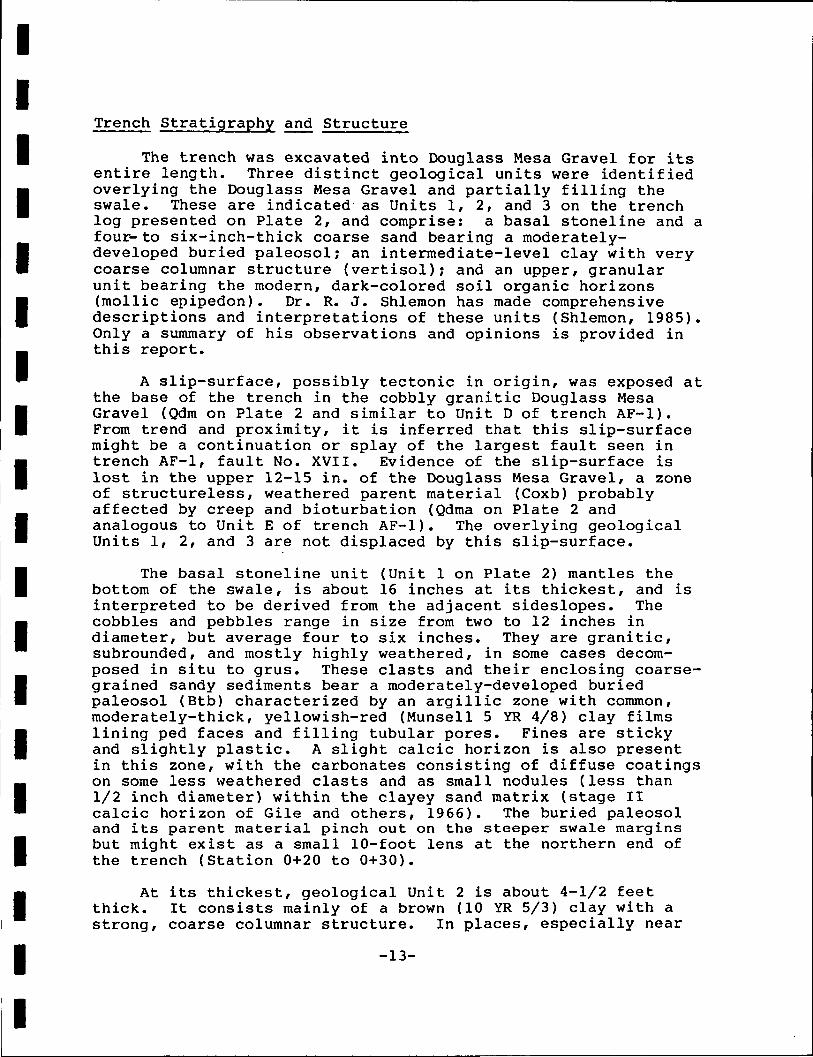
IIIIIIIIIIIIIIIIIII
Trench Stratigraphy and Structure
The trench was excavated into Douglass Mesa Gravel for itsentire length. Three distinct geological units were identifiedoverlying the Douglass Mesa Gravel and partially filling theswale. These are indicated as Units 1, 2, and 3 on the trenchlog presented on Plate 2, and comprise: a basal stoneline and afour- to six-inch-thick coarse sand bearing a moderately-developed buried paleosol; an intermediate-level clay with verycoarse columnar structure (vertisol); and an upper, granularunit bearing the modern, dark-colored soil organic horizons(mollic epipedon). Dr. R. J. Shlemon has made comprehensivedescriptions and interpretations of these units (Shlemon, 1985).Only a summary of his observations and opinions is provided inthis report.
A slip-surface, possibly tectonic in origin, was exposed atthe base of the trench in the cobbly granitic Douglass MesaGravel (Qdm on Plate 2 and similar to Unit D of trench AF-1).From trend and proximity, it is inferred that this slip-surfacemight be a continuation or splay of the largest fault seen intrench AF-1, fault No. XVII. Evidence of the slip-surface islost in the upper 12-15 in. of the Douglass Mesa Gravel, a zoneof structureless, weathered parent material (Coxb) probablyaffected by creep and bioturbation (Qdma on Plate 2 andanalogous to Unit E of trench AF-1). The overlying geologicalUnits 1, 2, and 3 are not displaced by this slip-surface.
The basal stoneline unit (Unit 1 on Plate 2) mantles thebottom of the swale, is about 16 inches at its thickest, and isinterpreted to be derived from the adjacent sideslopes. Thecobbles and pebbles range in size from two to 12 inches indiameter, but average four to six inches. They are granitic,subrounded, and mostly highly weathered, in some cases decom-posed in situ to grus. These clasts and their enclosing coarse-grained sandy sediments bear a moderately-developed buriedpaleosol (Btb) characterized by an argillic zone with common,moderately-thick, yellowish-red (Munsell 5 YR 4/8) clay filmslining ped faces and filling tubular pores. Fines are stickyand slightly plastic. A slight calcic horizon is also presentin this zone, with the carbonates consisting of diffuse coatingson some less weathered clasts and as small nodules (less than1/2 inch diameter) within the clayey sand matrix (stage IIcalcic horizon of Gile and others, 1966). The buried paleosoland its parent material pinch out on the steeper swale marginsbut might exist as a small 10-foot lens at the northern end ofthe trench (Station 0+20 to 0+30).
At its thickest, geological Unit 2 is about 4-1/2 feetthick. It consists mainly of a brown (10 YR 5/3) clay with astrong, coarse columnar structure. In places, especially near
-13-

IIIIIIIIIIIIIIIIIII
the swale margins, the unit incorporates lenses of clayey coarsesand and scattered granitic pebbles. Manganese stains arecommon on pressure faces but are thought to be derived from theoverlying Unit 3. Fine-to medium-sized roots are common. Thisclay unit is interpreted by Shlemon (1985) to be primary inorigin, deposited almost entirely from slopewash rather thanfrom pedogenesis. Shlemon also notes that accretionary swalefilling is indicated by the gradual-smooth lower contact withthe buried paleosol of Unit 1.
Geological Unit 3 attains a thickness of almost two feetbut thins considerably to each side of the swale. It is mainlya brown (7.5 YR 4/2 - 10 YR 5/3), fine granular clay loam (A ),similar to the mollic epipedon seen in trench AF-1. A cambic,or possibly weak argillic, horizon (Aj ) occurs in the lower sixinches of the unit. Other indistinct pedogenic horizons areprobably also present but were not differentiated. An abrupt-smooth lower contact separates this unit from clays of Unit 2.
Soil-Stratigraphic Age Assessment
Estimation of the age of undisplaced swale-filling sedi-ments exposed in trench AF-2 was accomplished by soil-stratigraphic and geomorphic assessment. The principal factorsinfluencing this assessment were:
1. The presence of a moderately-developed paleosol inUnit 1, indicating that the swale existed for perhapsthousands of years before slow accretionary swale-filling took place with deposition of Unit 2 clays;
2. The slow deposition of Unit 2 clays probably repre-sents a long period of time because the swale occurson a topographic divide and its drainage, or source,area is very limited;
3. The gradual-smooth contact between Unit 2 clays andthe buried paleosol of Unit 1 is indicative of slowaccretionary infilling;
4. The abrupt-smooth contact between Units 2 and 3 (prob-able unconformity) might reflect a regional climatic/sedimentologic change; and
5. Considerable time must have elapsed since depositionof the basal stoneline for many clasts to have decom-posed in situ to grus.
Upon evaluation of these factors and having conducted adetailed examination of the trench section, Dr. R. J. Shlemon
-14-

IIIIIIIIIIIIIIIIIII
concluded that the buried paleosol of Unit 1 and its coveringsediments represent about 30,000 to 50,000 years of weatheringand deposition (Shleraon, 1985). He also suggests that theburied paleosol may in fact be considerably older, comparing itto post-Louviers age soils, the parent material of which may beabout 100,000 years old.
SUMMARY AND CONCLUSIONS
The primary objectives of this study were to collect anddocument evidence, by geologic mapping and trenching, that couldbe related to the occurrence of faulting in the Air ForceAcademy study area and to assess the age of the latest movementon these faults.
The presence of faults in the study area as shown byprevious workers has been confirmed. The southeast-trendingsplay of the Rampart Range fault, which was the main object ofstudy, was however found to consist of a multiple fault zone intrench AF-1 and not a simple planar structure. It is recognizedthat the trench might not have covered the full width of thefault zone. The fault zone existed, wholly or in part, prior todeposition of the Quaternary Douglass Mesa Gravel. The faultsprobably formed as high-angle reverse structures in lateLaramide time as a result of compressional deformation. As muchas 2500 to 3000 feet of the Cretaceous bedrock section may havebeen faulted out.
Subsequent movements in Quaternary time resulted in dis-placements along the pre-existing faults exposed in the twotrenches and possibly the creation of new faults. These dis-placements are evidenced by offset of the overlying QuaternaryDouglass Mesa Gravel. Of critical importance to this study isthe assessment of the age of latest movement on the faults.This assessment takes into account the main findings of thefield investigations which are summarized below:
1. The site tectonic history involves Laramide reversefaulting and Quaternary normal faulting. The lattermight have been preceded by another tectonic episodeearly in Douglass Mesa time, as evidenced by anangular unconformity and provenance differences.
2. The age of the Douglass Mesa Gravel is estimated to beabout 600,000 years. Faults that displace this unitmust therefore be younger than 600,000 years old.
3. Only one of the several faults in trench AF-1 appearsto have any geomorphic expression. This is a topo-graphic swale on the Douglass Mesa Gravel surface and
-15-

IIIIIIIIIIIIIIIIIII
was interpreted previously as prima facie evidence ofQuaternary age faulting (Scott, 1970). It is assumedthat the youngest fault movement to occur in the areatook place on the fault underlying this swale.
4. Trench AF-2 was excavated into the swale-filling sedi-ments and exposed a buried paleosol and other soilhorizons extending undisplaced across the swale andoverlying a slip-plane at the base of the trench. Theburied paleosol and its covering sediments are inter-preted to represent about 30,000 to 50,000 years ofweathering and deposition/ and perhaps considerablymore (Shlemon, 1985).
5. Landsliding on the east side of the ridge causedtruncation of the swale and a reduction in the sourcearea for swale-filling sediments. This landslidingpost-dates formation of the swale (and the assumedcausative faulting) but pre-dates Husted Alluvium inthe valley to the east. Husted Alluvium is earlyHolocene in age, say 8,000 to 12,000 years old. Thelandslide deposits, therefore, could be considerablyolder.
6. Holocene alluvium is not apparently displaced wherethe Rampart Range fault splay (or splays) cross WestMonument Creek.
From the main findings outlined above it is concluded thatthe last displacement in the fault zone probably occurred on afault underlying the swale noted earlier by Scott (1970). Thismovement is judged to have taken place between about 600,000 and30,000 to 50,000 years ago. It is conceivable that latermovements may have occurred on other faults, some of which maynot have been trenched. This, however, is not considered likelybecause of the lack of geomorphic evidence in support of such anargument.
Although Quaternary faulting in the study area is notdenied, it should be noted that at least some of the observedoffsets in Quaternary deposits might be attributable to massmovements involving structurally weakened, weathered, and, insome cases, bentonitic, bedrock. Landsliding and slumpinginvolving the Pierre Shale is well-known in Colorado and in atleast one area has been interpreted as the origin of geomorphicfeatures previously attributed to tectonic faulting (West,1977).
-16-

IIIIIIIIIIIIIIIIIII
REFERENCES CITED
Finlay, G. I., 1916, Description of the Colorado Springs Quad-rangle (Colorado): U. S. Geological Survey Geol. Atlas,Folio 203, 17 p.
Gile, L. H.f Peterson, R. F., and Grossman, R. B., 1966, Morpho-logical and Genetic Sequences of Carbonate Accumulation inDesert Soils: Soil Science, v. 101, No. 5, pp. 347-360.
Harza Engineering Company, 1985, Regional Fault Study; Report A,ill Geotechnical Advisory Committee, Geologic and Seismo-tectonic Investigations, Second Interim Report - Part I:Denver Water Department, Denver, Colorado, 71 p.
Kirkham, R. M., and Rogers, W. P., 1981, Earthquake Potential inColorado - A Preliminary Evaluation: Colorado GeologicalSurvey Bulletin 43, 171 p.
Machette, M. N., Birkeland, P. W., Markos, G., and Guccione,M. J., 1976, Soil Development in Quaternary Deposits in theGolden-Boulder portion of the Colorado Piedmont, In Epis,R. C., and Weimer, R. J., eds., Studies in Colorado FieldGeology: Professional Contributions of Colorado School ofMines, No. 8, pp. 339-357.
Scott, G. R., 1970, Quaternary Faulting and PotentialEarthquakes in East-Central Colorado: U. S. GeologicalSurvey Professional Paper 700-C, pp. C11-C18.
Scott, G. R., and Wobus, R. A., 1973, Reconnaissance GeologicMap of Colorado Springs and vicinity, Colorado: U. S. Geo-logical Survey Map MF-482.
Shlemon, R. J., 1985, Soil-Geomorphic Assessment, Ken Caryl,Reynolds Park, and Air Force Academy Trench Sites, CentralFront Range, Colorado; Report D, in Geotechnical AdvisoryCommittee, Geologic and Seismotectonic Investigations,Third Interim Report: Denver Water Department, Denver,Colorado, 11 p.
Trimble, D. E., and Machette, M. N., 1979, Geologic Map of theColorado Springs-Castle Rock Area, Front Range Urban Corri-dor, Colorado: U. S. Geological Survey MiscellaneousInvestigation Series Map I-857-F.
Van Horn, Richard, 1976, Geology of the Golden Quadrangle,Colorado: U. S. Geological Survey Professional Paper 872,116 p.
-17-

IIIIIIIIIIIIIIIIIII
Varnes, D. J., and Scott, G. R. , 1967, General and EngineeringGeology of the United States Air Force Academy site,Colorado: U. S. Geological Survey Professional Paper 551,93 p.
Warner, L. A., 1985, Geotectonics of Central Colorado: implica-tions for stress distribution and seismic potential; ReportI, jji Geotechnical Advisory Committee, Geologic and Seismo-tectonic Investigations, Third Interim Report: DenverWater Department, Denver, Colorado.
West, W. , 1977, A Preliminary Evaluation of the QuaternaryGeology, Reported Surface Faulting, and Seismicity alongthe East Flank of the Gore Range, Summit County, Colorado:Colorado School of Mines, M.S. Thesis, T-1828.
-18-

IIIIIIIIIIIIIIIIIII
39'00' -
38'50' -
—?, .Palmer lake
i JDivide between South Platte-^ .
Jack Valley
oCathedral Rock
USAF ACADEMY
oodmen SidingCottomaood
5 MILESj I
Figure 1. Map showing location of U.S. Air Force Academy, El Paso County, Colorado(from Varnes and Scon, 1967, fig. 1).

IIIIIIIIIIIIIIIIIII
EXPLANATION
Qc .'•;Colluvium Husted Alluvium
Niobrara FormationKns, Smoky Hill Shale MemberKnf, for* Hays Limestone Member
Carlile Shale, Greenhorn IJmestone, and Graneros Shale
Dakota Sandstone
| Jm~]
Morrison Formation
Lykins Formation
400I
800 FEETI
ContactDashed where approximately located or inferred
__.
FaultDashed where approximately located; queried where doubtful;
Strike and dip of beds dotted where concealed. U, upthrown side; D, downthrown side
45
Figure 2. Geologic map of site area, from Scott (1970), showing approximatelocations of Trenches AF—1 and AF—2.

IIIIIIIIIIIIIIIIIII
FIGURES
Colorado Springsiltration Pla
EXPLANATION
GEOLOGIC UNITS
QUATERNARY<
TERTIARY-
CRETACEOUS<
JURASSIC <
PERMIAN//"TRIASSIC 1
PERMIAN <T
Artificial Fill
Colluvium
Husted Alluvium
Landslide
Douglass Mesa Gravel
Dawson Arkose
Laramie Formation
Fox Hills Sandstone
Pierre Shale
Niobrara Formation,Smokey Hill Shale Member
Niobrara Formation,Fort Hays Limestone Member
Carlile Shale, GreenhornLimestone, Graneros Shale
Dakota Sandstone
Morrison Formation
Lykins Formation
Lyons Sandstone
SYMBOLS
Geologic contact, dashedwhere approximately located
Fault, dashed where approximatelyi ? • • • located, dotted where concealed,
queried where uncertain
50 Strike and dip of beds
Strike and dip of overturned beds
Intermittent spring
Trench location
NOTES
1. Map modified from Scott (1970, fig.3)
2. Stratigraphy from Varnes and Scott (1967)
3. Topography from U.S. Air Force Academy
Scale 0I
100 200i
300 Meters
Scale 0 250 500 FeetI i I "
Figure 3. Revised geologic map of site area.
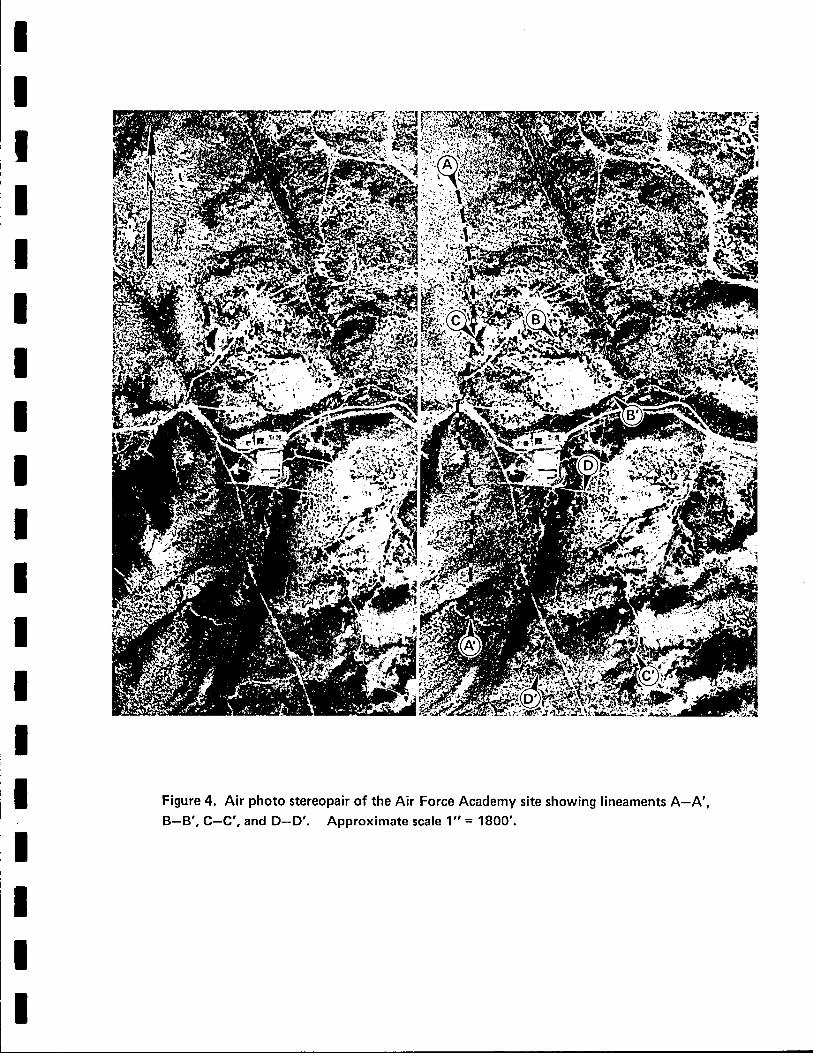
Figure 4. Air photo stereopair of the Air Force Academy site showing lineaments A—A',B-B', C—C', and D-D'. Approximate scale 1" = 1800'.

IIIIIIIIIIIIIIIIIII
SYSTEM & SERIES
Tertiary Paleocene
Upper
6
Lower
Jurassic
Triassic/Permian
Permian
Pennsylvanian
Ordovician
Cambrian
Precambrian
FORMATION
Dawson Arkose
Andesitic Lenses
Laramie Formation
Fox Hills Sandstone
Pierre Shale
Niobrara
Formation
Smoky Hill Sh.
Fort Hays Ls.
Carlile Sh., Greenhorn Ls.,Graneros Shale
Dakota Sandstone
Purgatoire Formation
Morrison Formation
Ralston Creek Formation
Lykins Formation
Lyons Sandstone
Fountain Formation
Glen Eyrie Sh.
Manitou Limestone
Sawatch Sandstone
Pikes Peak Granite
THICKNESS (ft.)
1000
185
2SO
250-320
5000
500
30
300
100
300
225
20
180
300
4400
100
280
25
From: Varnes and Scott (1967, fig.3)
Figure 5. Generalized stratigraphic column of bedrock units in site area.

TRENCH AF-1 N
7175 - -—
Ul
7185
7180
SYMBOLS
Top and Bottom of Trench Excava t i on .
Top of Bedrock.
Con tac ts of Geologic Units; queried where uncer ta in.
Faul ts , dashed where approx imate ; queried where inferred,
label led with roman numerals I -XXV.
PLATE2
~ 7 1 7 5
'W'"
Overburden Fabric, i.e. s t ra t i f icat ion, joints, bedding,
i/f'' A reas of Carbonate Accumulat ion.
7170 - -7170\\\\\\\
MnO Sta in ing .
7165 -7165
b .N29W
6 0 S W
i N 25 W56 S W
SDS
Str ike and Dip of Fau l t .
Str ike and Dip of Bedding.
Str ike and Dip of Jo int .
S l ickens ide with dipslip sense of movement
7160 -60 SW
-7160W"Z.0
l-CO
1-tu
Ol-
>UJ
UJ
ST
AT
ION
S
ro(O
+
1000
+CO
OO
10
I0
DAKOTA SANDSTONE, UNITS 1-14
Sil ty Sandstone: l ight g reen-gray , f ine-gra ined, f r iab le
C layey Sandstone: light green-gray, f ine-grained, f r iab le
Clayey and Si l ty Sandstone: light gray-green, fr iable
Si l ts tone: light to medium green-gray and gray-green
10
11
12
13
14
Clayey Si l tsone: mottled, gray-green and maroon red
Clayey and Sandy Siltstone: maroon red
Claystone: dark gray , mostly highly deformed, gouge- l ike
Sandstone: o f f -wh i t e to ye l low-gray, f ine-grained, f r iab le ,
with thin dark gray shale laminations, iron-stained
Sandstone: whi te to l ight green-gray, f ine-grained,
f r iab le , i ron-s ta ined
Sandstone: ye l low-gray to light brown, moderately
wel l -cemented, f ine —med-gra ined, i ron-stained
Sandstone Brecc ia : wi th green-gray sandy matr ix, i ron-s ta ined
Sandstone: green-ye l low, fine grained, fr iable, i ron -s ta ined .
Sandstone: of f white, f ine-grained, f r iable, i ron-sta ined.
Sandstone: l ight ye l l ow-g ray to white, f ine —med-gra ined.
BEDROCK UNITS
G R A N E R O S SHALE: UNITS 15-25:
15 Black Shale: f i ss i l e , sandy in part.
16 Sandstone: gray, ye l low-g ray , f ine-gra ined, f r iab le, with
thin black sha te laminat ions .
17 Clay Shale: medium to dark gray, i ronstone nodules,
yel low e f f l o rescence .
18 Sandstone: ye l low-gray , f i ne -g ra ined , f r iab le ,
19 Si t ty Sandstone: light to medium gray, f r i ab le ,
20 Sandy Si l ts tone: medium gray , orange i ron -s ta ins
21 Clayey and Sandy Silstone: dark-gray.
22 Benton i te : wh i te , l ight gray, ye l l ow gray.
23 Sandy Shale: medium g r a y , i ron-s ta ined , ye l low
ef f lo rescence , thin bentonite l aye rs .
24 Sandstone: whi te, l ight gray, yel low, f ine-gra ined, f r iab le,
thin black shale interbeds.
25 Sandy Shale: light to medium gray, g reen-g ray hues in p laces
EXPLANATION
(Trench AF-1)
P I E R R E SHALE: UNITS 26-27:
26 Sandy Shale: o l ive-brown, o l ive-gray , s l ight ly ca lcareous in
places, var iab ley sandy, c a l c a r e o u s concre t ions, possib le
phosphatic nodules, local ly foss i l i fe rous
27 Upper iron-stained, oxidized zone of Pierre Shale
TRENCH AF-2
7200
SW
7205
7195-
7190 u
-7200
UNIT 1
7 195
U N I T 2
7190
o+
,,/ /////''
OCM
+
O
SYMBOLS
Top and Bottom of Trench
Principal C o n t a c t s Between Uni ts .
Minor or Ind is t inct Contacts Between Units
Sl ip-Sur face, Probably Equivalent to Fault
XVI I observed in Trench AF-1 .
Area of Carbonate Accumula t ion .
O<O
NOTES:
1. Locat ion of Trench AF-2 shown on Figure 3.
2. S ta t ion ing advances f rom nor theast to southwest
1in
UNIT 3
~lOCD
+
NOTES:
1. Location of Trench AF-1 shown on Figure 3.
2. Stat ioning advances f rom south to north.
SURFICIAL DEPOSITS
DOUGLASS MESA GRAVEL
A-| Sandy Grave l : light pink, yel low-pink to orange; subrounded
to angular c l a s t s of grani te, dolomite, quar tz i te ; coarse
quar tzose and fe ldspathic sand matr ix, few other f ines, rare
c layey silt and sand lenses; mostly well-cemented wi th
carbonate, occasional CaCOg nodules; i ron-sta in ing common,
local ly fo rm ing binder; poor to moderate strat i f icat ion.
&2 Sandy Grave l : as for A, but more frequent and larger grani te
clasts up to 6"d ia r less sedimentary clasts, less carbonate
content, less wel l -cemented; poor strat i f icat ion, some f ines
in moderatley wel l -cemented layers.
B i Silty Grave l l y Sand: ye l low-green, o l ive-brown; grave l
dispersed and in smal l lenses; moderately wel l-cemented,
sl ight carbonate.
32 Silty G r a v e l l y Sand: as for B-j but yel low-pink, orange-brown,
light br ick- red; moderately wel l-cemented; clayey silt layers.
Silty Sandy Grave l : as for B-j and 62 but more gravel ;
ol ive-brown, orange-brown; less wel l-cemented.
Cl Cobbly Grave l : orange-brown, red-brown; subangular to
rounded c las ts of granite (up to V dia), coarse grave l l y sand
matr ix nearly all resul t ing from weather ing of granite; weak
cementat ion with sl ight ly cohesive f ines, Mn and Fe ox ides ;
poorly-to we l l -s t ra t i f ied .
C2 Cobbly Grave l : as for Cq but s l ight ly better cemented due to
red -b rown si l ty c lay and c layey s i t t in matr ix and layers ;
genera l l y moderate ly we l l - s t ra t i f i ed .
C3 Sandy G r a v e l : o range-brown, red-brown; w e l l - s t r a t i f i e d
coarse sand and pebbles or quartz and fe ldspa r .
D Cobbly Grave l : as for C, bouldery in p laces; weak cement;
s t r a t i f i ca t i on ind is t inct to absent.
E Cobbly and Bouldery G r a v e l : as for C and D; cementat ion very
weak, most ly d i f fuse i l luv ia ted clay and ox ides or iron and
manganese; no apparent sedimentary s t ra t i f i ca t ion , probably
largely not in situ, a f fec ted by creep, slumping, bioturbation.
G Grani te Boulder: commonly decomposed in situ to grus.
S Slump Deposit: mater ia ls var iable, la rge ly cons is t ing of
wea thered f ragmen ts of sedimentary bedrock uni ts occurr ing
immediate ly ad jacent or beneath; f ramework chaot ic w i th random
blocks in contac t wi th one another or in c layey sand mat r i x ; in
p laces over l i es apparent ly in si tu Douglass Mesa Grave l layers.
Note: prefix X indicates depositional unit has probably slumped at some time in past,
as determined from field relations and interval structures.
E X P L A N A T I O N
(Trench A F - 2 )
GEOLOGIC UNITS
Basal Stoneline Unit: cobbles and pebbles {2"-12" dia, average 4"-6"),
granit ic, subrounded, highly weathered, some decomposed in situ to grus;
c layey, coarse-gra ined sandy matr ix ; unit bears mode/ate ly-deve loped
buried paleosol (Btb} with ye l l ow- red (5YR 4/8) c lay f i lms; slight
ca lc i c hor izon consist ing of d i f fuse coat ings and small nodules (stage I I) .
Clay Laye r : thick brown (10YR 5/3) clay wi th s t rong columnar s t ructure,
non-pedogen ic , deposi ted by s lopewash (ve r t i so l ) ; includes lenses of c layey
coarse sand and dispersed gran i t ic pebbles; MnO stains common probably
der ived f rom ove r l y i ng unit ; gradual -smooth lower contact .
Modern Organic Hor i zons : brown (7 .SYR 4/2 to 10YR 5/3), f ine g ranu la r
c lay foam ( A - ) - ] ) ; combic or weak a rg i l t i c hor izon (A io ) occurs in lower
6"; may include other indist inct layers ; abrupt-smooth lower contact ,
probable unconformi ty .
Qdm
Qdma
Douglass Mesa Grave l : coarse, cobbly, gran i t ic g rave l
few f ines; weakly cemented; faint strat i f icat ion.
Douglass Mesa Gravel: zone of structureJess, highly
weathered cobbly g rave l .
SCALE 0 10 FEET
AAAANo. DESCRIPTION DATE BY
REVISIONS
AS CONSTRUCTED DATE; BY:
DENVER WATER DEPARTMENT
EAST SLOPE STORAGEGEOLOGY NOVEMBER 1985AIR FORCE ACADEMY SITETRENCH AF-1 AND AF-2
3)m•oO33H00
SCALE =
DRAWN:
DATE •• _________
CHECKED' __________
APPROVED __ „ _______DR ___ No. ____m10
SHEET OF SHEETSDCDBnnnr-rtruu rniuciii TAWTC

KX-tt
UJUJU.
zo
LU_JLU
COZoH<I-co
I-LUUJU.
OF<>UJ_iHI
COzo
co
.UJUJ
zOP
COzgP<CO
7200 n
7195 -
7190 -
7185 -
7180 -I
ORIGINAL GROUND LINE
f. N-SN 10W75W-90
SDS
b N 2 7 W
52 SW 49 sw
V j. N 50 E9 50 NW
SDS
- 7185
-7180
7195 -i
7190 -
7185 -
7180 J
7175 1
7170 J
MOLLIC EPIPEDON
D /-JydN ^ _ // ^
R - fc.1** "** n
35 NE XIf. N15W 22' \ — /
55W xi|Uf-N17W XIIIb.j. N40W
47 W b N_s xtvb.N25W - 57
48 SW 60Wf. N 30 W42 SW
b. N 16 E54 W
f. N13E53 W
r 7195
^ 7190
- 7185
- 7180
10
- 7175
55 W -7170
roCM
O
+
o<o
o00
oo
<M
OCM
CM
no•«*•I-
CM
7190 -i
7185 -
7180 -
3 7175-
7170 -
7165-
MOLLIC EPIPEDON
CONCRETION
f. N 23 W
60 SW
). N 30 Ej. N 60 E 75 SE
75 -80 N W
b. N 41 W49 SW
b. N 37 W - '
53 SW b. N 35 W45 SW
i.b. IM 10 W
50-63 SW b. N 35 W50 s w
XVIIIN30W
f. N 36 W55 SW
f. N 30-34 W50 SW
b. N 35 W50 SW
j.b. N 10W75 W
j . N 7 5 E80 NW Slip planes
N 20-30 E25-60 SE
IXXN35 W51 SW
f. N 26 W50 SW
r 7185
-7180
- 7175
- 7 1 7 0
^7165
rO
ICM
OCO
CM
OCO
01
oo
CO
oCM
05•*•
CO
OCO
•*-CO
AAAANO. DESCRIPTION DATE
PLATE 1
NOTES:
1. For Explanation see PLATE 2.
2. Location of Trench AF-1 shown on Figure 4
3. Stationing advances from south to north.
SCALE 0 10 FEET
BY
REVISIONS
AS CONSTRUCTED DATE; BY:
DENVER WATER DEPARTMENTEAST SLOPE STORAGEGEOLOGY NOVEMBER 1985
AIR FORCE ACADEMY STUDY AREATRENCH AF-1
SCALE--
DRAWN:
DATE:_.
CHECKED^
APPROVED^ . DR No.
mTJODOH
I
•o
Hm
SHEET OF SHEETS
REPRODUCTION CONSULTANTS LTD.