hysweep® drivers - hypack, inc. library/resource library/driver interfacing... · hypack...
TRANSCRIPT

HYSWEEP® Drivers
Interfacing Notes
56 Bradley St. Phone: 1-860-635-1500
Middletown, CT 06457 Fax: 1-860-635-1522
USA Tech. Support: [email protected]
www.hypack.com
January / 2017 1

2
HYSWEEP Survey Interfacing Notes
Table of Contents:
Table of Contents: .......................................................................................................................................... 1 Update History: .............................................................................................................................................. 3 Analog Sidescan ............................................................................................................................................. 4 Applanix POS MV Network........................................................................................................................... 5 Applanix POS/MV Serial ............................................................................................................................... 7 Atlas Bomasweep ........................................................................................................................................... 8 Atlas Fansweep (Network), Hydrosweep MD2 (HYPACK 2009A and Earlier) ........................................... 9 Atlas Fansweep, Hydrosweep MD2, MD/30, MD/50, DS (HYPACK 2010 and Later) .............................. 10 Atlas Fansweep (Serial) ................................................................................................................................ 12 BlueView BV5000 ....................................................................................................................................... 13 BlueView Multibeam ................................................................................................................................... 14 Benthos C3D ................................................................................................................................................ 15 Coda-Octopus F180 ...................................................................................................................................... 16 Edgetech 4600/6205 ..................................................................................................................................... 17 FURUNO HS Series Multibeam .................................................................................................................. 18 Generic Attitude ........................................................................................................................................... 19 GeoAcoustics GeoSwath .............................................................................................................................. 20 HYPACK Navigation ................................................................................................................................... 21 Imagenex Delta T ......................................................................................................................................... 22 Imagenex Delta T – Dual Head .................................................................................................................... 23 Imagenex DT100 SIR ................................................................................................................................... 24 IS Tech Multibeam ....................................................................................................................................... 25 IXSEA Octans Network ............................................................................................................................... 26 IXSEA Octans Serial .................................................................................................................................... 27 JAE JM7531 MRU ....................................................................................................................................... 28 Klein HydroChart 3500 ................................................................................................................................ 29 Klein 5000 .................................................................................................................................................... 30 Kongsberg MS 1000 Profiler ........................................................................................................................ 31 KVH Gyrotrac .............................................................................................................................................. 32 MDL Dynascan laser .................................................................................................................................... 33 NMEA Gyro ................................................................................................................................................. 35 Novatel SPAN .............................................................................................................................................. 36 Odom Echoscan II ........................................................................................................................................ 37 Odom ES3 .................................................................................................................................................... 38 Odom ES3 – Dual Head ............................................................................................................................... 39 Odom MB1 ................................................................................................................................................... 40 Odom MB1 – Dual Head .............................................................................................................................. 41 Odom Miniscan ............................................................................................................................................ 42 Optech ILRIS 3D .......................................................................................................................................... 43 Picotech PicoMBES ..................................................................................................................................... 45 PingDSP 3DSS-DX ...................................................................................................................................... 46 R2Sonic Dual Head ...................................................................................................................................... 47 R2Sonic SONIC 2024 .................................................................................................................................. 48 R2Sonic SONIC 2024 (Seabat 81P compatible mode) ................................................................................ 49 Renishaw SLM laser ..................................................................................................................................... 50 RIEGL LMS Series laser .............................................................................................................................. 51 RIEGL V Series laser ................................................................................................................................... 52 Reson Dual 7125 .......................................................................................................................................... 54 Reson Dual 8101 (NY) ................................................................................................................................. 55 Reson Seabat 7101, 7125, 7150, 7160, 8125H, T20-P ................................................................................. 56
Reson Seabat 8101 ....................................................................................................................................... 58 Reson Seabat 81xx (Network) ...................................................................................................................... 59 Reson Seabat 81xx (Serial) .......................................................................................................................... 60 Reson Seabat 9001 / 9003 ............................................................................................................................ 61 Ross Smart Sweep ........................................................................................................................................ 62 Seabeam 1000 Series .................................................................................................................................... 63 Seabeam 2100 ............................................................................................................................................... 65 Seabeam 3000 Series .................................................................................................................................... 66 Simrad EM3000 ........................................................................................................................................... 67 Simrad EM1002, EM2000, EM2040, EM3002/D, EM302, EM710 ............................................................ 68 Simrad ME70 ............................................................................................................................................... 70 Simrad SM2000 ............................................................................................................................................ 71 Seatex MRU6 ............................................................................................................................................... 72 SG Brown 1000S Gyro ................................................................................................................................. 73 SEA SWATHplus ......................................................................................................................................... 74 Tritech Gemini Profiler ................................................................................................................................ 75 Tritech SeaKing ............................................................................................................................................ 76 TSS 335 ........................................................................................................................................................ 78 TSS DMS ..................................................................................................................................................... 79 TSS POS/MV ............................................................................................................................................... 80 Velodyne HDL-32E & VLP-16 .................................................................................................................... 81 WASSP Multibeam ...................................................................................................................................... 83 Appendix A: Analog Sidescan Interfacing .................................................................................................. 84 Appendix B: A Short List of Odd Things about HYSWEEP Interfacing ..................................................... 86 Appendix C: Interferometry Real-Time Processing ..................................................................................... 87
Update History: • January, 2017 Added Leica P20 section • May, 2016 Added Klein 5000, Tritech Gemini, Picotech sections. • April, 2015 Updated Optech section. Added PingDSP & Velodyne sections. • February, 2015 Added ME70. Few minor changes to MDL, Edgetech 6205. • March, 2014 Check and update notes for various drivers. • December, 2013 Updated setup form in Reson Seabat drivers. • August, 2013 Add Novatel section. Add Klein 3500 section. • July, 2013 Add R2Sonic Dual Head, Seabat 7160. Update Odom MB1 Dual Head. • June, 2013 Revise Simrad and MDL sections • April, 2013 Revise RIEGL and R2Sonic (TruePix) sections • April, 2013 Add Odom MB1 dual head and Imagenex DT100. • June, 2011 Add Odom MB1 section. Update Blueview section per driver changes. • September, 2010 Added RIEGL V Series section • April, 2010 Added Kongsberg MS 1000 section • March, 2010 R2Sonic driver update. • November, 2009 Update Swathplus, C3D, GeoSwath, Edgetech 4600. Add Appendix C. • August, 2009 Include R2Sonic driver. • December, 2008 Include FURUNO and JAE drivers. • October, 2008 Additional notes on Delta T / ES3. Dual head Delta T / ES3. Seabat 7101. • September, 2008 POS/MV network updates. • April, 2008 Seabat 7125 driver changes. • March, 2008 Update Benthos section for new driver • March, 2008 Include Seabat 7125 dual head and BlueView multibeam • January, 2008 Restore missing RIEGL LMS-Q120 section. • November, 2007 Include Simrad EM710 and EM302 drivers. Updates to Atlas drivers. • January, 2007 Include Simrad EM3002D driver. • November, 2006 Include POS/MV and Delta T drivers. • August, 2006 Include Coda-Octopus F180. • December, 2005 Include Reson Seabat 7125. • August, 2005 Additional notes on Tritech Sea King. • March, 2005 Include GeoAcoustics GeoSwath. • November, 2004 Include Simrad EM3002.

Analog Sidescan Driver providing 2-channel sidescan information from analog input. A separate program (Ascan.exe) is run automatically to sample the ping trigger and digitize the analog inputs. The digitized data are passed to HYSWEEP Survey through shared memory. Setup Form: The is no setup form in HYSWEEP Hardware. However, clicking “Analog Sidescan Monitor” (on the taskbar) during HYSWEEP Survey will show the following form for sidescan configuration on the fly. Input: Select one of the voltage range options. Trigger: Ping is on low to high or high to low transition of the trigger signal. Gain: Gain constant (voltage multiplier). Threshold: This is the A/D count level at which trigging occurs. Test: Simulate data provides a dummy amplitude time series for each channel. Connection: Connected via a National Instruments multifunction I/O device – PCI board or PCMCIA card. The device is plug and play – no configuration required. Offsets – Sonar Heads 1 and 2:
• Starboard: Sonar head locations starboard of boat center. • Forward: Sonar head locations forward of boat center. • Vertical: Sonar head locations relative to waterline (positive). • Yaw, Pitch, Roll. Latency: Enter 0.
Notes: See Appendix A: Analog Sidescan Interfacing.
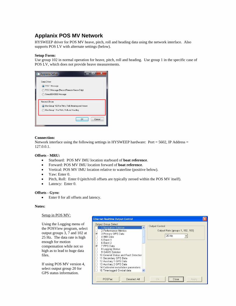
Applanix POS MV Network HYSWEEP driver for POS MV heave, pitch, roll and heading data using the network interface. Also supports POS LV with alternate settings (below). Setup Form: Use group 102 in normal operation for heave, pitch, roll and heading. Use group 1 in the specific case of POS LV, which does not provide heave measurements.
Connection: Network interface using the following settings in HYSWEEP hardware: Port = 5602, IP Address = 127.0.0.1. Offsets - MRU:
• Starboard: POS MV IMU location starboard of boat reference. • Forward: POS MV IMU location forward of boat reference. • Vertical: POS MV IMU location relative to waterline (positive below). • Yaw: Enter 0. • Pitch, Roll: Enter 0 (pitch/roll offsets are typically zeroed within the POS MV itself). • Latency: Enter 0.
Offsets - Gyro:
• Enter 0 for all offsets and latency. Notes:
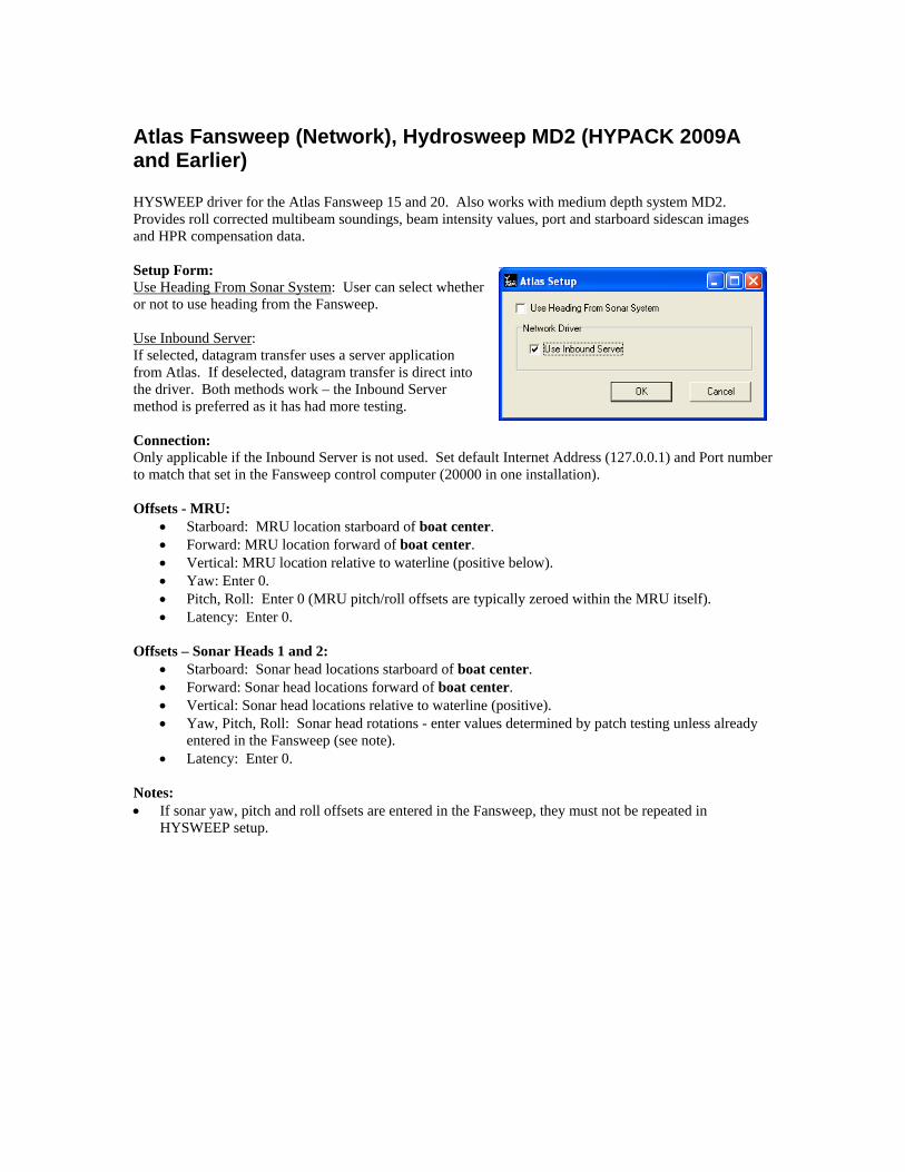
Setup in POS MV: Using the Logging menu of the POSView program, select output groups 3, 7 and 102 at 25 Hz. The data rate is high enough for motion compensation while not so high as to lead to huge data files. If using POS MV version 4, select output group 20 for GPS status information.
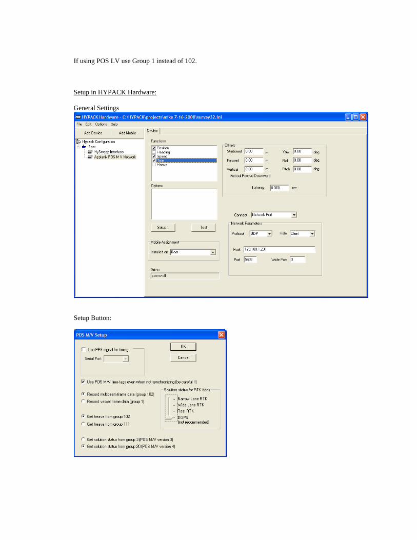
If using POS LV use Group 1 instead of 102. Setup in HYPACK Hardware: General Settings
Setup Button:

Applanix POS/MV Serial HYSWEEP driver for POS/MV heave, pitch, roll and heading data using serial interface. Setup Form:
Select TSS 1 Message for the text output message – heave, pitch and roll string similar to the DMS/05. Select TSS 3 Message to record remote heave instead of total heave as with the TSS1 message. Select Simrad EM3000 Message for binary output containing heave, pitch, roll and heading. Connection: RS232 Serial interface. Offsets - MRU:
• Starboard: MRU location starboard of boat center. • Forward: MRU location forward of boat center. • Vertical: MRU location relative to waterline (positive below). • Yaw: Enter 0. • Pitch, Roll: Enter 0 (MRU pitch/roll offsets are typically zeroed within the MRU itself). • Latency: Enter 0.
Offsets - Gyro:
• Enter 0 for all offsets and latency. Notes:
• Supersedes TSS POS/MV driver.

Atlas Bomasweep Driver providing heading and depth from a 41 transducer system. Setup Form: Heading from the Bomasweep is optional. Connection: RS232 Serial interface. Message record is shown below. SZ7202 10125471 00000000000 000000000 000000 127500 000000 0000 0001 000 00 00211 033 000 00318 1 00319 1 00320 1 00315 1 00300 1 00310 1 00305 1 00305 1 00297 1 00277 1 00273 1 00279 1 00286 1 00289 1 00286 1 00293 1 00300 1 00314 1 00320 1 00332 1 00343 1 00347 1 00351 1 00372 1 00380 1 00388 1 00401 1 00403 1 00409 1 00427 1 00423 1 00426 1 00430 1 00435 1 00432 1 00438 1 00428 1 00451 1 00444 1 00424 1 00404 1 Offsets - Heading: All heading offsets are 0 with the exception of Yaw, which is based on the patch test results. Offsets – Transducers 1 through 41:
• Starboard: Transducer position starboard of boat center. • Forward: Transducer position forward of boat center. • Vertical: Transducer draft (positive). • Yaw, Pitch, Roll: All zeros. • Latency: Enter the latency time (positive, seconds) appropriate for each transducer.
Notes:
Atlas Fansweep (Network), Hydrosweep MD2 (HYPACK 2009A and Earlier) HYSWEEP driver for the Atlas Fansweep 15 and 20. Also works with medium depth system MD2. Provides roll corrected multibeam soundings, beam intensity values, port and starboard sidescan images and HPR compensation data. Setup Form: Use Heading From Sonar System: User can select whether or not to use heading from the Fansweep. Use Inbound Server: If selected, datagram transfer uses a server application from Atlas. If deselected, datagram transfer is direct into the driver. Both methods work – the Inbound Server method is preferred as it has had more testing. Connection: Only applicable if the Inbound Server is not used. Set default Internet Address (127.0.0.1) and Port number to match that set in the Fansweep control computer (20000 in one installation). Offsets - MRU:
• Starboard: MRU location starboard of boat center. • Forward: MRU location forward of boat center. • Vertical: MRU location relative to waterline (positive below). • Yaw: Enter 0. • Pitch, Roll: Enter 0 (MRU pitch/roll offsets are typically zeroed within the MRU itself). • Latency: Enter 0.
Offsets – Sonar Heads 1 and 2:
• Starboard: Sonar head locations starboard of boat center. • Forward: Sonar head locations forward of boat center. • Vertical: Sonar head locations relative to waterline (positive). • Yaw, Pitch, Roll: Sonar head rotations - enter values determined by patch testing unless already
entered in the Fansweep (see note). • Latency: Enter 0.
Notes: • If sonar yaw, pitch and roll offsets are entered in the Fansweep, they must not be repeated in
HYSWEEP setup.

Atlas Fansweep, Hydrosweep MD2, MD/30, MD/50, DS (HYPACK 2010 and Later) HYSWEEP driver for Atlas multibeam systems. Provides roll and possibly pitch corrected soundings, beam intensity values, port and starboard sidescan images and HPR and heading data. The Fansweep and Hydrosweep MD2 are roll corrected. The Hydrosweep MD/30, MD/50 and DS are roll and pitch corrected. Setup Form: Use Heading From Sonar System: User can select whether or not to use heading from the multibeam system. Connection: HYSWEEP does not have a direct serial or network connection to the multibeam system. Instead, the connection is via software provided by Atlas.
1. HMCOM.DLL 2. UDPInboundServer (Windows Service).
Atlas install files are available from Rolf Alfke ([email protected]). Offsets - Heading:
• Yaw: Enter the heading correction, or zero if no correction.
Offsets - MRU: • Starboard: MRU location starboard of boat center. • Forward: MRU location forward of boat center. • Vertical: MRU location relative to waterline (positive below). • Yaw: Enter 0. • Pitch, Roll: Enter 0 (MRU pitch/roll offsets are typically zeroed within the MRU itself). • Latency: Enter 0.
Offsets – Sonar Heads 1 and 2:
• Starboard: Sonar head locations starboard of boat center. • Forward: Sonar head locations forward of boat center. • Vertical: Sonar head locations relative to waterline (positive below). • Yaw – Enter value determined by patch testing. • Pitch – Enter value determined by patch testing unless already entered in Atlas Hydromap. • Roll – Enter zero in HYSWEEP. Roll correction is always entered in Atlas Hydromap. • Latency: Enter 0.
Notes: • Make sure not to enter yaw, pitch and roll offsets in both HYSWEEP and Hydromap. One or the
other. • Do not worry about double correcting for roll and pitch. That’s taken care of.
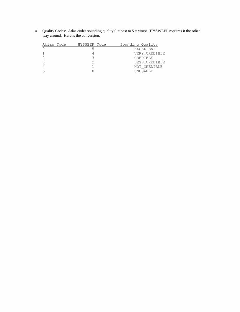
• Quality Codes: Atlas codes sounding quality 0 = best to 5 = worst. HYSWEEP requires it the other way around. Here is the conversion.
Atlas Code HYSWEEP Code Sounding Quality 0 5 EXCELLENT 1 4 VERY_CREDIBLE 2 3 CREDIBLE 3 2 LESS_CREDIBLE 4 1 NOT_CREDIBLE 5 0 UNUSABLE

Atlas Fansweep (Serial) Driver providing depth and HPR compensation from the Fansweep multibeam using a serial interface. This driver will eventually be replaced by a network driver. Setup Form: No specific setup for this driver. Connection: RS232 Serial interface. Message data is binary. Offsets - MRU:
• Starboard: MRU location starboard of boat center. • Forward: MRU location forward of boat center. • Vertical: MRU location relative to waterline (positive below). • Yaw, Pitch, Roll: MRU rotations relative to forward and vertical. • Latency: Enter the MRU latency time if any - positive, seconds.
Offsets – Sonar Head
• Starboard: Sonar head location starboard of boat center. • Forward: Sonar head location forward of boat center. • Vertical: Sonar head location relative to waterline (positive). • Yaw, Pitch, Roll: Sonar head rotations relative to forward and vertical. Enter values determined
by patch testing. • Latency: Enter 0 – latency is automatically compensated.
Notes:

BlueView BV5000 The BV5000 is a 3D scanning sonar with pan & tilt capabilities. Because of the pat & tilt nature and the relatively short range of the device, the data is logged as XYZI as if from a laser device. Connection: TCP Network connection. The address and port are configurable in the BlueView ProScan software. The driver communicates with ProScan which must be running at the same time as HYSWEEP. Notes: Below are screenshots of how to configure ProScan properly for GPS time sync and network communication:
BlueView Multibeam HYSWEEP driver for Blue View Technology multibeam systems. A number of systems are supported by this driver; MB1350-90, MB2250-90, etc. Connection: TCP Network connection. • Port – Use 7000. • Internet Address – Address of BVT controller. Notes: Device Control is no longer available.
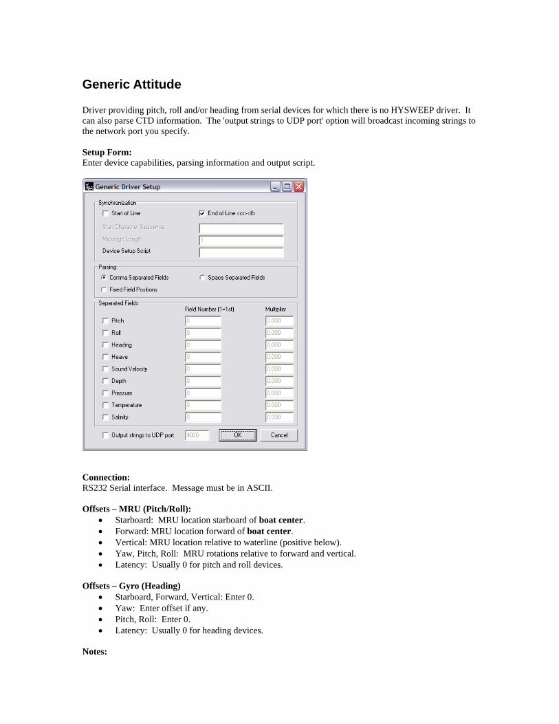
Benthos C3D HYSWEEP driver for the C3D Multibeam / Sidescan device. Provides multibeam soundings, beam intensity values and sidescan. Connection: All data is via a network interface. Internet address was pre-defined in previous driver version (pre HYPACK 2008). Now, internet address is configurable. Typically, it will be 127.0.0.1, but it could be different if the C3D Control Panel is run on a different computer. Port numbers are hard-coded in the driver so the 'port' field is ignored. However, note that the port number used is different for pole-mounted and towed systems so be sure to set the 'On Towfish' option in Hardware correctly. Setup Form: Each ping, the C3D sends thousands of range / angle / amplitude samples to HYSWEEP survey. These are reduced to a manageable number of beams in HYSWEEP Survey using the filtering and downsampling routines available in the HYSWEEP Interferometry window (See Appendix C). K8E format files can be logged alongside HSX by checking the “Record Raw Message” option on the Connect tab. By default the driver will read motion and CTD data coming from the C3D via separate UDP messages. However, if motion data should be read from the ping header, check the appropriate option in the set up form. If the C3D is pole-mounted, the Generic Attitude parser should be used to handle the CTD data coming into HYPACK via a serial connection. The C3D expects this CTD data to be relayed back via UDP port 4020 by the Generic Attitude parser (see the Generic Attitude parser section for more information). Offsets – Sonar Heads 1 and 2:
• Starboard: Sonar head locations starboard of boat center. • Forward: Sonar head locations forward of boat center. • Vertical: Sonar head locations relative to waterline (positive). • Yaw, Pitch, Roll: Sonar head rotations - enter values determined by
patch testing. • Latency: Enter 0.
Notes: At some point in 2008, Benthos changed how the C3D reports timing information. C3D users should make sure their sonar is up to date with Benthos and use HYSWEEP.exe/swpware.exe version 9.0.9 or later to be sure pings are timetagged properly.

Coda-Octopus F180 Provides heave, pitch, roll and heading via a network interface. Setup Form: The driver takes in data at 100 Hz. Even in the most extreme pitch and roll condition, 25 Hz sampling should be sufficient and you can decrease file size by selecting the 25 Hz option.
Connection: Network connection. Use 3000 for network port and the default internet address of 127.0.0.1. The F180 address is 195.0.0.180 and your network card must have an address that will receive data (195.0.0.181 for example)
Offsets – MRU (Pitch/Roll):
• Starboard: MRU location starboard of boat center. • Forward: MRU location forward of boat center. • Vertical: MRU location relative to waterline (positive below). • Yaw, Pitch, Roll: MRU rotations relative to forward and vertical. • Latency: Enter 0.
Offsets – Gyro (Heading)
• Enter 0 for all. Notes:
• When using this driver in HYSWEEP, it is likely the F180 network driver will be used in HYPACK survey. The F180 driver requires a 1PPS box for time synchronization.
• To use delayed heave, start logging in the F180 controller at least 10 minutes before any HYPACK / HYSWEEP logging. When finished surveying, use the F180 option to stop logging after iHeave delay. The *.CSV files are used for heave corrections; *.MCOM files may be deleted.

Edgetech 4600/6205 HYSWEEP driver for the Edgetech 4600 interferometer. Provides multibeam soundings, beam intensity, beam quality, and sidescan imagery. HYSWEEP also reads mru and gyro data from the Edgetech data stream. There is also a sister driver to read navigation from Edgetech in HYPACK called nav4600.dll. This allows all data from Edgetech to be timetagged by Edgetech. Connection: All data is via a network interface (TCP). Set the Internet Address to the IP of the multibeam. Set the port to 1900--the control port. The driver also uses port 1901 for data. The nav4600.dll driver mentioned above should be set to port 1902. Edgetech broadcasts navigation only on this port. Offsets:
• Starboard: Sonar head locations starboard of boat reference. • Forward: Sonar head locations forward of boat reference. • Vertical: Sonar head locations relative to waterline (positive). • Yaw, Pitch, Roll: Sonar head rotations - enter values determined by patch testing. • Latency: Enter 0.
Notes: This is the first driver to use new the Interferometry interface in HYSWEEP. The interface intends to standardize the filtering and downsampling/binning routines used on such data. Modify the processing settings with the Interferometry window from the View menu.

FURUNO HS Series Multibeam HYSWEEP driver for the FURUNO HS-300F, HS-600, and HS-600F multibeams. Provides multibeam soundings, beam intensity values and sidescan imagery. FURUNO provides a beam quality number between 0--3. Connection: All data is via a network interface (TCP). Set the Internet Address to the IP of the multibeam. The default port is 9000. Offsets:
• Starboard: Sonar head locations starboard of boat reference. • Forward: Sonar head locations forward of boat reference. • Vertical: Sonar head locations relative to waterline (positive). • Yaw, Pitch, Roll: Sonar head rotations - enter values determined by patch testing. • Latency: Enter 0.
Notes:
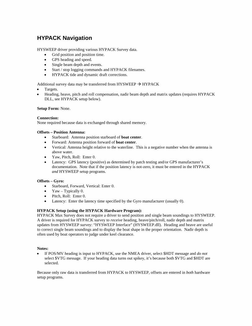
Generic Attitude Driver providing pitch, roll and/or heading from serial devices for which there is no HYSWEEP driver. It can also parse CTD information. The 'output strings to UDP port' option will broadcast incoming strings to the network port you specify. Setup Form: Enter device capabilities, parsing information and output script.
Connection: RS232 Serial interface. Message must be in ASCII. Offsets – MRU (Pitch/Roll):
• Starboard: MRU location starboard of boat center. • Forward: MRU location forward of boat center. • Vertical: MRU location relative to waterline (positive below). • Yaw, Pitch, Roll: MRU rotations relative to forward and vertical. • Latency: Usually 0 for pitch and roll devices.
Offsets – Gyro (Heading)
• Starboard, Forward, Vertical: Enter 0. • Yaw: Enter offset if any. • Pitch, Roll: Enter 0. • Latency: Usually 0 for heading devices.
Notes:

GeoAcoustics GeoSwath HYSWEEP driver for the GeoSwath multibeam / sidescan device. Provides multibeam soundings, beam intensity values and sidescan imagery. Setup Form: Each ping, the GeoSwath sends thousands of range / angle / amplitude samples to HYSWEEP survey. These are reduced to a manageable number of beams in HYSWEEP Survey using the filtering and downsampling routines available in the HYSWEEP Interferometry window (See Appendix C). RDF format files can be logged alongside HSX by checking the “Record Raw Message” option on the Connect tab. Connection: All data is via a network interface. Internet address can be left as 127.0.0.1. Use network port 5001. In 2010, the filtering features from the IFFilter program are built into HYSWEEP so this program is no longer needed for real-time operation. Offsets - MRU:
• Starboard: MRU location starboard of boat reference. • Forward: MRU location forward of boat reference. • Vertical: MRU location relative to waterline (positive below). • Yaw, Pitch, Roll: Enter MRU calibration offsets if not enetered elsewhere. • Latency: Enter 0.
Offsets - Gyro:
• Starboard, Forward, Vertical: Enter 0. • Yaw: Typically 0. • Pitch, Roll, Latency: Enter 0.
Offsets – Sonar Heads 1 and 2:
• Starboard: Sonar head locations starboard of boat reference. • Forward: Sonar head locations forward of boat reference. • Vertical: Sonar head locations relative to waterline (positive). • Yaw, Pitch, Roll: Sonar head rotations - enter values determined by patch testing. • Latency: Enter 0.
Notes: • Two computers are required; One runs GeoSwath +, which is the control program. The other runs
HYPACK / HYSWEEP. Communication is over the Ethernet cable. • The computers must be time synchronized. This is done by time synchronizing both to GPS time
(requiring a HYPACK 1PPS box). • in HYSWEEP 10.0.13 and later, the driver supports the 500kHz GeoSwath as well. It will attempt to
detect the frequency, but you can force this mode by setting Geo500kHz=1 in the section for the GeoSwath of your HYSWEEP.ini.
HYPACK Navigation HYSWEEP driver providing various HYPACK Survey data.
• Grid position and position time. • GPS heading and speed. • Single beam depth and events. • Start / stop logging commands and HYPACK filenames. • HYPACK tide and dynamic draft corrections.
Additional survey data may be transferred from HYSWEEP HYPACK • Targets. • Heading, heave, pitch and roll compensation, nadir beam depth and matrix updates (requires HYPACK
DLL, see HYPACK setup below). Setup Form: None. Connection: None required because data is exchanged through shared memory. Offsets – Position Antenna:
• Starboard: Antenna position starboard of boat center. • Forward: Antenna position forward of boat center. • Vertical: Antenna height relative to the waterline. This is a negative number when the antenna is
above water. • Yaw, Pitch, Roll: Enter 0. • Latency: GPS latency (positive) as determined by patch testing and/or GPS manufacturer’s
documentation. Note that if the position latency is not-zero, it must be entered in the HYPACK and HYSWEEP setup programs.
Offsets – Gyro:
• Starboard, Forward, Vertical: Enter 0. • Yaw – Typically 0. • Pitch, Roll: Enter 0. • Latency: Enter the latency time specified by the Gyro manufacturer (usually 0).
HYPACK Setup (using the HYPACK Hardware Program): HYPACK Max Survey does not require a driver to send position and single beam soundings to HYSWEEP. A driver is required for HYPACK survey to receive heading, heave/pitch/roll, nadir depth and matrix updates from HYSWEEP survey: “HYSWEEP Interface” (HYSWEEP.dll). Heading and heave are useful to correct single beam soundings and to display the boat shape in the proper orientation. Nadir depth is often used by boat operators to judge under keel clearance. Notes: • If POS/MV heading is input to HYPACK, use the NMEA driver, select $HDT message and do not
select $VTG message. If your heading data turns out spikey, it’s because both $VTG and $HDT are selected.
Because only raw data is transferred from HYPACK to HYSWEEP, offsets are entered in both hardware setup programs.

Imagenex Delta T HYSWEEP driver for the Delta T multibeam. Provides multibeam soundings via a network interface. Setup Form: There are two methods of time tagging Delta T data; (1) PC arrival time or (2) UTC time. The arrival time method works fine but for more accurate time tags select the UTC method. If UTC time is used, auxiliary sensors (GPS, MRU, gyro) must be time synched to UTC also. Connection: All data is via a network interface. Set network card internet address 192.168.0.4, subnet mask 255.255.255.0. Set HYSWEEP connection as shown:
Sonar Offsets:
• Starboard: Sonar head locations starboard of boat reference. • Forward: Sonar head locations forward of boat reference. • Vertical: Sonar head locations relative to waterline (positive). • Yaw, Pitch, Roll: Sonar head rotations - enter values determined by patch testing. • Latency: Enter 0.
Notes: • Two computers are required; One runs the Delta T multibeam, the other runs HYPACK / HYSWEEP.
Communication is over the Ethernet cable. • Both computers must be time synchronized to UTC time if Delta T UTC time tagging is selected. • The MRU should be connected to both computers. The Delta T does real-time roll corrections and
provides roll corrected data. HYSWEEP needs the pitch and heave corrections. • It is very easy to change the number of Delta T beams. Don’t do it. Select the number you like (120
or 240, 480 seems excessive in shallow water) and stick with it throughout the survey. Changing sector size also changes number of beams. If you do change the number of beams, you will need to fix number of beams to 480 in MBMAX post-processing (Advanced Read Parameters).

Imagenex Delta T – Dual Head HYSWEEP driver for the dual head Delta T multibeam. All setup information for single head delta T applies with the exceptions: Sonar Offsets: Since there are two sonar heads, two sets of offsets that must be entered.

Imagenex DT100 SIR HYSWEEP driver for the DT100 multibeam using SIR (Sensor Input Relay). Sonar, motion and heading data are time tagged and routed to HYSWEEP via the SIR. Setup Form: No specific setup required. Connection: Use Network Port 4040. Use Internet Address 127.0.0.1 or address of the SIR. Offsets: • Sonar Head 1 – Enter sonar head location relative to boat reference. Enter patch test offsets. Latency
should be 0. • MRU Offsets – Enter MRU location relative to boat reference. • Heading Offset (Yaw) – Enter yaw angle if needed for boat heading adjustment.
Notes: • The SIR interface can be used with a Delta T as well as with DT100 sonar. When Delta T is connected
via SIR, use this (not Delta T) driver.

IS Tech Multibeam Provides multibeam soundings and side scan via a network interface. Setup Form: None. Connection: All data is via a network interface. Set network card internet address and port to the sonar. Sonar Offsets:
• Starboard: Sonar head locations starboard of boat reference. • Forward: Sonar head locations forward of boat reference. • Vertical: Sonar head locations relative to waterline (positive). • Yaw, Pitch, Roll: Sonar head rotations - enter values determined by patch testing. • Latency: Enter 0.
Notes: •

IXSEA Octans Network HYSWEEP driver for the IXSEA Octans motion sensor. Provides heave, pitch, roll, and heading data. Connection: Network TCP interface, standard Octans message format. Offsets – MRU (Pitch/Roll):
• Starboard: MRU location starboard of boat center. • Forward: MRU location forward of boat center. • Vertical: MRU location relative to waterline (positive below). • Yaw, Pitch, Roll: MRU rotations relative to forward and vertical. • Latency: Usually 0 for pitch and roll devices.
Offsets – Gyro (Heading)
• Starboard, Forward, Vertical: Enter 0. • Yaw: Enter offset if any. • Pitch, Roll: Enter 0. • Latency: Usually 0 for heading devices.
Notes: The Octans must be configured to output the ZDA message to properly timestamp data. The driver will throw an error if it doesn't see ZDA after 10 seconds.

IXSEA Octans Serial HYSWEEP driver for the IXSEA Octans motion sensor. Provides heave, pitch, roll, and heading data. Connection: RS232 Serial interface, Octans Standard format. Offsets – MRU (Pitch/Roll):
• Starboard: MRU location starboard of boat center. • Forward: MRU location forward of boat center. • Vertical: MRU location relative to waterline (positive below). • Yaw, Pitch, Roll: MRU rotations relative to forward and vertical. • Latency: Usually 0 for pitch and roll devices.
Offsets – Gyro (Heading)
• Starboard, Forward, Vertical: Enter 0. • Yaw: Enter offset if any. • Pitch, Roll: Enter 0. • Latency: Usually 0 for heading devices.
Notes:

JAE JM7531 MRU HYSWEEP driver for the Japan Aviation Electronics motion sensor. Provides heave, pitch, roll, and heading data. Connection: RS232 Serial interface, binary message format. Offsets – MRU (Pitch/Roll):
• Starboard: MRU location starboard of boat center. • Forward: MRU location forward of boat center. • Vertical: MRU location relative to waterline (positive below). • Yaw, Pitch, Roll: MRU rotations relative to forward and vertical. • Latency: Usually 0 for pitch and roll devices.
Offsets – Gyro (Heading)
• Starboard, Forward, Vertical: Enter 0. • Yaw: Enter offset if any. • Pitch, Roll: Enter 0. • Latency: Usually 0 for heading devices.
Notes:

Klein HydroChart 3500 The Klein HydroChart 3500 is an interferometric side scan. It provides bathymetry, side scan, heading, pitch, and roll over a network stream. The driver communicates with the towfish through proprietary DLLs from Klein. The raw bathymetry is run through a processor DLL provided by Klein, then through the HYPACK Interferometry processing chain (see Appendix C). Connection: Via a TCP/IP network interface. The towfish IP address should be entered in HYSWEEP HARDWARE. Network port is ignored since the driver uses the Klein DLL for communication. Setup: Each system has a custom calibration file provided by Klein. It is recommended that this file be copied into the HYPACK BathyParms folder. This file should be selected on the setup form. If the system includes an MRU, select the message being reported. This data is sent to HYPACK via the SDFX extension area. Notes:
• Uses KleinSDK 12.1 • The HydroChart reports page types: 3501, 3502, & 3503 • 3503 pages are processed through KleinDspEx library to generate 3511 pages
The latest Klein DLL files for bathy products should be copied into the HYPACK root folder along with the "BathyParms" folder provided by Klein. This folder contains configuration information needed by the Klein DLLs. The complete file listing relative to the HYPACK root folder is as follows: BathyParms\ V1\ bathyparms.cal V2\ bathyparms.cal towfishHC3500.cal ippcore-6.0.dll ippcv-6.0.dll ippcvp8-6.0.dll ippcvpx-6.0.dll ippcvs8-6.0.dll ippcvt7-6.0.dll ippcvv8-6.0.dll ippcvw7-6.0.dll
ippi-6.0.dll ippip8-6.0.dll ippipx-6.0.dll ippis8-6.0.dll ippit7-6.0.dll ippiv8-6.0.dll ippiw7-6.0.dll ipps-6.0.dll ippsp8-6.0.dll ippspx-6.0.dll ippss8-6.0.dll ippst7-6.0.dll ippsv8-6.0.dll ippsw7-6.0.dll ippvm-6.0.dll
ippvmp8-6.0.dll ippvmpx-6.0.dll ippvms8-6.0.dll ippvmt7-6.0.dll ippvmv8-6.0.dll ippvmw7-6.0.dll KleinDspEx.dll KleinSonar.dll libguide40.dll libiomp5md.dll mfc100.dll mfc100enu.dll mfc100u.dll msvcp100.dll msvcr100.dll

Klein 5000 The Klein 5000 has several variations—the V1, V2, and HydroChart 5000. The sonar can be side scan only or can have bathy capabilities. See Sidescan Interfacing Notes for the side scan specific information. This section focuses on interfacing the Klein 5000 in HYSWEEP. The bathy support is similar to the HydroChart 3500; review that section for more details regarding the DLLs provided to HYPACK by Klein. Connection: Via a TCP/IP through a proprietary Klein DLL interface. Enter the towfish IP in HARDWARE. Network port is ignored (because it is handled by the DLL). Setup: The setup form details are the same as the HydroChart 3500. Notes:
• Uses KleinSDK 12.1 • Reports page types: 5000, 5001, or 5004 • Raw 5001 and 5004 pages are processed through KleinDspEx to produce 5002 and 5004 with new
processed channels respectively

Kongsberg MS 1000 Profiler The MS 1000 profiler is supported in horizontal mount mode, used as a conventional multibeam. This driver does not support multiple profilers or sidescan modes. For these modes, there is a custom HYPACK driver which is beyond the scope of this document. The driver will also read heading if provided. Connection: Via a TCP/IP network interface to the MS 1000 software which can be on the same or different computer as HYPACK. Default port 5000. Notes:
• the driver will record the detect sample from the imagery information as beam intensity. • a complete sector is logged as a single ping • angles which imply an inverted mount (ie 90 to 270) are rotated 180 degrees

KVH Gyrotrac Driver for KVH Gyrotrac – heading, pitch and roll device. Setup Form: No specific setup for this driver. Connection: RS232 Serial interface. An example message is shown below: %pp,rr,hhhh<cr><lf> pp is the pitch x 10, rr is the roll x 10 hhhh is heading x 10 Offsets:
• Starboard, Forward, Vertical: Mounting offsets from boat center / waterline. • Yaw: Enter the heading correction if any. • Pitch, Roll: Enter the pitch and roll corrections if any. • Latency: Enter the device latency time if any - positive, seconds.
Notes:

Leica P20 Laser The Leica P20 is a LiDAR line scanner device driver. It has a near 360 degree “swath” (it can’t see directly below the mount). Connection: Network interface through a proprietary DLL that is distributed with HYPACK. Enter the IP address and port. The default port is 10002. You must also enter the IP address of the HYPACK computer on the setup form or HYSWEEP will not receive data. Setup Form: Enter the IP address of the HYPACK computer. This Leica communication module requires this information. HYPACK does not auto-detect this information because many computers have more than one network interface and may have several IPs active. The Scan Mode option specifies the resolution and ping rate for the device. Offsets:
• Starboard, Forward, Vertical: Mounting offsets from boat center / waterline. • Yaw: Enter the heading correction if any. • Pitch, Roll: Enter the pitch and roll corrections if any. • Latency: Enter the device latency time if any - positive, seconds.
Notes: The device must use the PPS sync wiring per the Leica manuals in order to have valid timestamping. If this is not present, the driver will fall back to Veritime timing, but this will be less accurate and is not recommended.

MDL Dynascan laser MDL was purchased by Renishaw. See the Renishaw SLM section.

NMEA Gyro Driver for gyros, compasses or other heading devices (e.g., GPS antenna arrays) that output the NMEA-0183 “HDT” or “HDM” heading sentence. Connection: RS232 Serial interface. An example message is shown below: $HDHDT,079.3,T Offsets:
• Starboard, Forward, Vertical: Not used – set to 0. • Yaw: Enter the heading correction if any. • Pitch, Roll: Not used – set to 0. • Latency: Enter the gyro latency time if any - positive, seconds.
Notes:
Novatel SPAN Driver for Novatel SPAN-SE motion sensor and gyro. Reads timestamped heading, heave, pitch, & roll from a network stream. Connection: The device can be configured in many different ways. HYSWEEP expects a TCP network connection. The device's default IP address and port are 192.168.0.10, port 3000. To configure the device, a series of commands need to be sent to it using the Novatel CDU software. They are: LOG ICOM2 BESTPOSA ONTIME 0.2 LOG ICOM2 HEAVEA ONNEW LOG ICOM2 INSPVAA ONTIME 0.05 LOG ICOM2 TIMEA ONTIME 1 LOG ICOM3 INSPVAA ONTIME 0.05 LOG ICOM3 HEAVEA ONNEW LOG ICOM3 TIMEA ONTIME 1 SAVECONFIG "IPCONFIG" sets the network address. The remaining lines configure which outputs to HYPACK and HYSWEEP are enabled. The "ICOM3" lines turn on the messages HYSWEEP expects to see:
INSPVAA - pitch, roll, heading HEAVEA - heave TIMEA - GPS time to UTC time offset
NOTE: TIMEA is critical for correct timetags! Offsets:
• Starboard, Forward, Vertical: Not used – set to 0. • Yaw: Enter the heading correction if any. • Pitch, Roll: Not used – set to 0. • Latency: Enter the gyro latency time if any - positive, seconds.
Notes:
• Based on the commands described above, Port 3001 (ICOM2) should be entered in HYPACK Hardware and Port 3002 (ICOM3) should be entered in HYSWEEP Hardware.
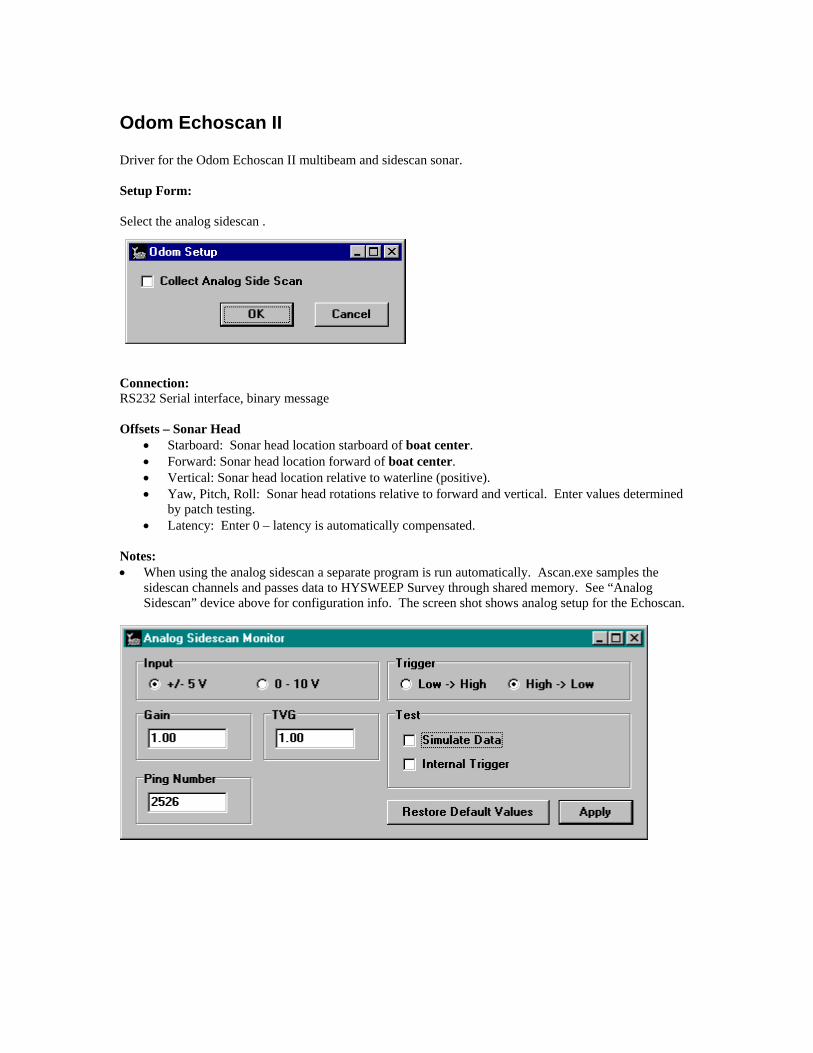
Odom Echoscan II Driver for the Odom Echoscan II multibeam and sidescan sonar. Setup Form: Select the analog sidescan .
Connection: RS232 Serial interface, binary message Offsets – Sonar Head
• Starboard: Sonar head location starboard of boat center. • Forward: Sonar head location forward of boat center. • Vertical: Sonar head location relative to waterline (positive). • Yaw, Pitch, Roll: Sonar head rotations relative to forward and vertical. Enter values determined
by patch testing. • Latency: Enter 0 – latency is automatically compensated.
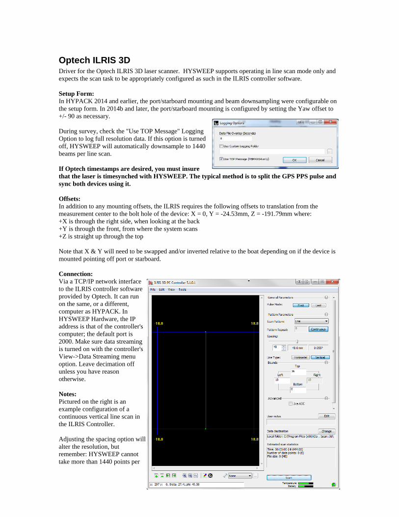
Notes: • When using the analog sidescan a separate program is run automatically. Ascan.exe samples the
sidescan channels and passes data to HYSWEEP Survey through shared memory. See “Analog Sidescan” device above for configuration info. The screen shot shows analog setup for the Echoscan.

Odom ES3 Driver for the Odom ES3 multibeam. See Imagenex Delta-T.

Odom ES3 – Dual Head Driver for the Odom ES3 dual head multibeam. See Imagenex Delta-T – dual head.

Odom MB1 Driver for the Odom MB1 multibeam system. 120 degree system. Setup Form: • Use RTA Interface – Normally checked on. Receive motion and
heading corrections via the Real Time Appliance interface. With this option, all time tagging is done outside HYPACK and HYSWEEP survey.
• Log Snippets – Check this box to log raw data to a *.MB1 file. The MB1 file is used for snippet post processing.
• Max Beams Used (Per Head) – Number of beams logged by HYSWEEP survey. Normally 240, although the MB1 is capable of 512 beams.
Connection: Network interface using UDP datagrams. In testing on the Odom boat, the HYPACK computer IP address was set at 192.168.1.4. • Port – Default is 56002. • Internet address – 127.0.0.1 or address of the MB1 top side unit. Network Test: • UDP Connect – Click to view the unparsed network messages. Offsets: • Sonar Head 1 – Enter location and patch test offsets. Latency should be 0. • MRU Offsets – MRU offsets should be entered when using the RTA interface. • Heading Offset (Yaw) – Enter when using the RTA interface. Setup in HYPACK Hardware When using the RTA interface, setup the GPS.DLL driver as shown.

Odom MB1 – Dual Head Driver for the Odom dual head MB1. With 30 degree rotation of each head, the system provides + / - 180 degree coverage with 30 degree overlap at nadir. Setup Form: • Use RTA Interface – Normally checked on. Receive motion
and heading corrections via the Real Time Appliance interface. With this option, all time tagging is done outside HYPACK and HYSWEEP survey.
• Log Snippets – Snippets are not supported by the dual head driver.
• Max Beams Used (Per Head) – Number of beams logged by HYSWEEP survey. Normally 240 beams per head = 480 beams total.
Connection: Network interface using UDP datagrams. In testing on the Teledyne boat “Bottom Line”, the HYPACK computer IP address was set at 192.168.1.4. • Port – Default is 56002. • Internet address – 127.0.0.1 or address of the master MB1 top
side unit. Network Test: • UDP Connect – Click to view the unparsed network messages. Offsets: • Sonar Heads 1 and 2 – Enter location and patch test offsets. Latency should be 0. • MRU Offsets – MRU offsets should be entered when using the RTA interface. • Heading Offset (Yaw) – Enter when using the RTA interface. Setup in HYPACK Hardware See Odom MB1 setup. Notes: • The driver will not collect data unless both heads are pinging. • The driver works properly in both MB1 ping modes; Alternate and Simultaneous. • Ping rate (each head) should be limited to 20 times per second. This limitation allows the driver to
accommodate Windows networking delays.

Odom Miniscan Driver for the Odom Miniscan multiple transducer system. Setup Form: No specific setup for this driver. Connection: RS232 Serial interface. An example message is shown below: $ F 45.10 45.20 45.00 43.40 43.50 43.60 44.70 45.80 Offsets – Transducers 1 through 8:
• Starboard: Transducer position starboard of boat center. • Forward: Transducer position forward of boat center. • Vertical: Transducer draft (positive). • Yaw, Pitch, Roll: All zeros. • Latency: Enter the latency time (positive, seconds) appropriate for each transducer.
Notes:
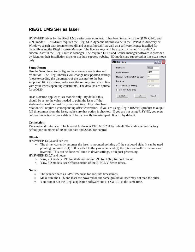
Optech ILRIS 3D Driver for the Optech ILRIS 3D laser scanner. HYSWEEP supports operating in line scan mode only and expects the scan task to be appropriately configured as such in the ILRIS controller software. Setup Form: In HYPACK 2014 and earlier, the port/starboard mounting and beam downsampling were configurable on the setup form. In 2014b and later, the port/starboard mounting is configured by setting the Yaw offset to +/- 90 as necessary. During survey, check the "Use TOP Message" Logging Option to log full resolution data. If this option is turned off, HYSWEEP will automatically downsample to 1440 beams per line scan. If Optech timestamps are desired, you must insure that the laser is timesynched with HYSWEEP. The typical method is to split the GPS PPS pulse and sync both devices using it. Offsets: In addition to any mounting offsets, the ILRIS requires the following offsets to translation from the measurement center to the bolt hole of the device: X = 0, Y = -24.53mm, Z = -191.79mm where: +X is through the right side, when looking at the back +Y is through the front, from where the system scans +Z is straight up through the top Note that X & Y will need to be swapped and/or inverted relative to the boat depending on if the device is mounted pointing off port or starboard. Connection: Via a TCP/IP network interface to the ILRIS controller software provided by Optech. It can run on the same, or a different, computer as HYPACK. In HYSWEEP Hardware, the IP address is that of the controller's computer; the default port is 2000. Make sure data streaming is turned on with the controller's View->Data Streaming menu option. Leave decimation off unless you have reason otherwise. Notes: Pictured on the right is an example configuration of a continuous vertical line scan in the ILRIS Controller. Adjusting the spacing option will alter the resolution, but remember: HYSWEEP cannot take more than 1440 points per

line. Resolution that is too high will cause the scanner to return fewer lines per second and all the extra points will be thrown away anyway. For optimum data density, adjust the spacing to return close to the same number of beams set in HYSWEEP Hardware. What you "sacrifice" in resolution you make up for in more pings per second., which could actually give you more points per second. 2014 and Earlier Setup Form: The setup form provides several options: 1. The number of beams per line. Input will be decimated to fit and is subject to the HYSWEEP limit of 1440 beams per ping. 2. Specify if the laser is mounted to scan off the port or starboard side of the boat. 3. Optech can optionally provide timestamps. 'Use PC Time' will ignore their timestamps and use Veritime instead. If not provided, the driver defaults to Veritime. If Optech timestamps are desired, you must insure that the laser is timesynched with HYSWEEP. The typical method is to split the GPS PPS pulse and sync both devices using it.

Picotech PicoMBES The Picotech PicoMBES is a range/angle echosounder with 40° and 120° models. Connection: UDP network connection. The sonar expects the HYPACK computer to have address 10.0.100.70 and to receive data on port 13000. The MBES is 10.0.100.120 and sends data from port 9000. The MBES port and address is what should be entered in HYPACK HARDWARE. Setup: No setup form. Notes:
• As of May 2016 the IP addresses are not configurable on the Picotech side. This may change in the future
• GPS & PPS should be wired into the PicoMBES cabling to insure valid timetagging Controller:

PingDSP 3DSS-DX Driver for the PingDSP interferometer. It is a passive TCP/IP network driver which reads bathymetry, side scan, motion, and heading data. Setup Form: Configure the type of message being sent to HYPACK by the PingDSP controller here. Connection: Via a TCP/IP network interface to the controller software provided by PingDSP. Enter the IP address of the controller software on the Connect tab. The port is locked to the manufacturer default: 23848. See Appendix C for details on real-time processing of interferometry data in HYSWEEP.

R2Sonic Dual Head HYSWEEP driver for R2Sonic sonar in dual head configuration. The driver merges data from two heads for logging and processing. Setup Form: Data Format: Select R2Sonic format. Local IP Address: We pass this to the sonar processor so it knows where to send data. This is the IP address of the computer running HYPACK / HYSWEEP. Log Snippet Data: Ignored – dual head driver does not support snippets. TruePix Data: Enables HYSWEEP Survey logging of TruePix data. Data is logged to *.R2S files. These files may become large, so don’t select this option unless you wish to post-process the TruePix imagery. Log Water Column Data: Not supported by dual head driver. Connection: Network connection using UDP datagrams. Settings for the first sonar unit (head 1) are shown in the Connect tab of HYSWEEP Hardware. Default port (4000) and IP address (10.0.0.86) should be correct. Settings for the second sonar unit (head 2) are fixed in HYSWEEP; port = 5000, IP address = 10.0.1.86. Network Test: Enter Port and IP Address to test head 1 or 2. Offsets: Enter head 1 and 2 location offsets relative to boat reference. Enter head 1 and 2 rotation offsets from patch testing. Notes: • The driver will not collect data unless both heads are pinging. • The driver works properly in both R2Sonic ping modes; Alternate and Simultaneous. • All R2Sonic models are supported (2024, 2022, etc.) and may even be mixed. For example, head 1 is
2024 sonar, head 2 is 2022. • Ping rate (each head) should be limited to 20 times per second. This limitation allows the driver to
accommodate Windows networking delays.

R2Sonic SONIC 2024 HYSWEEP driver for the R2Sonic SONIC 2024 multibeam sonar. Also works with the 2022 model. Setup Form: Data Format: Select R2Sonic mode. Local IP Address: We pass this to the sonar processor so it knows where to send data. This is the IP address of the computer running HYPACK / HYSWEEP. Log Snippet/TruePix Data: Enables HYSWEEP Survey logging of snippet or TruePix data. Data is logged to *.R2S files. These files may become very large, so don’t select this option unless you wish to post-process the snippets/truepix imagery. Log Water Column Data: Enables water column logging starting with HYPACK 2015. Data is logged to *_WC.R2S files. These files will become ridiculously large. Connection: Network connection using UDP datagrams. The default port is 4000. Default IP address of the sonar unit is 10.0.0.86. Offsets:
• Starboard: Sonar head location starboard of boat center. • Forward: Sonar head location forward of boat center. • Vertical: Sonar head location relative to waterline
(positive). • Yaw, Pitch, Roll: Sonar head rotations relative to forward
and vertical. Enter values determined by patch testing. • Latency: Enter 0 – latency is automatically compensated.
Notes: • Example setup of the network adapter is shown at right. The
subnet mask is not typical. TruePix Configuration: HYSWEEP 13.0.6 and earlier (see screenshot at the right):
#1 only. – logging only, no display (for slow hardware only) #1 & #2. – logging, display in Intensity Window (recommended) #1, #2, & #3 – logging, display in Intensity and Sidescan Window
(not recommended; not for large ranges, bigger HSX files) HYSWEEP 13.0.7 and newer: simply check “Log TruePix Data” (see above). In the R2Sonic software: go to Settings->Sonar Settings... Check either “TruePix Enable” or “Snippets Enable.”

R2Sonic SONIC 2024 (Seabat 81P compatible mode) HYSWEEP driver for the R2Sonic SONIC 2024 multibeam sonar. Also works with the 2022 sonar. The compatibility mode allows all post processing tools that work with 81P systems to work with the R2Sonic. However, many of the advanced sonar features (sector rotation for example) are not available in the compatible mode. Setup Form: Data Format: Select Seabat 81P Compatible to run in compatibility mode. Log Sidescan Data: Enables HYSWEEP Survey display and logging of sidescan data. Data is logged to *.HSX file along alongside the multibeam data. Sidescan data may be useful to the poor fellow who does the editing, and is therefore recommended. Log Snippet Data: Enables HYSWEEP Survey display and logging of snippet data. Data is logged to *.81X files. These files may become very large, so do not select this option unless you wish to post-process the snippets. Connection: Network connection using UDP datagrams. The default port is 4000. Default IP address of the data collection computer is 10.0.0.86. Offsets:
• Starboard: Sonar head location starboard of boat center. • Forward: Sonar head location forward of boat center. • Vertical: Sonar head location relative to waterline (positive). • Yaw, Pitch, Roll: Sonar head rotations relative to forward and vertical. Enter values determined
by patch testing. • Latency: Enter 0 – latency is automatically compensated.
Notes: • Was it mentioned that the 81X files are huge?

Renishaw SLM laser HYSWEEP driver for the Renishaw SLM laser scanner. The device offers a 360 degree swath and up to 0.01 degree resolution. It was formerly known as the MDL Dynascan. Setup Form: None. Use the runtime controller to configure the resolution and rotation speed. Connection: Via a network interface. The Internet Address is 192.168.0.10 and port 30 by default. Notes: The driver requests the “X1” data format from the SLM which includes PPS timestamped data, if the device firmware does not support this, arrival time is used to timetag points. The timetag of the first point is used as the ping time. Subsequent points are assigned a delay relative to ping time.
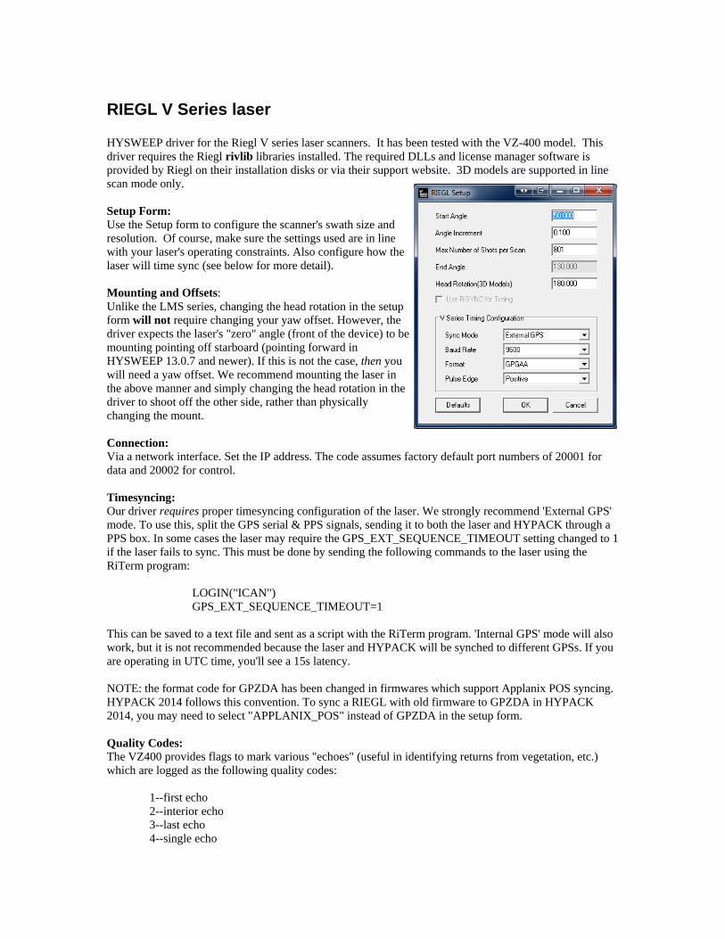
RIEGL LMS Series laser HYSWEEP driver for the Riegl LMS series laser scanners. It has been tested with the Q120, Q240, and Z390 models. This driver requires the Riegl SDK dynamic libraries to be in the HYPACK directory or Windows search path (scannermod.dll and scancnfmod.dll) as well as a software license installed for riscanlib using the Riegl License Manager. The license keys will be explicitly named “riscanlib” or “riscanlib3d” in the Riegl License Manager. The required DLLs and license manager software is provided by Riegl on their installation disks or via their support website. 3D models are supported in line scan mode only. Setup Form: Use the Setup form to configure the scanner's swath size and resolution. The Riegl libraries will change unsupported settings (those exceeding the parameters of the scanner) to the best supported fit. Of course, make sure the settings used are in line with your laser's operating constraints. The defaults are optimal for a Q120. Head Rotation applies to 3D models only. By default this should be set to the value needed to point the laser off the starboard side of the boat for your mounting. Any other head rotation will require a corresponding offset correction. If you are using Riegl's RiSYNC product to output full timestamps from the laser, make sure that option is checked. If you are not using RiSYNC, you must not use this option or your data will be incorrectly timestamped. It is off by default. Connection: Via a network interface. The Internet Address is 192.168.0.234 by default. The code assumes factory default port numbers of 20001 for data and 20002 for control. Offsets: HYSWEEP 13.0.6 and earlier:
The driver currently assumes the laser is mounted pointing off the starboard side. It can be used pointing port-side if (1) 180 is added to the yaw offset and (2) the pitch and roll corrections are inverted. This can be done real-time in driver settings, or in post-processing.
HYSWEEP 13.0.7 and newer: Yaw, 2D models: +90 for starboard mount. -90 (or +260) for port mount. Yaw, 3D models: see Offsets section of the RIEGL V Series notes.
Notes:
• The scanner needs a GPS PPS pulse for accurate timestamps. • Make sure the GPS and laser are powered on the same ground or laser may not read the pulse. • You cannot run the Riegl acquisition software and HYSWEEP at the same time.
RIEGL V Series laser HYSWEEP driver for the Riegl V series laser scanners. It has been tested with the VZ-400 model. This driver requires the Riegl rivlib libraries installed. The required DLLs and license manager software is provided by Riegl on their installation disks or via their support website. 3D models are supported in line scan mode only. Setup Form: Use the Setup form to configure the scanner's swath size and resolution. Of course, make sure the settings used are in line with your laser's operating constraints. Also configure how the laser will time sync (see below for more detail). Mounting and Offsets: Unlike the LMS series, changing the head rotation in the setup form will not require changing your yaw offset. However, the driver expects the laser's "zero" angle (front of the device) to be mounting pointing off starboard (pointing forward in HYSWEEP 13.0.7 and newer). If this is not the case, then you will need a yaw offset. We recommend mounting the laser in the above manner and simply changing the head rotation in the driver to shoot off the other side, rather than physically changing the mount. Connection: Via a network interface. Set the IP address. The code assumes factory default port numbers of 20001 for data and 20002 for control. Timesyncing: Our driver requires proper timesyncing configuration of the laser. We strongly recommend 'External GPS' mode. To use this, split the GPS serial & PPS signals, sending it to both the laser and HYPACK through a PPS box. In some cases the laser may require the GPS_EXT_SEQUENCE_TIMEOUT setting changed to 1 if the laser fails to sync. This must be done by sending the following commands to the laser using the RiTerm program:
LOGIN("ICAN") GPS_EXT_SEQUENCE_TIMEOUT=1
This can be saved to a text file and sent as a script with the RiTerm program. 'Internal GPS' mode will also work, but it is not recommended because the laser and HYPACK will be synched to different GPSs. If you are operating in UTC time, you'll see a 15s latency. NOTE: the format code for GPZDA has been changed in firmwares which support Applanix POS syncing. HYPACK 2014 follows this convention. To sync a RIEGL with old firmware to GPZDA in HYPACK 2014, you may need to select "APPLANIX_POS" instead of GPZDA in the setup form. Quality Codes: The VZ400 provides flags to mark various "echoes" (useful in identifying returns from vegetation, etc.) which are logged as the following quality codes:
1--first echo 2--interior echo 3--last echo 4--single echo


Reson Dual 7125 HYSWEEP driver for the Seabat 7125 in dual head configuration. Setup Form: Side Scan Option: Check this to enable side scan data. Use Snippets: Not support in dual head driver.. Log Seabat Datagrams: Use this to log raw network datagrams to *.7K files. Datagram Version 1: Dual head driver uses version 1 only. Slave IP Address: Set the IP Address of the slave 7125. Send Start and Stop Logging Commands to the Seabat: Causes the Seabat to log data files with the same name as HYPACK files. Connection: Use the Connect tab to enter the IP Address of the master 7125. Network port will always be 7000. Offsets - For each head, enter the following:
• Starboard: Sonar head location starboard of boat center.
• Forward: Sonar head location forward of boat center.
• Vertical: Sonar head location relative to waterline (positive).
• Yaw, Pitch, Roll: Sonar head rotations relative to forward and vertical. Enter values determined by patch testing.
• Latency: Enter 0 – latency is automatically compensated. Notes:
• Supports Seabat version 1 datagrams. Version 2 is not supported. • HYSWEEP Sonar head 1 is the master 7125 and must be mounted on the port side with the
connector to the left (as per Reson documentation). HYWEEP sonar head 2 is the slave 7125 mounted facing starboard. Again, with the connector on the left.
• In the Tetra Tech installation, 7125 master IP address = 192.168.3.50. Slave IP Address = 192.168.3.49.
• Side scan data is collected from both heads. At this time, only head 1 is shown in the HYSWEEP Survey real time displays. Snippet data is not collected by the dual head driver.

Reson Dual 8101 (NY) HYSWEEP driver for the dual Seabat 8101 system installed on USACE S/V Moritz. Setup Form:
The only thing that need be entered is the COM Port for Time Sync. This is important for proper time tagging of the multibeam data. Connection: Multibeam and Sidescan data are via network interface. Network port is hard wired to 1029 (head 1) and 1038 (head 2). Offsets: For the port and starboard heads, enter:
• Starboard, Forward, Vertical offsets relative to the boat origin / water line. • Yaw, Pitch, Roll: Sonar head rotations relative to forward and vertical. Enter values determined
by patch testing. • Latency: Enter 0 – latency is automatically compensated.
Seabat Setup The IP address of the HYPACK PC must match the remote address entered in the port and starboard Seabat controllers. Notes:

Reson Seabat 7101, 7125, 7150, 7160, 8125H, T20-P HYSWEEP driver for the Reson Seabat 7k multibeam sonar systems. Uses a network interface to provide multibeam soundings, side scan, snippet and water column data. Setup Form:
Side Scan Option: Check this to enable side scan data. Use Snippets: Check this to use Seabat snippet data. See Notes. Log Seabat Datagrams: Use this to log raw network datagrams to *.7K files. This is done automatically if snippets are enabled. Datagram Version 1: Original data format used by Reson. You can use this until the Seabat is updated to a version that doesn’t support it. Datagram Version 2: Updated format available in 2010. This is an improvement over version 1 in that snippet data is compressed and beam data is completely uncorrected. Snippet Samples per Beam (Version 1): All beams contain the same number of snippet samples. 1103 command to Seabat.
Auto: N/A. Min: N/A. Max: Selects snippet samples per beam.
Snippet Samples per Beam (Version 2): Option for variable samples per beam. 1118 command to Seabat.

Auto: Snippet samples per beam chosen for 3 dB overlap. Results in much less data than constant samples per beam.
• Min: Minimum Window Size. Include at least this number of samples around bottom detection. • Max: Maximum Window Size. Include at most this number of samples.
Transmitter Offsets (from Receiver): Accounts for the transmitter offsets of dual frequency 7125 systems. (The 200 and 400 kHz transmitters are separate from each other and the receiver.) In HYPACK 2012A and later, these values are read from the Seabat controller. Send Start and Stop Logging Commands to the Seabat: Causes the Seabat to log data files with the same name as HYPACK files. Use RESON Remote IO: Reads time tagged motion and heading data from the selected network port. Log Water Column: Enables water column logging starting with HYPACK 2015. Data is logged to *_WC.7K files. These files will become ridiculously large. Connection: Multibeam and side scan data are via a network interface. Set port number to 7000 and use the Internet Address of the 7125 controller. Offsets:
• Starboard: Sonar head location starboard of boat center. • Forward: Sonar head location forward of boat center. • Vertical: Sonar head location relative to waterline (positive). • Yaw, Pitch, Roll: Sonar head rotations relative to forward and vertical. Enter values determined
by patch testing. • Latency: Enter 0 – latency is automatically compensated.
Notes: • Although it is possible to switch the 7125 between equal beam spacing (256 beams) and equal
footprint (512 beams), you should decide which is better for you and stick with that for the entire survey. This will avoid potential problems in HYSWEEP post-processing.
• The 7125 controller must be powered on before starting HYSWEEP survey. • Snippets – If snippets are enabled in the driver and turned on in the Seabat, a couple of things happen.
1. The Intensity Waterfall will show snippets instead of intensity. 2. Large files containing raw Seabat datagrams (*.7K) are logged for snippet post processing. 3. You must be careful with snippets using the Version 1 datagrams. Say you are pinging 40 times
per second in shallow water, using 512 beams at equal spacing and saving 300 snippet samples per beam (300 is the Seabat default). 2 bytes per sample. You will then try to collect 40 * 512 * 300 * 2 = 12,288,000 bytes per second = 0.75 Gigabytes / minute. NO! The network will likely choke and even if it doesn’t, this is too much for the GSF files used in snippet post processing. Cut down the number of samples to 50 or less if you ping at high rates in shallow water. 25 pings per second, 25 snippet samples per beam is reasonable.
4. Snippet data is optimized (much less data!) using the version 2 datagrams.

Reson Seabat 8101 HYSWEEP driver for Reson Seabat 8101 Multibeam sonar / sidescan. Setup Form:
Enter the number of beams you are using (101 for 150 degree swath, 141 for 210 degree swath). If the Seabat is set up for sidescan output, check “Side Scan Option”. The default port = 1028 should not need to be changed. Connection: Multbeam data is via an RS232 interface (binary). Sidescan uses the network. Offsets:
• Starboard: Sonar head location starboard of boat center. • Forward: Sonar head location forward of boat center. • Vertical: Sonar head location relative to waterline (positive). • Yaw, Pitch, Roll: Sonar head rotations relative to forward and vertical. Enter values determined
by patch testing. • Latency: Enter 0 – latency is automatically compensated.
Seabat Setup The Remote IP address must match the address of the HYPACK/HYSWEEP computer. If you don’t know how to set up IP addresses, consult the office network guru. Notes:

Reson Seabat 81xx (Network) HYSWEEP driver for Reson Seabat 8124, 8125 and some 8101 multibeam sonar models. This driver is appropriate when using the network interface for data transfer. Provides multibeam soundings and sidescan data. Setup Form: Side Scan Option: Check this to enable side scan data. Use Snippets: Check this to use Seabat snippet data. See Notes. Log Seabat Datagrams: Use this to log raw network datagrams to *.81X files. COM Port for Time Synch: When using this driver, it is necessary to time synchronize the Seabat sonar unit with the HYPACK / HYSWEEP computer. That is done through the COM port specified here. Connection: Multibeam and side scan data are via a network interface. Set port number to match the Seabat controller (1028 by default) and use the default Internet Address (127.0.0.1). Offsets:
• Starboard: Sonar head location starboard of boat center. • Forward: Sonar head location forward of boat center. • Vertical: Sonar head location relative to waterline (positive). • Yaw, Pitch, Roll: Sonar head rotations relative to forward and vertical. Enter values determined
by patch testing. • Latency: Enter 0 – latency is automatically compensated.
Seabat Setup Ethernet Port should be 1028 and the Remote IP address must match the address of the HYPACK / HYSWEEP computer. Notes: • Intensity – Intensity (average backscatter) data is collected and display when the RI-Theta message is
sent by the Seabat. I=Intensity. • Snippets – If snippets are enabled in the driver and turned on in the Seabat, a couple of things happen.
1. The Intensity Waterfall will show snippets instead of intensity. 2. Large files containing raw Seabat datagrams (*.81X) are logged for snippet post
processing.

Reson Seabat 81xx (Serial) HYSWEEP driver for Reson Seabat 8124, 8125 and some 8101 multibeam sonar models. This driver is appropriate when using the serial (COM port) interface for data transfer. Connection: Multbeam data is via an RS232 interface (binary). Offsets:
• Starboard: Sonar head location starboard of boat center. • Forward: Sonar head location forward of boat center. • Vertical: Sonar head location relative to waterline (positive). • Yaw, Pitch, Roll: Sonar head rotations relative to forward and vertical. Enter values determined
by patch testing. • Latency: Enter 0 – latency is automatically compensated.
Notes:

Reson Seabat 9001 / 9003 HYSWEEP driver for Reson Seabat 9001 / 9003 Multibeam sonar. Connection: RS232 Serial interface, binary message. HYSWEEP survey accepts both the R-Theta (Range - Angle) and RI-Theta (Range, Intensity – Angle) messages from the 9001, R-Theta only from the 9003. Offsets:
• Starboard: Sonar head location starboard of boat center. • Forward: Sonar head location forward of boat center. • Vertical: Sonar head location relative to waterline (positive). • Yaw, Pitch, Roll: Sonar head rotations relative to forward and vertical. Enter values determined
by patch testing. • Latency: Enter 0 – latency is automatically compensated.
Notes: • The 9001 has 60 beams at 1.5 degree spacing for a swath of 90 degrees. • The 9003 has 40 beams at 3.0 degree spacing for a swath of 120 degrees.
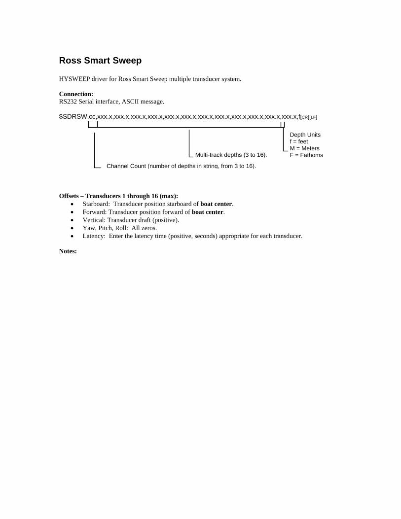
Ross Smart Sweep HYSWEEP driver for Ross Smart Sweep multiple transducer system. Connection: RS232 Serial interface, ASCII message. $SDRSW,cc,xxx.x,xxx.x,xxx.x,xxx.x,xxx.x,xxx.x,xxx.x,xxx.x,xxx.x,xxx.x,xxx.x,xxx.x,f[CR][LF]
Offsets – Transducers 1 through 16 (max):
• Starboard: Transducer position starboard of boat center. • Forward: Transducer position forward of boat center. • Vertical: Transducer draft (positive). • Yaw, Pitch, Roll: All zeros. • Latency: Enter the latency time (positive, seconds) appropriate for each transducer.
Notes:
Depth Units f = feet M = Meters F = Fathoms Multi-track depths (3 to 16).
Channel Count (number of depths in string, from 3 to 16).

Seabeam 1000 Series HYSWEEP driver for the Seabeam 1000 series of multibeam sonar systems. Supported models are: • SB1185 - 0-300 m depth, 180 khz • SB1180 - 0-600 m depth, 180 khz • SB1055 - 0-1500 m depth, 50 khz • SB1050 - 0-3500 m depth, 50 khz • SB1055D - SB1180 + SB1055 (dual frequency) • SB1050D - SB1180 + SB1050 (dual frequency) All provide roll corrected multibeam soundings along with HPR data. A Seabeam program, Hydrostar Online, runs in the same PC as HYPACK/HYSWEEP. Hydrostar controls the sonar and provides the sounding and MRU data to HYSWEEP survey. Setup Form:
Record XSE Records: Check this to save raw messages from the Hydrostar program. Useful only for diagnostics and filling up a disk drive. Record Beam Intensity: Check this to save beam intensity values for use in multibeam editing. Intensity is displayed in the HYSWEEP multibeam waterfall display. Connection: Multbeam data is via a network interface internal to the PC (no wires!). Use Internet Address = 127.0.0.1 and Port = 3400. Offsets - MRU:
• Starboard: MRU location starboard of boat center. • Forward: MRU location forward of boat center. • Vertical: MRU location relative to waterline (positive below). • Yaw: Enter 0. • Pitch, Roll: Enter 0 (MRU pitch/roll offsets are typically zeroed within the MRU itself). • Latency: Enter 0.
Offsets – Sonar Heads 1 and 2:
• Starboard: Sonar head locations starboard of boat center. • Forward: Sonar head locations forward of boat center. • Vertical: Sonar head locations relative to waterline (positive). • Yaw, Pitch: Sonar head rotations. Enter values determined by patch testing in HYSWEEP
hardware. • Roll: Sonar head rotations from patch test. Enter values under Hydrostar ship parameters, NOT
HYSWEEP (0 in HYSWEEP). • Latency: Enter 0.

Notes: • Dual Head Systems: Separate and different offsets exist for each set of transducers. The surveyor
must remember to enter the offsets appropriate for the transducers used in the survey. • Quality Coding: The Hydrostar online program encodes sounding quality; 1 = high quality to 8 =
low quality to 9 = bad. HYSWEEP requires the reverse ordering so HYSWEEP quality = 9 – Hydrostar quality.
Sounding Quality Hydrostar Code HYSWEEP Code Excellent 1 8 Poor 8 1 No Good 9 0
• When the number of beams is changed during survey it effects the editing process. Enter Fixed Number of Beams = 126 in Mbmax Read Parameters, Advanced tab (below). 126 is the maximum number of beams available in the system.

Seabeam 2100 HYSWEEP driver for Seabeam 2100 multibeam sonar. The driver provides heave, pitch, roll and sound velocity corrected soundings. Heading information is included in the 2100 datagram. Connection: TCP/IP connection. Use Internet Address = 127.0.0.1 and Port = 5209 in HYSWEEP Hardware. (The PC must have IP address matching the 2100 “Sea Logger” address – 198.114.228.32 in one installation.) Offsets - Gyro:
• Starboard, Forward and Vertical: Enter 0. • Yaw, Pitch and Roll: Enter 0. • Latency: Enter 0.
Offsets – Sonar Head:
• Starboard and Forward: Enter transducer position relative to boat reference. • Vertical: Enter 0 – Draft is entered in 2100 Operators Station. • Yaw: Enter the calibration offset. • Pitch and Roll: Enter 0 – These are entered in 2100 Operators Station.. • Latency: Enter 0.
Notes:
• Because sounding corrections are done before data is sent to HYSWEEP, data can not be re-corrected later.
• As with all network interfaces, both the HYPACK PC and the remote computer (2100 operators station) must be time synchronized to GPS time using the $GPZDA message.
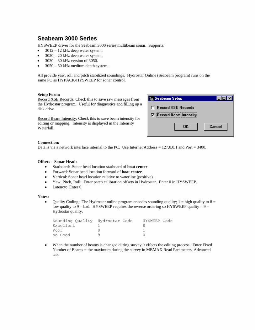
Seabeam 3000 Series HYSWEEP driver for the Seabeam 3000 series multibeam sonar. Supports: • 3012 – 12 kHz deep water system. • 3020 – 20 kHz deep water system. • 3030 – 30 kHz version of 3050. • 3050 – 50 kHz medium depth system. All provide yaw, roll and pitch stabilized soundings. Hydrostar Online (Seabeam program) runs on the same PC as HYPACK/HYSWEEP for sonar control. Setup Form: Record XSE Records: Check this to save raw messages from the Hydrostar program. Useful for diagnostics and filling up a disk drive. Record Beam Intensity: Check this to save beam intensity for editing or mapping. Intensity is displayed in the Intensity Waterfall. Connection: Data is via a network interface internal to the PC. Use Internet Address = 127.0.0.1 and Port = 3400. Offsets – Sonar Head:
• Starboard: Sonar head location starboard of boat center. • Forward: Sonar head location forward of boat center. • Vertical: Sonar head location relative to waterline (positive). • Yaw, Pitch, Roll: Enter patch calibration offsets in Hydrostar. Enter 0 in HYSWEEP. • Latency: Enter 0.
Notes:
• Quality Coding: The Hydrostar online program encodes sounding quality; 1 = high quality to 8 = low quality to 9 = bad. HYSWEEP requires the reverse ordering so HYSWEEP quality = 9 – Hydrostar quality.
Sounding Quality Hydrostar Code HYSWEEP Code Excellent 1 8 Poor 8 1 No Good 9 0
• When the number of beams is changed during survey it effects the editing process. Enter Fixed Number of Beams = the maximum during the survey in MBMAX Read Parameters, Advanced tab.

Simrad EM3000 HYSWEEP driver for the Simrad EM3000 multibeam sonar. Provides pitch and roll corrected multibeam soundings along with HPR and heading data. Connection: All data is via a network interface. In HYSWEEP hardware, use default Internet Address (127.0.0.1) and Port number to match that set in the EM3000 (2060 in one installation). In windows Network properties, the HYPACK PC must be set to the IP address used by the EM3000. Settings at the Port of Valencia are shown below. Offsets - MRU:
• Starboard: MRU location starboard of boat center.
• Forward: MRU location forward of boat center.
• Vertical: MRU location relative to waterline (positive below).
• Yaw, Pitch, Roll: Enter 0 (see notes). • Latency: Enter 0.
Offsets - Gyro:
• Starboard, Forward, Vertical: Enter 0. • Yaw: Typically 0. • Pitch, Roll, Latency: Enter 0.
Offsets – Sonar Heads 1 and 2:
• Starboard: Sonar head locations starboard of boat center. • Forward: Sonar head locations forward of boat center. • Vertical: Sonar head locations relative to waterline (positive). • Yaw, Pitch, Roll: Sonar head rotations - enter values determined by patch testing (see notes) • Latency: Enter 0.
Notes: • HYSWEEP survey requires 3 datagrams from the EM3000: Attitude (A=41), Depth (D=44) and Raw
Range and Beam Angles (F=46). (A) gives heave, pitch, roll and heading, (D) is only used for the sonar sampling rate and (F) is the raw sonar data.
• EM3000 calibration offsets are entered under MRU pitch/roll/heading. DO NOT enter these values in HYSWEEP hardware as we subtract MRU pitch/roll offsets and Simrad adds them. Instead, add them to EM3000 sonar installation offsets and enter in HYSWEEP hardware under sonar yaw/pitch/roll. It is better to ignore the Simrad angles and do the calibrations in HYSWEEP patch test.
• The EM3000 comes in single and dual head models. Enter offsets accordingly. • Both the HYPACK/HYSWEEP computer and the EM3000 must be time synchronized to UTC time
($GPZDA message) for data times to match up.
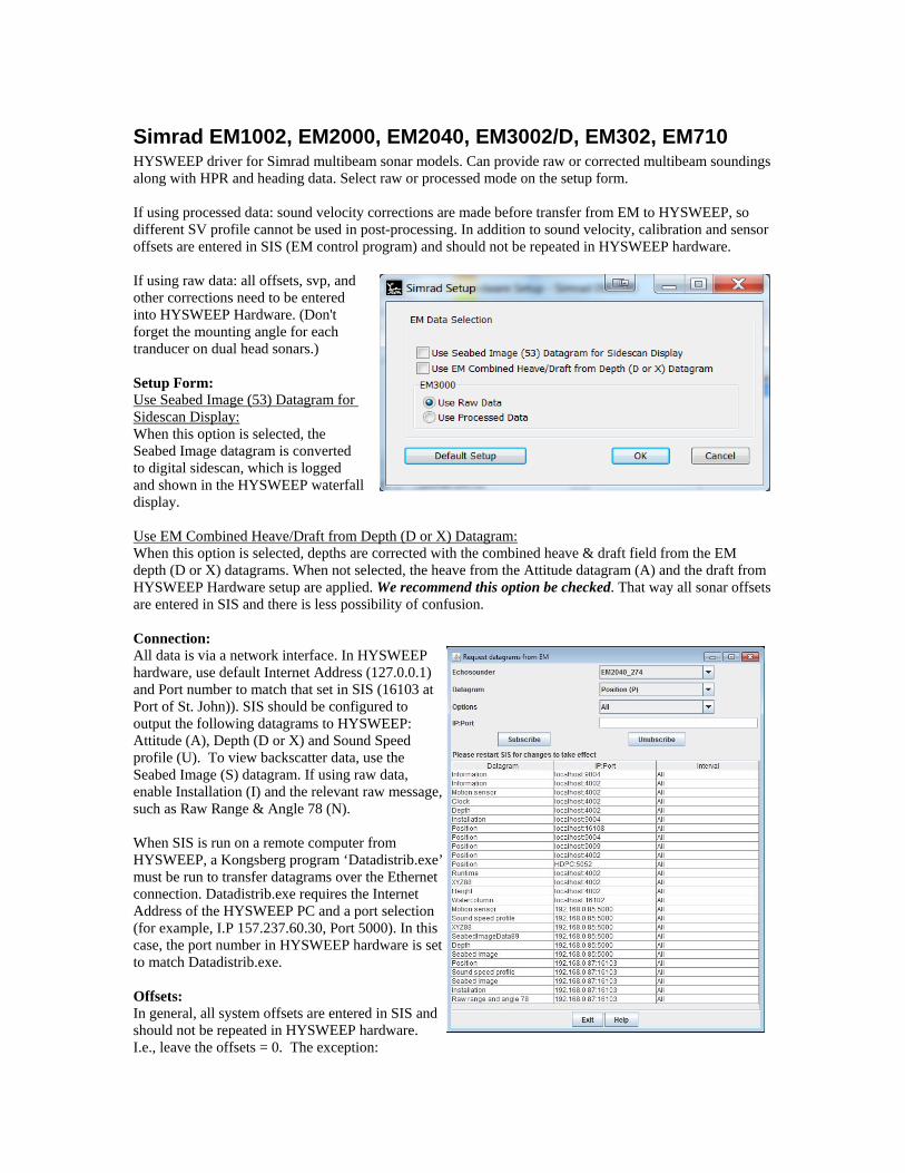
Simrad EM1002, EM2000, EM2040, EM3002/D, EM302, EM710 HYSWEEP driver for Simrad multibeam sonar models. Can provide raw or corrected multibeam soundings along with HPR and heading data. Select raw or processed mode on the setup form. If using processed data: sound velocity corrections are made before transfer from EM to HYSWEEP, so different SV profile cannot be used in post-processing. In addition to sound velocity, calibration and sensor offsets are entered in SIS (EM control program) and should not be repeated in HYSWEEP hardware. If using raw data: all offsets, svp, and other corrections need to be entered into HYSWEEP Hardware. (Don't forget the mounting angle for each tranducer on dual head sonars.) Setup Form: Use Seabed Image (53) Datagram for Sidescan Display: When this option is selected, the Seabed Image datagram is converted to digital sidescan, which is logged and shown in the HYSWEEP waterfall display. Use EM Combined Heave/Draft from Depth (D or X) Datagram: When this option is selected, depths are corrected with the combined heave & draft field from the EM depth (D or X) datagrams. When not selected, the heave from the Attitude datagram (A) and the draft from HYSWEEP Hardware setup are applied. We recommend this option be checked. That way all sonar offsets are entered in SIS and there is less possibility of confusion. Connection: All data is via a network interface. In HYSWEEP hardware, use default Internet Address (127.0.0.1) and Port number to match that set in SIS (16103 at Port of St. John)). SIS should be configured to output the following datagrams to HYSWEEP: Attitude (A), Depth (D or X) and Sound Speed profile (U). To view backscatter data, use the Seabed Image (S) datagram. If using raw data, enable Installation (I) and the relevant raw message, such as Raw Range & Angle 78 (N). When SIS is run on a remote computer from HYSWEEP, a Kongsberg program ‘Datadistrib.exe’ must be run to transfer datagrams over the Ethernet connection. Datadistrib.exe requires the Internet Address of the HYSWEEP PC and a port selection (for example, I.P 157.237.60.30, Port 5000). In this case, the port number in HYSWEEP hardware is set to match Datadistrib.exe. Offsets: In general, all system offsets are entered in SIS and should not be repeated in HYSWEEP hardware. I.e., leave the offsets = 0. The exception:

• When “Use EM Combined Heave/Draft from Depth Datagram” is not selected. In that case, the draft of the sonar head is entered as a vertical offset.
Notes: • Both the HYPACK/HYSWEEP computer and the EM system must be time synchronized to UTC time
($GPZDA message or 1PPS) for data times to match up. • Repeat: You can not apply a sound velocity profile in post processing. • When viewing Seabed Image in HYSWEEP under the Sidescan Waterfall display, the range must be
set manually. Use Sidescan Controls, Display tab to enter range.

Simrad ME70 HYSWEEP driver for the Simrad ME70 sonar. Connection: A network (UDP) interface. The driver communicates with the ME70 terminal software. In HARDWARE, set the IP Address in the driver setup to the address of the terminal computer. The port field is not used. The ME70 has a complicated initialization process. On startup, the driver sends an "RSI" command on port 37655 to request a command connection. The driver is then assigned a command port by the ME70. A second port for data is then opened on port 1502. Beamforming is handled in the driver. The control form allows you to toggle multi-detect and detection gates. Offsets:
• Starboard: Sonar head locations starboard of boat center. • Forward: Sonar head locations forward of boat center. • Vertical: Sonar head locations relative to waterline
(positive). • Yaw, Pitch, Roll: Sonar head rotations - enter values
determined by patch testing. • Latency: Enter 0.
Notes:

Simrad SM2000 HYSWEEP driver for the Simrad SM2000 multibeam sonar. Connection: RS232 Serial interface, binary message. Offsets:
• Starboard: Sonar head locations starboard of boat center. • Forward: Sonar head locations forward of boat center. • Vertical: Sonar head locations relative to waterline (positive). • Yaw, Pitch, Roll: Sonar head rotations - enter values determined by patch testing. • Latency: Enter 0.
Notes:

Seatex MRU6 HYSWEEP driver for the Seatex MRU6 motion reference unit. Provides heave, pitch and roll data. Connection: RS232 Serial interface, binary message. Offsets:
• Starboard: MRU location starboard of boat center. • Forward: MRU location forward of boat center. • Vertical: MRU location relative to waterline (positive below). • Yaw: Enter 0. • Pitch, Roll: Enter 0 (MRU pitch/roll offsets are typically zeroed within the MRU itself). • Latency: Enter 0.
Notes: • HYSWEEP uses the COM port to program the MRU6 to send a particular message. If message is not
received by the MRU6, due to starting HYSWEEP survey before the MRU6 or a broken or missing transmit wire (it’s happened), the driver will not work.
• The MRU6 can be set to output a “Sounder” message, which is identical to the TSS 335B message.

SG Brown 1000S Gyro Driver for the SG Brown gyro. Connection: RS232 Serial interface. An example message is shown below: XXXX<cr><lf> ^^^^ ||||- 1/6th (degrees), HUH? |||-- units (degrees) ||--- tens (degrees) |---- hundreds (degrees) Offsets:
• Starboard, Forward, Vertical: Not used – set to 0. • Yaw: Enter the heading correction if any. • Pitch, Roll: Not used – set to 0. • Latency: Enter the gyro latency time if any - positive, seconds.
Notes:
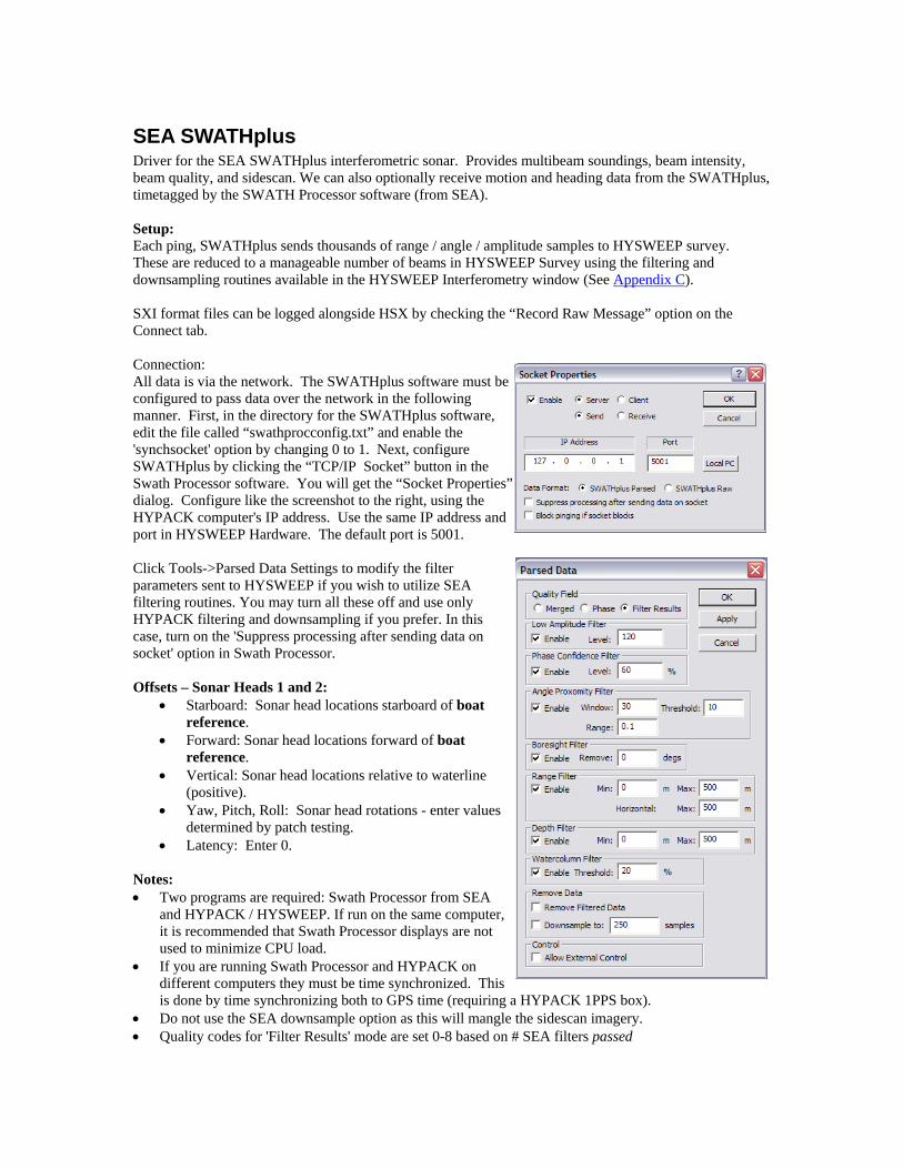
SEA SWATHplus Driver for the SEA SWATHplus interferometric sonar. Provides multibeam soundings, beam intensity, beam quality, and sidescan. We can also optionally receive motion and heading data from the SWATHplus, timetagged by the SWATH Processor software (from SEA). Setup: Each ping, SWATHplus sends thousands of range / angle / amplitude samples to HYSWEEP survey. These are reduced to a manageable number of beams in HYSWEEP Survey using the filtering and downsampling routines available in the HYSWEEP Interferometry window (See Appendix C). SXI format files can be logged alongside HSX by checking the “Record Raw Message” option on the Connect tab. Connection: All data is via the network. The SWATHplus software must be configured to pass data over the network in the following manner. First, in the directory for the SWATHplus software, edit the file called “swathprocconfig.txt” and enable the 'synchsocket' option by changing 0 to 1. Next, configure SWATHplus by clicking the “TCP/IP Socket” button in the Swath Processor software. You will get the “Socket Properties” dialog. Configure like the screenshot to the right, using the HYPACK computer's IP address. Use the same IP address and port in HYSWEEP Hardware. The default port is 5001. Click Tools->Parsed Data Settings to modify the filter parameters sent to HYSWEEP if you wish to utilize SEA filtering routines. You may turn all these off and use only HYPACK filtering and downsampling if you prefer. In this case, turn on the 'Suppress processing after sending data on socket' option in Swath Processor. Offsets – Sonar Heads 1 and 2:
• Starboard: Sonar head locations starboard of boat reference.
• Forward: Sonar head locations forward of boat reference.
• Vertical: Sonar head locations relative to waterline (positive).
• Yaw, Pitch, Roll: Sonar head rotations - enter values determined by patch testing.
• Latency: Enter 0. Notes: • Two programs are required: Swath Processor from SEA
and HYPACK / HYSWEEP. If run on the same computer, it is recommended that Swath Processor displays are not used to minimize CPU load.
• If you are running Swath Processor and HYPACK on different computers they must be time synchronized. This is done by time synchronizing both to GPS time (requiring a HYPACK 1PPS box).
• Do not use the SEA downsample option as this will mangle the sidescan imagery. • Quality codes for 'Filter Results' mode are set 0-8 based on # SEA filters passed
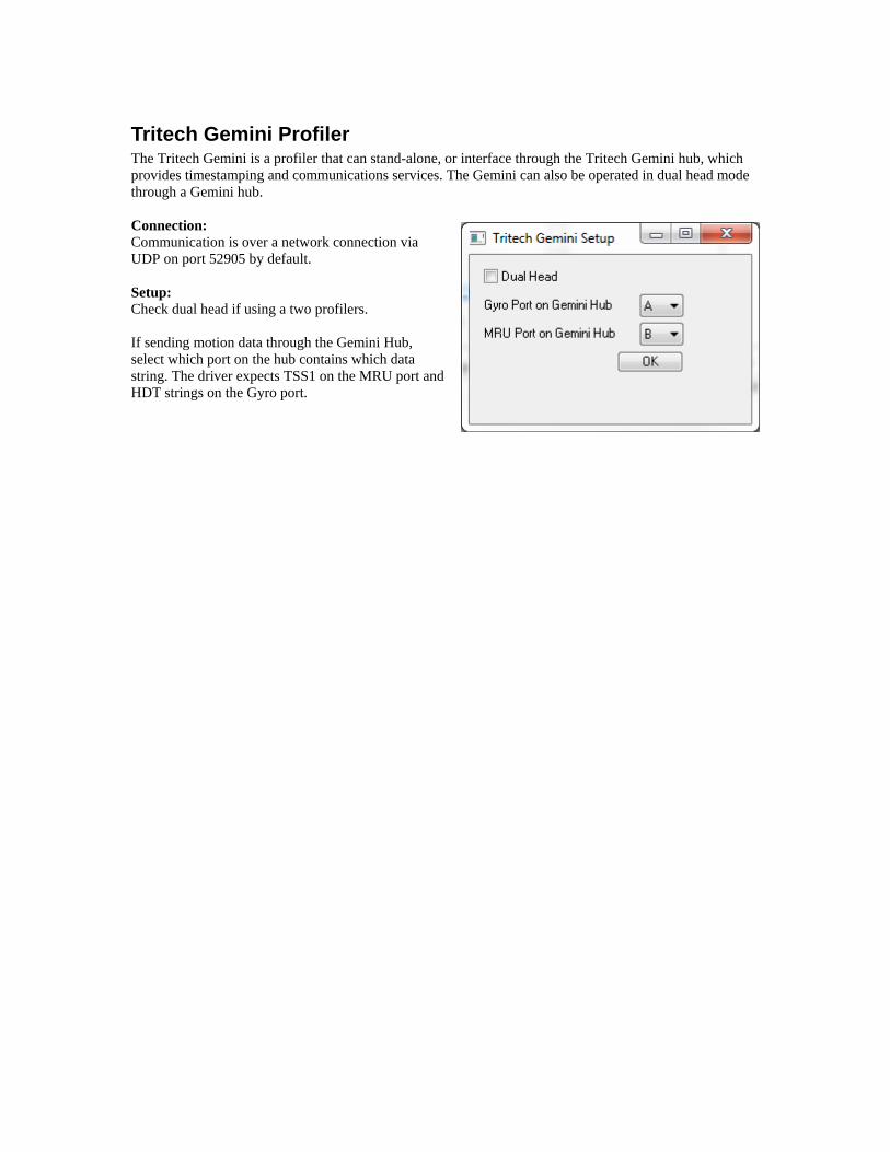
Tritech Gemini Profiler The Tritech Gemini is a profiler that can stand-alone, or interface through the Tritech Gemini hub, which provides timestamping and communications services. The Gemini can also be operated in dual head mode through a Gemini hub. Connection: Communication is over a network connection via UDP on port 52905 by default. Setup: Check dual head if using a two profilers. If sending motion data through the Gemini Hub, select which port on the hub contains which data string. The driver expects TSS1 on the MRU port and HDT strings on the Gyro port.
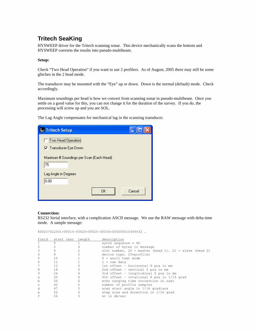
Tritech SeaKing HYSWEEP driver for the Tritech scanning sonar. This device mechanically scans the bottom and HYSWEEP converts the results into pseudo-multibeam. Setup: Check “Two Head Operation” if you want to use 2 profilers. As of August, 2005 there may still be some glitches in the 2 head mode. The transducer may be mounted with the “Eye” up or down. Down is the normal (default) mode. Check accordingly. Maximum soundings per head is how we convert from scanning sonar to pseudo-multibeam. Once you settle on a good value for this, you can not change it for the duration of the survey. If you do, the processing will screw up and you are SOL. The Lag Angle compensates for mechanical lag in the scanning transducer.
Connection: RS232 Serial interface, with a complication ASCII message. We use the RAW message with delta time mode. A sample message: %D0257022501+00015-00020+00025-00030+000000010404432 … field start char length description 1 0 1 synch sequence = %D 2 2 4 number of bytes in message 3 6 2 slot number, 20 = master (head 1), 21 = slave (head 2) 4 8 2 device type, 25=profiler 5 10 1 0 = ascii text mode 6 11 1 1 = raw data 7 12 6 1st offset - horizontal X pos in mm 8 18 6 2nd offset - vertical Y pos in mm 9 24 6 3rd offset - longitudinal Z pos in mm a 30 6 4th offset - rotational R pos in 1/10 grad b 36 6 echo ranging time correction in usec c 42 5 number of profile samples d 47 5 scan start angle in 1/16 gradians e 52 4 step size and direction in 1/16 grad f 56 5 sv in dm/sec

g 61 8 time at start of scan hhmmsshh h 69 5 duration of scan in msec i 74 3 000 = upright orientation j 77+5*# 5 range in useconds Pay attention that field 6 = 1 for raw data. Processed data has a different code and won’t work right. Offsets:
• Starboard: Sonar head location starboard of boat center. • Forward: Sonar head location forward of boat center. • Vertical: Sonar head location relative to waterline (positive). • Yaw, Pitch, Roll: Sonar head rotations relative to forward and vertical. Enter values determined
by patch testing. • Latency: Enter 0 – latency is automatically compensated.
Notes: Run the Sea King control program on the same computer as HYPACK/HYSWEEP to avoid timing problems. The serial connection is through a loop-back cable. .

TSS 335 HYSWEEP driver for the TSS 335B heave compensator. Provides heave, pitch and roll data. Connection: RS232 Serial interface, message format: :xxxxxx shhhhfsrrrr spppp<cr><lf> | | | | | | | | | ---- signed pitch in degrees * 100 | | | ----------- signed roll in degrees * 100 | | -------------- ? = bad heave | ----------------- signed heave in cm ------------------------ don’t care Offsets:
• Starboard: MRU location starboard of boat center. • Forward: MRU location forward of boat center. • Vertical: MRU location relative to waterline (positive below). • Yaw: Enter 0. • Pitch, Roll: Enter 0 (MRU pitch/roll offsets are typically zeroed within the MRU itself). • Latency: Enter 335B latency (0 if prediction mode, 0.07 seconds if not).
Notes: • If users want the option to record remote heave, they need to select the DMS or POS/MV driver
instead of the 335B driver (see below).

TSS DMS HYSWEEP driver for the TSS DMS/05, /10, etc. heave compensator. Provides heave, pitch and roll data. Setup Form:
Select TSS 1 Message for the text output message – heave, pitch and roll string similar to the DMS/05. Select TSS 3 Message to record remote heave instead of total heave as with the TSS1 message. Select Simrad EM1000 Message for binary output containing heave, pitch, roll and heading. Connection: RS232 Serial interface, message format: :xxxxxx shhhhfsrrrr spppp<cr><lf> | | | | | | | | | ---- signed pitch in degrees * 100 | | | ----------- signed roll in degrees * 100 | | -------------- don’t care | ----------------- signed heave in cm ------------------------ don’t care Offsets:
• Starboard: MRU location starboard of boat center. • Forward: MRU location forward of boat center. • Vertical: MRU location relative to waterline (positive below). • Yaw: Enter 0. • Pitch, Roll: Enter 0 (MRU pitch/roll offsets are typically zeroed within the MRU itself). • Latency: Enter 0.
Notes:

TSS POS/MV HYSWEEP driver for POS/MV heave, pitch, roll and heading data. Setup Form:
Select TSS 1 Message for the text output message – heave, pitch and roll string similar to the DMS/05. Select TSS 3 Message to record remote heave instead of total heave as with the TSS1 message. Select Simrad EM1000 Message for binary output containing heave, pitch, roll and heading. Connection: RS232 Serial interface. Offsets - MRU:
• Starboard: MRU location starboard of boat center. • Forward: MRU location forward of boat center. • Vertical: MRU location relative to waterline (positive below). • Yaw: Enter 0. • Pitch, Roll: Enter 0 (MRU pitch/roll offsets are typically zeroed within the MRU itself). • Latency: Enter 0.
Offsets - Gyro:
• Enter 0 for all offsets and latency. Notes:

Velodyne HDL-32E & VLP-16 High density laser device. The driver is a passive UDP network driver that reads XYZ lidar points from the data stream. Setup Form: None. During survey, check the "Use TOP Message" Logging Option to log full resolution data. If this option is turned off, HYSWEEP will automatically downsample as needed. Mounting: HYSWEEP has "vertical" and "horizontal" versions of the driver which are identical in operation except for the expected mounting. "Horizontal" assumes the device is mounted on top of the vessel with the head rotating 360° around the Z axis and the 0° point of the device aligned forward. "Vertical" assumes mounting on the stern of the vessel with the head rotating 360° around the forward (Y) axis and the 0° point of the device pointed upward. The 0° point on the HDL-32E is 90° from the cable; on the VLP-16, it is 180° from the cable. See the following diagrams from the Velodyne user manuals: The angle of rotation for the HDL-32E, looking down on the device from above:
The angle of rotation for the VLP-16, looking up at the device from below:

Connection: Via a network interface. Enter the IP of the device in the Connect tab. The default port is 2368. Control Form: The incoming point cloud can be thinned in real-time during survey with the filters provided on the HYSWEEP Velodyne controller. Note that these filters are on the HYPACK side and no commands are sent to the device. Points filtered by this method are lost--they are not displayed or logged. We recommend disabling all but the center beam (#16) during patch testing. Notes: Velodyne provides a web interface to configure the head rotation speed and other parameters. Simply point a web browser to the IP address of the device.
WASSP Multibeam Simple HYSWEEP driver for the WASSP Multibeam. Reads multibeam, gyro, and mru data from a network data stream. Not yet heavily tested and not recommended for use at this time. Setup Form: None. Connection: Via a network interface. Notes:
Appendix A: Analog Sidescan Interfacing Requires a multifunction I/0 device for port and starboard transducer signals + trigger, a cable and a connector block. All are available for from National Instruments, along with a CD containing driver software. National Instruments 11500 North Mopac Expressway, Austin, TX 78795-3504 TEL: (512) 794-0100 FAX: (512) 683-9300 www.ni.com I/O Board For Desktop Computers: NI PCI-6023E – PCI Board. For Notebook Computers: NI DAQ Card-6024E – PCMCIA Card Cable For the Desktop PCI Board: SH68-68-EP For the Notebook PCMCIA Card: SHC-68-68-EP Connector Block For either: SCB-68. To connect the three inputs – (1) port signal, (2) starboard signal, (3) trigger. Input Connector Block 1 Signal 68 (ACH0) 1 Ground 67 (AIGND) 2 Signal 33 (ACH1) 2 Ground 32 (AIGND) 3 Trigger 65 (ACH2) 3 Ground 64 (AIGND) Note: The trigger wiring below is obsolete as of HYPACK version 2.12A. 3 Signal 10 (PFI1/TRIG2) 3 Ground 9 (DGND) 11 (PFI0/TRIG1) connected to
47 (DIO3) for internal trigger test mode. Hardware / Software Installation • Before installing the NI-DAQ software, install the PCI-6023E board in a spare PCI
slot. • Start the computer and cancel the New Hardware Wizard. • Install the NI-DAQ software from CD then restart the computer.

• Upon restart, the PCI-6023E is automatically recognized and configured.

Appendix B: A Short List of Odd Things about HYSWEEP Interfacing • All offsets are considered corrections, that is they are added to the raw data. All offsets except the
MRU pitch and roll offsets. It got done that way a long time ago and it’s too late to change it now.

Appendix C: Interferometry Real-Time Processing As you may know, HYSWEEP has an internal limit of 1440 beams per ping for multibeam data. Of course, interferometry provides us many more points than that. Our task then is to intelligently reduce this data to something manageable by HYSWEEP which we accomplish through a combination of filtering and downsampling. Below is a screenshot of the new windows added to HYSWEEP. The “Interferometry” window displays all the points before any decimation. Points flagged as bad or filtered will be colored red; good data is colored green. It will also show any filter boundaries in blue if any are enabled.
Clicking the third button on this window will open the “Interferometry Options” window. This controls how HYSWEEP will process the data. The processing chain moves from the top of the form to the bottom. Once a point is flagged, it is ignored in the rest of the chain. Processing Options
• Avoid. These options allow you to skip some of the processing if the data is already sufficiently thin (ie < 1440 points). “Avoid Any Processing” will try to do nothing if it can. “Avoid Downsampling” will filter, but try not to beamform.
• Filtering. This section provides ways to remove noise. Typically one need
not use all of these. Points can be flagged on the basis of depth, offset, intensity, or quality code. If the sonar pre-flags bad points you have the option to honor or ignore these.
Display limits filters based on the depth, offset, and angle limits specified in the view options.
Manual limits allows you to specify limits that are not tied to your viewing limits. You can also set your offset limits to be a multiple of water depth.
Intensity and quality code simply filter by a specified min/max. Note that the drivers will scale intensity to a 0—32767 range and quality code to a 0—255 range. The meaning of these vary somewhat depending on the sonar.
The water column filter can track a single beam echosounder depth and reject points with a range less than that value.
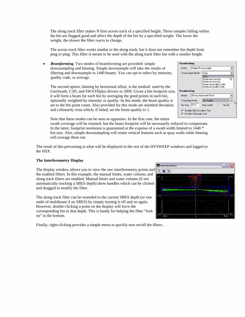
The along track filter makes N bins across track of a specified height. Those samples falling within the bin are flagged good and affect the depth of the bin by a specified weight. The lower the weight, the slower the filter reacts to change.
The across track filter works similar to the along track, but it does not remember bin depth from ping to ping. This filter is meant to be used with the along track filter but with a smaller height.
• Beamforming. Two modes of beamforming are provided: simple
downsampling and binning. Simple downsample will take the results of filtering and downsample to 1440 beams. You can opt to select by intensity, quality code, or average. The second option, binning by horizontal offset, is the method used by the GeoSwath, C3D, and SWATHplus drivers in 2009. Given a bin footprint size, it will form a beam for each bin by averaging the good points in each bin, optionally weighted by intensity or quality. In this mode, the beam quality is set to the bin point count. Also provided for this mode are standard deviation and colinearity tests which, if failed, set the beam quality to 1. Note that these modes can be seen as opposites. In the first case, the entire swath coverage will be retained, but the beam footprint will be necessarily reduced to compensate. In the latter, footprint resolution is guaranteed at the expense of a swath width limited to 1440 * bin size. Also, simple downsampling will retain vertical features such as quay walls while binning will average them out.
The result of this processing is what will be displayed in the rest of the HYSWEEP windows and logged to the HSX. The Interferometry Display The display window allows you to view the raw interferometry points and the enabled filters. In this example, the manual limits, water column, and along track filters are enabled. Manual limits and water column (if not automatically tracking a SBES depth) show handles which can be clicked and dragged to modify the filter. The along track filter can be reseeded to the current SBES depth (or raw nadir of multibeam if no SBES) by simply turning it off and on again. However, double-clicking a point on the display will force the corresponding bin to that depth. This is handy for helping the filter “lock on” to the bottom. Finally, right-clicking provides a simple menu to quickly turn on/off the filters.