hypstair –system architecture, certifiability and safety ... · the hypstair system design...
TRANSCRIPT

HYPSTAIR – System Architecture, Certifiabilityand Safety AspectsSymposium E²-Fliegen 2016, Stuttgart
www.siemens.com© Siemens AG 2016

Restricted © Siemens AG 201618.02.2016Page 2 Heintje Wyczisk, Claus Zeumer / CT REE AIR
Contents
• The HYPSTAIR Propulsion System – Design Approach
• The HYPSTAIR Propulsion System – Architecture & Components
• The HYPSTAIR Propulsion System – Built-in Redundancy
• Technical & Regulatory Challenges for Novel Designs
Restricted © Siemens AG 201618.02.2016Page 3 Heintje Wyczisk, Claus Zeumer / CT REE AIR
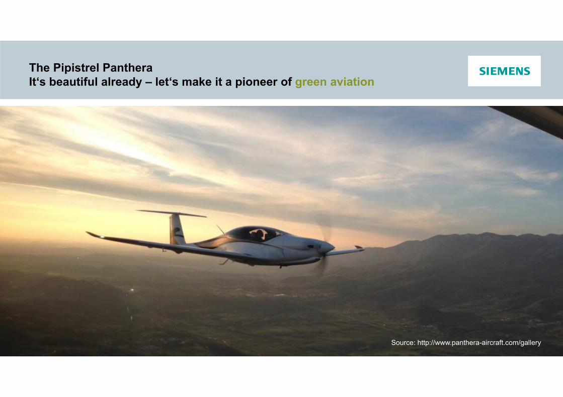
The Pipistrel PantheraIt‘s beautiful already – let‘s make it a pioneer of green aviation
Source: http://www.panthera-aircraft.com/gallery
Restricted © Siemens AG 201618.02.2016Page 4 Heintje Wyczisk, Claus Zeumer / CT REE AIR
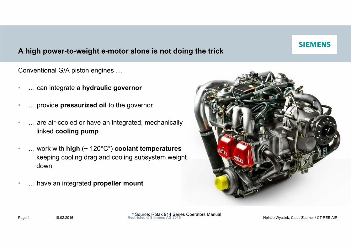
A high power-to-weight e-motor alone is not doing the trick
Conventional G/A piston engines …
• … can integrate a hydraulic governor
• … provide pressurized oil to the governor
• … are air-cooled or have an integrated, mechanicallylinked cooling pump
• … work with high (~ 120°C*) coolant temperatureskeeping cooling drag and cooling subsystem weightdown
• … have an integrated propeller mount
* Source: Rotax 914 Series Operators Manual

Restricted © Siemens AG 201618.02.2016Page 5 Heintje Wyczisk, Claus Zeumer / CT REE AIR
The HYPSTAIR System Design Approach: Aircraft-Level Optimization
FunctionalIntegration
Power
Safety
Overall Weight
Efficiency
CoolingDrag
Propulsion System
Optimum at AircraftLevel
Restricted © Siemens AG 201618.02.2016Page 6 Heintje Wyczisk, Claus Zeumer / CT REE AIR
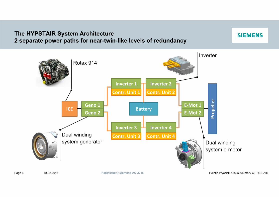
The HYPSTAIR System Architecture2 separate power paths for near-twin-like levels of redundancy
ICE
Inverter 1 Inverter 2
Battery
Prop
eller
Inverter 3 Inverter 4
Geno 1 E‐Mot 1Geno 2 E‐Mot 2
Contr. Unit 1 Contr. Unit 2
Contr. Unit 3 Contr. Unit 4Dual windingsystem e-motor
Dual windingsystem generator
Rotax 914Inverter

Restricted © Siemens AG 201618.02.2016Page 7 Heintje Wyczisk, Claus Zeumer / CT REE AIR
The HYPSTAIR Components
Siemens Generator – 100kW MCP
• LIGHTWEIGHT Power density 5,3 kW/kg
• SAFE Redundant winding system
• ROBUST 90 - 105°C coolant inlet temperature
• EFFICIENT > 95% at cruise power
• HIGH LEVEL OF INTEGRATION• Acts as ICE starter• Acts as ICE flywheel

Restricted © Siemens AG 201618.02.2016Page 8 Heintje Wyczisk, Claus Zeumer / CT REE AIR
The HYPSTAIR Components
Siemens NextGen Converter – 100 kVA
• LIGHTWEIGHT power density of 10,5 kW/kg
• EFFICIENT = 98%
• ROBUST 85 ºC coolant temperature
• SMART Integrated Central Control Unit for
• Inverter Control Functions• Central Control Functions
Restricted © Siemens AG 201618.02.2016Page 9 Heintje Wyczisk, Claus Zeumer / CT REE AIR
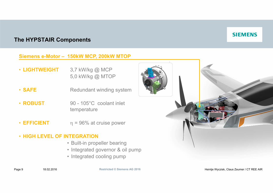
The HYPSTAIR Components
Siemens e-Motor – 150kW MCP, 200kW MTOP
• LIGHTWEIGHT 3,7 kW/kg @ MCP5,0 kW/kg @ MTOP
• SAFE Redundant winding system
• ROBUST 90 - 105°C coolant inlet temperature
• EFFICIENT = 96% at cruise power
• HIGH LEVEL OF INTEGRATION• Built-in propeller bearing• Integrated governor & oil pump• Integrated cooling pump
Restricted © Siemens AG 201618.02.2016Page 10 Heintje Wyczisk, Claus Zeumer / CT REE AIR
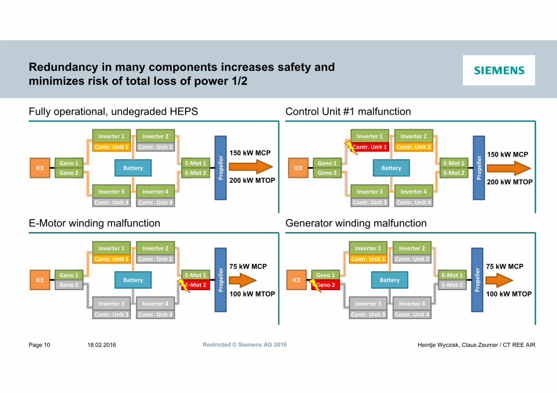
Redundancy in many components increases safety andminimizes risk of total loss of power 1/2
Fully operational, undegraded HEPS Control Unit #1 malfunction
E-Motor winding malfunction
ICE
Inverter 1 Inverter 2
Battery
Prop
eller
Inverter 3 Inverter 4
Geno 1 E‐Mot 1Geno 2 E‐Mot 2
Contr. Unit 1 Contr. Unit 2
Contr. Unit 3 Contr. Unit 4
150 kW MCP
200 kW MTOP
ICE
Inverter 1 Inverter 2
Battery
Prop
eller
Inverter 3 Inverter 4
Geno 1 E‐Mot 1Geno 2 E‐Mot 2
Contr. Unit 1 Contr. Unit 2
Contr. Unit 3 Contr. Unit 4
150 kW MCP
200 kW MTOP
Generator winding malfunction
ICE
Inverter 1 Inverter 2
Battery
Prop
eller
Inverter 3 Inverter 4
Geno 1 E‐Mot 1Geno 2 E‐Mot 2
Contr. Unit 1 Contr. Unit 2
Contr. Unit 3 Contr. Unit 4
75 kW MCP
100 kW MTOP
ICE
Inverter 1 Inverter 2
Battery
Prop
eller
Inverter 3 Inverter 4
Geno 1 E‐Mot 1Geno 2 E‐Mot 2
Contr. Unit 1 Contr. Unit 2
Contr. Unit 3 Contr. Unit 4
75 kW MCP
100 kW MTOP

Restricted © Siemens AG 201618.02.2016Page 11 Heintje Wyczisk, Claus Zeumer / CT REE AIR
Redundancy in many components increases safety andminimizes risk of total loss of power 2/2
Battery malfunction Combustion Engine malfunction
ICE
Inverter 1 Inverter 2
Battery
Prop
eller
Inverter 3 Inverter 4
Geno 1 E‐Mot 1Geno 2 E‐Mot 2
Contr. Unit 1 Contr. Unit 2
Contr. Unit 3 Contr. Unit 4
120 kW
ICE
Inverter 1 Inverter 2
Battery
Prop
eller
Inverter 3 Inverter 4
Geno 1 E‐Mot 1Geno 2 E‐Mot 2
Contr. Unit 1 Contr. Unit 2
Contr. Unit 3 Contr. Unit 4
75 kW MCP
75 kW MTOP
Inverter malfunction
ICE
Inverter 1 Inverter 2
Battery
Prop
eller
Inverter 3 Inverter 4
Geno 1 E‐Mot 1Geno 2 E‐Mot 2
Contr. Unit 1 Contr. Unit 2
Contr. Unit 3 Contr. Unit 4
75 kW MCP
100 kW MTOP
Technical & RegulatoryChallenges for NovelHEPU / EPU Designs
www.siemens.com© Siemens AG 2016
Restricted © Siemens AG 201618.02.2016Page 13 Heintje Wyczisk, Claus Zeumer / CT REE AIR
Technical Challenges of Novel EPU/HEPU Designs
Principle design aspects: Development of sustainable airborne application concepts for electrical machines & power electronics Availability of high power dense energy sources > 500 Wh/kg Application optimized ICE concepts Reduction of overall system complexity Higher EPU/HEPU integration level to airframe designs Structural weight optimization of passive parts e.g. usage of alternative materials
Reliable safety concepts to: Avoid thermal runaway conditions of high voltage batteries Operate „safe & redundant“ control system architectures (HW / SW) Reliable and usefully HMI concepts Realize electrical security using high voltage in aircraft > 1.000 V (AC/DC) Enable the usage of power electronics at high altitudes considering cosmic radiation effects, etc. …
Efficient cooling system concepts for: Operational temperature and air density range High voltage batteries get max power output / time Electrical machines & power electronics to realize high power density
Restricted © Siemens AG 201618.02.2016Page 14 Heintje Wyczisk, Claus Zeumer / CT REE AIR
Sources for Electric Flight Certification Basis
EASA sources for electric powered a/c:
- CS-22 motor gliders (SC-22.2014-01)- EASA CS-LSA Issue 1 (referring to ASTM F2840)
- DO-311(A) Minimum Operational Performance Standards for Rechargeable Lithium Battery Systems
- SAE J2464 Electric and Hybrid Electric Vehicle Rechargeable Energy Storage System Safety and Battery Abuse Testing
- EASA CRI F-58 - Lithium Battery Installations
- LBA SC Brennstoffzellen 3. Ausgabe April 2012
- ASTM F2840 - 14- ASTM F44.40 WG Integration (wip)- ASTM F39.05 WG EPU&HEPU (wip)
- Industrial Standards & Specs - DIN 29576, MIL-HDBK-274…
- FAA Electric Propulsion – A Regulatory Feasibility Study- Austro Control – Guideline for Installation & Certification
- CS-E / CS-23 (incl. A-NPA 2015-06, planned publ. Q2/2016)
- AC23.1309 System Safety Analysis and Assessment for Part 23 Airplanes
- AC23.1311 Installation of Electronic Display in Part 23 Airplanes
- AC23.1521 –Type Certification of Automobile Gasoline in Part 23 Airplanes with Reciprocating Engines
- AC23-2 Flammability Tests
- ARP-4754 / ED-79 System Development Process- ARP-4761 Safety Assessment
- DO-160G/ ED-14 Environmental conditions and test procedures
- DO-254/ED-80 Electronic HW Development Process- DO-264- DO-200A / DO-201A Airborne Databases- DO-178C / ED-12 Software considerations in Airborne
Systems and Equipment Certification

Restricted © Siemens AG 201618.02.2016Page 15 Heintje Wyczisk, Claus Zeumer / CT REE AIR
Regulatory Challenges of EPU/HEPU Designs
Design & Airframe integration aspects: only basic regulations / proposals are available … ASTM F2840-14 CS-22H SC‘s / CRI‘s A-NPA’s Guidance material …
• … but don‘t cover yet the full range of required regulatory frame for sustainable HEPU / EPU product development & certification base (future airworthiness design standards)
Adaptation/inclusion of existing regulatory frame (CS-x) to new technology need to be simplified and easy traceable (e.g. same CS-x numbering vs. trace matrix for more transparency & less complexity, especially important for aviation novices)
Standard (ELOS) interpretation of conventional airworthiness requirements are only partly usable/reasonable, because of new technology aspects ( new AMC‘s / guidance material required)
Current initiatives like ASTM with initially transparent process for re-writing FAR-23 making slow progress, because of low willingness to invest significant effort, but political interest very high

Restricted © Siemens AG 201618.02.2016Page 16 Heintje Wyczisk, Claus Zeumer / CT REE AIR
Thank you for your attention !
siemens.com
Claus Zeumer
Project Manager eAircraftCT REE AIR PROM
Günther-Scharowsky-Str. 191058 Erlangen
Phone: +49 (9131) 7-22139Fax: +49 (9131) 7-28179Mobil: +49 (173) 6394415
E-Mail: [email protected]
Heintje Wyczisk
Head of Certification & ProcessesCT REE AIR CR
Günther-Scharowsky-Str. 191058 ErlangenPhone: +49 (9131) 7-27955Fax: +49 (9131) 7-28173Mobil: +49 (174) 3135942
E-Mail: [email protected]