hypervelocity flow research in ballistic range
TRANSCRIPT

24TH INTERNATIONAL CONGRESS OF THE AERONAUTICAL SCIENCES
1
Abstract
Hypervelocity flow studies using ballistic range facility are underway as a collaboration research project of Tohoku University and Mitsubishi Heavy Industries for several years. Preliminary results from two research projects are presented in this paper. First project is the experimental study of shock on shock interaction phenomena in front of the double cone projectile in hypersonic regime. Laser holographic interferometry was used to visualized the flow field around the double cone shaped projectile. The interferogram shows that the several fringe shifts can be obtained even with 15mm diameter projectile. The experimental result was compared with the numerical computation results. The agreement between them was found to be very good to each other. Second project is the blunt body flow and wake flow in carbon dioxide. The flow field was visualized with multi-direction schlieren movie. The comparison between flow field of air and carbon dioxide is discussed qualitatively as a preliminary study.
1 Introduction In 2002, the new Ballistic Range facility was introduced to Institute of Fluid Science (IFS) of Tohoku University. This facility was designed to use not only for structural impact studies but also high speed aerodynamic experiments by using 12m long test tank which enables to obtain the relatively long free-flight time. The ballistic range facility has several merits for high speed aerodynamic experiments especially
for hypervelocity regime tests. One is the chemical composition of the flow. Many of the other type of impulse facility, such as free piston driven shock tunnel, have the setback of the existence of un-recombination atoms in the nozzle flow [1, 2]. But in the ballistic range, the projectile is launched into well-controlled still gas, therefore, the chemical composition of the test gas can be easily controlled. Another main advantage of this facility is to be able to visualize the wake flow because the model-supporting sting is not necessary. Several high speed aerodynamic experimental studies were conducted at IFS by utilizing these merits [3]. But the test condition was limited in the previous work due to the length of the test tank which limits the testing time. One of the main objectives of the study is to extend the experimental condition toward the high velocity regime. This paper describes the preliminary results from experiments of shock on shock interaction and blunt body flow in carbon dioxide.
2 Experimental Method
2.1 Ballistic Range Facility
This facility has three operation modes, two-stage light gas gun, single-stage powder gun and single-stage light gas gun, depending on its requirements from the velocity range of the experimental projects. As for the single-stage powder gun, the diameter of the projectile can be selected from 15mm and 51mm. The other
HYPERVELOCITY FLOW RESEARCH IN BALLISITIC RANGE
Kenji TOGAMI*, Tokitada HASHIMOTO**, Kazuyoshi TAKAYAMA***
*Nagoya Aerospace Systems Works, Mitsubishi Heavy Industries, LTD., **Japan Aerospace Exploration Agency,
***Institute of Fluid Science, Tohoku University.
Keywords: Ballistic Range, Hypervelocity Flow, Reentry, Wake Flow, Shock Wave

Togami, K, Hashimoto, T and Takayama, K.
2
configurations can be operated with 15mm diameter projectile. The schematic of the facility is shown in figure 1. The powder chamber for two-stage operation can contain maximum 900grams of propellant powder. The length of the compression tube is 4m and its bore diameter is 50mm. The acceleration tube is 3m in length and 15mm in diameter. Both tubes are connected at the high-pressure coupling assisted by hydraulic system
which reduces the human labor. The hydraulic pressure which resists the compressed driver gas pressure is 62MPa (9000psi). The length of the test tank is 12m. With this tank, more than milliseconds of free-flight time can be obtained even in the condition of 5km/sec of the projectile velocity. This test tank has 3 pairs of flanges that are used for optical visualization and another 3 pairs of flanges used for flash X-Ray radiography.
Propellant chamber
High pressure coupling
Launch tube
Test section
X-ray diagnostics
Specification Pump tube i.d.: 51 mm Length: 3.4 m Launch tube i.d.: 15 mm Length: 3 m Test section i.d.: 1.8 m Length: 12 m
Fig.1. Schematic View of Ballistic Range Facility at IFS
2.2 Test Chamber Small test chamber was placed in the tank equipped with optical windows for visualization. Figure 2 shows the overview of the test chamber. This tank has inlet and exit covered with replaceable thin diaphragm broken by the projectile during the experiment. Several materials of the diaphragm were tested not to damage the projectile and not to produce so many fragments which disturb the flow field. The diameter of the optical windows on this chamber is 200mm.
Projectile direction
Projectile inlet area
Optical window
Fig. 2. Test Chamber
2.3 Optical Systems
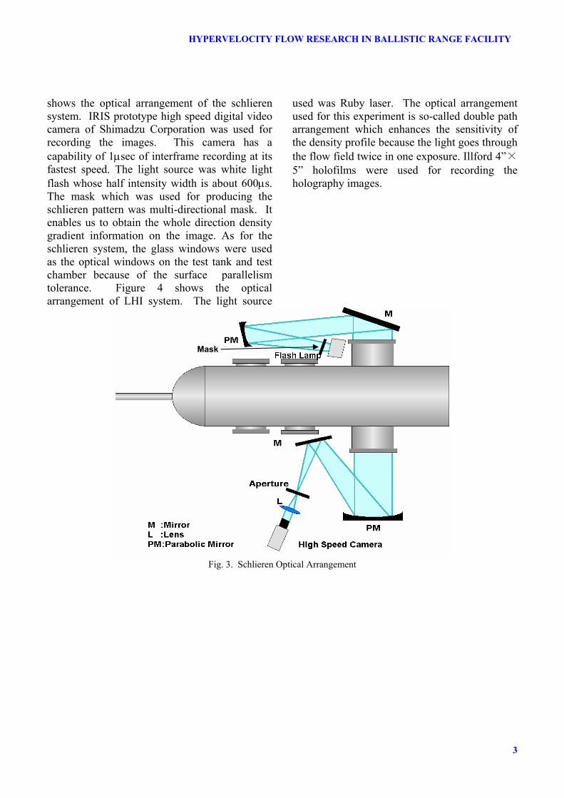
Optical flow visualization is the most powerful tool to obtain the aerodynamic data from the experimental results from ballistic range facility. Two methods of the visualization were used during this experimental series. One is schlieren method and the other is double exposure laser holographic interferometry (LHI). Figure 3
Pump tube Velocity Measurement Flange
Optical Window
3
HYPERVELOCITY FLOW RESEARCH IN BALLISTIC RANGE FACILITY
shows the optical arrangement of the schlieren system. IRIS prototype high speed digital video camera of Shimadzu Corporation was used for recording the images. This camera has a capability of 1µsec of interframe recording at its fastest speed. The light source was white light flash whose half intensity width is about 600µs. The mask which was used for producing the schlieren pattern was multi-directional mask. It enables us to obtain the whole direction density gradient information on the image. As for the schlieren system, the glass windows were used as the optical windows on the test tank and test chamber because of the surface parallelism tolerance. Figure 4 shows the optical arrangement of LHI system. The light source
used was Ruby laser. The optical arrangement used for this experiment is so-called double path arrangement which enhances the sensitivity of the density profile because the light goes through the flow field twice in one exposure. Illford 4”×5” holofilms were used for recording the holography images.
Fig. 3. Schlieren Optical Arrangement
Mask

Togami, K, Hashimoto, T and Takayama, K.
4
Fig. 4. Laser Holographic Interferometry Optical Arrangement
2.5 Projectiles
Two shapes of the projectiles were used for the preliminary study. One projectile is double cone configuration to study shock on shock interaction phenomena. The semi-apex angles of the double cone are 25 degree and 50 degree respectively. This shape is taken from ref [4]. The picture of the double cone projectile is shown figure 5.
Fig. 5. Double Cone Projectile
The other projectile we used was the spherically blunted cylinder. This projectile is shown in figure 6.
Fig. 6. Spherically Blunted Cylinder Projectile
The material for both projectiles were Polycarbonate which could resist the shock at the launch from the gun. The bottom diameter of the projectile is slightly larger than the bore diameter of the acceleration tube to seal the gas pressure to obtain the good acceleration.
2.6 Velocity Measurement
Projectile velocity was measured with laser beam cutting methods. The schematic of the velocity measurement apparatus is shown in figure 7.

5
HYPERVELOCITY FLOW RESEARCH IN BALLISTIC RANGE FACILITY
Fig.7. Schematic of Laser Cut Velocity Measurement
Two laser beams were set normal to the trajectory of the projectile to be cut by the projectile while experiment. The photo diode is used to measure the laser intensity coming through the exhaust tube and the signal from the diode tells the time when the projectile goes through the place where the laser goes through. The sample signal output from this system is shown in figure 8.
Fig. 8. Sample output of laser velocimetry
Laser Cut Velocimetry Diaphragm
Blast Tube
Digital Recorder
Test Chamber
Projectile
Optical Window
Digital Delay
Optics
-0.1
0
0.1
0.2
0.3
0.4
0.5
0 0.2 0.4 0.6 0.8 1
UpstreamDownstream
Out
put a
mpl
itude
(V)
Time (msec)
Time of projectile
∆t
Projectile velocity=Laser interval÷∆t =0.2m÷0.51msec=390m/sec

Togami, K, Hashimoto, T and Takayama, K.
6
3 Experiments and Numerical Simulation
3.1 Diaphragm Material Selection
Since the projectile goes through the diaphragm, the material and the thickness of the inlet diaphragm of the test chamber should have been carefully considered. Two materials were used to visualize the fragment from the diaphragm, MylarTM and cellophane. The flow visualization results from these two diaphragm materials are shown in figure 9. The image was taken with 4µsec interframe rate and the exposure time is 0.5µsec. The image shown below is every 4 frames. The projectile velocity was set to be 1.83km/sec and the pressure difference of the both side of the diaphragm was set to be less than 10Pa. The thickness of the diaphragm is 20µm for both cases.
From these results, the MylarTM diaphragm produced less fragments into the flow field compared to the result with cellophane diaphragm. Therefore, the MylarTM diaphragm was used for the following experiments.
(a) Cellophane Diaphragm (u=1.83km/sec, p=18kPa)
(b) MylarTM Diaphragm (u=1.83km/sec, p=87kPa)
Fig. 9. Sequential Schlieren Images of Double Cone Projectile and Diaphragm Fragments
(This figure shows every 4 frames that is every 16µs.)

Togami, K, Hashimoto, T and Takayama, K.
3.2 Shock on Shock Interaction Study Shock on shock interaction is very important for the thermal design of reentry vehicle because the interaction pattern strongly governs the aerodynamic heating into the surface of the reentry vehicle. Many experimental, theoretical and numerical investigations were carried out to understand this phenomenon. The most comprehensive study was conducted by Edney[5]. The shape of the projectile was designed to reproduce type-V of shock on shock interaction pattern according to this reference. The schematic of the flow field structure is shown in figure 10. The intention to choose this interaction pattern is to compare the results with the results from free-piston driven shock tunnel from ref. [4].
Fig. 10. Type-V Shock on Shock Interaction on Double Cone/Wedge.
3.2.1 Experiment The experimental condition is shown in table 1.
Table 1. Experimental Condition Velocity (km/sec) 1.9
Pressure (kPa) 17 Temperature (K) 283
Test Gas Air Re (based on diameter) 3.2 x 10⁵
Flow visualization result from LHI is shown in figure 11.
Fig.11. LHI Images of Flow Field around Double Cone Projectile
The weak fringe on the 1st conical part can be observed and it is considered to be the density variation due to the flow separation. And the curved shock in front of the 2nd conical part is also observed. This is due to the existence of the subsonic region in front of the 2nd cone.
3.2.2 Comparison with Numerical Simulation To examine the shock layer structure, numerical simulation was conducted. This computation is based on thermally and chemically nonequilibrium Navier-Stokes equations with Park’s two temperature model. Chemical reaction model is composed of five species, 17 chemical reactions. The governing equation is discretized with flux vector splitting method and the discrete equation is solved by single line Gauss-Seidel matrix solver. More detail of the computation code is described in ref. [6]. Computational grid is shown in figure 11. The grid is composed of 56 times 100 cells.

Togami, K, Hashimoto, T and Takayama, K.
8
Fig.12. Computational Grid
The computed Mach number profile is shown in figure 13.
Fig. 13. Mach Number Profile from Computation
From this figure, it is understood that the computation can reproduce the existence of both subsonic and supersonic region in front of the 2nd cone. But the shape of the shock in front of the 2nd cone is slightly different from the experimental result shown in figure 11. Shock inflection can be observed in LHI image but no inflection point is observed in figure 13. This is considered to be due to the difference in the location of the separated shock though the weak compression wave can be observed from the upstream of the junction point of 1st and 2nd cone. From this difference of the location of the separation shock, the shock interaction pattern is
slightly different from the experimental results. This existence of the flow separation region itself can be confirmed by velocity vector shown in figure 14.
Fig.14. Velocity Vector of Separated Zone
3.3 Blunt Body Flow in Carbon Dioxide Hypervelocity flow research in carbon dioxide is necessary to design the planetary entry vehicle to Mars. Since the molecule of carbon dioxide is composed of three atoms therefore the vibration mode of the molecule is much more complicated than air which is composed of molecules from two atoms. In addition to that, the atomic oxygen is easily produced from dissociation because of its relatively low specific enthalpy. So, the test with carbon dioxide in reflected shock tunnel makes more damage to the facility. For that reason, the ballistic range is suitable facility to do experiment with carbon dioxide. Experimental conditions are shown in table 2. Similar experiment with air was also conducted as a reference test.
Table 2. Experimental Condition with Blunt Body
Test Gas CO2 Air Velocity (km/s) 2.0 1.7
Pressure (Pa) 300 300 Temperature (K) 283 285 Mach Number 8.0 5.0
Re based on base diameter. 1.0 x 10⁵ 5.1 x 10⁴
Specific Heat Ratio 1.3 1.4 Flow field was visualized multi direction schlieren method by using high speed digital video camera described in section 2.3.
Flow Separation

9
HYPERVELOCITY FLOW RESEARCH IN BALLISTIC RANGE FACILITY
The result is shown in figure 15.
(a) Test with Carbon Dioxide
(b) Test with Air
Fig. 15. Consecutive Schlieren Images of Blunt Projectile In all carbon dioxide cases including the case not shown in this paper, the black powder-like wake can be observed along the trajectory of the projectile. This is considered as the carbon deposition due to the chemical reaction mainly in the shock layer in front of the projectile. Further study is necessary to confirm this explanation. As for the wake structure, recompression shock wave can be observed in both cases. But the location of the recompression is slightly different. The location of the recompression shock in carbon dioxide case is close to the base of the projectile. This distance is about 20% less than air. This is due to the difference in the specific heat ratio due to the difference in molecular structure and also due to the difference in Mach number of the flow field. This can be qualitatively explained by calculating Prandtl-Meyer Function shown below.
( ) ( ) ( )1tan111tan
11, 2121 −−−
+−
−+
= −− MMMγγ
γγγν (1)
The value of this function in carbon dioxide case is larger than that of air. Therefore, the expanding angle at the projectile base is considered to be larger in carbon dioxide case. Therefore, the starting location of the
recompression shock is closer to the base of the projectile in carbon dioxide case than in air case.
4. Conclusions Preliminary results of hypervelocity experiments in ballistic range facility are presented. (1) Quantitative investigation was conducted in
shock on shock problem in air and was found that the numerical result shows good agreement with experimental result.
(2) The difference in wake flow of air and carbon dioxide were shown experimentally. The difference could be explained qualitatively with simple 1D Prandtl-Meyer expansion equation.
(3) It is shown that ballistic range is a powerful tool for high speed aerodynamic research especially for wake flow studies.
Acknowledgement The authors wish to acknowledge Mr. Kusano at Shimadzu Corporation who provided us to use the prototype high-speed digital video camera that is under development. Also we would like to express our gratitude to Mr. Yamashita from Chugoku Kayaku, Dr. Sturtzer, Mr. Ogawa and Mr. Ojima at IFS for their help for the

Togami, K, Hashimoto, T and Takayama, K.
10
experiments. This work is partly supported by the grant from COE program of the Ministry of Education, Culture, Sports, Science and Technology.
References [1] Park, C., Assessment of two-temperature kinetic
model for ionizing air, Journal of Thermophysics and Heat Transfer, Vol.3, pp.233-244, 1989.
[2] Stalker, R. J., Hypervelocity aerodynamics with chemical nonequilibrium, Annual Review of Fluid Mechanics, Vol.21, pp37-60, 1989.
[3] Nonaka, S., Experimental and Numerical Study on Hypersonic Flows in Ballistic Range, Dr. Eng. Thesis, Faculty of Engineering, Tohoku University, 2000.
[4] Hashimoto, T., Analytical and experimental study of hypersonic nozzle flows in free piston shock tunnel, Dr. Eng. Thesis, Faculty of Engineering, Tohoku University, 2003.
[5] Edney, B., Anomalous heat transfer and pressure distributions on blunt bodies at hypersonic speeds in the presence of an impinging shock, FFA Rep.115, 1968.
[6] Togami, K., Study of aerodynamic heating on finite catalytic surface, Dr. Eng. Thesis, Faculty of Engineering, University of Tokyo, 2003.