hypervelocity impact (hvi) tests and signal recordings
TRANSCRIPT
Universal Journal of Aeronautical & Aerospace Sciences 2 (2014), 80-113 www.papersciences.com
80
Hypervelocity Impact (HVI) Tests & Signal Recordings
L. E. Iliescu, A. A. Lakis and A. Abou – Antoun Department of Mechanical Engineering, École Polytechnique de Montréal
C.P. 6079, Succ. Centre-Ville, Montréal Québec, Canada H3C 3A7
Abstract Among the other hazards that occur in space environment, due to the increased space activity, especially the intensification of spacecraft lunches but also to the poor standardization of space activity or lack of means in cleaning the space environment from space debris and non-functional satellites, the number of potential micrometeoroid and orbital debris impact continue to grow exponentially, fact that could render the space in-utilizable in the next decades. The aim of this paper, as a part of larger work, is to present the experimental part that was performed in order to acquire valid vibrational signals that afterwards will be studied using an in-house signal analysis software in order to determine in real-time the characteristics of hypervelocity impact damage. Starting from the selection of materials which are used mostly for the impact protection systems but also for the spacecraft structure and from of thoroughly review of impact detection technologies, six hypervelocity tests was performed in low-velocity regime on aluminum and carbon fiber targets. As a result, valid recordings of accelerations were obtained from the sensors mounted on the targets and outside of testing chamber. Moreover, the experimental session permitted to have an insight in preparation of this type of tests, specific to space debris hypervelocity impact, as well as the particularities in performing the test and acquiring useable signal for further analysis. Key Word and Phrases Hypervelocity Impact, Orbital Debris, Vibrational Signals, Collision Risk, Damage Tests.
1. Introduction Every satellite or space vehicle launched in space has the potential to create orbital debris. Any
hypervelocity impact between two objects of sizeable mass can spall off a debris cloud and secondary eject from the force of collision. Each piece of material resulting from the impact has the potential to cause further damage, creating even more space debris. If the collision is large (i.e. between a space station and a defunct satellite), the amount of cascading debris could be enough to render Low Earth Orbit essentially unusable. Damage due to smaller debris has now grown to become a significant problem in its own right. Chipping of the windows of the space shuttle along with minor damage to its thermal protection system tiles (TPS) became common by the 1990s.
There are currently more than 22,000 pieces of orbital debris that are tracked and their presence around the planet poses a high collision risk to valuable satellites and other spacecraft. Considering that space debris is largely uncharacterized, it is hard to protect against it. Using existing technology, debris with sizes in the 1 to 5 cm range cannot be detected and tracked. Although most debris will burn up in the atmosphere, larger objects can reach the ground intact and present a risk. A lack of test data poses a threat to the detection of space debris. In addition, some research work is classified or only preferentially shared.
Improved definition and characterization of orbital debris (OD) through development of HVI testing capabilities to over 10 km/s and high strain modeling hydro-codes is a major international issue. An additional global challenge is the development of new light materials and new design configurations offering protection against OD in the 1 to 5 cm range.
The damage and debris generated by an MMOD impact is a complex phenomenon that involves resolving problems such as shock and dynamic material behaviour. In the case of an aluminum

L.E. Iliescu, A.A. Lakis & A.Abou–Antoun
shield, for example, the collision creates a nearly hemispherical crater and, depending on the thickness used, internal fracturing or attached/detached spallation.
The aim of this document is to provide a synthesis of knowledge and experience on the HVI impact test and damage. Tests were performed at the Shock Wave Physics laboratory of McGill University with respect to spacecraft protection against orbital debris and micro-meteoroids. The primary objective of the paper is to capture results and signal recordings of the tests. This document provides a framework that allows further time- frequency analysis of the signals in order to produce a real-time detection of different types of HVI damage. More specifically, this paper provides a short literature review of materials used in MMOD protection, a summary of sensor types used to detect HVI impact damage, a description of the impact facility and recorded test data/results.
This document is the first part of a larger work that will include; TF analysis of signals, HIV tests at higher speeds (up to 8 km/s) and the use of fiber glass (FBG) sensing technology to enable accurate detection of HVI damage in real time.
2. Literature review of micrometeoroids and orbital debris (MMOD) and impact protective materials
2.1. General consideration
A short literature review summary is presented to describe the characteristics of materials that are generally used to shield against high velocity impacts. To assess the potential of various types of materials for use as protection against MMOD impact, a significant number of tests should be carried out and the results compared to a baseline material, usually Al6061T6.
E. L. Christiansen [1] performed a series of 66 HVI tests to assess the potential of various materials such as aluminum, titanium, copper, stainless steel, nickel, nickel/chromium, reticulated vitreous carbon, silver, ceramic, aramid, ceramic glass, and carbon fibre. In addition, structures such as monolithic plates, open-cell foam, flexible fabrics and rigid meshes, arranged in various single or multiple bumper configurations were tested to evaluate their effectiveness as MMOD shielding.
The performance of these materials and structures was evaluated through target damage assessment reported to their respective weight. Cour-Palais [2] presents one of the first reviews of HVI on metallic, glass and composite materials. The paper describes in detail the impact damage phenomena on these materials. Schonberg [3] presents the results of several tests performed on different composite materials, taking into consideration the advantages and disadvantages of using composites in MMOD shielding structures. The results show that composite materials perform differently depending upon their location within the shielding structure. The conclusion was drawn that the use of composite materials in combination with metallic materials such as aluminum in a shielding structure can significantly increase MMOD impact protection compared with traditional all-metallic structures of similar weight. K. Fuji [4] performs HVI in a very low-velocity regime (500–1230 m/s) using a steel sphere as a projectile and analyzes the perforation behaviour of targets of different carbon fibers, interlaminate sequences and configurations (cross-ply, woven cloths, or thickness).
The paper analyzes the damage mechanism from the point of view of absorbed energy using high speed cameras and after-shot observations and concludes that fracture mechanisms occur in different manners depending on the thickness, strength and fracture strain fiber of the sample. A detailed examination was also made of the fracture on the rear and front faces of the sample (corroborated with delamination) depending on the impact energy.
Y. Nagao [5], through the measurement of collision fractures, internal damage and residual compression strength, reports a relation between collision energy and damaged area based on the results of HVI and non-destructive tests. Compression tests showed that the residual strength depends on plate thickness when it is not perforated. In the case of a perforation, a plate of different thickness has the same residual strength. Also, a reduction in residual strength is caused by the many cracks that occur inside the laminar.
81

L.E. Iliescu, A.A. Lakis & A.Abou–Antoun
D.Burger [6] presents a ballistic impact simulation using three constitutive models on an alumina plate and an ultra-high molecular weight polyethylene (Dyneema HB25) composite. The damage results were compared with experimental low velocity tests, which were done at a similar velocity to that recorded during the McGill testing session presented in the next chapters (approx. 550 m/s).
The constitutive models used are: ‐ JH-2 model; a constitutive model suitable to predict the behaviour of brittle materials
subjected to extreme loading (pressure-dependent strength, damage and fracture, significant strength after fracture, bulking and strain rate effects).
‐ Johnson-Cook model; a phenomenological model commonly used to predict the material response of metals subjected to impact and penetration (reproducing strain hardening, strain-rate effects, and thermal softening).
‐ Contact logic to predict mixed-mode delamination growth in composites (formulation for the interfacial material behaviour is defined in terms of a linear-polynomial stress-relative displacement constitutive law).
82
As result, the ceramic model can only accurately predict the energy absorption and does not predict delamination or residual deformation. M. Tanaka [7, 8] describes the development of four kinds of shields using Vectran (liquid crystal polymer) fibers in different forms; a cloth, sheet or a lump of threads and in different shield configurations. Six HVI test were performed with a 13 mm diameter polycarbonate projectile and results showed that the targets offered the same protection capability as in the case of using Kevlar. This was achieved due to the method of sewing along with the mixture of knitted cloth with the lump of threads, which contributed to the distribution of shock impact energy.
Y. Akahoshi [9] presents an inflatable MMOD impact protection that contains aluminum (Al2024-T3), high strength Vectran fiber and inflatable polyurethane. The HVI tests were performed on configurations containing polyurethane with different areal density and parameters, such as; penetrated areal density, penetrated total thickness or mass distribution of fragments in a debris cloud. The HVI test results showed that the damage is not proportional to, but depends on the areal density of the polyurethane. The best performance of shields was recorded for a 0.525 kg/m2 areal density. Polyurethane and the Vectran fibers are also effective in capturing the debris cloud and might cause a secondary impact. Further configurations that use aluminum foam instead of aluminum or variable space intervals could bring an improvement in the level of MMOD protection.
In Z.G. Wei’s review [10], there is an entire paragraph on the use of shape-memory alloys - SMA (dissipate strain energy: four times more effective than high alloy steel and 16 times more than graphite/epoxy composites) to stop the propagation of cracks and for closure of cracks that appear due to HVI. He also studies the hybridization of thermoset matrix composites with SMA in order to increase the impact damage resistance. For low-velocity impacts SMA hybrid composites increase the total energy absorbed, with contact energy absorption being the most effective mechanism. At high velocities more work is needed to have a validated conclusion, but SMA hybrid composites with improved impact resistance could be a valid option for future MMOD impact shields.
In one of the earliest papers written on subject, J.H. Robinson [11] introduces metal matrix components as bumper materials due to an essential property: they can be tailored for such applications. The paper presents a study of seven aluminum matrix composites of two types; containing continuous graphite fibers and silicon carbide particulates. These are compared to a baseline, an aluminum bumper, from the point of view of penetration, damage mechanism and the effect of fiber characteristics. The results showed, in most cases, that there was no perforation or spallation of the rear wall (behind the aluminum bumper), compared to perforations of the rear wall in the case of the metal matrix bumper. Also, the aluminum bumper was much more successful at breaking up the projectile; although for some tests it seemed that the metal matrix composite performed marginally better (smaller crater or no spallation on rear wall). The tests concluded that particulate composites are more effective than continuous fiber composites, especially for the sample 6061 AI w/25V/o SiC particles with no penetration on the rear wall, but hundreds of craters
L.E. Iliescu, A.A. Lakis & A.Abou–Antoun
were formed. Ultrasonic scans revealed internal delamination that extended for distances approximately three times the diameter of the penetration hole. Other general conclusions: projectile ratio increases with bumper thickness, particulate composites perform better than aluminum and fiber content and orientation play a role in the effectiveness of composites as bumpers (zero degree fiber orientation was the better of the three tested)
S Katz [12] investigated the HVI of a laser driven flayer plate (LDFP) at 3 km/s on Kevlar 29/epoxy, Spectra1000/epoxy and Spectra-RF/epoxy thin film micro-composites (thickness of about 100 mm). Based on the composite characteristics (the fiber, the matrix and the fiber/matrix interface properties) the paper looks at how these materials respond in the case of HVI, through visual and microscopic examination of the damage. The fracture mechanism in the micro-composites is deduced using the absorbed HVI energy. For each case, the paper presents a discussion of delamination, matrix cracking, fiber/matrix debonding, fiber pull out, new surface creation, interface failure and fiber fracture. A model is proposed that uses the measured material properties, the measured damaged area, visual post-impact observations and analysis of the different damage modes. In terms of damage, Kevlar 29 based micro-composite showed matrix and fiber damage (strong interfacial strength), Spectra 1000/epoxy showed mainly fiber pulls out (new surface creation) and Spectra-RF/epoxy showed cracks in the matrix, breakage of fiber and fiber pull out (increased interface strength due to fibers etching in oxygen RF).
Two other comprehensive papers cover the area of HVI damage prediction and modeling in composites in two parts, part I [13] and part II [14]. Part I [13] presents the development of an extended orthotropic continuum material model and associated material characterisation experiments necessary for AUTODYN simulations of HVI. The proposed model offers a correct thermodynamic response under shock wave loading and predicts the extent of the damage and the residual strength in fibers.
Part II [14] presents the results of the two HVI tests, one to generate a correct evaluation of damage that was performed on an optimized configuration and the second to reproduce the HVI strain rates and compression in a target. Multiple damage analysis techniques are used such us: visual, ultrasonic or residual strength measurements. The paper also presents simulations using mesh-based hydro-code and SPH formulations.
A recent paper by M. Rudolph [15] investigates the possible use of different flexible materials as first bumpers in a shield configuration. Materials such as ceramic, aramid, carbon fabrics and thin metallic mesh were HVI tested to determine the projectile fragmentation they induce. The results of these tests are compared with results of HVI tests on aluminum targets that have the same areal density.
The paper presents the most important factors that should be considered in a case of HVI on this type of targets:
‐ Location of impact with respect to the dimensions of fabric texture, compared with the projectile diameter
‐ Multi-shock effects due to the standard thickness of the fabric sheets; multiple layers are used to adapt to the necessary thickness
‐ Weave-dependent effects, multiple weaving patterns on the market ‐ Directional effects, different number of fabrics on opposed directions
83
Impact patterns are an important impact detail analyzed in the paper together with penetration diameter and location. This was done using analysis software developed by the Ernst Mach Institute (EMI). The results show a random impact pattern for some fabrics, whereas others show a symmetric damage pattern around the shot axis (similar to aluminum targets) induced by the shock transfer. The beta-cloth and MLI used on top of the target played an important role by providing the ability to induce a projectile fragmentation symmetric shock. The paper indicates that the Reflex 1420 and Kevlar 129 fabric samples are the best materials for fragmenting a spherical aluminum projectile of 5 mm diameter at 6.3 km/s with the reserve that more tests need to be performed in order to confirm this result to a higher degree of certainty.
B. Cheeseman [16] presents a detailed review of the factors that influence ballistic performance of flexible materials targets; the material properties of the yarn, fabric structure, projectile geometry and velocity, far field boundary conditions, multiple plies and friction. After a vast

L.E. Iliescu, A.A. Lakis & A.Abou–Antoun
review of different fabric materials (Spectra, Twaron, UHMWPE, Dyneema or Kevlar), each assessed individually, the paper recognizes that hybrid combinations of these materials could offer increased ballistic performance.
The paper also shows the effect of factors such as ketene dimer surface treatment, which include decreasing friction and influencing ballistic results. R. Destefanis [17] provides a good characterisation of Kevlar material, which is presently used in different material combinations for MMOD protective shields. Also, based on its excellent ballistic properties, compatibility with the space environment and extensive data from HVI tests and simulations, Kevlar represents one of the first choices as a material for future flexible structures to be used in space. The paper evaluates the performance of Kevlar subjected to thermal cycling, flammability, radiation (penetrating), vacuum and outgassing tests that are applied during the selection process performed by Thales Alenia Space-Italia. It also uses past HVI results obtained over a period of 15 years by the Ernst Mach Institute (EMI) and the Center of Studies and Activities for Space (CISAS). Kevlar is not usually used as the first layer and is often protected by multi-layer insulation (MLI), so its behaviour under UV radiation (non-penetrating) and Atomic oxygen (AO) was not evaluated. For manned spacecraft the paper presents configurations that are used for the Columbus module and the ATV-Integrated Cargo Carrier (ICC). In these applications the Kevlar is used together with Nextel as internal layers. Future inflatable structures are also discussed; here the Kevlar is used as an energy absorbing component and an internal barrier.
The paper concludes that Kevlar is a key material for use in future MMOD shield designs due to its exceptional ballistic behaviour and its strong performance record in space applications. R. Destefanis [18] also presents an analysis of the use of Kevlar material to reduce the HVI energy and the mass of the debris and target fragment cloud hitting the rear wall in new 3-wall systems, providing an effective MMOD shield. The paper presents HVI tests (normal or oblique) on a few configurations in which certain specific parameters were held constant, such as shell thickness or the stand-off distance. The first configuration uses an intermediate bumper made of aluminum, Kevlar high strength fabric and Nextel ceramic fabric. Another configuration uses flexible blankets of advanced materials such as Kevlar composite with Epoxy resin (stiff plate) or options without resin such as flexible bumper and an all-aluminum configuration named Heavy All Aluminum Shield (HAAS).
As a general conclusion of the article, shield configurations that have intermediate bumper materials such as Kevlar and Nextel provide excellent protection against MMOD impact. Details are noted, including decreasing of debris cloud velocity and fragments for low or high velocity tests. The shield configuration that used a combination of Nextel and Kevlar-Epoxy was effective in normal HVI tests with a 4.5 g projectile at 6.5 Km/s compared with the HAAS configuration, which was only effective for a projectile of 1.1 g. The projectile mass was the key parameter identified when evaluating rear wall damage. E. A. Taylor [19] writes a comprehensive comparison of the results obtained between a plastic face-sheet reinforced with 1.6 mm fibers bonded to 45 mm aluminum honeycomb core (CFRP/Al-HC) target and a classic Whipple shield in terms of damage characteristics.
The paper characterizes the impact damage as a function of projectile density, impact angle and impact energy and concludes that the energy required for perforation increases as the impact angle increases. At small incidence angles (0 to 500) the honeycomb blast area, for impacts with the same energy, does not change. The debris cone angles for impacts at the same impact angles (rotation of the cone with respect to the line of flight increases with impact angle) also do not change. Spacecraft honeycomb targets at very high speed regimes were also studied by E.A. Taylor [20]. Hydro-code simulations were performed at HVI speeds of 7, 11 and 14 km/s, velocities that cannot be attained with current experimental technologies, to investigate damage characteristics that have already been encountered during previous experimental tests, such as the influence on the honeycomb core (channelling) or the influence of oblique impacts. The simulation was performed using AUTODYN-2D and 3D with Lagrange Shell and Smooth Particle hydrodynamics (SPH) solvers. Results showed good agreement with prediction equations and were able to predict the channelling effect of the debris cloud and the perforation on the rear face sheet that occurred in the same honeycomb cell as on the front face sheet.
84
L.E. Iliescu, A.A. Lakis & A.Abou–Antoun
A Francesconi [21] introduced the characteristics of vibration induced by MMOD impact on aluminum honeycomb sandwich panels. A series of 30 tests were carried out, launching 0.8–2.3 mm aluminum projectiles in the velocity range 4–5.5 km/s on targets. The signals were recorded using tri-axial accelerometer assemblies mounted on both the front and rear faces of the panel at a nominal distance of 150 mm from the impact point. Using shock response spectrum (SRS), three different types of waves were identified; out-of-plane, in-plane longitudinal and in-plane shear (based on acceleration direction). The influence of projectile mass and velocity on SRS appeared to vary with frequency (the most significant difference in the range between 103 and 104 Hz). The empirical equation developed based on the test data predicts the near-field vibration environment produced by HVI with MMOD size and velocity at an average uncertainty of +/- 6 dB.
IADC [22] presents a description of failure modes of a honeycomb sandwich panel for the case of HVI, which occurs differently on the top or rear face. Internal damage could range from no penetration to blasting of honeycomb cells. Some methods of increasing the performance of honeycomb sandwich panels are also presented, such as decreasing the diameter of honeycomb cells, use of metal foam, thicker rear face, larger face sheet spacing or honeycomb multi-layer designs.
M. Grujicic [23] investigates the protection properties (extent of damage and probability of failure) of a composite that contains an inner ply made of carbon-based foam. Results show that the extent of the damage for the case of HVI is directly proportional to the normal component of the momentum of projectile just before impact. Based on a microstructural consolidation process of the foam, it was noted that the carbon-foam could offer increased protection since it absorbs a high amount of projectile kinetic energy. The foam used is CFOAM-17 (17 represents the material density, lbs/ft3), a carbon-based foam developed by Touchstone Research Laboratory Ltd. using high sulfur bituminous coal, with thermal, mechanical and physical properties that can be tailored based on the application. CFOAM is available in two principal microstructures; an open-cell reticulated microstructure consisting of a ligament network and a closed-cell (cellular) microstructure consisting of thin-wall spherical cells. The results of the paper were validated using a non-linear dynamics computational analysis of HVI with a velocity range between 5 and 15 km/s.
S. Ryan [24] presents the results of 19 HVI tests on similar ISS structure panels where the honeycomb core was replaced by metallic open-cell foam. The experiments revealed that secondary impacts on individual foam ligaments were found to raise the thermal state of projectile and bumper fragments (inducing break-up and melt) generating a performance increase of 3-15% (the performance decrease with impact velocity increase) for the case of normal HVI. Oblique impacts showed an improvement up to 29%. To prevent the channelling effect from influencing the results the thickness of the honeycomb panels were kept less than twice the diameter of projectile used. Using the foam enhanced the level of MMOD impact protection, keeping other important parameters constant (mechanical, thermal or weight).
S. Ryan [25] also completed a comprehensive study on the results of 86 HVI tests performed on aluminum open cell foam core sandwich panel structures, with varying impact and target parameters (velocity, angle, projectile diameter, face sheet thickness, core thickness, pore density). The same result was concluded; an increase in MMOD impact performance compared with traditional shields using honeycomb cores and even compared with results obtained on scaled Whipple or stuffed Whipple shields at low velocity (under 5 km/s), although at high velocity regimes these types of shields performed better. Based on these results it is concluded that optimization of the MMOD protective shields could be possible using materials such as open cell foam.
In a recent paper, Zhang X. [26] introduced a Node-separation finite element method (FEM) as a model for HVI and a Sierpinski sponge (fractal curve, based on digital image processing and regression analysis) extended from a Sierpinski carpet to model a 3D Al-foam bumper. His numerical results are compared with experimental data and show that the performance of an Al-foam bumper is much better than an aluminum alloy bumper. Jia B. [27] introduced a metal-foam stuffed Whipple shield as a light-weight MMOD shield spacecraft structure. With this goal, numerical simulations were used to evaluate the performance of three base materials of foam Al 7075-T651, Ti and Al ZL102, incorporated as part of a shield configuration. The results indicated
85

L.E. Iliescu, A.A. Lakis & A.Abou–Antoun
that all of these proposed materials performed better at different impact speeds than the classical solution. With all other conditions held the same, the foam Al ZL102 showed the strongest radial dispersion of the secondary debris cloud and provided the best shield performance for the high velocity range of the investigation. E. Christiansen [28] presents an effective shield configuration; a mesh double-bumper shield, which uses an aluminum mesh as the first bumper. The configuration offers a 30% to 50% weight saving compared with classic Whipple shields at the same performance. The weight saving could increase to 75% for a case of oblique impact. The paper also presents use of a fabric bumper (Kevlar) as a third bumper in front of the rear wall.
M. Higashide [29], also investigated the HVI on metallic meshes and, based on radiographs of the fragment cloud generated by HVI, use of a metallic mesh bumper showed a decrease of 35% in the velocity of the center of gravity of the cloud. This reduction is also influenced by the reduction of ratio between the space (between the wires) and the diameter of the wire. The mesh materials used for the HVI test were steel and copper using a polycarbonate projectile. D. Zhu [30] presents a hybrid solution that uses an Al-6Mg alloy matrix composite reinforced with Ti–6Al–4V meshes that was fabricated using the pressure infiltration method. The HVI tests were performed at 2.5 km/s low velocity and the results were compared with results of the same test on an Al-6Mg alloy target. The internal damage analysis was made using ultrasonic C-scan. The conclusion states that the proposed target is more efficient and has better energy absorption than the target without mesh and eliminates the adiabatic shear bands that occur in the case of an aluminum alloy matrix.
In another recent paper, Q. Guo [31] presents a similar solution; a 5A06Al matrix composite reinforced with Ti-6Al-4V meshes. The HVI test results are compared with those using an aluminum matrix composite target. Analysis and measurements with powerful equipment such as Philips CM-12 transmission electron microscopy (TEM) or Tecnai G2 F30 high-resolution transmission electron microscopy (HRTEM) allows observation of phenomena such as a decrease in the target depth, the existence of the adiabatic shearing fracture, interface separation and shear of fibers and other characteristics of damaged targets. L. Merzhievsky [32] performs simulations using the model of an ideal plastic as a target to analyze crater formation in case of HVI. The paper determines a formula that uses projectile diameter and velocity to estimate the depth of the crater. The results are compared to those of other researcher’s results and not validated by tests. The paper is presented to show that, due to the dependence of strength properties of the target material on deformation velocities, there is a difference in the estimation of crater depth. The model shows a proportionality with the impact velocity to power a=2/3.
Other HVI futuristic protective solutions are found in literature, T. Mudric [33] presents results of six HVI tests performed on ethylene-methacrylic acid ionomer plates (self-healing properties) and compares their behaviour to the behaviour of aluminum plates (eight tests) having the same areal density. Ionomer targets were made of Surlyn a thermoplastic ionomer from DuPont. More precisely the polymer used was Surlyn 8940 (5.4 mol% acid groups, 30% neutralized with sodium and with 95 g/cm3 density). An analysis of the target using visual inspection and a Matlab program for automatic recognition was carried out. The visual analysis concluded that the ionomer plate has a smaller hole compared with the aluminum plate. Based on the witness plate craters however, aluminum targets performed better in projectile fragmentation. The results suggest that the ionomer bumper is not fit to be used as a first bumper, rather as an interior bumper due its self-healing properties.
In a paper that explores the self-healing properties of materials [34], Kalista S. presents an attempt to identify the self-healing mechanism of poly ethylene-co-methacrylic acid (EMAA). Several ionic concentrations of these materials were ballistic examined in order to develop a model of healing behavior. The EMMA healing response was automatically and instantaneously measured. Some other innovative solutions propose new shielding configurations that use magnetic fields, electrical grids, chemical reactants or manufacturing procedures (i.e. vault structures) in combination with different materials. These showed some promising results but current applications are limited. Several materials were found fit to be used in different impact shielding situations. In the following paragraphs we report the main ones and their respective properties and performance levels. The following subchapters concentrate on most qualified materials and
86
L.E. Iliescu, A.A. Lakis & A.Abou–Antoun
solutions, their respective properties and performance levels. These are frequently used in current MMOD impact protection configurations.
2.2. Kevlar Materials incorporating Kevlar fibers are effective in absorbing a debris cloud. This result is
based on an extensive analysis of material selection in designing new protection systems against micrometeoroid and orbital debris (MMOD) HVI, found in E. L. Christiansen work [35].
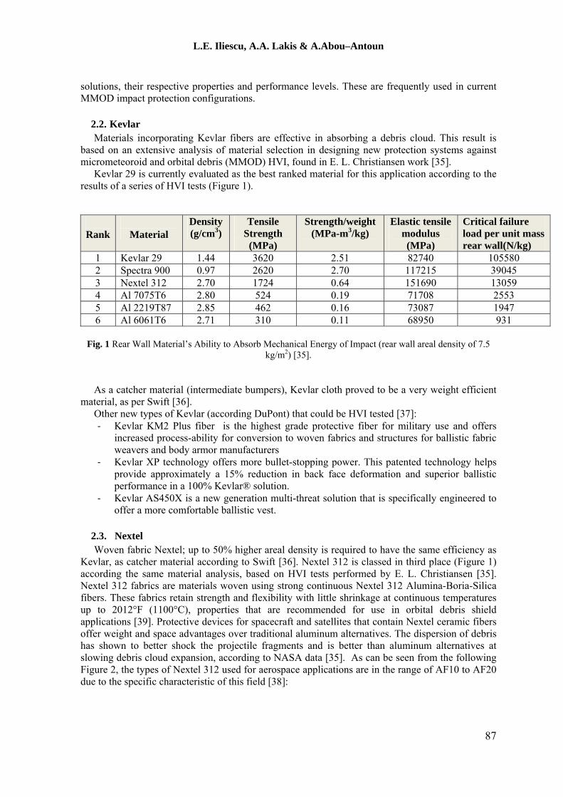
Kevlar 29 is currently evaluated as the best ranked material for this application according to the results of a series of HVI tests (Figure 1).
Rank
Material
Density (g/cm3)
Tensile Strength (MPa)
Strength/weight (MPa-m3/kg)
Elastic tensile modulus (MPa)
Critical failure load per unit mass rear wall(N/kg)
1 Kevlar 29 1.44 3620 2.51 82740 105580 2 Spectra 900 0.97 2620 2.70 117215 39045 3 Nextel 312 2.70 1724 0.64 151690 13059 4 Al 7075T6 2.80 524 0.19 71708 2553 5 Al 2219T87 2.85 462 0.16 73087 1947 6 Al 6061T6 2.71 310 0.11 68950 931
Fig. 1 Rear Wall Material’s Ability to Absorb Mechanical Energy of Impact (rear wall areal density of 7.5
kg/m2) [35].
As a catcher material (intermediate bumpers), Kevlar cloth proved to be a very weight efficient material, as per Swift [36].
Other new types of Kevlar (according DuPont) that could be HVI tested [37]: ‐ Kevlar KM2 Plus fiber is the highest grade protective fiber for military use and offers
increased process-ability for conversion to woven fabrics and structures for ballistic fabric weavers and body armor manufacturers
‐ Kevlar XP technology offers more bullet-stopping power. This patented technology helps provide approximately a 15% reduction in back face deformation and superior ballistic performance in a 100% Kevlar® solution.
‐ Kevlar AS450X is a new generation multi-threat solution that is specifically engineered to offer a more comfortable ballistic vest.
2.3. Nextel Woven fabric Nextel; up to 50% higher areal density is required to have the same efficiency as
Kevlar, as catcher material according to Swift [36]. Nextel 312 is classed in third place (Figure 1) according the same material analysis, based on HVI tests performed by E. L. Christiansen [35]. Nextel 312 fabrics are materials woven using strong continuous Nextel 312 Alumina-Boria-Silica fibers. These fabrics retain strength and flexibility with little shrinkage at continuous temperatures up to 2012°F (1100°C), properties that are recommended for use in orbital debris shield applications [39]. Protective devices for spacecraft and satellites that contain Nextel ceramic fibers offer weight and space advantages over traditional aluminum alternatives. The dispersion of debris has shown to better shock the projectile fragments and is better than aluminum alternatives at slowing debris cloud expansion, according to NASA data [35]. As can be seen from the following Figure 2, the types of Nextel 312 used for aerospace applications are in the range of AF10 to AF20 due to the specific characteristic of this field [38]:
87

L.E. Iliescu, A.A. Lakis & A.Abou–Antoun
Fig. 2 General trends for Nextel™ Woven Fabrics 312 [38].
2.4. Kapton Kapton is mentioned only due to its use in applications such as the solar array and for thermal
management. It is not suitable for MMOD HVI shield design. According to the manufacturer (DuPont), Kapton polyimide films have high performance, reliability and durability, offering a unique combination of electrical, thermal, chemical and mechanical properties that withstand extreme temperature, vibration and other demanding environments [40].
2.5. Carbon-fiber-reinforced polymer (CFRP) Plans call for extensive use of CFRP materials in the primary structures of future space
systems. These have very complex damage mechanisms however (internal delamination), and a series of HVI tests are required to analyze any proposed CFRP. An extensive study of the performance of CFRP during HVI, which shows the complexity in investigating this issue, is presented by M. Wicklein [41]. Properties of the investigated material (CFRP-Al/HC), which represent the actual satellite wall structures, are shown in Figure 3:
Fig. 3 Properties of the investigated CFRP- Al/HC by the article [41].
The article tentatively selects the best structure in terms of fiber volume, resins system, lay-up,
manufacturing process, cell size and uses 6 mm thick CFRP plates to produce a characterisation of the material. As can be seen from the following table (Figure 4) the speeds of the debris at impact are similar to those produced by the McGill small launcher that we’ve used for our tests.
88

L.E. Iliescu, A.A. Lakis & A.Abou–Antoun
Fig. 4 Planar plate impact tests conducted with CFRP [41].
There is a large variety of literature related to HVI on CFRP plates in different configurations. Selecting/proposing the best CFRP material to be future tested (HVI) can only be done after a vast literature review that will cover different disciplines and extensive experimental data.
2.5.1. Effects of adding resins As mentioned earlier, materials used for the first bumpers are usually aluminum 2 series or 6
series, however some particular cases such as the one in Hon Wan’s work [42] show that the stacking combination of carbon-fiber-reinforced polymer composite (CFRP) along with aluminum 2024 alloys significantly reduces the peak shock pressure induced by hypervelocity impact. A bumper using this combination resisted a 9 km/s impact without perforation. In addition, and in a similar way to the aluminum/CFRP laminate, aluminum/ Kevlar-fiber-reinforced polymer composites (KFRP) were tested and showed promising results. Moreover, results showed that aluminum/KFRP demonstrates the best shielding effect on resisting HVI.
It is not very common however for Kevlar or Nextel to be used as front bumper materials [42, 43]. These materials are usually used and are more efficient for intermediate bumper shields. For example, in one study [43], Nextel fabric and Kevlar fabric composed with epoxy resin was used as an intermediate bumper to protect the primary structure. The following figure presents the layout of the Columbus debris shield (Figure 5).
Fig. 5 Layout of the Columbus debris shield configuration [43]
89

L.E. Iliescu, A.A. Lakis & A.Abou–Antoun
As we can see from the above figure, the 1st BS is made of aluminum of 2.5 mm thickness, and the 2nd or intermediate BS is made of Nextel and Kevlar/Epoxy. The nature of the material used is shown in Table 1. Four layers of Nextel 312 AF-62 were used as fabric; however 18 plies of Kevlar 129 Style 812 were impregnated with Epoxy resin Brochier 914. The Nextel/Kevlar stuffing has shown to be excellent in absorbing the impulsive load of the debris cloud generated by the projectile impact on the external shield.
Table 1 Materials data for the Columbus structure
Layer Material External Bumper (WS) Al 6061-T6, 2.5 mm
Nextel 312 AF-62, 4 layers Intermediate Bumper (Stuffing) Kevlar 129 Style 812 18 plies +
Epoxy resin Brochier 914 Back Wall (BW) Al 2219-T851, 4.8 mm
2.5.2. Effects of adding reinforcers (Carbon Nanotubes, Nano-particles, self-healing agent, hardening microspheres…)
Some authors have studied the effect of adding nanomaterial reinforcers on the HVI response of these materials [44, 45]. Suman Khatiwada [44] studied the effect of Single walled carbon nanotube (SWCNT) reinforcement in Epoxy/ Ultra-High Molecular Weight Polyethylene (UHMWP) Fiber Composites on the HVI response. The study compares the HVI performance of Nano-composites against that of epoxy/UHMWPE composites without nanotubes (or simply, neat composites) and aluminum (Al) sheets with an areal density similar to both the composites. Results show that the Nano-composites and the neat composites perform better as rear walls than the Al sheets, but are less effective bumper shields. Comparatively, the two composites perform similarly to one another as rear walls and as bumper shields. For these epoxy/UHMWPE composite samples, reinforcement with 0.5 wt% of SWCNT has no noticeable effect on their HVI response. Similar results were noted for CNT/a-SiC composites studied by Maxim A. Makeev [45].
2.5.3. The use of composite as material for MMOD bumpers Two interesting reviews were done by William P. Schonberg comparing composite bumper
materials and pressure wall combinations to aluminum bumper and pressure wall combinations [3, 46]. The review studies the use of composite materials as outer bumpers, inner bumpers and pressure walls, comparing them with their aluminum counterpart while stating the advantages and disadvantages of both materials. In purpose of comparison the study chose aluminum plates thicknesses so that they have the same areal density as the corresponding composite bumper plates.
For the outer bumper, in the composite systems the bumpers were made of Kevlar 49 or Graphite/Epoxy with an aluminum pressure wall. In the aluminum systems the bumpers and pressure walls were made of aluminum. From the result of the HVI tests it appears that the composite dual wall systems do not offer an advantage when used as an outer bumper compared to an all-aluminum dual wall. For the inner bumper, the system was constructed using an aluminum outer bumper and pressure wall while varying the inner bumper by using aluminum, Spectra 900/Epoxy or Kevlar 49/Epoxy. Results show that using composite material as an inner bumper of a multi-wall system gives increased protection against HVI impact. The study extended as far as using composite materials for the pressure wall. Results show that there are three main advantages of using composite material, namely Graphite/Epoxy, as a pressure wall material. First, it eliminates the severe cracking and petaling sustained by aluminum at high speeds. Second, the ballistic performance was superior to the composites. And finally, patching a hole in composite material can easily be done by adhesive bonding.
90
L.E. Iliescu, A.A. Lakis & A.Abou–Antoun
2.5.4. Selection of optimal combination (materials, number of layer, resin or not, reinforcers …)
The information collected above was analyzed taking into consideration cost, preparation time, availability of the materials and the purposes of this study. The most optimal material combination (for the future steps of this research) to achieve a good bumper shield would be to use aluminum 2 series or 6 series for the first bumper shield, followed by a combination of Kevlar 129 or 29 and Nextel fabric with no resin and no reinforcement as an intermediate shield to catch the debris cloud. This combination should prove to be efficient for eventual HVI testing and signal detection in line with the purpose of this study.
3. HVI performed at the Shock Wave Physics laboratory of McGill University 3.1. Description of test facility
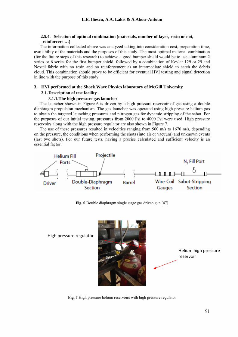
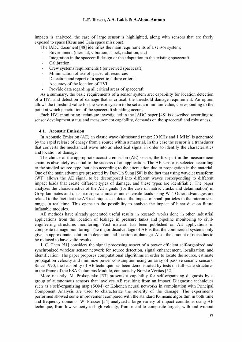
3.1.1. The high pressure gas launcher The launcher shown in Figure 6 is driven by a high pressure reservoir of gas using a double
diaphragm propulsion mechanism. The gas launcher was operated using high pressure helium gas to obtain the targeted launching pressures and nitrogen gas for dynamic stripping of the sabot. For the purposes of our initial testing, pressures from 2000 Psi to 4000 Psi were used. High pressure reservoirs along with the high pressure regulator are also shown in Figure 7.
The use of these pressures resulted in velocities ranging from 560 m/s to 1670 m/s, depending on the pressure, the conditions when performing the shots (into air or vacuum) and unknown events (last two shots). For our future tests, having a precise calculated and sufficient velocity is an essential factor.
Fig. 6 Double diaphragm single stage gas driven gun [47]
High pressure regulator
Helium high pressure reservoir
Fig. 7 High pressure helium reservoirs with high pressure regulator
91

L.E. Iliescu, A.A. Lakis & A.Abou–Antoun
3.1.2. Double diaphragm mechanism As mentioned earlier a double diaphragm mechanism was used for launching the projectile.
This mechanism provides consistency in the results. The diaphragms were circles of 1.9 cm diameter stamped out of Mylar and a brass sheet with a thickness of 0.005 in. The thickness of the diaphragms varies with different pressures.
In order to explain how this mechanism works, we first assume a final driving pressure of 2000 Psi. Although this pressure can change depending on the actual velocity required, the working mechanism remains unchanged. Note that it is not the overall pressure that drives the mechanism; rather it is the pressure difference across the diaphragms. Initially, both the high and low pressure sections are filled to half the total pressure (1000 Psi), corresponding to a pressure difference of 0 PSI across the first diaphragm and 1000 Psi across the second as shown in Figure 8 (b). The high pressure section is then filled to the final driving pressure (2000 PSI), corresponding to a pressure difference of 1000 PSI across both diaphragms. Finally, the low pressure reservoir is vented resulting in a pressure difference of 2000 PSI on the first diaphragm. The diaphragm must be able to withstand at least half of the full pressure, therefore its thickness depends on the pressure used; at higher pressures a thicker diaphragm is required.
Fig. 8 Steps for the double diaphragm mechanism [47]
3.1.3. Fabrication of the sabot Using a sabot in firing a small irregularly shaped object is a very common technique. In our
tests, the material used for the sabot is polycarbonate. Included with the sabot is a rare earth magnet NdFeB, MAGCRAFT part NSN0591, which is used to determine the velocity of the projectile. The design of the sabot and the projectile is shown in Figure 9 and 10. The sabot was stamped out of a polycarbonate sheet 4.6 mm thick using a #10 punch (McMaster-Carr part # 3424A22). It was then machined on the lathe to add grooves for the spherical projectile and to create a Bridgman type seal on the back. In addition, a slot for press fit of the rare earth magnet was machined using a mill.
92

L.E. Iliescu, A.A. Lakis & A.Abou–Antoun
Super glue was used to hold the projectile to the sabot so that it is not pulled off during the process of filling the gun with Helium.
Fig. 9 Sabot and projectile design
Fig. 10 Manufactured Sabot
The stripping mechanism of the sabot requires special attention. Two methods are currently used at the McGill testing laboratory: dynamic and mechanical. Due to the time required to perform a series of tests aimed at improving mechanical separation, we opted for the dynamic method. This method has an unwanted effect caused by a secondary impact of the sabot on the target, which adds another peak in our recorded signal. For future tests a combination of the two methods will be used to avoid this secondary impact. 3.1.4. Sabot stripping section
In order to avoid the impact of the sabot with our specimen, a separation between the sabot and the projectile was required. The mechanism used was a combination of gas dynamic and mechanical stripping. First, the gas dynamic mechanism consists of filling a section with Nitrogen (N2), which is substantially heavier than the driving gas, He. When the Projectile/Sabot enters the nitrogen section a shock wave is created that substantially slows the speed of the sabot. This sudden decrease in velocity separates the projectile from the sabot as shown in Figure 11.
Fig. 11 Nitrogen stripping section [47]
93

L.E. Iliescu, A.A. Lakis & A.Abou–Antoun
A second separation mechanism was used to deflect the sabot from its original trajectory to avoid hitting the sample and thus inducing unwanted noise in the signal. The mechanical separator did not give us the desired results and did not efficiently deflect the sabot; further work should be done to resolve this issue. 3.2. Target materials
For the initial trial testing (at McGill University on the 1st week of June), the proposed target material was Aluminum 6061-T6 (2 mm and 5 mm in thickness) and Carbon fiber/Epoxy rigid composite sheet (3.175 mm and 6.35 mm in thickness). The material choice was made in order to create at least two types of hypervelocity impact damage: crater and perforation, in two different materials and also considering other factors such as: material review, market availability, test facility availability and the timeframe.
To fit the targets into the test section of the McGill setup, the material plates were cut in squares of 11 x 11 mm. These plates were clamped between two wooden cylinders that fit tightly inside the testing section as shown in Figure 12.
Fig. 12 Test section in McGill University, Shock Wave Physics laboratory
For our future preliminary tests, the vacuum chamber could be required to generate a hypervelocity impact in a low velocity regime. However, due to the timeframe of this project and the target design requirements we are not planning to use it and, as a consequence, we will not achieve the corresponding decrease in the impact velocity. On the other hand, it was inconvenient for this stage of testing to remove this section and therefore we accommodated it in our initial test session. For future tests, the gun will most likely be fired into air on a test sample held at four points and mounted using a vibration acquisition system. This more elaborate set up should allow more precise signal analysis. 3.3. Data acquisition system
The data acquisition system used for the preliminary signals was the Ni PXI (Figure 14) coupled with three accelerometers. The accelerometers were mounted on the testing section as shown in Figure 13. One accelerometer was mounted on the sample with crazy glue to hold it in place and the other two were mounted on the outside of the testing section.
94

L.E. Iliescu, A.A. Lakis & A.Abou–Antoun
Fig. 13 Accelerometer mounted on sample
Fig. 14 NI PXI
3.3.1. Acquisition Hardware NI digitizer (PXIe-1062Q) and LabView software are used to convert the analogue signal to
digital and store the signals on a PC. The table below summarizes the main features. The NI PXIe-1062Q chassis combines a high-performance 8-slot PXI Express backplane with a high-output power supply and a structural design that has been optimized for maximum usability in a wide range of applications. The chassis’ modular design ensures a high level of maintainability, resulting in a very low mean time to repair (MTTR). The NI PXIe-1062Q chassis fully complies with the PXI-5 PXI Express Hardware Specification, offering advanced timing and synchronization features.
The key features of the NI PXIe-1062Q chassis include the following high performance instrumentation requirements:
‐ Up to 1 GB/s (single direction) per PXI Express slot dedicated bandwidth (x4 PCIe) ‐ 353.9 W available power for 0 to 55 °C ‐ 30 W per slot cooling meets increased PXI Express cooling requirements ‐ Low-jitter internal 10 MHz reference clock for PXI slots with ± 25 ppm stability ‐ Low-jitter internal 100 MHz reference clock for PXI Express slots with ± 25 ppm stability ‐ Quiet operation for 0 to 30 °C at 43.6 dBA.
3.3.2. Measurement devices used - accelerometers
As a general definition, sensors are devices that convert the physical phenomena under study (in our case, impact vibration response) into a signal that can be recognized by the data acquisition hardware. Well suited for the McGill testing session, analog sensors produce output signals that are proportional to their inputs and are also continuous in time and magnitude like the observed vibrations. The physical variable measured is the acceleration caused by the impact force generated when a projectile and sabot hit the target.
In general, accelerometers are fixed on the monitored component since the target is usually fixed. In our case, one sensor is fixed directly to the plate surface. The selection procedure was based on a determination of the required sensitivity, bandwidth and resolution needed for the accelerometers to properly collect the vibration responses. The projectile and sabot are moving at a very high speed, i.e. 1670 m/s. If the surface of the plate or structure is contaminated (in the best case with micro-cracks) due to the hyper velocity hit, this means that the system is affected. In our case, we need to have accelerometers with very high sensitivity to detect such micro-cracks. Good candidates for our application are those with sensitivity ranging from 0.1 to 10.2 mv/ (m/s2). Unfortunately, the resolution of accelerometers with high sensitivity is very poor compared to those
95

L.E. Iliescu, A.A. Lakis & A.Abou–Antoun
with low sensitivity. Resolution is defined as the lowest change in amplitude that the accelerometer can detect. As a trade-off in our case, we focused on the sensitivity instead of the resolution.
Figure 15 and Table 2 present the PCB Piezotronics accelerometers that were considered suited for this type of test.
Fig. 15 PCB Piezotronics accelerometers, model: 352C33.
Table2 PCB Accelerometer specifications
Model Sensitivity Measurement Range
Frequency Range (±5%)
Resonant Frequency
Broadband Resolution
Non-Linearity
PCB352C33 10.2 mV/(m/s2)
± 490 m/s2 0.5 to 10000Hz
≥50 kHz 0.0015 m/s2
rms ≤ 5 %
4. MMOD impact detection techniques Next, the paper presents the techniques for impact detection on spacecraft and uses as a
guideline the structure described in the document developed by the Inter-Agency Space Debris Coordination Committee (IADC) [48] elaborated in 2013, which presents a comprehensive review of technical options for detecting and characterizing of MMOD impacts. The document [48] includes the schematics of the sensor system, comparative analysis of options based on mass, volume, power, and efforts necessary in order to be integrated on a space vehicle. Information about development status, technology readiness level and the work done in the area is also included.
The necessity of an integrated sensor system in the design of a spacecraft is highly motivated by factors as:
‐ The MMOD penetration risk that is always present ‐ Location and severity of HVI ‐ The particularities of an Impact Health Monitoring System for spacecraft ‐ The wide area to be monitored ‐ The possibility of using of other sensors already integrated
In order to identify a sensor system the document starts from the measurable effects that characterize the HVI: electromagnetic or acoustic emissions, shock-induced accelerations, ejecta, secondary debris or plasma clouds or characteristics and chemical properties of HVI damage.
The effects on micron sized particle HVI are presented by Gerhard Drolshagen [49]. His paper assesses the damage of small particles in the 1–100 µm size range. Particles in this size range have generated damage on the solar cell of Hubble Space Telescope and on Charge Coupled Devices of the XMM-Newton telescope. Also, the degradation of sensors due to a large number of small
96
L.E. Iliescu, A.A. Lakis & A.Abou–Antoun
impacts is analyzed, the case of large sensor is highlighted, along with sensors that are freely exposed to space (Xeus and Gaia space missions).
The IADC document [48] identifies the main requirements of a sensor system; ‐ Environment (thermal, vibration, shock, radiation, etc) ‐ Integration in the spacecraft design or the adaptation to the existing spacecraft ‐ Calibration ‐ Crew systems requirements ( for crewed spacecraft) ‐ Minimization of use of spacecraft resources ‐ Detection and report of a specific failure criteria ‐ Accuracy of the location of HVI ‐ Provide data regarding all critical areas of spacecraft
As a summary, the basic requirements of a sensor system are: capability for location detection of a HVI and detection of damage that is critical, the threshold damage requirement. An option allows the threshold value for the sensor system to be set at a minimum value, corresponding to the point at which penetration of the spacecraft shielding occurs.
Each HVI monitoring technique investigated in the IADC paper [48] is described according to sensor development status and measurement capability, demands on the spacecraft and robustness.
4.1. Acoustic Emission In Acoustic Emission (AE) an elastic wave (ultrasound range: 20 KHz and 1 MHz) is generated
by the rapid release of energy from a source within a material. In this case the sensor is a transducer that converts the mechanical wave into an electrical signal in order to identify the characteristics and location of damage.
The choice of the appropriate acoustic emission (AE) sensor, the first part in the measurement chain, is absolutely essential to the success of an application. The AE sensor is selected according to the studied source type, but also according to the attenuation due to propagation in the material. One of the main advantages presented by Dae-Un Sung [50] is the fact that using wavelet transform (WT) allows the AE signal to be decomposed into different waves corresponding to different impact loads that create different types of damage, and these types are identifiable. The paper analyzes the characteristics of the AE signals (for the case of matrix cracks and delamination) in GrEp laminates and quasi-isotropic laminates under tensile loads using WT. Other advantages are related to the fact that the AE techniques can detect the impact of small particles in the micron size range, in real time. This opens up the possibility to analyze the impact of lunar dust on future inflatable modules.
AE methods have already generated useful results in research works done in other industrial applications from the location of leakage in pressure tanks and pipeline monitoring to civil-engineering structures monitoring. Vast material has been published on AE applications in composite damage monitoring. The major disadvantage of AE is that the commercial systems only give an approximate solution in detection and location of damage. Also, the amount of noise has to be reduced to have valid results.
J. C. Chen [51] considers the signal processing aspect of a power efficient self-organized and synchronized wireless sensor network for source detection, signal enhancement, localization, and identification. The paper proposes computational algorithms in order to locate the source, estimate propagation velocity and minimize power consumption using an array of passive seismic sensors. Since 1990, the feasibility of AE technique has been demonstrated by tests on full-scale structures in the frame of the ESA Columbus Module, contracts by Norske Veritas [52].
More recently, M. Prokopenko [53] presents a capability for self-organizing diagnosis by a group of autonomous sensors that involves AE resulting from an impact. Diagnostic techniques such as a self-organizing map (SOM) or Kohonen neural networks in combination with Principal Component Analysis are used to characterize the severity of the damage. The experiments performed showed some improvement compared with the standard K-means algorithm in both time and frequency domains. W. Prosser [54] analyzed a large variety of impact conditions using AE technique, from low-velocity to high velocity, from metal to composite targets, with and without
97
L.E. Iliescu, A.A. Lakis & A.Abou–Antoun
perforation. The paper concluded that the low and high velocity impacts could be easily distinguished using their frequency content and modal analysis. The existence of large flexural modes in the AE signals provides an indication of non- perforation of plates. There are two types of AE sensors; asymmetric sensors, which consist of a single sensing element providing high omnidirectional sensitivity (not affected by the direction from which the waves arrive) and differential sensors, which are capable of common mode rejection of unwanted components of the wave and also offer good protection against electromagnetic interference (EMI). The output of a differential sensor must be directed to a module with at least 24 dB common mode rejection. As an indication of the mass and power resource that a typical AE monitoring system will require on the spacecraft, the IADC document [48] gives the example of the ESA Columbus Module. In this case, the total mass is estimated at 3.2 kg and the power consumption at 20 W. In terms of environmental robustness, vacuum conditions are not a disturbing factor, although the noise level and temperature variations should be taken into consideration during design.
4.2. Accelerometers Accelerometers measure and characterize the mechanical shock that results in an HVI. The
shock creates in-plane and out-of plane waves. Furthermore, as Francesconi noted [55], based on Lamb wave theory and using wavelet transform analysis the wave characteristics (wave group velocity, frequency content, time between wave propagation and reflection, amplitude) can be detected, characteristics that could eventually lead to location and identification of impact damage. Due to the large availability of different forms of this type of sensor in engineering, accelerometers represent an appealing solution. A network of such sensors is used by Boeing for the orbiter Discovery to monitor impacts. This same approach is used in the new External Wireless Instrumentation System (EWIS) to monitor and analyze the behavior of a truss structure [56]. Use of accelerometers for impact detection and characterization is a branch of research that has recently been recognized by the NASA Phase 2 Small Business innovation Research (SBIR) program award for development of a miniaturized piezoielectric sensory node that will monitor impacts using an accelerometer, acoustic emission sensor or other PZT element. Details about the circuit design and other potential applications can be found elsewhere [57].
Depending on the distance to impact, point accelerometers can be tailored for near, mid and far fields with a wide range of measurement levels from 0.001 ms-2 to 2x10⁶ ms-2 and bandwidths 200-250 kHz (sensor resonance around 1 MHz). In the literature, Endevco, B&K and PCB shock sensors are used to record the shocks generated after a HVI.
Concerning the resources required for a monitoring system using accelerometers, mass and power consumption are not major factors to consider, however data handling could be a major point due to the huge amount of data that needs to be stored and analyzed to enable identification of impact characteristics. From the point of view of environmental robustness, vacuum conditions are well tolerated, but temperature variations could lead to de-calibrations of the sensor, which should not be directly exposed to the space environment.
4.3. Thermography/Imaging Technique Imaging techniques that can be used to detect HVI include: ‐ Periodic inspections at very precise time intervals, not suitable for real-time monitoring ‐ Continuous sampling, based on the principle that an HVI generates a strong heating effect
that can be detected by the appropriate sensors. ‐ A combination of these 2 methods.
In detecting (measurement) the temperature of a material some general methods are: direct contact with sensitive elements, indirect methods such as extrapolation, and methods of measuring distance.
One method consists in measuring the infrared radiation emitted by the surface which depends also on the state of the surface, its nature and its emissivity factor (which depends on the emission angle). Evaluation of the surface temperature using this method introduces a systematic error that cannot be measured, but it allows a heat map to be drawn without requiring contact.
98

L.E. Iliescu, A.A. Lakis & A.Abou–Antoun
Microwave thermography is based on detection of electromagnetic waves of thermal origin, radiated by a material. Its disadvantages: not limited to a specified well-delimited area and the electromagnetic waves carrying the information are of very low amplitude. Use of this technique in HVI thermal inspection began in 1992. The results are presented in a NASA technical report [58] in which an NDE approach together with ultrasonic volumetric imaging were used to detect and quantify delamination in a composite. P.A Howell [59] presents an in-space solution for thermal NDE using solar energy as a heat source to overcome constraints due to limited available resources. He underlined the importance of development of this type of inspection tools for future space missions.
The IADC HVI team proposed a continuous sampling method that uses the detection of thermal emissions that occur due to HVI on CFRP bumpers [48]. One result is that the temperature gradient appears to be impact energy dependent. Unfortunately, the high frame rate necessary to monitor such a short event made it difficult to implement this technique. Other papers suggest a combination with other methods in order to have more valid results. A wide range of thermal detectors have been developed but these sensors are not yet qualified for space. The resources needed are considerable from the point of view of mass, volume, power or data handling. Specialized solutions are needed in order to be operable in a space environment.
4.4. Calorimetric Impact Detection Calorimetric impact detection Is based on the principle that most energy of the impact particle is
transferred to the target as heat and a temperature sensor can be used to measure the variance. The monitoring of HVI will be done through a detector that uses the heat conversion efficiency (ratio between measurable calorimetric heat and kinetic energy of the impacting particle). T. Poppe [60] presents a solution for in-space measurement of impacting MMOD. A particularity of the solution is the fact that the detector surface is covered by a conductor network that is severed at the moment of impact.
As a second option for simulating thermal processes during an impact, K.Bunte [61] has another solution that uses calorimetric measurements of the deposed thermal energy, which correlates with the particle’s kinetic energy (based on velocity measured by an optical device - laser). Experiments are performed to prove this method. Based on factors such as the properties of the materials used as energy absorbers (metals with high thermal conductivity) and the element size (heat capacitance is proportional to thickness) the calorimetric sensitivity can be adapted to meet the needs of the mission. Research is currently underway on the development of a flight model incorporating this solution. M. Kobush [62] considers a type of sensor that uses a 16x16 array of miniaturized calorimeters to detect the heat generation and as consequence the energy increase caused by the impact of a micron sized iron particle. In the IADC document [48] the calorimetric sensor (AIDA) measurement capability is determined through a series of tests (functional, performance and sensitivity, environmental and HVI) in air or in a vacuum using laser pulse heating and gold absorbers. Using the calorimetric method, the impact energy can be measured and therefore the location of the impact of a specific design can be estimated. This data, in combination with that gained using other methods could provide information about particle mass, diameter or velocity.
The environmental tests showed that thermal loads can lead to variations in the sensor signals. Radiation and plasma, on the other hand, are not expected to influence to this type of sensor. Other type of factors, such as vibrations or electromagnetic interference, can be addressed through design. Resource demands are; approximately 10 W of power and less than 2 kg of mass.
4.5. Optical Fibre Sensors Fibre optic (glass fibre) sensors as is described by Grattan K. T. [63] are generally composed
of: ‐ a light leading core to transmit the signal, mainly quartz ‐ a coating that transmits light at a low refractive index (causes reflection, the light remains
in the core), usually quartz
99
L.E. Iliescu, A.A. Lakis & A.Abou–Antoun
‐ a thin film of varnish (2 to 5 µm) for protection ‐ a plastic coating for protection against mechanical damage ( 50 to 500 µm)
Prosser W.H [64] identify two classes of fiber optic sensors for discrete strains and temperature measurement:
‐ cavity based designs, which use an interferometric cavity in the fiber (extrinsic and intrinsic/fiber Fabry-Perot interferometer-EFPI and IFPI or FFPI) and do not allow for multiplexing capability in a single fiber;
‐ grating based designs, which use a photo- or heat-induced periodicity in the fiber core refractive index to create a sensor whose reflected or transmitted wavelength is a function of this periodicity and allow multiplexing using gratings of different wavelength (using wavelength division multiplexing –WDM or optical frequency domain reflectometry OFDR principles ). Factors limiting the number of sensors in a single fiber include the bandwidth limitations of the source and the range over which the physical parameter of interest is being measured [63, 64, 65]
Chapter 3 of W. Staszewski’s book [66] describes load monitoring technologies that use optical fibre sensors (Bragg grating sensors), and discusses various technological aspects that need to be addressed for effective structural usage monitoring and assessment. These include: specifications and reliability of sensors, fibre coating technology and an optical signal processor, together with a description of the nature of Bragg grating sensors. Prosser [64] considers that fiber optic sensors are leading candidate technology that meets the requirement of minimal weight and also provide a huge advantage in their ability to measure many different structural parameters of interest, offer immunity to electromagnetic interference (EMI), and have the ability to operate over a very large range of temperatures and environments. Wolfgang E. [67] presents an FBG sensor network based on multiplexed Bragg grating technology that was developed for a space application on board the X-38 experimental re-entry vehicle. During launch and re-entry, 12 locally distributed Bragg gratings (eight for strain, and four for temperature measurements) are used to measure the condition of a structural element.
López-Higuera [68] illustrates the potential of optical fiber sensors (OFS) used in structural health monitoring (SHM) applications. A number of cases where OFS for SHM systems have already been demonstrated and checked with real in-field validations are mentioned in applications including renewable energy, transportation, civil engineering, and oil and gas. K. Schroeder [69] presents the design and provides examples of a fibre Bragg grating sensor system that has been installed and successfully operated in a horizontal-axis wind turbine since 2004. Reinhart W. [70] presents systems that are based on potential low-cost components such as draw-tower FBG arrays that use optimized photosensitive fibers with sensor-specific coatings and spectral high-resolution polychromators for sensor interrogation. Performance and reliability of the sensor systems have been demonstrated by tests in the areas such as; electric power generators, aircraft and spacecraft structures, and in geotechnical monitoring applications. Smart Fibers Ltd. [71] demonstrates the measurement capabilities of such sensors and the fact that the FBG allow continuous and autonomous measurements. Single mode fibres, each of which can contain several thousand sensors, have a transmission rate up to 1 Gbit/s.
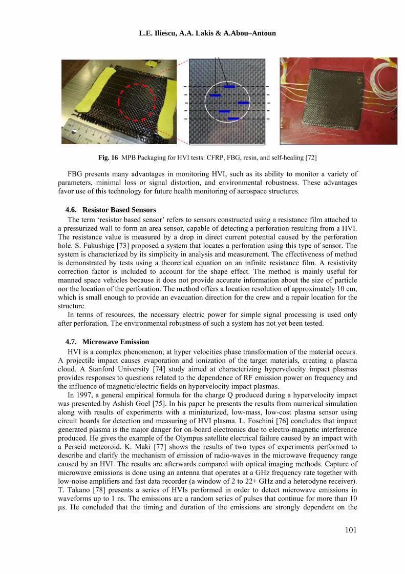
The measurement range, resolution and sample rate depend on the system itself and can provide for strain measurements ranging up to 80.000 μm/m for a single strain sensor and a temperature measurement range from cryogenic to 300°C. From point of view of possible application of fiber optic sensors for monitoring HVI in space, the problem is the thermally loaded parts of the spacecraft during re-entry (approx. 3% of surface). The fiber optic sensors can withstand a variety of factors as chemicals, radiation and high temperature. Also, they will not react to interference with electromagnetic fields. MPB in collaboration with McGill University [72] have carried out HVI tests on self-healing CFRP laminates and monitored the effect using fiber sensors, Figure 16. The study shows the effectiveness of the fiber sensors in monitoring the debris and their effects after the impact.
100
L.E. Iliescu, A.A. Lakis & A.Abou–Antoun
Fig. 16 MPB Packaging for HVI tests: CFRP, FBG, resin, and self-healing [72]
FBG presents many advantages in monitoring HVI, such as its ability to monitor a variety of parameters, minimal loss or signal distortion, and environmental robustness. These advantages favor use of this technology for future health monitoring of aerospace structures.
4.6. Resistor Based Sensors The term ‘resistor based sensor’ refers to sensors constructed using a resistance film attached to
a pressurized wall to form an area sensor, capable of detecting a perforation resulting from a HVI. The resistance value is measured by a drop in direct current potential caused by the perforation hole. S. Fukushige [73] proposed a system that locates a perforation using this type of sensor. The system is characterized by its simplicity in analysis and measurement. The effectiveness of method is demonstrated by tests using a theoretical equation on an infinite resistance film. A resistivity correction factor is included to account for the shape effect. The method is mainly useful for manned space vehicles because it does not provide accurate information about the size of particle nor the location of the perforation. The method offers a location resolution of approximately 10 cm, which is small enough to provide an evacuation direction for the crew and a repair location for the structure.
In terms of resources, the necessary electric power for simple signal processing is used only after perforation. The environmental robustness of such a system has not yet been tested.
4.7. Microwave Emission HVI is a complex phenomenon; at hyper velocities phase transformation of the material occurs.
A projectile impact causes evaporation and ionization of the target materials, creating a plasma cloud. A Stanford University [74] study aimed at characterizing hypervelocity impact plasmas provides responses to questions related to the dependence of RF emission power on frequency and the influence of magnetic/electric fields on hypervelocity impact plasmas.
In 1997, a general empirical formula for the charge Q produced during a hypervelocity impact was presented by Ashish Goel [75]. In his paper he presents the results from numerical simulation along with results of experiments with a miniaturized, low-mass, low-cost plasma sensor using circuit boards for detection and measuring of HVI plasma. L. Foschini [76] concludes that impact generated plasma is the major danger for on-board electronics due to electro-magnetic interference produced. He gives the example of the Olympus satellite electrical failure caused by an impact with a Perseid meteoroid. K. Maki [77] shows the results of two types of experiments performed to describe and clarify the mechanism of emission of radio-waves in the microwave frequency range caused by an HVI. The results are afterwards compared with optical imaging methods. Capture of microwave emissions is done using an antenna that operates at a GHz frequency rate together with low-noise amplifiers and fast data recorder (a window of 2 to 22+ GHz and a heterodyne receiver). T. Takano [78] presents a series of HVIs performed in order to detect microwave emissions in waveforms up to 1 ns. The emissions are a random series of pulses that continue for more than 10 µs. He concluded that the timing and duration of the emissions are strongly dependent on the
101

L.E. Iliescu, A.A. Lakis & A.Abou–Antoun
material and thickness of target. Large emission delays were observed in the case of a perforated target.
The development of this type of sensor for use as an integrated spacecraft sensor requires a lot of effort due to a limited understanding of the theoretical process and the difficulty in testing and calibrating the sensor.
4.8. Surface Inspection Cameras Another HVI detection technique currently used on the NASA Space Shuttle is the Orbiter
Boom Sensor System (OBSS), used to scan the leading edges of the wings or the nose cap. Surface inspection cameras take a series of digital still images of the spacecraft surface over a period of time and transmit these images to Earth for analysis (onboard processors could significantly increase the spacecraft resources needed to use this approach).
H. Hirayama [79] presents an onboard surface inspection system that consists of a small high-resolution charge-coupled device (CCD) camera, data handling and communication subsystems that detect impacts on the surface created by micron-sized debris impact. A high resolution image is transmitted to a ground station for further analysis. The paper concluded that the size of the impacting debris can be estimated, but the velocity of the impacting object is difficult to determine. B. Kennedy [80] proposes a small, agile and capable six-legged walking robot that has been built at the Jet Propulsion Laboratory to perform dexterous small-scale assembly, inspection and maintenance. The robot uses an external sensor system composed of a set of black and white cameras. The images taken by these cameras are combined in software to create a 3D model of the world around LEMUR for autonomous operation.
4.9. Carbon Nano-Tube Sensors W.H Prosser [64] presents this new type of sensor that can be integrated into future onboard
spacecraft structural health management SHM systems to detect HVI. Due to the high strength-to-weight ratio of carbon nanotubes combined with quantum transport characteristics, this type of sensor is ideal for future multifunctional structural materials. The Nano-tubes can function as strain sensors (through transfer of the circuit to a flexible substrate) and as magnetic field sensors (through injection of spin-polarized electrons).
4.10. Solar Panel based Space Debris Impact Detectors A solar panel based space debris impact detector (SOLID) is a large-area impact detector
presented by W. Bauer [81] that can be used to gather information on MMOD distributions, which is necessary for model validation. The photo-voltaic cells of the solar panels are used as detection surfaces. An insulation layer behind the solar cells is equipped with two layers of copper lines that form a detection grid. Information including damage detection, damage diameter and impacting particle size can be obtained. This method is used exclusively in evaluation of MMOD fluxes and not to monitor HVI on a spacecraft surface.
4.11. Smart Skin Concept A future approach is presented by BAE Systems [82]. The “smart skin” concept is based on
embedding tens of thousands of micro-sensors that can accurately sense wind speed, temperature, physical strain and movement. The presented system will have all the characteristics of a health monitoring system such as real time sensing, increased efficiency and improved safety. The system will use tiny sensors or “motes” and complete computing packets that are smaller than grains of rice or even as small as dust particles at less than 1 square mm (could be applied like spray paint). The smart skin contains its own power source and appropriate data analysis capabilities.
4.12. Advantages/Disadvantages: Accelerometers and Fiber Optic Sensors Based on this review and as identified in the IADC document, accelerometers represent the
currently available first choice as sensors to be used in a hypervelocity impact health monitoring
102

L.E. Iliescu, A.A. Lakis & A.Abou–Antoun
system. Fiber optic sensors, which offer excellent accuracy, coverage, environmental robustness and simplicity, represent one of the top choices for future monitoring systems. Sensor systems that use accelerometers detect and measure vibrations produced by HVI-induced shocks on spacecraft structures. They can assess impact locations and criticality and have the ability to manage signals (high frequency content). However, they use considerable resources of the spacecraft. Integrated impact detection systems that use fiber optic sensors (available and widely used in aerospace structures) are currently under development. The advantages offered make this a promising technology for monitoring HVI in spite of the difficulty in integrating fiber optics into the spacecraft structure.
5. Test Results Six satisfactory recorded tests (5 preliminary signals plus the test “0” signal, which is recorded
from outside the vacuum chamber) were performed on our aluminum and carbon fiber samples using the gas launcher at different gas pressures, thus different projectile velocities. The test results are shown in Table 3. In addition, a series of tests was done to verify the mechanical stripper proposed by McGill. The data includes cases where similar preparation for the firing was done, but the shots were not performed or were prematurely triggered due to different factors such as coils triggering, diaphragm penetration, mechanical strippers or other unknown factors that will be analyzed later. Special attention should be given to all these factors in order to be able to perform well-controlled shots.
Table 3 Test Summary
Sample Projectile Pressure (PSI)
Velocity (m/s)
Vacuum Others
Preparatory Test
No sample Sabot alone 4000 1638 Yes -
Preparatory Test
CF 1/8’’ Full 2 mm sphere
4000 1573 Yes N2+Mech. Separator, No penetration No Acquisition
Preparatory Test (test 0)
CF 1/8’’ Full 2 mm sphere
4000 1573 No N2 Separator, No penetration Acquisition (on the vacuum chamber)
Test 1 CF 1/8’’ Full 3.2 mm sphere
4000 1570 No N2 Separator, Penetration Acquisition
Test 2 CF 1/8’’ Full 3.2 mm sphere
2500 880 No N2 Separator, No Penetration Acquisition
Test 3 Al 2mm Full 3.2 mm sphere
4000 570 No N2 Separator, Penetration Acquisition
Test 4 Al 5mm Full 3.2 mm sphere
4000 540 No N2 Separator, No Penetration Acquisition
103
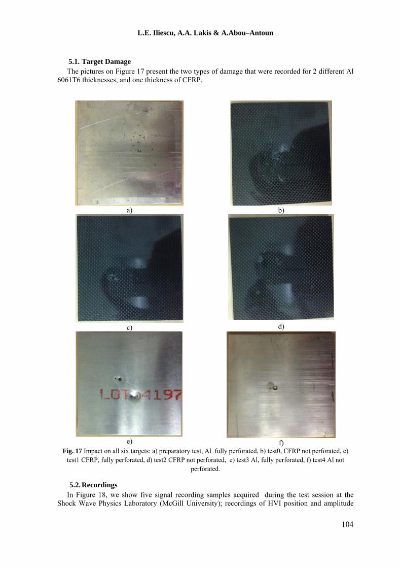
L.E. Iliescu, A.A. Lakis & A.Abou–Antoun
5.1. Target Damage The pictures on Figure 17 present the two types of damage that were recorded for 2 different Al
6061T6 thicknesses, and one thickness of CFRP.
a)
b)
c)
d)
e)
f)
Fig. 17 Impact on all six targets: a) preparatory test, Al fully perforated, b) test0, CFRP not perforated, c) test1 CFRP, fully perforated, d) test2 CFRP not perforated, e) test3 Al, fully perforated, f) test4 Al not
perforated.
5.2. Recordings In Figure 18, we show five signal recording samples acquired during the test session at the
Shock Wave Physics Laboratory (McGill University); recordings of HVI position and amplitude
104

L.E. Iliescu, A.A. Lakis & A.Abou–Antoun
(with damage characteristics, penetration or not penetration). The time of impact could not be determined.
a)
b)
c)
d)
e)
Fig. 18 Recorded signals for five tests (for test0 the accelerometer was mounted on the vacuum chamber), y axis represent accelerations (m/s2)
MPB Communications Inc. [72] previously also performed a series of HVI tests on CFRP modified targets that included self-healing materials and used fiber sensors and fast acquisition (2MHz) to record the impact. The signals were analyzed with the same TF software. The self-healing materials were composed of microcapsules containing combinations of a 5-ethylidene-2-norbornene (5E2N) and dicyclopentadiene (DCPD) monomers of 100-300 μm diameter and ruthenium Grubbs' as a catalyst. Using vacuum centrifuge techniques these combinations were blended with a resin epoxy and single-walled carbon nanotubes (SWNTs). The samples also
105

L.E. Iliescu, A.A. Lakis & A.Abou–Antoun
survived thermal shock (20 cycles, -196 ̊to +60 ̊C) and were tested for compatibility with a vacuum. HVI tests were performed on 12cm x 12cm x 2 mm thick samples that contained a lay out of resin mixed with microcapsules and a catalyst and a lay out of the fiber sensor. The resin was cured in an autoclave (40 ̊C, 40 psi for 12 hours). Different samples were impacted by projectiles with velocities between 1 to 8 Km/s, the velocities given by standard instruments were validated by measurement of the time between triggering and the effect on FBG.
The signal results recorded on a CFRP 828-CHCNT target by the four FBG sensors are shown in Figure 19.
Fig. 19 FBG sensors at 2MHz recording the HVI [72].
The frequency distribution (FFT) of signals using FBG sensors is shown in Figure 20.
a) b)
Fig. 20 FFT analysis: a) CFRP 828-SHCNT sample, b) summary for all samples [72].
106

L.E. Iliescu, A.A. Lakis & A.Abou–Antoun
6. Next Steps Future steps should be taken in essential directions that are closely related; further HVI tests and
time-frequency analysis (TF) of the signal recordings.
6.1. HVI Tests The first essential direction is continuing to perform HVI tests, similar to the primary step using
the same gun, with the purpose of obtaining better precision in velocity and sabot separation. Precise velocity control is an important factor in creating the required type of damage. Sabot separation is very important in order to eliminate the secondary impact on the target. For distant future work however, a secondary impact on the target could be a plus in characterizing the response of materials or bringing new information necessary for creation of smart material. An example is a material that uses elements for self-healing.
A further step will be to perform new hypervelocity tests at velocities up to 4.5 to 5 km/s, which are considered intermediate velocities for MMOD impacts, at the same Shock Wave Laboratory at McGill University. These can be done using a new 2-stage light gas gun currently under construction. The use of TF signal analysis for HVI tests performed in the low-velocity regime would generate new information for characterizing impact damage. Note that for this step a phase transformation of the material will occur. A final step in the experimental phase would be to perform HVI tests at speeds relatively close to MMOD impact.
The implosion gun in the same laboratory can perform HVI impact tests at 8 km/s. Preparation of these tests and TF analysis of the data will involve a large amount of work. It is therefore suggested that these types of tests be performed further in the future. At this time the implosion gun is scheduled to fire only two times in a Canadian Space Agency project that involves impact tests on a CFRP material similar to that used in the Canadarm.
6.2. TF Signal Analysis The other critical direction for future work is in the area of TF signal analysis. This work will
involve a considerable amount of time to analyze recorded signals so that the best method can be found that allows identification of the types of damage on different types of materials. A first step in this direction will be to perform a TF analysis [83-85] yielding a compact representation of machine condition which includes important effects associated with non-stationarity. The TF-Analysis software developed by the research group is ideally suited for analysis and reduction of multi-sensor spectro-temporal steady and transient data. Signals caused by debris impact are highly transient and short-lived. Time-frequency analysis methods incorporated in TF-Analysis will be used to efficiently extract the primary features of the impact signals.
Figure 21 presents an example of the use of TF analysis software for analysis of one of the tests done at the Shock Wave Physics Laboratory (McGill University).
107

L.E. Iliescu, A.A. Lakis & A.Abou–Antoun
a)
b)
Fig. 21 An example of Wavelet transform (WT) signal analysis using our software (decomposition level, 9 and 11).
The above two images present an example of TF analysis performed on the first part of the last signal recorded. It seems that there is a cluster (waves) of frequencies that is constant and is repeating at some time intervals. This could be a cluster of symmetrical S waves that don’t present a dispersive behavior, have un-changed shape and their frequency components travelled at the same speed. The figure could represent the arrival of the first wave group from the impact point and the arrival of the same wave group reflected from the boundary, but this is a very preliminary interpretation and further, deeper analysis must be done. The TF analysis will continue for all sections of signals recorded in order to precisely identify the moment of the signal and also minimize the number of measurement points so that the different in-plane IP or out-of-plane OP accelerations can be recognized. The wavelet transform WT analysis is able to identify both the frequency content and propagation velocity. This information could be important for identifying the type of damage; with or without perforation. The same TF analysis software will be used to analyze the test signal recordings previously obtained by MPB. However, as can be seen in Figure
108

L.E. Iliescu, A.A. Lakis & A.Abou–Antoun
19 above, an initial transformation of signals from deformations to accelerations is needed. This can be done using Matlab software and will be presented in the next work.
As a result of this research work, a new capability for automation of the process and the creation of a library of different types of materials used in space together with damage identification can be achieved.
7. Conclusions The work performed at the Shock Physics laboratory of McGill University, the tests performed
and the signal recordings obtained represent an essential first step in applying TF analysis software in a system capable of real-time detection and analysis of the effects of MMOD impacts. The short literature review described the most frequently used materials for these types of applications, the best positions these materials should be mounted in a future shield design based on their characteristics and the difficulties involved in selecting the best material. For the case of composite materials, the choice of the matrix is essential in providing the desired protection. For example, metallic or ceramic matrices presented good results in shattering the projectile.
Kevlar fiber materials, due to their unique characteristics, perform very well in catching the fragments of a debris cloud. Tests were performed at low impact velocity, up to 1.6 km/s. This velocity is not representative of MMOD velocities but is sufficient in offering the signal recordings necessary for further investigation. In addition to the test results, new knowledge was gained relative to manipulating the gun, specific gun capabilities/characteristics and methods for manufacturing different elements such as the sabot (a very complex and essential element) or the mechanical stripper. We also learned about unexpected problems that could arise in this type of test and the necessary equipment and costs involved in performing further HVI tests, especially at the higher velocities essential for characterizing MMOD damage.
The first preliminary recordings that indicate the presence and effect of an impact on targets are very significant to begin to understand the damage mechanism and the potential to gather more information using further T-F analysis. Presently, observations/interpretation of the signal recordings lead us to important conclusions that can be applied during future HVI tests, such as the potential advantages of a second time-recording element and the necessity of preparation of signals in order to identify the time of the HVI impact.
As a general conclusion, the tests performed were successful, the signal recordings are valid. This section of work can be considered the cornerstone of our future work in this area.
References 1. Shannon R., and Eric L., ‘Hypervelocity impact testing of advanced materials and structures for
micrometeoroid and orbital debris shielding’, NASA Johnson Space Center, US, 2012. 2. Burton G., and Cour-P., ‘Hypervelocity impact in metals, glass and composites’, NASA, 1987. 3. Schonberg W.P., ‘Protecting spacecraft against orbital debris impact damage using composite materials’,
Composites: Part A, 31 (2000) 869–878. 4. Keisuke F., Motokazu A., Noriyuki K., Eiichi Y. and Yasuhiro T., ‘Impact perforation behaviour of
CFRPs using high-velocity steel sphere’, International Journal of Impact Engineering, 27 (2002), 497–508.
5. Nagao Y., Kibe S., Daigo K., Francesconi A. and Pavarin D., ‘Hypervelocity impact studies simulating debris collisions on composites material’, Proceedings of the forth European Conference on Space Debris, Darmstadt, Germany, (April 2005), 18-20.
6. Daniel B., Alfredo R, Sérgio F.M, Francisco C.L. and Maurício V., ‘Ballistic impact simulation of an armour-piercing projectile on hybrid ceramic/fiber reinforced composite armours’, International Journal of Impact Engineering, 43 (2012), 63-77.
7. Makoto T., Yoko M, Yasuhiro A, Ryuta N.A. and Susumu S., ‘Development of a lightweight space debris shield using high strength fibers’, International Journal of Impact Engineering, 26 (2001), 761-772.
8. Tanaka M., and Moritaka Y., ‘Single bumper shields based on Vectran fibers’, Advances in Space Research, 34 (2004), 1076–1079.
9. Yasuhiro A, Ryuta N. and Makoto T., ‘Development of bumper shield using low density materials’, International Journal of Impact Engineering, 26 (2001), 13-19.
109

L.E. Iliescu, A.A. Lakis & A.Abou–Antoun
10. Wei Z. G., Sandstrom R. and Miyazaki S., ‘Shape memory materials and hybrid composites for smart systems. Part II, Shape-memory hybrid composites’, Journal of materials science, 33 (1998), 3763 — 3783.
11. Robinson J. H. and Nolen A. M., ‘An investigation of metal matrix composites as shields for hypervelocity orbital debris impacts’ , Int. J. Impact Eng., 17 (1995), 685-696.
12. Katz S., Grossman E., Gouzman I., Murat M., Wiesel E. and Wagner H.D., ‘Response of composite materials to hypervelocity impact’, International Journal of Impact Engineering, 35 (2008), 1606–1611.
13. Clegg R.A., White D.M., Riedel W. and Harwick W., ‘Hypervelocity impact damage prediction in composites: Part I-material model and characterisation’, International Journal of Impact Engineering, 33 (2006), 190–200.
14. Riedel W., Nahme H., White D.M. and Clegg R.A., ‘Hypervelocity impact damage prediction in composites: Part II - experimental investigations and simulations’, International Journal of Impact Engineering, 33 (2006), 670–680.
15. Martin R, Frank S, Roberto D, Moreno F. and Michel L., ‘Fragmentation of hypervelocity aluminum projectiles on fabrics’, Acta Astronautica, 76 (2012), 42–50.
16. Bryan A. Cheeseman, Travis A. and Bogetti B., ‘Ballistic impact into fabric and compliant composite laminates’ Composite Structures, 61 (2003), 161–173.
17. Destefanis R., Amerio E., Briccarello M., Belluco M., Faraud M., Tracino E. and Lobascio C., ‘Space environment characterization of Kevlar: good for bullets, debris and radiation too’ ISMSE -11, 11th International Symposium on Materials in a Space Environment, Aix-en-Provence, France September 2009. 15-18,
18. Roberto D., and Moreno F., ‘Testing of advanced materials for high resistance debris shielding’, Int. J. Impact Engng, 20 (1997), 209-222.
19. Taylor E. A., Herbert M. K., Vaughanh B. A. M, and. Mcdonnell J. A. M., ‘Hypervelocity impact on carbon fibre reinforced plastic/aluminum honeycomb: comparison with Whipple bumper shields’, International Journal of Impact Engineering , 23 (1999), 883-893.
20. Emma T. A., Jonathan P., Glanville, Richard A., and Robert G., ‘Hypervelocity impact on spacecraft honeycomb: hydro code simulation and damage laws’, International Journal of Impact Engineering, 29 (2003), 691–702.
21. Francesconi A., Pavarin D., Bettella A., Giacomuzzo C., Faraud M., Destefanis R., Lambert M., and Angrilli F., ‘Generation of transient vibrations on aluminum honeycomb sandwich panels subjected to hypervelocity impacts’, International Journal of Impact Engineering, 35 (2008), 1503–1509.
22. IADC WG3 ‘IADC Protection manual’ IADC-04-03, Version 4.0, April 12, 2011. 23. Grujicic M., Pandurangan B., Zhao C.L., Biggers S.B., Morgan D.R., ‘Hypervelocity impact resistance
of reinforced carbon–carbon/carbon–foam thermal protection systems’,Applied Surface Science.,252 (2006), 5035-5050.
24. Ryan S., and Christiansen E.L., ‘Honeycomb vs. foam: evaluating potential upgrades to ISS module shielding’ IAC-09.A6.3.11.
25. Ryan S., Ordonez E., and Christiansen E. L., Lear D. M., ‘Hypervelocity impact performance of open cell foam core sandwich panel structures’, NASA 2010.
26. Zhang X., Jia G., and Huang H., ‘Numerical Investigation of aluminum foam shield based on fractal theory and node-separation FEM’, Chinese Journal of Aeronautics, 24 (2011), 734-740.
27. Bin J., Feng Li., Hai P. G., and Bao Jun Pang., ‘Performance of different metal-foam stuffed Whipple shield against hypervelocity impact of space debris’, Key Engineering Materials, 122 (2011), 488-489.
28. Eric L., Justin H., ‘Mesh double-bumper shield: A low-weight alternative for spacecraft meteoroid and orbital debris protection’, International Journal of Impact Engineering, 14 (1993), 169-180.
29. Higashide M., Tanaka M., Akahoshia Y., Harada S., and Tohyama F., ‘Hypervelocity impact tests against metallic meshes’, International Journal of Impact Engineering, 33 (2006), 335–342.
30. Dezhi Z, Guoqin C, Gaohui W, Pengchao K, and Wei D.,‘Hypervelocity impact damage to Ti–6Al–4V meshes reinforced Al–6Mg alloy matrix composites’, Materials Science and Engineering, A500 (2009), 43-46.
31. Guo Q., Sun D.L., Han X.L., Yang W.S., Jiang L.T., and Wu G.H., ‘Damage behaviour of Al matrix composite reinforced with Ti–6Al–4V meshes under the hypervelocity impact’, Materials Science and Engineering, A 535 (2012), 136– 143.
32. Merzhievsky L., ‘Crater formation in a plastic target under hypervelocity impact’, Int. J. Impact Engng, 20 (1997), 557-568.
33. Mudric T., Giacomuzzo C., Galvanetto U., Francesconi A., Zaccariotto M., Grande A. M., and Landro L. Di., ‘Impact tests and simulations for multifunctional materials’ ECCM15 – 15th European conference on composite materials, Venice, Italy, (June 2012), 24-28.
110

L.E. Iliescu, A.A. Lakis & A.Abou–Antoun
34. Stephen J., Kalista Jr., and Thomas C., ‘Self-Healing of poly (Ethylene-co-Methacrylic Acid) copolymers following ballistic puncture’ Proceedings of the First International Conference on Self-Healing Materials, Noordwijkaan Zee, Netherlands (April 2007),218-20.
35. Eric L. Christiansen ‘TP−2003-210788. Meteoroid/debris shielding’ NASA (August 2003). 36. Swift, H. F., ‘Hypervelocity Impact Mechanics, Impact Dynamics” John Wiley and Sons (1982). 37. DuPont,http://www.dupont.com/products-and-services/fabrics-fibers-nonwovens
/fibers/brands/kevlar.html. 38. DuPont,http://www.dupont.com/products-and-services/fabrics-fibers-nonwovens/fibers/press-
releases/next-generation-of-innovations-with-Kevlar.html. 39. 3MNextelCeramicTextilesandComposites,
http://www.3m.com/market/industrial/ceramics/materials/fabric_312.html. 40. Du Pont USA, http://www2.dupont.com/Kapton/en_US/. 41. Wicklein M., Ryan S., White D.M., and Clegg R.A., ‘Hypervelocity impact on CFRP: testing, material
modelling, and numerical simulation’, International Journal of Impact Engineering, 35 (2008), 1861–1869.
42. Hong W., Shuxin B., Shun L., Jianjun M., Shicao Z., and Zhenfei S., ‘Shielding performances of the designed hybrid laminates impacted by hypervelocity flyer”, Materials and Design, 52 (2013), 422–428.
43. Christiansen E.L., Crews-NASA Johnson, Williamsen J.E., Robinson J.H., Nolen-NASA Marshall A.M., ‘3M Nextel Ceramic Fabric Offers Space Age Protection’, Intl. Journal of Impact Engineering,, Vol. 17.
44. Suman K., Carlos A. A., and Enrique V. B., ‘Hypervelocity Impact Experiments on Epoxy/Ultra-High Molecular Weight Polyethylene Fiber Composites Reinforced with Single-Walled Carbon Nanotubes’, Procedia Engineering, 58 (2013), 4 -10.
45. Maxim A. Makeev, and Deepak S., ‘Molecular dynamics simulations of hypersonic velocity impact protection properties of CNT/a-SiC composites’ Composites Science and Technology, 68 (2008), 2451–2455.
46. William P. S., ‘Protecting Earth-orbiting spacecraft against micro-meteoroid/orbital debris impact damage using composite structural systems and materials: An overview’Advances in Space Research, 45 (2010), 709–720.
47. Anthony D., ‘The combustion of bulk metals in a high-speed oxidizing flow’, Master’s thesis, McGill University Montreal, Quebec (2014) 4-15.
48. IADC WG3, Sensor systems to detect impacts on spacecraft, IADC-08-03, Version 2.1, April 2013. 49. Gerhard D., ‘Impact effects from small size meteoroids and space debris’, Advances in Space Research,
41 (2008), 1123–1131. 50. Dae S, Hun-G K, and Hang-Sun H., ‘Monitoring of impact damages in composite laminates using
wavelet transform.’, Composites Pats B, 33 (2002), 35-43. 51. Chen J.C., Y.K., Hudson R.E., Tung T.L., Reed C.W., and Chen D., ‘Source localization of a wideband
source using a randomly distributed beam forming sensor array’, International Journal of High Performance Computing Applications (2002).
52. Norske V., ‘In-Orbit Non-Destructive Testing –Extension’ ESA / ESTEC Contract No. 8433/89/NL/PP (SC), DNV Report 92-3207 Rev. 2, 1992.
53. Mikhail P., Peter W., Andrew S., Vadim G., Nigel H., and Don P., ‘On Self-organising Diagnostics in Impact Sensing Networks’, Knowledge-Based Intelligent Information and Engineering Systems Lecture Notes in Computer Science, 3684 (2005), 170-178.
54. William H. P., Michael R. G., and Donald H. H., ‘Acoustic emission signals in thin plates produced by impact damage’ , Journal of Acoustic Emission,17 ( 1999), 29-36.
55. Bettella A., Francesconi A., Pavarin D., Giacomuzzo C., and Angrilli F., ‘Application of Wavelet Transform to analyze acceleration signals generated by HVI on thin aluminum plates and all-aluminum honeycomb sandwich panels’, International Journal of Impact Engineering, 35 (2008), 1427–1434.
56. Boeing,http://www.boeingtravel.com/assets/pdf/defense- space/space/spacestation/components/docs/EWIS.pdf ).
57. Kevin D. C., Jonathan S., ‘Low-power electronics for distributed impact detection and piezoelectric sensor applications’, Aerospace Conference, 2007 ,IEEE.
58. Smith B. T., ‘Rapid detection and quantification of impact damage in composite structures’, NASA-CR-190367, 1992.
59. Howell. P.A., Winfree W.P., and Cramer, K.E., ‘Infrared on-orbit inspection of shuttle orbiter reinforced carbon-carbon using solar heating’ SPIE Optics and Photonics, 31 Jul-4 Aug 2005, San Diego, CA, USA.
60. Poppe T., Sdunnus H., and Rex D., ‘AIDA - Advanced impact detector assembly for the on-orbit measurement of small impacting debris particles and meteoroids’, Adv. Space Res., 17(1996), 133-136.
111

L.E. Iliescu, A.A. Lakis & A.Abou–Antoun
61. Bunte K. D., Kobusch M., Hollandt J., Illemann J., Jager F., Glaser M., and Sarge S., ‘AIDA - An Advanced Impact Detector Assembly’ IAC-03-IAA.5. (2003), P.02.
62. Kobush M., Jager F., Bunte K. D., Fichna T., and Kessler E., ‘Calorimetric Energy Detector for Space Debris’, IAC-06-B6.3.9.
63. Grattan, K.T.V., et al., Optical Fiber Sensor Technology, (1999), Vol. 3. 64. Prosser, W.H., ‘Development of structural health management technology for aerospace vehicles’,
JANNAF 39th Combustion/27th Airbreathing Propulsion/21st Propulsion Systems Harzards/3rd Modeling and Simulation Joint Subcommittee Meeting; 1-5 Sep. 2003.
65. Kashima, S., and Ozaki, T., ‘Structural health monitoring using FBG sensor in space environment, Proc’. SPIE (2001), Vol. 4332, p.78-87.
66. Boller W.J. S., and Tomlinson G.R., ‘Health Monitoring of Aerospace Structures’ John Wiley & Sons Ltd, 2004.
67. Wolfgang E., Ines L., Reinhardt W., Arnd R., and Roland G., ‘The paper Fibre optic sensor network for spacecraft health monitoring’, E. Meas. Sci. Technol., 12 (2001), 974–980.
68. José H., Luis R. C., Antonio Q. I., and Adolfo C., ‘Fiber optic sensors in structural health monitoring’ Journal of light wave technology,29 (2011).
69. Kerstin S., Wolfgang E., Jorg A., Elfrun L., and Gerhard L., ‘A fibre Bragg grating sensor system monitors operational load in a wind turbine rotor blade’, Meas. Sci. Technol., 17 (2006), 1167–1172.
70. Reinhardt W, Wofgang E., ‘Potential low-cost optical fiber Bragg-grating sensor systems for structural health monitoring and examples of their application’, SPIE 4920, Advanced Sensor Systems and Applications, (9 September 2002).
71. Smart Fibres Ltd., UK, http://www.smartfibres.com. 72. Aissa B., Tagziria K., Jamroz W., Haddad E., Asgar-Khan M., Hoa S. V., Loiseau J., Verreault J., and
Higgins A., ‘Monitoring with Fiber sensors and Self-Healing of CFRP Laminates Exposed to Hypervelocity Small Pellets Simulating Space Debris’, 12th International Symposium on Materials in the Space Environment (IMSE-12, September 2012), 24-28.
73. Fukushige S., Akahoshi Y., Koura T., and Harada S., ‘Development of perforation hole detection system for space debris impact’, International Journal of Impact Engineering, 33 (2006), 273–284.
74. Stanford University, Space Environment and Satellite Systems, http://sess.stanford.edu/hvip. 75. Ashish G., Paul M. Tarantino, David S. Lauben, Sigrid Close, ‘Design and testing of miniaturized
plasma sensor for space plasma diagnostics’ ,Spacecraft Charging Technology Conference, 2014 – 181. 76. Foschini L., ‘The meteoroid hazard for space navigation’ ,Planetary Science: Second Italian meeting.
Eds A. Manara and E. Dotto. Alenia Spazio, Torino (1999), p. 131. 77. Maki K., Takano T., Fujiwara A., and Yamori A., ‘Radio-wave emission due to hypervelocity impacts in
relation to optical observation and projectile speed’, Advances in Space Research, 34 (2004), 1085-1089. 78. Takano, T., Murotani, Y., Toda, T., Fujiwara, A., Hasegawa, S., and Yamori, S. ‘Microwave emission
experiment with hypervelocity impacts and applications of its results’, Proceedings of the Third European Conference on Space Debris, March 2001, 19 - 21.
79. Hirayama H., Hanada T., and Yasaka T., ‘In situ debris measurements in MEO/HEO using onboard spacecraft surface inspection system’ , Advances in Space Research, 34 (2004), 951-956.
80. Brett K, Hrand A., Yang Ch., Michael G., Gregory H., Terry H., Lee M., Colin M., Amy M., Jennifer K., ‘LEMUR: Legged Excursion Mechanical Utility Rover’, Autonomous Robots, 11(2001), 201–205.
81. Waldemar B., Romberg O., Wiedemann C., Drolshagen G., Vorsmann P., ‘Development of in-situ space debris detector’Advances in Space Research., 54 (2014), 1858-1869.
82. BAE Systems, http://www.baesystems.com/article/BAES_175799/aircraft-set-to-become-more-human-as-engineers-develop-smart-skins-which-can-detect-injury.
83. Oulmane A., Lakis A.A. and Mureithi N., ‘A Method for Analyzing Rotating Machinery Faults using Time-Frequency Application’. International Journal of Condition Monitoring and Diagnostic Engineering Management, 16 (2013), 21-34.
84. Safizadeh, M.S., Lakis, A.A., and Thomas, M., ‘Time-Frequency and Their Application to Machinery Fault Detection’, International Journal of Condition Monitoring and Diagnostic Engineering Management, 4(2000), 10-27.
85. Mahvash, A., Lakis A.A., ‘Independent Component Analysis as Applied to Vibration Source Separation and Fault Diagnosis’, Journal of vibration and control, online: August 2014, DQI: 10.117/107756314544349.
112
L.E. Iliescu, A.A. Lakis & A.Abou–Antoun
113
Appendix The test requires a lot of preparation, safety measures and the purchase of many components. Necessary (not an exhaustive list, a detailed list will be presented later on):
High pressure Helium gas Tanks (6000 PSI) and Nitrogen gas High pressure Gas regulator Polycarbonate sheets for the Sabot Mylar and Brass sheets for the diaphragms together with the sealing gaskets Rare earth magnet Target materials and projectile spheres Tooling for the required manufacturing processes Additional materials for the target support Special materials needed in order to measure and record the speed as: oscilloscope and
high speed camera with stroboscope (if considered necessary) Miscellaneous
Preparations: Placement of the gun and additional equipment in the laboratory ( MPB or École Poly) Manufacturing of the Sabot and eventually design of the mechanical stripper Design and manufacturing of the targets and sample support
Safety measures: Safety glasses Ear protections People cannot be in the room while firing Ventilation systems Gloves