hygienic design cylinder series hy - smc pneumatics · hygienic design cylinder series external...
TRANSCRIPT

Series HY�Hygienic Design Cylinder
SeriesExternal seal
material
Body
material
Plug bolt
Plug bolt
Optional
parts∗Mounting
brackets∗20 25 32 40 50 63 80 100
Bore size
NBR,FKM Aluminum
HYB
HYQ
HYC
HYG
FootFlange
Single clevisDouble clevis(ø32 to ø63)
FootFlange
(ø32 to ø100)
∗ Optional parts and mounting brackets must be ordered separately. Refer to pages 885 to 889.
Page
854
858
867
873
ISO standard typeSeries HYC
Basic typeSeries HYQ
With guideSeries HYG
Series HYB
������ ������� �� ��� �������� ��� ���� � ���
851
External coverRod endHead end
HY�
CJ5CG5
C�M�
Individual-X�
D-�
-X�
Technicaldata

Scraper
Flat, grooveless configuration
Eliminates the auto switch groove and the holes for cushion needle holes, etc.
Plug bolt(Optional)
Plug bolt(Optional)
External cover(Optional)
Conventional
Cushion needle
Grease for food (NSF-H1 certified) is available.
External seal material: Choice of NBR or FKM
Mounting section: Conforms to ISO/VDMA standard. (Series HYQ, HYC)
Five times increase in service life compared to conventional model (SMC ratio)
Water-proof examination result (Reference data)
1 2 3 4 5
Standard cylinder
Hygienic Design Cylinder (HYB, HYQ, HYC, HYG)
Comparison with conventional model: Approx. 5 times.Comparison with conventional model: Approx. 5 times.Water resistance improvement cylinder
Cushion needle (PAT.)
HYB
HYC
HYQ
Not applicable for use in a "food zone". For details, refer to Specific Product Precautions (Page 890).
Washing in water/Temperature: 30°C, Flow rate: 160 cc/min
A water resistant cylinder cA water resistant cylinder c
852
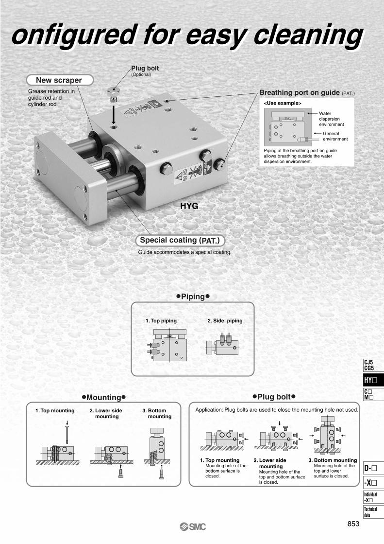
New scraper
Special coating (PAT.)
Guide accommodates a special coating.
Grease retention in guide rod and cylinder rod
Plug bolt(Optional)
Breathing port on guide (PAT.)
Piping at the breathing port on guide allows breathing outside the water dispersion environment.
<Use example>
Mounting
1. Top mounting 2. Lower side
mounting
3. Bottom
mounting
Plug bolt
Piping
1. Top mountingMounting hole of thebottom surface isclosed.
2. Lower side
mountingMounting hole of the top and bottom surfaceis closed.
3. Bottom mountingMounting hole of thetop and lower surface is closed.
Application: Plug bolts are used to close the mounting hole not used.
1. Top piping 2. Side piping
Waterdispersionenvironment
Generalenvironment
HYG
onfigured for easy cleaningonfigured for easy cleaning
853
HY�
CJ5CG5
C�M�
Individual-X�
D-�
-X�
Technicaldata

HYB
HYDBWith auto switch
20
20
50
50
With auto switch(Built-in magnet)
H7BAL
R
R
F
F
< Mounting bracket > Foot and flange (Rod end)
< Option parts > Plug bolt
Please place an order for above mentioned parts separately, please refer to pages 885 to 889 for details.
Applicable Auto Switches/Refer to pages 1306 and 1307 for detailed auto switch specifications.
854
ø20, ø25, ø32, ø40, ø50, ø63, ø80, ø100Series HYB
Hygienic Design CylinderRound Type
How to Order
Bore size
20
25
32
40
50
63
80
100
20 mm25 mm32 mm40 mm50 mm63 mm80 mm
100 mm
Port thread type
M threadRc
NPTG
ø20, ø25
ø32 to ø100
Nil
TN
TF
Sealant material
R
H
NBRExternal FKM Note)
Note) External seal material: Rod scraper, tube gasket, and rod seal are made from FKM. Cylinder stroke
Refer to the next page for the standard stroke.
Grease
Nil
F
Standard grease (for non-food)Grease for food
Note) Select grease for food for use in a water dispersion environment or when washing a product with water.(Water resistance is insufficient with standard grease.)
Auto switch
NilWithout auto switch(Built-in magnet)
Refer to table below for selection of applicable auto switch.
Number of auto switches
Nil
S
n
2 pcs.1 pc.
“n” pcs.
SpecialfunctionType
Electricalentry
Grommet
Indicatorlight
Wiring(Output)
2-wire
Load voltage
DC ø20 to ø63 ø80, ø100
Lead wire length (m)∗
3(L)
5(Z)
Relay,PLC
Applicableload
∗ Lead wire length symbols 3 m………… L (Example) H7BAL5 m………… Z (Example) H7BAZ
• Refer to pages 1328 and 1329 for detailed specifications about the auto switch with pre-wired connector.
H7BA G5BA
Auto switch model
12 V24 VYes
Water resistanceimprovement
product(2-color display)
Solid state
switch
Pre-wiredconnector
∗ Auto switches marked with a “�” symbol are produced upon receipt of orders.

Theoretical Output
Mass
Standard Stroke
20
25 to 100
25, 50, 75, 100, 125, 150, 200
25, 50, 75, 100, 125, 150, 200, 250, 300
Bore size (mm) Standard stroke (mm)
∗ Intermediate strokes of 1 mm each can be produced. (The spacer is not used.)
Stroke (mm)
Unit: kg
Bore size (mm) 25
0.15
0.20
0.26
0.50
0.88
1.21
2.01
3.52
Without auto switch
20
25
32
40
50
63
80
100
50
0.17
0.22
0.29
0.55
0.95
1.29
2.13
3.68
75
0.18
0.24
0.32
0.59
1.02
1.38
2.24
3.84
100
0.20
0.27
0.35
0.64
1.09
1.47
2.35
3.99
125
0.22
0.29
0.38
0.68
1.15
1.55
2.47
4.15
150
0.24
0.31
0.41
0.73
1.22
1.64
2.58
4.31
175
0.26
0.34
0.44
0.78
1.29
1.72
2.69
4.47
200
0.27
0.36
0.47
0.82
1.35
1.81
2.81
4.63
250
—
0.40
0.53
0.91
1.49
1.98
3.03
4.95
300
—
0.45
0.59
1.01
1.62
2.15
3.26
5.27
Stroke (mm)
Unit: kg
Bore size (mm) 25
0.15
0.20
0.28
0.51
0.90
1.23
2.04
3.55
With auto switch (Built-in magnet)
20
25
32
40
50
63
80
100
50
0.17
0.22
0.31
0.56
0.97
1.32
2.16
3.71
75
0.19
0.25
0.33
0.61
1.03
1.40
2.27
3.87
100
0.21
0.27
0.36
0.65
1.10
1.49
2.38
4.03
125
0.22
0.29
0.39
0.70
1.17
1.58
2.50
4.19
150
0.24
0.32
0.42
0.74
1.23
1.66
2.61
4.35
175
0.26
0.34
0.45
0.79
1.30
1.75
2.72
4.51
200
0.28
0.36
0.48
0.83
1.37
1.83
2.84
4.67
250
—
0.41
0.54
0.93
1.50
2.00
3.06
4.98
300
—
0.46
0.60
1.02
1.64
2.17
3.29
5.30
Bore size (mm)
Operatingdirection
Operating pressure (MPa)
Unit: N
20
25
32
40
50
63
80
100
OUT
IN
OUT
IN
OUT
IN
OUT
IN
OUT
IN
OUT
IN
OUT
IN
OUT
IN
0.3
94.2
79.2
147
124
241
207
378
318
588
495
936
840
1510
1360
2360
2150
0.5
157
132
246
206
402
346
630
530
980
825
1560
1400
2520
2270
3930
3580
0.7
220
185
344
288
563
484
882
742
1370
1160
2180
1960
3520
3180
5500
5010
855
Series HYBHygienic Design CylinderRound Type
Specifications
Bore size (mm) 25 32 40 63 80 10020 50
Action
Fluid
Minimum operating pressure
Maximum operating pressure
Proof pressure
Lubrication
Piston speed
Cushion
Stroke length tolerance
Piston rod material
Ambient and operating fluid
temperature
Double acting, Single rod
Air
0.15 MPa
1.0 MPa
1.5 MPa
Without auto switch 0°C to 70°C
With auto switch 0°C to 60°C
Not required
50 to 500 mm/s (With pressure at 1.0 MPa) Note)
Rubber bumper
Stainless steel 304 / Hard chrome plated
0.2 MPa 0.07 MPa
+1.4 0 mm
Note) Use a cylinder below the allowable kinetic energy. Refer to page 856 for the allowable kinetic energy.
HY�
CJ5CG5
C�M�
Individual-X�
D-�
-X�
Technicaldata

Series HYB
Maximum drive speed (V mm/s)Lo
ad m
ass
(kg)
1
10
100
100
ø40
ø32
ø25
ø20
ø100
ø50
ø63
ø80
W
• A case where the center of gravity of the load rests 50 mm from the rod end.
W
50 mm
Allowable Load at Rod End
Stroke (mm)
Allo
wab
le lo
ad a
t rod
end
(N
)
25
20
15
10
5
0
ø20, ø25, ø32, ø40
1000 200 300
HYB40
HYB32
HYB25
HYB20
Stroke (mm)
Allo
wab
le lo
ad a
t rod
end
(N
)
160
140
120
100
80
60
40
20
0
ø50, ø63, ø80, ø100
1000 200 300
HYB100
HYB80
HYB50, 63
Allowable Kinetic Energy
(Supply pressure: at P = 0.5 MPa)
856

NB
S + Stroke
ø20, 25
21
A
4 x JKA
NA
øD
(øE
1)
K (F1)
H
ZZ + Stroke
øI
GB
F2
øE
2 0 -0
.05
4 x J
2 x PGA
B±0.1
Bore size(mm)
20
25
32
40
50
63
80
100
P
Nil
M5 x 0.8M5 x 0.8Rc 1/8Rc 1/8Rc 1/4Rc 1/4Rc 3/8Rc 1/2
TF
——
G 1/8G 1/8G 1/4G 1/4G 3/8G 1/2
TN
——
NPT 1/8NPT 1/8NPT 1/4NPT 1/4NPT 3/8NPT 1/2
R
3333——————
S ZZ
69 69 71 78 90 90108108
81 81 83 95107107131131
NA
30 30
35.544 55 69 80
100
NB
24 29
35.544 55 69 80
100
K
5 5 6
6.58 8
9.511.5
KA
6 8101316162227
C±0.1
øR
C±0
.1
B±0
.1
Bore size(mm) Port: M5, Rc, NPT Port: G
A B C
M4 x 0.7 depth 8M5 x 0.8 depth 10M6 x 1.0 depth 12
M8 x 1.25 depth 13M10 x 1.5 depth 15M10 x 1.5 depth 15M16 x 2.0 depth 21M20 x 2.5 depth 27
14 16.520 26 32 38 50 60
18.518.520 26 32 38 50 60
D
810121620202530
E1
1818202632323742
E2
1214182530324050
F1
33333333
F2
22222233
121314142020
111014121717
GA
1313
GB
1010101012121616
H
1010101515152020
I
26 31 38 47 58 72 89110
J
M4 x 0.7 depth 7M5 x 0.8 depth 7.5M5 x 0.8 depth 8
M6 x 1.0 depth 12M8 x 1.25 depth 16M10 x 1.5 depth 16M10 x 1.5 depth 22
M12 x 1.75 depth 22
20
25
32
40
50
63
80
100
(mm)
857
Series HYBHygienic Design CylinderRound Type
Dimensions
HY�B20 to 100
HY�
CJ5CG5
C�M�
Individual-X�
D-�
-X�
Technicaldata

HYQB
HYDQBWith auto switch
20
20
50
50 F6B
R
R
F
F
M
M
< Mounting bracket > Foot, flange, single clevis, double clevis, and clevis pin
< Option parts > External cover
Please place an order for above mentioned parts separately, please refer to pages 885 to 889 for details.
Type
Solid
state
switch
Electricalentry Wiring (Output)
Load voltage
DCAuto switch model
Lead wire length (m)∗
0.5(Nil)
3(L)
5(Z)
Applicable load
Applicable Auto Switches/Refer to page 1312 for detailed auto switch specifications.
∗ Lead wire length symbols 0.5 m…………Nil (Example) F6B3 m………… L (Example) F6BL5 m………… Z (Example) F6BZ
• Refer to pages 1328 and 1329 for detailed specifications about the auto switch with pre-wired connector.∗ Auto switch is shipped not assembled with the cylinder.
—
IC circuitYesGrommet
3-wire (NPN)
2-wire
3-wire (PNP)
Pre-wiredconnector
∗ Auto switches marked with a “�” symbol are produced upon receipt of orders.
Relay,PLC
5 V12 V
12 V
24 V
F6N
F6P
F6B
Indi
cato
rlig
ht
How to Order
858
ø20, ø25, ø32, ø40, ø50, ø63Series HYQ
Hygienic Design CylinderBasic Type
With auto switch(Built-in magnet and switch rail)
Bore size
20
25
32
40
50
63
20 mm25 mm32 mm40 mm50 mm63 mm
Port thread type
M threadRc
NPTG
ø20, ø25
ø32 to ø63
Nil
TN
TF
Sealant material
R
H
NBRExternal FKM Note)
Note) External seal material: Rod scraper, tube gasket, and rod seal are made from FKM.
Grease
Nil
F
Standard grease (for non-food)Grease for food
Style of rod end
Nil
M
Female threadMale thread
Auto switch
Nil Without auto switch
Cylinder strokeRefer to the next page for the standard stroke.
Refer to table below for selection of applicable auto switch.
Number of auto switches
Nil
S
n
2 pcs.1 pc.
“n” pcs.
Note) Select grease for food for use in a water dispersion environment or when washing a product with water.(Water resistance is insufficient with standard grease.)

859
Series HYQHygienic Design CylinderBasic Type
Action
Fluid
Minimum operating pressure
Maximum operating pressure
Proof pressure
Lubrication
Piston speed
Cushion
Stroke length tolerance
Piston rod material
Ambient and operating fluid
temperature
Double acting, Single rodAir
1.0 MPa1.5 MPa
Without auto switch 0 to 70°CWith auto switch 0 to 60°C
Not required50 to 500 mm/s (With pressure at 1.0 MPa) Note)
Rubber bumper
Stainless steel 304 / Hard chrome plated
Bore size (mm) 25 32 40 6320 50
Bore size (mm)
Operatingdirection
Operating pressure (MPa)
20
25
32
40
50
63
INOUTIN
OUTIN
OUTIN
OUTIN
OUTIN
OUT
0.3 79.2 94.2124 147 207 241 318 378 495 588 840 936
0.5 132 157 206 246 346 402 530 630 825 98014001560
0.7 185 220 288 344 484 563 742 8821160137019602180
Unit: N
Theoretical Output
0.2 MPa 0.15 MPa
+1.4 0 mm
20
25
32
40
50
63
Stroke (mm)Unit: kg
Unit: kg
Unit: kg
Unit: kg
5Bore size
(mm)
Mass
0.160.240.430.63——
100.170.260.450.661.111.59
150.180.270.480.691.201.70
200.190.290.500.721.301.82
250.200.300.520.761.391.94
300.220.320.550.791.482.06
350.230.340.570.821.572.18
400.240.350.600.851.672.30
450.250.370.620.891.762.41
500.260.390.650.921.852.53
75——
0.771.082.323.12
100——
0.891.252.783.72
Without auto switch / Female thread type
20
25
32
40
50
63
Stroke (mm)
5Bore size
(mm)
0.160.250.450.66——
100.180.270.480.701.281.68
150.190.280.500.731.371.80
200.200.300.520.761.461.92
250.210.320.550.791.552.04
300.220.330.570.831.652.15
350.230.350.600.861.742.27
400.240.360.620.891.832.39
450.250.380.650.921.932.51
500.270.400.670.962.022.63
75——
0.791.122.483.22
100——
0.911.282.953.81
Without auto switch / Male thread type
20
25
32
40
50
63
Stroke (mm)
5Bore size
(mm)
0.210.300.540.77——
100.220.320.560.811.301.86
150.230.330.890.841.401.98
200.240.350.610.871.492.10
250.260.370.640.901.592.22
300.270.390.660.941.682.34
350.280.400.690.971.782.46
400.290.420.721.001.872.58
450.310.440.741.031.972.70
500.320.460.771.072.062.82
75——
0.901.232.533.42
100——
1.021.393.014.02
With auto switch (Built-in magnet and switch rail) / Female thread type
20
25
32
40
50
63
Stroke (mm)
5Bore size
(mm)
0.210.310.560.81——
100.220.330.590.841.471.96
150.240.350.610.881.572.08
200.250.360.640.911.662.20
250.260.380.660.941.762.31
300.270.400.690.971.852.43
350.290.420.711.011.942.55
400.300.430.741.042.042.67
450.310.450.771.072.132.79
500.320.470.791.102.232.91
75——
0.921.272.703.51
100——
1.051.433.174.11
With auto switch (Built-in magnet and switch rail) / Male thread type
20
25
32
40
50
63
5, 10, 15, 20, 25, 30, 35, 40, 45, 505, 10, 15, 20, 25, 30, 35, 40, 45, 505, 10, 15, 20, 25, 30, 35, 40, 45, 50, 75, 1005, 10, 15, 20, 25, 30, 35, 40, 45, 50, 75, 10010, 15, 20, 25, 30, 35, 40, 45, 50, 75, 10010, 15, 20, 25, 30, 35, 40, 45, 50, 75, 100
Standard Stroke
Bore size (mm) Standard stroke (mm)
∗ Intermediate strokes of 1 mm each can be produced. (The spacer is not used.)
Note) Use a cylinder below the allowable kinetic energy. Refer to page 860 for the allowable kinetic energy.
Specifications
HY�
CJ5CG5
C�M�
Individual-X�
D-�
-X�
Technicaldata

Series HYQ
W
50mm
Allowable Kinetic Energy
Stroke (mm)
Allo
wab
le lo
ad a
t rod
end
(N
)
40
35
30
25
20
15
10
5
00 10 20 30 40 50 60 70 80 90 100
ø50, ø63
ø20ø25
ø40
ø32
Maximum drive speed (V mm/s)Lo
ad m
ass
(kg)
(Supply pressure: at P = 0.5 MPa)
1
10
100
100
ø20
ø25
ø32
ø50
ø40
ø63
• The above graph shows a case that the center of gravity of the load rests 50 mm from the rod end.
Allowable Load at Rod End
860
W

(Auto switch D-F6�)
!1 u y o !4 e !2 !0 r !5 !3
t q i w
!6
!8 !7
!9 @0 @1
Component Parts
No. Description
Rod cover
Head cover
Cylinder tube
Piston
Piston rod
Bushing
Bushing retainer
Hexagon socket head cap screw
Rod seal
Piston seal
Rod scraper
Bumper A
Bumper B
Tube gasket
Wearing
Rod end nut
Material
Aluminum alloy
Aluminum alloy
Aluminum alloy
Aluminum alloy
Stainless steel
Resin
Aluminum alloy
Stainless steel
NBR
NBR
NBR
Resin
Resin
NBR
Resin
Stainless steel
Qty.
1
1
1
1
1
1
1
4
1
1
1
1
1
2
1
1
Anodic oxide film
Anodic oxide film
Anodic oxide film
Chromated
Hard chromium plated
Chromated
(FKM can be selected.)
(FKM can be selected.)
(FKM can be selected.)
(Only rod end male thread)
Note
1
2
3
4
5
6
7
8
9
10
11
12
13
14
15
16
No. Description
Magnet
Magnet holder
Switch rail base
Hexagon bolt
Switch rail
Material
—
Aluminum alloy
Stainless steel
Stainless steel
Stainless steel
Qty.
1
1
2
2
1
(Only built-in magnet)
(Only built-in magnet) Chromated
(Only built-in magnet)
(Only built-in magnet)
(Only built-in magnet)
Note
17
18
19
20
21
Bore size
20
25
Part no.
HYQB20�-PS
HYQB25�-PS
Set contents
Set of nos. above o, !0 and !4
Symbol
Place the seal material symbol in �.
∗ External seal: Rod seal and the tube gasket are made from FKM.∗ Seal kit includes o, !0 and !4. Order the seal kit based on each bore size.∗ Since the seal kit does not include a grease pack, order it separately.
Grease for food part no.: GR-H-010 (10 g)Standard grease part no.: GR-S-010 (10 g)
R
H
MaterialNBR
External FKM∗
Replacement Parts: Seal Kit
861
Series HYQHygienic Design CylinderBasic Type
Construction: ø20, ø25
Rod end male thread
Basic type
Built-in magnet
HY�
CJ5CG5
C�M�
Individual-X�
D-�
-X�
Technicaldata

!1 u y o !4 e !2 !0 r !5 !3
t q i w
!6
!8 !7
!9 @0 @1
!2 !3
Set of nos. above o, !0 and !4
Component Parts
No. Description
Rod cover
Head cover
Cylinder tube
Piston
Piston rod
Bushing
Bushing retainer
Hexagon socket head cap screw
Rod seal
Piston seal
Rod scraper
Bumper A
Bumper B
Tube gasket
Wearing
Rod end nut
Magnet
Material
Aluminum alloy
Aluminum alloy
Aluminum alloy
Aluminum alloy
Stainless steel
Resin
Aluminum alloy
Stainless steel
NBR
NBR
NBR
Resin
Resin
NBR
Resin
Stainless steel
—
Qty.
1
1
1
1
1
1
1
8
1
1
1
1
1
2
1
1
2
Anodic oxide film
Anodic oxide film
Anodic oxide film
Chromated
Hard chromium plated
Chromated
(FKM can be selected.)
(FKM can be selected.)
(Only ø63 is commonto the bumper A.)
(FKM can be selected.)
(Only rod end male thread)
(Only built-in magnet)
Note
1
2
3
4
5
6
7
8
9
10
11
12
13
14
15
16
17
No. Description
Magnet holder
Switch rail base
Hexagon bolt
Switch rail
Material
Aluminum alloy
Stainless steel
Stainless steel
Stainless steel
Qty.
1
2
2
1
(Only built-in magnet) Chromated
(Only built-in magnet)
(Only built-in magnet)
(Only built-in magnet)
Note
18
19
20
21
Bore size
32
40
50
63
Part no.
HYQB32�-PS
HYQB40�-PS
HYQB50�-PS
HYQB63�-PS
Set contents
Place the seal material symbol in �.
Replacement Parts: Seal Kit
Symbol
∗ External seal: Rod seal and the tube gasket are made from FKM.∗ Seal kit includes o, !0 and !4. Order the seal kit based on each bore size.∗ Since the seal kit does not include a grease pack, order it separately.
Grease for food part no.: GR-H-010 (10 g)Standard grease part no.: GR-S-010 (10 g)
R
H
MaterialNBR
External FKM∗
862
Series HYQ
Construction: ø32 to ø63
Basic type
Rod end male thread ø63
Built-in magnet
(Auto switch D-F6�)
H1
A1 + Stroke
L1
C1
X K
KA RK R
F
øD
L
Q
øI
Rod end male thread
Width across flats B1
Width across flats KA
MM
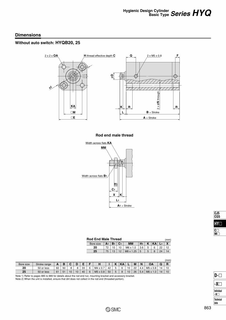
Dimensions
Without auto switch: HYQB20, 25
A + Stroke
B + Stroke
2 x
øN
thro
ugh
�E
�M
2 x M5 x 0.8H thread effective depth C2 x 2 x OA
Bore size A
6061
B
5051
C
810
D
810
E
3340
F
66
I
4250
K
55
KA
68
L
1010
M
2226
N
4.45.4
Q
1414
R
1010
OA
M5 x 0.8M6 x 1.0
H
M4 x 0.7M5 x 0.8
20
25
Stroke range50 or less50 or less
Bore size A1
7275
B1
1013
C1
1012
H1
3.65
K
55
KA
68
L1
2224
X
1214
MM
M6 x 1.0M8 x 1.25
20
25
Rod End Male Thread (mm)
(mm)
Note 1) Refer to pages 885 to 889 for details about the rod end nut, mounting bracket and accessory bracket.Note 2) When the unit is installed, ensure that dirt does not collect in the rod end (threaded portion).
863
Series HYQHygienic Design CylinderBasic Type
HY�
CJ5CG5
C�M�
Individual-X�
D-�
-X�
Technicaldata

[SB]
[29]
[SA]
[24]
[29]
10
11.5
H1
A1 + Stroke
L1
C1
X K
RK R
F
øD
L
Q
MM
KA
øI
Series HYQ
864
With auto switch: HYDQB20, 25
Rod end male thread
Dimensions
A + Stroke
B + Stroke
2 x
øN th
roug
h[Width across flats 3]
(Auto switch D-F6�)
2 x M5 x 0.8
�E
�M
H thread effective depth C2 x 2 x OA
[≅ 3
]
[≅ 2
5]
Width across flats B1
Width across flats KA
Bore size A
7071
B
6061
C
810
D
810
E
3340
F
66
I
4250
K
55
KA
68
L
1010
M
2226
N
4.45.4
Q
1414
R
1010
SA
6.56.5
SB
10.511
OA
M5 x 0.8M6 x 1.0
H
M4 x 0.7M5 x 0.8
20
25
Stroke range50 or less50 or less
Bore size A1
8285
B1
1013
C1
1012
H1
3.65
K
55
KA
68
L1
2224
X
1214
MM
M6 x 1.0M8 x 1.25
20
25
Rod End Male Thread
Note 1) The [ ] value denotes dimensions with the auto switch D-F6� mounted, which is dedicated to the Hygienic Design Cylinder. Note 2) Refer to pages 885 to 889 for details about the rod end nut, mounting bracket and accessory bracket.Note 3) When the unit is installed, ensure that dirt does not collect in the rod end (threaded portion).
(mm)
(mm)

H1
KX
C1
L1
W
W
K
FQ
øD
L
øI
KA
MM
865
Series HYQHygienic Design CylinderBasic Type
Without auto switch: HYQB32 to 63
Rod end male thread
Dimensions
A1 + Stroke
A + Stroke
B + Stroke
�E
�M
Width across flats B1
Width across flats KA
H thread effective depth C
4 x øN through2 x 4 x OA effective depth R 2 x P (Rc, NPT, G)
Bore size A
72 77.590.591
B
61 65.576.577
C
12131518
D
12162020
E
49.557.569 84
F
8.5 8.510.510.5
I
62 71 88102
K
6 6.58 8
KA
10131616
L
11121414
M
32.538 46.556.5
N
5.45.46.86.8
P
1/81/81/41/4
Q
13.516 20 21
R
16161616
W
4244
OA
M6 x 1.0M6 x 1.0
M8 x 1.25M8 x 1.25
H
M6 x 1.0M8 x 1.25M10 x 1.5
M12 x 1.75
32
40
50
63
Stroke range100 or less100 or less100 or less100 or less
Bore size A1
94 101.5122.5123
B1
17192424
C1
20 22 29.529.5
H1
6 71010
K
6 6.58 8
KA
10131616
L1
33364646
X
22243232
MM
M10 x 1.25M12 x 1.25M16 x 1.5M16 x 1.5
32
40
50
63
Rod End Male Thread (mm)
(mm)
Note 1) Refer to pages 885 to 889 for details about the rod end nut, mounting bracket and accessory bracket.Note 2) When the unit is installed, ensure that dirt does not collect in the rod end (threaded portion).
HY�
CJ5CG5
C�M�
Individual-X�
D-�
-X�
Technicaldata

10
H1
KX
C1
L1
øI
KA
MM
[SB][SA]
W
W
K
FQ
øD
L
Bore size A
87 92.5105.5106
B
76 80.591.592
C
12131518
D
12162020
E
49.557.569 84
F
8.5 8.510.510.5
I
62 71 88102
K
6 6.58 8
KA
10131616
L
11121414
M
32.538 46.556.5
N
5.45.46.86.8
P
1/81/81/41/4
Q
13.516 20 21
R
16161616
SA
8.510.510.59
SB
16161718
W
4244
OA
M6 x 1.0M6 x 1.0
M8 x 1.25M8 x 1.25
H
M6 x 1.0M8 x 1.25M10 x 1.5
M12 x 1.75
32
40
50
63
Stroke range100 or less100 or less100 or less100 or less
Bore size A1
109 116.5137.5138
B1
17192424
C1
20 22 29.529.5
H1
6 71010
K
6 6.58 8
KA
10131616
L1
33364646
X
22243232
MM
M10 x 1.25M12 x 1.25M16 x 1.5M16 x 1.5
32
40
50
63
Rod End Male Thread
Note 1) The [ ] value denotes dimensions with the auto switch D-F6� mounted, which is dedicated to the Hygienic Design Cylinder.Note 2) Refer to pages 885 to 889 for details about the rod end nut, mounting bracket and accessory bracket.Note 3) When the unit is installed, ensure that dirt does not collect in the rod end (threaded portion).
(mm)
(mm)
866
Series HYQ
With auto switch: HYDQB32 to 63
Rod end male thread
Dimensions
[24]
[29]
11.5
�E
�M
[Width across flats 3]
(Auto switch D-F6�)
H thread effective depth C
4 x øN through
2 x 4 x OA effective depth R
[29]
A + Stroke
B + Stroke
2 x P (Rc, NPT, G)
[≅ 3
]
[≅ 2
5]
A1 + Stroke
Width across flats B1
Width across flats KA

HYCB
HYDCBWith auto switch
32
32
500
500 F6B
Auto switch
Nil Without auto switch
R
R
F
F
Refer to table below for selection of applicable auto switch.
< Mounting bracket > Foot, flange, single clevis, double clevis, and clevis pin
< Option parts > Plug bolt
Please place an order for above mentioned parts separately, please refer to pages 885 to 889 for details.
Built-in Magnet Cylinder Model
867
ø32, ø40, ø50, ø63Series HYC
Hygienic Design CylinderISO Standard Type
How to Order
With auto switch(Built-in magnet and switch rail)
32
40
50
63
32 mm40 mm50 mm63 mm
Port thread type
RcNPT
G
Nil
TN
TF
Sealant material
R
H
NBRExternal FKM Note)
Note) External seal material: Rod scraper, tube gasket, rod seal and needle scraper are made from FKM.
Bore size
Grease
Standard grease (for non-food)Grease for food
Nil
F
Number of auto switches
Nil
S
n
2 pcs.1 pc.
“n” pcs.
Cylinder stroke
Refer to the next page for the standard stroke.
Note) Select grease for food for use in a water dispersion environment or when washing a product with water.(Water resistance is insufficient with standard grease.)
Applicable Auto Switches/Refer to page 1312 for detailed auto switch specifications.
∗ Lead wire length symbols 0.5 m…………Nil (Example) F6B3 m………… L (Example) F6BL5 m………… Z (Example) F6BZ
• Refer to pages 1328 and 1329 for detailed specifications about the auto switch with pre-wired connector.∗ Auto switch is shipped not assembled with the cylinder.
∗ Auto switches marked with a “�” symbol are produced upon receipt of orders.
TypeElectrical
entry Wiring (Output)Load voltage
DCAuto switch model
Lead wire length (m)∗
0.5(Nil)
3(L)
5(Z)
Applicable load
—
IC circuitYesGrommet
3-wire (NPN)
2-wire
3-wire (PNP)
Pre-wiredconnector
Relay,PLC
5 V12 V
12 V
24 V
F6N
F6P
F6B
Indi
cato
rlig
ht
Solid
state
switch
If a built-in magnet cylinder without an auto switch is required, there is no need to enter the symbol for the auto switch.(Example) HYDCB40R-300F
HY�
CJ5CG5
C�M�
Individual-X�
D-�
-X�
Technicaldata

868
Series HYC
Action
Fluid
Minimum operating pressure
Maximum operating pressure
Proof pressure
Lubrication
Piston speed
Cushion
Stroke length tolerance
Piston rod material
Ambient and operating fluid
temperature
Double acting, Single rod
Air
0.15 MPa
1.0 MPa
1.5 MPa
Without auto switch 0°C to 70°C
With auto switch 0°C to 60°C
Not required
50 to 500 mm/s (With pressure at 1.0 MPa) Note)
Air cushion
Stainless steel 304 / Hard chrome plated
250 mm mm or less, 251 to 600 mm mm
Bore size (mm) 32 40 6350
Bore size (mm)
Operatingdirection
Operating pressure (MPa)
32
40
50
63
IN
OUT
IN
OUT
IN
OUT
IN
OUT
0.3
207
241
318
378
495
588
840
936
0.5
346
402
530
630
825
980
1400
1560
0.7
484
563
742
882
1160
1370
1960
2180
Unit: N
32
40
50
63
Bore size (mm)
25, 50, 75, 100, 125, 150, 200, 250, 300, 400, 500
25, 50, 75, 100, 125, 150, 200, 250, 300, 400, 500
25, 50, 75, 100, 125, 150, 200, 250, 300, 400, 500, 600
25, 50, 75, 100, 125, 150, 200, 250, 300, 400, 500, 600
Standard stroke (mm)
32
40
50
63
Stroke (mm)
Unit: kg
Unit: kg
25Bore size
(mm)
0.89
1.30
2.03
2.95
50
1.02
1.46
2.26
3.25
75
1.14
1.62
2.50
3.54
100
1.26
1.79
2.73
3.84
125
1.38
1.95
2.96
4.13
150
1.50
2.11
3.20
4.43
200
1.75
2.44
3.66
5.02
250
1.99
2.77
4.13
5.61
300
2.23
3.09
4.59
6.21
400
2.72
3.75
5.52
7.39
500
3.21
4.40
6.45
8.57
600
—
—
7.38
9.76
Without auto switch
32
40
50
63
Stroke (mm)
25Bore size
(mm)
0.93
1.34
2.07
3.00
50
1.06
1.51
2.31
3.30
75
1.19
1.68
2.55
3.60
100
1.32
1.85
2.79
3.91
125
1.44
2.02
3.03
4.21
150
1.57
2.19
3.27
4.51
200
1.83
2.53
3.75
5.12
250
2.09
2.87
4.23
5.72
300
2.34
3.21
4.71
6.33
400
2.86
3.89
5.66
7.54
500
3.37
4.57
6.62
8.75
600
—
—
7.58
9.96
With auto switch (Built-in magnet and switch rail)
∗ Intermediate strokes of 1 mm each can be produced. (The spacer is not used. )
Note) Use a cylinder below the allowable kinetic energy. Refer to page 869 for the allowable kinetic energy.
Specifications
+1.0 0
+1.4 0
Standard Stroke
Mass
Theoretical Output

• A case where the center of gravity of the load rests 50 mm from the rod end.
W
50mm
Stroke (mm)
Allo
wab
le lo
ad a
t rod
end
(N
)
50
45
40
35
30
25
20
15
10
5
00 100 200 300 400 500 600
ø32ø40
ø50, ø63
Maximum drive speed (V mm/s)Lo
ad m
ass
(kg)
10
100
100
ø63
ø50
ø40
ø32
W
Allowable Load at Rod End Allowable Kinetic Energy
(Supply pressure: at P = 0.5 MPa)
869
Series HYCHygienic Design CylinderISO Standard Type
HY�
CJ5CG5
C�M�
Individual-X�
D-�
-X�
Technicaldata
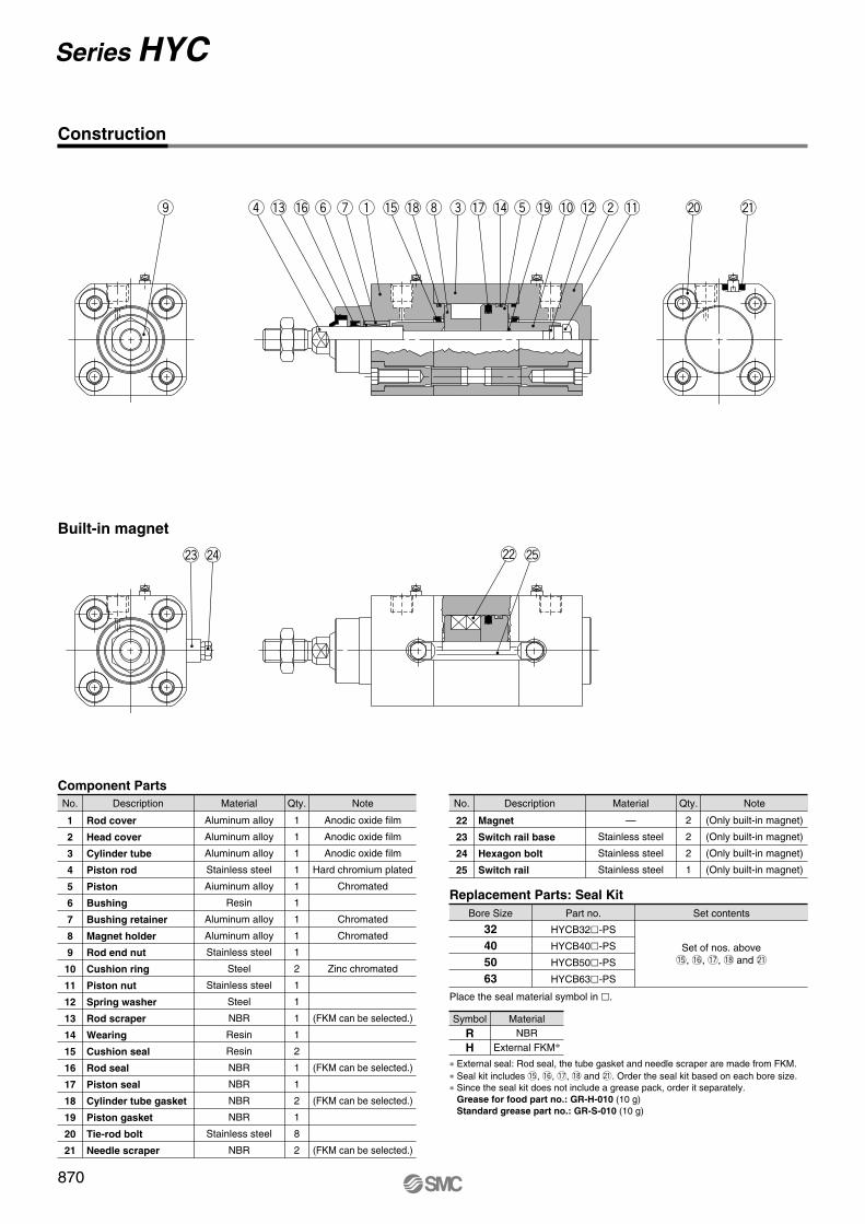
Series HYC
@2 @5
r !3 !6 y u q !5 !8 i e !7 !4 t !9 !0 !2 w !1o @0 @1
@3 @4
Construction
Built-in magnet
Component Parts
No. Description
Rod cover
Head cover
Cylinder tube
Piston rod
Piston
Bushing
Bushing retainer
Magnet holder
Rod end nut
Cushion ring
Piston nut
Spring washer
Rod scraper
Wearing
Cushion seal
Rod seal
Piston seal
Cylinder tube gasket
Piston gasket
Tie-rod bolt
Needle scraper
Material
Aluminum alloy
Aluminum alloy
Aluminum alloy
Stainless steel
Aiuminum alloy
Resin
Aluminum alloy
Aluminum alloy
Stainless steel
Steel
Stainless steel
Steel
NBR
Resin
Resin
NBR
NBR
NBR
NBR
Stainless steel
NBR
Qty.
1
1
1
1
1
1
1
1
1
2
1
1
1
1
2
1
1
2
1
8
2
Anodic oxide film
Anodic oxide film
Anodic oxide film
Hard chromium plated
Chromated
Chromated
Chromated
Zinc chromated
(FKM can be selected.)
(FKM can be selected.)
(FKM can be selected.)
(FKM can be selected.)
Note
1
2
3
4
5
6
7
8
9
10
11
12
13
14
15
16
17
18
19
20
21
No. Description
Magnet
Switch rail base
Hexagon bolt
Switch rail
Material
—
Stainless steel
Stainless steel
Stainless steel
Qty.
2
2
2
1
(Only built-in magnet)
(Only built-in magnet)
(Only built-in magnet)
(Only built-in magnet)
Note
22
23
24
25
Bore Size
32
40
50
63
Part no.
HYCB32�-PS
HYCB40�-PS
HYCB50�-PS
HYCB63�-PS
Set contents
Place the seal material symbol in �.
∗ External seal: Rod seal, the tube gasket and needle scraper are made from FKM.∗ Seal kit includes !5, !6, !7, !8 and @1. Order the seal kit based on each bore size.∗ Since the seal kit does not include a grease pack, order it separately.
Grease for food part no.: GR-H-010 (10 g)Standard grease part no.: GR-S-010 (10 g)
Replacement Parts: Seal Kit
Symbol
R
H
MaterialNBR
External FKM∗
Set of nos. above!5, !6, !7, !8 and @1
870

K
6 6.58 8
Boresize
A
22243232
AL
18202727
B
50587084
B1
17192424
C
32.538 46.556.5
D
12162020
Ee11
30354045
F
16 18.523 23
FA
5 4.55 5
FB
4444
G
14151717
H
48546969
H1
6 71010
MA
16161616
MB
3.23.24.24.2
KA
10131616
N
28283232
ZZ
146163179194
P
1/81/41/43/8
S
94105106121
T
62 71 88102
U
21212525
V
6 6 810
W
6.58.5
11 9
HA
30344047
MM
M10 x 1.25M12 x 1.25M16 x 1.5M16 x 1.5
J
M6 x 1M6 x 1
M8 x 1.25M8 x 1.25
32
40
50
63
Strokerange
500 or less500 or less600 or less600 or less
FB
FA
WV W
V
H1
MA
MB
U U
øT
øE
øE
øD
GG
K
NA
H
F N
MM
2 x P (Rc, NPT, G)
AL
(mm)
Note 1) Refer to pages 885 to 889 for details about the rod end nut, mounting bracket and accessory bracket.Note 2) When the unit is installed, ensure that dirt does not collect in the rod end (threaded portion).
871
Series HYCHygienic Design CylinderISO Standard Type
Without auto switch: HYCB32 to 63
Construction
�B
�C
ZZ + Stroke
S + Stroke
Port
Width across flats B1
Width across flats KA 2 x 4 x J
Cushion(Width across flats 4)
≅ H
A
HY�
CJ5CG5
C�M�
Individual-X�
D-�
-X�
Technicaldata

[29] [24]
10
SBSA
MA
MB
FB
FA
WV W
V
H1
U U
øT
øE
øE
øD
GG
K
N
AL
A
H
F N
MM
2 x P (Rc, NPT, G)
2 x 4 x J
11.5
ZZ + Stroke
�B
�C
S + Stroke
[Auto switch]
[Width across flats 3]
Cushion(Width across flats 4)
Width across flats B1
Width across flats KA
Port
≅ HS
≅ H
A
[≅ 25]
[≅ 3]
Note 1) The [ ] value denotes dimensions with the auto switch D-F6� mounted, which is dedicated to the Hygienic Design Cylinder.Note 2) Refer to pages 885 to 889 for details about the rod end nut, mounting bracket and accessory bracket.Note 3) When the unit is installed, ensure that dirt does not collect in the rod end (threaded portion).
K
6 6.58 8
Boresize
A
22243232
AL
18202727
B
50587084
B1
17192424
C
32.538 46.556.5
D
12162020
Ee11
30354045
F
16 18.523 23
FA
5 4.55 5
FB
4444
G
14151717
H
48546969
H1
6 71010
MA
16161616
MB
3.23.24.24.2
KA
10131616
N
28283232
P
1/81/41/43/8
S
94105106121
T
62 71 88102
U
21212525
V
6 6 810
W
6.58.5
11 9
SA
7.512
9 19
MM
M10 x 1.25M12 x 1.25M16 x 1.5M16 x 1.5
J
M6 x 1M6 x 1
M8 x 1.25M8 x 1.25
32
40
50
63
Strokerange
500 or less500 or less600 or less600 or less
Boresize
ZZ
146163179194
SB
16.523 19 24
HA
30344047
HS
50546067
32
40
50
63
(mm)
872
Series HYC
With auto switch: HYDCB32 to 63
Construction

HYG
HYDGWith auto switch
20
20
50
50 F6B
R
R
F
F
Auto switch
Nil Without auto switchRefer to the table below for selection of applicable auto switch.
Optional parts (plug bolt) should be ordered separately.Please refer to page 888 for details.
With auto switch(Built-in magnet and switch rail)
Bore size
20
25
32
40
50
63
20 mm25 mm32 mm40 mm50 mm63 mm
Port thread type
M threadRc
NPTG
ø20, ø25
ø32 to ø63
Nil
TN
TF
Sealant material
R
H
NBRExternal FKM Note)
Note) External sealant: Scraper, rod seal, O-ring (rod end) and seal washer are made from FKM.
Number of auto switches
Nil
S
n
2 pcs. 1 pc.
“n” pcs.
Grease
Nil
F
Standard grease (for non-food)Grease for food
Cylinder stroke
Refer to the next page for thestandard stroke.
Note) Select grease for food for use in a water dispersion environment or when washing a product with water.(Water resistance is insufficient with standard grease.)
Applicable Auto Switches/Refer to page 1312 for detailed auto switch specifications.
∗ Lead wire length symbols 0.5 m…………Nil (Example) F6B3 m………… L (Example) F6BL5 m………… Z (Example) F6BZ
• Refer to pages 1328 and 1329 for detailed specifications about the auto switch with pre-wired connector.∗ Auto switch is shipped not assembled with the cylinder.
∗ Auto switches marked with a “�” symbol are produced upon receipt of orders.
Type Electricalentry
Wiring (Output)Load voltage
DCAuto switch model
Lead wire length (m)∗
0.5(Nil)
3(L)
5(Z)
Applicable load
—
YesGrommet
3-wire (NPN)
2-wire
3-wire (PNP)
Pre-wiredconnector
Relay,PLC
5 V12 V
12 V
24 V
F6N
F6P
F6B
IC circuit
Indi
cato
rlig
ht
Solid
state
switch
873
Hygienic Design Cylinder
ø20, ø25, ø32, ø40, ø50, ø63Series HYG
How to Order
HY�
CJ5CG5
C�M�
Individual-X�
D-�
-X�
Technicaldata

Series HYG
20
25
32
40
50
63
Stroke (mm)
Unit: kg
20Bore size
(mm)
0.80
1.19
—
—
—
—
25
—
—
2.07
2.35
3.83
4.75
30
0.89
1.32
—
—
—
—
50
1.12
1.63
2.60
2.94
4.68
5.79
100
1.71
2.43
3.66
4.96
6.48
8.01
150
2.26
3.18
4.66
5.30
8.11
9.99
200
2.45
3.47
5.51
6.25
9.49
11.65
With auto switch (Built-in magnet and switch rail)
20
25
32
40
50
63
Stroke (mm)
Unit: kg
20Bore size
(mm)
0.77
1.17
—
—
—
—
25
—
—
2.04
2.31
3.79
4.71
30
0.86
1.29
—
—
—
—
50
1.10
1.61
2.56
2.90
4.64
5.74
100
1.68
2.40
3.61
4.12
6.43
7.95
150
2.24
3.15
4.59
5.23
8.04
9.92
200
2.42
3.43
5.43
6.17
9.41
11.56
Without auto switch
Bore size (mm)
Operatingdirection
Operating pressure (MPa)
20
25
32
40
50
63
IN
OUT
IN
OUT
IN
OUT
IN
OUT
IN
OUT
IN
OUT
0.3
71
94
113
147
181
241
317
377
495
589
841
935
0.5
118
157
189
246
302
402
528
629
825
982
1402
1559
0.7
165
220
265
344
422
563
739
880
1154
1374
1962
2182
Unit: N
Action
Fluid
Minimum operating pressure
Maximum operating pressure
Proof pressure
Lubrication
Piston speed
Cushion
Stroke length tolerance
Double acting
Air
1.0 MPa
1.5 MPa
0°C to 60°C
Not required
50 to 500 mm/s (With pressure at 1.0 MPa) Note)
Rubber bumper
Bore size (mm) 25 32 40 6320 50
0.2 MPa 0.15 MPa
20
25
32
40
50
63
20, 30, 50, 100, 150, 200
20, 30, 50, 100, 150, 200
25, 50, 100, 150, 200
25, 50, 100, 150, 200
25, 50, 100, 150, 200
25, 50, 100, 150, 200
Bore size (mm) Standard stroke (mm)
∗ Manufacture of Intermediate StrokeIntermediate strokes of 1 mm each can be produced by using spacers with standard stroke cylinders. However, intermediate strokes of 5 mm each can be produced about ø40 to 63.Example) HYG32R-57 mounts a 43mm spacer in standard stroke cylinder HYG32R-100.
Note) Use a cylinder below the allowable kinetic energy. Refer to page 877 for the allowable kinetic energy.
Specifications
+1.5 0 mm
Ambient and operating fluid
temperature
Standard Stroke
Mass
Theoretical Output
874

T T
Hygienic Design Cylinder Series HYG
W
L L
W
875
Strictly observe the values in the following table regarding rotational torque (T) pressurized to the plate (rod end).When operated outside of the acceptable range, it can decrease the machine’s service life.
20
25
32
40
50
63
Stroke (mm)
Unit: N �m
20Bore size
(mm)
0.72
1.29
—
—
—
—
25
—
—
3.23
3.56
7.83
8.83
30
0.60
1.18
—
—
—
—
50
0.57
1.04
3.07
3.39
6.80
7.67
100
0.51
0.97
2.87
3.16
5.88
6.63
150
0.45
0.83
2.59
2.86
5.25
5.92
200
0.37
0.68
2.24
2.47
4.61
5.20
20
25
32
40
50
63
Non-rotating accuracyBore size (mm)
±0.10
±0.09
±0.08
±0.08
±0.07
±0.06
∗ When the cylinder retracts (initial value), for non-rotating accuracy in load-free states and/or except the guide rod deflection, use a value that does not exceed those listed above.
Plate Allowable Rotational Torque Plate Non-rotating Accuracy
Strictly observe the values in the following table regarding allowed moment when eccentric distance is generated from the plate.When operated outside of the acceptable range, it can decrease the machine’s service life.
Plate Allowable Moment
Allowable moment(N �m)
ø20 ø25 ø32, ø40 ø50, ø63
3.57 5.07 21.5 35.3
HY�
CJ5CG5
C�M�
Individual-X�
D-�
-X�
Technicaldata
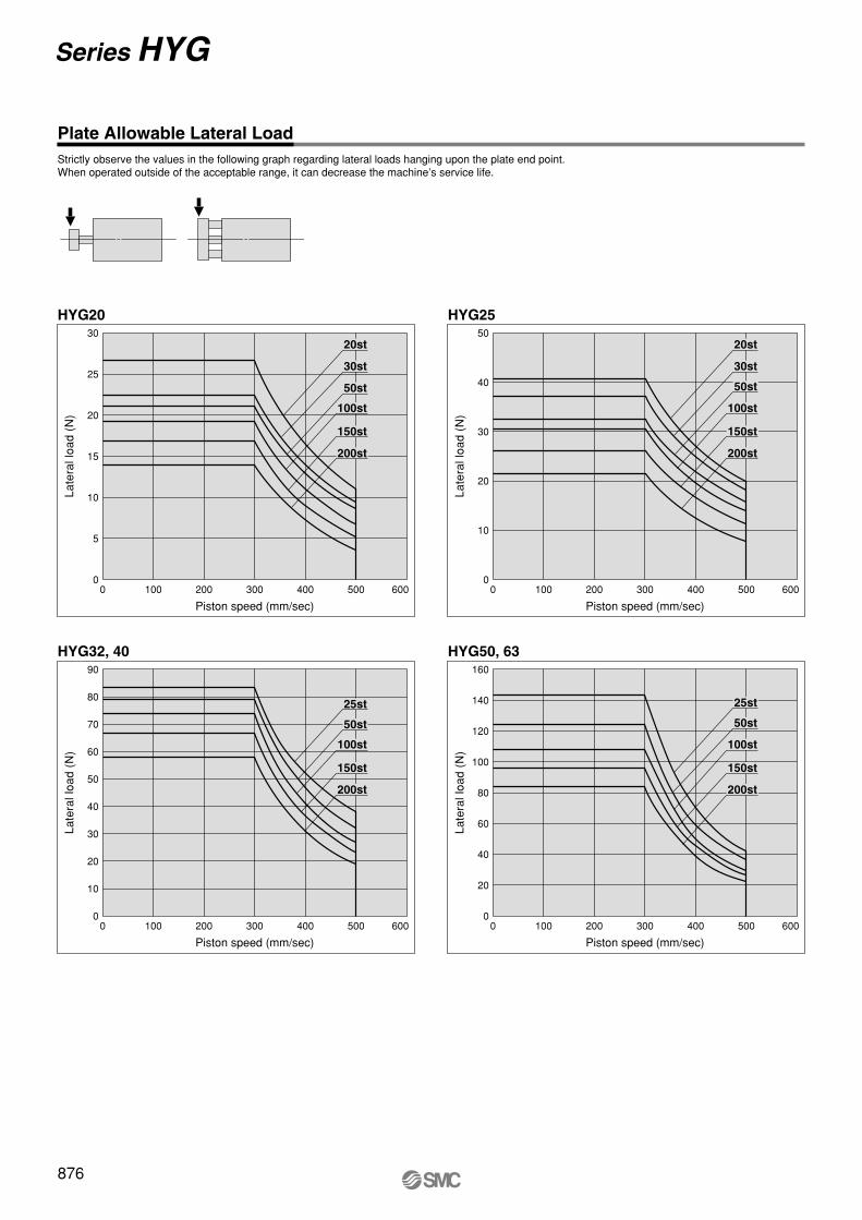
Series HYG
Piston speed (mm/sec)
Late
ral l
oad
(N)
30
25
20
15
10
5
0
HYG20
1000 200 300 400 500 600
20st
30st
50st
100st
150st
200st
50
40
30
20
10
0
Piston speed (mm/sec)
Late
ral l
oad
(N)
HYG25
0 200100 300 400 500 600
20st
30st
50st
100st
150st
200st
Piston speed (mm/sec)
Late
ral l
oad
(N)
90
80
70
60
50
40
30
20
10
0
HYG32, 40
1000 200 300 400 500 600
25st
50st
100st
150st
200st
Piston speed (mm/sec)
Late
ral l
oad
(N)
160
140
120
100
80
60
40
20
0
HYG50, 63
1000 200 300 400 500 600
25st
50st
100st
150st
200st
876
Strictly observe the values in the following graph regarding lateral loads hanging upon the plate end point.When operated outside of the acceptable range, it can decrease the machine’s service life.
Plate Allowable Lateral Load

∗ When selecting a model with a longer l dimension, be sure to choose a sufficiently large bore size.
m
υm
υ
Transfer speed: v (m/min)
Mas
s of
tran
sfer
red
obje
ct: m
(kg
)
10
1
100
5 10 20 30 40 50
Bore size ø20 and ø25
ø25
ø20
Transfer speed: v (m/min)
Mas
s of
tran
sfer
red
obje
ct: m
(kg
)
100
1000
105 10 20 30 40 50
Bore size ø32 to ø63
ø63
ø40
ø32
ø50
Maximum drive speed (V mm/s)Lo
ad m
ass
(kg)
(Supply pressure: at P = 0.5 MPa)
0
1
10
100
100
ø63
ø50
ø40
ø20
ø25
ø32
877
Hygienic Design Cylinder Series HYG
Allowable Kinetic Energy
Operating Range When Used as Stopper
CautionCaution on handling
Note) When using as a stopper Bore size ø20 and ø25: Select a model with 30 strokes or less.Bore size ø32 to ø63: Select a model with 50 strokes or less.
l ≅
50 m
m
l ≅
50 m
mW
HY�
CJ5CG5
C�M�
Individual-X�
D-�
-X�
Technicaldata

ø32 to 63
t !7 !5 !0 i e o !6 u !8 !1 !1y
w !2 r !3 !4 !9 q
@3
@2
@1
ø32 to 63
(Auto switch D-F6�)
@0
@0
Bore size
20
25
32
Part no.
HYG20�-PS
HYG25�-PS
HYG32�-PS
Set contents
Replacement Parts: Seal Kit
Place the seal material symbol in �.
Series HYG
With auto switch (Built-in magnet type)
Construction
Component Parts
No. Description
Body
Plate
Piston rod
Guide rod
Rod cover
Head cover
Piston
Bushing
Magnet holder
Bumper A
Bumper B
Scraper (Piston rod)
Scraper (Guide rod)
Hexagon bolt
Rod seal
Piston seal
O-ring (Rod end)
O-ring (Head end)
Seal washer
Magnet
Switch rail base
Switch rail
Hexagon bolt
Material
Aluminum alloy
Aluminum alloy
Stainless steel
Stainless steel
Aluminum alloy
Aluminum alloy
Aluminum alloy
Stainless steel
Aluminum alloy
Resin
Resin
Stainless steel+NBR
Stainless steel+NBR
Stainless steel
NBR
NBR
NBR
NBR
Stainless steel+NBR
—
Stainless steel
Stainless steel
Stainless steel
Qty.
1
1
1
2
1
1
1
4
1
1
1
1
2
3
1
1
1
1
3
1
2
1
2
Anodic oxide film
Anodic oxide film
Hard chromium plated
Special coated
Anodic oxide film
Chromated
Chromated
Special coated
Chromated
(FKM can be selected.)
(FKM can be selected.)
(Over ø32: 2 plugs and 1 hexagon bolt)
(FKM can be selected.)
(FKM can be selected.)
(FKM can be selected.)
(Only built-in magnet)(Over ø32: 2 magnets)
(Only built-in magnet)
(Only built-in magnet)
(Only built-in magnet)
Note
1
2
3
4
5
6
7
8
9
10
11
12
13
14
15
16
17
18
19
20
21
22
23
Caution
Please contact SMC to repair or replace seals of cylinder bore size
40 mm and above.
Please contact SMC when the cylinder has to be diassembled for the pur-pose of replacing seals, etc.
∗ External seal: Rod seal, O-ring (Rod side) and seal washer are made from FKM. ∗ Seal kit includes !5, !6, !7 and !9. Order the seal kit based on each bore size.∗ Since the seal kit does not include a grease pack, order it separately.
Grease for food part no.: GR-H-010 (10 g)Standard grease part no.: GR-S-010 (10 g)
Symbol
R
H
MaterialNBR
External FKM∗
Set of nos. at left !5, !6, !7 and !9
878

(4.7
)H
RB
RC
C
D
TB
TA
PD
QAPA
PC
RC
QA
RB
QB
E N
MA
PA
øM
B
J øL
F
UA
G
UB
879
Hygienic Design Cylinder Series HYG
Dimensions: ø20, ø25
Without auto switch: HYG20, 25
RA + Stroke
PB + Stroke
2 x
øK
RA + Stroke
A + Stroke
B + Stroke
PB + Stroke
4 x TC depth TD
4 x RE depth RF
(Supply port of rod end)
P
(Supply port of head end)
P
(Supply port of rod end)
P (Plug: Width across flats 8) (Supply port of head end)
P (Plug: Width across flats 8)
(Breathing port on guide)
M5 x 0.8 (Plug: Width across flats 8) Note 2)
(Breathing port on guide) Note 2)
M5 x 0.8
4 x RE depth RF
4 x øRD through
4 x UC depth UD
Bottom view
Boresize
78.586
88.596
52 56.5
62 66.5
B
82 86.5
A
108.5116
30 st or less 31 to 50 st 51 to 100 st Over 101 st128.5136
30 st or less 31 to 50 st 51 to 100 st Over 101 st102 106.5
20
25
Standard stroke
20, 30, 50, 100,150, 200
Boresize QA
7 8.5
RB
9.59.5
QB
68.578.5
RA
39 41.5
RC
3238
RD
5.45.4
RE
M6 x 1M6 x 1
20
25
C
3642
D
8393
E
1416
F
3038
G
8191
H
1821
J
5464
K
1216
L MB
2732
N
12.513.5
PA
1618
1012
MA
4 4.5
P
M5 x 0.8M5 x 0.8
RF
1212
TA
2429
TB
7280
TD
13 14.5
UA
1826
UB
7078
TC
M5 x 0.8M6 x 1
UC
M5 x 0.8M6 x 1
UD
1012
PB
32.534.5
PC
1415
PD
28.534
(mm)
Note 1) Refer to page 888 for details about the optional parts (plug bolt).Note 2) For piping, refer to Specific Product Precautions.
HY�
CJ5CG5
C�M�
Individual-X�
D-�
-X�
Technicaldata

[≅ 3]
[SB][SA]
(4.7
)
PD
QAPA
[29][2
9] [24]
PC
RC
H
RB
RC
C
DTB
TAQA
RB
QB
E N
MA
PA
øM
B
J øL
F
UA
G UB
11.5
10
Series HYG
Dimensions: ø20, ø25
With auto switch: HYDG20, 25
PB + Stroke
2 x
øK
RA + Stroke
RA + Stroke
A + Stroke
B + Stroke(Supply port of rod end)
P
(Supply port of head end)
P
(Supply port of rod end)
P (Plug: Width across flats 8) (Supply port of head end)P (Plug: Width across flats 8)
(Breathing port on guide)
M5 x 0.8 (Plug: Width across flats 8) Note 3)
(Breathing port on guide) Note 3)
M5 x 0.8
[Width acrossflats 3]
4 x TC depth TD
4 x RE depth RF
4 x øRD through
4 x UC depth UD
(D-F6�)[Auto switch]
4 x RE depth RF
PB + Stroke
Bottom view
[≅ 25.5]
Note 1) The [ ] value denotes dimensions with the auto switch D-F6� mounted, which is dedicated to the Hygienic Design Cylinder.Note 2) Refer to page 888 for details about the optional parts (plug bolt).Note 3) For piping, refer to Specific Product Precautions.
Boresize
78.586
88.596
52 56.5
62 66.5
B
82 86.5
A
108.5116
30 st or less 31 to 50 st 51 to 100 st Over 101 st128.5136
30 st or less 31 to 50 st 51 to 100 st Over 101 st102 106.5
20
25
Standard stroke
20, 30, 50, 100,150, 200
Boresize QA
7 8.5
RB
9.59.5
QB
68.578.5
RA
39 41.5
RC
3238
RD
5.45.4
RE
M6 x 1M6 x 1
20
25
C
3642
D
8393
E
1416
F
3038
G
8191
H
1821
J
5464
K
1216
L MB
2732
N
12.513.5
PA
1618
1012
MA
4 4.5
P
M5 x 0.8M5 x 0.8
RF
1212
TA
2429
TB
7280
TD
13 14.5
UA
1826
UB
7078
TC
M5 x 0.8M6 x 1
UC
M5 x 0.8M6 x 1
UD
1012
1617
SA
22.525.5
32.535.5
52.555.5
SB
30 st or less 31 to 50 st 51 to 100 st72.575.5
Over 101 stPB
32.534.5
PC
1415
PD
28.534
(mm)
880

PD
QAPA
RB
(4.7
)
PC
TB D
F
G
UB
MA
TA
RC
C
H
NE
PA
QB
QA
RB
RCJ
øM
B
øL
UA
881
Hygienic Design Cylinder Series HYG
Dimensions: ø32 to ø63
Without auto switch: HYG32 to 63
PB + Stroke
RA + Stroke
RA + Stroke2
x P
E
A + Stroke
B + Stroke
PB + Stroke
2 x
øK
(Breathing port on guide)M5 x 0.8 (Plug: Width across flats 8) Note 2)
(Supply port of head end)P (Plug: Width across flats PF)
(Supply port of rod end)
P (Plug: Width across flats PF)
4 x UC depth UD
(Supply port of head end)P
4 x RE depth RF
4 x RE depth RF
4 x øRD through
(Supply port of rod end)P
4 x TC depth TD(Breathing port on guide) Note 2)
M5 x 0.8
Bottom view
Boresize
116.5116.5131.5131.5
73738080
83839090
B
98 98105105
A
131.5131.5146.5146.5
146.5146.5161.5161.5
113113120120
32
40
50
63
Stroke
25, 50,100, 150,
200
C
48546478
D
112120148162
E
18182323
F
44446070
G
110118146158
H
24273239
J
78 86110124
K
20202525
L MB
41485974
N
15.515.518.518.5
16162020
MA
5566
Boresize
32
40
50
63
PB
42.540.541.545
PC
16172223
PD
37.842.552 61
PE
4.74.76.26.2
PF
13131616
QA
11 11 12.512
QB
95103129143
RA
51313135
RC
46506376
RD
6.66.68.68.6
RF
16162020
TA
32384357
TD
20202222
UA
30304050
UB
96104130130
UD
13.513.517 17
UC
M8 x 1.25M8 x 1.25M10 x 1.5M10 x 1.5
TB
96104127141
TC
M8 x 1.25M8 x 1.25M10 x 1.5M10 x 1.5
RE
M8 x 1.25M8 x 1.25M10 x 1.5M10 x 1.5
RB
11.530 32 34
106.5106.5121.5121.5
TF
P
G 1/8G 1/8G 1/4G 1/4
TN
NPT 1/8NPT 1/8NPT 1/4NPT 1/4
Nil
Rc 1/8Rc 1/8Rc 1/4Rc 1/4
PA
20 20.522 24
(mm)
25 st or less 26 to 50 st 51 to 100 st Over 101 st 25 st or less 26 to 50 st 51 to 100 st Over 101 st
Note 1) Refer to page 888 for details about the optional parts (plug bolt).Note 2) For piping, refer to Specific Product Precautions.
HY�
CJ5CG5
C�M�
Individual-X�
D-�
-X�
Technicaldata

RB
RC
[≅ 3]
[SB][SA]
PD
QAPA
(4.7
)
[≅ 25]
[29][2
9]
[24] 10
PC
TB D
F
G UB
MA
TA
C
H11.5
NE
PA
QB
QA
RB
RCJ
øM
B
øL
UA
882
Series HYG
Dimensions: ø32 to ø63
With auto switch: HYDG32 to 63
RA + Stroke4 x RE depth RF
PB + Stroke
RA + Stroke
2 x
PE
A + Stroke
B + Stroke
PB + Stroke
2 x
øK
(D-F6�)
[Width acrossflats 3]
(Breathing port on guide)
M5 x 0.8 (Plug: Width across flats 8) Note 3)
(Supply port of head end)
P (Plug: Width across flats PF)
(Supply port of rod end)
P (Plug: Width across flats PF)
4 x UC depth UD P
[Auto switch]4 x RE depth RF
4 x øRD through
(Supply port of rod end)P
4 x TC depth TD(Breathing port on guide) Note 3)
M5 x 0.8
(Supply port of head end)
Bottom view
Note 1) The [ ] value denotes dimensions with the auto switch D-F6� mounted, which is dedicated to the Hygienic Design Cylinder.Note 2) Refer to page 888 for details about the optional parts (plug bolt).Note 3) For piping, refer to Specific Product Precautions.
Boresize
116.5116.5131.5131.5
73738080
83839090
B
98 98105105
A
131.5131.5146.5146.5
146.5146.5161.5161.5
113113120120
32
40
50
63
Stroke
25, 50,100, 150,
200
C
48546478
D
112120148162
E
18182323
F
44446070
G
110118146158
H
24273239
J
78 86110124
K
20202525
L MB
41485974
N
15.515.518.518.5
TF
P
G 1/8G 1/8G 1/4G 1/4
TN
NPT 1/8NPT 1/8NPT 1/4NPT 1/4
Nil
Rc 1/8Rc 1/8Rc 1/4Rc 1/4
16162020
MA
5566
Boresize
32
40
50
63
PB
42.540.541.545
PC
16172223
PD
37.842.552 61
PE
4.74.76.26.2
PF
13131616
QA
11 11 12.512
QB
95103129143
RA
51313135
RC
46506376
RD
6.66.68.68.6
RF
16162020
TA
32384357
TD
20202222
UA
30304050
UB
96104130130
UD
13.513.517 17
UC
M8 x 1.25M8 x 1.25M10 x 1.5M10 x 1.5
TB
96104127141
TC
M8 x 1.25M8 x 1.25M10 x 1.5M10 x 1.5
RE
M8 x 1.25M8 x 1.25M10 x 1.5M10 x 1.5
RB
11.530 32 34
22.521 21 23.5
46.548 55 52.5
SA 26 to50 st
36.538 45 42.5
25 stor less
61.563 70 67.5
76.578 85 82.5
SB
51 to100 st
Over101 st
25 stor less
26 to50 st
51 to100 st
Over101 st
25 stor less
26 to50 st
51 to100 st
Over101 st
106.5106.5121.5121.5
PA
20 20.522 24
(mm)
A 33 B ≈ Hs
24.5
≅ Hs
16
B
SM
C
29A
SM
C
≅ Hs
16SM
C
B29A
SM
C
883
Hygienic Design Cylinder Series HY �
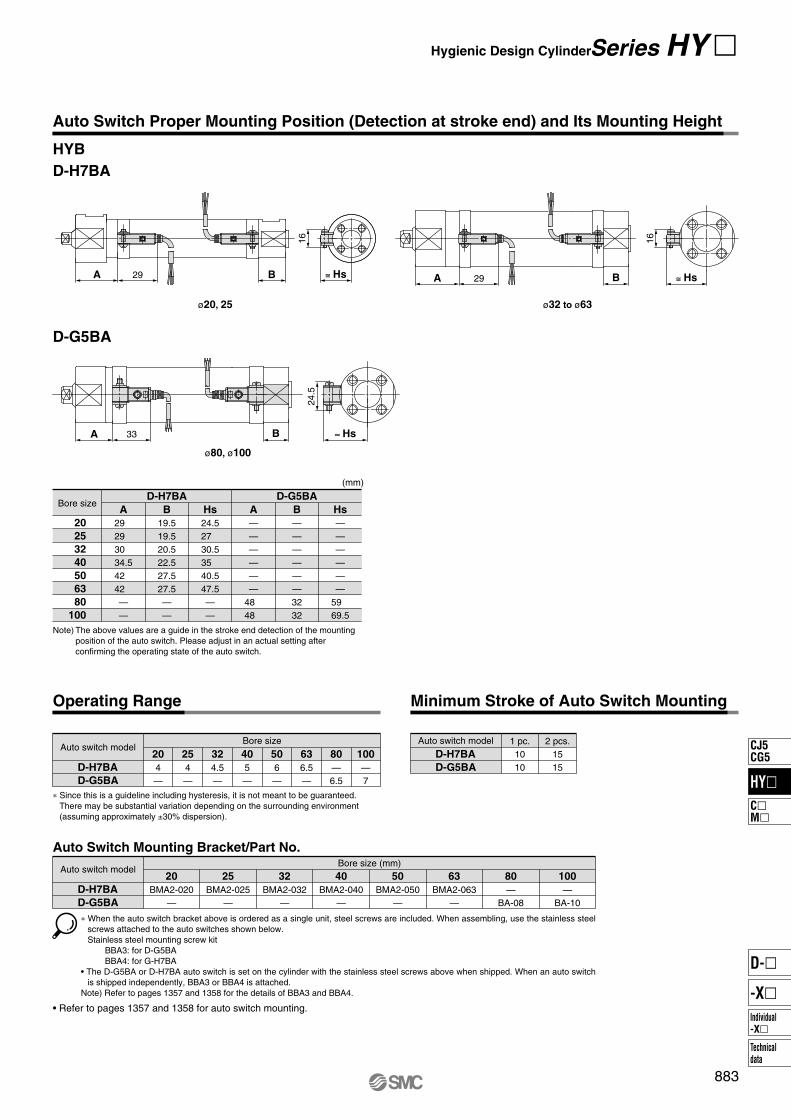
Auto Switch Proper Mounting Position (Detection at stroke end) and Its Mounting Height
HYB
D-H7BA
ø20, 25 ø32 to ø63
D-G5BA
ø80, ø100
D-H7BA D-G5BA
ABore size
(mm)
20
25
32
40
50
63
80
100
29 29 30 34.542 42 ——
B
19.519.520.522.527.527.5——
Hs
24.527 30.535 40.547.5——
A
——————
48 48
B
——————3232
Hs
——————
59 69.5
Note) The above values are a guide in the stroke end detection of the mounting position of the auto switch. Please adjust in an actual setting after confirming the operating state of the auto switch.
D-H7BA
D-G5BA
Auto Switch Mounting Bracket/Part No.
Auto switch modelBore size (mm)
20
BMA2-020—
25
BMA2-025—
32
BMA2-032—
40
BMA2-040—
50
BMA2-050—
63
BMA2-063—
80
—BA-08
100
—BA-10
∗ When the auto switch bracket above is ordered as a single unit, steel screws are included. When assembling, use the stainless steel screws attached to the auto switches shown below.Stainless steel mounting screw kit
BBA3: for D-G5BA BBA4: for G-H7BA• The D-G5BA or D-H7BA auto switch is set on the cylinder with the stainless steel screws above when shipped. When an auto switch
is shipped independently, BBA3 or BBA4 is attached.Note) Refer to pages 1357 and 1358 for the details of BBA3 and BBA4.
• Refer to pages 1357 and 1358 for auto switch mounting.
D-H7BA
D-G5BA
Operating Range
Auto switch model100
—7
Bore size
80
—6.5
63
6.5—
50
6—
40
5—
32
4.5—
25
4—
20
4—
Minimum Stroke of Auto Switch Mounting
2 pcs.1515
D-H7BA
D-G5BA
Auto switch model 1 pc.1010
∗ Since this is a guideline including hysteresis, it is not meant to be guaranteed. There may be substantial variation depending on the surrounding environment (assuming approximately ±30% dispersion).
HY�
CJ5CG5
C�M�
Individual-X�
D-�
-X�
Technicaldata

Series HYQ
Series HYC
Series HYG≅ 25B
A
≅ HsB
A
≅ 25B
A
Series HY �
D-F6�
D-F6�
D-F6�
Auto Switch Proper Mounting Position (Detection at stroke end) and Its Mounting Height
BABore size
30 st or less 31 to 50 st 51 to 100 st Over 101 st
(mm)
20
25
32
40
50
63
16 17 22.521 21 23.5
22.525.536.538 45 42.5
32.535.546.548 55 52.5
52.555.561.563 70 67.5
72.575.576.578 85 82.5
HsBABore size
(mm)
32
40
50
63
7.512 9
19
16.523 19 24
50546067
BABore size20
25
32
40
50
63
6.5 6.5 8.510.510.59
10.511 16 16 17 18
(mm)
Note) The above values are a guide in the stroke end detection of the mounting position of the auto switch. Please adjust in an actual setting after confirming the operating state of the auto switch.
Note) The above values are a guide in the stroke end detection of the mounting position of the auto switch. Please adjust in an actual setting after confirming the operating state of the auto switch.
Note) The above values are a guide in the stroke end detection of the mounting position of the auto switch. Please adjust in an actual setting after confirming the operating state of the auto switch.
Operating Range
Tighten the screw within the following torque range
when the auto switch mounting rail is installed during
maintenance.
Screw sizeM4
Tightening torque (N �m)1.1 to 1.9
Tighten the screw within the following torque range
when the auto switch is installed on the mounting rail.
Tightening torque (N �m)0.8 to 1.4
7—7
6—7
7.57.58
7.57.57.5
7.57.57.5
7.57.57.5
20 25 32 40 50 63
HYQ
HYC
HYG
SeriesBore size
Unit: Operating range [mm]
Minimum Stroke of Auto Switch Mounting
510
1015
HYQ, HYC
HYG
Series 1 pc. 2 pcs.
Auto Switch Mounting (HYQ, HYC, HYG common)
Loosen the mounting screw, then insert the mounting groove into the rail.
Rail
After deciding the position, tighten the mounting screw.
Note) Since this is a guideline including hysteresis, it is not meant to be guaranteed. There may be substantial variation depending on the surrounding environment (assuming approximately ±30% dispersion).
Proper tightening torqueWhen the mounting screw is tightened, use a special tool or torque wrench. The tightening torque of the M3 mounting screw should be 0.8 to 1.4 N �m.
D-F6�
Auto switchmodel
D-F6�
Auto switch model
884

Series HYC
Series HYB
Series HYQ
LZ
ZC + StrokeZB + Stroke
LQ + Stroke
LT
LX
LH
LY
Y X
ZA + Stroke
LC + StrokeX Y
4 x øLD
Foot bracket material: Stainless steel Mounting bolt material: Stainless steel
(mm)
M X
LH
LY
Y
LT
LC + Stroke
LT Y X M LX
LZ
4 x øLD
Note 1) Order two foot brackets per cylinder. One mounting bracket is attached with two foot brackets and four mounting bolts.Note 2) Contact SMC for HYB ø20, ø25.
Bore size X
16 16.521.521.528 30
Y
6 6.511.511.517 15
LD
7.2 7.210 12 12 14
LH
253040455570
LC
455155556060
LT
334446
LX
44 54 66 82100120
LY
44 53.569 81
99.5125
LZ
60 75 90110130160
M
3.54 5.57 7 8
32
40
50
63
80
100
Bracketpart no.
0.060.080.170.230.360.69
Mass(kg)
CG-L032SUS
CG-L040SUS
CG-L050SUS
CG-L063SUS
CG-L080SUS
CG-L100SUS
Foot bracket material: Stainless steel Mounting bolt material: Stainless steel
(mm)
M5 x 0.8M6 x 1.0
M8 x 1.25M10 x 1.5M10 x 1.5
M12 x 1.75
Mounting bolt
Note 1) One mounting bracket is attached with one foot bracket and two mounting bolts.Note 2) Two foot brackets per cylinder should be ordered.Note 3) Contact SMC for HYQ ø20, ø25.
Bore size X
24283232
Y
11101111
LD
7999
LH
32364550
LC
142161170185
LQ
109 121.5140.5141
LT
4455
LX
32364550
LY
57658092
LZ
49.557.569 84
ZA
HYCHYQ
Without auto switchHYDQ
With auto switch
177198218233
ZB
107 115.5133.5134
ZC
129 139.5165.5166
ZB
122 130.5148.5149
ZC
144 154.5180.5181
M6 x 1 x 18LM6 x 1 x 18L
M8 x 1.25 x 20LM8 x 1.25 x 20L
32
40
50
63
Bracketpart no.
100120210260
Mass(g) Mounting bolt
HY-L032SUS
HY-L040SUS
HY-L050SUS
HY-L063SUS
885
Mounting Brackets
Foot Bracket
HY�
CJ5CG5
C�M�
Individual-X�
D-�
-X�
Technicaldata

Series HYC (Rod end and head end are common.)
Series HYB (Rod end)
Series HYQ(Rod end and head end are common.)
ZC + Stroke
ZB + Stroke
ZA + Stroke
FE FT
øF
d
FX
B FY
FZ
4 x øFD
Note 1) One mounting bracket is attached with 4 mounting bolts. Note 2) Contact SMC for HYQ ø20, ø25.
B
49.557.569 82
FD
7999
FE
6 8.5
11 11
FT
10101212
FX
64 72 90100
FY
32364550
FZ
80 90110120
Fd
29343944
ZA
HYCHYQ
Without auto switchHYDQ
With auto switch
152169187202
ZB
82 87.5102.5103
ZC
104 111.5134.5135
ZB
97102.5117.5118
ZC
119 126.5149.5150
M6 x 1 x 18LM6 x 1 x 18L
M8 x 1.25 x 20LM8 x 1.25 x 20L
32
40
50
63
260320580770
Mounting bolt
HY-F032SUS
HY-F040SUS
HY-F050SUS
HY-F063SUS
Flange bracket material: Stainless steelMounting bolt material: Stainless steel
(mm)
Series HY �
Note 1) One mounting bracket is attached with one flange bracket and four mounting bolts.Note 2) Contact SMC for HYB ø20, ø25.
Bore size FT
6 6 9 9 910
FX
38 46 58 70 82100
FZ
50 60 75 90100125
FD
6.6 6.69
11 11 14
32
40
50
63
80
100
0.100.150.260.520.661.16
CG-F032SUS
CG-F040SUS
CG-F050SUS
CG-F063SUS
CG-F080SUS
CG-F100SUS
Flange bracket material: Stainless steelMounting bolt material: Stainless steel
(mm)
�FX±0.15 FT4 x øFD
�FZ
Rod end flange bracket (Material: Stainless steel)
Flange Bracket
Bracketpart no.
Mass(kg)
Bore size Bracketpart no.
Mass(g)
886

Series HYC
Series HYC
Series HYQ
Series HYQ
Df8
10121216
L
53606878
d
9.611.511.515.2
l
46536171
m
2.32.32.32.3
t
1.21.21.21.2
C type for shaft 10C type for shaft 12C type for shaft 12C type for shaft 16
Note 1) One clevis pin is attached with two retaining rings.Note 2) Contact SMC for HYQ ø20, ø25.
32
40
50
63
Applied retaining ring
40 60 70130
HY-E03SUS
HY-E04SUS
HY-E05SUS
HY-E06SUS
L
22252732
RR
10121216
U
12151720
CDH9
10121216
CX-0.2-0.6
26283240
ZA
HYC
164184202222
ZB
174196214238
Note 1) One mounting bracket is attached with 4 mounting bolts. Note 2) Contact SMC for HYQ ø20, ø25.
32
40
50
63
200310440760
HY-C032SUS
HY-C040SUS
HY-C050SUS
HY-C063SUS
ZC
94 102.5117.5123
ZD
104114.5129.5139
ZE
116126.5149.5155
ZF
126138.5161.5171
32
40
50
63
HY-C032SUS
HY-C040SUS
HY-C050SUS
HY-C063SUS
ZC
109117.5132.5138
ZD
119129.5144.5154
ZE
131141.5164.5170
ZF
141153.5176.5186
32
40
50
63
M6 x 1 x 18LM6 x 1 x 18L
M8 x 1.25 x 20LM8 x 1.25 x 20L
HY-C032SUS
HY-C040SUS
HY-C050SUS
HY-C063SUS
L
22252732
RR
10121216
CZh14
45526070
U
12151720
CDH9 CXH14
10121216
26283240
Note 1) One mounting bracket is attached with 4 mounting bolts and clevis pin(HY-E0�SUS) and retaining rings.
Note 2) Contact SMC for HYQ ø20, ø25.
32
40
50
63
220350490810
HY-D032SUS
HY-D040SUS
HY-D050SUS
HY-D063SUS
ZA
164184202222
ZB
174196214238
ZC
HYC
94102.5117.5123
ZD
104114.5129.5139
ZE
116126.5149.5155
ZF
126138.5161.5171
32
40
50
63
HY-D032SUS
HY-D040SUS
HY-D050SUS
HY-D063SUS
ZC
109117.5132.5138
ZD
119129.5144.5154
ZE
131141.5164.5170
ZF
141153.5176.5186
32
40
50
63
M6 x 1 x 18LM6 x 1 x 18L
M8 x 1.25 x 20LM8 x 1.25 x 20L
HY-D032SUS
HY-D040SUS
HY-D050SUS
HY-D063SUS
ZE + Stroke
ZF + StrokeZD + Stroke
ZC + Stroke
CX-0.2-0.6
ZB + Stroke
ZA + Stroke RR
L
U
øCDH9
ZE + Stroke
ZF + StrokeZD + Stroke
ZC + Stroke
CZ
CX
ZB + Stroke
ZA + Stroke RRL
U
mm
l t
L
t
øD
f8
ød
øCDH9
Single clevis bracket material: Stainless steelMounting bolt material: Stainless steel
(mm)
Double clevis bracket material: Stainless steelMounting bolt material: Stainless steel
(mm)
Pin material: Stainless steelRetaining ring material: Stainless steel
(mm)
Mounting Brackets Series HY �
887
Boresize
Bracketpart no.
Mass(g)
Boresize
HYQ / without auto switchBracketpart no.
Boresize
HYDQ / with auto switchBracketpart no. Mounting bolt
Double Clevis Bracket
Boresize
Bracketpart no.
Mass(g)
Boresize
HYQ / without auto switchBracketpart no.
Boresize
HYDQ / with auto switchBracketpart no. Mounting bolt
Clevis Pin
Boresize
Bracketpart no.
Mass(g)
Single Clevis Bracket
HY�
CJ5CG5
C�M�
Individual-X�
D-�
-X�
Technicaldata

Cover material: Stainless steelMounting bolt material: Stainless steel
(mm)
Cover material: Stainless steelMounting bolt material: Stainless steel
(mm)
Cover material: Stainless steelMounting bolt material: Stainless steel
(mm)
Cover material: Stainless steelMounting bolt material: Stainless steel
(mm)
Series HYQ, HYC Series HYC Series HYB, HYG
C
BH
d M
BZB2
BM
BZ
M
B2
BM
d CBH
20
25
32
40
50, 63
M6 x 1.0M8 x 1.25
M10 x 1.25M12 x 1.25M16 x 1.5
3.656710
1013171924
11.515
19.621.927.7
NTH-02SUS
NT-02SUS
NT-03SUS
NTH-04SUS
NTH-05SUS
Material: Stainless steel(mm)
B2 BM
32, 40
50, 63
1012
M6 x 1.0M8 x 1.25
HYC-H03SUS
HYC-H05SUS
Note) The above part number is attached with 4 bolts.
Material: Stainless steel(mm)
MBZ
2224
68
BMB2 MBZ
8101317
M5 x 0.8M6 x 1.0
M8 x 1.25M10 x 1.5
9.512 15.519
3.54 5.57
HYG-H020SUS
HYG-H025SUS
HYG-H032SUS
HYG-H050SUS
(mm)HYG
HYBB2 MBZBM
20
25
32
40
50
63
80
100
7 8 81013171719
M4 x 0.7M5 x 0.8M5 x 0.8M6 x 1.0M8 x 1.25M10 x 1.5M10 x 1.5M12 x 1.75
9 9.5 9.512 15.519 19 24
3 3.53.54 5.57 7 8
HYB-H020SUS
HYB-H025SUS
HYB-H040SUS
HYB-H050SUS
HYB-H063SUS
HYB-H100SUS
Material: Stainless steel(mm)
Series HYQ/ø20, ø25
Series HYQ/ø32 to ø63
M5 x 0.8 x 10LM6 x 1.0 x 10L
Installation bolt18.520.5
5.56.6
2226
32.239.2
DCBA
HYQ-HA020SUS
HYQ-HA025SUS
Part no.
M6 x 1.0 x 10LM6 x 1.0 x 10LM8 x 1.25 x 10LM8 x 1.25 x 10L
Installation bolt22.526.532.532.5
6.66.68.88.8
32.538
46.556.5
48.856.868.283.2
DCBA
HYQ-HA032SUS
HYQ-HA040SUS
HYQ-HA050SUS
HYQ-HA063SUS
Part no.M6 x 1.0 x 10LM6 x 1.0 x 10L
M8 x 1.25 x 10LM8 x 1.25 x 10L
Installation bolt6.66.68.88.8
32.538
46.556.5
48.856.868.283.2
CBA
HYQ-HB032SUS
HYQ-HB040SUS
HYQ-HB050SUS
HYQ-HB063SUS
Part no.
M5 x 0.8 x 10LM6 x 1.0 x 10L
Installation bolt5.56.6
2226
32.239.2
CBA
HYQ-HB020SUS
HYQ-HB025SUS
Part no.
Note) One mounting bracket is attached with two mounting bolts. Note) One mounting bracket is attached with two mounting bolts.
Note) One mounting bracket is attached with four mounting bolts. Note) One mounting bracket is attached with four mounting bolts.
4 x ø
C
�B�At=1
4 x ø
CøD
�B�At=1
2 x ø
C
�A�B
t=1
øD2
x øC
�A
�B
t=1
Rod End Nut Plug Bolt
Applicable bore sizePart no. Applicable bore sizePart no.
Part no.
Note) The above part number is attached with 4 bolts.
Note) The above part number is attached with 4 bolts.
Applicable bore sizePart no.
External Cover
Head endRod end
Head endRod end
888
Options
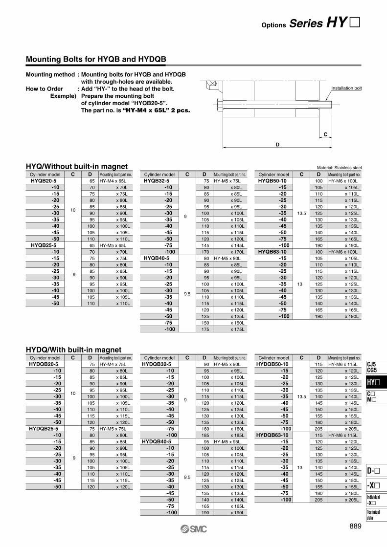
13
13.5
DC
9.5
9
9
DC
10
65707580859095
10010511065707580859095
100105110
HY-M4 x 65L x 70L x 75L x 80L x 85L x 90L x 95L x 100L x 105L x 110L
HY-M5 x 65L x 70L x 75L x 80L x 85L x 90L x 95L x 100L x 105L x 110L
DC
HYQB20-5
-10
-15
-20
-25
-30
-35
-40
-45
-50
HYQB25-5
-10
-15
-20
-25
-30
-35
-40
-45
-50
7580859095
10010511011512014517080859095
100105110115120125150175
HY-M5 x 75L x 80L x 85L x 90L x 95L x 100L x 105L x 110L x 115L x 120L x 145L x 170L
HY-M5 x 80L x 85L x 90L x 95L x 100L x 105L x 110L x 115L x 120L x 125L x 150L x 175L
HYQB32-5
-10
-15
-20
-25
-30
-35
-40
-45
-50
-75
-100
HYQB40-5
-10
-15
-20
-25
-30
-35
-40
-45
-50
-75
-100
100105110115120125130135140165190100105110115120125130135140165190
HY-M6 x 100L x 105L x 110L x 115L x 120L x 125L x 130L x 135L x 140L x 165L x 190L
HY-M6 x 100L x 105L x 110L x 115L x 120L x 125L x 130L x 135L x 140L x 165L x 190L
HYQB50-10
-15
-20
-25
-30
-35
-40
-45
-50
-75
-100
HYQB63-10
-15
-20
-25
-30
-35
-40
-45
-50
-75
-100
HYQ/Without built-in magnet
13
13.5
DC
9.5
9
9
DC
10
DC
7580859095
1001051101151207580859095
100105110115120
HY-M4 x 75L x 80L x 85L x 90L x 95L x 100L x 105L x 110L x 115L x 120L
HY-M5 x 75L x 80L x 85L x 90L x 95L x 100L x 105L x 110L x 115L x 120L
HYDQB20-5
-10
-15
-20
-25
-30
-35
-40
-45
-50
HYDQB25-5
-10
-15
-20
-25
-30
-35
-40
-45
-50
9095
10010511011512012513013516018595
100105110115120125130135140165190
HY-M5 x 90L x 95L x 100L x 105L x 110L x 115L x 120L x 125L x 130L x 135L x 160L x 185L
HY-M5 x 95L x 100L x 105L x 110L x 115L x 120L x 125L x 130L x 135L x 140L x 165L x 190L
HYDQB32-5
-10
-15
-20
-25
-30
-35
-40
-45
-50
-75
-100
HYDQB40-5
-10
-15
-20
-25
-30
-35
-40
-45
-50
-75
-100
115120125130135140145150155180205115120125130135140145150155180205
HY-M6 x 115L x 120L x 125L x 130L x 135L x 140L x 145L x 150L x 155L x 180L x 205L
HY-M6 x 115L x 120L x 125L x 130L x 135L x 140L x 145L x 150L x 155L x 180L x 205L
HYDQB50-10
-15
-20
-25
-30
-35
-40
-45
-50
-75
-100
HYDQB63-10
-15
-20
-25
-30
-35
-40
-45
-50
-75
-100
HYDQ/With built-in magnet
Mounting Bolts for HYQB and HYDQB
Mounting method : Mounting bolts for HYQB and HYDQB
with through-holes are available.
How to Order : Add “HY-” to the head of the bolt.
Example) Prepare the mounting bolt
of cylinder model “HYQB20-5”.
The part no. is “HY-M4 x 65L” 2 pcs.
C
D
Installation bolt
Options Series HY �
889
Mounting bolt part no.Cylinder modelMounting bolt part no.Cylinder modelMounting bolt part no.Cylinder model
Material: Stainless steel
Mounting bolt part no.Cylinder modelMounting bolt part no.Cylinder modelMounting bolt part no.Cylinder model
HY�
CJ5CG5
C�M�
Individual-X�
D-�
-X�
Technicaldata

Caution on Design
1. Speed adjustment should be conducted in the environment where the cylinder is used.In a different environment, the speed adjustment may be incor-rect.
2. There are possibilities that dust may accumu-late by the usage condition in the thread part and brackets for mounting of this products.Do measures according to the usage condition when you mount it.
Caution
Caution
Mounting
1. Design the aptitude enough by thinking about the rigidity of mount because the cy-linder puts out big power.
2. Tighten in following tightening torque when you install the auto switch rail when repair-ing it.
[Series HYC and HYQ]
3. Do not apply any force to lead wires when auto switch is mounted on cylinder.Never apply any force to lead wires. This may not only cause broken lead wires, but it may cause internal elements of the switch to be damaged by the stress. Moreover, the switch might not operate when force applys to the lead wire and the distance between the switch and the cylinder become long.
4. Pay attention to magnetic substance density between the auto switch and the cylinder body and the circumference.When a magnetic substance is brought into close proximity with an auto switch and cylinder, it may cause the auto switch to malfunction due to a loss of the magnetic force inside the cylinder.
5. When the cylinder, the support bracket and the plug bolt are mounted, tighten them with-in below tightening torque.
[Series HYB]
Thread size Tightening torque (N �m)M4 1.1 to 1.9
Bore size Tightening torque (N �m)Thread sizeø20
ø25, ø32ø40ø50
ø63, ø80ø100
M4 x 0.7M5 x 0.8M6 x 1
M8 x 1.25M10 x 1.5
M12 x 1.75
1.1 to 1.92.1 to 3.93.7 to 6.7
8.8 to 16.217.2 to 31.829.4 to 54.6
1. Do not put hands or fingers, etc. between the plate and body. [Series HYG]Care should be taken that hands or fingers do not get caught in between the cylinder body and the plate when air pressure is applied.
Warning
Operating Environment
Caution
Food
Non-food zoneInstallable
Container
Food zoneNot installable
Splash zoneInstallable
2. When a detergent or chemical liquid other than water is splashed on the cylinder, the cylinder’s service life may be substantially shortened. Please contact us for details.
3. When washing a cylinder with steam, please observe the allowable temperature range of the cylinder and perform for a short period of time.
4. When washing a cylinder with a brush, etc., please do not apply excessive force to the auto switch’s lead wire, etc.
1. Avoid installing and using a cylinder inside a food zone. <Not installable> Food zone An environment where food which will be
sold as merchandize, directly touches the cylinder’s components.
<Installable>Splash zone An environment where food which will not
be sold as merchandize, directly touches the cylinder's components.
Non-food zone An environment where there is no contact with food.
890
Series HY �Specific Product Precautions 1Be sure to read before handling. Refer to front matters 54 and 55 for Safety Instructions
and pages 3 to 11 for Actuator and Auto Switch Precautions.

891
Mounting
Caution
7. When the cylinder, the plug bolt and the load are mounted, tighten within below tightening torque. [Series HYG]
Bore size Tightening torque (N �m)Thread sizeø20, 25ø32, 40ø50, 63
M6 x 1M8 x 1.25M10 x 1.5
3.7 to 6.78.8 to 16.2
17.2 to 31.8
Lower Side Mounting
Bore size Tightening torque (N �m)Thread sizeø20, 25ø32, 40ø50, 63
M5 x 0.8M6 x 1
M8 x 1.25
2.1 to 3.93.7 to 6.7
8.8 to 16.2
Top Mounting
1. Lubrication of Hygienic Design Cylinder (standard grease use goods). This unit can be operated without lubrication. If lubrication is performed, build in the lubricator in the circuit, use turbine oil Class 1 (with no additives) ISO VG-32.Moreover, the malfunction will occur if the lubrication is discon-tinued on the way because the disappearance of the initial lu-brication part. Lubricate without fail continuously. Consult with SMC if other lubricant are used.
Lubrication
Caution
Caution
8. Install the load when the piston rod is retrac-ted. [Series HYG]The twist occurs in the guide part if the load is installed on the plate when the piston rod is extended, and it causes the mal-function.
Tightening torque (N �m)Thread sizeM5 x 0.8M6 x 1
M8 x 1.25M10 x 1.5
2.1 to 3.93.7 to 6.7
8.8 to 16.217.2 to 31.8
Plug Bolt Mounting (Optional)
6. When the cylinder, the support bracket and the external cover are mounted, tighten them within below tightening torque. [Series HYQ]
Bore size Tightening torque (N �m)Thread sizeø20
ø25, 32, 40ø50, 63
M5 x 0.8M6 x 1
M8 x 1.25
2.1 to 3.93.7 to 6.7
8.8 to 16.2
Bore size Tightening torque (N �m)Thread sizeø32, 40ø50, 63
M6 x 1M8 x 1.25
3.7 to 6.78.8 to 16.2
[Series HYC]
Bore size Tightening torque (N �m)Thread sizeø20ø25
ø32, 40ø50, 63
M5 x 0.8M6 x 1
M8 x 1.25M10 x 1.5
2.1 to 3.93.7 to 6.7
8.8 to 16.217.2 to 31.8
Bottom Mounting or Load Mounting
Load mounting
W
Bottom mounting
Series HY �Specific Product Precautions 2Be sure to read before handling. Refer to front matters 54 and 55 for Safety Instructions
and pages 3 to 11 for Actuator and Auto Switch Precautions.
HY�
CJ5CG5
C�M�
Individual-X�
D-�
-X�
Technicaldata

892
1. Readjust with the cushion needle. Readjust the cushion needle installed in the cover according to the load size and the operating speed before use, though it is adjusted to near the fully closed states when it ships. When the cushion adjuster is rotated to clockwise, the throttle strengthens becomes tight and the cushion strengthens will be good.
2. Do not use the cushion needle for a long term in the fully closed states. It causes the damage of the seal.
3. Torque to the cushion adjuster should be be-low of the following torque when the cushion needle is adjusted.
Do not exceed the torque mentioned above. Otherwise it cau-ses the damage.
4. Do not exceed the adjustable range of cush-ion needle.If cushion needle is rotated with the torque over adjustable range, it causes the damage.
Cushion (HYC)
Caution
Tightening torque (N �m)0.5
Bore size Rotationsø32, 40ø50, 63
4 or less5 or less
Piping
Caution
2. Plug piping ports and breathing port on guide according to the operating conditions. [Series HYG]
3. Use the piping tube installed in the breathing port for guide is more than ø4 in bore size and within 3 m in length, otherwize the cylin-der piston speed might decrease.
Bore size Tightening torque(N �m)
Plug widthacross flats
Plug threadsize
ø20, 25
ø32, 40ø50, 63
M5
1/81/4
After tightening by hand, tighten1/6 turn.
7 to 912 to 14
8
1316
Piping Port
Breathing Port for Guide
Bore size Tightening torque(N �m)
Plug widthacross flats
Plug threadsize
ø20 to ø63 M5 After tightening by hand, tighten1/6 turn.8
Piping port
Breathing port on guide
2.Lubrication to Hygienic Design Cylinder (food compatible grease use goods). If this unit is lubricated, it might cause the malfunction. Moreover, when a grease out of specification is used, it causes the malfunction. • Place a purchase order with the following model number
when only the grease for maintenance is necessary.Standard grease (for non-food) GR-S-010 (10 g)Food compatible grease GR-H-010 (10 g)
3. Do not wipe off the grease adhering to the slid-ing part of the air cylinder.It might cause the malfunction when compulsorily peeling off the adhering grease to the sliding parts. If the cylinder oper-ates the long distance, the sliding parts might become black. In that case, the actuation becomes possible for a long term when the grease of the sliding parts is wiped off once, and it greases it again.(Wipe off by water. If alcohol and a special solvent are used, the seal might be damaged.)
Lubrication
Caution1. This product might be damaged if the com-
pressed air is supplied to the breathing port for guide, so do not supply it. [Series HYG]
<Example>
• Piping is connected in the breathing port on guide, breathing at general environment is possible.
Water dispersion environment
Generalenvironment
Breathing port on guide
Series HY �Specific Product Precautions 3Be sure to read before handling. Refer to front matters 54 and 55 for Safety Instructions
and pages 3 to 11 for Actuator and Auto Switch Precautions.

893
1. If the sliding parts is washed, the grease will wash out and the service life will be shorten, keep washing at a minimum.
2. Plug up unnecessary mounting holes with plug bolts or external cover (optional), etc., bacteria might grow if water gets in these holes.
Caution on Handling
Caution
Series HY �Specific Product Precautions 4Be sure to read before handling. Refer to front matters 54 and 55 for Safety Instructions
and pages 3 to 11 for Actuator and Auto Switch Precautions.
HY�
CJ5CG5
C�M�
Individual-X�
D-�
-X�
Technicaldata