series mn - milwaukee cylinder
TRANSCRIPT

NFPA MX1 NFPA MX NFPA MX3 NFPA MX2
NFPA MF5 NFPA MF6 NFPA MF1 NFPA MF2
NFPA MS2 NFPA MS7 NFPA MS3
NFPA MP2 NFPA MP4
•• •
•
•
•
•
• • •
• ••
NFPA MX1 NFPA MX2NFPA MX3
NFPA MF1 NFPA MF2 NFPA ME3 NFPA ME4
NFPA MS1 NFPA MS2 NFPA MS4
NFPA MP1
NFPA MT1 NFPA MT2 NFPA MT4
NFPA MDX
NFPA MX0
102
Series MN
Milwaukee Cylinder Series MN Aluminum Cylinders are
of heavy duty construction in ten bore sizes (1-1/2" up to 12"). Pneumatic
operation up to 250 PSI is standard, and 400 PSI hydraulic non-shock
operation is available. These high-alloy aluminum pneumatic cylinders
are made to order, allowing you to meet the needs of your custom
application. Series MN Cylinders are recognized for their durability and
long-lasting performance.
MN12
MN31 MN32
MN10
MN21
MN13
MN22
MN44 MN42 MN41
MN61 MN63
MN72
MN64
MN74
Double Rod End
MN71
MN11

www.milwaukeecylinder.com 103
Page
General
Basic Options
Additional Information
Mounting
Specifications
104
105
106
107
108-109
110
111
112
113
114-123
124-125
126
127-129
130
131
132
133
134
Accessories
Standard Specifications and Features
Series MN Piston Rod End Styles & Base Cylinder Dimensions
Basic Option Index
Basic Options
Series MN Ordering Information
Flange Mount
Tie-Rod Mount
Side Mount and Lug Mount
Trunnion Mount
Clevis and Eye Mount
Double Rod End Cylinders
Clevis, Pins and Mounts
Stainless Steel Clevis, Pins and Mounts
Switches
Switches and Brackets
Switch Mounting
Switches Hysterises and Band Width
Switch Ordering Instructions

104
4
1
6 5 1110 9 7 5
12
83
2
Piston Wear Band
Se
rie
s H
Se
rie
s M
HS
eri
es
LH
Se
rie
s A
Se
rie
s M
N
Series MN, Standard Specifications and Features
STANDARD FEATURES
1. Floating Rod Bushing
Precision machined from 150,000 psi
rated graphite filled cast iron and PTFE
coated to reduce friction and extend cycle
life. Bushing design “traps” lubrication in
effective bearing area.
2. Head, Cap & Retainer
Precision machined from high strength
6061-T6 aluminum alloy. Black anodized
for corrosion resistance.
3. Cylinder Tube
Precision machined from 6063-T6832 high
tensile aluminum alloy and hard coat to
60 Rc for wear resistance and extended
cycle life.
4. Piston Rod
Precision machined from high yield,
polished and hard chrome plated steel.
5. Piston & Rod Seals
Heavy lip design Buna-N Nitrile
construction. Seals are pressure activated
and wear compensating with PTFE piston
wear band for long life. (Self lubricating
material).
6. Rod Wiper
Abrasion resistant urethane provides
aggressive wiping action in all
environments. External lip design prevents
debris from entering cylinder.
7. Piston
Precision machined from 6061-T651 alloy
aluminum, provides an excellent bearing
surface for extended cylinder life.
8. Tie Rods
Prestressed high carbon steel tie rod
construction eliminates axial loading of
cylinder tube and maintains compression
on tube and end seals.
9. Permanent Lubrication
Permanently lubricated with PTFE based
grease on all internal components. This
is a non-migratory type high performance
grease providing outstanding service life.
No additional lubrication is required.
10. Cushions
(Options H & C) Floating cushion
seal designed for maximum cushion
performance, quick return stroke break-
away and extended life.
11. Cushion Adjustment Needle
Adjustable steel needle design has
fine thread metering and is positively
captured to prevent needle ejection during
adjustment.
12. Piston Magnet
(Option MPR/MPH - see page 120) for
Milwaukee Cylinder magnetically operated
Reed and Solid State switches (refer to
pages 127-133).
MilCad Cylinder
Configurator
Visit milwaukeecylinder.com
to configure and download
CAD files of your cylinders.
FLOATING ROD
BUSHING
Self Alignment Feature
Rod Bushing is designed to
float .002", improving bearing
surface alignment.
- Reduces cylinder drag and
erractic operation
- Reduces cylinder wear
- Provides a minimum of 25%
longer life than “fixed” Rod
Bushing designs
Max. Operating Pressure:
250 psi
Operating Temperature, Buna-N:
-20° F to 200° F
Operating Temperature, Viton:
-15° F to 350° F
PERFORMANCE OPTIONS
ST – Stop Tubes are used to reduce rod bearing and piston stress (refer to page 108 for
cylinder design guidance).
MA – Micro-Adjust provides a precision adjustment on the cylinder extend stroke,
providing quick and accurate cylinder positioning, reducing set-up time.
SSA – Stainless Steel Piston Rod, Tie Rods, Nuts, and Fasteners provide corrosion
resistance in outdoor applications and wet environments.
LF – Low Friction Seals reduce breakaway and running friction. Effective at all operating
pressures.
NR – Non-Rotating option incorporates (2) internal guide rods preventing rod rotation
(NFPA dimensions).

www.milwaukeecylinder.com 105
Style KK1 Male Rod End is STANDARD. (If no rod style is specified, it will be supplied with KK1).
Other NFPA Styles can be specified (See Chart).
Need a rod end not listed? NO PROBLEM! Each Piston Rod is made to order and does not delay
shipment. Coarse (UNC) threads, metric threads or just plain rod ends are common. Thread lengths
are also made to order (Specify: “A”= Length).
NEED SOMETHING NOT LISTED? Contact the factory to discuss your custom requirements.
PISTON ROD END STYLES
1½
2
2½
3¼
4
5
6
8
10
12
Se
ries
MN
Hyd
-Pn
eu D
evicesC
yl Accessories
Man
ipu
latorsP
ower U
nits/Valves
Desig
n G
uid
e
Dimensional Data Piston Rod End Styles & Basic Cylinder
Bore
Ø
Rod
MM
Cylinder
Code
A B C E EE F G J K KK LB P R RM V Y ZB
ABOUT ROD END STYLES
BORE ROD
MM
STANDARD OPTIONAL OPTIONAL OPTIONAL OPTIONAL C V
KK1 A KK2 A KK3 A KK4 A KK5
11/2, 2, 21/2 5/8
1
7/16-20
3/4-16
3/4
11/8
1/2-20
7/8-14
3/4
11/8
7/16-20
3/4-16
3/4
11/8
5/8-18
1-14
3/4
11/8
No
Threads
3/8
1/2
1/4
1/2
31/4, 4, 51
13/8
3/4-16
1-14
11/8
15/8
7/8-14
11/4-12
11/8
15/8
3/4-16
1-14
11/8
15/8
1-14
13/8-12
11/8
15/8
No
Threads
1/2
5/8
1/4
3/8
6 & 813/8
13/4
1-14
11/4-12
15/8
2
11/4-12
11/2-12
15/8
2
1-14
11/4-12
15/8
2
13/8-12
13/4-12
15/8
2
No
Threads
5/8
3/4
3/8
1/2
1013/4
2
11/4-12
11/2-12
2
21/4
11/2-12
13/4-12
2
21/4
11/4-12
11/2-12
2
21/4
13/4-12
2-12
2
21/4
No
Threads
3/4
7/8
1/2
3/8
122
21/2
11/2-12
17/8-12
21/4
3
13/4-12
21/4-12
21/4
3
11/2-12
17/8-12
21/4
3
2-12
21/2-12
21/4
3
No
Threads
7/8
1
3/8
1/2
STYLE KK1 & KK2
STYLE KK3
STYLE KK4
STYLE KK5
BASIC CYLINDER
MODEL MN11
NFPA STYLE MX0 (No mount)
5�8
1
5�8
1
5�8
1
1
1⅜
1
1⅜
1
1⅜
1⅜
1¾
1⅜
1¾
1¾
2
2
2½
¾
1⅛
¾
1⅛
¾
1⅛
1⅛
1⅝
1⅛
1⅝
1⅛
1⅝
1⅝
2
1⅝
2
2
2¼
2¼
3
1⅛
1½
1⅛
1½
1⅛
1½
1½
2
1½
2
1½
2
2
2⅜
2
2⅜
2⅜
2⅝
2⅝
3⅛
MN00611
MN00612
MN06110
MN06111
MN06120
MN06121
MN06130
MN06131
MN06140
MN06141
MN06150
MN06151
MN06160
MN06161
MN06180
MN06181
MN61100
MN61101
MN61200
MN61201
⅜
½
⅜
½
⅜
½
½
⅝
½
⅝
½
⅝
⅝
¾
⅝
¾
¾
⅞
⅞
1
2
2½
3
3¾
4½
5½
6½
8½
10⅝
12¾
⅜
⅜
⅜
½
½
½
¾
¾
1
1
⅜
⅜
⅜
⅝
⅝
⅝
⅝
⅝
⅝
¾
¾
1½
1½
1½
1¾
1¾
1¾
2
2
2¼
2¼
1
1
1
1¼
1¼
1¼
1½
1½
2
2
¼
5�16
5�16
⅜
⅜
7�16
7�16
9�16
11�16
11�16
7⁄16-20
¾-16
7⁄16-20
¾-16
7⁄16-20
¾-16
¾-16
1-14
¾-16
1-14
¾-16
1-14
1-14
1¼-12
1-14
1¼-12
1¼-12
1½-12
1½-12
1⅞-12
3⅝
3⅝
3¾
4¼
4¼
4½
5
5⅛
6⅜
6⅞
2⅜
2⅜
2½
2¾
2¾
3
3¼
3⅜
45�16
413�16
1.43
1.84
2.19
2.76
3.32
4.10
4.88
6.44
7.92
9.40
2 Sq.
1¾ Hex
2½ Sq.
1¾ Hex
3 Sq.
2¾ Dia.
3¾ Sq.
2¾ Dia.
3½ Dia.
2¾ Dia.
3½ Dia.
3½ Dia.
3½ Dia.
3½ Dia.
5 Dia.
5 Dia.
¼
½
¼
½
¼
½
¼
⅜
¼
⅜
¼
⅜
⅜
½
⅜
½
½
⅜
⅜
½
1⅞
2¼
1⅞
2¼
1⅞
2¼
2⅜
2⅝
2⅜
2⅝
2⅜
2⅝
2¾
3
2¾
3
31�16
33�16
33�16
37�16
4⅞
5¼
415�16
55�16
51�16
57�16
6
61�4
6
61�4
65/16
69/16
71/16
75�16
75/16
79�16
815�16
91�16
99�16
913�16

106
MODEL MN10
NFPA STYLE MX1
MODEL MN12
NFPA STYLE MX3
MODEL MN13
NFPA STYLE MX2
Page 105
Se
rie
s H
Se
rie
s M
HS
eri
es
LH
Se
rie
s A
Se
rie
s M
N
Series MN, Tie Rod Mount Dimensional Data
TIE ROD EXTENDED 'MN10', 'MN12, 'MN13' MOUNT DIMENSIONS
Bore
ØCylinder Code ♦
AA BB DD FH R
* MX1 and MX3 have full square bushing retainer on 1½" - 6" bores, round retainers on 8"-12" bores. ** BB dimensions from face of head. For dimensions not shown, see page 105.
Rod
MM
MilCad Cylinder
Configurator
Visit milwaukeecylinder.com
to configure and download
CAD files of your cylinders.
TIE ROD MOUNTED CYLINDERS
Tie-rod mounts are suited for many applications and are similar to flange mounts, but tie-rod mounts are not as rigid as the flange
type of mounting. The best use of tie-rods extended on the blind end is in a thrust load application. When using tie-rod extended
on the rod end, the best application is a tension load. When long strokes are required, the free end should be supported to prevent
misalignment, sagging or possible binding of the cylinder.
TIE RODS EXTENDED BOTH END
TIE RODS EXTENDED ROD END
Rod End Styles
and Dimensions
For rod end styles
and dimensions
see:
TIE RODS EXTENDED BLIND END
HOW TO ORDER
For ordering information
refer to Page 134.
NOTES:
♦ For double rod end cylinders,
add prefix letter D to cylinder
code. Example: DMN00611.
(Refer to page 112.)
1½
2
2½
3¼
4
5
6
8
10
12
2.02
2.6
3.1
3.9
4.7
5.8
6.9
9.1
11.2
13.3
1.43
1.84
2.19
2.76
3.32
4.10
4.88
6.44
7.92
9.40
1
1⅛
1⅛
1⅜
1⅜
113⁄16
113⁄16
**25⁄16
**211⁄16
**211⁄16
⅜
⅜
⅜
⅝
⅝
⅝
¾
*⅝
*⅝
*¾
*¾
¼-28
5⁄16-24
5⁄16-24
⅜-24
⅜-24
½-20
½-20
⅝-18
¾-16
¾-16
MN00611
MN00612
MN06110
MN06111
MN06120
MN06121
MN06130
MN06131
MN06140
MN06141
MN06150
MN06151
MN06160
MN06161
MN06180
MN06181
MN61100
MN61101
MN61200
MN61201
5�8
1
5�8
1
5�8
1
1
1⅜
1
1⅜
1
1⅜
1⅜
1¾
1⅜
1¾
1¾
2
2
2½

www.milwaukeecylinder.com 107
MODEL MN31
NFPA STYLE MF1
MODEL MN32
NFPA STYLE MF2
MODEL MN21
NFPA STYLE ME3
MODEL MN22
NFPA STYLE ME4
Page 105
Se
ries
MN
Hyd
-Pn
eu D
evicesC
yl Accessories
Man
ipu
latorsP
ower U
nits/Valves
Desig
n G
uid
e
Dimensional Data Flange Mount
'MN31', 'MN32' FLANGE MOUNT & 'MN21', 'MN22' CAP MOUNT DIMENSIONS
Bore
Ø
Cylinder Code ♦
E F FH RM TF WFB R TE UF ZF
For dimensions not shown, see page 105.
Rod
MM
ROD RECTANGULAR FLANGE MOUNTING
(1½" - 6" bore only)
BLIND RECTANGULAR FLANGE MOUNTING
(1½" - 6" bore only)
ROD SQUARE FLANGE MOUNTING
(8" - 12" bore only)
BLIND SQUARE FLANGE MOUNTING
(8" - 12" bore only)
FLANGE MOUNTED
CYLINDERS
The flange mount is one of the
strongest, most rigid methods
of mounting. With this type of
mount there is little allowance
for misalignment, though when
long strokes are required, the
free end opposite the mounting
should be supported to prevent
sagging and possible binding
of the cylinder. The best use
of a blind end flange is in a
thrust load application (rod in
compression).
Rod end flange mounts are best
used in tension applications.
When a less rigid mount can
be used and the cylinder can
be attached to a panel or
bulkheard, an extended tie-rod
mounting could be considered.
HOW TO ORDER
For ordering information
refer to Page 134.
NOTES:
♦ For double rod end cylinders,
add prefix letter D to cylinder
code. Example: DMN00611.
(Refer to page 112.)
* Models MN31 and MN32 not
available in these sizes.
** Models MN21 and MN22 not
available in these sizes.
Rod End Styles
and Dimensions
For rod end styles
and dimensions
see:
1½
2
2½
3¼
4
5
6
8
10
12
1.43
1.84
2.19
2.76
3.32
4.10
4.88
N/A
N/A
N/A
—
—
—
—
—
—
—
3½
3½
5
5
—
—
—
—
—
—
—
7.57
9.40
11.1
2
2½
3
3¾
4½
5½
6½
8½
10⅝
12¾
2¾
3⅜
3⅞
411�16
57�16
6⅝
7⅝
N/A
N/A
N/A
3⅜
4⅛
4⅝
5½
6¼
7⅝
8⅝
N/A
N/A
N/A
⅝
1
⅝
1
⅝
1
¾
1
¾
1
¾
1
⅞
1⅛
1⅝
1⅞
1⅞
2
2
2¼
5
5⅜
5
5⅜
5⅛
5½
6¼
6½
6¼
6½
6½
6¾
7⅜
7⅝
6¾
7
8¼
8⅜
8⅞
9⅛
⅜
⅜
⅜
⅝
⅝
⅝
⅝
⅝
⅝
¾
¾
⅜
⅜
⅜
⅝
⅝
⅝
¾
N/A
N/A
N/A
5⁄16
⅜
⅜
7�16
7�16
9�16
9�16
11�16
13�16
13�16
MN00611
MN00612
MN06110
MN06111
MN06120
MN06121
MN06130
MN06131
MN06140
MN06141
MN06150
MN06151
MN06160
MN06161
MN06180
MN06181
MN61100
MN61101
MN61200
MN61201
5�8**
1**
5�8**
1**
5�8**
1**
1**
1⅜**
1**
1⅜**
1**
1⅜**
1⅜**
1¾**
1⅜*
1¾*
1¾*
2*
2*
2½*

108 www.milwaukeecylinder.com
MODEL MN44
NFPA STYLE MS1
Page 105
Se
rie
s H
Se
rie
s M
HS
eri
es
LH
Se
rie
s A
Se
rie
s M
N
Series MN, Side Mount and Lug Mount Dimensional Data
Bore
Ø
'MN44' ANGLE MOUNT DIMENSIONS
Rod
MM
S Add StrokeAB AH AL AO AT FH
SA▲ XA
Cylinder Code ♦
SIDE OR LUG MOUNTED CYLINDERS
The side or lug mounted cylinder provides a fairly rigid mount. These types of cylinders can
tolerate a slight amount of misalignment when the cylinder is at full stroke, but as the piston
moves toward the blind end, the tolerance for misalignment decreases. It is important to note
that if the cylinder is used properly (without misalignment), the mounting bolts are either in simple
shear or tension without any compound stresses.
HOW TO ORDER
For ordering information
refer to Page 134.
NOTES:
♦ For double rod end cylinders,
add prefix letter D to cylinder
code. Example: DMN00611.
(Refer to page 112.)
ANGLE MOUNTING
MilCad Cylinder
Configurator
Visit milwaukeecylinder.com
to configure and download
CAD files of your cylinders.
Rod End Styles
and Dimensions
For rod end styles
and dimensions
see:
*3½" diameter round retainer on 8" bore. (MA1 bracket bolted directly to head)For dimensions not shown, see page 105.
▲ For Double Rod End, add 1/2" + FH to this dimension.
5�8
1
5�8
1
5�8
1
1
1⅜
1
1⅜
1
1⅜
1⅜
1¾
1⅜
1¾
5⅝
6
5⅝
6
5¾
6⅛
6⅞
7⅛
6⅞
7⅛
7¼
7½
8
8¼
89/16
813/16
MN00611
MN00612
MN06110
MN06111
MN06120
MN06121
MN06130
MN06131
MN06140
MN06141
MN06150
MN06151
MN06160
MN06161
MN06180
MN06181
7/16
7/16
7/16
9/16
9/16
11/16
13/16
13/16
13/16
17/16
1⅝
115/16
2¼
2¾
3¼
4¼
1¼
1¾
2¼
2¾
3½
4¼
5¼
7⅛
1
1
1
1¼
1¼
1⅜
1⅜
113/16
6
6
6⅛
7⅜
7⅜
7⅞
8½
8¾
⅜
⅜
⅜
½
½
⅝
⅝
11/16
⅜
⅜
⅜
⅝
⅝
⅝
¾
⅝*
⅛
⅛
⅛
⅛
⅛
3/16
3/16
¼
1½
2
2½
3¼
4
5
6
8

109
MODEL MN42
NFPA STYLE MS2
Page 105
Se
ries
MN
Hyd
-Pn
eu D
evicesC
yl Accessories
Man
ipu
latorsP
ower U
nits/Valves
Desig
n G
uid
e
Dimensional Data Side Mount and Lug Mount
Bore
Ø
'MN42' SIDE LUG MOUNT DIMENSIONS
Rod
MM
Add StrokeSB SH ST SU SW SZ TS US XS
SS*
Cylinder Code ♦
'MN41' TAPPED HOLE MOUNT DIMENSIONS
MODEL MN41
NFPA STYLE MS4
For dimensions not shown, see page 105.
Bore
Ø
Rod
MM
E/2 NT TK TN XT Add Stroke
SN
Cylinder Code ♦
HOW TO ORDER
For ordering information
refer to Page 134.
NOTES:
♦ For double rod end cylinders,
add prefix letter D to cylinder
code. Example: DMN00611.
(Refer to page 112.) Double rod
ends are not available on clevis
mount Series MN cylinders.
* For Double Rod End Cylinders
add 1/2" to this dimension.
SIDE LUG MOUNTING
TAPPED HOLES IN CAPS FLUSH MOUNTING
For dimensions not shown, see page 105.
MilCad Cylinder
Configurator
Visit milwaukeecylinder.com
to configure and download
CAD files of your cylinders.
Rod End Styles
and Dimensions
For rod end styles
and dimensions
see:
1½
2
2½
3¼
4
5
6
8
5�8
1
5�8
1
5�8
1
1
1⅜
1
1⅜
1
1⅜
1⅜
1¾
1⅜
1¾
1⅜
1¾
1⅜
1¾
1⅜
1¾
1⅞
2⅛
1⅞
2⅛
21⁄16
25⁄16
25⁄16
29⁄16
25⁄16
29⁄16
MN00611
MN00612
MN06110
MN06111
MN06120
MN06121
MN06130
MN06131
MN06140
MN06141
MN06150
MN06151
MN06160
MN06161
MN06180
MN06181
7/16
7/16
7/16
9/16
9/16
13/16
13/16
13/16
½
½
½
¾
¾
1
1
1
1
1¼
1½
1⅞
2¼
2¾
3¼
4¼
2⅞
2⅞
3
3¼
3¼
3⅛
3⅝
3¾
3½
4
4½
5¾
6½
8¼
9¼
11¼
1⅛
1⅛
1⅛
1¼
1¼
11�16
15/16
15/16
2¾
3¼
3¾
4¾
5½
6⅞
7⅞
9⅞
⅜
⅜
⅜
½
½
11/16
11/16
11/16
⅝
⅝
⅝
¾
¾
9/16
13/16
13/16
5�8
1
5�8
1
5�8
1
1
1⅜
1
1⅜
1
1⅜
1⅜
1¾
1⅜
1¾
1¾
2
2
2½
115�16
25�16
115�16
25�16
115�16
25�16
27�16
211�16
27�16
211�16
27�16
211�16
213�16
31�16
213�16
31�16
3⅛
3¼
3¼
3½
MN00611
MN00612
MN06110
MN06111
MN06120
MN06121
MN06130
MN06131
MN06140
MN06141
MN06150
MN06151
MN06160
MN06161
MN06180
MN06181
MN61100
MN61101
MN61200
MN61201
⅝
⅞
1¼
1½
21/16
211/16
3¼
4½
5½
7¼
1
1¼
1½
1⅞
2¼
2¾
3¼
4¼
55/16
6⅜
2¼
2¼
2⅜
2⅝
2⅝
2⅞
3⅛
3¼
4⅛
4⅝
⅜
½
⅝
¾
¾
1
1⅛
1⅛
1½
1½
¼-20
5/16-18
⅜-16
½-13
½-13
⅝-11
¾-10
¾-10
1-8
1-8
1½
2
2½
3¼
4
5
6
8
10
12

110 www.milwaukeecylinder.com
*No oversize rod available on 1½" bore MT1. For dimensions not shown, see page 105.
NOTE: MT4 Trunnions
and Intermediate section
are one-piece steel
construction.
1½ *
2
2½
3¼
4
5
6
8
Bore
Ø
'MN71' AND 'MN72' TRUNNION MOUNT DIMENSIONS
'MN74' CENTER TRUNNION MOUNT DIMENSIONS
ACCESSORIES (see pages 110-111 for dimensions)
Rod
MM
5�8
1
5�8
1
5�8
1
1
1⅜
1
1⅜
1
1⅜
1⅜
1¾
1⅜
1¾
MODEL MN74
NFPA STYLE MT4
MODEL MN71
NFPA STYLE MT1
MODEL MN72
NFPA STYLE MT2
Se
rie
s H
Se
rie
s M
HS
eri
es
LH
Se
rie
s A
Se
rie
s M
N
Series MN, Trunnion Mount
Bore Ø BD EB TD TL TM UM X1
Add Stroke
XJ
Rod Clevis Rod Eye Clevis PinE TD TL UT XGCylinder Code ♦
TRUNNION CYLINDERS
All trunnion cylinders need a provision on both ends for pivoting. These types of cylinders are
designed to carry shear loads and the trunnion pins should be carried by bearings that are rigidly
held and closely fit for the entire length of the pin.
Hard chrome plated O.D. wear surface on trunnions
Hard chrome plated O.D. wear surface on trunnions
HOW TO ORDER
For ordering information
refer to Page 134.
NOTES:
♦ For double rod end cylinders,
add prefix letter D to cylinder
code. Example: DMN00611.
(Refer to page 112.)
NOTE:
MT1 and MT2 trunnions are
bolt on, non-removable design.
ROD END TRUNNION MOUNT
BLIND END TRUNNION MOUNT
CENTER TRUNNION MOUNT
1½
2
2½
3¼
4
5
6
8
1¼
1½
1½
2
2
2
2
2½
2½
3
3½
4¼
5
6
7
9½
1
1
1
1
11
1⅜1⅜
1
1
1
1
11
1⅜1⅜
2½
3
3½
4½
5¼
6¼
7⅝
9¾
4½
5
5½
6½
7¼
8¼
10⅜
12½ CU
STO
ME
R T
O S
PE
CIF
Y
1¾
N/A*
1¾
2⅛
1¾
2⅛
2¼
2½
2¼
2½
2¼
2½
2⅝
2⅞
2⅝
2⅞
4⅛
4½
4⅛
4½
4¼
4⅝
5
5¼
5
5¼
5¼
5½
5⅞
6⅛
6
6¼
RC437
RC750
RC437
RC750
RC437
RC750
RC750
RC1000
RC750
RC1000
RC750
RC1000
RC1000
RC1250
RC1000
RC12505
RE437
RE750
RE437
RE750
RE437
RE750
RE750
RE1000
RE750
RE1000
RE750
RE1000
RE1000
RE1250
RE1000
RE1250
CP500
CP750
CP500
CP750
CP500
CP750
CP750
CP1000
CP750
CP1000
CP750
CP1000
CP1000
CP1375
CP1000
CP1375
MN00611
MN00612
MN06110
MN06111
MN06120
MN06121
MN06130
MN06131
MN06140
MN06141
MN06150
MN06151
MN06160
MN06161
MN06180
MN06181
2
2½
3
3¾
4½
5½
6½
8½
1
1
1
1
1
1
1⅜
1⅜
1
1
1
1
1
1
1⅜
1⅜
4
4½
5
5¾
6½
7½
9¼
11¼

www.milwaukeecylinder.com 111
1½
2
2½
3¼
4
5
6
8
10
12
Bore
Ø
'MN61', 'MN63' CLEVIS AND 'MN64' EYE MOUNT DIMENSIONS (in) ACCESSORIES (see pages 110-111 for dimensions)
Rod
MM
Cylinder Code ♦
5�8
1
5�8
1
5�8
1
1
1⅜
1
1⅜
1
1⅜
1⅜
1¾
1⅜
1¾
1¾
2
2
2½
MODEL MN61
NFPA STYLE MP1
MODEL MN63
NFPA STYLE MP2
MODEL MN64
NFPA STYLE MP4
Page 105
Se
ries
MN
Hyd
-Pn
eu D
evicesC
yl Accessories
Man
ipu
latorsP
ower U
nits/Valves
Desig
n G
uid
e
Dimensional Data Clevis and Eye Mount
Extruded MP1 Mount (Extruded: 1½" - 8" Bores, Weldment: 10" & 12" Bores)
MP2 Mount (Iron Casting)
Iron Casting MP1 Mount (Optional)**
MP4 Mount (Iron Casting: 1½" - 4" Bores, Weldment: 5" & 6" Bores)
CD Dia. (pin included with pressed in bearings
Rod
Clevis
Rod
Eye
Clevis
Pin
Clevis Bracket
(for MP4)
Eye Bracket
(for MP1)
M XDFL L XCCB CD CW
** Extruded MP1 mounts are standard (1½" - 8" bores). Cast Iron removable mounts are optional, and
must be requested when ordering (1½" - 6" bores). Specify “CAST MP1” when ordering.
Clevis pins are provided with pivot mounts.
For dimensions not shown, see page 105.
CLEVIS MOUNT
REMOVABLE CLEVIS MOUNT
REMOVABLE FIXED EYE MOUNT
HOW TO ORDER
For ordering information
refer to Page134.
NOTES:
♦ For double rod end cylinders,
add prefix letter D to cylinder
code. Example: DMN00611.
(Refer to page 112.)
See pages 124-125 for dimensions.
MilCad Cylinder
Configurator
Visit milwaukeecylinder.com
to configure and download
CAD files of your cylinders.
Rod End Styles
and Dimensions
For rod end styles
and dimensions
see:
CP500
CP750
CP500
CP750
CP500
CP750
CP750
CP1000
CP750
CP1000
CP750
CP1000
CP1000
CP1375
CP1000
CP1375
CP1375
CP1750
CP1750
CP2000
RC437
RC750
RC437
RC750
RC437
RC750
RC750
RC1000
RC750
RC1000
RC750
RC1000
RC1000
RC1250
RC1000
RC1250
RC1250
RC1500
RC1500
RC1875
RE437
RE750
RE437
RE750
RE437
RE750
RE750
RE1000
RE750
RE1000
RE750
RE1000
RE1000
RE1250
RE1000
RE1250
RE1250
RE1500
RE1500
N/A
5¾
6⅛
5¾
6⅛
5⅞
6¼
7½
7¾
7½
7¾
7¾
8
8⅞
9⅛
N⁄A
N⁄A
N⁄A
5⅜
5¾
5⅜
5¾
5½
5⅞
6⅞
7⅛
6⅞
7⅛
7⅛
7⅜
8⅛
8⅜
8¼
8½
10⅜
10½
11⅛
11⅜
MN00611
MN00612
MN06110
MN06111
MN06120
MN06121
MN06130
MN06131
MN06140
MN06141
MN06150
MN06151
MN06160
MN06161
MN06180
MN06181
MN61100
MN61101
MN61200
MN61201
EB500 CB500
EB750 CB750
EB1000 CB1000
EB1375 CB1375
EB1750 CB1750
¾
¾
¾
1¼
1¼
1¼
1½
1½
2
2½
½
½
½
¾
¾
¾
1
1
13�8
1¾
⅝
⅝
⅝
⅞
⅞
⅞
1
1
13�8
1¾
½
½
½
⅝
⅝
⅝
¾
¾
1
1¼
1⅛
1⅛
1⅛
1⅞
1⅞
1⅞
2¼
N⁄A
N⁄A
N⁄A
¾
¾
¾
1¼
1¼
1¼
1½
1½
2⅛
2¼
112
Page 105
Se
rie
s H
Se
rie
s M
HS
eri
es
LH
Se
rie
s A
Se
rie
s M
N
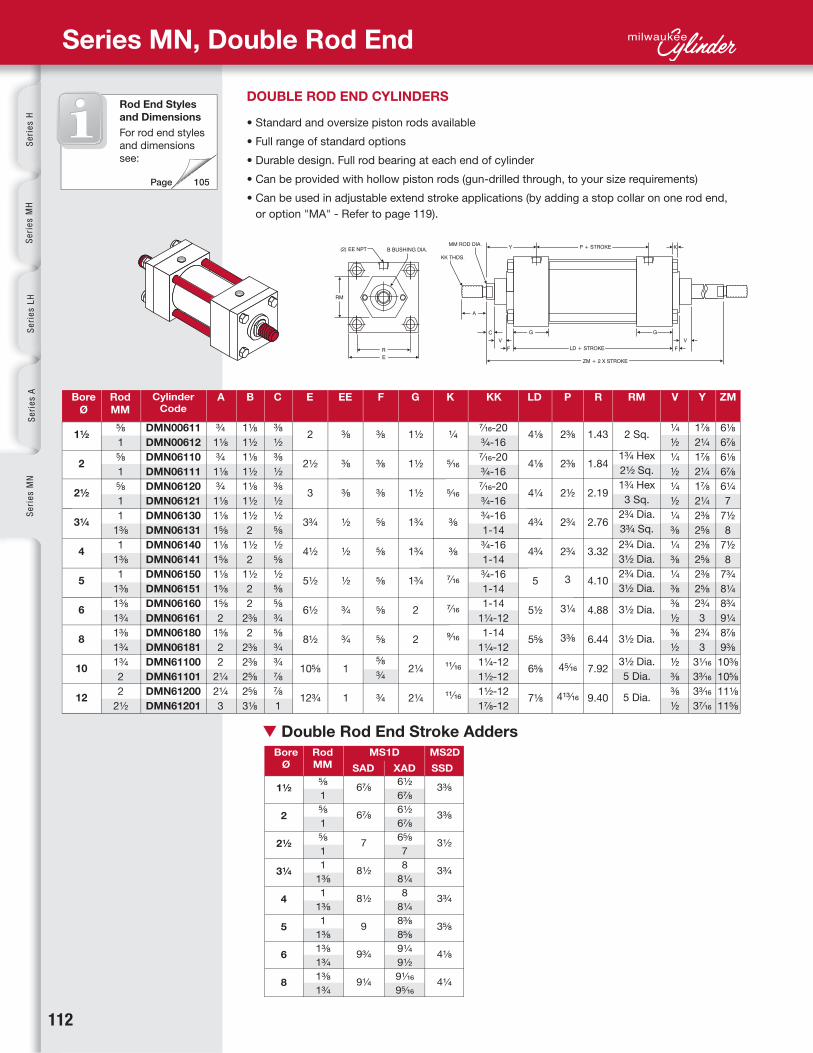
Series MN, Double Rod End
DOUBLE ROD END CYLINDERS
• Standard and oversize piston rods available
• Full range of standard options
• Durable design. Full rod bearing at each end of cylinder
• Can be provided with hollow piston rods (gun-drilled through, to your size requirements)
• Can be used in adjustable extend stroke applications (by adding a stop collar on one rod end,
or option "MA" - Refer to page 119).
Bore
Ø
Bore
Ø
Rod
MM
Rod
MM
Cylinder Code
A B C E EE F G K KK LD P RM
MS1D MS2D
SAD SSDXAD
R YV ZM
▼ Double Rod End Stroke Adders
Rod End Styles
and Dimensions
For rod end styles
and dimensions
see:
1½
2
2½
3¼
4
5
6
8
10
12
1½
2
2½
3¼
4
5
6
8
5�8
1
5�8
1
5�8
1
1
1⅜
1
1⅜
1
1⅜
1⅜
1¾
1⅜
1¾
1¾
2
2
2½
5�8
1
5�8
1
5�8
1
1
1⅜
1
1⅜
1
1⅜
1⅜
1¾
1⅜
1¾
6½
6⅞
6½
6⅞
65�8
7
8
8¼
8
8¼
8⅜
8⅝
9¼
9½
91�16
95⁄16
¾
1⅛
¾
1⅛
¾
1⅛
1⅛
1⅝
1⅛
1⅝
1⅛
1⅝
1⅝
2
1⅝
2
2
2¼
2¼
3
1⅛
1½
1⅛
1½
1⅛
1½
1½
2
1½
2
1½
2
2
2⅜
2
2⅜
2⅜
2⅝
2⅝
3⅛
DMN00611
DMN00612
DMN06110
DMN06111
DMN06120
DMN06121
DMN06130
DMN06131
DMN06140
DMN06141
DMN06150
DMN06151
DMN06160
DMN06161
DMN06180
DMN06181
DMN61100
DMN61101
DMN61200
DMN61201
⅜
½
⅜
½
⅜
½
½
⅝
½
⅝
½
⅝
⅝
¾
⅝
¾
¾
⅞
⅞
1
2
2½
3
3¾
4½
5½
6½
8½
10⅝
12¾
⅜
⅜
⅜
½
½
½
¾
¾
1
1
⅜
⅜
⅜
⅝
⅝
⅝
⅝
⅝
⅝
¾
¾
1½
1½
1½
1¾
1¾
1¾
2
2
2¼
2¼
¼
5�16
5�16
⅜
⅜
7�16
7�16
9�16
11�16
11�16
7⁄16-20
¾-16
7⁄16-20
¾-16
7⁄16-20
¾-16
¾-16
1-14
¾-16
1-14
¾-16
1-14
1-14
1¼-12
1-14
1¼-12
1¼-12
1½-12
1½-12
1⅞-12
4⅛
4⅛
4¼
4¾
4¾
5
5½
5⅝
6⅝
7⅛
67⁄8
6⅞
7
8½
8½
9
9¾
9¼
3⅜
3⅜
3½
3¾
3¾
3⅝
4⅛
4¼
1.43
1.84
2.19
2.76
3.32
4.10
4.88
6.44
7.92
9.40
2⅜
2⅜
2½
2¾
2¾
3
3¼
3⅜
45�16
413�16
2 Sq.
1¾ Hex
2½ Sq.
1¾ Hex
3 Sq.
2¾ Dia.
3¾ Sq.
2¾ Dia.
3½ Dia.
2¾ Dia.
3½ Dia.
3½ Dia.
3½ Dia.
3½ Dia.
5 Dia.
5 Dia.
¼
½
¼
½
¼
½
¼
⅜
¼
⅜
¼
⅜
⅜
½
⅜
½
½
⅜
⅜
½
1⅞
2¼
1⅞
2¼
1⅞
2¼
2⅜
2⅝
2⅜
2⅝
2⅜
2⅝
2¾
3
2¾
3
31�16
33�16
33�16
37�16
6⅛
6⅞
6⅛
6⅞
6¼
7
7½
8
7½
8
7¾
8¼
8¾
9¼
8⅞
9⅜
10⅜
10⅝
11⅛
11⅝

www.milwaukeecylinder.com 113
INDEX TO BASIC OPTIONS
CODE DESCRIPTION
Se
ries
MN
Hyd
-Pn
eu D
evicesC
yl Accessories
Man
ipu
latorsP
ower U
nits/Valves
Desig
n G
uid
e
Basic Option Index
A= EXTENDED PISTON ROD THREAD . . . . . . . . . .
A/O AIR/OIL PISTON . . . . . . . . . . . . . . . . . .
AS ADJUSTABLE STROKE (RETRACT) . . . . . . . . . .
B, BC, BH BUMPERS . . . . . . . . . . . . . . . . . . . . .
BP BUMPER PISTON SEALS . . . . . . . . . . . . . .
H, C, LH, LC, ELH, ELC CUSHIONS . . . . . . . . . . . . . . . . . . . .
ELH, ELC DIMENSIONS FOR EXTRA LONG CUSHIONS . . . . . .
CUSTOM LENGTH CUSHIONS . . . . . . . . . . . .
BSPT/BSPP BRITISH STANDARD PIPE THREADS . . . . . . . . . .
C= EXTENDED PISTON ROD . . . . . . . . . . . . . .
EN ELECTROLESS NICKEL . . . . . . . . . . . . . . .
KK3S STUDDED PISTON ROD . . . . . . . . . . . . . . .
LF LOW FRICTION . . . . . . . . . . . . . . . . . .
MA MIXCRO-ADJUST . . . . . . . . . . . . . . . . .
MAB MICRO-ADJUST WITH URETHANE BUMPER . . . . . .
MPR, MPH MAGNETIC PISTON . . . . . . . . . . . . . . . . .
MS METALLIC ROD SCRAPER . . . . . . . . . . . . .
NR NON-ROTATING (NFPA) CYLINDERS . . . . . . . .
OP OPTIONAL PORT LOCATION . . . . . . . . . . . . .
OPTIONAL PORT & CUSHION AT SAME LOCATION . . .
OS OVERSIZE ROD . . . . . . . . . . . . . . . . . .
SAE SAE "O-RING" BOSS PORTS . . . . . . . . . . .
SSA STAINLESS STEEL "ALL" . . . . . . . . . . . . . .
SSF STAINLESS STEEL FASTENERS . . . . . . . . . . . .
SSR STAINLESS STEEL PISTON ROD . . . . . . . . . . .
SST STAINLESS STEEL TIE RODS & NUTS . . . . . . . .
ST STOP TUBE . . . . . . . . . . . . . . . . . . . .
TH 400 PSI HYDRAULIC (NON SHOCK) . . . . . . . . .
VS VITON . . . . . . . . . . . . . . . . . . . . . .
114
114
114
114
115
116
117
117
118
118
118
118
118
119
119
120
120
120
121
121
121
121
122
122
122
122
122
123
123

114
A=
A/O
AS
B, BC, BH
Se
rie
s H
Se
rie
s M
HS
eri
es
LH
Se
rie
s A
Se
rie
s M
N
MN Basic Options: A=, A/O, AS, B, BC, BH
EXTENDED PISTON ROD THREAD
"A=" Refers to the length of piston rod thread
Shorter than standard lengths can be furnished at no charge. Longer
than standard lengths can be furnished at nominal price adder.
Special length threads available.
AIR/OIL PISTON
Air/Oil pistons allow for the combination of pneumatic supply air
with the precise control of oil.
The basic A/O piston is designed for oil on the cylinder cap end,
and a "meter out" flow control (not provided) for precise return
stroke control.
For applications that require the oil to be on the cylinder rod end,
specify the TH option.
NOTE: Due to the nature of oil to remain in the tubing finish recesses,
a condition called "collaring" will allow oil to seep past the A/O seal
over time, escaping in the air valve exhaust.
ADJUSTABLE STROKE (RETRACT)
Consists of a threaded rod in the cylinder cap, non-removable.
Provides an adjustable positive stop on the cylinder retract.
To order, specify "AS" and length of adjustment (Example: AS=3").
BUMPERS
Urethane impact dampening bumpers, used when cylinder speeds do
not allow for standard cushions.
BC = Cap Bumper BH = Head Bumper B = Head and Cap Bumper
(NOTE: Each bumper adds 1/4" to cylinder length).

www.milwaukeecylinder.com 115
BP
Bumper Piston Seals will shorten the cylinder stroke when operated at less than 90 PSI
supply air. The charts below show the approximate (average) stroke reduction, at various pressure
(for new cylinders). As the cylinders are cycled, the seals will take a slight set. Tests have shown
that after 1,500,000 cycles, the seals will have between .001” and .008” compression set per seal.
After that, there is no noticeable compression set.
TOTAL STROKE REDUCTION ("A" Dimension X 2) (in inches)
PER END STROKE REDUCTION ("A" Dimension) (in inches)
Se
ries
MN
Hyd
-Pn
eu D
evicesC
yl Accessories
Man
ipu
latorsP
ower U
nits/Valves
Desig
n G
uid
e
MN Basic Options: BP
BUMPER PISTON SEALS
Milwaukee Cylinder's Bumper Piston Seal, when used with our advanced
cushion design, decelerates the cylinder at end of stroke — reducing noise and
extending cylinder life.
BENEFITS
• Reduces cycle rates
Higher piston velocities can be achieved
due to rapid deceleration feature
increasing productivity
• Provides maximum impacf dampening
Reduces machine vibration
• Reduces cylinder end-of-stroke noise
• Available in Viton Seals
(1½" to 8" bore)
DESIGN TIPS
• Use cushions to achieve quick performace
on longer strokes (Options HC & BP)
• Use the BP Seals without cushions on
short strokes requiring fast cycles
• Due to compressibility, BP Seals are not
recommended for applications that require
100% repeatable stroke increments
Available on 1½" - 8" Bore1½" Bore Shown
Bore Ø
Bore Ø
0 PSI
0 PSI
10 PSI
10 PSI
30 PSI
30 PSI
50 PSI
50 PSI
70 PSI
70 PSI
90 PSI
90 PSI
Operating Temperature:
-20° F to 200° F
Standard Material: Buna-N
Optional Material: Viton
Operating Temperature:
-150° F to 350° F
Operating Pressure:
250 PSI Air
1½
2
2½
3¼
4
5
6
8
1½
2
2½
3¼
4
5
6
8
.10
.14
.18
.14
.17
.18
.23
.31
.048
.069
.091
.071
.087
.092
.113
.154
.09
.11
.14
.12
.14
.14
.18
.26
.043
.056
.070
.059
.069
.072
.091
.132
.07
.07
.08
.08
.09
.07
.10
.15
.035
.037
.042
.039
.045
.036
.051
.076
.06
.04
.05
.04
.05
.03
.05
.07
.028
.020
.024
.020
.026
.013
.023
.037
.04
.01
.02
.01
.02
.01
.01
.03
.021
.010
.008
.002
.009
.005
.003
.016
.00
.00
.00
.00
.00
.00
.00
.00
.00
.00
.00
.00
.00
.00
.00
.00

116
HOW TO SIZE CUSHIONS FOR YOUR APPLICATION
Cylinders with air cushions provide a possible solution to destructive energies. The air cushion
traps a small amount of exhaust air at the end of stroke, providing an air pocket that decelerates
the load. This reduces the potentially destructive energy being transmitted to the cylinder and other
components. The following is a brief explanation on how to determine the energy level of your
application and determine if an air cushion can provide adequate energy absorption. Air cushions
do not build heat since the heat generated is dissipated with the exhausted air flow.
STEP 1: Determine the total load to be stopped by the cylinder. Include the piston rod weight (see
piston rod weight chart below).
STEP 2: Determine the velocity (in feet per second) at which the load impacts the cylinder end caps.
STEP 3: Use the following formula to calculate the energy the cylinder generates.
STEP 4: Using the table below, select the proper cushion length. Note: You can choose a larger
bore size to increase cushion capacities.
Se
rie
s H
Se
rie
s M
HS
eri
es
LH
Se
rie
s A
Se
rie
s M
N
MN Basic Options: H, LH, ELH, C, LC, ELC
HEAD AND CAP CUSHIONS
Milwaukee Cylinder's advanced cushion design features a unique, one piece seal that is allowed
to float in a precision machined groove.
This type of seal design provides consistent cushion performance and maximum seal life.
Oversized flow paths molded in the periphery of the seal provide “full flow” on the return stroke
without the use of ball checks.
CUSHION SIZING FORMULA
Milwaukee Cylinder's advanced cushion design features a unique, one piece seal that is allowed
to float in a precision machined groove.
energy = ( w x v2) + (p x k)
64
W = Total weight of load in pounds
(including piston rod)
V = Velocity (in feet per second)
P = Driving pressure in PSI
(usually the air line pressure)
K = Bore constant value
(see chart below for “K” values)
How to figure the energy for a 2½" bore cylinder,
10" stroke, 5/8" piston rod, moving a 25 lb. load
at 6 feet per second with 80 psi air.
P = 80 psi W = 26.25 lbs. V = 6 FPS. K = .17
Energy = (26.25/64) X (62) or (36) + (80 X .17)
Energy = 28.36 ft/lbs.
The Maximum Energy Data Chart indicates
that the “Long” Cushion at 38.6 maximum
energy value would be the right choice for this
application.
Front Side Back Side
Seal Design
HEAD CUSHIONS CAP CUSHIONS
STANDARD LENGTH HEAD CUSHION STANDARD LENGTH CAP CUSHION
LONG HEAD CUSHION LONG CAP CUSHION
EXTRA LONG HEAD CUSHION*
* Extra Long Head add length to cylinder.
Refer to page 117 for details.*
* Double weight for double rod end cylinders.
* Extra Long Head add length to cylinder.
Refer to page 117 for details.*
EXTRA LONG CAP CUSHION*
Sizing Example:
H C
LH LC
ELH ELC
Bore
Ø
K
MAXIMUM ENERGY DATA
ELH OR ELC
Extra-Long Cushion Series
Max Energy
(ft-lbs)
LH OR LC
Long Cushion Series
Max Energy
(ft-lbs)
H OR C
Standard Cushion Series
Max Energy
(ft-lbs)
Rod
MMPiston Rod Weight*
Piston Rod Weight Chart
Design Tips
• Cushions
Adjustment screws
can be ordered on
same side as ports. Refer to
page 121 for details.
• BP Seals provide additional
impact dampening and noise
reduction. (Refer to page 145
for details).
1½
2
2½
3¼
4
5
6
8
10
12
.06
.11
.17
.25
.38
.59
1.37
2.43
3.79
5.47
8.2
13.8
24.6
45.7
57.3
94.6
225.5
411.3
379.4
554.8
12.8
21.7
38.6
83.6
137.1
226.0
334.4
609.8
621.4
908.8
26.9
45.8
81.5
172.2
282.6
465.8
767.6
1399.8
1620.9
2370.6
⅝
1
1⅜
1¾
2
2½
.35 lb. + .09 lb/in of stroke
1.1 lb. + .22 lb/in of stroke
2.3 lb. + .42 lb/in of stroke
5.0 lb. + .68 lb/in of stroke
6.1 lb. + .88 lb/in of stroke
10.4 lb. + 1.39 lb/in of stroke

www.milwaukeecylinder.com 117
Se
ries
MN
Hyd
-Pn
eu D
evicesC
yl Accessories
Man
ipu
latorsP
ower U
nits/Valves
Desig
n G
uid
e
Dimensional Data MN Basic Options: ELH, ELC
EXTRA LONG CUSHIONS
Milwaukee Cylinder's “ELH” Extra-Long Head Cushions and “ELC” Extra-Long Cap Cushions
add length to the cylinder. Refer to the chart for dimensions.
EXTRA LONG CUSHIONS
Custom length cushions can be designed for your
application. Contact Milwaukee Cylinder
for details!
Example: An OEM manufacturer of industrial
equipment needed a cylinder to shuttle a 125 lb.
rolling (and guided) fixture 36" of travel, at low
airline pressure to avoid operator injury. A 3½" long
head and cap cushion was designed to meet the
operating specifications.
(MN41-1½" X 6" ELH - EN)
Shown
EXTRA LONG HEAD CUSHION
EXTRA LONG CAP CUSHION
ELH
ELC
Bore
Ø
Rod
MM
Cylinder
Code
A B C E EE F G J K KK LBX PX RMR YV ZBX
1½
2
2½
3¼
4
5
6
8
10
12
5�8
N/A
5�8
1
5�8
1
1
1⅜
1
1⅜
1
1⅜
1⅜
1¾
1⅜
1¾
1¾
2
2
2½
¾
N/A
¾
1⅛
¾
1⅛
1⅛
1⅝
1⅛
1⅝
1⅛
1⅝
1⅝
2
1⅝
2
2
2¼
2¼
3
1⅛
N/A
1⅛
1½
1⅛
1½
1½
2
1½
2
1½
2
2
2⅜
2
2⅜
2⅜
2⅝
2⅝
3⅛
DMN00611
DMN00612
DMN06110
DMN06111
DMN06120
DMN06121
DMN06130
DMN06131
DMN06140
DMN06141
DMN06150
DMN06151
DMN06160
DMN06161
DMN06180
DMN06181
DMN61100
DMN61101
DMN61200
DMN61201
⅜
N/A
⅜
½
⅜
½
½
⅝
½
⅝
½
⅝
⅝
¾
⅝
¾
¾
⅞
⅞
1
2
2½
3
3¾
4½
5½
6½
8½
10⅝
12¾
⅜
⅜
⅜
½
½
½
¾
¾
1
1
⅜
⅜
⅜
⅝
⅝
⅝
⅝
⅝
⅝
¾
¾
1½
1½
1½
1¾
1¾
1¾
2
2
2¼
2¼
1
1
1
1¼
1¼
1¼
1½
1½
2
2
¼
5�16
5�16
⅜
⅜
7�16
7�16
9�16
11�16
11�16
7⁄16-20
N/A
7⁄16-20
¾-16
7⁄16-20
¾-16
¾-16
1-14
¾-16
1-14
¾-16
1-14
1-14
1¼-12
1-14
1¼-12
1¼-12
1½-12
1½-12
1⅞-12
5⅝
5⅝
5¾
6¾
6¾
7
8
8⅛
10⅜
10⅞
1.43
1.84
2.19
2.76
3.32
4.10
4.88
6.44
7.92
9.40
4⅜
4⅜
4½
5¼
5¼
5½
6¼
6⅜
85�16
813�16
2 Sq.
1¾ Hex
2½ Sq.
1¾ Hex
3 Sq.
2¾ Dia.
3¾ Sq.
2¾ Dia.
3½ Dia.
2¾ Dia.
3½ Dia.
3½ Dia.
3½ Dia.
3½ Dia.
5 Dia.
5 Dia.
¼
N/A
¼
½
¼
½
¼
⅜
¼
⅜
¼
⅜
⅜
½
⅜
½
½
⅜
⅜
½
1⅞
N/A
1⅞
2¼
1⅞
2¼
2⅜
2⅝
2⅜
2⅝
2⅜
2⅝
2¾
3
2¾
3
31�16
33�16
33�16
37�16
6⅞
N/A
615/16
75/16
71/16
77⁄16
8½
8¾
8½
8¾
813/16
91⁄16
101⁄16
105⁄16
105⁄16
109�16
1215/16
131⁄16
139⁄16
1013⁄16

118
BSPT
BSPP
KK3S
LF
C=
EN
Se
rie
s H
Se
rie
s M
HS
eri
es
LH
Se
rie
s A
Se
rie
s M
N
MN Basic Options: BSPT, BSPP, C=, EN, KK35, LF
BRITISH STANDARD PIPE TAPER
British Standard Pipe Taper (BSPT) threads have the same taper as American NPT tapered
threads, but use a 55° Whitworth thread form and different diameters. (Not interchangeable
with NPT)
BRITISH STANDARD PIPE PARALLEL
British Standard Pipe Parallel (BSPP) also refered to as BSP "Straight" Thread.
(Not interchangeable with NPT)
STUDDED PISTON ROD
KK3S option combines the KK3 female threaded rod end design and a stud, with permanent
Loctite. When assembled, the KK3S has the same dimensions as a KK1 rod end.
This option is useful in applications that typically break standard KK1 rod ends due to high
load impacting.
LOW FRICTION
“LF” Low Friction option incorporates the use of round-lip, extremely low friction carboxilated
nitrile seals. Round-lip seals “hydroplane” on opposed sealing surfaces, and have a lower
running and break-away friction. • Material: Carboxilated Nitrile • Operating Temperature:
-20°F to 200°F (-25°C to 90°C) • Operating Pressure: 250 psi air (17 bar)
EXTENDED PISTON ROD
"C=" is commonly referred to as Piston Rod Extension. Piston rods can be extended to any
length up to 120" total piston rod length, including stroke portion. Cylinders with long "C"
lengths can be mounted away from obstacles or outside hazardous environments.
ELECTROLESS NICKEL
"EN" or Electroless Nickel plating was invented in 1946, and has gained worldwide
commercial usage since 1964. Common usages include aircraft landing gear, automotive
brake cylinder and components, fuel injector parts, gas turbine parts, spray nozzles for
chemical applications and many electronic devises including hard drives.
The properties of Electroless Nickel contribute to the multitude of uses. The coating
provides an attractive finish, while exhibiting high abrasion and corrosion resistance. Its
ability to uniformly coat blind holes, threads, internal surfaces and sharp edges contributes
to its effectiveness. It has a very high bonding strength to the base metal (100,000-200,000
psi), so much so that gas turbines use electroless nickel plating as a base to braze broken
blades to.
COMMON USAGES:
• FOOD PROCESSING — EN plating has been used to handle such diverse products as sodium
hydroxide, food grade acids and fish oils. Excellent resistance to mild sanitizing caustics,
chlorine, and chlorides in general. The natural smooth finish ensures cleanliness in food
processing equipment.
• PETROLEUM AND CHEMICAL — The petroleum and chemical industry are large users of
electroless nickel plating for corrosion protection. Design tip: Submit the list of chemicals
and concentration levels to Milwaukee Cylinder for evaluation and recommendations. In
some instances, Stainless Steel cylinders provide the best value and long cylinder life.
• MEDICAL AND PHARMACEUTICAL — The medical industry uses EN plated cylinders in clean-
rooms, on equipment used to make plasma or IV bags, since it is critical that cylinder
components need to be sterilized and particle “flake free”. The pharmaceutical industry
typically can be harsh on equipment, even abusive – but the equipment must remain
completely reliable. EN cylinders provide the most reliable and cost effective choice.
Material: Carboxilated Nitrile
Operating Temp.: -20°F to 200°F
Operating Pressure: 250 psi Air
EN CYLINDER SPECIFICATIONS
En Plated Parts:
Tube, Head, Cap, Bushing
Retainer, Mounts (excluding MT1/
MT2 which is hard chrome plated
stainless steel).
Other Components:
303/304 Stainless Steel: Tie Rods
& Nuts, Retainer Screws, Piston
Rod (hard chrome plated), Rod
Bushing with PTFE Wear Band
and Rod Wiper. (Optional: SAE
660 Bronze Rod Bushing)
EN PLATING SPECIFICATIONS:
High Phosphorus (highest
corrosion resistant Electroless
Nickel plating available)
Composition: 87-90% Nickel, 10-
13% Phosphorus
Hardness: Rc 46-48
Thickness: .0005”-.0007”
Lubricity: Excellent (Similar to
chrome)
Coefficent Of Friction: Low
Finish: Bright and very smooth
Other types of EN plating are
available. Contact Milwaukee
Cylinder with your specifications
for a prompt quote.
www.milwaukeecylinder.com 119
MA
MAB
Se
ries
MN
Hyd
-Pn
eu D
evicesC
yl Accessories
Man
ipu
latorsP
ower U
nits/Valves
Desig
n G
uid
e
Dimensional Data MN Basic Options: MA, MAB
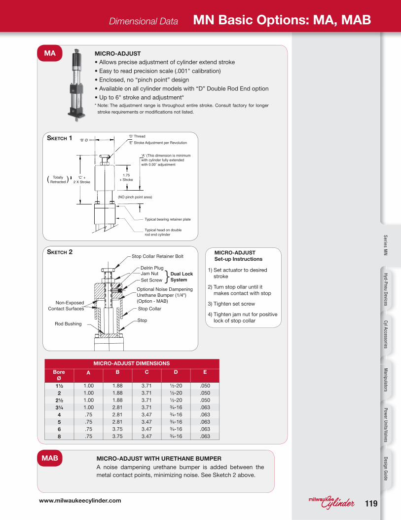
MICRO-ADJUST
• Allows precise adjustment of cylinder extend stroke
• Easy to read precision scale (.001" calibration)
• Enclosed, no “pinch point” design
• Available on all cylinder models with “D” Double Rod End option
• Up to 6" stroke and adjustment*
* Note: The adjustment range is throughout entire stroke. Consult factory for longer
stroke requirements or modifications not listed.
MICRO-ADJUST WITH URETHANE BUMPER
A noise dampening urethane bumper is added between the
metal contact points, minimizing noise. See Sketch 2 above.
MICRO-ADJUST
Set-up Instructions
1) Set actuator to desired
stroke
2) Turn stop ollar until it
makes contact with stop
3) Tighten set screw
4) Tighten jam nut for positive
lock of stop collar
Bore
ØA
MICRO-ADJUST DIMENSIONS
B C D E
SKETCH 1
SKETCH 2
1½
2
2½
3¼
4
5
6
8
1.88
1.88
1.88
2.81
2.81
2.81
3.75
3.75
.050
.050
.050
.063
.063
.063
.063
.063
½ -20
½ -20
½ -20
¾-16
¾-16
¾-16
¾-16
¾-16
1.00
1.00
1.00
1.00
.75
.75
.75
.75
3.71
3.71
3.71
3.71
3.47
3.47
3.47
3.47

120
MPR/MPH
NR
MAGNETIC PISTON
Se
rie
s H
Se
rie
s M
HS
eri
es
LH
Se
rie
s A
Se
rie
s M
N
MN Basic Options: MPR/MPH, MS, NR
MAGNETIC PISTON
MPR Magnetic Pistons are used in conjunction with Milwaukee
Cylinder's R10, R10P, RAC Reed and MSS Solid State Switches.
(See pages 127-133 for switches)
MPH Magnetic Pistons are used with Milwaukee Cylinder's
“Old Style” HE011, HE03SK and HE04SC Hall Effect Switches.
METALLIC ROD SCRAPER
Aggressively scrapes the piston
rod, removing foreign material
such as spatter, sprays and
powders. (Brass contruction)
NON-ROTATING (NFPA) CYLINDERS
2" through 12" bore 200 psi air, 400 psi hydraulic (non-shock)
APPLICATION POSSIBILITIES:
‘NR’ GUIDE ROD SIZES AND MAX. STROKE
Bore
Ø
Rod
MM
Guide Rod
Ø
Max. Stroke
(inches)
Cushions
Benefits:
• Two internal guide rods throughout stroke
• High repeatability at each end of stroke (+/- 1 degree)
• All external dimensions are the same as standard cylinder
(no additional length or width required)
• Standard Diameter Guide Rod Seals & Bronze Bearings for
long life and reliable operation
• Available in Double Rod End Models
Advantages
• Eliminates the need for external guide shafts in many
positioning applications
• Guide rods are internal, self-cleaning, not subjected
to harsh cleaners
• Compact design saves space, no larger than standard
NFPA cylinders!
• Durable, self-contained construction
Note: “NR” option not available in combination with “BP”
bumper piston seal option.
MS
Cap only
Cap only
N/A
Available
Cap only
Available
Available
Available
Available
Available
Available
5�8
5�8
1
1
1⅜
1
1⅜
1
1⅜
1⅜
1¾
1⅜
1¾
1¾
2
2
2½
0.250
0.312
0.312
0.375
0.375
0.625
0.625
0.625
0.625
0.625
0.625
1.000
1.000
1.000
1.000
1.000
1.000
10
12
12
18
18
30
30
30
30
30
30
40
40
40
40
40
40
2
2½
3¼
4
5
6
8
10
12

www.milwaukeecylinder.com 121
OS SAE
OP
1
12
2
3
3
44
BLIND(CAP)
ROD(HEAD)
BASIC DIMENSIONS:
Recommended SAE Port Size by Cylinder Bore
Se
ries
MN
Hyd
-Pn
eu D
evicesC
yl Accessories
Man
ipu
latorsP
ower U
nits/Valves
Desig
n G
uid
e
Dimensional Data MN Basic Options: OP, OS, SAE
OVERSIZE ROD
Applications requiring long strokes may
require oversize piston rod diameters to prevent
sagging or buckling. To determine the recommended rod
diameter, refer to Chart 3 on page 122.
SAE “O”-RING BOSS PORTS (SAE J514)
SAE ports can be ordered in place of NPT
ports. Order by SAE number. (Example SAE#10)
OPTIONAL PORT LOCATION
Optional port locations can be ordered simply by calling out
the location numbers:
Note: When optional port locations are ordered, specify both
port locations, even if one port is in the standard location.
• Standard port positions at 1
• Standard cushion positions at 2
• Specify non-standard locations when ordering
OPTIONAL PORT AND CUSHION AT SAME LOCATION
Now available, the ability to specify Ports and Cushions on the same cylinder side!
Note: When optional port and cushion locations are ordered, specify both port
and cushion locations, even if a port or cushion is in the standard location.
Bore
Ø
Rod
MMFigure A B E EE P Q
Bore Ø SAE# Bore Ø SAE#
5�8
1
5�8
1
5�8
1
1
1⅜
1
1⅜
1
1⅜
1⅜
1¾
1⅜
1¾
1¾
2
2
2½
1
N/A
1
1
1
1
1
2
2
2
2
2
2
2
2
2
2
2
2
2
¾
N/A
⅞
1
1⅛
1⅛
1½
1⅞
2¼
2¼
2¾
2¾
3¼
3¼
4¼
4¼
55/16
55/16
6⅜
6⅜
5�8
N/A
15/16
¾
1⅛
1
1⅜
1
1¼
1⅛
1¾
1⅝
1⅞
1⅞
2¾
2¾
311/16
311/16
4¾
4¾
2
N/A
2½
2½
3
3
3¾
3¾
4½
4½
5½
5½
6½
6½
8½
8½
10⅝
10⅝
12¾
12¾
¼
⅜
⅜
½
½
½
¾
¾
1
1
2⅛
2⅛
2¼
2½
2½
3
3
3⅛
4⅛
4⅝
2⅜
2⅜
2½
2¾
2¾
3
3¼
3⅜
45/16
413/16
1½
2
2½
3¼
4
5
6
8
10
12
1½
2
2½
3¼
4
#4 (7�16-20)
#4 (7�16-20)
#4 (7�16-20)
#6 (9�16-18)
#6 (9�16-18)
#6 (9�16-18)
#8 (¾-16)
#8 (¾-16)
#10 (⅞-14)
#10 (⅞-14)
5
6
8
10
12

122122
SSA
SSR
SSF
SST
Se
rie
s H
Se
rie
s M
HS
eri
es
LH
Se
rie
s A
Se
rie
s M
N
MN Basic Options: SSA, SSF, SSR, SST, ST
STAINLESS STEEL "ALL"
Stainless Steel Piston Rod (Hard-Chrome
Plated), Stainless Steel Fasteners, Stainless
Steel Tie Rods and Nuts
STAINLESS STEEL PISTON ROD
Stainless Steel Piston Rod (Hard-Chrome
Plated)
STAINLESS STEEL FASTENERS
Stainless Steel Fasteners (Bushing Retainer
Screws)
STAINLESS STEEL TIE RODS & NUTS
Stainless Steel Tie Rods and Nuts
STAINLESS STEEL
Stainless Steel, when used in conjunction with Anodized Aluminum Heads, Caps and Tube,
provide corrosion resistance in outdoor applications and wet environments.
Customize your cylinder by choosing from Stainless Steel Fasteners, Piston Rod,
or Tie Rods and Nuts.
STOP TUBE
Stop Tubes are designed to reduce the
piston rod bushing stress to within the designed range
of the bearing material. This will insure proper cylinder
performance, in any given application. Stop Tubes
lower the cylinder bearing stress by adding length to
the piston, which increases the overall length of the
cylinder. (Note: Milwaukee Cylinder uses a double
piston design for 2-inch and longer stop tubes.)
Stop Tube Selection
To determine the proper amount of stop tube for
your application, you must first find the value of “D”,
which represents the “stroke, adjusted for mounting
condition”. Each mounting condition creates different
levels of bushing stress, which have direct impact on
the amount of stop tube required. (See Chart 1)
Once the value of “D” is known, refer to Chart 2 for
the recommended amount of stop tube.
To order a Stop Tube, add the stop tube prefix
“ST=” and the length, to the end of your cylinder
model number.
As noted, the working stroke must be included
when ordering.
ST
HEAD TRUNNIOND=XG + STROKE
CAP CLEVIS OR TRUNNIOND=XC OR XJ + (2 X STROKE)

www.milwaukeecylinder.com 123
TH
VS
Se
ries
MN
Hyd
-Pn
eu D
evicesC
yl Accessories
Man
ipu
latorsP
ower U
nits/Valves
Desig
n G
uid
e
MN Basic Options: TH, VS, WB
400 PSI HYDRAULIC (NON-SHOCK)
“MN” Series can be ordered with the “TH” option.
RATING: 400 PSI Hydraulic, Non-Shock
SEALS:
• Piston Seals - (1) POLY-PAK, (1) square-lip
• Rod Seal - POLY-PAK
VITON SEALS
Benefits of VITON Seals:
• Higher temperature performance (0° F to 350° F [-20° C to 200° C])
• Higher chemical resistance (Resists most wash down solutions)
Many other seal materials are available. Contact Milwaukee Cylinder for proper seal
material selection in tough applications or environments
124
1½ , 2, 2½
3¼ , 4, 5
6 and 8
10
12
CB500
CB750
CB1000
CB1375
CB1750
CB1750
CB1750
EB500
EB750
EB1000
EB1375
EB1750
EB1750
EB1750
(INCLUDES BRIDGE PIN)CLEVIS PIN
MATERIAL: 1018 CRS
FINISH: BLACK OXIDE
HARD CHROME O.D.
(INCLUDES COTTER PINS)CLEVIS PIN
CD + .000/-.001
Se
rie
s H
Se
rie
s M
HS
eri
es
LH
Se
rie
s A
Se
rie
s M
N
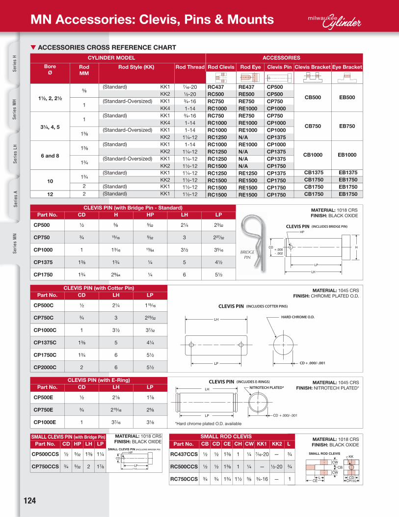
MN Accessories: Clevis, Pins & Mounts
▼ ACCESSORIES CROSS REFERENCE CHART
CYLINDER MODEL ACCESSORIES
Rod
MM
CD
CD
CD
CD CB CHCD CWCE KK1 KK2 LHP LH LP
Part No.
Part No.
Part No.
Part No.Part No.
CLEVIS PIN (with Bridge Pin - Standard)
CLEVIS PIN (with Cotter Pin)
CLEVIS PIN (with E-Ring)
SMALL ROD CLEVISSMALL CLEVIS PIN (with Bridge Pin)
Rod Style (KK)
H
Rod Thread
HP
Rod Clevis
LH
LH
LH
Rod Eye
LP
LP
LP
Clevis Pin Clevis Bracket Eye Bracket
MATERIAL: 1018 CRS
FINISH: BLACK OXIDE
MATERIAL: 1045 CRS
FINISH: CHROME PLATED O.D.
MATERIAL: 1045 CRS
FINISH: NITROTECH PLATED*
MATERIAL: 1018 CRS
FINISH: BLACK OXIDE
Bore
Ø
RC437
RC500
RC750
RC1000
RC750
RC1000
RC1000
RC1250
RC1000
RC1250
RC1250
RC1500
RC1250
RC1500
RC1500
RC1500
CP500
CP750
CP1000
CP1375
CP1750
CP500C
CP750C
CP1000C
CP1375C
CP1750C
CP2000C
CP500E
CP750E
CP1000E
RC437CCS
RC500CCS
RC750CCS
CP500CCS
CP750CCS
½
¾
1
1⅜
1¾
½
¾
1
1⅜
1¾
2
½
¾
1
½
½
¾
½
½
¾
1⅜
1⅜
1¾
1
1
1½
¼
¼
⅜
7⁄16-20
—
¾-16
—
½-20
—
¾
¾
1
½
¾
5�32
5�32
1⅜
2
1¼
1⅞
⅝
15�16
13�16
1¾
29⁄64
5�32
5�32
13�64
¼
¼
2¼
3
3½
5
6
2¼
3
3½
5
6
6
2⅛
215�16
37�16
23�32
227�32
35�16
4½
5½
115�16
223�32
37�32
4¼
5½
5½
1⅞
2⅝
3⅛
CP500
CP500
CP750
CP1000
CP750
CP1000
CP1000
CP1375
CP1000
CP1375
CP1375
CP1750
CP1375
CP1750
CP1750
CP1750
RE437
RE500
RE750
RE1000
RE750
RE1000
RE1000
N/A
RE1000
N/A
N/A
N/A
RE1250
RE1500
RE1500
RE1500
⅝
1
1
1⅜
1⅜
1¾
1¾
2
2
7⁄16-20
½-20
¾-16
1-14
¾-16
1-14
1-14
1¼-12
1-14
1¼-12
1¼-12
1½-12
1¼-12
1½-12
1½-12
1½-12
(Standard) KK1
KK2
(Standard-Oversized) KK1
KK4
(Standard) KK1
KK4
(Standard-Oversized) KK1
KK2
(Standard) KK1
KK2
(Standard-Oversized) KK1
KK2
(Standard) KK1
KK2
(Standard) KK1
(Standard) KK1
NITROTECH PLATED*(INCLUDES E-RINGS)CLEVIS PIN
*Hard chrome plated O.D. available

www.milwaukeecylinder.com 125
Se
ries
MN
Hyd
-Pn
eu D
evicesC
yl Accessories
Man
ipu
latorsP
ower U
nits/Valves
Desig
n G
uid
e
ROD CLEVIS
ROD EYE
CLEVIS BRACKET
EYE BRACKET
MN Accessories: Clevis, Pins & Mounts
Part No.
Part No.
Part No.
Part No.
CB
A
BA
BA
CB
CB
CD
CD
CW
DD
DD E
E
F
F
FL
FL
L
L
M
M
CD
CA
CE
CB
CH
CD
CW
ER
ER
KK
KK LMATERIAL: CAST STEEL
FINISH: BLACK OXIDE
MATERIAL: 1018 CRS
FINISH: BLACK OXIDE
MATERIAL: CAST STEEL
FINISH: BLACK OXIDE
MATERIAL: CAST STEEL
FINISH: BLACK OXIDE
¾
¾
1¼
1½
2
2
2½
2½
2½
¾
¾
1⅛
1⅝
2
2¼
1⅝
29�16
3¼
313�16
415�16
1⅝
29�16
3¼
313�16
4.95
⅜
⅝
¾
⅞
⅞
⅜
⅝
¾
⅞
⅞
2½
3½
4½
5
6½
2½
3½
4½
5
6½
½
½
¾
1
1⅜
1⅜
1¾
1¾
2
7�16-20
½-20
¾-16
1-14
1¼-12
1½-12
⅜-24
½-20
⅝-18
⅝-18
⅞-14
13�32
17�32
21�32
21�32
29�32
½
½
¾
1
1⅜
1⅜
1¾
1¾
2
1½
1½
21�16
213�16
37�16
4
¾
1¼
1½
2
2½
¾
1¼
1½
2
2½
1⅛
1⅞
2¼
3
3⅛
1⅛
1⅞
2¼
3
3⅛
½
½
⅝
¾
1
1
1¼
1¼
1¼
⅝
⅝
⅞
13�16
19�16
2
¾
¾
1¼
1½
2⅛
2⅛
2¼
2¼
2½
7�16-20
½-20
¾-16
1-14
1¼-12
1⅜-12
1½-12
1¾-12
17�8-12
1½
1½
2⅜
3⅛
4⅛
4⅛
4½
4½
5½
¾
¾
1¼
1½
2
2½
½
¾
1
1⅜
1¾
½
¾
1
1⅜
1¾
¾
1¼
1½
2⅛
2¼
¾
1¼
1½
2⅛
2¼
1
1
1¼
1½
2
2
2⅜
2⅜
3
½
½
¾
1
1⅜
1¾
½
⅝
¾
1
1¼
⅝
¾
1
1⅜
1¾
½
¾
1
1⅜
1¾
RC437
RC500
RC750
RC1000
RC1250
RC1375
RC1500
RC1750
RC1875
RE437
RE500
RE750
RE1000
RE1250
RE1500
CB500
CB750
CB1000
CB1375
CB1750
EB500
EB750
EB1000
EB1375
EB1750

126 www.milwaukeecylinder.com
1½ , 2, 2½
3¼ , 4, 5
6 and 8
EY
E B
RA
CK
ET
SC
LE
VIS
BR
AC
KE
TS
Se
rie
s H
Se
rie
s M
HS
eri
es
LH
Se
rie
s A
Se
rie
s M
N
▼ STAINLESS STEEL ACCESSORIES CROSS REFERENCE CHART
▼ ACCESSORIES (303 Stainless Steel)
CYLINDER MODEL ACCESSORIES
Rod
MM
CD
CB
A
BA CB CD CW DD E F FL L M
CD
CA
CE
CB
CW
CD
ER
ER
KK
KK
L
Part No.
Part No.
Part No.
Part No.
CLEVIS PIN (with Cotter Pins)
ROD CLEVIS
ROD EYE
CLEVIS BRACKETS AND EYE BRACKETS
Rod Style (KK) Rod Thread Rod Clevis
LH
Rod Eye
LP
Clevis Pin Clevis Bracket Eye Bracket
MN Accessories: Stainless Steel Clevis, Pins & Mounts
Bore
Ø
SS-RC437
SS-RC500
SS-RC750
SS-RC1000
SS-RC750
SS-RC1000
SS-RC1000
SS-RC1250
SS-RC1000
SS-RC1250
SS-RC1250
SS-RC1500
SS-CP500
SS-CP750
SS-CP1000
SS-CP1375
SS-CP1750
SS-RC437
SS-RC500
SS-RC750
SS-RC1000
SS-RC1250
SS-RC1500
SS-RE437
SS-RE500
SS-RE750
SS-RE1000
SS-RE1250
SS-RE1500
SS-CB500
SS-CB750
SS-CB1000
SS-EB500
SS-EB750
SS-EB1000
½
¾
1
1⅜
1¾
¾
¾
1¼
1½
2
2½
¾
¾
1⅛
1⅝
2
2¼
½
⅝
¾
N/A
½
¾
1
½
¾
1
¾
¾
1¼
1½
2⅛
2¼
¾
¾
1¼
1½
2
2½
¾
1¼
1½
¾
1¼
1½
¾
1¼
1½
¾
1¼
1½
1⅛
1⅞
2¼
1⅛
1⅞
2¼
½
½
⅝
¼
1
1¼
½
½
¾
1
1⅜
1¾
⅜
⅝
¾
⅜
⅝
¾
½
½
¾
1
1⅜
1¾
1½
1½
21�16
213�16
37�16
4
1⅝
29�16
3¼
1⅝
29�16
3¼
2½
3½
4½
2½
3½
4½
1½
1½
2⅜
3⅛
4⅛
4½
2¼
3
3½
5
6
½
½
¾
1
1⅜
1¾
⅝
⅝
⅞
13�16
19�16
2
⅝
¾
1
½
¾
1
115⁄16
223�32
37�32
4¼
5½
SS-CP500
SS-CP500
SS-CP750
SS-CP1000
SS-CP750
SS-CP1000
SS-CP1000
SS-CP1375
SS-CP1000
SS-CP1375
SS-CP1375
SS-CP1750
SS-RE437
SS-RE500
SS-RE750
SS-RE1000
SS-RE750
SS-RE1000
SS-RE1000
N/A
SS-RE1000
N/A
N/A
N/A
⅝
1
1
1⅜
1⅜
1¾
7⁄16-20
½-20
¾-16
1-14
¾-16
1-14
1-14
1¼-12
1-14
1¼-12
1¼-12
1½-12
(Standard) KK1
KK2
(Standard-Oversized) KK1
KK4
(Standard) KK1
KK4
(Standard-Oversized) KK1
KK2
(Standard) KK1
KK2
(Standard-Oversized) KK1
KK2
SS-CB500
SS-CB750
SS-CB1000
SS-EB500
SS-EB750
SS-EB1000
7�16-20
½-20
¾-16
1-14
1¼-12
1½-12
7�16-20
½-20
¾-16
1-14
1¼-12
1½-12
⅜-24
½-20
⅝-18
13�32
17�32
21�32

127 *Use resistor-capacitor protection **Minimum current = 80mA
R10 R10P MSS
RAC
Se
ries
MN
Hyd
-Pn
eu D
evicesC
yl Accessories
Man
ipu
latorsP
ower U
nits/Valves
Desig
n G
uid
e
▼ SWITCH APPLICATION SELECTION GUIDE For selecting the right switch for your application
MN Accessories: R10, R10P, RAC, MSS Switches
Milwaukee Cylinder offers Reed, High Power AC Reed, DC Solid State and Reed Switches
with built-in circuit protection to meet a wide variety of customer needs.
Advantages:
• Compact low profile switch/bracket
assembly
• Switches and brackets are nylon and
stainless steel hardware construction
– suitable for wash down or corrosive
environments (IP67)
• Quick, simple set-up: Requires
standard (slotted) screw driver only
• High visibility LED can be seen up to
20 feet
• Optional quick connect threaded
coupling on low current model
• Magnetically operated, can be located
anywhere in the actuator stroke range
• Can be used with the MN Series
Milwaukee Cylinder aluminum
actuators, electroless nickel plated
series, and stainless steel
(Note: Specify “MPR” option when
ordering actuator)
• Suitable for all bore sizes (1½" to 12")
• One magnet (MPR) for all switch
models
Benefits of REED Switch:
• Internal circuit protection
• Lower cost
• Low or high current models available,
AC or DC, and TRIAC type switch for
inductive loads
• High visibility red LED (on low current
models)
• Choice of lead lengths available on all
models
• Optional quick connect threaded
coupling on low current model
Benefits of SOLID STATE Switch:
• Faster signal speeds
• Solid State Reliability – No moving
parts means long life,
no contact bounce or wear
• Reverse Polarity and Over Voltage
Protection
• High Visibility Red LED
(all models)
• Choice of lead lengths available or
Quick Connect Threaded Coupling
Switch Model Programmable
Controllers
Relays Indicator Lights
Bulbs
MotorsSolenoids
Solid State
Time
Counters
Minature REED Switch
• 5-120 Volts AC, 5-110 Volts DC,
400 mA current rating (max.)
• Cable options include 24" or 120" plain cable
leads, and 8mm threaded quick connect
• High visibility LED
Miniature AC/DC REED Switch with built-in Circuit Protection
• 5-120 Volts AC, 5-110 Volts DC, 150 mA
current rating (max.)
• Cable options include 24" or 120" plain cable leads
• High visibility LED
• Circuit protection consisting of varistor/choke
arrangement that will protect switch from transients,
voltage spikes and inrush currents usually
associated with long cable runs (particularly at
higher voltages) and unprotected inductive loads
such as relays, solenoids, motors, and motor
starters and some PLC’s
Minature SOLID
STATE Switch
• 10-30 Volts DC, 4-300 mA
current rating
• Can be wired current sinking
(NPN) or current sourcing (PNP)
• Cable options include 24" or
120" plain cable leads, and
8mm threaded quick connect
• High visibility LED
High Power AC REED Switch
• 12-240 Volts AC, 800 mA current
rating, TRIAC output
• Cable options include 24" or 120" plain
cable leads
SWITCHES
■ Miniature AC/DC Reed
■ High Power AC Reed
■ CE RoHS
■ Miniature AC/DC Reed with built-in Circuit Protection
■ Extended Temperature Range Reed
■ Miniature DC Solid State
R10 Reed
RAC High
Powered Reed**
R10P Reed
MSS Solid State
Yes
No
Yes
Yes
<10VA*
Yes
<10VA
<300mA
<10VA*
Yes
<10VA
<300mA
<10VA*
Yes
<10VA
<300mA
Yes
No
No
Yes
<10VA*
Yes
<10VA
No
<10VA*
Yes
<10VA
No

128
Se
rie
s H
Se
rie
s M
HS
eri
es
LH
Se
rie
s A
Se
rie
s M
N
MN Accessories: Switches — REED
MINATURE REED SWITCH, CABLE TYPE, (Two Wire Switch)
R10: Miniature Reed Switch, 24" Plain Cable Lead, (2 wire Switch)
R10X: Miniature Reed Switch, 120" Plain Cable Lead, (2 wire Switch)
Contacts: SPST Form A (Normally Open)
Contact Rating: 10 Watts Max.
Input Voltage: 5-120 Volts Max. AC, 5-110 Volts Max. DC
Maximum Load Current: 400 mA Max. (Resistive) @ 25° C (77° F)
150 mA Max. (Resistive) @ 70° C (158° F)
Actuating Time Average: 1.0 millisecond
LED Indicator: High Luminescence Housing
Temperature Range: -20° C to 70° C (-4° F to 158° F)
Protection Rating: IP67
MINIATURE REED SWITCH, 24" PLAIN CABLE LEAD, CIRCUIT PROTECTION,
(Two Wire Switch)
R10P: Miniature Reed Switch, 24” Plain Cable Lead,
Circuit Protection (2 wire Switch)
R10PX: Miniature Reed Switch, 120” Plain Cable Lead,
Circuit Protection (2 wire Switch)
Contacts: SPST Form A (Normally Open)
Contact Rating: 10 Watts Max.
Input Voltage: 5-120 Volts Max. AC, 110 Volts Max. DC
Maximum Load Current: 150 mA Max. (Resistive)
Actuating Time Average: 1.0 millisecond
LED Indicator: High Luminescence Housing
Temperature Range: -20° C to 70° C (-4° F to 158° F)
Protection Rating: IP67
MINATURE REED SWITCH, 8mm MALE QUICK CONNECT, (Two Wire Switch)
R10Q: Miniature Reed Switch, 8mm Male Quick Connect, (2 wire Switch)
Contacts: SPST Form A (Normally Open)
Contact Rating: 10 Watts Max.
Input Voltage: 60 Volts Max. AC or DC
Maximum Load Current: 400 mA Max. (Resistive) @ 25° C (77° F)
150 mA Max. (Resistive) @ 70° C (158° F)
Actuating Time Average: 1.0 millisecond
LED Indicator: High Luminescence Housing
Temperature Range: -20° C to 70° C (-4° F to 158° F)
Protection Rating: IP67
LOAD CURRENT DE-RATING GRAPH
R10 / R10X / R10Q
(R10PX: 150 mA MAX., -20°C to 70°C)
HIGH POWER AC REED SWITCH, CABLE TYPE, (Two Wire Switch)
RAC: High Power AC Reed Switch, 24” Plain Cable Lead, (2 wire Switch)
RACX: High Power AC Reed Switch, 120” Plain Cable Lead, (2 wire Switch)
Contacts: TRIAC Output
Contact Rating: 200 Watts Max.
Input Voltage: 12 to 240 Volts (AC only)
Minimum Load Current: 80 mA
Maximum Load Current: 800 mA
Actuating Time Average: 2.0 milliseconds
LED Indicator: Not Available
Temperature Range: -20° C to 70° C (-4° F to 158° F)
Protection Rating: IP67
Input Voltage: 110 Volts Max. DC, 120 Volts Max. AC
Maximum Load Current: 400 mA Max. (Resistive) @ 25° C (77° F)
150 mA Max. (Resistive) @ 70° C (158° F)
Input Voltage: 120 Volts Max. AC, 110 Volts Max. DC
Maximum Load Current: 150 mA Max.
Circuit Protection
Varistor: 138 Volts
Choke: 680 μH
Input Voltage: 60 Volts Max. AC or DC
Maximum Load Current: 400 mA Max. (Resistive) @ 25° C (77° F)
150 mA Max. (Resistive) @ 70° C (158° F)
Contact Rating 200 Watts Max.
Input Voltage 12 to 240 Volts (AC only)
Minimum Load Current 80 mA
Maximum Load Current 800 mA
R10 / R10X
R10P/R10PX
R10Q
RAC / RACX
Note: The circuit protection consists of a Varistor and Choke arrangement. The Varistor will take transient and voltage spikes out of the line and is mounted in parallel with the switch. The Choke will disperse inrush currents (normally caused by long cable runs) and is mounted in series with the switch.

www.milwaukeecylinder.com 129
Se
ries
MN
Hyd
-Pn
eu D
evicesC
yl Accessories
Man
ipu
latorsP
ower U
nits/Valves
Desig
n G
uid
e
MN Accessories: Switches — SOLID STATE/HALL EFFECT
MINATURE SOLID STATE SWITCH, CABLE TYPE, (Two Wire Switch)
MSS: Miniature Solid State Switch, 24" Plain Cable Lead, (2 wire Switch)
MSSX: Miniature Solid State Switch,120" Plain Cable Lead, (2 wire Switch)
*Output Type: Current Sinking or Current Sourcing
Input Voltage: 10 to 30 Volts DC
Current Consumption: (not sensing): 1mA
Minimum Load Current: 4 mA
Maximum Load Current: 300 mA
“ON” Voltage Drop: 3 Volts @ 4 mA
4 Volts @ 300 mA
LED Indicator: High Luminescence Housing
Temperature Range: -20° C to 70° C
(-4° F to 158° F)
Actuating Time Average: 2.0 Microseconds
Protection Rating: IP67
Reverse Polarity Protected: Yes
Transient (over voltage) Protected: Yes
MINIATURE SOLID STATE SWITCH, 8mm MALE QUICK CONNECT,
(Two Wire Switch)
MSSQ: Miniature Solid State Switch,
8mm Male Quick Connect
(2 wire Switch)
*Output Type: Current Sinking or Current Sourcing
Input Voltage: 10 to 30 Volts DC
Current Consumption (not sensing): 1mA
Minimum Load Current: 4 mA
Maximum Load Current: 300 mA
“ON” Voltage Drop: 3 Volts @ 4 mA
4 Volts @ 300 mA
LED Indicator: High Luminescence Housing
Temperature Range: -20° C to 70° C
(-4° F to 158° F)
Actuating Time Average: 2.0 Microseconds
Protection Rating: IP67
Reverse Polarity Protected: Yes
Transient (over voltage) Protected: Yes
*NOTE: This is a (2) wire switch used in series with the load. Therefore, this switch can be used with devices requiring either a current sinking (NPN) output or a current sourcing (PNP) output from the solid state switch.
*NOTE: This is a (2) wire switch used in series with the load. Therefore, this switch can be used with devices requiring either a current sinking (NPN) output or a current sourcing (PNP) output from the solid state switch.
MSS / MSSX
MSSQ
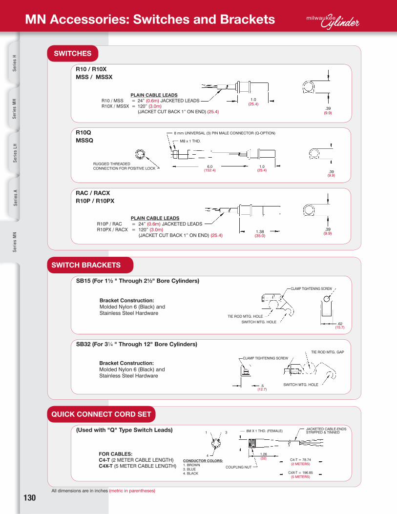
130All dimensions are in inches (metric in parentheses)
Se
rie
s H
Se
rie
s M
HS
eri
es
LH
Se
rie
s A
Se
rie
s M
N
MN Accessories: Switches and Brackets
SWITCHES
SWITCH BRACKETS
QUICK CONNECT CORD SET
R10 / R10X
MSS / MSSX
SB15 (For 1½ " Through 2½" Bore Cylinders)
(Used with "Q" Type Switch Leads)
R10Q
MSSQ
SB32 (For 3¼ " Through 12" Bore Cylinders)
RAC / RACX
R10P / R10PX

www.milwaukeecylinder.com 131
Se
ries
MN
Hyd
-Pn
eu D
evicesC
yl Accessories
Man
ipu
latorsP
ower U
nits/Valves
Desig
n G
uid
e
MN Accessories: Switch Mounting
SB15 / SB32
SB15
SB32
A B C D E GBore ØPart #
▼ SWITCH BORE DIMENSIONAL TABLE
▼ HOW TO ASSEMBLE SWITCH AND BRACKETS
Recommended Torque:
6-10 in-lbs.
(Do not exceed 14 in-lbs)
* These dimensions are 1/2 of the 'C' dimension. The switch barcket does not protrude beyond standard head/cap.
Recommended Torque:
8-12 in-lbs.
(Do not exceed 14 in-lbs)
SB
32
SB
15 1½
2
2½
3¼
4
5
6
8
10
12
113�32
121�32
1⅞
2⅛
2⅜
2¾*
3¼*
4¼*
55/16*
6⅜*
⅝
⅝
⅝
½
½
½
½
½
½
½
½
½
½
9⁄16
9⁄16
9⁄16
9⁄16
9⁄16
9⁄16
9⁄16
¼
5⁄16
5⁄16
⅜
⅜
½
½
⅝
¾
¾
1⅜
1⅝
17/8
2⅛
27/16
2⅞
3¼*
4¼*
55/16*
6⅜*
2
2½
3
3¾
4½
5½
6½
8½
10⅝
12¾

132
R10P / R10PX
RAC / RACX
MSS / MSSX / MSSQ
NOTE: Dimensions are in inches, (metric in parentheses). Results are based upon Milwaukee Cylinder's piston and magnet
assemblies. Results may vary if used with other manufacturers cylinder products.
R10 / R10X / R10Q
Se
rie
s H
Se
rie
s M
HS
eri
es
LH
Se
rie
s A
Se
rie
s M
N
MN Accessories: Switches Hysteresis & Band Width
HYSTERESIS:
The distance between the switch break point moving in one direction, and the switch make
point moving in the opposite direction.
BAND WIDTH:
Distance the piston moves while the switch is made (in either direction), less the hysteresis.
Hysteresis
(Maximum)
Band Width
(Minimum)
Repeatability
Hysteresis
(Maximum)
Band Width
(Minimum)
Repeatability
Hysteresis
(Maximum)
Band Width
(Minimum)
Repeatability
Hysteresis
(Maximum)
Band Width
(Minimum)
Repeatability
±.010" (±,25 mm) .040" (1 mm) .200" (5 mm)
±.010" (±0,25 mm) .040" (1 mm) .200" (5 mm)
±.010" (±0,25 mm) .085" (2,1 mm) .345" (8,8 mm)
±.010" (±0,25 mm) .075" (1,9 mm) .315" (8 mm)

www.milwaukeecylinder.com 133
R10 SB15XSwitch Model Switch Bracket SizeSwitch Lead Type
▼ CONFIGURE YOUR SWITCH PART NUMBER
-
Se
ries
MN
Hyd
-Pn
eu D
evicesC
yl Accessories
Man
ipu
latorsP
ower U
nits/Valves
Desig
n G
uid
e
MN Accessories: Switch Ordering Instructions
ABOUT OUR SWITCHES
Our switches are different! The most common complaint in the market is the unreliability of
magnetically operated switches. Most cylinder piston magnets have about 10-30% more power
than required to operate the switch. This results in erractic operation, a nuisance for maintenance
and lowering overall plant productivity.
Milwaukee Cylinder's magnets have 50-100% more power than required to operate our switch!
The combination of Milwaukee Cylinder's R10, R10P, RAC and MSS Switches and our Cylinders,
raises the reliability of switch operation comparable to that of many mechanically operated
limit switches.
APPLICATION RECOMMENDATIONS AND PRECAUTIONS
• Noise suppression — Motors and valve solenoids will produce high pulses throughout an
electrical system. Therefore, primary and control circuit wiring should not be mixed in the same
conduit. Separate power supplies for both logic level signals (Microprocessor, P.C., CPU, Input
Devices) and Output Field Devices (Motors, Valve Solenoids) is recommended.
• Never connect R10, R10P or MSS type switches without a load present. The switch will
be destroyed.
• Some electrical loads may be capacitive. Capacitive loading may occur due to distributed
capacity in cable runs over 25 feet. Use switch model RAC whenever capacitive loading
may occur.
• To obtain optimum performace and long life, switches should not be subjected to strong
magnetic fields, extreme temperatures (outside of specifications), or excessive ferrous filings
or chip buildup.
• Improper wiring may damage or destroy the switch. Therefore, the wiring diagrams along with
the listed power ratings, should be carefully observed before connecting power to the switch.
Following these tips can save time and provide trouble free installations!
TO ORDER, SPECIFY:
Switch Model, Lead Type,
and Bracket Size
Switch Model
Model Description
Switch Lead Type Switch Bracket Size
Quick Connect Cord Sets
R10 = AC/DC Reed
RAC = High Power AC Reed
MSS = Solid State
R10P = AC/DC Reed with Circuit
Protection
(leave blank) = 24" Plain Cable
X = 120" Plain Cable
Q = 8mm Quick Connect
(not available on RAC
or R10P)
SB15 = 1½” to 2½” Bore
SB32 = 3¼” to 12” Bore
(leave blank for switch only)
C4-T 8mm Straight Quick Connect Cord X 2 Meter (78")
C4X-T 8mm Straight Quick Connect Cord X 5 Meter (196")
Other switches available:
• 12mm Quick Connect
• Pulse Extension Switch
• Special Length Cable
• Change Over Switch (SPDT)
• Weld Immune Switch
• High Temp. Switch
(Consult factory for details.)
▼ SWITCH ACCESSORIES

134
MN06130 14¾HC31 7KK2 x- - - -
▼ CONFIGURE YOUR CYLINDER (Series MN cylinder)
Cylinder Code CushionsNFPA MountsDouble Rod End
add "D"Options Seals Stroke
Part Number System
Example: A 3¼" Bore, 1" rod,
MF1 mount, cushion both ends,
Style KK2 rod end, standard seals
with a 14¾" stroke.
Part Number:
MN06130-31-HC-KK2-7 x 14¾
1
12
2
3
3
44
BLIND(CAP)
ROD(HEAD)
Se
rie
s H
Se
rie
s M
HS
eri
es
LH
Se
rie
s A
Se
rie
s M
N
Bore Ø
Bore Ø
B
OPTION
BC BH ELC ELH
ST* (Stop Tube)
Example: ST=2
Rod Ø Cylinder Code
Description
Add length to cylinder - See "Option Length Adder" Chart Below
Description
11/2
2
21/2
3¼
4
5
6
8
10
12
11/2
2
21/2
3¼
4
5
6
8
10
12
1/2
1/2
1/2
1/2
1/2
1/2
1/2
1/2
1/2
1/2
BUNA (-30° to 250° F)
VITON (-15° to 350° F)
SPECIAL
7
8
S
0" to 120" / Made to order.
¼
¼
¼
¼
¼
¼
¼
¼
¼
¼
¼
¼
¼
¼
¼
¼
¼
¼
¼
¼
1
1
1
1¼
1¼
1¼
11/2
11/2
2
2
1
1
1
1¼
1¼
1¼
11/2
11/2
2
2
2
2
2
2
2
2
2
2
2
2
H
LH
ELH
C
LC
ELC
NC
5/8
1
5/8
1
5/8
1
1
13/8
1
13/8
1
13/8
13/8
1¾
13/8
1¾
1¾
2
2
2½
MF1
MF2
ME3
ME4
MP1
MP2
MP4
MS1
MS2
MS4
MT1
MT2
MT4
MX0
MX1
MX2
MX3
KK1
A =
AS
A/O
*B
*BC
*BH
BP
BSPP
BSPT
C =
EN
KK2
KK3
KK3S
KK4
KK5
LF
MA
MAB
MPR
MPH
MS
NR
OP
OS
SAE
SE
SR
SSA
SSF
SSR
SST
*ST
Steel tube
TH
XX
31
32
21
22
61
63
64
44
42
41
71
72
74
11
10
13
12
Head CushionPosition 2 is StandardSpecify for Positions: 1, 3 & 4
Long Head CushionPosition 2 is StandardSpecify For Positions: 1, 3 & 4
Extra Long Head CushionPosition 2 is StandardSpecify for Positions: 1, 3 & 4
Cap CushionPosition 2 is StandardSpecify for Positions: 1, 3 & 4
Long Cap CushionPosition 2 is StandardSpecify for Positions: 1, 3 & 4
Extra Long Cap CushionPosition 2 is StandardSpecify for Positions: 1, 3 & 4
No Cushion
2 CYLINDER CODE
4 CUSHIONS
3 NFPA MOUNTS
5 OPTIONS
OPTIONS LENGTH ADDER (add to catalog basic overall length dimensions.
6 SEALS
7 STROKE
Standard
Extended piston rod thread (Example: A = 2")
Adjustable stroke - retract (specify length, example: AS = 4")
Air / oil piston
¼" Urethane bumper both ends
¼" Urethane bumper cap only
¼" Urethane bumper head only
Bumper piston seals (1½" - 8" bore)
BSPP ports (specify size, example: BSPP = ¼")
BSPT ports (specify size, example: BSPT = ¼")
Extended piston rod (example: C = 3")
Electroless nickel plated (see page 118 for specifications)
Large male rod thread
Female rod thread
Studded piston rod (KK3 with stud, loctite in place)
Full diameter male rod thread
Blank rod end (no threads, “A” = 0”)
Low friction seals (see page 118 for specifications)
Micro-adjust (6" max. stroke) available on double rod end models
Micro-adjust with sound dampening bumper (6" max. stroke)
Magnetic piston for Reed or Solid State switches R10, RAC,
and MSS (see pages 127-133 for selection)
Magnetic piston for hall switches
Metallic rod scraper (brass construction)
Non-rotating (see page120 for specifications)
Optional port location (example: ports at 2 and 3)
Oversize rod diameter (specify size, example: OS = 1⅜")
Sae ports (specify size, example: SAE #10)
Spring extend (1½, 2, 2½ inch bore)
Spring return (1½, 2, 2½ inch bore)
Stainless steel piston rod, tie rods & nuts, and fasteners
Stainless steel fasteners
Stainless steel piston rod
Stainless steel tie rods & nuts
Stop tube (specify stop tube length and effective stroke) (example: MN MS4 2 x 24" effective stroke-ST=3)
Steel cylinder tube, black epoxy paint finish
400 psi hydraulic non-shock (see page 123 for specifications)
Special variation (specify)
* Add length to cylinder - See "Options Length Adder" chart below
2 31 4 5 6 7
Series MN Ordering Guide
Front Flange (1½"-6" Bore)
Rear Flange (1½"-6" Bore)
Front Mounting Holes (8"-12" Bore)
Rear Mounting Holes (8"-12" Bore)
Rear Pivot Clevis (1½"-12" Bore)
Rear Pivot Clevis, Removable (1½"-6" Bore)
Rear Fixed Eye Mount, Removable (1½"-6" Bore)
Front & Rear End Angle (1½"-8" Bore)
Side Lug (1½"-8" Bore)
Bottom Tapped Holes (1½ -12" Bore)
Front Trunnion (1½"-8" Bore)
Rear Trunnion (1½"-8" Bore)
Intermediate Trunnion (1½"-8" Bore)
No Mount (1½"-12" Bore)
Extended Tie Rods - Head & Cap (1½"-12" Bore)
Extended Tie Rods (Cap) (1½"-12" Bore)
Extended Tie Rods (Head) (1½"-12" Bore)
*
*
Standard Port and Cushion
Adjustment Positions
• Ports - Position 1
• Cushion adjustment - Position 2
• Specify non-standard positions when ordering
MN00611
MN00612
MN06110
MN06111
MN06120
MN06121
MN06130
MN06131
MN06140
MN06141
MN06150
MN06151
MN06160
MN06161
MN06180
MN06181
MN61100
MN61101
MN61200
MN61201