hydrodynamic mechanisms of cell and particle...
TRANSCRIPT

Hydrodynamic mechanisms of cell and particle trapping in microfluidicsA. Karimi, S. Yazdi, and A. M. Ardekani Citation: Biomicrofluidics 7, 021501 (2013); doi: 10.1063/1.4799787 View online: http://dx.doi.org/10.1063/1.4799787 View Table of Contents: http://bmf.aip.org/resource/1/BIOMGB/v7/i2 Published by the American Institute of Physics. Additional information on BiomicrofluidicsJournal Homepage: http://bmf.aip.org/ Journal Information: http://bmf.aip.org/about/about_the_journal Top downloads: http://bmf.aip.org/features/most_downloaded Information for Authors: http://bmf.aip.org/authors

Hydrodynamic mechanisms of cell and particle trappingin microfluidics
A. Karimi,1 S. Yazdi,2 and A. M. Ardekani1,a)
1Department of Aerospace and Mechanical Engineering, University of Notre Dame,Notre Dame, Indiana 46556, USA2Department of Chemical Engineering, The Pennsylvania State University, University Park,Pennsylvania 16802, USA
(Received 14 January 2013; accepted 21 March 2013; published online 5 April 2013)
Focusing and sorting cells and particles utilizing microfluidic phenomena have
been flourishing areas of development in recent years. These processes are largely
beneficial in biomedical applications and fundamental studies of cell biology as
they provide cost-effective and point-of-care miniaturized diagnostic devices and
rare cell enrichment techniques. Due to inherent problems of isolation methods
based on the biomarkers and antigens, separation approaches exploiting physical
characteristics of cells of interest, such as size, deformability, and electric and
magnetic properties, have gained currency in many medical assays. Here, we
present an overview of the cell/particle sorting techniques by harnessing intrinsic
hydrodynamic effects in microchannels. Our emphasis is on the underlying fluid
dynamical mechanisms causing cross stream migration of objects in shear and
vortical flows. We also highlight the advantages and drawbacks of each method in
terms of throughput, separation efficiency, and cell viability. Finally, we discuss
the future research areas for extending the scope of hydrodynamic mechanisms and
exploring new physical directions for microfluidic applications. VC 2013 AmericanInstitute of Physics. [http://dx.doi.org/10.1063/1.4799787]
I. MOTIVATION
Manipulation and sorting of cells and particles suspended in microfluidic platforms raise
great interest in biomedical applications, such as oncology,1 stem cell research,2 and genomic
mapping.3 Isolating targeted cells from the surrounding environment, e.g., blood sample, is tre-
mendously beneficial in diagnostic and therapeutic operations. In this regard, capturing the least
abundant cells plays a vital role in diagnosis of some lethal diseases, such as malaria,4 cancer,5
and HIV disease.6 For example, collecting the circulating tumor cells (CTCs)7 and fetal cells8
in peripheral blood is essential for early detection of cancer and parental diagnosis of chromo-
somal diseases. Moreover, purified cell samples with enhanced concentration of cells of interest
provide a rich environment to study the biological and physical properties of those cells.
The non-microfluidic techniques developed for cell separation, such as membrane filtra-
tion,9 centrifugation method,10 fluorescence activated cell sorting (FACS),11 and magnetic acti-
vated cell sorting (MACS),12 cover a wide range of applications. However, microfluidic-based
devices introduce several advantages, including higher processing rates, lower sample use,
enhanced spatial resolution, and increased accessibility due to lower cost.13 In addition, con-
trary to the conventional cytometry techniques where their dependence on biochemical labels
for cell identification limits their use in some applications, these alternative methods are label-
free, i.e., trap cells and particles based on their intrinsic physical characteristics, including size,
shape, deformability, density, polarizability, magnetic susceptibility, and so on. Exploiting these
properties, the separation is achieved by applying the relevant force fields, such as optical,14
a)Electronic mail: [email protected].
1932-1058/2013/7(2)/021501/23/$30.00 VC 2013 American Institute of Physics7, 021501-1
BIOMICROFLUIDICS 7, 021501 (2013)

electric,15 magnetic,16 acoustic,17 and hydrodynamic forces.18 The controlling mechanism in the
aforementioned handling techniques can be classified in two categories: active methods based
on the application of external force fields and passive methods where their functionality is
established by harnessing microchannel geometrical effects and nonlinear hydrodynamic forces.
In the past decade, extensive investigations have been conducted in order to trap and sort cells
and particles using either innovative active techniques, such as dielectrophoresis (DEP),19–22
magnetophoresis,23 acoustophoresis,24 and optical tweezers,25 or novel passive approaches,
including pinched flow fractionation (PFF),26 hydrodynamic filtration,27 biomimetic methods,28
hydrophoretic focusing,29 deterministic lateral displacement (DLD),30 and surface acoustic
wave (SAW)-induced streaming.31 Each of these methods is associated with some advantages
and deficiencies which make them preferable in certain applications. Comprehensive review
papers on the focusing and sorting techniques in microfluidics have been authored in recent
years which describe the underlying mechanisms and corresponding performance of the afore-
mentioned methods.13,31–39
In the current review article, we focus on the basic physics and applications of two families
of label-free, passive methods utilized to handle and separate cells and particles by exploiting
forces exerted on them due to hydrodynamic effects arising in microfluidic devices. The first
approach employs the well-known phenomenon of cross stream migration of suspended par-
ticles in confined flows. It has been shown40 that particles exposed to a shear flow experience a
lift force perpendicular to the flow direction where its orientation and strength depend on sev-
eral factors, including channel geometry, flow rate, rheological properties of the carrier fluid,
and physical characteristic of the particle. The second approach utilizes the vortical flow
induced by acoustic streaming to trap and sort cells/particles within the vortices. In this scheme,
eddies generated by the oscillation of solid or soft boundaries perturb the flow, creating separa-
trices which segregate particles based on their size and deformability. In the following sections,
the physical mechanisms of these methods have been generally described, and a survey of the
studies employing these techniques has been presented.
II. HYDRODYNAMICS OF CROSS STREAM MIGRATION
In this section, we address the underlying physics of the lateral migration of the cells and
particles engendered by a variety of hydrodynamic forces, and then we describe the pertinent
studies harnessing these effects in microfluidic devices for trapping and sorting applications. To
quantify the relative importance of the determinant physical phenomena, dimensionless numbers
are often used which express where a system lies in fluidic parameter space. These dimensionless
groups are summarized in Table I with their mathematical definition and physical interpretation.
A. Inertial effects
Nonlinear effects, such as inertia in laminar flows, result in cross streamline migration of
the particles. The relative importance of inertia can be quantified by Reynolds number
(Re ¼ qUDh=l) which describes the ratio of inertial to viscous forces, with q; l, and U being
TABLE I. Dimensionless numbers used in this review.
Re Reynold number qUDh
l Inertial force/viscous force
Pe P�eclet number _ca2
D Diffusive time scale/convective time scale
j Blockage ratio aDh
Particle size/channel size
Wi Weissenberg number kr _c Relaxation time/shear rate time
El Elasticity number lkr
qD2h
Elastic force/inertial force
De Dean number ReðDh
2RcÞ1=2
(Centrifugal� inertial forces)1=2
/viscous force
Rf Inertial force ratio 2Rca2
D3h
Lift force/Dean drag force
021501-2 Karimi, Yazdi, and Ardekani Biomicrofluidics 7, 021501 (2013)

the density, viscosity, and mean velocity of the fluid, respectively, while Dh is the hydraulic di-
ameter of the channel implying the actual diameter in case of a circular tube and equal to
2WH=ðW þ HÞ for a rectangular channel with width W and height H. It can be shown41 that in
the limit of zero Reynolds number, i.e., Stokes flow, lateral migration of a neutrally buoyant
particle suspended in a confined flow of a Newtonian fluid is nonexistent due to linearity and
thus reciprocality of the system. But in the flow regime where Re � Oð1Þ, in addition to the
drag force in the axial direction, transverse forces are exerted on the suspended particles com-
pelling them to migrate laterally towards final stable locations, also known as equilibrium posi-
tions. This phenomenon was first studied in early experiments of Segr�e and Silberberg42–44
where they observed formation of annular aggregates of neutrally buoyant rigid spheres initially
dispersed randomly in a pipe flow with Re � Oð1� 100Þ. Constrained by the lateral lift forces,
the particles concentrated at a radial position at approximately 0.6 pipe radius, creating the so-
called tubular pinch effect.45 Since this discovery, many analytical,46–51 experimental,52–54 and
numerical55–57 investigations have been conducted to rationalize the underlying physics of this
phenomenon and utilize it in particle manipulation applications. Based on these studies, it has
been found that two opposing forces are exerted on a rigid, neutrally buoyant particle moving
along a straight channel in a shear flow: (1) wall repulsion force, arising from the asymmetry
of the corresponding wake vorticity distribution56 which tends to push the particles away from
the walls and (2) shear-gradient lift force originating from the curvature of velocity profile in
confined flows which causes the particles to migrate away from the central axis.45,50 The equi-
librium position of the particles is determined by the balance of these forces and depends on
the magnitude of Reynolds number as well as the blockage ratio, defined as j ¼ a=Dh, which
describes the relative size of the particle to the channel, with a being the particle diameter.
Fig. 1 schematically shows the geometrical dimensions of a spherical particle in a square channel.
Using matched asymptotic expansion method to capture both wall effects and Oseen-like
inertial region, extensive analytical studies have been performed in the past decades to quantify
the lateral migration of particles in the finite Reynolds number regime. The results indicate50 a
lift force scaling as FL / qU2a4=H2, assuming j� 1 and Rp � 1, where Rp ¼ Reða=DhÞ2denotes the particle Reynolds number, and it is a measure of flow disturbance induced by the
particle motion. Thus, these constrained models are unable to address the finite size effects
which later in the numerical work of Di Carlo et al.58 has been shown to have significant
impact on the particle dynamics. They investigated nonlinear effects in highly confined flows
where the particle size approaches the channel dimensions and introduced new scalings for the
lift forces. Based on their simulations, the force scaling varies with the lateral position of the
particle. In the near-wall region, the lift force scales as
FL ¼ CLqU2a6
H4; (1)
whereas close to the channel centerline
FL ¼ CLqU2a3
H: (2)
FIG. 1. Schematic illustration showing channel and particle dimensions and the fully developed velocity profile.
021501-3 Karimi, Yazdi, and Ardekani Biomicrofluidics 7, 021501 (2013)

In above equations, CL is the dimensionless lift coefficient which depends on the particle dis-
tance from the wall and the channel Reynolds number. The complex variation of CL with Re is
demonstrated to be in agreement with the experimental observations of Matas et al.53 where it
has been shown that as Re is increased, the equilibrium position of the particles moves toward
the wall. The focusing behavior of the particles has been also studied for channels with square
or rectangular shape,57 illustrating 4-fold equilibrium positions distributed symmetrically across
the channel cross section. Moreover, the channel aspect ratio has been identified58 to play an
important role in altering the location of particle attractors by weakening the shear-gradient
induced lift force. Thus in channels with aspect ratio other than unity, the number of focusing
positions is reduced to two locations distributed symmetrically along the longer dimension of
the channel cross section. It has been shown numerically59 that in high aspect-ratio channels, a
blunted velocity profile is formed across the longer face, leading to suppression of the strength
of shear gradient and amplification of wall-effect lift forces due to restricted particle rotation as
well as diminished local velocity.
Examining Eqs. (1) and (2) reveals the strong dependence of inertial lift forces on the parti-
cle size, suggesting inertial migration as a continuous, passive mechanism for particle separa-
tion and cell purification applications in microfluidic devices. In this regard, high aspect-ratio
channels are greatly beneficial as they lower the dispersion of particles and force them to focus
along reduced number of equilibrium positions. Nonetheless, it is experimentally observed60
that in the channels with an aspect ratio higher than a threshold, a bifurcation occurs where
each focused stream breaks into two distinct bands, undermining the conditions for separation
applications. The corresponding underlying mechanism for this phenomenon is not clear yet,
and further study is required to shed light on this issue.
Despite the fact that traditionally inertia is neglected in the microfluidic systems, recent
studies suggest a variety of applications that use the effects of fluid inertial forces. These appli-
cations including but not limited to cell and particle focusing,61–63 sorting,64 separation,65–67
self-assembly,68 filtration,69–71 and enrichment and trapping72 are poised to be high-throughput
due to their operation under high flow rates. Recent progress and potential future directions in
the area of inertial microfluidics are discussed in a recent review article by Di Carlo.73 Even
though prototype systems utilizing inertial microfluidics show more rapid and high-throughput
outcomes compared to other promising techniques, such as microfiltration,26,74,75 deterministic
lateral displacement,30,76–78 and hydrophoresis,79,80 they lack the ability to increase the concen-
tration of the target cells to a significant value. This issue is recently resolved by combining
microscale laminar vortices with inertial focusing. Hur et al.72 utilized microvortices generated
by inertially driven flow at sharp corners to selectively isolate and trap larger target cells. Their
system consists of a straight microchannel with rectangular cross-section sufficiently long to
allow inertial effects to sort cells based on their size (Fig. 2(a)). Sorting is due to the migration
of cells/particles to distinct lateral equilibrium positions resulting from a balance between two
aforementioned counteracting lift forces.63 The dimensions of the system are wisely designed
such that the equilibrium positions are in the proximity of the channel walls. Downstream of
the channel, trapping reservoirs are fabricated as rectangular cavities on the channel wall. As a
result, vortices are created within these reservoirs as flow passes through them. When the par-
ticles reach the cell trapping reservoirs placed downstream of the channel, they are exposed
only to a shear-gradient lift. Larger particles experience a larger lateral lift force which drives
them across streamline towards the vortex center in the reservoir. Therefore, particles/cells with
larger size are trapped within these microvortices, while smaller ones are flushed out through
the channel. By operating this device in high flow rate regime (Re � 200) and utilizing parallel
reservoirs and channels, a throughput of �108 cells/min has been attained which, in microflui-
dic scales, is immense. Nonetheless the capturing efficiency, defined as the ratio of trapped cells
to the injected ones, does not exceed 43% mostly due to high concentration and deformability
effects which hinder the migration toward the walls and thereby cell trapping in the reservoirs.
Similar studies have been conducted to focus81 and separate82 rigid spherical particles using
finite Reynolds number flows in a series of alternating contraction-expansion channels. An exam-
ple of multistream focusing using this design is shown in Fig. 2(b). The so-called multiorifice
021501-4 Karimi, Yazdi, and Ardekani Biomicrofluidics 7, 021501 (2013)

flow fractionation technique, although yielding relatively high throughput, requires operating in a
certain narrow range of flow rates to exhibit decent performance in terms of focusing band width
and separation efficiency. Bhagat and coworkers60 improved this method by introducing a pinch-
ing region in addition to the focusing region to maintain the cells of interest around the channel
centerline (Fig. 2(c)). They used this setup to separate and enrich extremely rare CTCs from a
whole blood sample with throughput of �108 cells/min and collection efficiency of �80%. In
their design, by utilizing a high aspect-ratio contraction-expansion array, all blood cells are ini-
tially focused close to the channel sidewalls due to inertial lift forces, and then by adjusting the
width of the pinching region to be on the order of the largest cell size, CTCs are refocused along
the channel axis while the rest of the cells remain aligned around the sidewalls. Finally, by
employing bifurcating outlets, CTCs, segregated from the red blood cells and peripheral blood
leukocytes, can be extracted. The most important drawback associated with this method is the
dependence of pinching zone dimension on the targeted cell size which necessitates fabrication
of a new microdevice for every type of desired cell.
In addition to previous applications, inertia induced lift forces have been efficiently
employed in solution exchange operations in order to transfer cells and particles across reacting
solutions in a coflow.59 This passive hydrodynamic method is advantageous in terms of expo-
sure time to the shear flow which is extremely shorter compared to conventional cytometry
methods involving external fields. Thus, the cell viability and the corresponding gene expres-
sions are much less prone to damage due to transient experience of shear effects. However, the
throughput of this technique is limited to high concentration threshold where particle-particle
interactions become dominant over the favorable lift forces.
B. Viscoelastic focusing
Non-Newtonian effects provide another mechanism for the cross-stream particle migration
in microfluidic confined channels, which has triggered several investigations in recent years.
This phenomenon was first observed experimentally by Mason and coworkers83–85 as they
noticed different particle migration directions depending on the properties of the polymeric
fluid. Based on their experiments in pressure-driven tube flow, the rigid spheres migrate later-
ally towards the wall in a highly shear-thinning liquid while are attracted towards the centerline
in an elastic fluid with almost constant viscosity (Boger fluid). The latter case has been
FIG. 2. Some examples of applications of inertial migration in microfluidics. (a) Schematics showing the dimensions and
the working principle of a microdevice designed to separate and enrich larger cells by exploiting the difference in the iner-
tial lift forces. Reprinted with permission from Hur et al., Biomicrofluidics 5, 022206 (2011). Copyright 2011 American
Institute of Physics. (b) Experimental images of the particles flowing through a multiorifice microchannel at Re � 63. Due
to lateral migration induced by the contraction/expansion cavities, two separate focused streams of particles are formed at
the outlet. Reprinted with permission from Park et al., Lab Chip 9, 939–948 (2009). Copyright 2009 Royal Society of
Chemistry. (c) Schematics illustrating the design and mechanism of a rare cell isolating microdevice. It consists of focus-
ing, pinching, and extraction regions to trap the larger cells of interest in the vicinity of channel axis. Reprinted with per-
mission from Bhagat et al., Lab Chip 11, 1870–1878 (2011). Copyright 2011 Royal Society of Chemistry.
021501-5 Karimi, Yazdi, and Ardekani Biomicrofluidics 7, 021501 (2013)

scrutinized in detail in the experimental work of Tehrani86 who found that in the suspensions of
5%-12% particle volume fraction, the migration occurs toward the region of lower shear rate.
Thus in fluids with dominant viscoelastic characteristics, particles are pushed towards the center-
line in case of Poiseuille flow while aggregate close to the outer cylinder wall in Couette flow.
The motion of a single particle and two particles in viscoelastic fluids has been studied ana-
lytically87 and numerically.88–90 To shed light on the underlying mechanisms of the transverse
migration, Ho and Leal87 studied the lift force exerted on a neutrally buoyant rigid sphere mov-
ing along a unidirectional two-dimensional confined flow using second-order fluid constitutive
model and assuming small blockage ratio. Neglecting inertia effects, they employed a regular
perturbation method in conjunction with the reciprocal theorem to evaluate the lateral force
which was shown to be associated with the intrinsic normal stress differences. It is argued that
the transverse motion stems from hoop thrust87 arising from the gradient of shear rate across the
sphere. This elucidation is confirmed by numerical work of Huang et al.88 where it is shown that
in the limit of negligible inertia and small blockage ratio, normal stresses induced by the curva-
ture of the velocity profile force the particle to move towards the centerline where the shear rate
is zero. On the other hand, as the width of the channel becomes smaller and the blockage ratio
increases, the particle tends to move closer to the wall due to more intensified compressive nor-
mal stresses in regions of the channel away from the sidewalls. This type of attraction towards
the wall for large values of j has been observed in experimental study of Dhahir et al.91 for j ¼ 0:6whereas analytical studies have been unable to predict it due to limitations of the perturbation meth-
ods. Based on numerical simulations,88,92 increasing the Weissenberg number (defined as the prod-
uct of polymer relaxation time with the shear rate) will accelerate the particle motion towards the
corresponding equilibrium position in both circumstances.
Here, we present a heuristic model to quantify the scale of the particle’s lateral motion
engendered by the first (N1) and second (N2) normal stress differences. For the sake of simplic-
ity, we neglect the contribution of the second normal stress difference due to the point that for
most polymeric fluids jN2j=N1 < 0:1.93 The lift force exerted on a rigid small sphere because of
elastic effects can be assumed to stem from the imbalance in the distribution of N1 over the
size of the particle,86,94 Fe / a3rN1. In the limit of negligible inertia, the resulting velocity of
lateral migration (vL) can be derived by balancing this force with Stokes drag, Fd ¼ 6plavL,
where l is the fluid viscosity. Using upper convected Maxwell model to obtain the value of
N1 ¼ 2lkr _c2 for steady Poiseuille flow93 and assuming near constant viscosity, we can calculate
the magnitude of the migration velocity as
vL ¼ckr
3pa2r _c2; (3)
with c being the proportionality constant, kr the relaxation time of the polymers, and _c the
shear rate. Hence, particles with small blockage ratio in viscoelastic fluids transversely migrate
towards the regions of small shear rate which correspond to central axis in tubes and both cen-
terline and corners in case of rectangular channels.95
Besides the aforementioned factors, shear-thinning property of the fluid plays an important
role in changing the equilibrium position of the suspended particles. It has been first observed
in early experiments of Mason and coworkers84 and later confirmed by further numerical and
experimental studies92 that neutrally buoyant rigid particles migrate towards the wall in
Poiseuille flow of shear-thinning fluids. D’Avino et al. systematically studied this effect in a
2D domain96 and in an axisymmetric tube97 using Giesekus viscoelastic model which allows
for the variation of viscosity with shear rate. Their results indicate a neutral cylindrical surface
(at r ¼ r�) which acts as a separatrix to segregate the focus of the particles based on their initial
conditions. The particles initially suspended at radial position r > r� are attracted towards the
wall, while others migrate toward the axis line. It is found that by increasing the strength of
shear thinning, the neutral position moves toward the central axis, promoting the aggregation of
particles on the sidewalls. Bistability of these two equilibrium positions at intermediate shear-
thinning regime has been verified in experimental observations of particle distribution in a 1%
021501-6 Karimi, Yazdi, and Ardekani Biomicrofluidics 7, 021501 (2013)

water solution of PEO (polyethylene oxide)97 (see Fig. 3(a)). In the corresponding flow regime
with moderate strength of shear thinning, there exists an annular particle-free zone92 because of
coexistence of particle aggregates at both centerline and close to the walls. It is argued88 that
shear thinning leads to higher shear rate near solid boundaries which results in enhanced migra-
tion towards the wall due to modified distribution of compressive normal stresses especially on
the side of the particles opposite to the wall.
In summary, the magnitude and direction of the lift force exerted on a rigid particle mov-
ing with viscoelastic fluid flow with negligible inertia depends on three dimensionless parame-
ters: Weissenberg number, the blockage ratio, and a nondimensional parameter modulating the
extent of shear thinning. Desired particle focusing scenarios can be achieved by fine-tuning
these parameters in a microfluidic device.
Non-Newtonian effects, either exclusively or in conjunction with other hydrodynamic
mechanisms, have been recently utilized in several studies for the sake of cell/particle focusing
and separation. Using the viscoelastic properties of medium fluid and the corresponding elastic
lift force, D’Avino and coworkers97 could attain 3D focusing of particles flowing along a capil-
lary tube. To enhance the particle migration toward the centerline, they adjusted rheological
properties of the carrier liquid, geometrical characteristics of the experimental apparatus, and
flow rate. Thus, small blockage ratio (�4%), inertialess regime, and viscoelastic fluid with rela-
tively low degree of shear thinning were preferred to perform the experiments. Utilizing these
conditions ensures the particle migration towards the regions of minimum shear rate which in
case of a circular tube correspond solely to the centerline. Although this mechanism is found to
be effective over a relatively wide range of flow rates, its application is limited to low
Reynolds number regime and thus cannot be considered a high-throughput method. In the same
context, Kim et al.98 used viscoelastic focusing technique to aggregate rigid colloidal nanopar-
ticles at the centerline and corners of a square microchannel. The effectiveness of the focusing
scheme was distinguished to be dependent on the particle size where for small particles no sig-
nificant ordering in their distribution was observed. This can be attributed to pronounced effects
of Brownian motion as well as weakening of elastic forces as the size of particles decreases.
FIG. 3. (a) The top image illustrates the particle focusing along the centerline in a viscoelastic fluid with almost constant
viscosity, while the bottom image shows the bistability of particle distribution in a shear-thinning fluid. The images are the
results of experimental observations of particulate flows in a cylindrical microchannel. Reprinted with permission from G.
D’Avino et al., Lab Chip 12, 1638–1645 (2012). Copyright 2012 Royal Society of Chemistry. (b) Experimental images of
the elasto-inertial particle focusing in a straight rectangular channel. By increasing the flow rate and hence the elasticity
number, focusing along the centerline is achieved due to synergetic effects of the forces induced by inertia and viscoelastic-
ity. Reprinted with permission from Yang et al., Lab Chip 11, 266–273 (2011). Copyright 2011 Royal Society of
Chemistry. (c) The top figure shows a schematic demonstrating the design of a microdevice used to separate cells and par-
ticles flowing in a viscoelastic fluid. The design includes sheath and sample flows. The particles are segregated based on
their size due to difference in their lateral migration. Reprinted with permission from Nam et al., Lab Chip 12, 1347–1354
(2012). Copyright 2012 Royal Society of Chemistry.
021501-7 Karimi, Yazdi, and Ardekani Biomicrofluidics 7, 021501 (2013)

The insight resulting from this work can be employed in the design of nanoparticle separation
devices.
In nanoscale territory, random Brownian effects can play a key role in scattering the colloi-
dal particles and inhibiting their alignment. The relative importance of Brownian diffusive
transport can be evaluated using P�eclet number which indicates the ratio of diffusive to convec-
tive time scales as Pe ¼ _ca2=D, where D ¼ kBT=6pla is the Brownian diffusivity coefficient
with kB being the Boltzmann constant and T the temperature. Diffusive effects gain significance
because of Brownian motion of nanoparticles flowing in a microchannel (corresponding to
Pe� 1) or due to shear-induced particle interactions in case of dense particulate flows.
However, in the dilute regime, diffusion induced by Brownian motion becomes negligible when
a � 1 lm.94
In the fabrication process of microdevices, it is more straight-forward to build microchan-
nels with rectangular cross section which leads to multiplicity of equilibrium positions in partic-
ulate flows. To remedy this problem, researchers utilized the combination of elastic and inertia
forces to enhance the localization of particles by directing their focus toward the channel cen-
terline. The relative magnitude of elasticity to inertia forces can be quantified using elastic
number defined as
El ¼ Wi
Re¼ krl
qD2h
: (4)
El is not a function of flow rate and only depends on the rheological properties of the poly-
meric solution and the geometry of the channel. The so-called elasto-inertial regime leading to
3D particle focusing occurs at a moderate range of El where effects of both mechanisms are
important. Introducing inertia results in wall repulsion forces which prevent aggregation of par-
ticles around channel corners. Yang et al.99 embraced this idea to design a sheathless particle
focusing microfluidic device operating in the range of El � Oð1� 10Þ. By tuning the extent of
polymer solution and the flow rate, they achieved 3D focusing of 95% of particles along the
centerline of a straight microchannel (Fig. 3(b)). Further, by exploiting the physics of the lift
forces being strongly dependent on the size of the particles, they managed to separate the small
and large microbeads with separation efficiency of 83% (defined as the ratio of number of par-
ticles at the outlet to the total number of the particles of the same size injected at the inlet). In
a more recent work,100 higher purities for particle sorting were obtained (up to 99.9%) by
employing the same elasto-inertial effect in a more complex setup consisting of sheath and
sample flows passing through a microchannel with separate exits to collect larger particles
around centerline and smaller ones close to the sidewalls (see Fig. 3(c)). These studies seem
promising, although further research is required to broaden their scope of application, for exam-
ple to wider range of flow rates and to more general types of polymeric fluids with less restric-
tions on the respective rheological characteristics.
C. Deformability-selective cell separation
The cell deformability is an important biomarker and monitoring its alterations can be of
great benefit in diagnosing some lethal diseases such as malaria,101 diabetes,102 and cancer.103
Specifically, cancer cells have been shown104 to be much more deformable comparing to the
normal cells of the same tissue. In addition, stiffness of red blood cells (RBCs) is found to be
largely affected by blood diseases such as anaemia.105 As it will be described, harnessing
hydrodynamic mechanism based on deformability-induced lateral migration provides us non-
invasive methods to separate infected cells from the healthy ones.
Deformability of a particle moving along a confined flow introduces another nonlinearity
causing cross-stream migration even in the limit of Stokes flow. This phenomenon was first
demonstrated theoretically for droplets,40,106 and later was numerically and experimentally
observed for bubbles, vesicles, and viscous capsules.107–113 The essential factor responsible for
the deformation and consequent lateral migration of droplets is found to be stress matching
021501-8 Karimi, Yazdi, and Ardekani Biomicrofluidics 7, 021501 (2013)

type of boundary conditions at the corresponding interface instead of no-slip condition at the
boundary of a rigid wall.109 Various studies40,114,115 assert the point that the direction of migra-
tion depends on the type of deformable particle and its relative viscosity with respect to the sur-
rounding fluid. The latter parameter can be quantified by the ratio of internal to external viscos-
ities, k ¼ lin=lout, where lin refers to the viscosity of droplet fluid or fluid inside an elastic
membrane in the case of vesicles and RBCs. Moreover, to account for the degree of deforma-
tion, different geometrical measures have been proposed, such as (i) reduced volume116,117
defined as the ratio of actual particle volume to that of a sphere with the same surface area
� ¼ V
4
3p
S
4p
� �3=2(5)
and (ii) excess area118,119 which denotes the area difference of the particle and a sphere with
equivalent volume,
D ¼ S
R2� 4p; R ¼ 3V
4p
� �1=3
: (6)
In aforementioned equations, R is the effective particle radius and V and S are deformed parti-
cle volume and area, respectively. For red blood cells, � � 0:7 (Ref. 95) and D � 5 (Ref. 120).
The study of deformability as a migration mechanism was first initiated in the context of
drops. It is illustrated, both experimentally and theoretically, that droplets with viscosity ratio
k > 5 exposed to confined flows shift towards the channel centerline.66,106,121 The degree of de-
formation and the final equilibrium position of the drops are found to be strongly dependent on
the viscosity ratio where more viscous drops undergo less shape deformation and travel shorter
distances laterally.114,121 However, the steady state of even highly viscous drops is much closer
to the centerline compared to the final position of rigid particles, mainly due to the presence of
slip velocity at the interface of dispersed and continuous phases.66 It is conjectured that exis-
tence of non-solid boundaries largely contributes to the lateral drift force.66 Contrary to our
intuition, for drops with viscosity ratio smaller than a certain threshold (k < 5), experimental66
and numerical111 studies have indicated a reversal in the direction of migration which in this
case is towards the channel wall. This shift in lateral motion occurs in spite of shape deforma-
tion analogous to higher viscosity drops. It is argued111 that this switch of equilibrium position
occurs due to the point that lubrication forces acting in the gap between drop and the wall
become inconsequential for less viscous droplets and therefore cannot push them away from the
wall.
Another type of soft particles where their lateral motion is of great interest are biological
capsules with membranes composed primarily of lipid bilayers, also known as vesicles.122 They
are generally used in biophysical studies of membranes and red blood cells dynamics.123
Suspended in steady shear flow, vesicles have been observed to exhibit different dynamical
modes including tank-treading motion where the vesicle deforms into an ellipsoidal particle
with a stationary orientation with respect to the flow direction while its membrane is circulating
about its interior.124 It is notable that in case of a rigid ellipsoid, the particle does not maintain
a fixed inclination but will start to tumble in an unsteady fashion.125 Thus, deformability plays
an essential role in ensuing the tank-treading motion.
Experimental observations112,116,117 have indicated that vesicles undergoing tank-treading
motion in a shear flow adjacent to a wall experience a lateral repulsion force which pushes
them away from that wall. Based on theoretical studies, this force stems from the flow distur-
bances engendered by asymmetric deformation of the vesicles.40 Different expressions have
been proposed to quantify the magnitude of the resulting transverse drift velocity. However,
they all can be described in terms of separation distance from the wall d, effective radius R,
and the shear rate _c. In the case of a vesicle close to the wall (d � R)116,117
021501-9 Karimi, Yazdi, and Ardekani Biomicrofluidics 7, 021501 (2013)
vL ¼ CLR2 _cd; (7)
and if it is far from the wall (d � R)119,125
vL ¼ CLR3 _cd2
: (8)
Here, CL denotes the dimensionless lift coefficient which has been formulated in various
formats, for instance in terms of reduced volume �,116 as a function of viscosity ratio k and ellipsoid
geometrical measures,125 or in terms of excess area D and k.119 Assuming flow with negligible iner-
tia, the corresponding lift force can be calculated using Stokes law as FL ¼ 6plRvL. In these
models, it is presumed that the lift force always acts in the opposite direction of the wall to push the
particle towards the centerline. Indeed, analytical126 and numerical127 studies have shown that
vesicles, unlike surfactant-free drops, always migrate towards the central axis in Poiseuille flow,
regardless of the value of the viscosity ratio.
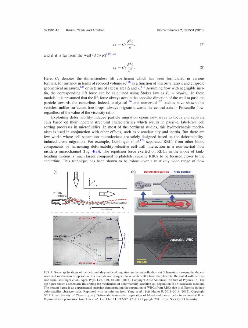
Exploiting deformability-induced particle migration opens new ways to focus and separate
cells based on their inherent structural characteristics which results in passive, label-free cell
sorting processes in microfluidics. In most of the pertinent studies, this hydrodynamic mecha-
nism is used in conjunction with other effects, such as viscoelasticity and inertia. But there are
few works where cell separation microdevices are solely designed based on the deformability-
induced cross migration. For example, Geislinger et al.128 separated RBCs from other blood
components by harnessing deformability-selective cell-wall interaction in a non-inertial flow
inside a microchannel (Fig. 4(a)). The repulsion force exerted on RBCs in the mode of tank-
treading motion is much larger compared to platelets, causing RBCs to be focused closer to the
centerline. This technique has been shown to be robust over a relatively wide range of flow
FIG. 4. Some applications of the deformability-induced migration in the microfluidics. (a) Schematics showing the dimen-
sions and mechanism of operation of a microdevice designed to separate RBCs from the platelets. Reprinted with permis-
sion from Geislinger et al., Appl. Phys. Lett. 100, 183701 (2012). Copyright 2012 American Institute of Physics. (b) The
top figure shows a schematic illustrating the mechanism of deformability-selective cell separation in a viscoelastic medium.
The bottom figure is an experimental snapshot demonstrating the separation of WBCs from RBCs due to difference in their
deformability characteristics. Reprinted with permission from Yang et al., Soft Matter 8, 5011–5019 (2012). Copyright
2012 Royal Society of Chemistry. (c) Deformability-selective separation of blood and cancer cells in an inertial flow.
Reprinted with permission from Hur et al., Lab Chip 11, 912–920 (2011). Copyright 2011 Royal Society of Chemistry.
021501-10 Karimi, Yazdi, and Ardekani Biomicrofluidics 7, 021501 (2013)

rates as far as the corresponding Reynolds number remains small. Working in the same inertia-
less regime, Yang et al.95 employed lateral lift forces arising from the combinational effects of
deformability and viscoelasticity to focus RBCs at the center of a microchannel in order to sep-
arate them from white blood cells (WBCs). As mentioned before, the particles flowing in a
viscoelastic medium inside a rectangular channel migrate toward the centerline as well as the
corners. Introducing deformability results in additional wall repulsion forces which selectively
entrains the particles at the corners. Considering the point that the deformability-induced lift
force depends on the asymmetry of the particle, it can be inferred that this force is negligible
for WBCs due to their near spherical shape. Hence, while RBCs mainly concentrate at the core
of the channel, WBCs can be selectively extracted along the corners. Using this setup, Yang
and coworkers95 could obtain WBCs with a purity of 35% from a dilute input solution with
WBC/RBC ratio of 0.17%. The design of their device and a snapshot of separated cells are
shown in Fig. 4(b). Although promising, this technique needs further development and improve-
ment to be comparable with commercial enrichment methods.
Incorporating the effect of inertia into the previous cell separation techniques can substan-
tially enhance the throughput. Utilizing this idea, Hur et al.66 designed a microfluidic device
for classification and enrichment of different types of cells based on their size and deformabil-
ity. Taking advantage of high aspect ratio channels leading to lower number of equilibrium
positions, they calibrated the device based on the unique lateral location of each category of
cells in order to detect and separate them using different outlets across the width of the channel.
By tuning Reynolds number to an optimum value, they achieved throughput of �22 000 cells/
min while yielding 96% recovery rate for the separation of metastatic breast cancer cells (see
Fig. 4(c)). This technique appears to be more effective for more deformable cells compared to
stiffer cells in terms of enrichment performance. Also, in this method the range of flow rates
should be carefully scrutinized in order not to alter the gene expression of the cells under the
effect of shear flow.
D. Dean flow
In inertial flows inside the channels with curved geometry, centrifugal forces create a sec-
ondary rotational flow, called Dean flow,129,130 which is of paramount importance in the flow
focusing applications in microfluidics. In curved rectangular channels, a parcel of fluid passing
through the central region of the channel is pushed outward due to centrifugal effects, and thus,
to satisfy the incompressibility condition, the fluid in the near-wall region is driven inwards.
Hence, two symmetric vortices on the top and bottom halves of the channel’s cross section are
established, leading to the formation of a pressure gradient in the radial direction. The strength
of this secondary flow can be quantified by the Dean number130
De ¼ Re
ffiffiffiffiffiffiffiffiDh
2Rc
r; (9)
where Rc denotes the radius of curvature of the channel. De can be physically interpreted as the
square root of the ratios of centrifugal and inertia forces to the viscous force. Its direct depend-
ence on the Reynolds number implies that the effect of Dean flow becomes significant in the in-
ertial regime where Re � Oð1Þ. The other important dimensionless parameter, where its value
largely influences the shape of the vortices, is the curvature ratio, d ¼ Dh=2Rc.130 Different
relationships between the velocity of Dean flow and the corresponding Dean number have been
put forward. For example, Ookawara et al.131 proposed the following correlation based on the
numerical simulations of the problem with a specific configuration
UD ¼ 1:8� 10�4 De1:63: (10)
But simple scaling arguments132 as well as experimental results of Gossett and Di Carlo133 sug-
gest that
021501-11 Karimi, Yazdi, and Ardekani Biomicrofluidics 7, 021501 (2013)

UD � De2l=qDh: (11)
This secondary flow exerts an additional drag force in the lateral direction on the particles mov-
ing along the channel axis. Using the latter expression for UD, the drag attributed to Dean flow
is found to scale as FD � qU2aD2h=Rc. This force always acts in a way that constraints the par-
ticles to follow the vortex path.
Inertial lift forces (FL) are also present in the cross-stream directions, and their balance
with Dean drag force determines the modified preferred locations of the particles. In fact, in
channels with curved geometry, the number of equilibrium positions are reduced compared to
straight channels because of destabilizing effect of the Dean force. Specifically, equilibrium
positions along the midline of the channel between two counter-rotating vortices will disappear,
leaving only two preferred locations for the particle focusing. This characteristic of the curved
channels makes them more suited for applications in ordering and separation.
To quantify the interplay between the lift and Dean drag forces, Di Carlo and co-
workers73,133 introduced an inertial force ratio, defined as
Rf �FL
FD¼ 2Rca2
D3h
; (12)
which characterizes different regimes of particulate flows in curved channels. It is noteworthy
that in the derivation of this ratio, the effects of some other components such as channel’s
Reynolds number and the lateral position of the particle for the sake of simplicity have been
ignored. It is argued133 that weak dependence of Rf on these factors does not alter its prowess
as a characterizing parameter of the system. Depending on the range of Rf, three regimes are
distinguishable: (a) if Rf � 1, the secondary flow becomes inconsequential compared to inertial
effects, (b) if Rf � 1, particles remain unfocused due to dominant strength of rotational flow,
and (c) if Rf � 1, an intermediate regime occurs where the number of inertial equilibrium posi-
tions are reduced due to Dean drag forces. Gossett and Di Carlo133 conducted numerous experi-
ments using 2.2 lm particles to obtain a phase diagram of the flow for different values of Rf,
and based on their conclusion, the intermediate range for their specific configuration starts at
Rf � 0:037. However, the universality of this result is questionable considering lack of general-
ity in the corresponding experiments in terms of variation in particle’s size and channel’s aspect
ratio.
Beside reducing the number of equilibrium positions, including curvature introduces
another important advantage over straight channels that can be crucial in terms of energy effi-
ciency. It is experimentally observed133 that when De is large enough, particles flowing in
curved microchannels reach their final stable positions while traveling shorter distances com-
pared to straight channels with an equivalent flow rate. Consequently, flow focusing applica-
tions using curving geometries encounter lower pressure drop due to the skin friction and thus
require less pumping power to drive the flow. Hence using this technique, higher throughputs
can be attained while maintaining the pressure lower than the leakage threshold.
Dean flow effects have been recently utilized in microfluidic devices for cell/particle sepa-
ration and focusing applications. In this regard, different curving profiles have been employed
such as single curves,134 spirals,67,135–139 and serpentine curves.61,63,133,140 Among these, spirals
are the most widely used geometry in microdevices as they yield a sufficiently large channel
length while occupying minimum surface area. The only disadvantage associated with spirals is
their intrinsic difficulty with parallelization to fulfill high-throughput systems. However, this
problem can be overcome to some extent by taking advantage of higher flow rates which are
essential to utilize the full capabilities of Dean flow effects.
Papautsky and coworkers67,135 were among the first research groups to employ spiral
microchannels for the purpose of passive focusing and separation. They experimentally and
numerically demonstrated135 that the secondary flow can be used to separate two different parti-
cle sizes flowing in an inertial regime inside a 5-loop spiral channel with two inlets and two
outlets. Based on their study, it was shown that large particles with blockage ratio of j > 0:07
021501-12 Karimi, Yazdi, and Ardekani Biomicrofluidics 7, 021501 (2013)

aggregate on the inner channel wall due to combined effects of lift and Dean drag forces, while
smaller particles are more dispersed in the outer regions of the channel. Later, they improved
their design67 in terms of throughput as well as the number of separated particle streams (see
Fig. 5(a)). Utilizing higher flow rates (De � 4� 20) and employing an additional wider straight
channel before the multiple outlets, they separated a mixture of three different particle sizes
with a separation efficiency of �90%. In both works, low aspect ratio channels were preferred
(H=W ¼ 0:5 in Ref. 135 and 0:18 < H=W < 0:28 in Ref. 67) to minimize the multiplicity of
equilibrium positions. Due to quadratic dependence of Rf on the particle diameter, larger par-
ticles are driven further towards the inner wall by the inertial forces, whereas in case of smaller
particles the dominant effect of Dean drag forces focus them closer to the centerline and the
outer wall. This passive mechanism provides a robust basis for multistream separation and
extraction of particles based on their size. The same setup has been also used67 for the sorting
of two types of neural cells, achieving separation efficiency of >80% with an incredible
throughput of �106 cells/min. The slight decrease of the separation efficiency can be attributed
FIG. 5. Some applications of Dean flow in microfluidic systems. (a) Schematic of a microdevice to separate different par-
ticles based on their size using combined inertial and secondary flow effects. In this spiral microchannel, larger particles
equilibrate along the inner wall, while smaller ones aggregate around the centerline. Reprinted with permission from
Kuntaegowdanahalli et al., Lab Chip 9, 2973–2980 (2009). Copyright 2009 Royal Society of Chemistry. (b) Experimental
pictures showing the cell ordering and encapsulation using a spiral microchannel. Reprinted with permission from Kemna
et al., Lab Chip 12, 2881–2887 (2012). Copyright 2012 Royal Society of Chemistry. (c) Schematic of a microfluidic system
to focus the particles using a curved microchannel as well as horizontal and vertical sheath flows. The lateral position of
the particles at different locations are depicted in panels 1-4. Reprinted with permission from Mao et al., Lab Chip 9,
1583–1589 (2009). Copyright 2009 Royal Society of Chemistry. (d) Fluorescent images of the particulate flow in a serpen-
tine microchannel show that by increasing flow rate and thus Dean number, particle focusing along a single stream is
achieved. Reprinted with permission from Oakey et al., Anal. Chem. 82, 3862–3867 (2010). Copyright 2010 American
Chemical Society.
021501-13 Karimi, Yazdi, and Ardekani Biomicrofluidics 7, 021501 (2013)

to the cell deformability effects which prevent the aggregation of the cells close to the walls.
The operational throughput of such systems working in the inertial regime is limited by two im-
portant factors: cell viability which might be damaged due to high shear rate effects, and clog-
ging problems which are likely to arise in microfluidic designs with multiple constrictions at
the outlet. Despite associated deficiencies, spirally shaped microchannels have been widely
used in various microfluidic applications, such as sheathless flow cytometry,136 cell cycle syn-
chronization and fractionation of asynchronous mammalian cell lines,141 delivery of exogenous
DNA payloads into cells,137 and single cell droplet encapsulation139 (Fig. 5(b)).
The vortical flow resulting from Dean effects have been also used to focus particles passing
though microchannels with a single curve.134 Adjusting the size of the particles and the channel
dimensions to maintain the value of Rf < 0:01 and employing two sets of sheath flows, Mao
et al.134 attained three-dimensional hydrodynamic focusing to ensure single cell passage through
the laser beam of flow cytometers. The mechanism of their device is schematically shown in
Fig. 5(c). In this drifting technique, 2D focusing is initially achieved because in the small Rf re-
gime inertial lift forces are negligible, leading to particles entrainment by Dean vortices and
their aggregation along the channel’s midline. In the next step, horizontal sheath flows, injected
normal to the axial direction, create 3D focusing along the centerline. Using the aforementioned
setup, a throughput of �105 particles/min for flow cytometry applications has been fulfilled.
However, further study is required to confirm the robustness of this method when dealing with
deformable cells instead of rigid particles.
Serpentine channels with variable radii of curvature and alternating curving directions pro-
vide high-throughput hydrodynamic focusing and separation techniques via parallelization on a
single substrate. The pioneering work of Di Carlo et al.63 illustrated the potential of this type
of geometry for cell/particle ordering purposes in the inertial flow. It is observed61,63 that in
asymmetric curving geometries, the destabilization of the equilibrium positions due to Dean
flow is amplified, leading to formation of a single stream of particles in shorter travelled distan-
ces compared to the straight or symmetrically curved channels (see Fig. 5(d)). As the threshold
pressure associated with the leakage is the main limiting design factor in such systems, the ser-
pentine geometry renders higher capacity to increase the throughput due to its inherently lower
pressure drop. Using this technique, Di Carlo et al.63 focused cells at a rate of �106 cells/min
with negligible damage to their viability. This method, although advantageous in terms of not
requiring additional sheath flows, is operationally limited to a specific range of flow rates for
optimum focusing performance. The corresponding interval of optimal channel Reynolds num-
ber can be approximately inferred from the phase diagram of particle ordering in curved micro-
channels133 in terms of associated value of Rf and the degree of focusing.
III. VORTICITY INDUCED TRAPPING
Vortex-induced trapping provides promising approaches for high-throughput size-selective
separation of cells and particles. These vortices can be generated using the geometrical modifi-
cation of the channel profile,72,142 by acoustic streaming143 or via electrokinetic methods, such
as induced-charge electro-osmosis,144 AC electro-osmosis,145 and dielectrophoresis.146,147 The
optimum conditions for particle trapping in confined microvortex flows have been analyzed ana-
lytically and numerically by Liu et al.148 using the concepts of nonlinear dynamics. It has been
shown that introducing non-hydrodynamic forces can substantially improve the efficiency of
vortical, point, and ring traps. In this section, a brief review of studies regarding the production
of vortices by means of streaming bubbles or solid boundaries is presented.
A. Cavitation microstreaming
Oscillating bubbles have shown a great deal of promise in fluid and particle/cell manipula-
tion in microfluidic systems. They are greatly beneficial in a number of proposed applications
in chemical, biological, and physical processes such as mixing,149–151 pumping,152,153 character-
izing enzymatic reactions,154 cell lysis,155 and sorting and enrichment.156,157 A thorough review
article on applications of oscillating microbubbles in microfluidics is recently written by
021501-14 Karimi, Yazdi, and Ardekani Biomicrofluidics 7, 021501 (2013)

Hashmi et al.158 Although, there are a number of techniques to generate bubbles in microfluidic
channels,159,160 using a cavity is found to be the simplest. Upon generation of the bubble, a pie-
zoelectric transducer can be coupled with the device to oscillate the bubble. Despite being sim-
ple, this manner of inducing bubble oscillation is rather accurate and efficient. Upon oscillation,
a bubble can vibrate under linear or non-linear response depending upon the amplitude of the
vibration.161 The fast vibration of the bubble’s interface produces a second order streaming flow
that has a steady component. However, time-averaging leaves only the steady part since sam-
pling rate is at rates much slower than oscillation frequency. The steady flow, known as
“cavitation microstreaming,”162,163 has streaming Reynolds number defined as Res 2p�2a2f=�,
where �; a; �a, and f are the kinematic viscosity of the liquid, bubble radius, oscillation ampli-
tude, and frequency, respectively. Depending on f, bubble oscillates in different oscillation
modes; however, oscillation amplitude and the corresponding cavitation microstreaming are
more pronounced when the bubble is excited at its resonance frequency.158,164 For Res � 1, flow
is described as Rayleigh-Nyborg-Westervelt (RNW) streaming and can be modeled using the
method of images and singularity.165 The maximum streaming velocity, which is located near
the bubble, can then be approximated from us � 2p�2af .155 However, in high applied voltages
and typical applied frequencies in microfluidic systems156,157 (15 kHz < f < 100 kHz), Res � 1
which makes the theoretical solution more complicated as the full Navier-Stokes equations must
be solved. Nevertheless, RNW streaming can describe the flow in these cases quite accurately.157
Within a typical microfluidic experimental setup149,156 the streaming velocity is on the order of
mm/s to cm/s, which makes the manipulation of the liquid and particles in microchannels using
oscillating bubbles a powerful yet efficient and simple technique compared to electrokinetics and
electrophoresis.144,166–168
Recently, Wang et al.156,157 used the cavitation microstreaming of a bubble together with
Poiseuille flow to manipulate particles and their spatial concentration for enrichment, filtering
and focusing applications in microfluidic devices. The working mechanism is based on the fact
that particles behave differently around the oscillating bubbles depending on their finite-size.
When the relative streaming strength ratio, defined as s �up=us, where �up is the mean
Poiseuille velocity, is low, the streaming flow dominates near the bubble with two vortices.
Under this condition, near the oscillating bubble, particles larger than a critical size (ap > dgap,
where ap is the particle radius and dgap is a characteristic size of the gap, dictating the critical
size) are forced to move across the streamlines towards the vortex of microstreaming and even-
tually be trapped in the streaming. This is due to the fact that the particles cannot penetrate the
bubble, so they move across streamlines because of finite size effects. The gap width dgap,
which is the distance between the surface of the bubble and closed streamlines in the vortex,
can be theoretically predicted using a geometry argument156 as dgap ¼ sh½3ðh=HÞ � 2ðh=HÞ2.Here, H is the width of the channel and h is the portion of the channel width in which the
streamlines are rectified to pass through dgap when the streaming is present near the bubble.
The equation for obtaining dgap is derived using the conservation of mass which dictates that
the mass flux in portion h of the channel must pass through the gap between the closed stream-
lines and the bubble. This mechanism, described schematically in Fig. 6, can lead to high
FIG. 6. Mechanism of trapping: (a) streak image highlighting the hyperbolic point P and critical streamline and (b) sche-
matic detail of the boxed region of panel (a). Reprinted with permission from Wang et al., Appl. Phys. Lett. 99, 034101
(2011). Copyright 2011 American Institute of Physics.
021501-15 Karimi, Yazdi, and Ardekani Biomicrofluidics 7, 021501 (2013)

concentration of the target particles in vicinity of the bubbles which can be used for particle
enrichment (Fig. 7). However, as the number of trapped particles increases, particle-particle
interactions eventually lead to the release of particles from the vortex. These interactions, such
as collisions and hydrodynamic interactions, cause perturbations in the particle trajectories
which allow particles to enter the region of open streamlines. The release of the particles occurs
at a narrow region near the bubble pole where the perturbations are stronger. Wang et al.157
used the releasing technique for focusing applications since the release trajectory is narrower
than the trajectories far upstream of the bubble.157 Depending on dgap, more than one size of
particles can be trapped within the vortical flow. As these particles are transported in the
streaming flow, they gradually settle into different closed trajectories depending on their size as
illustrated in Fig. 8. The small particle orbits on a larger loop while the large particle orbits on
a smaller trajectory.
The same cavitation microstreaming approach based on finite size effects can be used to
collect motile bacterial cells in the vortical flow of an oscillating bubble as shown by Yazdi
and Ardekani.169 In this case, they observed rapid formation of biofilm streamers which occurs
due to the presence of the microstreaming vortices. They also showed that bacterial motility
affects the rate of collection of bacteria in the vortices suggesting that bacteria with high motil-
ity are trapped faster and more intense in the vortical flow. Fig. 9 shows the collection of bacte-
ria in the microstreaming of an oscillating bubble and the biofilm streamer formed after three
minutes.
FIG. 7. Accumulation of microparticles around an oscillating bubble. Snapshots (b) and (c) are taken 2 s and 4 s after (a),
respectively. Reprinted with permission from Wang et al., Biomicrofluidics 6, 012801 (2012). Copyright 2012 American
Institute of Physics.
FIG. 8. Schematic illustration of characteristic loops of large and small particles. Reprinted with permission from Wang
et al., Biomicrofluidics 6, 012801 (2012). Copyright 2012 American Institute of Physics.
021501-16 Karimi, Yazdi, and Ardekani Biomicrofluidics 7, 021501 (2013)

B. Hydrodynamic tweezers
An alternative way of trapping cells by acoustic streaming is by utilizing an oscillating
solid boundary in a microfluidic system. The solid boundary can be a fixed cylinder in the mid-
dle of the channel (see Fig. 10(a)) or a sharp edge of a cavity in the channel wall. By applying
low audible frequencies (250 Hz � f � 1000 Hz), time-averaged secondary streaming, known
as “steady streaming,” similar to cavitation microstreaming, is generated adjacent to the solid
boundary. These streamings are driven by Reynolds stresses that are created within the Stokes
layer near solid boundaries. Representative streamlines of the streaming flow at different planes
of symmetry have been shown in Figs. 10(b) and 10(c). Stokes layer thickness, dAC ¼ ð�=f Þ1=2,
is a scaling parameter for oscillating flows that describes how far from a surface the viscous
damping of an oscillating boundary persists.170 Here, � and f are fluid kinematic viscosity and
cylinder’s oscillation frequency, respectively.
Lutz et al.171 used this technique for dynamic single-cell measurements. The secondary
flow in the vicinity of a fixed oscillating cylindrical obstacle in a microfluidic channel, with ra-
dius of 125 lm, was used to trap and suspend single-cells, including motile cells. Upon apply-
ing the audible-frequency fluid oscillation, the trapping force draws the cell toward the cylinder.
The magnitude of the trapping force, which is directly related to the amplitude of oscillation, is
up to 30 pN, and it is of the same order of magnitude as forces induced by optical tweezers
and dielectrophoretic traps. However, unlike these techniques, the magnitude of shear stress
generated by the oscillating fluid is �1:5 N=m2, which is within the physiological range for
cells and arterial blood flow. Location of the trapping is near the eddy center, and it is con-
trolled via the oscillation frequency. They have further shown that by adjusting the applied fre-
quency, device geometry, and fluid kinematic viscosity, the depth of the trapping eddy can be
matched to the diameter of the cell. Therefore, despite the different initial positions of the cells,
they are ultimately positioned at a specific location within the channel’s midplane. It should be
FIG. 9. Bacterial collection in a vortical flow of an oscillating bubble trapped in a horse-shoe structure for (a) low motile
bacteria (E. coli DH5a) and (b) high motile (E. coli RP437). (c) Rapid biofilm formation in the vicinity of the bubble.
Reprinted with permission from S. H. Yazdi and A. M. Ardekani, Biomicrofluidics 6, 044114 (2012). Copyright 2012
American Institute of Physics.
FIG. 10. (a) Schematic representation of the flow channel and the symmetry planes as observed in experiments. (b) The
image of particle pathlines at plane A for particle size ap ¼ 500 lm. (c) Schematic streamlines of streaming flow at planes
B and C. Reprinted with permission from Lutz et al., Fluids 17, 023601 (2005). Copyright 2012 American Institute of
Physics.
021501-17 Karimi, Yazdi, and Ardekani Biomicrofluidics 7, 021501 (2013)

noted that due to the low range of applied frequency and intensity, the acoustical effects associ-
ated with radiation force and bulk energy absorption are not important here. Recently, they
expanded their design to cavities as well as other obstacles in a microfluidic channel and inves-
tigated the effect of design geometry on steady streaming flow shape, structure, and strength by
conducting the experiments in channels with different oscillating boundaries.172 In this work,
they improved upon their previous observation and showed that the trapping location is closer
to the solid boundary than the core of the eddy. The overall reported results of the particle trap-
ping are quite similar among different posts; however, steady flow structure, strength, and trap-
ping stability in cavities are significantly different.172
IV. PERSPECTIVES
Employing hydrodynamic effects in microfluidic applications has been distinguished in the
past decade to be fruitful both in terms of throughput and efficiency and continues to thrive in
the future through further improvements in separation resolution and processing rate. However,
there are new areas for applications of hydrodynamic microfluidic phenomena which appear
promising and demand further investigations, both theoretically to inform researchers of the
underlying physics and experimentally to exploit them in biological applications. Although sev-
eral active separation techniques have been developed to meet the growing demand in these
new territories, they lack the associated advantages of the passive methods reviewed in previous
sections, such as ease of design and maintaining the viability of genes. Sorting micro/nano-scale
chiral objects by means of lateral drift induced by shear flow is among those areas requiring
further studies. Chirality is a common property of many biomolecules, including well-
celebrated DNA strands.173 Separating these molecules based on their chirality is strongly use-
ful in a variety of applications ranging from food industries to pharmaceutical products.
Considering the inherent difficulties of the currently available methods, several attempts have
been made to harness chirality-induced lift forces arising in a shear flow to separate the
molecules.174–176 Recently, Marcos et al.176 presented a technique to fulfill this purpose, achiev-
ing an ample efficiency (>80%) for the separation of microscale, dormant helical bacteria.
Nevertheless, further work is required to expand the scope of this method in terms of operating
at higher throughput and separating smaller chiral objects at nanoscale. Proceeding in this con-
text, cross-stream migration in a viscoelastic medium has been utilized to focus two types of
double-helical DNA molecules (radii of gyration �Oð0:1� 1Þlm) in the vicinity of the center-
line of a microchannel.98 However, the throughput of this technique is limited due to its opera-
tional flow rate corresponding to Re � Oð10�3Þ. By decreasing the size of the molecules,
Brownian diffusive effects become significant which tend to destroy the focusing and alignment
of separated objects. It will be interesting to seek new methods to remedy this problem and
broaden the application of microfluidic techniques.
Even though trapping and ordering processes are well studied for non-motile cells, the
interplay of cell motility with other hydrodynamic effects influencing the lateral migration is
mostly overlooked. However in recent years, few studies have been conducted to shed light on
the interaction between swimming behavior and shear flow. For example, Durham et al.177
experimentally demonstrated the generation of intense accumulations of phytoplankton in the
high-shear regions of confined flows due to tumbling behavior of the cells triggered by exces-
sive hydrodynamic torque. In the microfluidic framework, Hashemi et al.178 designed and fabri-
cated a flow cytometer comprised of two sheath flows and a central sample stream in order to
hydrodynamically focus and characterize various phytoplankton species. Also, Ardekani and
Gore179 have analytically shown that cross-stream migration induced by viscoelasticity can be
used to aggregate bacterial cells in a vortical flow in order to generate large enough concentra-
tions of microorganisms required for detection procedures. From practical point of view, detec-
tion of microorganisms such as bacteria is important in medical diagnosis and microbiological
analysis of food, water, and environmental samples. Thus, another prominent area for future
research can be towards providing insight upon the basic physics of lateral migration of motile
cells in confined flows and its application in environmental and biological studies.
021501-18 Karimi, Yazdi, and Ardekani Biomicrofluidics 7, 021501 (2013)

ACKNOWLEDGMENTS
The research was supported by NSF (Grant No. CBET-1150348-CAREER) and by Lilly
Endowment, Inc. (Grant No. 2004 1572-000).
1M. Danova, M. Torchio, and G. Mazzini, “Isolation of rare circulating tumor cells in cancer patients: Technical aspectsand clinical implications,” Expert Rev. Mol. Diagn. 11, 473–485 (2011).
2D. C. Colter, I. Sekiya, and D. J. Prockop, “Identification of a subpopulation of rapidly self-renewing and multipotentialadult stem cells in colonies of human marrow stromal cells,” Proc. Natl. Acad. Sci. 98, 7841–7845 (2001).
3K. Jo, Y.-L. Chen, J. J. de Pablo, and D. C. Schwartz, “Elongation and migration of single DNA molecules in micro-channels using oscillatory shear flows,” Lab Chip 9, 2348–2355 (2009).
4P. Gascoyne, J. Satayavivad, and M. Ruchirawat, “Microfluidic approaches to malaria detection,” Acta Tropica 89,357–369 (2004).
5A. van de Stolpe, K. Pantel, S. Sleijfer, L. W. Terstappen, and J. M. J. den Toonder, “Circulating tumor cell isolationand diagnostics: Toward routine clinical use,” Cancer Res. 71, 5955–5960 (2011).
6X. Cheng, D. Irimia, M. Dixon, K. Sekine, U. Demirci, L. Zamir, R. G. Tompkins, W. Rodriguez, and M. Toner, “A micro-fluidic device for practical label-free CD4þ T cell counting of HIV-infected subjects,” Lab Chip 7, 170–178 (2007).
7J. den Toonder, “Circulating tumor cells: The grand challenge,” Lab Chip 11, 375–377 (2011).8D. G€anshirt, F. W. M. Smeets, A. Dohr, C. Walde, I. Steen, C. Lapucci, C. Falcinelli, R. Sant, M. Velasco, and H. S. P.Garritsen, “Enrichment of fetal nucleated red blood cells from the maternal circulation for prenatal diagnosis:Experiences with triple density gradient and MACS based on more than 600 cases,” Fetal Diagn. Ther. 13, 276–286(1998).
9G. Vona, A. Sabile, M. Louha, V. Sitruk, S. Romana, K. Sch€utze, F. Capron, D. Franco, M. Pazzagli, M. Vekemanset al., “Isolation by size of epithelial tumor cells: A new method for the immunomorphological and molecular characteri-zation of circulating tumor cells,” Am. J. Pathol. 156, 57–63 (2000).
10C. Alix-Panabieres, J. Vendrell, O. Pell�e, X. Rebillard, S. Riethdorf, V. M€uller, M. Fabbro, and K. Pantel, “Detectionand characterization of putative metastatic precursor cells in cancer patients,” Clin. Chem. 53, 537–539 (2007).
11H. M. Shapiro, Practical Flow Cytometry, 4th ed. (Wiley-Liss, New York, 2003).12S. Miltenyi, W. M€uller, W. Weichel, and A. Radbruch, “High gradient magnetic cell separation with MACS,”
Cytometry 11, 231–238 (1990).13A. A. S. Bhagat, H. Bow, H. W. Hou, S. J. Tan, J. Han, and C. T. Lim, “Microfluidics for cell separation,” Med. Biol.
Eng. Comput. 48, 999–1014 (2010).14A. H. J. Yang, S. D. Moore, B. S. Schmidt, M. Klug, M. Lipson, and D. Erickson, “Optical manipulation of nanoparticles
and biomolecules in sub-wavelength slot waveguides,” Nature (London) 457, 71–75 (2009).15A. E. Cohen, “Control of nanoparticles with arbitrary two-dimensional force fields,” Phys. Rev. Lett. 94, 118102 (2005).16H. Lee, A. M. Purdon, and R. M. Westervelt, “Manipulation of biological cells using a microelectromagnet matrix,”
Appl. Phys. Lett. 85, 1063–1065 (2004).17M. Evander, L. Johansson, T. Lilliehorn, J. Piskur, M. Lindvall, S. Johansson, M. Almqvist, T. Laurell, and J. Nilsson,
“Noninvasive acoustic cell trapping in a microfluidic perfusion system for online bioassays,” Anal. Chem. 79,2984–2991 (2007).
18R. Dylla-Spears, J. E. Townsend, L. Jen-Jacobson, L. L. Sohn, and S. J. Muller, “Single-molecule sequence detectionvia microfluidic planar extensional flow at a stagnation point,” Lab Chip 10, 1543–1549 (2010).
19R. Pethig, “Review article—dielectrophoresis: Status of the theory, technology, and applications,” Biomicrofluidics 4,022811 (2010).
20S. Patel, D. Showers, P. Vedantam, T. R. Tzeng, S. Qian, and X. Xuan, “Microfluidic separation of live and dead yeastcells using reservoir-based dielectrophoresis,” Biomicrofluidics 6, 034102 (2012).
21Z. Gagnon, J. Mazur, and H. C. Chang, “Glutaraldehyde enhanced dielectrophoretic yeast cell separation,”Biomicrofluidics 3, 044108 (2009).
22M. Muratore, V. Srsen, M. Waterfall, A. Downes, and R. Pethig, “Biomarker-free dielectrophoretic sorting of differenti-ating myoblast multipotent progenitor cells and their membrane analysis by Raman spectroscopy,” Biomicrofluidics 6,034113 (2012).
23S. N. Murthy, “Magnetophoresis: An approach to enhance transdermal drug diffusion,” Die Pharmazie 54, 377 (1999).24J. S. Heyman, “Acoustophoresis separation method,” U.S. patent 5,192,450 (1993).25M. P. MacDonald, G. C. Spalding, and K. Dholakia, “Microfluidic sorting in an optical lattice,” Nature (London) 426,
421–424 (2003).26M. Yamada, M. Nakashima, and M. Seki, “Pinched flow fractionation: Continuous size separation of particles utilizing a
laminar flow profile in a pinched microchannel,” Anal. Chem. 76, 5465–5471 (2004).27T. A. Crowley and V. Pizziconi, “Isolation of plasma from whole blood using planar microfilters for lab-on-a-chip
applications,” Lab Chip 5, 922–929 (2005).28S. Yang, A. €Undar, and J. D. Zahn, “A microfluidic device for continuous, real time blood plasma separation,” Lab Chip
6, 871–880 (2006).29S. Choi, S. Song, C. Choi, and J. K. Park, “Continuous blood cell separation by hydrophoretic filtration,” Lab Chip 7,
1532–1538 (2007).30J. A. Davis, D. W. Inglis, K. J. Morton, D. A. Lawrence, L. R. Huang, S. Y. Chou, J. C. Sturm, and R. H. Austin,
“Deterministic hydrodynamics: Taking blood apart,” Proc. Natl. Acad. Sci. 103, 14779–14784 (2006).31J. Friend and L. Yeo, “Microscale acoustofluidics: Microfluidics driven via acoustics and ultrasonics,” Rev. Mod. Phys.
83, 647 (2011).32A. Lenshof and T. Laurell, “Continuous separation of cells and particles in microfluidic systems,” Chem. Soc. Rev. 39,
1203–1217 (2010).33X. Xuan, J. Zhu, and C. Church, “Particle focusing in microfluidic devices,” Microfluid. Nanofluid. 9, 1–16 (2010).
021501-19 Karimi, Yazdi, and Ardekani Biomicrofluidics 7, 021501 (2013)

34D. R. Gossett, W. M. Weaver, A. J. Mach, S. C. Hur, H. T. K. Tse, W. Lee, H. Amini, and D. Di Carlo, “Label-free cellseparation and sorting in microfluidic systems,” Anal. Bioanal. Chem. 397, 3249–3267 (2010).
35J. Chen, J. Li, and Y. Sun, “Microfluidic approaches for cancer cell detection, characterization, and separation,” LabChip 12, 1753–1767 (2012).
36J. Autebert, B. Coudert, F. C. Bidard, J. Y. Pierga, S. Descroix, L. Malaquin, and J. L. Viovy, “Microfluidic: An innova-tive tool for efficient cell sorting,” Methods 57, 297–307 (2012).
37H. Chang and G. Yossifon, “Understanding electrokinetics at the nanoscale: A perspective,” Biomicrofluidics 3, 012001(2009).
38L. Y. Yeo and J. R. Friend, “Ultrafast microfluidics using surface acoustic waves,” Biomicrofluidics 3, 012002 (2009).39J. Nilsson, M. Evander, B. Hammarstrom, and T. Laurell, “Review of cell and particle trapping in microfluidic systems,”
Anal. Chim. Acta 649, 141–157 (2009).40L. G. Leal, “Particle motions in a viscous fluid,” Annu. Rev. Fluid Mech. 12, 435–476 (1980).41L. G. Leal, Advanced Transport Phenomena: Fluid Mechanics and Convective Transport Processes (Cambridge
University Press, Cambridge, 2007).42G. Segre, “Radial particle displacements in Poiseuille flow of suspensions,” Nature (London) 189, 209–210 (1961).43G. Segre and A. Silberberg, “Behaviour of macroscopic rigid spheres in Poiseuille flow. Part 1. Determination of local
concentration by statistical analysis of particle passages through crossed light beams,” J. Fluid Mech. 14, 115–135(1962).
44G. Segre and A. Silberberg, “Behaviour of macroscopic rigid spheres in Poiseuille flow. Part 2. Experimental results andinterpretation,” J. Fluid Mech. 14, 136–157 (1962).
45J. P. Matas, J. F. Morris, and E. Guazzelli, “Lateral forces on a sphere,” Oil Gas Sci. Technol. 59, 59–70 (2004).46B. P. Ho and L. G. Leal, “Inertial migration of rigid spheres in two-dimensional unidirectional flows,” J. Fluid Mech. 65,
365–400 (1974).47R. G. Cox and S. K. Hsu, “The lateral migration of solid particles in a laminar flow near a plane,” Int. J. Multiphase
Flow 3, 201–222 (1977).48J. A. Schonberg and E. J. Hinch, “Inertial migration of a sphere in Poiseuille flow,” J. Fluid Mech. 203, 517–524
(1989).49A. J. Hogg, “The inertial migration of non-neutrally buoyant spherical particles in two-dimensional shear flows,”
J. Fluid Mech. 272, 285–318 (1994).50E. S. Asmolov, “The inertial lift on a spherical particle in a plane Poiseuille flow at large channel Reynolds number,”
J. Fluid Mech. 381, 63–87 (1999).51E. S. Asmolov, “The inertial lift on a small particle in a weak-shear parabolic flow,” Phys. Fluids 14, 15 (2002).52J. S. Halow and G. B. Wills, “Radial migration of spherical particles in Couette systems,” AIChE J. 16, 281–286 (1970).53J. P. Matas, J. F. Morris, and E. Guazzelli, “Inertial migration of rigid spherical particles in Poiseuille flow,” J. Fluid
Mech. 515, 171–195 (2004).54Y. S. Choi, K. W. Seo, and S. J. Lee, “Lateral and cross-lateral focusing of spherical particles in a square microchannel,”
Lab Chip 11, 460–465 (2011).55J. Feng, H. H. Hu, and D. D. Joseph, “Direct simulation of initial value problems for the motion of solid bodies in a
Newtonian fluid. Part 2. Couette and Poiseuille flows,” J. Fluid Mech. 277, 271–301 (1994).56L. Zeng, S. Balachandar, and P. Fischer, “Wall-induced forces on a rigid sphere at finite Reynolds number,” J. Fluid
Mech. 536, 1–25 (2005).57B. Chun and A. J. C. Ladd, “Inertial migration of neutrally buoyant particles in a square duct: An investigation of multi-
ple equilibrium positions,” Phys. Fluids 18, 031704 (2006).58D. Di Carlo, J. F. Edd, K. J. Humphry, H. A. Stone, and M. Toner, “Particle segregation and dynamics in confined
flows,” Phys. Rev. Lett. 102, 94503 (2009).59D. R. Gossett, H. T. K. Tse, J. S. Dudani, K. Goda, T. A. Woods, S. W. Graves, and D. Di Carlo, “Inertial manipulation
and transfer of microparticles across laminar fluid streams,” Small 8, 2757–2764 (2012).60A. A. S. Bhagat, H. W. Hou, L. D. Li, C. T. Lim, and J. Han, “Pinched flow coupled shear-modulated inertial microflui-
dics for high-throughput rare blood cell separation,” Lab Chip 11, 1870–1878 (2011).61J. Oakey, R. W. Applegate, Jr., E. Arellano, D. D. Carlo, S. W. Graves, and M. Toner, “Particle focusing in staged iner-
tial microfluidic devices for flow cytometry,” Anal. Chem. 82, 3862–3867 (2010).62X. Mao, J. R. Waldeisen, and T. J. Huang, “‘Microfluidic drifting’–Implementing three-dimensional hydrodynamic fo-
cusing with a single-layer planar microfluidic device,” Lab Chip 7, 1260–1262 (2007).63D. Di Carlo, D. Irimia, R. G. Tompkins, and M. Toner, “Continuous inertial focusing, ordering, and separation of par-
ticles in microchannels,” Proc. Natl. Acad. Sci. 104, 18892–18897 (2007).64S. C. Hur, H. T. K. Tse, and D. Di Carlo, “Sheathless inertial cell ordering for extreme throughput flow cytometry,” Lab
Chip 10, 274–280 (2010).65Z. Wu, B. Willing, J. Bjerketorp, J. K. Jansson, and K. Hjort, “Soft inertial microfluidics for high throughput separation
of bacteria from human blood cells,” Lab Chip 9, 1193–1199 (2009).66S. C. Hur, N. K. Henderson-MacLennan, E. R. B. McCabe, and D. Di Carlo, “Deformability-based cell classification
and enrichment using inertial microfluidics,” Lab Chip 11, 912–920 (2011).67S. S. Kuntaegowdanahalli, A. A. S. Bhagat, G. Kumar, and I. Papautsky, “Inertial microfluidics for continuous particle
separation in spiral microchannels,” Lab Chip 9, 2973–2980 (2009).68W. Lee, H. Amini, H. A. Stone, and D. Di Carlo, “Dynamic self-assembly and control of microfluidic particle crystals,”
Proc. Natl. Acad. Sci. 107, 22413–22418 (2010).69A. J. Mach and D. Di Carlo, “Continuous scalable blood filtration device using inertial microfluidics,” Biotechnol.
Bioeng. 107, 302–311 (2010).70D. Di Carlo, F. Jon, D. Irimia, R. G. Tompkins, and M. Toner, “Equilibrium separation and filtration of particles using
differential inertial focusing,” Anal. Chem. 80, 2204–2211 (2008).71A. A. S. Bhagat, S. S. Kuntaegowdanahalli, and I. Papautsky, “Inertial microfluidics for continuous particle filtration
and extraction,” Microfluid. Nanofluid. 7, 217–226 (2009).
021501-20 Karimi, Yazdi, and Ardekani Biomicrofluidics 7, 021501 (2013)

72S. C. Hur, A. J. Mach, and D. Di Carlo, “High-throughput size-based rare cell enrichment using microscale vortices,”Biomicrofluidics 5, 022206 (2011).
73D. Di Carlo, “Inertial microfluidics,” Lab Chip 9, 3038–3046 (2009).74J. Takagi, M. Yamada, M. Yasuda, and M. Seki, “Continuous particle separation in a microchannel having asymmetri-
cally arranged multiple branches,” Lab Chip 5, 778–784 (2005).75M. Yamada and M. Seki, “Hydrodynamic filtration for on-chip particle concentration and classification utilizing micro-
fluidics,” Lab Chip 5, 1233–1239 (2005).76L. R. Huang, E. C. Cox, R. H. Austin, and J. C. Sturm, “Continuous particle separation through deterministic lateral dis-
placement,” Science 304, 987–990 (2004).77D. W. Inglis, J. A. Davis, R. H. Austin, and J. C. Sturm, “Critical particle size for fractionation by deterministic lateral
displacement,” Lab Chip 6, 655–658 (2006).78B. R. Long, M. Heller, J. P. Beech, H. Linke, H. Bruus, and J. O. Tegenfeldt, “Multidirectional sorting modes in deter-
ministic lateral displacement devices,” Phys. Rev. E 78, 046304 (2008).79S. Choi and J. K. Park, “Continuous hydrophoretic separation and sizing of microparticles using slanted obstacles in a
microchannel,” Lab Chip 7, 890–897 (2007).80S. Choi, S. Song, C. Choi, and J. K. Park, “Microfluidic self-sorting of mammalian cells to achieve cell cycle synchrony
by hydrophoresis,” Anal. Chem. 81, 1964–1968 (2009).81J. S. Park, S. H. Song, and H. I. Jung, “Continuous focusing of microparticles using inertial lift force and vorticity via
multi-orifice microfluidic channels,” Lab Chip 9, 939–948 (2009).82J. S. Park and H. I. Jung, “Multiorifice flow fractionation: Continuous size-based separation of microspheres using a se-
ries of contraction/expansion microchannels,” Anal. Chem. 81, 8280–8288 (2009).83A. Karnis and S. G. Mason, “Particle motions in sheared suspensions. XIX. Viscoelastic media,” Trans. Soc. Rheol. 10,
571–592 (1966).84F. Gauthier, H. L. Goldsmith, and S. G. Mason, “Particle motions in non-Newtonian media. II. Poiseuille flow,” Trans.
Soc. Rheol. 15, 297–330 (1971).85E. Bartram, H. L. Goldsmith, and S. G. Mason, “Particle motions in non-Newtonian media,” Rheol. Acta 14, 776–782
(1975).86M. A. Tehrani, “An experimental study of particle migration in pipe flow of viscoelastic fluids,” J. Rheol. 40,
1057–1077 (1996).87B. P. Ho and L. G. Leal, “Migration of rigid spheres in a two-dimensional unidirectional shear flow of a second-order
fluid,” J. Fluid Mech. 76, 783 (1976).88P. Y. Huang, J. Feng, H. H. Hu, and D. D. Joseph, “Direct simulation of the motion of solid particles in Couette and
Poiseuille flows of viscoelastic fluids,” J. Fluid Mech. 343, 73–94 (1997).89A. M. Ardekani, R. H. Rangel, and D. D. Joseph, “Motion of a sphere normal to a wall in a second-order fluid,” J. Fluid
Mech. 587, 163–172 (2007).90A. M. Ardekani, R. H. Rangel, and D. D. Joseph, “Two spheres in a free stream of a second-order fluid,” Phys. Fluids
20, 063101 (2008).91S. A. Dhahir and K. Walters, “On non-Newtonian flow past a cylinder in a confined flow,” J. Rheol. 33, 781–804 (1989).92P. Y. Huang and D. D. Joseph, “Effects of shear thinning on migration of neutrally buoyant particles in pressure driven
flow of Newtonian and viscoelastic fluids,” J. Non-Newtonian Fluid Mech. 90, 159–185 (2000).93R. B. Bird, R. C. Armstrong, and O. Hassager, Dynamics of Polymeric Liquids: Fluid Mechanics (John Wiley and Sons,
Inc., New York, NY, 1987), Vol. 1.94A. M. Leshansky, A. Bransky, N. Korin, and U. Dinnar, “Tunable nonlinear viscoelastic “focusing” in a microfluidic
device,” Phys. Rev. Lett. 98, 234501 (2007).95S. Yang, S. S. Lee, S. W. Ahn, K. Kang, W. Shim, G. Lee, K. Hyun, and J. M. Kim, “Deformability-selective particle
entrainment and separation in a rectangular microchannel using medium viscoelasticity,” Soft Matter 8, 5011–5019(2012).
96G. D’Avino, P. L. Maffettone, F. Greco, and M. A. Hulsen, “Viscoelasticity-induced migration of a rigid sphere in con-fined shear flow,” J. Non-Newtonian Fluid Mech. 165, 466–474 (2010).
97G. D’Avino, G. Romeo, M. M. Villone, F. Greco, P. A. Netti, and P. L. Maffettone, “Single line particle focusinginduced by viscoelasticity of the suspending liquid: Theory, experiments and simulations to design a micropipe flow-focuser,” Lab Chip 12, 1638–1645 (2012).
98J. Y. Kim, S. W. Ahn, S. S. Lee, and J. M. Kim, “Lateral migration and focusing of colloidal particles and DNA mole-cules under viscoelastic flow,” Lab Chip 12, 2807–2814 (2012).
99S. Yang, J. Y. Kim, S. J. Lee, S. S. Lee, and J. M. Kim, “Sheathless elasto-inertial particle focusing and continuous sepa-ration in a straight rectangular microchannel,” Lab Chip 11, 266–273 (2011).
100J. Nam, H. Lim, D. Kim, H. Jung, and S. Shin, “Continuous separation of microparticles in a microfluidic channel viathe elasto-inertial effect of non-Newtonian fluid,” Lab Chip 12, 1347–1354 (2012).
101A. M. Dondorp, P. A. Kager, J. Vreeken, and N. J. White, “Abnormal blood flow and red blood cell deformability insevere malaria,” Parasitol. Today 16, 228–232 (2000).
102F. C. Mokken, M. Kedaria, C. P. Henny, M. R. Hardeman, and A. W. Gelb, “The clinical importance of erythrocytedeformability, a hemorrheological parameter,” Ann. Hematol. 64, 113–122 (1992).
103S. E. Cross, Y. S. Jin, J. Rao, and J. K. Gimzewski, “Nanomechanical analysis of cells from cancer patients,” Nat.Nanotechnol. 2, 780–783 (2007).
104S. Suresh, “Biomechanics and biophysics of cancer cells,” Acta Mater. 55, 3989–4014 (2007).105S. K. Ballas, “Sickle cell anemia with few painful crises is characterized by decreased red cell deformability and
increased number of dense cells,” Am. J. Hematol. 36, 122–130 (2006).106P. C. H. Chan and L. G. Leal, “The motion of a deformable drop in a second-order fluid,” J. Fluid Mech. 92, 131–170
(1979).107F. Takemura, S. Takagi, J. Magnaudet, and Y. Matsumoto, “Drag and lift forces on a bubble rising near a vertical wall
in a viscous liquid,” J. Fluid Mech. 461, 277–300 (2002).
021501-21 Karimi, Yazdi, and Ardekani Biomicrofluidics 7, 021501 (2013)

108F. Takemura and J. Magnaudet, “The transverse force on clean and contaminated bubbles rising near a vertical wall atmoderate Reynolds number,” J. Fluid Mech. 495, 235–253 (2003).
109J. Magnaudet, S. Takagi, and D. Legendre, “Drag, deformation and lateral migration of a buoyant drop moving near awall,” J. Fluid Mech. 476, 115–157 (2003).
110S. K. Doddi and P. Bagchi, “Lateral migration of a capsule in a plane Poiseuille flow in a channel,” Int. J. MultiphaseFlow 34, 966–986 (2008).
111S. Mortazavi and G. Tryggvason, “A numerical study of the motion of drops in Poiseuille flow. Part 1. Lateral migrationof one drop,” J. Fluid Mech. 411, 325–350 (2000).
112B. Lorz, R. Simson, J. Nardi, and E. Sackmann, “Weakly adhering vesicles in shear flow: Tanktreading and anomalouslift force,” Europhys. Lett. 51, 468 (2000).
113S. Sukumaran and U. Seifert, “Influence of shear flow on vesicles near a wall: A numerical study,” Phys. Rev. E 64,011916 (2001).
114W. S. J. Uijttewaal, E. J. Nijhof, and R. M. Heethaar, “Droplet migration, deformation, and orientation in the pres-ence of a plane wall: A numerical study compared with analytical theories,” Phys. Fluids A: Fluid Dyn. 5, 819–825(1993).
115G. Coupier, B. Kaoui, T. Podgorski, and C. Misbah, “Noninertial lateral migration of vesicles in bounded Poiseuilleflow,” Phys. Fluids 20, 111702 (2008).
116M. Abkarian and A. Viallat, “Dynamics of vesicles in a wall-bounded shear flow,” Biophys. J. 89, 1055–1066 (2005).117M. Abkarian and A. Viallat, “Vesicles and red blood cells in shear flow,” Soft Matter 4, 653–657 (2008).118U. Seifert, K. Berndl, and R. Lipowsky, “Shape transformations of vesicles: Phase diagram for spontaneous-curvature
and bilayer-coupling models,” Phys. Rev. A 44, 1182 (1991).119P. M. Vlahovska and R. S. Gracia, “Dynamics of a viscous vesicle in linear flows,” Phys. Rev. E 75, 016313 (2007).120P. M. Vlahovska, T. Podgorski, and C. Misbah, “Vesicles and red blood cells in flow: From individual dynamics to
rheology,” C. R. Phys. 10, 775–789 (2009).121A. J. Griggs, A. Z. Zinchenko, and R. H. Davis, “Low-Reynolds-number motion of a deformable drop between two par-
allel plane walls,” Int. J. Multiphase Flow 33, 182–206 (2007).122B. Alberts, Molecular Biology of the Cell, 4th ed. (Garland Science, New York, 2002).123R. Dimova, K. A. Riske, S. Aranda, N. Bezlyepkina, R. L. Knorr, and R. Lipowsky, “Giant vesicles in electric fields,”
Soft Matter 3, 817–827 (2007).124S. R. Keller and R. Skalak, “Motion of a tank-treading ellipsoidal particle in a shear flow,” J. Fluid Mech. 120, 27–47
(1982).125P. Olla, “The lift on a tank-treading ellipsoidal cell in a shear flow,” J. Phys. II 7, 1533–1540 (1997).126G. Danker, P. M. Vlahovska, and C. Misbah, “Vesicles in Poiseuille flow,” Phys. Rev. Lett. 102, 148102 (2009).127B. Kaoui, G. H. Ristow, I. Cantat, C. Misbah, and W. Zimmermann, “Lateral migration of a two-dimensional vesicle in
unbounded Poiseuille flow,” Phys. Rev. E 77, 021903 (2008).128T. M. Geislinger, B. Eggart, S. Braunmuller, L. Schmid, and T. Franke, “Separation of blood cells using hydrodynamic
lift,” Appl. Phys. Lett. 100, 183701 (2012).129W. R. Dean, “Fluid motion in a curved channel,” Proc. R. Soc. London, Ser. A 121, 402–420 (1928).130S. A. Berger, L. Talbot, and L. S. Yao, “Flow in curved pipes,” Annu. Rev. Fluid Mech. 15, 461–512 (1983).131S. Ookawara, R. Higashi, D. Street, and K. Ogawa, “Feasibility study on concentration of slurry and classification of
contained particles by microchannel,” Chem. Eng. J. 101, 171–178 (2004).132T. M. Squires and S. R. Quake, “Microfluidics: Fluid physics at the nanoliter scale,” Rev. Modern Phys. 77, 977 (2005).133D. R. Gossett and D. Di Carlo, “Particle focusing mechanisms in curving confined flows,” Anal. Chem. 81, 8459–8465
(2009).134X. Mao, S. C. S. Lin, C. Dong, and T. J. Huang, “Single-layer planar on-chip flow cytometer using microfluidic drifting
based three-dimensional (3D) hydrodynamic focusing,” Lab Chip 9, 1583–1589 (2009).135A. A. S. Bhagat, S. S. Kuntaegowdanahalli, and I. Papautsky, “Continuous particle separation in spiral microchannels
using Dean flows and differential migration,” Lab Chip 8, 1906–1914 (2008).136A. A. S. Bhagat, S. S. Kuntaegowdanahalli, N. Kaval, C. J. Seliskar, and I. Papautsky, “Inertial microfluidics for sheath-
less high-throughput flow cytometry,” Biomed. Microdevices 12, 187–195 (2010).137J. Wang, Y. Zhan, V. M. Ugaz, and C. Lu, “Vortex-assisted DNA delivery,” Lab Chip 10, 2057–2061 (2010).138J. Zhu and X. Xuan, “Curvature-induced dielectrophoresis for continuous separation of particles by charge in spiral
microchannels,” Biomicrofluidics 5, 024111 (2011).139E. W. M. Kemna, R. M. Schoeman, F. Wolbers, I. Vermes, D. A. Weitz, and A. van den Berg, “High-yield cell ordering
and deterministic cell-in-droplet encapsulation using Dean flow in a curved microchannel,” Lab Chip 12, 2881–2887(2012).
140C. Church, J. Zhu, G. Wang, T. R. J. Tzeng, and X. Xuan, “Electrokinetic focusing and filtration of cells in a serpentinemicrochannel,” Biomicrofluidics 3, 044109 (2009).
141W. C. Lee, A. A. S. Bhagat, S. Huang, K. J. Van Vliet, J. Han, and C. T. Lim, “High-throughput cell cycle synchroniza-tion using inertial forces in spiral microchannels,” Lab Chip 11, 1359–1367 (2011).
142C. M. Lin, Y. S. Lai, H. P. Liu, C. Y. Chen, and A. M. Wo, “Trapping of bioparticles via microvortices in a microfluidicdevice for bioassay applications,” Anal. Chem. 80, 8937–8945 (2008).
143H. M. Hertz, “Standing-wave acoustic trap for nonintrusive positioning of microparticles,” J. Appl. Phys. 78, 4845–4849(1995).
144T. M. Squires and M. Z. Bazant, “Induced-charge electro-osmosis,” J. Fluid Mech. 509, 217–252 (2004).145A. Gonzalez, A. Ramos, N. G. Green, A. Castellanos, and H. Morgan, “Fluid flow induced by nonuniform ac electric
fields in electrolytes on microelectrodes. II. A linear double-layer analysis,” Phys. Rev. E 61, 4019–4028 (2000).146L. Y. Yeo, D. Hou, S. Maheshswari, and H. Chang, “Electrohydrodynamic surface microvortices for mixing and particle
trapping,” Appl. Phys. Lett. 88, 233512 (2006).147D. Hou, S. Maheshwari, and H. Chang, “Rapid bioparticle concentration and detection by combining a discharge driven
vortex with surface enhanced Raman scattering,” Biomicrofluidics 1, 014106 (2007).
021501-22 Karimi, Yazdi, and Ardekani Biomicrofluidics 7, 021501 (2013)

148S. Liu, H. Wei, S. Hwang, and H. Chang, “Dynamic particle trapping, release, and sorting by microvortices on a sub-strate,” Phys. Rev. E 82, 026308 (2010).
149D. Ahmed, X. Mao, J. Shi, B. K. Juluri, and T. J. Huang, “A millisecond micromixer via single-bubble-based acousticstreaming,” Lab Chip 9, 2738–2741 (2009).
150D. Ahmed, X. Mao, B. K. Juluri, and T. J. Huang, “A fast microfluidic mixer based on acoustically driven sidewall-trapped microbubbles,” Microfluid. Nanofluid. 7, 727–731 (2009).
151R. H. Liu, J. Yang, M. Z. Pindera, M. Athavale, and P. Grodzinski, “Bubble-induced acoustic micromixing,” Lab Chip2, 151–157 (2002).
152A. R. Tovar and A. P. Lee, “Lateral cavity acoustic transducer,” Lab Chip 9, 41–43 (2009).153K. Ryu, S. K. Chung, and S. K. Cho, “Micropumping by an acoustically excited oscillating bubble for automated
implantable microfluidic devices,” J. Assoc. Lab Autom. 15, 163–171 (2010).154Y. Xie, D. Ahmed, M. I. Lapsley, S. C. S. Lin, A. A. Nawaz, L. Wang, and T. J. Huang, “Single-shot characterization of
enzymatic reaction constants Km and kcat by an acoustic-driven, bubble-based fast micromixer,” Anal. Chem. 84(17),7495–7501 (2012).
155P. Marmottant and S. Hilgenfeldt, “Controlled vesicle deformation and lysis by single oscillating bubbles,” Nature(London) 423, 153–156 (2003).
156C. Wang, S. V. Jalikop, and S. Hilgenfeldt, “Size-sensitive sorting of microparticles through control of flow geometry,”Appl. Phys. Lett. 99, 034101 (2011).
157C. Wang, S. V. Jalikop, and S. Hilgenfeldt, “Efficient manipulation of microparticles in bubble streaming flows,”Biomicrofluidics 6, 012801 (2012).
158A. Hashmi, G. Yu, M. Reilly-Collette, G. Heiman, and J. Xu, “Oscillating bubbles: A versatile tool for lab on a chipapplications,” Lab Chip 12, 4216–4227 (2012).
159M. Prakash and N. Gershenfeld, “Microfluidic bubble logic,” Science 315, 832–835 (2007).160J. S. Raut, S. D. Stoyanov, C. Duggal, E. G. Pelan, L. N. Arnaudov, and V. M. Naik, “Hydrodynamic cavitation: A
bottom-up approach to liquid aeration,” Soft Matter 8, 4562–4566 (2012).161P. Dawson, “The physics of the oscillating bubble made simple,” Eur. J. Radiol. 41, 176–178 (2002).162W. L. Nyborg, Acoustic Streaming (Academic Press, New York, 1965), Vol. 2.163N. Riley, “Steady streaming,” Annu. Rev. Fluid Mech. 33, 43–65 (2001).164D. L. Miller and E. A. Neppiras, “On the oscillation mode of gas-filled micropores,” J. Acoust. Soc. Am. 77, 946 (1985).165C. Pozrikidis, Boundary Integral and Singularity Methods for Linearized Viscous Flow (Cambridge University Press,
Cambridge, 1992), Vol. 7.166M. Z. Bazant, “Induced-charge electrokinetic phenomena,” in Electrokinetics and Electrohydrodynamics in
Microsystems (CISM, 2011), pp. 221–297.167K. V. Sharp, S. H. Yazdi, and S. M. Davison, “Localized flow control in microchannels using induced-charge electroos-
mosis near conductive obstacles,” Microfluid. Nanofluid. 10, 1257–1267 (2011).168J. A. Levitan, S. Devasenathipathy, V. Studer, Y. Ben, T. Thorsen, T. M. Squires, and M. Z. Bazant, “Experimental ob-
servation of induced-charge electro-osmosis around a metal wire in a microchannel,” Colloids Surf., A 267, 122–132(2005).
169S. H. Yazdi and A. M. Ardekani, “Bacterial aggregation and biofilm formation in a vortical flow,” Biomicrofluidics 6,044114 (2012).
170B. R. Lutz, J. Chen, and D. T. Schwartz, “Microscopic steady streaming eddies created around short cylinders in a chan-nel: Flow visualization and stokes layer scaling,” Phys. Fluids 17, 023601 (2005).
171B. R. Lutz, J. Chen, and D. T. Schwartz, “Hydrodynamic tweezers: 1. Noncontact trapping of single cells using steadystreaming microeddies,” Anal. Chem. 78, 5429–5435 (2006).
172V. H. Lieu, T. A. House, and D. T. Schwartz, “Hydrodynamic tweezers: Impact of design geometry on flow and micro-particle trapping,” Anal. Chem. 84, 1963–1968 (2012).
173S. Ahuja, Chiral Separations: Applications and Technology (American Chemical Society, Washington, DC, 1997).174P. Chen and C. H. Chao, “Lift forces of screws in shear flows,” Phys. Fluids 19, 017108 (2007).175M. Makino, L. Arai, and M. Doi, “Shear migration of chiral particle in parallel-disk,” J. Phys. Soc. Jpn. 77, 064404
(2008).176Marcos, H. C. Fu, T. R. Powers, and R. Stocker, “Separation of microscale chiral objects by shear flow,” Phys. Rev.
Lett. 102, 158103 (2009).177W. M. Durham, J. O. Kessler, and R. Stocker, “Disruption of vertical motility by shear triggers formation of thin phyto-
plankton layers,” Science 323, 1067–1070 (2009).178N. Hashemi, J. S. Erickson, J. P. Golden, and F. S. Ligler, “Optofluidic characterization of marine algae using a micro-
flow cytometer,” Biomicrofluidics 5, 032009 (2011).179A. M. Ardekani and E. Gore, “Emergence of a limit cycle for swimming microorganisms in a vortical flow of a visco-
elastic fluid,” Phys. Rev. E 85, 056309 (2012).
021501-23 Karimi, Yazdi, and Ardekani Biomicrofluidics 7, 021501 (2013)