hybrid simulation primer and...
TRANSCRIPT

George E. Brown, Jr. Network for
Earthquake Engineering Simulation
Hybrid Simulation Primer and Dictionary
This primer and dictionary is an outcome of the Hybrid Simulation Task Force meeting held
January 27-28, 2014 in West Lafayette, Indiana.
Authored by: Narutoshi Nakata (chair), Shirley J. Dyke, Jian Zhang, Gilberto Mosqueda,
Xiaoyun Shao, Hussam Mahmoud, Monique H. Head, Michael Erwin Bletzinger, Gemez A.
Marshall, Ge Ou, and Cheng Song
Dated: March, 2014
Sponsored by: U.S. National Science Foundation (NSF) under Award Number CMMI-0927178
Abstract
The purpose of this document is to provide users who are new to hybrid simulation with a
general introduction to hybrid simulation, its components, capabilities, and the procedures by
which a simulation is typically performed. After reading this document, we anticipate that users
new to hybrid simulation will have the fundamentals to plan a simple simulation, and will
understand how the physical and computational components work together during the execution
of a hybrid simulation.
Table of Contents
1 Introduction ........................................................................................................................ 3
Hybrid simulation: An efficient and cost-effective simulation technique
2 Background ......................................................................................................................... 5
General background and a quick guide to hybrid simulation
3 Hybrid simulation .............................................................................................................. 9
Main components and typical configurations of hybrid simulation
4 Real-time hybrid simulation (RTHS) ............................................................................. 15
System requirements in real-time hybrid simulation
5 Summary ........................................................................................................................... 17
6 Terminology ...................................................................................................................... 18
A list of terminologies used in this document
2
1 Introduction
Seismic evaluation of structural systems has traditionally been explored using either
experimental methods or analytical models. Dynamic testing using full-scale shake tables is
generally viewed as the most realistic method for the seismic evaluation of structural systems.
However, this testing method requires full-scale shake tables, which are not readily available in
structural labs due to the large space they typically occupy. Furthermore, issues of scale,
equipment capacity and availability of research funding continue to limit the full-scale shake
table testing of complete structures. Analytical models, on the other hand, are limited to solving
specific types of problems and in many cases fail to capture complex behaviors or failure modes
at structural system-levels. Combining both experimental and analytical tools in a single
simulation, while taking advantage of what each tool has to offer, is referred to as hybrid
simulation.
In hybrid simulation, shown conceptually in Fig. 1, the structure can be portioned into various
components comprising of experimental or numerical substructures or a combination of both.
The attractiveness of this simulation technique lies in the fact that it can utilize various models
for different components to represent the entire structural system. In general, well-understood
components are modeled computationally as the numerical substructure while components that
are difficult to model are physically tested as the experimental substructure. Thus, hybrid
simulation provides an efficient and cost-effective approach for seismic evaluation of structural
systems.
With over 30 years of development, hybrid simulation techniques have gained a level of
acceptance that warrants further exploration and development. As the range of experiments that
need to be performed using the hybrid simulation techniques is extended, the methods must
evolve to meet these challenges. Thus, the capacity to run more complex simulations is
expanding to meet the demands of the engineering community.
The purpose of this document is to provide users who are new to hybrid simulation with a
general introduction to hybrid simulation, its components, capabilities, and the procedures by
which a simulation is typically performed. After reading this document, we anticipate that users
new to hybrid simulation will have the fundamentals to plan a simple hybrid simulation, and will
3

understand how the physical and computational components work together during the execution
of a hybrid simulation. Researchers that are interested in conducting hybrid simulations are
expected to have experience with typical structural engineering laboratory equipment such as
hydraulic actuator and data acquisition, as well as modeling approaches and solution
procedures in structural dynamics. More detailed resources on hybrid simulation can be found at
NEEShub.
Fig. 1. Whole Structure Model Representation in Hybrid Simulation
4

2 Background
2.1 Basic components
In its most basic application, a hybrid simulation requires a numerical model of the structure
with at least one physical component. Starting with a complete numerical model of the structure
being analyzed represented by the dynamic equilibrium equation of motion, the component to be
tested in the lab is removed numerically and replaced through a specialized link to the laboratory
that allows data interchange at each integration step. For purposes of this primer, it is assumed
that there is only one computational and one physical component.
Fig. 2 shows a configuration of basic components in such a hybrid simulation. In a typical
hybrid simulation, the computational component sends target displacement to the physical
component and the physical component returns measured force. Details of the basic components
along with the fundamental theory are explained below. Further, some potential variations are
also described in later sections of this document.
Fig. 2. Basic Components in Hybrid Simulation
2.2 Physical Component
The equipment used for quasi-static testing in most structural testing facilities can be utilized
to conduct hybrid simulation. The basic components of a hybrid simulation test setup and their
interconnections are illustrated in master overview form in Fig. 2. The required laboratory setup
includes: (1) a servo-hydraulic system consisting of an actuator, controller, and pressurized
hydraulic oil supply; (2) a physical specimen with the actuators attached at the degrees of
freedom where the displacements are to be imposed; and (3) sensors to measure the responses of
5
the physical specimen. The major addition to standard equipment typically available in structural
testing laboratories is a computer that can be programed to solve the equation of motion for the
whole structure. This computer can be linked to hydraulic controllers and data acquisition either
by digital means or via analog/digital converters to send and receive analog signals to the
equipment. In a hybrid simulation, an experimental substructure can have one or more degrees of
freedom and thus the experimental setup will have one or more actuators. Additionally, a hybrid
simulation can have multiple experimental substructures.
2.3 Computational Component
The laboratory equipment above should be linked to a computer hosting the numerical
simulation that is capable of computing a target displacement based on feedback from the
laboratory transducers and then sending this displacement as a new command to the actuators.
This may require custom coding to program the simulation and communication protocols with
the laboratory; however there are now some standard packages (UI-SIMCOR, OpenFresco) to
accomplish these tasks to link to the experimental setup.
A hybrid simulation requires a controlling simulation component, often called the master
simulation or simulation coordinator, that encapsulates the whole structural model including all
substructures. This master simulation/simulation coordinator controls a time-stepping
integration algorithm and coordinates the communication between substructures.
2.4 Fundamental Theory and Procedure
The problem statement posed in hybrid simulation is to determine the seismic response of a
structural model composed of experimental and numerical substructures. To this end, the
complete structural model is idealized as a discrete parameter system with a finite number of
degrees of freedom. The time-discretized equation of motion of the master model (combined
experimental and numerical substructures) is expressed as:
(1)
in which M and are mass and damping matrices of the master model in hybrid simulation;
is the external force vector; and are velocity and acceleration vectors, respectively; is the
6
restoring force vector that consists of the measured force in the experimental substructures
and the simulated force in the numerical substructure ; and the subscript denotes responses
at the -th integration step. If the numerical substructure is linear elastic, can be expressed as
where is the stiffness matrix of the numerical substructure and is the displacement
vector. Note that the experimental restoring force vector may include strain rate-dependent,
damping, or inertial forces, depending on the characteristics of the experimental substructure.
Similar to pure numerical simulations, time-stepping integration procedures are applied to
solve the equation of motion in Eq. (1). A variety of integration methods have been proposed for
hybrid simulation with explicit methods being the simplest to implement. Implicit methods,
though often preferred for numerical simulation of structural responses are challenging to
implement for hybrid simulation due to the required iterations.
In a typical hybrid simulation, the solution proceeds as follows:
(i) The equation of motion in Eq. (1) is solved for the displacement at each step using responses
at the previous steps. For example, if the explicit time-stepping integration algorithm is adopted,
the displacement vector at the 1i + step is expressed as:
(2)
in which is the integration time step of the simulation.
(ii) Displacements in Eq. (2) are then sent and imposed on the experimental and numerical
substructures as the target displacement.
(iii) The corresponding restoring forces, measured forces from the experimental substructure
and simulated forces from the numerical substructures , are fed back to the equation of motion
in Eq (1).
(iv) The remaining responses at the 1i + time step including the velocity and acceleration are
calculated based on the restoring and the external forces.
7

Then, the process is repeated by returning to (i) to proceed to the subsequent step and calculates
the target displacement at the step. The same procedure is executed until the end of the
simulation time.
Fig. 3 shows a diagram of this procedure and the flow of a hybrid simulation framework. As
shown in Fig. 3, the processes at each step includes solution of the equations of motion;
execution of the target displacement; measurement of the restoring force; and communication. It
should be noted that while these processes are essential in most hybrid simulations, there are
many different ways to configure these tasks depending on hybrid simulation software,
laboratory equipment, and numerical models, etc. In particular, configurations for the
conventional hybrid simulation and real-time hybrid simulation can be slightly different due to
constraints and requirements. More details for configuration of the conventional and real-time
hybrid simulations are described next.
Fig. 3. Time stepping procedure in a typical hybrid simulation
8

3 Hybrid simulation
While the concept of hybrid simulation is not difficult to understand, configuration and
implementation are not always straight-forward for those who are new to hybrid simulation. To
facilitate development of new hybrid simulation facilities and enhancement of existing facilities
with hybrid simulation, this section discusses configurations of hybrid simulation, covering the
state of the art approaches. Because configurations of hybrid simulation are highly dependent on
available and selected tools in computational and physical components, such as hybrid
simulation software, laboratory equipment, and numerical models, etc., the configurations
presented are therefore component-based.
3.1 Computational components
The computational components in hybrid simulation include the computational model of the
numerical substructure, the time-stepping integration algorithms to solve the equation of
motion, and communications between the numerical and experiment substructures. Due to the
need for coordination of the components, in most hybrid simulations, one component serves or is
designated as a so-called “coordinator”. Fig. 4 shows two typical configurations of the
computational components in hybrid simulation.
Configuration I has a designated coordinator to define a hybrid simulation. In this
configuration, the time-stepping integration algorithm and communications are handled by the
coordinator. The numerical and experimental substructures are outsourced to finite element
program and a physical laboratory, respectively. Advantages of this configuration are:i) all of the
substructures are equally handled by the coordinator (no differences between the numerical and
experimental substructures at the coordinator) and; ii) it is relatively easy to define
multiple/different components to represent substructures in hybrid simulation. However, a
disadvantage of this configuration is that all of the target displacements and restoring forces have
to be transferred via network at each time step. Thus, if the sizes of the models become large,
communication and duration of the simulation can become problematic. Hybrid simulation
software UI-Simcor falls into this type.
9

In Configuration II, there is no designated coordinator, but finite element software serves as
the master simulation that handles communication with the physical laboratory. In this
configuration, the time-stepping integration algorithm and the numerical substructures are
processed in the master simulation, and the experimental substructures are treated as outsourced
elements. The advantage of this configuration is that it does not require network communication
of data in the numerical substructures. Thus, it is suitable for a hybrid simulation with a large
number of degrees-of-freedom. However, the disadvantage is that capabilities and functionalities
are limited by the finite element software package adopted as the master simulation. OpenSees
uses this configuration to conduct hybrid simulation.
Fig. 4. Example configurations of the computational components in hybrid simulation.
10

It should be noted that while these two configurations have different pros and cons, both can
theoretically perform the same hybrid simulation (e.g., multiple substructures, geographically
distributed hybrid simulation). The user shall select the configuration based the availability of
software packages and their familiarities to those tools.
Besides the configurations, there are other issues that should be mentioned in the
computational components. Some of such are listed in the following bullets.
• Numerical mass, damping and stiffness terms from both numerical and experimental
substructures as well as ground motion input are stored where the time-stepping
integration is performed.
• Due to the interactive nature of the hybrid simulation, the adopted computational tool
shall be able to: 1) realistically simulate the (nonlinear) behavior of structural components
that are part of the numerical substructure; 2) enable a flexible user interface to extract the
data of the current and previous time steps and output as needed; 3) receive displacement/
rotation input and output the restoring forces/ moments at desired DOFs.
• An appropriate time stepping integration scheme is also needed to solve the master
numerical model. Common integration schemes include explicit, implicit and operator
splitting methods. Implicit schemes, although appropriate for numerical simulations,
cannot be directly applied to hybrid simulation. User should be careful in choosing the
integration scheme that is appropriate to the problem at hand and be able to modify for
specific problems as needed.
• The coordinator can be a simple communication linkage between the computational and
physical components by passing through the displacement and restoring forces at interface
DOFs.
3.2 Physical components
The tasks of physical components in hybrid simulation are to receive the target displacements
from the computational components, either through coordinator or master simulation; impose the
target displacements to the experimental substructure; extract corresponding measured forces
11

from the experimental substructure; and send the restoring forces back to the computational
components. To complete those tasks, certain laboratory equipment is needed. This section
presents a brief description of the physical components in hybrid simulation.
Fig. 5 shows a schematic of the essential physical components in hybrid simulation. Note that
the physical components discussed here are independent from the configurations of the
computational components in the previous section. Therefore, the computational components are
not included in this figure.
Fig. 5. Schematic of the physical components in hybrid simulation.
One of the essential functionalities in the physical components is the communication interface
that allows for receiving the target displacements from and returning the restoring forces to the
computational components. The received target displacements have to be made available for the
hydraulic controller of the actuator. This functionality can be in different forms depending on
how the hydraulic controller takes the target displacement. Three examples are provided: 1)
Some commercial hydraulic controllers provide network capabilities so the interface is included
as a part of the controller; 2) Some controllers take only analog signals from external input,
which requires conversion of the target displacement into the analog signal; and 3) user-
developed interface, either digital or analog, so that specific hydraulic controller can take the
12
target displacement via network. In the same way, the physical components shall be able to send
the restoring force back to the computational component through the data acquisition.
The enclosed section in the dashed line represents the servo-hydraulic feedback control
system that consists of the hydraulic actuator, hydraulic controller and sensors. Actuators are
used to impose the target displacements to the physical specimen and sensors are needed for
measurements. Due to the large force and velocity requirements in civil engineering experiments,
hydraulic actuators are usually used in hybrid simulation. In most laboratories, the servo-
hydraulic feedback control system is provided by manufacturers, including a hydraulic controller,
hydraulic power supply, service manifold, etc. As shown in the figure, hydraulic actuators in
hybrid simulation are typically in displacement control. It should be mentioned that the servo
hydraulic feedback control system can vary significantly, for example, analog or digital,
conventional PID-based controller or advanced controller, and so on. For the development of
new hybrid simulation system, it is strongly recommended to check compatibility of the
available hydraulic system as well as the needs of the test.
Data acquisition, often referred to as DAQ, is the equipment that allows for digitization of
sensor data. It is generally an independent system, but in some cases, it can be integrated with the
hydraulic controller. Note that some data acquisition systems have network communication
capabilities which include the network interface in the figure.
The physical specimen represents the experimental substructure in hybrid simulation. It
should be securely anchored to either a reaction wall or strong floor so that the target
displacements are accurately imposed and the corresponding restoring forces are properly
measured by sensors such as load cells. Careful attention should be paid to the boundary
conditions, scaling factors, effective degrees-of-freedom of the physical specimen, etc.
In the conventional hybrid simulation, computational and physical processes are performed in
a sequential manner as described in Fig. 3, where the physical components receive the target
displacements and return the restoring forces. This means that if the above components and
functionalities are available, the system can serve as a physical component in hybrid simulation
regardless of the rest of the configuration. It should be noted that the physical components and
13

functionalities introduced herein include only the essential ones in hybrid simulation and not all
hybrid simulation systems can be represented as that of Fig. 5; some systems have an integrated
controller/DAQ/network interface and some systems have additional components such as
SCRAMNet for data sharing between multiple machines.
Besides the items listed above, several factors have to be carefully considered for the physical
components in hybrid simulation. Some of those, including challenges, are listed below.
• First and foremost, users of hybrid simulation have to become familiar with structural
testing. It is highly recommended that the users learn the fundamentals of hydraulic
systems, data acquisition, and sensors prior to or as a part of hybrid simulation.
• To enhance existing hydraulic systems with the hybrid simulation capabilities, the
network communication needs to be added to remotely/externally control hydraulic
actuators. First, this network communication has to be secure and reliable. Then, the
network interface has to follow the same protocol used in the computational components,
either coordinator or master simulation to enable meaningful communications.
• Proper tuning of the hydraulic controller is critical. Because errors are inevitably
propagated in hybrid simulation, accuracy of actuator control will greatly influence the
accuracy of the overall hybrid simulation results.
• Despite the long history, there remain many challenges in structural testing that are
relevant to the physical components of hybrid simulation. Those challenges include, but
are not limited to, multi-degrees-of-freedom control; control of rotational degrees-of-
freedom; testing of extremely rigid specimens; measurement of large deformation with
geometric nonlinearities, etc.
14

4 Real-time hybrid simulation (RTHS)
Real-time hybrid simulation (RTHS) is a special family of hybrid simulation that allows for
the evaluation of structural systems with strain rate-dependent elements and members. Because
of the numerous advantages, it has gained significant attention by the research community in the
last several years. While the general procedure in RTHS is the same as those in hybrid
simulation (see Fig. 3), configurations and implementation can be slightly different from the
conventional hybrid simulation because of additional constraints and requirements in RTHS.
This section presents a brief introduction and a simple configuration of RTHS as well as issues
that should be considered in RTHS.
The main difference between hybrid simulation and RTHS is that in RTHS the test is intended
to be executed in real-time. This means that if the integration time step (i.e. sampling of the
simulation, time discretization) is 0.01 second, all of the processes in each step (see tasks i)-iv) in
Fig. 3) would be completed within 0.01 second. To meet such a demanding constraint, there are
certain system requirements in RTHS as discussed in detail below. Furthermore, computational
and physical components have to be configured together, accounting for specifications of each
other; unlike the conventional hybrid simulation, computational and physical components cannot
be configured independently.
Fig. 6. An example of an RTHS configuration.
15
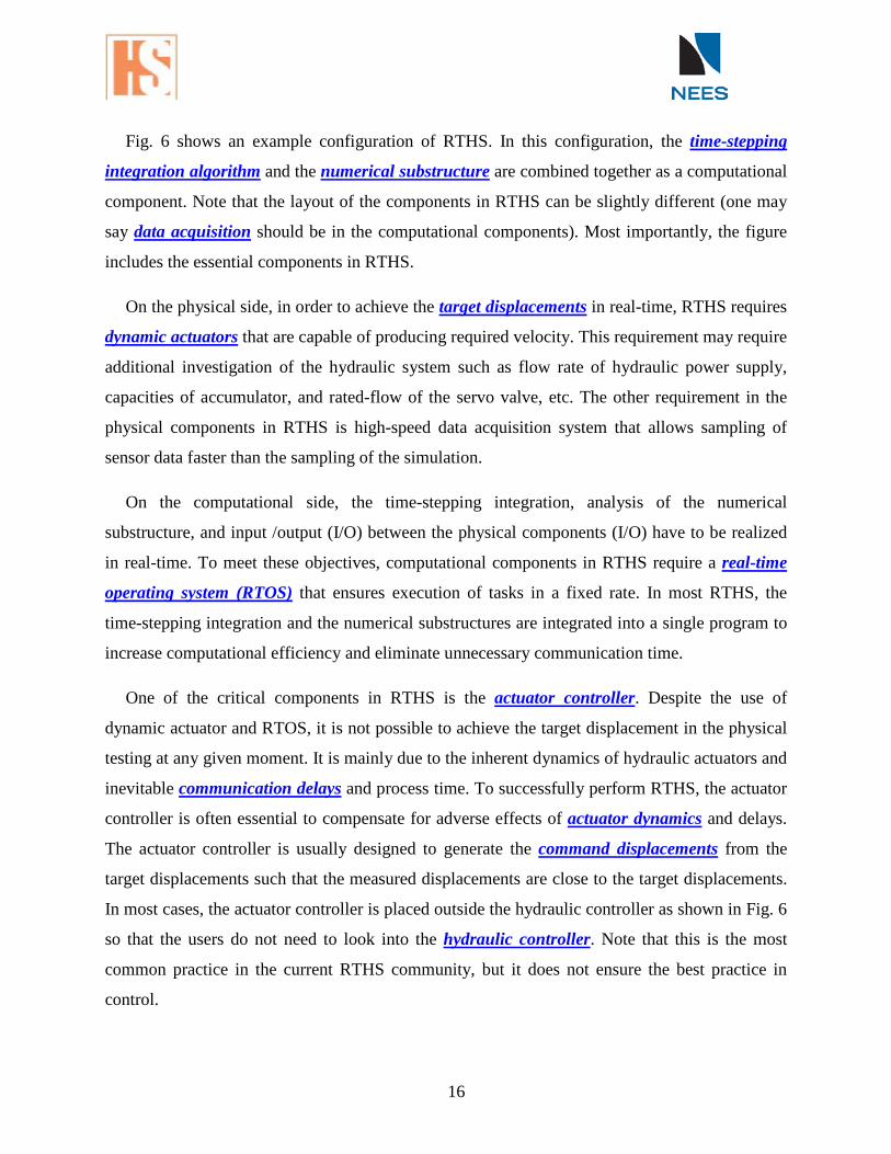
Fig. 6 shows an example configuration of RTHS. In this configuration, the time-stepping
integration algorithm and the numerical substructure are combined together as a computational
component. Note that the layout of the components in RTHS can be slightly different (one may
say data acquisition should be in the computational components). Most importantly, the figure
includes the essential components in RTHS.
On the physical side, in order to achieve the target displacements in real-time, RTHS requires
dynamic actuators that are capable of producing required velocity. This requirement may require
additional investigation of the hydraulic system such as flow rate of hydraulic power supply,
capacities of accumulator, and rated-flow of the servo valve, etc. The other requirement in the
physical components in RTHS is high-speed data acquisition system that allows sampling of
sensor data faster than the sampling of the simulation.
On the computational side, the time-stepping integration, analysis of the numerical
substructure, and input /output (I/O) between the physical components (I/O) have to be realized
in real-time. To meet these objectives, computational components in RTHS require a real-time
operating system (RTOS) that ensures execution of tasks in a fixed rate. In most RTHS, the
time-stepping integration and the numerical substructures are integrated into a single program to
increase computational efficiency and eliminate unnecessary communication time.
One of the critical components in RTHS is the actuator controller. Despite the use of
dynamic actuator and RTOS, it is not possible to achieve the target displacement in the physical
testing at any given moment. It is mainly due to the inherent dynamics of hydraulic actuators and
inevitable communication delays and process time. To successfully perform RTHS, the actuator
controller is often essential to compensate for adverse effects of actuator dynamics and delays.
The actuator controller is usually designed to generate the command displacements from the
target displacements such that the measured displacements are close to the target displacements.
In most cases, the actuator controller is placed outside the hydraulic controller as shown in Fig. 6
so that the users do not need to look into the hydraulic controller. Note that this is the most
common practice in the current RTHS community, but it does not ensure the best practice in
control.
16
In addition to the basics of RTHS presented above, some remarks on RTHS are listed below.
• RTHS has an enormous potential as an enabling technology for efficient and cost-
effective means of seismic performance evaluation of structural systems. Furthermore,
RTHS can be expanded to enhance capabilities in structural testing. Examples of those
include, but are not limited to, substructure shake table testing, dynamic force control
testing, and soil-structure interaction testing, etc.
• There are numerous ways to configure RTHS, probably more than hybrid simulation.
When it comes to setup an RTHS system, it is advised to review the specifications of
available equipment and the required functionalities to meet the needs prior to a selection
of tools, equipment and software. Be aware that not a single configuration satisfies all the
needs in RTHS.
• Significant research in RTHS has been made toward the development of actuator
controllers and time-stepping integration algorithms in recent years. Establishing best
practices toward acceptance criteria for those developments are currently in progress by
the NEES Hybrid Simulation Task Force. Interested users are recommended to frequently
check ‘Acceptance Criteria in RTHS’ at NEEShub.
5 Summary
This document presents a brief introduction of hybrid simulation and real-time hybrid
simulation including procedures and components. It is intended to help new users get a better
understanding of hybrid simulation, identify the proper type of hybrid simulation for their
research, and conduct hybrid simulation for their research needs. The Hybrid Simulation Task
Force will continue to make efforts to provide support for new users. We welcome feedback and
suggestions to improve this document.
17
6 Terminology
Actuator controller
A controller that receives the target displacement from the master simulation / simulation
coordinator and sends the command displacement to the hydraulic controller. Actuator
controller is necessary in most RTHS and is designed to compensate for actuator dynamics
and communication delay.
Synonyms: actuator compensator, delay compensation
Actuator dynamics
A hydraulic actuator is an electro-magnetic-mechanical device that has inherent complex
dynamics. Actuator dynamics has a large influence on the accuracy in real-time hybrid
simulation.
Analytical models
Representation of structure including mass, damping, stiffness and behavior in a
mathematical form
Synonyms: numerical model, computational model
Command displacement
Displacement command that is sent to the controller of hydraulic actuator to achieve target
displacement. In real-time hybrid simulation, command displacement is often different
from target displacement to compensate for dynamics of hydraulic actuator.
Communication delay
Time and associated delay to complete digital and analog process as well as
communication and exchange data between machines, software and hardware, analog and
digital in real-time hybrid simulation.
Synonyms: process delay, time delay
Computational component
Computer programs, numerical models and digital processes that are required in order to
perform hybrid simulation. Computational components include the time-stepping
integration algorithm, analysis of numerical substructure, communication and more.
18

Synonyms: numerical component
Conventional hybrid simulation
A family of hybrid simulation where the target displacement in experimental substructure
is imposed in a ramp-and-hold fashion. In general, actual test takes much longer than the
simulation time.
Synonyms: conventional slow-speed pseudodynamic test
Data acquisition
A device/equipment that converts analog signals from transducers into digital data. Hybrid
simulation requires a data acquisition that has communication capabilities and data storage.
Discrete parameter system
A system of which behavior is represented by a finite number of parameters at discrete
points. Hybrid simulation is based on the equation of motion of discrete parameter system.
Dynamic actuator
A hydraulic actuator with dynamic loading capabilities. The dynamic actuator is usually
equipped with a servo valve. It also requires a certain level of hydraulic oil flow and
accumulators to prevent pressure drop.
Equation of motion
An underlying mathematical formula of the dynamics of structure, which is in the second-
order differential equation. Hybrid simulation is based on the solution of EOM in a time-
stepping manner.
Acronyms: EOM
Experimental substructure
A part of the structural model in hybrid simulation that is physically modeled and
experimentally tested in laboratory.
Synonyms: physical substructure, experimental module
External input
19
Most of the commercial hydraulic controllers take an external input to drive actuator. In
hybrid simulation, the command displacement is sent to hydraulic controller through an
external input port. The input port can be either digital or analog.
Synonyms: external reference, external set point
Geographically distributed hybrid simulation
A family of hybrid simulation where the process of one or more of experimental and
numerical substructures are performed at remote site.
Hybrid simulation
A simulation technique that combines physical experimentation with computational
simulation via a communication exchange to evaluate how structures and lifelines respond
to simulated earthquakes.
Synonyms: hybrid testing, pseudodynamic testing, online testing, internet-based
simulation, dynamic structure testing
Acronyms: HS, HT PSD
Hydraulic actuator
A mechanical device to impose controlled loading to test specimen, powered by
pressurized hydraulic fluid. It usually requires a closed-loop feedback control system with
a position sensor and a servo valve for high-precision control.
Synonyms: transfer system
Hydraulic controller
An inner-loop servo controller for hydraulic actuator. Most commercial hydraulic
controllers are PID (proportional-integral-differential) controller.
Synonyms: inner-loop controller
Master model
An analytical model for the whole structure that includes individual models of both the
computational and experimental substructures.
Master simulation / Simulation coordinator
20
Computational process that solves equation of motion and handles communication with
experimental and numerical substructures. Structural parameters such as mass, damping
and stiffness are stored in the master simulation / simulation coordinator.
Measured force
Force that is measured from the experimental substructure when the target displacement is
imposed.
Numerical simulation
A simulation technique to obtain seismic response of structural systems using only
numerical models.
Synonyms: computational simulation
Numerical substructure
A part of the structural model in hybrid simulation that is numerically modeled and
simulated in computational software.
Synonyms: computational substructure, analytical module
Physical component
Physical/laboratory equipment, elements, and devices that are required in order to impose
the target displacements and extract the restoring forces in experimental substructure.
Physical components include physical specimen, hydraulic actuator, hydraulic controller,
data acquisition, sensors, and other laboratory equipment.
Synonyms: experimental component
Physical specimen
Physical model that represents a part of structural system. It is experimentally tested and
measured in laboratory.
Quasi-static testing
An experimental technique to obtain stress-strain or displacement-force relations of the
physical specimen. Input is usually a pre-specified protocol such as triangle input, and the
loading is imposed in a slow speed to avoid inertial effects in the measurement.
Real-time hybrid simulation
21

A family of hybrid simulation where the entire processes of hybrid simulation are
performed at the true rate of the simulation. It is particularly advantageous for the
simulation of systems with rate-dependent components in the experimental structure.
Synonyms: real-time pseudodynamic test, dynamic substructuring test
Acronyms: RTHS, RTHT
Real-time operating system
An operating system that is designed to execute requests in a deterministically small time
window. RTOS is an essential piece of equipment/hardware in real-time hybrid simulation.
Acronyms: RTOS
Restoring force
Force that corresponds to the target displacement in hybrid simulation.
Synonyms: measured force, simulated force, interface force
Sensor / Transducer
A device/equipment that provides digital or analog signals that corresponds to physical
measurements. Most traditional sensors in hybrid simulation are analog and their signals
are processed in data acquisition.
Servo hydraulic system
A system that consists of hydraulic actuator, service-manifold, hydraulic power supply,
and a hydraulic controller
Synonyms: transfer system
Simulated force
Numerically simulated force that represents the restoring force from the numerical
substructure when the target displacement is applied.
Simulation time
Period of the earthquake ground motion in hybrid simulation. The simulation time is not
always equal to the actual time of testing. In RTHS, simulation time is the same as the
actual testing time.
Strain-rate dependent
22
A term used to describe structural materials and members of which behavior is dependent
on the rate of loading. Examples are viscous dampers, rubber bearings, etc.
Target displacement
Prescribed displacement obtained from solution of equation of motion using a time-step
integration algorithm. Target displacements are sent to experimental and numerical
substructures at every step in hybrid simulation.
Synonyms: reference displacement, desired displacement
Time-stepping integration algorithm
A technique to solve the discretized equation of motion for the target displacement. Most
integration methods calculate the target displacements from system parameters (e.g., mass,
damping and stiffness), past response states, and restoring forces.
Synonyms: integration method, solver
23