hybrid + quick start guide version 1web.carlsonsw.com/.../hybrid-quick-start-guide.pdf ·...
TRANSCRIPT

Hybrid +
Quick Start Guide
Version 1.00
Table of Contents
1 Hybrid+ Setup .................................................................................................................................................. 3
1.1 Setup Method 1: Hybrid+ Setup Using Grid Coordinates ........................................................................................................ 3
1.2 Setup Method 2: Hybrid+ Setup Using Known Local Coordinates .......................................................................................... 9
2 Using Hybrid+ ................................................................................................................................................ 16
3 Hybrid+ Features and Settings ...................................................................................................................... 17
4 Exiting Hybrid+............................................................................................................................................... 19

Page | 3
1 Hybrid+ Setup
Hybrid+ allows the use of a robotic total station and GPS receiver simultaneously to increase survey reliability and efficiency. The
Hybrid+ setup wizard is designed to step you through configuration of Hybrid+, allowing multiple setup options based on user
preference. This quick start guide will walk you through two methods of setup and explain the basics of Hybrid+.
1.1 Setup Method 1: Hybrid+ Setup Using Grid Coordinates
Use this setup method if you run a GPS receiver on grid coordinates and would like to configure your robotic total station to run on
grid coordinates.
Begin by configuring a GPS Receiver as you normally would, setting up RTK corrections and achieving a fixed position using either
a radio or network connection.
To enter Hybrid+ mode, tap the quick-switch instrument selector in the top bar of the main menu. Select Hybrid +. Click yes when
prompted “Switch to Hybrid Survey Mode?” If you have not registered the Hybrid+ module, you will be prompted to temporarily
enter demo mode to try Hybrid+. You can revert to your full registered copy at any time by exiting and reentering the software.
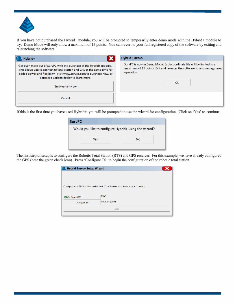
If you have not purchased the Hybrid+ module, you will be prompted to temporarily enter demo mode with the Hybrid+ module to
try. Demo Mode will only allow a maximum of 15 points. You can revert to your full registered copy of the software by exiting and
relaunching the software.
If this is the first time you have used Hybrid+, you will be prompted to use the wizard for configuration. Click on ‘Yes’ to continue.
The first step of setup is to configure the Robotic Total Station (RTS) and GPS receiver. For this example, we have already configured
the GPS (note the green check icon). Press ‘Configure TS’ to begin the configuration of the robotic total station.

Page | 5
Configure the robotic total station as you normally would.
Press the green check to connect and return to the wizard. Both buttons should now have a green check to indicate the instruments
are configured. Press ‘Next’ to continue.
Next, the wizard will guide you through setting your GPS and RTS heights. Measure the height of the prism (from the tip of the pole
to the center of the prism) and measure the height of the GPS receiver (from the found to the reference mark on the antenna, slant or
vertical). Enter in these values in the screen.
The software will now calculate the fixed offset between the center of the prism and the GPS receiver. From this point forward,
changing either height (GPS or RTS) will automatically adjust the other using this fixed offset value. Press ‘Next’ to continue.

To survey in Hybrid+ mode, it is necessary to ensure the robotic total station and GPS are measuring points on the same coordinate
system. The next step in the wizard will address this. In this example, we will configure the robotic total station to use state plane
grid coordinates using the Hybrid Resection procedure.
In order for coordinates to match over long distances, it is necessary to scale either the robotic total station or GPS measurements,
Select your scaling method. In this example, we are using ‘Scale TS (Ground to Grid)’. Click ‘Next’ to continue.
The next screen will allow the Hybrid Resection procedure to begin. When ready, click on ‘Perform Hybrid Resection’ to continue.

Page | 7
It is not necessary to have any known coordinates to perform a hybrid resection. The known points will be measured from the GPS
receiver. Simply aim the total station to the prism and press ‘Read Hybrid Position’ to measure a resection point. The software will
measure the total station position and the GPS position at the same time, synchronizing the readings automatically by time. You will
be prompted to store the resection point if you desire. Move to a new location and repeat.
When you are satisfied with your resection, press ‘Calculate’ to view your results and store the calculated position of the robotic total
station. The software will then set the orientation angle on the robotic total station and return to the wizard.
The next step is to ‘Perform a Cross-Check’. Cross-check will measure a position simultaneously using the robotic total station and
GPS receiver. It will then compare the coordinates match based on the displayed tolerances.
Cross-check tolerances can be augmented within this screen. Perform a Cross-check by pressing ‘Perform Cross-Check’.
Once setup is complete, the software will use these tolerances to detect any unacceptable deviations between the RTS and GPS
positions. If an unacceptable deviation is present, a warning screen will pop-up to warn the field engineer.

Setup is now complete. Press ‘Finish’ to exit the wizard and begin using Hybrid+.

Page | 9
1.2 Setup Method 2: Hybrid+ Setup Using Known Local Coordinates
Use this method if you typically run a robotic total station on ground coordinates and want to localize the GPS receiver to ground
coordinates.
Begin by configuring a robotic total station (RTS) normally, configuring the instrument and setting your backsight and orientation.
To enter Hybrid+ mode, tap the quick-switch instrument selector in the top bar of the main menu. Select Hybrid+.
If you have not purchased the Hybrid+ module, you will be prompted to temporarily enter demo mode with the Hybrid+ module to
try. Demo Mode will only allow a maximum of 15 points. You can revert to your full registered copy of the software by exiting and
relaunching the software.

If this is the first time you have used Hybrid+, you will be prompted to use the wizard for configuration. Click on ‘Yes’ to continue.
The first step of setup is to configure the Robotic Total Station (RTS) and GPS receiver. For this example, we have already configured
the robotic total station (note the green check icon). Press ‘Configure GPS’ to begin the configuration of the GPS receiver.
Configure the GPS as you normally would, ensuring a valid RTK correction link. Once the GPS receiver is configured, both buttons
will show green check icons. Press ‘Next’ to continue.
Next, the wizard will guide you through setting your GPS and RTS heights. Measure the height of the prism (from the tip of the pole
to the center of the prism) and measure the height of the GPS receiver (from the ground to the reference mark on the antenna, slant or
vertical). Enter in these values in the screen.

Page | 11
The software will now calculate the fixed offset between the center of the prism and the GPS receiver. From this point forward,
changing either height (GPS or RTS) will automatically adjust the other using this fixed offset value. Press ‘Next’ to continue.
To survey in Hybrid+ mode, it is necessary to ensure the robotic total station and GPS are measuring points on the same coordinate
system. The next step in the wizard will address this. In this example, we will configure the GPS receiver to existing ground
coordinates using the ‘Use Localization’ procedure. Select ‘Use Localization’ and click ‘Next’ to continue.
There are two methods of performing the localization for Hybrid+, localize manually and auto-localize. Localize Manually will
proceed to the SurvCE localization screen where a localization may be created by measuring individual points and adding them to the
localization. Auto-Localize will proceed to the Store Points screen and switch the active instrument to the robotic total station. The
auto-localization will complete once enough points are measured.

We will run an example of the Auto-Localization method below. Select ‘Auto Localize’ and click ‘Next’ to continue.
The setup wizard will now complete. However, no points have been measured and a Cross-check has not been performed, so Hybrid+
is not yet fully active.
Click on ‘Finish’ to exit the Hybrid+ Setup Wizard. SurvCE will now automatically set the active instrument to the robotic total
station. It will not be possible to switch to GPS mode until enough points are measured with the robotic total station to form a good
auto localization. From the main menu, select Survey – Store Points. The Store points routine will be used to form an auto-localization.
Within the Store Points screen, each time a point is stored with the robotic total station, the GPS measurement is collected at the same
time. A localization will be formed in the background by analyzing all measurements pairs and selecting the best quality
measurements.

Page | 13
The status of the auto localization can be viewed at any time by selecting Equip – Configure – Hybrid tab.
The screen shot above reflects the status of an Auto Localization routine before any points are stored. When enough points are stored
the Auto Localization status will switch from ‘Insufficient Points [0]’.
Before the Auto Localization is complete, an attempted switch to GPS mode will be blocked by the software with a warning message.
Use the robotic total station to store several points. An ideal localization will form a triangle around the robotic total station, but it is
not necessary to intentionally from a localization. The software will calculate the best localization continuously. When an auto
localization is calculated, features like Smart Lock, Follow Me, and GPS Search will be enabled, based on user settings. Once the auto
localization is complete, a switch to GPS mode using the instrument status icon can be made. At that time, the auto localization will
be finalized and no further localization points will be collected. Press the quick switch icon to switch to GPS Mode.
Press ‘Yes’ to finalize. SurvCE will proceed to the Localization screen.

From this screen, you can review your localization points and quality as you would a manual localization.
Press the green check to finalize the auto localization routine. With the localization complete, the next step is to perform a Cross-
Check. The software will direct the user to the cross-check procedure automatically.
Click ‘Yes’ to perform a cross check. The Cross-check procedure will measure a position simultaneously using the robotic total station
and GPS receiver and verify that the coordinates match. If the coordinates match within tolerances, the localization is good and the
robotic total station and GPS receiver are on a matching coordinate system. Hybrid+ setup is complete.
Tolerances can be adjusted in the Hybrid tab of Equip – Configure. Once setup is complete, SurvCE will use these tolerances to detect
unacceptable deviations between the robotic total station and GPS positions. Unacceptable deviations will be shown as a warning to
the user throughout the survey session.

Page | 15
Setup is now complete. Press ‘Finish’ to exit the wizard and begin using Hybrid+.

2 Using Hybrid+
Once Hybrid+ is active, SurvCE can be used normally. The new Instrument Status icon, shown on the upper-left of the screen, will
indicate the status of the configured instruments at all times. The checkmark (shown below the instrument icon) will indicate the
active instrument. While both the robotic total station and GPS receiver are connected and may be measuring at any time, the active
instrument will control the options available in the main menu along with the display in active survey screens. The color on each side
of the Instrument Status icon indicates the status of position quality.
Red: The instrument is not connected.
Yellow: The instrument is connected but an accurate position is unavailable.
• Yellow for GPS: Receiver mode is not Fixed RTK. (Receiver mode is Autonomous, DGPS, RTK Float, etc..).
• Yellow for Robotic Total Station: Standby or lost prism.
Green: The instrument is connected and an accurate position is available.
• Green for GPS: Receiver mode is Fixed RTK.
• Green for Robotic Total Station: Locked / Tracking.
Note: The Instrument Status icon shown above is displaying the robotic total station as active. The yellow color indicates it is not currently tracking a prism. The
GPS icon is green, indicating the current Fixed RTK status.
The instrument status icon can be selected from any screen to quickly switch active survey modes. When the GPS instrument is active,
the menus and display of SurvCE will be in GPS mode. When the robotic total station instrument is active, the menus and display of
SurvCE will be in total station mode.
Note: Menus shown in GPS mode.
Note: Menus shown in Total Station mode. Check Level and TS Utilities are shown in the main menu.

Page | 17
3 Hybrid+ Features and Settings
Hybrid+ settings can be accessed from the main menu by selecting Equip – Configure and navigating to the Hybrid tab.
The Hybrid tab allows editing / viewing several settings.
• Antenna / Prism Height: The Antenna and Prism Heights can be viewed and/or edited. Updating either height elsewhere in the
software will automatically adjust the other.
• Cross-Check Status: The Cross-Check Status is shown – this will inform if any recently compared GPS and robotic total station
points have been compared successfully. The screen shot above indicates Cross-Check has not yet completed. If localization has
been used, the auto localization status and/or other localization information will be visible under the Cross-Check Status.
• Ignore GPS Search Elv: GPS Search is always available when Hybrid+ is active. To use it, select the down arrow to the right
of the search icon from any active screen, and select ‘GPS Search’.
In locations where the GPS cannot get a quality position and elevations are relatively flat, it may be useful to ignore the less
accurate elevation measurement of the GPS receiver and still perform GPS searches using only the horizontal position to locate
the prism. Enable ‘Ignore GPS Search Elv’ to do this.
• Require Cross-Check on Store: Enable this option to force the software to calculate a cross-check on every stored point. When
enabled, this option will affect workflow based on mode.
o In GPS Mode: If the robotic total station is not locked on the prism, a search will be performed.
o In Robotic Total Station Mode: If the GPS is not Fixed RTK, the user will be warned. Note: Only the active instrument’s measurements will be stored in the RW5 file.
This option forces the software to check both instrument positions for each stored point, allowing the user to see a warning if
either instrument’s position is sub-optimal.
• Backup Tracking: When Backup Tracking is enabled, SurvCE will automatically display the backup (and inactive) instrument
position on the screen when the primary (and active) instrument’s position is unavailable. The backup instrument position will
be displayed in red. This means if the robotic total station is active, and the E.D.M. is obstructed, the software will display the
GPS position in the bottom bar as well as the GPS location triangle until the robotic total station position is restored.
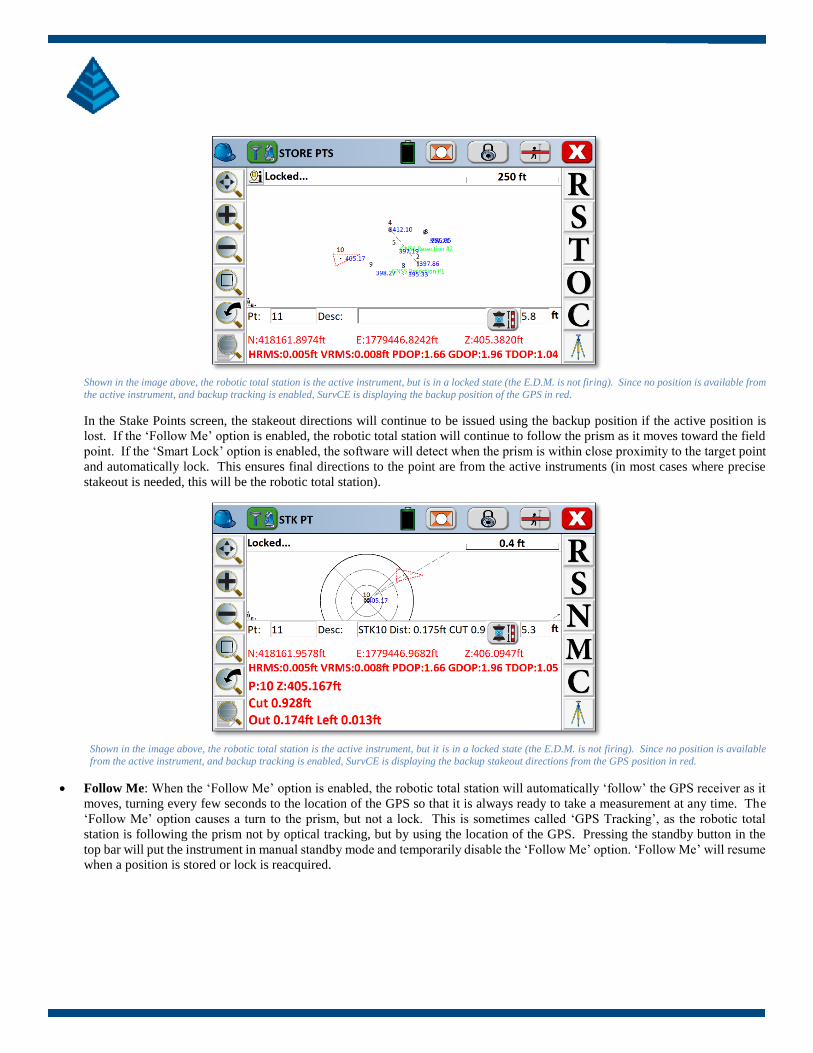
Shown in the image above, the robotic total station is the active instrument, but is in a locked state (the E.D.M. is not firing). Since no position is available from
the active instrument, and backup tracking is enabled, SurvCE is displaying the backup position of the GPS in red.
In the Stake Points screen, the stakeout directions will continue to be issued using the backup position if the active position is
lost. If the ‘Follow Me’ option is enabled, the robotic total station will continue to follow the prism as it moves toward the field
point. If the ‘Smart Lock’ option is enabled, the software will detect when the prism is within close proximity to the target point
and automatically lock. This ensures final directions to the point are from the active instruments (in most cases where precise
stakeout is needed, this will be the robotic total station).
Shown in the image above, the robotic total station is the active instrument, but it is in a locked state (the E.D.M. is not firing). Since no position is available
from the active instrument, and backup tracking is enabled, SurvCE is displaying the backup stakeout directions from the GPS position in red.
• Follow Me: When the ‘Follow Me’ option is enabled, the robotic total station will automatically ‘follow’ the GPS receiver as it
moves, turning every few seconds to the location of the GPS so that it is always ready to take a measurement at any time. The
‘Follow Me’ option causes a turn to the prism, but not a lock. This is sometimes called ‘GPS Tracking’, as the robotic total
station is following the prism not by optical tracking, but by using the location of the GPS. Pressing the standby button in the
top bar will put the instrument in manual standby mode and temporarily disable the ‘Follow Me’ option. ‘Follow Me’ will resume
when a position is stored or lock is reacquired.

Page | 19
• Backup Storing: When the ‘Backup Storing’ option is enabled, the backup position will be stored when the primary (and active)
instrument’s position is unavailable. For more manual control, leave this option disabled, and simply tap the quick-switch icon
in the top bar to switch to the active instrument and store the position.
• Smart Lock: When the ‘Smart Lock’ option is enabled, the software will monitor the motion of the GPS. When the movement
of the GPS slows (i.e. the surveyor is slowing to take a measurement), the robotic total station will rotate to the prism and optically
lock on to the prism. ‘Smart Lock’ can operate by itself, or in conjunction with ‘Follow Me’. If the software detects further
movements of the GPS while attempting to lock, the Smart Lock routine will cancel automatically in the background. Pressing
the standby button in the top bar will put the instrument in manual standby mode and temporarily disable Smart Lock. Smart
Lock will resume when a position is stored or lock is reacquired.
• IMU: Hybrid+ can take full advantage of tilt sensors on the GPS receiver by applying them to both the robotic total station and
the GPS.
• When IMU is enabled during Hybrid+:
o The tilt sensors of the GPS receiver can be used to adjust the measurements of the robotic total station prism. This
is true even when the GPS receiver is not Fixed RTK.
o The digital level bubble can display in active survey screens even when the robotic total station is the active
instrument.
o SurvCE can warn the user when the robotic total station measurements are outside of level tolerance.
4 Exiting Hybrid+
Hybrid+ mode will end automatically when SurvCE is exited, or a new job is started. Alternatively, a return to normal survey mode
can be made by selecting any other survey mode using the quick switch icon in the main menu.