hybrid pdms testing and techno-economic model
TRANSCRIPT

the ENERGY lab
Nicholas Siefert
Hybrid PDMS Testing and Techno-economic Model
Task Technical Coordinator Pre-combustion Solvents NETL CO2 Capture Conference
8/1/2014
Team Members: Sweta Agarwal, Hunaid Nulwala, Elliot Roth, Fan Shi, Wei Shi, David Miller, Dave Hopkinson, Bob Enick, John Kitchin, and Dave Luebke

• Overall goal of project • Experimental Data on Pre-combustion Solvents • Discussion of Process Flow Diagram • Capital & Operating Cost Breakdown of Equipment • Economic Model / Levelized Cost Estimate • Future work
Outline
2
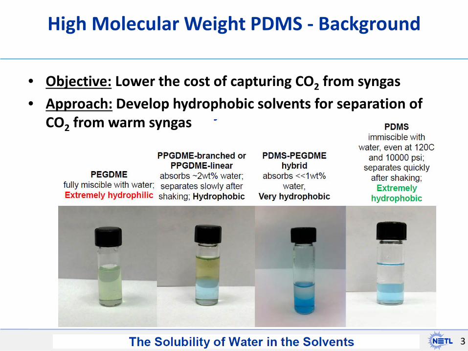
• Objective: Lower the cost of capturing CO2 from syngas • Approach: Develop hydrophobic solvents for separation of
CO2 from warm syngas
High Molecular Weight PDMS - Background
3

• Higher CO2 and H2S selectivity against H2 at lower temperature
• Constraint: Selexol will absorb any remaining water in syngas
Background: Why Selexol must operate < 40oC
4
0%10%20%30%40%50%60%70%80%90%
100%
40 90 140 190Syngas Temperature [°C]
Water Remaining in Syngas vs. Temperature

Experimental Results
5

Selexol vs. Hybrid @25oC
• Hydrophilic • Viscosity = 5.8 cP • MW = 280 • Specific heat = 2.06 kJ/kg∙K • Density = 1030 kg/m3
• Thermal cond = 0.19 W/m∙K • Surface tension ~ 32 mN/m • Vapor Pressure = 0.0007
mmHg • CO2/H2 selectivity ~ 80
• Hydrophobic • Viscosity = 4.8 cP • MW = 438 • Specific heat = 1.77 kJ/kg∙K • Density ~ 936 kg/m3
• Thermal cond = TBD* • Surface tension = 22.1 mN/m • Vapor Pressure << 0.0007
mmHg • CO2/H2 selectivity ~ 40
Selexol *AspenPlus estimates that the thermal conductivity is 0.10 W/m∙K

0
2
4
6
8
10
12
14
16
18
20
22
0 5 10 15 20 25 30 35 40
CO2 S
olub
ility
(w
t% in
clud
ing
CO2)
CO2 Partial Pressure (bar-a)
CO2 Solubility in Hybrid-PDMS 25°C
Experimental NETL
Experimental U. Pitt
Experimental NCCC
ComputationalSimulation NETL

0
50
100
150
200
250
300
0 5 10 15 20 25 30 35
H2 S
olub
ility
(pp
m w
t)
H2 Partial Pressure (bar-a)
H2 Solubility in Hybrid-PDMS 25°C and 40°C
Experimental NETL 25CExperimental NETL 40CExperimental U. Pitt 25CExperimental U. Pitt 40CComputational NETL 25CComputational NETL 40C

• 8 L of Hybrid PDMS-PEGDME were synthesized at NETL and shipped to NCCC
• Hybrid solvent was tested for CO2 solubility at 20oC and 40oC
• Solvent had tendency to foam and create fine aerosols at higher temperatures – Due to low surface tension,
low viscosity, and low density – Increases absorber diameter,
but can decrease height
9
PDMS Scale up & NCCC Testing

Selexol vs. Ionic Liquid @25oC
• Hydrophilic • Viscosity = 5.8 cP • MW = 280 • Specific heat = 2.06 kJ/kg∙K • Density = 1030 kg/m3
• Thermal cond = 0.19 W/m∙K • Surface tension ~ 32 mN/m • Vapor Pressure = 0.0007
mmHg • CO2/H2 selectivity ~ 80
• Hydrophobic (0.23 wt% H2O) • Viscosity = 28 cP (wet) • MW = 399 • Specific heat = 1.11 kJ/kg∙K • Density ~ 1515 kg/m3
• Thermal cond = TBD* • Surface tension = TBD* • Vapor Pressure <<< 0.0007
mmHg • CO2/H2 selectivity ~ 150
Selexol
Ionic Liquid Selexol

0
0.2
0.4
0.6
0.8
1
1.2
1.4
1.6
1.8
0 2 4 6 8 10 12 14 16Conc
entr
atio
n (m
ol C
O2
/ L
Nea
t Sol
vent
)
Partial Pressure (bar)
Ionic Liquid
H-PDMS
Selexol
CO2 Solubility at 25oC in different Solvents

0
0.01
0.02
0.03
0.04
0.05
0.06
0.07
0.08
0.09
0 5 10 15 20 25 30
Conc
entr
atio
n (m
ol H
2/L
Solv
ent)
Partial Pressure (bar)
Ionic Liquid
H-PDMS
Selexol
H2 Solubility at 25oC

System Modeling
13

System Modeling: Data Regression in Aspen Plus
• Data Regression to estimate the required pure and binary parameters
• Regression requires input of both thermodynamic & kinetic variable
14
• PC-SAFT method used for H-PDMS and Selexol
• ENRTL-RK method used for Ionic Liquid

System Modeling: Aspen Plus Modeling
• Model for Physical Solvent based CO2 capture using flash regeneration adapted from MIT IGCC-Selexol capture Aspen Model
15 Field and Brasington, “Baseline Flowsheet Model for IGCC with Carbon Capture,” Ind. Eng. Chem. Res., 2011, 50 (19), p 11306.
Rate-based Absorber
HP Flash-Recycle
Pressure Swing Regeneration
Solvent Chiller

System Modeling: Aspen Plus Modeling
• Base Model for CO2 capture using flash regeneration adapted from MIT IGCC-Selexol capture Aspen Model
16
Field and Brasington, “Baseline Flowsheet Model for IGCC with Carbon Capture,” Ind. Eng. Chem. Res., 2011, 50 (19), p 11306.

Our Economic Model
• Economic Model Assumptions: – There is an existing IGCC Power Plant with H2S Removal – 1 Years for Construction (for CO2 Capture Equipment) – 30 Years of Operations with O&M = 4% of Capital per year – 80% Capacity Factor – 5% Inflation-Adjusted Interest Rate – Plant Cost Ratio = 5 = Total Capital Cost / Bare Equipment Costs – Bare Capital Cost estimates calculated from equations taken
from various sources (Sieder Textbook, AspenPlus, IECM) • Used to calculate the levelized cost of capturing CO2
– Levelized cost = Operating costs plus capital costs levelized per ton of CO2 captured
– Values are normalized compared with Selexol

Operating Cost Incurred due to lower power
genreation 34.7%
Operating Cost Incurred due to lost H2
1.3% CO2 Compression
Operating Cost 19.5%
Solvent Based CO2 Capture
Operating Cost 10%
Fixed O&M 13.8%
CO2 Compression Capital Cost
9.7%
Solvent based CO2 Capture Capital Cost
10%
WGS Capital Cost 1.8%
Operating & Levelized Capital Cost Distribution Chart: Selexol Normalized
Value = 1.00 For Levelized Cost per CO2 Captured
Note: Levelized Cost at 10°C was less than 40°C

0.0
0.2
0.4
0.6
0.8
1.0
H-PDMS (10°C) Selexol (10°C) NETL Ionic Liquid(40°C)
Nor
mal
ized
Leve
lized
Cos
t of C
aptu
ring
CO2
Comparison of Levelized Cost of Capture
Fixed O&M Cost
Levelized WGS, Captureand Compression CapitalCost
Capture Operating Cost
Compression OperatingCost
Gas not going to BraytonCycle Penalty Cost

Future Work
• Test Ionic Liquid Solvent at NCCC, and continue testing at NETL
• H2S testing for both H-PDMS and Ionic Liquid
• Model both H-PDMS and Ionic Liquid in a full IGCC-CCS system model with two-stage H2S/CO2 removal
• Include H2 & H2O separating membrane upstream of two-stage H2S/CO2 removal in order to potentially lower the levelized cost even further
20

• Thanks to: NETL SCC, Sweta Agarwal, Hunaid Nulwala, Elliot Roth, Fan Shi, Wei Shi, Regina Woloshun, David Miller, Dave Hopkinson, Bob Enick, John Kitchin, and Dave Luebke
Thank You
Back-up Slides

Glossary
PC-SAFT : Perturbed Chain statistical associating fluid theory NRTL: Non-random two-liquid ENRTL-RK: Electrolyte NRTL with Redlich Kwong vapor phase properties

System Modeling: Preliminary Results of Net Power Consumed

Enick et al., “Hydrophobic polymeric solvents for the selective absorption of CO2 from Warm Gas Stream that also contain H2 and H2O,” CCUS Conference, Pittsburgh, PA, May 15 2013

Enick et al., “Hydrophobic polymeric solvents for the selective absorption of CO2 from Warm Gas Stream that also contain H2 and H2O,” CCUS Conference, Pittsburgh, PA, May 15 2013

PDMS Solubility using Raman: Dr. Kitchin CMU
CO2
H2 • CO2 and H2 Raman
spectroscopy can be used to determine solubility
CO2 and H2 Raman spectroscopy can be used to determine selectivity

Absorber: $11M
Flash Units & Separator: $1.5M
Bare Equipment Costs: H-PDMS
Recycle Compressor and Cooler : $2M
Solvent Pump: $0.5M
Solvent Chiller: $4M

Bare Equipment Costs: CO2 Compression Cycle
150 atm liquid CO2 21 atm 80 atm
11 atm
Cost of LP Compressor and Intercooler: $4.5M
Cost of MP, HP Compressors, Intercoolers and Liquid CO2 Pump: $12.7M

Operating Cost Incurred due to lower power
genreation 35.4%
Operating Cost Incurred due to lost H2
1.4%
CO2 Compression Operating Cost
18.8%
Solvent Based CO2 Capture
Operating Cost 10%
Fixed O&M 13.6%
CO2 Compression Capital Cost
9.0%
Solvent based CO2 Capture Capital Cost
10%
WGS Capital Cost 1.9%
Levelized Cost Distribution Chart: H-PDMS

Operating Cost Incurred due to lower power
genreation 35.4%
Operating Cost Incurred due to lost H2
1.4%
CO2 Compression Operating Cost
18.8%
Solvent Based CO2 Capture
Operating Cost 10%
Fixed O&M 13.6%
CO2 Compression Capital Cost
9.0%
Solvent based CO2 Capture Capital Cost
10%
WGS Capital Cost 1.9%
Levelized Cost Distribution Chart: H-PDMS Normalized to
Selexol, Levelized Cost per CO2 Captured = 0.98 +/-0.07 Uncertainty reflects uncertainty in CO2&H2 Solubility as measured by different researchers
Note: Levelized Cost at 10°C was less than 40°C

Operating Cost Incurred due to lower power
genreation 43.1%
Operating Cost Incurred due to lost H2
0.2%
CO2 Compression Operating Cost
22.5%
Solvent Based CO2 Capture
Operating Cost 10%
Fixed O&M 11.3%
CO2 Compression Capital Cost
10.9%
Solvent based CO2 Capture Capital Cost
10%
WGS Capital Cost 2.3%
Levelized Cost Distribution Chart: NETL Ionic Liquid Normalized to
Selexol, Levelized Cost per CO2 Captured = 0.79 +/-0.04 Uncertainty reflects uncertainty in H2 Solubility
Note: Levelized Cost at 40°C was less than 10°C