humitity temperature meter omeganette® - omega … · omegaette® hh314a humidity temperature...
TRANSCRIPT
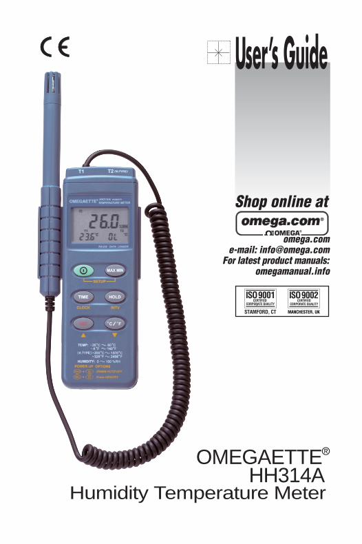
OMEGAETTE®
HH314AHumidity Temperature Meter
omega.com e-mail: [email protected]
For latest product manuals:omegamanual.info
User’s Guide
Shop online at
Servicing North America:USA: One Omega Drive, Box 4047ISO 9001 Certified Stamford CT 06907-0047
Tel: (203) 359-1660FAX: (203) 359-7700e-mail: [email protected]
Canada: 976 BergarLaval (Quebec) H7L 5A1, CanadaTel: (514) 856-6928FAX: (514) 856-6886e-mail: [email protected]
For immediate technical or application assistance:USA and Canada: Sales Service: 1-800-826-6342/1-800-TC-OMEGA®
Customer Service: 1-800-622-2378/1-800-622-BEST®
Engineering Service: 1-800-872-9436/1-800-USA-WHEN®
Mexico: En Espanol: (001) 203-359-7803FAX: ( 001) 203-359-7807e-mail: [email protected]@omega.com.mx
Servicing Europe:Czech Republic: Frystatska 184, 733 01 Karviná, Czech Republic
Tel: +420 (0)59 6311899FAX: +420 (0)59 6311114Toll Free: 0800-1-66342e-mail: [email protected]
Germany/Austria: Daimlerstrasse 26, D-75392 Deckenpfronn, GermanyTel: +49 (0)7056 9398-0FAX: +49 (0)7056 9398-29Toll Free in Germany: 0800 639 7678e-mail: [email protected]
United Kingdom: One Omega Drive, River Bend Technology CentreISO 9002 Certified Northbank, Irlam, Manchester
M44 5BD United Kingdom Tel: +44 (0)161 777 6611FAX: +44 (0)161 777 6622Toll Free in United Kingdom: 0800-488-488e-mail: [email protected]
OMEGAnet® Online Service Internet e-mailomega.com [email protected]
It is the policy of OMEGA to comply with all worldwide safety and EMC/EMI regulations that apply. OMEGA is constantly pursuing certification of its products to the European New ApproachDirectives. OMEGA will add the CE mark to every appropriate device upon certification.The information contained in this document is believed to be correct, but OMEGA Engineering, Inc. accepts no liability for any errors it contains, and reserves the right to alter specifications without notice.WARNING: These products are not designed for use in, and should not be used for, human applications.
CONTENTS
TITLE PAGE
I. Safety Information………………………………………………………………….….. 1 II. Introduction…...……………………………………………………………………….….. 1 III. Specifications………………………………………………………………………….. 1 IV. Symbol Definition and Button Location……………………………….. 2 V. Operation Instructions…………………………………………….…………..…… 3
4.1 Power-Up…………………………………………………………………………………..... 3 4.2 Humidity and Temperature Measurement…………………………………………...... 3 4.3 Connection the Thermocouples ( T2 channel )……………….……………………... 3 4.4 Selecting the Temperature Scale……………………………………………………….. 3 4.5 Data-Hold Operation………………………………………………………………………. 3 4.6 DataLogger…………………………………………………………………………………. 3 4.7 Clock Setup ………………………………………………………………………………... 4 4.8 Recording Interval Setup……..…………………………………………………………. 4 4.9 Time Operation…………….…………………………………………………………….... 4 4.10 MAX/MIN Operation………………………………………………………….……….…. 4 4.11 Auto Power Off………………………………………………………………………….… 5 4.12 Low Battery Condition ………………………………………………………………….. 5 4.13 Digital Output……………………………………………………………………………... 5
VI. Calibration Procedure…………………………………………………………….. 5 VII. Setup HH310-SW—RS232 interface software………………...… . 7
HH314A
1
I. Safety Information Read the following safety information carefully before attempting to operate or service the meter. Use the meter only as specified in this manual; otherwise, the protection provided by the meter may be impaired.
Environment conditions Altitude up to 2000 meters Relatively humidity 90% max. Operation Ambient 0 ~ 50°C
Maintenance & Clearing Repairs or servicing not covered in this manual should only be performed by qualified personnel. Periodically wipe the case with a dry cloth. Do not use abrasives or solvents on this instrument.
Safety symbols
Comply with EMC
Read safety Information first.
II. Introduction: This instrument is a digital Humidity/Temperature meter that uses a polymer capacitive and semiconductor sensor and K type thermocouple. This operation manual contains general product information and specifications. Its internal memory can keep up to 16300 readings. (note1.) It uses a RS232 interface to perform bi-directional communication with PC.
note1:
Every time you press "REC" button to start recording data and press "REC" button again to stop recording, there will be a data set in memory, you can store as many data sets as you want until memory is full.
III. Specifications: Numerical Display : 4 digital Liquid Crystal Display. Measurement Range : Humidity: 0%~100%RH
Temperature: T1: -20°C ~+60°C , -4°F ~+140°F T2: -200°C ~+1370°C , -328°F ~+2498°F
Resolution : Humidity: 0.1%RH Temperature: T1: 0.1°C , 0.1°F
T2: -200°C ~200°C 0.1°C ; 200°C ~1370°C 1°C -200°F ~200°F 0.1°F ; else 1°F
Accuracy : Humidity: ±2.5%RH at 25°C Temperature: T1: ±0.7°C, ±1.4°F
T2: Please check the following table.
HH314A
2
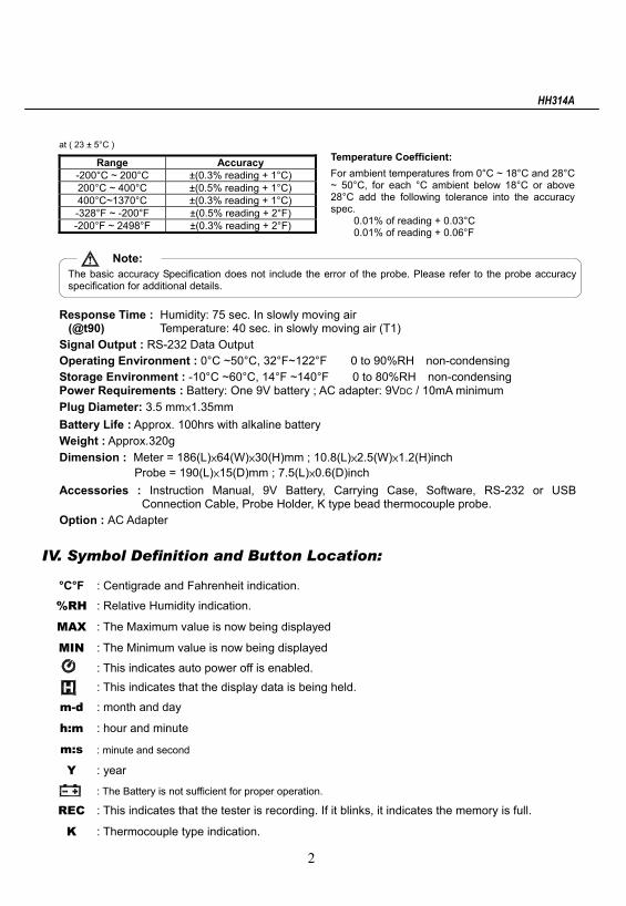
at ( 23 ± 5°C ) Range Accuracy
-200°C ~ 200°C ±(0.3% reading + 1°C) 200°C ~ 400°C ±(0.5% reading + 1°C) 400°C~1370°C ±(0.3% reading + 1°C) -328°F ~ -200°F ±(0.5% reading + 2°F) -200°F ~ 2498°F ±(0.3% reading + 2°F)
Note: The basic accuracy Specification does not include the error of the probe. Please refer to the probe accuracy specification for additional details.
Response Time : Humidity: 75 sec. In slowly moving air
(@t90) Temperature: 40 sec. in slowly moving air (T1) Signal Output : RS-232 Data Output Operating Environment : 0°C ~50°C, 32°F~122°F 0 to 90%RH non-condensing Storage Environment : -10°C ~60°C, 14°F ~140°F 0 to 80%RH non-condensing Power Requirements : Battery: One 9V battery ; AC adapter: 9VDC / 10mA minimum Plug Diameter: 3.5 mm×1.35mm Battery Life : Approx. 100hrs with alkaline battery Weight : Approx.320g Dimension : Meter = 186(L)×64(W)×30(H)mm ; 10.8(L)×2.5(W)×1.2(H)inch
Probe = 190(L)×15(D)mm ; 7.5(L)×0.6(D)inch Accessories : Instruction Manual, 9V Battery, Carrying Case, Software, RS-232 or USB
Connection Cable, Probe Holder, K type bead thermocouple probe. Option : AC Adapter
IV. Symbol Definition and Button Location:
°C°F : Centigrade and Fahrenheit indication.
%RH : Relative Humidity indication.
MAX : The Maximum value is now being displayed
MIN : The Minimum value is now being displayed
: This indicates auto power off is enabled. : This indicates that the display data is being held.
m-d : month and day
h:m : hour and minute
m:s : minute and second
Y : year
: The Battery is not sufficient for proper operation.
REC : This indicates that the tester is recording. If it blinks, it indicates the memory is full.
K : Thermocouple type indication.
Temperature Coefficient: For ambient temperatures from 0°C ~ 18°C and 28°C ~ 50°C, for each °C ambient below 18°C or above 28°C add the following tolerance into the accuracy spec.
0.01% of reading + 0.03°C 0.01% of reading + 0.06°F
HH314A
3
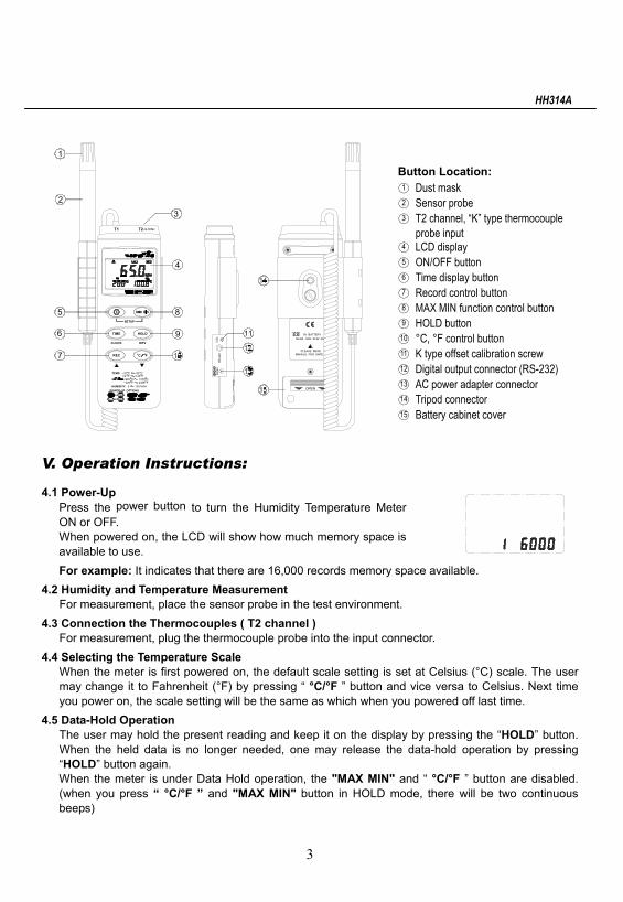
Button Location: ○1 Dust mask ○2 Sensor probe ○3 T2 channel, “K” type thermocouple
probe input ○4 LCD display ○5 ON/OFF button ○6 Time display button ○7 Record control button ○8 MAX MIN function control button ○9 HOLD button ○10 °C, °F control button ○11 K type offset calibration screw ○12 Digital output connector (RS-232) ○13 AC power adapter connector ○14 Tripod connector ○15 Battery cabinet cover
V. Operation Instructions:
4.1 Power-Up Press the power button to turn the Humidity Temperature Meter ON or OFF. When powered on, the LCD will show how much memory space is available to use. For example: It indicates that there are 16,000 records memory space available.
4.2 Humidity and Temperature Measurement For measurement, place the sensor probe in the test environment.
4.3 Connection the Thermocouples ( T2 channel ) For measurement, plug the thermocouple probe into the input connector.
4.4 Selecting the Temperature Scale When the meter is first powered on, the default scale setting is set at Celsius (°C) scale. The user may change it to Fahrenheit (°F) by pressing “ °C/°F ” button and vice versa to Celsius. Next time you power on, the scale setting will be the same as which when you powered off last time.
4.5 Data-Hold Operation The user may hold the present reading and keep it on the display by pressing the “HOLD” button. When the held data is no longer needed, one may release the data-hold operation by pressing “HOLD” button again. When the meter is under Data Hold operation, the "MAX MIN" and “ °C/°F ” button are disabled. (when you press “ °C/°F ” and "MAX MIN" button in HOLD mode, there will be two continuous beeps)
RS
-232
DC
9VC
AL
11
MANUAL FOR SAFE
OPEN
NEDA 1604 6F22 00
PLEASE READ
9V BATTERY
POWER-UP OPTIONS
REC
1370200( ) C CF
HUMIDITY: 0328 2498
%RH100F
TEMP:FC
420
REC
14060
FC
C F
SETUP
CLOCK
TIME
INTV
HOLD
T1 K-TYPE(T2 )
6
7
5
1
9
8
4
3
2
HH314A
4
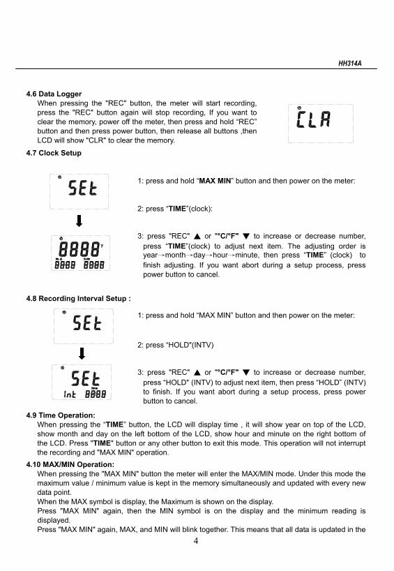
4.6 Data Logger When pressing the "REC" button, the meter will start recording, press the "REC" button again will stop recording, If you want to clear the memory, power off the meter, then press and hold “REC” button and then press power button, then release all buttons ,then LCD will show "CLR" to clear the memory.
4.7 Clock Setup
1: press and hold “MAX MIN” button and then power on the meter: 2: press “TIME”(clock): 3: press "REC" ▲ or "°C/°F" ▼ to increase or decrease number,
press “TIME”(clock) to adjust next item. The adjusting order is year→month→day→hour→minute, then press “TIME” (clock) to finish adjusting. If you want abort during a setup process, press power button to cancel.
4.8 Recording Interval Setup :
1: press and hold “MAX MIN” button and then power on the meter: 2: press “HOLD"(INTV) 3: press "REC" ▲ or "°C/°F" ▼ to increase or decrease number,
press “HOLD" (INTV) to adjust next item, then press “HOLD” (INTV) to finish. If you want abort during a setup process, press power button to cancel.
4.9 Time Operation: When pressing the “TIME” button, the LCD will display time , it will show year on top of the LCD, show month and day on the left bottom of the LCD, show hour and minute on the right bottom of the LCD. Press "TIME" button or any other button to exit this mode. This operation will not interrupt the recording and "MAX MIN" operation.
4.10 MAX/MIN Operation: When pressing the "MAX MIN" button the meter will enter the MAX/MIN mode. Under this mode the maximum value / minimum value is kept in the memory simultaneously and updated with every new data point. When the MAX symbol is display, the Maximum is shown on the display. Press "MAX MIN" again, then the MIN symbol is on the display and the minimum reading is displayed. Press "MAX MIN" again, MAX, and MIN will blink together. This means that all data is updated in the
HH314A
5
TX RX GND
memory and the reading is the present temperature. One may press "MAX MIN" to circulate the display mode among these options. When the meter is under "MAX MIN" operation, “ °C/°F ” button are disabled.(when you press “ °C/°F ” button in "MAX MIN" mode, there will be two continuous beep) To exit the MAX/MIN mode, one may press and hold "MAX MIN" for two seconds.
4.11 Auto Power Off: By default, when the meter is powered on, it is under auto power off mode. The meter will power itself off after 30 minutes if no key operation and no RS232 communication combination at power on can disable auto power off. One may press and hold “HOLD” button and then power on the meter and there will be two successive beeps to indicate that auto power off is disabled and the will not show up.
4.12 Low Battery Condition When the battery voltage is under proper operation requirement, the symbol will show on the LCD and the battery need to be replaced with new one.
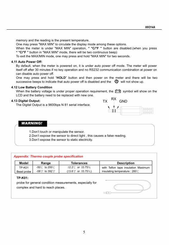
4.13 Digital Output: The Digital Output is a 9600bps N 81 serial interface.
1.Don’t touch or manipulate the sensor. 2.Don’t expose the sensor to direct light , this causes a false reading. 3.Don’t expose the sensor to static electricity.
Appendix: Thermo couple probe specification
Model Range Tolerances Description TP-K01
Bead probe -50℃ to 200℃ -58℉ to 392℉
±2.2℃ or ±0.75% (±3.6℉ or ±0.75%)
with Teflon tape insulation Maximum insulating temperature : 260℃
WARNING!
TP-K01: probe for general condition measurements, especially for complex and hard to reach places.
HH314A
6
VI. Calibration Procedure:
Humidity Calibration:
1. Turn the unit off. Press and hold MAX/MIN, HOLD and REC keys. While these three keys are pressed, turn the power on. Release these keys and all the segments on the LCD will blink.
2. After step one, within 3 seconds, the user have to press °C/°F and TIME key at the same time to enter the calibration mode or the tester will go back to normal operation mode.
3. When the tester get into calibration mode, the humidity reading will blink and “CAL1” will appear on the second display.
4. Insert the humidity probe into the standard humidity cavity of 32.8%RH@25°C. Wait until the system to stabilize for 20 minutes then press MAX/MIN button to create the calibration data. If the unit recognizes the value is out of tolerance, the unit will sound 2 beeps and still remain at "CAL1”mode. If the tester recognizes the value is within tolerance, new calibration data is created and the tester will go into “CAL2” mode, which will be indicated by “CAL2” at 2nd display.
5. Insert the humidity probe into the standard humidity cavity of 75.3%RH@25°C. Wait until the system to stabilize for 20 minutes then press MAX/MIN button to create the calibration data. If the unit recognizes the value is out of tolerance, the unit will sound 2 beeps and still remain at "CAL2”mode. If the tester recognizes the value is within tolerance, new calibration data will be written into the memory and the calibration is done.
Remark: 1. When the user perform the humidity calibration, the environment should be kept at the stable
condition (i.e. Constant temperature and constant humidity in the lab.) to in increase the accuracy.
2. After the probe insert into the standard humidity cavity, the operator should wait at least 20 minutes to let the condition in the cavity to stabilize.
3. During the calibration, if the user press POWER button at any time, the tester will go back to normal operation mode and no calibration data will be changed.
4. During the calibration mode, the user can restore the factory default value by press the HOLD and REC buttons at the same time.
5. Because it takes some time to stabilize the system, we recommend the operator first insert the probe into the 32.8%RH@25°C standard cavity and wait for at least 20 minutes, then power the unit on and start the calibration process.
6. During the calibration, all the displayed reading is calibrated with the old calibration data and the auto power function is disabled. Until the calibration process is done, the tester will enable auto power function again.
7. During the calibration, the temperature is fixed at °F scale and it is not selectable.
T1 Temperature Calibration:
1. Turn the unit off. Press and hold MAX/MIN, HOLD and REC keys. While these three keys are pressed, turn the power on. Release these keys and all the segments on the LCD will blink.
2. After step one, within 3 seconds, the user have to press °C/°F and HOLD key at the same time to enter the calibration mode or the tester will go back to normal operation mode.
3. When the tester get into calibration mode, the temperature reading will blink and “CAL1” will appear on the second display.
HH314A
7
4. Insert the probe into standard chamber of 0°C(32°F) and wait the system to stabilize for 20 minutes. Press MAX/MIN button to create the calibration data. If the tester recognizes the data is within the tolerance, it will go to “CAL2” mode or it will sound 2 beeps and remain at “CAL1” mode.
5. Insert the probe into standard chamber of 40°C(104°F) and wait the system to stabilize for 20 minutes. Press MAX/MIN button to create the calibration data. If the tester recognizes the data is within the tolerance, it will write the calibration data into the memory and leave the calibration mode. If the tester recognizes the calibration data is out of tolerance it will beep 2 times and remain at “CAL2” mode.
Remarks: 1. After the probe is in the calibration cavity, wait at least 20 minutes to stabilize the system. 2. During the calibration, the user can leave the process by pressing the POWER button at any
time and the calibration data will be kept unchanged. 3. During the calibration mode, the user can restore the factory default value by press the HOLD
and REC buttons at the same time. 4. Because it take some time to stabilize the system, we recommend the operator first insert the
probe into the 0°C standard cavity and wait for at least 20 minutes, then power the unit on and start the calibration process.
5. During the calibration, all the displayed reading is calibrated with the old calibration data and the auto power function is disabled. Until the calibration process is done, the tester will enable auto power function again.
6. During the calibration, the temperature scale is fixed at °F and it is not selectable.
VII. Setup HH310-SW—RS232 interface software: The HH310-SW package contains:
1.One setup CD. 2.Custom designed RS232 cable for TestLink SE-310.
System Required: Windows 2000//XP/2003 Server/Vista.
Minimum Hardware Required: 486-100 MHz PC compatible, 16 MB RAM ; At least 5 MB hard disk space available to install TestLink SE-310 program. Recommended display resolution is 800X600.
Install TestLink SE-310: 1.We recommend close all other application before installing TestLink SE-310. 2.Insert the HH310-SW CD-ROM into your CD drive. The TestLink SE-310 installer should start automatically. If it does not, you can start it by running SETUP.EXE from the root drive of the CD-ROM. 3.When installation is complete, it will copy TestLink SE-310.exe(executable file) and help file to your hard disk(default is c:\program files\ TestLink SE-310) 4.For other operation instruction, please refer to the on-line help while executing TestLink SE-310.
HH314A
8
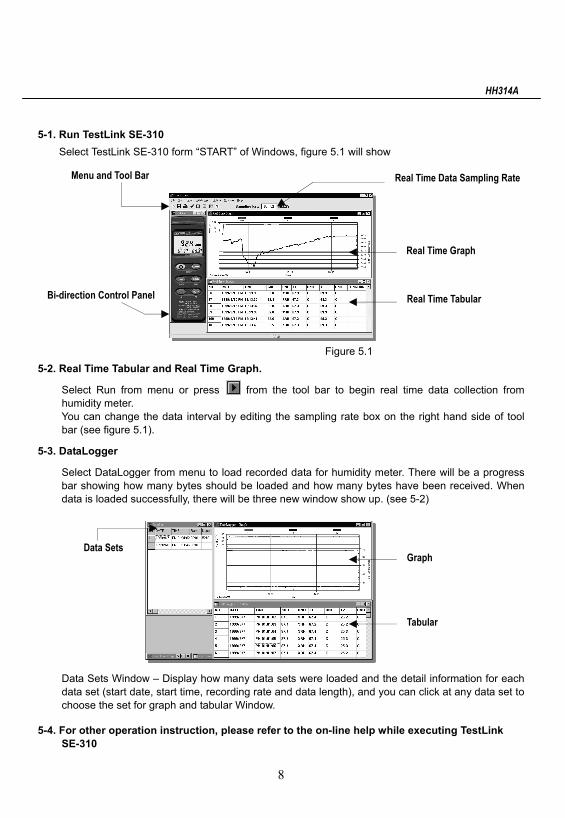
5-1. Run TestLink SE-310 Select TestLink SE-310 form “START” of Windows, figure 5.1 will show
Figure 5.1 5-2. Real Time Tabular and Real Time Graph.
Select Run from menu or press from the tool bar to begin real time data collection from humidity meter. You can change the data interval by editing the sampling rate box on the right hand side of tool bar (see figure 5.1).
5-3. DataLogger
Select DataLogger from menu to load recorded data for humidity meter. There will be a progress bar showing how many bytes should be loaded and how many bytes have been received. When data is loaded successfully, there will be three new window show up. (see 5-2)
Data Sets Window – Display how many data sets were loaded and the detail information for each data set (start date, start time, recording rate and data length), and you can click at any data set to choose the set for graph and tabular Window.
5-4. For other operation instruction, please refer to the on-line help while executing TestLink SE-310
Real Time Graph
Real Time Tabular Bi-direction Control Panel
Menu and Tool Bar Real Time Data Sampling Rate
Data Sets Graph
Tabular

HH309A
7
NOTES:

HH309A
7
NOTES:

HH309A
7
NOTES:
WARRANTY/DISCLAIMEROMEGA ENGINEERING, INC. warrants this unit to be free of defects in materials andworkmanship for a period of 13 months from date of purchase. OMEGA’s Warranty adds anadditional one (1) month grace period to the normal one (1) year product warranty to coverhandling and shipping time. This ensures that OMEGA’s customers receive maximumcoverage on each product.
If the unit malfunctions, it must be returned to the factory for evaluation. OMEGA’s CustomerService Department will issue an Authorized Return (AR) number immediately upon phone orwritten request. Upon examination by OMEGA, if the unit is found to be defective, it will berepaired or replaced at no charge. OMEGA’s WARRANTY does not apply to defects resultingfrom any action of the purchaser, including but not limited to mishandling, improper interfacing,operation outside of design limits, improper repair, or unauthorized modification. This WARRANTY is VOID if the unit shows evidence of having been tampered with or shows evidenceof having been damaged as a result of excessive corrosion; or current, heat, moisture or vibra-tion; improper specification; misapplication; misuse or other operating conditions outside ofOMEGA’s control. Components which wear are not warranted, including but not limited tocontact points, fuses, and triacs.
OMEGA is pleased to offer suggestions on the use of its various products. However, OMEGA neither assumes responsibility for any omissions or errors nor assumes liabilityfor any damages that result from the use of its products in accordance with informationprovided by OMEGA, either verbal or written. OMEGA warrants only that the parts manufactured by it will be as specified and free of defects. OMEGA MAKES NO OTHER WARRANTIES OR REPRESENTATIONS OF ANY KIND WHATSOEVER, EXPRESS ORIMPLIED, EXCEPT THAT OF TITLE, AND ALL IMPLIED WARRANTIES INCLUDING ANYWARRANTY OF MERCHANTABILITY AND FITNESS FOR A PARTICULAR PURPOSE AREHEREBY DISCLAIMED. LIMITATION OF LIABILITY: The remedies of purchaser set forthherein are exclusive, and the total liability of OMEGA with respect to this order, whetherbased on contract, warranty, negligence, indemnification, strict liability or otherwise, shallnot exceed the purchase price of the component upon which liability is based. In no eventshall OMEGA be liable for consequential, incidental or special damages.
CONDITIONS: Equipment sold by OMEGA is not intended to be used, nor shall it be used: (1) asa “Basic Component” under 10 CFR 21 (NRC), used in or with any nuclear installation or activity;or (2) in medical applications or used on humans. Should any Product(s) be used in or with anynuclear installation or activity, medical application, used on humans, or misused in any way,OMEGA assumes no responsibility as set forth in our basic WARRANTY/ DISCLAIMER language,and, additionally, purchaser will indemnify OMEGA and hold OMEGA harmless from any liabilityor damage whatsoever arising out of the use of the Product(s) in such a manner.
RETURN REQUESTS/INQUIRIESDirect all warranty and repair requests/inquiries to the OMEGA Customer Service Department.BEFORE RETURNING ANY PRODUCT(S) TO OMEGA, PURCHASER MUST OBTAIN ANAUTHORIZED RETURN (AR) NUMBER FROM OMEGA’S CUSTOMER SERVICE DEPARTMENT(IN ORDER TO AVOID PROCESSING DELAYS). The assigned AR number should then bemarked on the outside of the return package and on any correspondence.The purchaser is responsible for shipping charges, freight, insurance and proper packaging toprevent breakage in transit.
FOR WARRANTY RETURNS, please havethe following information available BEFORE contacting OMEGA:1. Purchase Order number under which
the product was PURCHASED,2. Model and serial number of the product
under warranty, and3. Repair instructions and/or specific
problems relative to the product.
FOR NON-WARRANTY REPAIRS, consultOMEGA for current repair charges. Have thefollowing information available BEFORE contacting OMEGA:1. Purchase Order number to cover the COST
of the repair,2. Model and serial number of the product, and3. Repair instructions and/or specific problems
relative to the product.
OMEGA’s policy is to make running changes, not model changes, whenever an improvement is possible. This affords our customers the latest in technology and engineering.OMEGA is a registered trademark of OMEGA ENGINEERING, INC.© Copyright 2008 OMEGA ENGINEERING, INC. All rights reserved. This document may not be copied, photocopied,reproduced, translated, or reduced to any electronic medium or machine-readable form, in whole or in part, withoutthe prior written consent of OMEGA ENGINEERING, INC.

Where Do I Find Everything I Need forProcess Measurement and Control?
OMEGA…Of Course!Shop online at omega.com sm
TEMPERATURE�� Thermocouple, RTD & Thermistor Probes, Connectors, Panels & Assemblies�� Wire: Thermocouple, RTD & Thermistor�� Calibrators & Ice Point References�� Recorders, Controllers & Process Monitors�� Infrared Pyrometers
PRESSURE, STRAIN AND FORCE�� Transducers & Strain Gages�� Load Cells & Pressure Gages�� Displacement Transducers�� Instrumentation & Accessories
FLOW/LEVEL�� Rotameters, Gas Mass Flowmeters & Flow Computers�� Air Velocity Indicators�� Turbine/Paddlewheel Systems�� Totalizers & Batch Controllers
pH/CONDUCTIVITY�� pH Electrodes, Testers & Accessories�� Benchtop/Laboratory Meters�� Controllers, Calibrators, Simulators & Pumps�� Industrial pH & Conductivity Equipment
DATA ACQUISITION�� Data Acquisition & Engineering Software�� Communications-Based Acquisition Systems�� Plug-in Cards for Apple, IBM & Compatibles�� Datalogging Systems�� Recorders, Printers & Plotters
HEATERS�� Heating Cable�� Cartridge & Strip Heaters�� Immersion & Band Heaters�� Flexible Heaters�� Laboratory Heaters
ENVIRONMENTALMONITORING AND CONTROL�� Metering & Control Instrumentation�� Refractometers�� Pumps & Tubing�� Air, Soil & Water Monitors�� Industrial Water & Wastewater Treatment�� pH, Conductivity & Dissolved Oxygen Instruments M3551A/0508