hpe integrity rx2800 i2 server user service guideh20628. integrity rx2800 i2 server user service...
TRANSCRIPT

HPE Integrity rx2800 i2 Server UserService Guide
Part Number: AH395-9013JPublished: September 2017Edition: 13
AbstractThis document contains specific information that is intended for users of this Hewlett PackardEnterprise product.
Contents
Overview................................................................................................ 11Server subsystems......................................................................................................................12
Internal components.........................................................................................................13I/O subsystem.................................................................................................................. 15RAID support....................................................................................................................15
Controls and ports.......................................................................................................................16Front panel controls and ports......................................................................................... 17
Storage and media devices...................................................................................17Rear panel controls and ports.......................................................................................... 18
Site preparation.....................................................................................20Server dimensions and weight....................................................................................................20Grounding................................................................................................................................... 20Server electrical specifications....................................................................................................20
System power specifications............................................................................................20Power consumption and cooling...................................................................................... 21
Server physical and environmental specifications...................................................................... 22Unpacking and inspecting the server............................................................................... 23
Verifying site preparation.......................................................................................23Inspecting the shipping containers for damage.....................................................23Unpacking the server.............................................................................................23Verifying the inventory........................................................................................... 23Returning damaged equipment............................................................................. 24Unloading the server with a lifter........................................................................... 24
Installing the server.............................................................................. 25Safety information....................................................................................................................... 25Preventing electrostatic discharge.............................................................................................. 25Installation sequence and checklist............................................................................................ 26Installing the server into a rack or pedestal................................................................................ 26
Rack installation............................................................................................................... 26Hewlett Packard Enterprise rack........................................................................... 26Non-Hewlett Packard Enterprise rack................................................................... 26
Pedestal kit installation.....................................................................................................27Remove the rails from the server.......................................................................... 27Attaching the pedestal kit top and bottom............................................................. 27Attaching the bezel cover...................................................................................... 30Attaching the pedestal kit side pieces................................................................... 30Attaching the pedestal feet....................................................................................32
Connecting server cables........................................................................................................... 33AC input power.................................................................................................................33
Power states..........................................................................................................33Applying standby power to the server................................................................... 34
Connecting to the LAN..................................................................................................... 34Setting up the system................................................................................................................. 35
Setup checklist................................................................................................................. 35Accessing UEFI or the OS from iLO MP.....................................................................................35
UEFI Front Page.............................................................................................................. 37
2 Contents

Saving UEFI configuration settings....................................................................... 39Booting and installing the operating system.....................................................................39Operating system is loaded onto the server.....................................................................39Operating system is not loaded onto the server...............................................................39OS login prompt............................................................................................................... 40
Powering on and powering off the server....................................................................................40Power states.....................................................................................................................40Powering on the server.................................................................................................... 40
Powering on the server using the iLO 3 MP..........................................................40Powering on the server manually.......................................................................... 41
Powering off the server.................................................................................................... 41Powering off the server using the iLO 3 MP..........................................................41Powering off the server manually.......................................................................... 41
Installing the latest firmware using Smart Update Manager....................................................... 42Troubleshooting installation issues............................................................................................. 42
Operating system procedures............................................................. 43Operating systems supported on the server............................................................................... 43Installing the operating system onto the server.......................................................................... 43
Installing the operating system from the DVD drive or tape drive.................................... 43Installing the operating system using HP Ignite-UX......................................................... 45Installing HPE OpenVMS with Infoserver Utility...............................................................45Installing the operating system with Virtual Media........................................................... 45
Configuring system boot options.................................................................................................45Booting and shutting down HP-UX............................................................................................. 46
Adding HP-UX to the boot options list..............................................................................46HP-UX standard boot....................................................................................................... 47
Booting HP-UX from the UEFI Boot Manager....................................................... 48Booting HP-UX from the UEFI Shell......................................................................48
Booting HP-UX in single-user mode................................................................................ 49Booting HP-UX in LVM-maintenance mode..................................................................... 49Shutting down HP-UX...................................................................................................... 49
Booting and shutting down OpenVMS........................................................................................ 49Adding OpenVMS to the Boot Options list....................................................................... 50Booting OpenVMS........................................................................................................... 51
Booting OpenVMS from the UEFI Boot Manager..................................................51Booting OpenVMS from the UEFI Shell................................................................ 51
Shutting down OpenVMS.................................................................................................52Booting and shutting down Microsoft Windows operating systems............................................ 52
Adding Microsoft Windows operating systems to the boot options list.............................53Booting the Microsoft Windows operating system........................................................... 54Shutting down Microsoft Windows................................................................................... 55
Shutting down Windows operating systems from the command line.................... 56
Optional components........................................................................... 57Installing a hot-pluggable SAS hard drive...................................................................................57Installing a hot-swappable power supply.................................................................................... 58Removing the access panel........................................................................................................60Removing the PCI riser cage...................................................................................................... 60Removing expansion slot covers................................................................................................ 61Installing expansion boards........................................................................................................ 62
Installing a half-length expansion board...........................................................................63Installing a full-length expansion board............................................................................63
Installing DIMMs..........................................................................................................................64
Contents 3

Memory configurations.....................................................................................................64Supported DIMM sizes.......................................................................................... 64Memory expansion board locations and slot IDs...................................................65Memory loading rules and guidelines....................................................................66
Installing DIMMs...............................................................................................................67Installing a processor.................................................................................................................. 68
Processor load order........................................................................................................69Installing a processor and heat sink module.................................................................... 69
HPE Trusted Platform Module (TPM)......................................................................................... 75Installing a Trusted Platform Module (TPM) and TPM security rivet................................ 76
Verifying installed components in the server...............................................................................79Completing installation................................................................................................................81
Troubleshooting.................................................................................... 82How to contact Hewlett Packard Enterprise................................................................................82Methodology............................................................................................................................... 82
General troubleshooting methodology............................................................................. 82Recommended troubleshooting methodology .................................................................83Basic and advanced troubleshooting tables.....................................................................84
Troubleshooting tools..................................................................................................................91LEDs ................................................................................................................................91
Front panel LEDs...................................................................................................92Rear panel LEDs................................................................................................. 100
Diagnostics.....................................................................................................................101Online diagnostics and exercisers................................................................................. 102
Online support tool availability.............................................................................102Online support tools list....................................................................................... 102
Offline support tools list..................................................................................................103Fault management overview.......................................................................................... 104HP-UX fault management.............................................................................................. 104
WBEM indication providers................................................................................. 105OpenVMS fault management and monitoring................................................................ 105
Errors and reading error logs.................................................................................................... 105Event log definitions....................................................................................................... 105Using event logs.............................................................................................................106iLO 3 MP event logs.......................................................................................................106System event log review................................................................................................ 107
Supported configurations.......................................................................................................... 107Server block diagram..................................................................................................... 108System build-up troubleshooting procedure...................................................................108
Installation troubleshooting........................................................................................................110Installation troubleshooting methodology....................................................................... 110Installation troubleshooting using the server power button.............................................111Server does not power on...............................................................................................111UEFI menu is not available.............................................................................................112Operating system does not boot.....................................................................................112Operating system boots with issues...............................................................................112Intermittent server issues............................................................................................... 112SATA DVD+RW drive issues.......................................................................................... 113SAS disk drive issues.....................................................................................................113Console issues............................................................................................................... 113
Troubleshooting the processor and memory.............................................................................114Troubleshooting the server processor............................................................................ 114
Processor load order........................................................................................... 114Processor module behaviors............................................................................... 114
4 Contents

Customer messaging policy.................................................................................114Troubleshooting the server memory...............................................................................117
Memory DIMM load order....................................................................................117Memory subsystem behaviors.............................................................................117Customer messaging policy.................................................................................118
Troubleshooting the power subsystem......................................................................................118Power subsystem behavior............................................................................................ 119Power LED button.......................................................................................................... 119
Troubleshooting the cooling subsystem....................................................................................120Cooling subsystem behavior.......................................................................................... 120
Troubleshooting the I/O.............................................................................................................121I/O subsystem behaviors................................................................................................121Customer messaging policy........................................................................................... 121
Troubleshooting the iLO 3 MP subsystem................................................................................ 123iLO 3 MP LAN LED on the rear panel............................................................................ 123
Troubleshooting the I/O subsystem ......................................................................................... 124Verifying SAS hard drive operation................................................................................ 124System LAN LEDs..........................................................................................................124
Troubleshooting the boot process.............................................................................................125Troubleshooting the firmware....................................................................................................126
Identifying and troubleshooting firmware issues............................................................ 126Updating firmware.......................................................................................................... 127
Troubleshooting the system console.........................................................................................127Troubleshooting the server environment ..................................................................................128
Removal and replacement procedures............................................. 129Server components list............................................................................................................. 129Required tools...........................................................................................................................132Safety considerations................................................................................................................132
Server warnings and cautions........................................................................................132Preparation procedures............................................................................................................ 133
Extending the server from the rack................................................................................ 134Accessing internal components for a pedestal-mounted server.................................... 135Powering off the server.................................................................................................. 138Removing the server from the rack................................................................................ 139Removing the server from the pedestal kit.....................................................................139
Required tools..................................................................................................... 139Power off the server and remove cables.............................................................139
Removing the pedestal kit..............................................................................................139Access the product rear panel....................................................................................... 143
Cable management arm with left-hand swing..................................................... 143Cable management arm with right-hand swing................................................... 144
Removing and replacing a power supply blank........................................................................ 144Removing and replacing a hot-plug SAS hard drive................................................................. 145Removing and replacing a power supply blank........................................................................ 146Removing and replacing a hot-swap power supply.................................................................. 146Removing and replacing the access panel............................................................................... 148Removing and replacing the optical drive filler......................................................................... 148Removing and replacing the optical drive................................................................................. 148Removing and replacing a hot-swap fan...................................................................................150Removing and replacing the power supply backplane..............................................................151Removing and replacing the hard drive backplane...................................................................152Removing and replacing the PCI riser cage............................................................................. 153Removing and replacing expansion slot covers........................................................................153Removing and replacing expansion boards..............................................................................153
Contents 5

Removing and replacing a half-length expansion board................................................ 154Removing and replacing a full-length expansion board................................................. 155
Removing and replacing the cache module..............................................................................156Removing and replacing the super capacitor pack................................................................... 157Removing and replacing the processor baffle...........................................................................159Removing and replacing a processor and heat sink module.................................................... 160Removing and replacing DIMMs...............................................................................................164Removing and replacing the PDH battery (system battery)......................................................166Removing and replacing the SID.............................................................................................. 167Removing and replacing the intrusion switch cable.................................................................. 170Removing and replacing the system board...............................................................................171
Support and other resources.............................................................177Accessing Hewlett Packard Enterprise Support....................................................................... 177Accessing updates....................................................................................................................177Websites................................................................................................................................... 178Customer self repair..................................................................................................................178Documentation feedback.......................................................................................................... 178
Standard terms, abbreviations and acronyms................................. 179
Utilities................................................................................................. 181SAS disk setup..........................................................................................................................181
Using the saupdate command .................................................................................... 181Get mode.............................................................................................................181Set mode............................................................................................................. 182
Updating the firmware using saupdate ....................................................................... 183Determining the Driver ID and CTRL ID.........................................................................184Using the ORCA menu-driven interface.........................................................................184
Creating a logical drive........................................................................................185Deleting a logical drive........................................................................................ 185Adding a RAID Advanced Pack license key........................................................185Viewing RAID advanced pack license keys.........................................................187
UEFI..........................................................................................................................................187UEFI shell and HPE POSSE commands....................................................................... 188
Drive paths in UEFI...................................................................................................................191Using the boot maintenance manager...................................................................................... 192
Boot options................................................................................................................... 193Add boot option................................................................................................... 194Delete boot option............................................................................................... 195Change boot order.............................................................................................. 196
Driver options................................................................................................................. 197Add driver option................................................................................................. 198Delete driver option............................................................................................. 199Change driver order............................................................................................ 199
Console options............................................................................................................. 200Boot from file.................................................................................................................. 200Set boot next value........................................................................................................ 200Set time out value.......................................................................................................... 201Reset system..................................................................................................................201
iLO MP...................................................................................................................................... 202
6 Contents

Warranty and regulatory information................................................203Warranty information.................................................................................................................203Regulatory information..............................................................................................................203
Belarus Kazakhstan Russia marking............................................................................. 203Turkey RoHS material content declaration.....................................................................204Ukraine RoHS material content declaration................................................................... 204
Contents 7

NoticesThe information contained herein is subject to change without notice. The only warranties for HewlettPackard Enterprise products and services are set forth in the express warranty statements accompanyingsuch products and services. Nothing herein should be construed as constituting an additional warranty.Hewlett Packard Enterprise shall not be liable for technical or editorial errors or omissions containedherein.
Confidential computer software. Valid license from Hewlett Packard Enterprise required for possession,use, or copying. Consistent with FAR 12.211 and 12.212, Commercial Computer Software, ComputerSoftware Documentation, and Technical Data for Commercial Items are licensed to the U.S. Governmentunder vendor's standard commercial license.
Links to third-party websites take you outside the Hewlett Packard Enterprise website. Hewlett PackardEnterprise has no control over and is not responsible for information outside the Hewlett PackardEnterprise website.
AcknowledgmentsIntel® and Itanium® are trademarks of Intel Corporation in the United States and other countries.
Microsoft®, Windows®, and Windows Server® are trademarks of the Microsoft group of companies.
Revision historyThe publishing history table identifies the publication dates of this manual. Updates are made to thispublication on an unscheduled, as needed, basis. The updates will consist of a complete replacementmanual and pertinent online or CD documentation.
The document printing date and part number indicate the current edition. The printing date changes whena new edition is printed. Minor changes might be made at reprint without changing the printing date. Thedocument part number changes when extensive changes are made. The latest version of this documentcan be found online at:
http://www.hpe.com/info/Integrity Servers-docs
Documentmanufacturingpart number
Operating systemssupported
Supported productversions
Edition number Publication date
AH395-9004A• HP-UX
• Microsoft®Windows®
rx2800 i2 First November 2010
AH395-9013A• HP-UX
• OpenVMS
• MicrosoftWindows
rx2800 i2 Second February 2011
Table Continued

Documentmanufacturingpart number
Operating systemssupported
Supported productversions
Edition number Publication date
AH395-9013A_ed3 • HP-UX
• OpenVMS
• MicrosoftWindows
rx2800 i2 Third March 2011
AH395-9013B• HP-UX
• OpenVMS
• MicrosoftWindows
rx2800 i2 Fourth May 2011
AH395-9013C• HP-UX
• OpenVMS
• MicrosoftWindows
rx2800 i2 Fifth August 2011
AH395-9013D• HP-UX
• OpenVMS
• MicrosoftWindows
rx2800 i2 Sixth November 2011
AH395-9013E• HP-UX
• OpenVMS
• MicrosoftWindows
rx2800 i2 Seventh February 2012
AH395-9013F• HP-UX
• OpenVMS
• MicrosoftWindows
rx2800 i2 Eighth August 2012
Table Continued

Documentmanufacturingpart number
Operating systemssupported
Supported productversions
Edition number Publication date
AH395-9013G• HP-UX
• OpenVMS
• MicrosoftWindows
rx2800 i2 Ninth February 2013
AH395-9013J• HP-UX
• OpenVMS
• MicrosoftWindows
rx2800 i2 Tenth September 2017
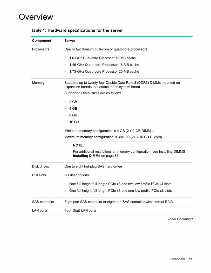
OverviewTable 1: Hardware specifications for the server
Component Server
Processors One or two Itanium dual-core or quad-core processors:
• 1.6-GHz Dual-core Processor 10-MB cache
• 1.46-GHz Quad-core Processor 16-MB cache
• 1.73-GHz Quad-core Processor 20-MB cache
Memory Supports up to twenty-four Double Data Rate 3 (DDR3) DIMMs mounted onexpansion boards that attach to the system board.
Supported DIMM sizes are as follows:
• 2 GB
• 4 GB
• 8 GB
• 16 GB
Minimum memory configuration is 4 GB (2 x 2-GB DIMMs).
Maximum memory configuration is 384 GB (24 x 16 GB DIMMs).
NOTE:
For additional restrictions on memory configuration, see Installing DIMMS Installing DIMMs on page 67.
Disk drives One to eight hot-plug SAS hard drives
PCI slots I/O riser options:
• One full height full length PCIe x8 and two low profile PCIe x4 slots
• One full height full length PCIe x8 and one low profile PCIe x8 slots
SAS controller Eight port SAS controller or eight port SAS controller with internal RAID
LAN ports Four GigE LAN ports
Table Continued
Overview 11

Component Server
Management ports One serial port, four USB 2.0 ports, one 1G/100/10 LAN port, and two VGA ports
NOTE:
The serial port is intended primarily for use as a serial console port. It can beconfigured through iLO 3 for use with other serial devices (subject to OS anddevice limitations and dependencies). The serial port reverts to consolemode settings if the server is disconnected from AC power or if the iLO isreset by the iLO Physical Presence button.
Optical drive One SATA DVD+RW drive
Power supply One (AH395A) or two power supplies (AH396A) are standard. Supplies are dualrange input: 100-120VAC & 200-240VAC capable. 1+1 redundancy is possible withthe second supply.
IMPORTANT:
100-120 VAC input limits configuration and redundancy options. For details,see Removing and replacing a hot-swap power supply on page 146.
Server subsystems
12 Server subsystems

Internal components
Figure 1: Internal components
• Fans
• Processors
• DIMM expansion boards
Internal components 13
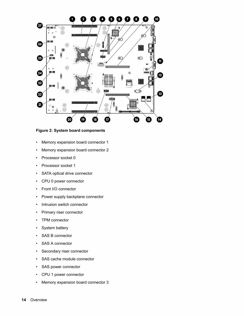
Figure 2: System board components
• Memory expansion board connector 1
• Memory expansion board connector 2
• Processor socket 0
• Processor socket 1
• SATA optical drive connector
• CPU 0 power connector
• Front I/O connector
• Power supply backplane connector
• Intrusion switch connector
• Primary riser connector
• TPM connector
• System battery
• SAS B connector
• SAS A connector
• Secondary riser connector
• SAS cache module connector
• SAS power connector
• CPU 1 power connector
• Memory expansion board connector 3
14 Overview

• Memory expansion board connector 4
• Fan 6 connector
• Fan 5 connector
• Fan 4 connector
• Fan 3 connector
• Internal USB connector
• Fan 2 connector
• Fan 1 connector
Figure 3: Internal USB location
I/O subsystemThe I/O subsystem consists of the core I/O and two optional I/O riser boards. Wake-on-LAN is notenabled on any PCIe Public slots. The server does not support PCI Hot Plug (PHP).
The standard I/O Riser supports one full-height, full-length PCIe x8 and two full-height, half-length PCIex4 add-in cards. The second riser option supports one full-height, full-length PCIe x8, and one full-height,half-length PCIe x8 add-in cards.
NOTE:
All PCIe x8 slots are electrically connected as x8 slots but are physically loaded with x16connectors.
The secondary I/O riser position can either be a riser that supports one full-height, full-length PCIe x8 andtwo low-profile PCIe x4 add-in cards or a riser that supports one full-height, full-length PCIe x8 and onelow profile PCIe x8.
RAID supportThe following levels of RAID support are offered:
• Zero memory
I/O subsystem 15
◦ RAID 0, 1, 10
◦ Maximum 8 drives, 2 logical volumes
◦ No cache or super capacitor needed. Performance improved with cache.
NOTE:
To use all 8 disks with the zero memory option, the following RAID configurations aresupported:
– RAID 0: 1 or 2 LUNs striped with up to 8 disks
– RAID 10: 1 or 2 LUNs striped and mirrored with even number of up to 8 disks
– RAID 1: 1 LUN using 2 mirrored disks, and one additional LUN in RAID 0 or 10
Example configurations of eight disks with zero memory
– LUN 1: RAID 1 bays 1 and 2
– LUN 2: RAID 0 bays 3, 4, 5, 6, and 7
– Hot Spare: bay 8
– LUN 1: RAID 10 bays 1, 2, 3, and 4
– LUN 2: RAID 10 bays 5, 6, 7, and 8
– LUN 1: RAID 0 bays 1, 2, and 3
– LUN 2: RAID 10 bays 5, 6, 7, and 8
– Hot Spare: bay 4
• Full feature
◦ RAID 0, 10, 5
◦ Cache needed and installing it automatically enables the full feature firmware stack. Supercapacitor is optional.
• Advanced pack
◦ RAID 6, 50, 60
◦ Cache needed. Advanced Pack license must be entered to enable. Super capacitor is required.
To enable Advanced Pack licensing, see Adding a RAID Advanced Pack license key on page 185.
Controls and ports
16 Controls and ports

Front panel controls and ports
Figure 4: Front panel components
1. Quick release levers
2. iLO 3 information pull tab
3. SID
4. Optical drive bay
5. Hard drive bays
6. USB connectors
7. Video connector
Storage and media devicesThe server supports up to eight hot-plug SAS HDDs, and one optical (SATA DVD+RW) drive, with LEDsthat indicate activity and device statuses.
Figure 5: SAS device numbers
Front panel controls and ports 17

Rear panel controls and portsThe server rear panel includes communication ports, I/O ports, USB ports, AC power connectors, and thelocator LED and button. LEDs located on the rear panel of the server signal the operational status of therear panel components.
Figure 6: Rear panel components
1. PCI 5
2. PCI 6
3. PCI 4
4. PCI 2
5. PCI 3
6. PCI 1
7. Power supply 2
8. Power supply 2 LED
9. Power supply 2 power connector
10. Power supply 1
11. Power supply 1 LED
12. Power supply 1 power connector
13. UID LED button
14. USB connectors (2)
15. Video connector
16. NIC 1 connector
17. NIC 2 connector
18. iLO 3 physical presence pinhole button
19. Serial connector
20. iLO 3 connector
18 Rear panel controls and ports

21. NIC 3 connector
22. NIC 4 connector
23. NIC link LED
24. NIC activity LED
Overview 19
Site preparationFor information on general computer room site preparation, see the HPE Generalized Site PreparationGuide on the Hewlett Packard Enterprise website:
http://www.hpe.com/info/Integrity_Servers-docs
IMPORTANT:
To avoid hardware damage, allow the thermal mass of the product to equalize to the temperatureand humidity of the installation facility after removing the shipping materials. A minimum of one hourper 10° C (50° F) of temperature difference between the shipping facility and installation facility isrequired.
Server dimensions and weightTable 2: Rack or pedestal-mounted server dimensions
Dimensions and weight Value
Data center server dimensions
Depth 69.2 cm (27.25 in)
Width 48.3 cm (19 in)
Height 8.9 cm (3.5 in)
Weight Maximum configuration – 30 kg (66 lb)
Rack unit 2U
GroundingThe site building must provide a safety ground/protective earth for each AC service entrance to allcabinets.
Install a PE conductor that is identical in size, insulation material, and thickness to the branch-circuitsupply conductors. The PE conductor must be green with yellow stripes. The earthing conductor is to beconnected from the unit to the building installation earth or, if supplied by a separately derived system, atthe supply transformer or motor-generator set grounding point.
Server electrical specifications
System power specificationsAvailable power (output) is the maximum DC power that the power supply can supply to the system.
Maximum input power is what the power supply requires from the AC line to deliver that maximum DCoutput (given worst case efficiency and maximum loading).
Maximum input current is the worst case/highest current given the lowest input voltage and the maximuminput power.
20 Site preparation

Table 3: System power specifications
Parameter
Input voltage 100 V AC 110 - 120 V AC 200 - 240 V AC
Input current (maximum) 9.3 A 9.5 A 6.6 A
Input frequency 47 to 63 Hz 47 to 53 Hz 57 to 63 Hz
Power supply maximum output power 800 W (MAX)
+12V /66.7A MAX
+12VSB /2.5AMAX
900 W (MAX)
+12V /75A MAX
+12VSB /2.5AMAX
1200 W (MAX)
+12V /100A MAX
+12VSB /2.5AMAX
If an overload triggers the power supply overload protection, the system is immediately powered off. Toreset the power supply unit:
Procedure
1. Disconnect the power cord.
2. Determine what caused the overload by contacting a Hewlett Packard Enterprise supportrepresentative.
3. Reconnect the power cord.
4. Reboot the system.
NOTE:
If an overload occurs twice, an undetected short circuit exists.
When you use the front panel power button to turn off the server, power consumption falls below the lowpower consumption, but does not reach zero. To reach zero power consumption in "off" mode, eitherunplug the server or use a power block with a switch.
Power consumption and coolingThe power consumptions listed in Standard configuration power consumption are valid for a standardconfiguration as shipped.
All information in this section is based on primary power consumptions with one power supply installed.
Table 4: Standard configuration power consumption
Standard configuration Power consumption
One 1.46 GHz quad-core processor, 4 GBmemory, one 1200 W power supply, and one SASdisk drive
360 W (maximum) 1228 Btu/h (maximum)
Power consumption and cooling 21

Table 5: Additional component power consumption
Additional component Power consumption
Processor 130 W 443.6 Btu/h
SAS disk drive (with I/O access) 23 W 78.4 Btu/h
SAS disk (idle) 16 W 54.5 Btu/h
PCIe card 10 to 25 W 34.12 Btu/h to 85.30 Btu/h
Server physical and environmental specificationsOperating temperature and humidity ranges might vary, depending on the installed mass storage devices.High humidity levels can cause improper disk operation. Low humidity levels can aggravate staticelectricity issues and cause excessive wear of the disk surface.
NOTE:
De-rate maximum dry bulb temperature 1°/300 m (1000 ft) above 900 m (3000 ft).
Table 6: Environmental specifications (system processing unit with hard disk)
Parameter Value
Data Center Server Office Friendly Server
Operating temperature (up to 1524 m/5000 ft) +5° C to +35° C (+41° F to +95° F)
Non-operating temperature - 40° C to +70° C (40° F to 158° F)
Over-temperature shutdown +38° C (+100° F)
Operating humidity 15% to 80% RH noncondensing
Non-operating humidity 8% to 90% RH at 65° C noncondensing
Acoustic Noise Emission (ISO 9296)
Sound PowerLevel
Maximum configuration (diskactive)
LwAd = 7.0 B LwAd = 6.0 B
Sound Pressure Level LpAm = 52.7 dB LpAm = 42.4 dB
Altitude
Operating altitude 0 to 3000 m (10,000 ft) maximum
Non-operating altitude 0 to 4,600 m (15,000 ft) maximum
22 Server physical and environmental specifications

Unpacking and inspecting the serverThis section describes pre installation procedures. Ensure that you have adequately prepared yourenvironment for installing the new server, received the components that you ordered, and verified that theserver and the containers are in good condition after shipment.
Verifying site preparation
• Gather LAN information. The MAC addresses for the iLO 3 MP LAN and the system LAN are locatedon the iLO Network Information Tag.
• Establish a method to connect to the server console.
• Verify electrical requirements. Ensure that grounding specifications and power requirements are met.
• Validate server physical space requirements.
• Confirm environmental requirements.
For server-specific information on electrical, physical space, and environmental requirements, see the siteprep guide. For general site preparation information, see the HPE Generalized Site Preparation Guideon the Hewlett Packard Enterprise website.
Inspecting the shipping containers for damageUnder normal shipping conditions, Hewlett Packard Enterprise shipping containers protect the contents.After the equipment arrives, carefully inspect each carton for signs of shipping damage. Shipping damageconstitutes moderate to severe damage, such as punctures in the corrugated carton, crushed boxes, orlarge dents. Normal wear or slight damage to the carton is not considered shipping damage. If you findshipping damage to the carton, immediately contact your Hewlett Packard Enterprise customer servicerepresentative.
Unpacking the server
Procedure
1. Follow the instructions printed on the outside top flap of the carton to remove the banding and theouter carton from the server pallet.
2. Remove all inner accessory cartons and the top foam cushions, leaving only the server.
IMPORTANT:
Inspect each carton for shipping damage as you unpack the server.
Verifying the inventoryThe sales order packing slip lists all the equipment shipped from Hewlett Packard Enterprise. Use thispacking slip to verify that all equipment has arrived.
NOTE:
To identify each item by part number, see the sales order packing slip.
Unpacking and inspecting the server 23

Returning damaged equipmentIf the equipment is damaged, immediately contact your Hewlett Packard Enterprise customer servicerepresentative. The service representative initiates appropriate action through the transport carrier or thefactory and assists you in returning the equipment.
Unloading the server with a lifter
WARNING:
Use caution when using a lifter. Because of the weight of the server, to avoid injury, you must centerthe server on the lifter forks before lifting it off the pallet.
NOTE:
Hewlett Packard Enterprise recommends that you follow your local guidelines when liftingequipment.
Procedure
1. Unpack the server.
2. Unroll the bottom corrugated tray corresponding to the side on which the lifter is to be placed, and thenslide the server as close to that edge of the pallet as possible.
3. Break off any foam packaging that can prevent the lifter from being fully inserted under the server. Donot remove the foam packaging from the corners of the server. This foam is required to elevate theserver and to enable the forks of the lifter to be placed under the server.
4. Insert the lifter forks under the server.
5. Carefully roll the lifter forward until it is fully positioned against the side of the server.
6. Slowly raise the server off the pallet until it clears the pallet cushions.
7. Carefully roll the lifter and server away from the pallet. Do not raise the server any higher thannecessary when moving it over to the rack.
24 Returning damaged equipment

Installing the server
Safety informationFollow the instructions carefully to prevent injury and equipment damage when performing removal andreplacement procedures. Voltage might be present within the server. Many assemblies are sensitive todamage by ESD.
Follow the safety considerations listed to ensure safe handling of components, to prevent injury, and toprevent damage to the server:
• If installing a hot-swappable or hot-pluggable component when power is applied (fans are running),reinstall the server cover immediately to prevent overheating.
If installing a hot-pluggable component, complete the required software intervention prior to removingthe component.
• If installing an assembly that is neither hot-swappable nor hot-pluggable, disconnect the power cablefrom the external server power receptacle before starting the installation.
WARNING:
Ensure that the system is powered off and all power sources are disconnected from the serverbefore removing or installing server hardware (unless you are removing or installing a hot-swappable or hot-pluggable component). Voltage is present at various locations within the serverwhenever an AC power source is connected. This voltage is present even when the main powerswitch is off. Failure to observe this warning might result in personal injury or equipmentdamage.
• Do not wear loose clothing that might snag or catch on the server or on other components.
• Do not wear clothing subject to static charge buildup, such as wool or synthetic materials
• If installing an internal assembly, wear an antistatic wrist strap and use a grounding mat, such as thoseincluded in the Electrically Conductive Field Service Grounding Kit.
• Handle accessory boards and components by the edges only. Do not touch any metal edgeconnectors or any electrical components on accessory boards.
Preventing electrostatic dischargeTo prevent damaging the system, be aware of the precautions you need to follow when setting up thesystem or handling parts. A discharge of static electricity from a finger or other conductor might damagesystem boards or other static-sensitive devices. This type of damage might reduce the life expectancy ofthe device.
To prevent electrostatic damage:
• Avoid hand contact by transporting and storing products in static-safe containers.
• Keep electrostatic-sensitive parts in their containers until they arrive at static-free workstations.
• Place parts on a grounded surface before removing them from their containers.
Installing the server 25

• Avoid touching pins, leads, or circuitry.
• Always be properly grounded when touching a static-sensitive component or assembly.
Installation sequence and checklistStep Description Completed
1 Perform site preparation (see Site preparation on page 20).
2 Install the server into a rack or pedestal.
3 Connect cables to the server.
a. Connect the AC input power cable.
b. Connect LAN core I/O cable.
c. Connect the iLO 3 MP LAN cable.
4 Connect and set up the console for access.
5 Power on the server.
6 From iLO MP, access UEFI.
7 Boot the operating system.
8 Using Smart Update Manager, download the latest firmware.
Installing the server into a rack or pedestal
Rack installation
Hewlett Packard Enterprise rackHewlett Packard Enterprise servers that are installed into racks are shipped with equipment-mountingslides. The HPE 2U Quick Deploy Rail System Installation Instructions for HPE Products ships with eachset of slides. Follow the steps in this installation guide to determine where and how to install the serverinto the rack.
For more information on rack deployment, stabilization and transportation, see the 10000 Series G2 RackBest Practices Guide.
http://www.hpe.com/info/rackandpower
Non-Hewlett Packard Enterprise rackFor information on installing a HPE Integrity rx2800 i2 server in a third party rack, see the QuickSpecslocated on the rx2800 i2 server product page.
http://www.hpe.com
26 Installation sequence and checklist

Search for "Integrity rx2800 i2 server" and click the product link for more information andQuickSpecs.
Pedestal kit installationIf you order the rackless configuration option, the server ships with a pedestal mount. The pedestal mountis packaged in a separate carton that is attached to the server carton.
Remove the rails from the serverI If your server has rails when you receive it, you need to remove the rails before mounting it in thepedestal kit. To remove the component:
Procedure
1. Slightly pull the rail lock away from the rail to unlock the rail. See Removing the rails from the server
2. Slide the rail toward the front of the server to disengage the rail from the posts on the server.
3. Repeat these steps for the rail on the other side of the server.
Figure 7: Removing the rails from the server
Attaching the pedestal kit top and bottom
IMPORTANT:
In this document the server top, bottom, right and left refer to the server as faced from the front withthe server in a horizontal orientation. The pedestal kit components are referred to by the finalposition with the server in a vertical orientation. For example, the pedestal kit bottom attaches to theserver right side
Pedestal kit installation 27
Figure 8: Front of server
1. Server top/pedestal right
2. Server left/pedestal top
3. Server bottom/pedestal left
4. Server right/pedestal bottom
The pedestal kit bottom attaches to the right side of the server when the server is in the horizontalposition. The pedestal kit top attaches to the left side of the server when in the server is in the horizontalposition. The pedestal bottom can be distinguished from the pedestal top by the pedestal feet slots.
28 Installing the server

Procedure
NOTE:
The bottom piece of the pedestal is taller than the server, so try to position the server so the right side (in thehorizontal position) of the server hangs off the edge of the work surface by a few inches to allow the bottompiece to be attached to the server chassis. If that is not possible, then raise up the server approximatelythree inches from the work surface to enable the pedestal kit bottom piece to be attached to the server rightside.
To attach the components.
1. Align the holes in the pedestal component with the posts on the server. See Figure 9.
NOTE:
One of the holes in the pedestal component contains the locking mechanism. This makes thehole appear partially blocked.
2. Hold the pedestal component flush against the server.
3. Slide the pedestal component forward until it locks into place.
Figure 9: Installing the pedestal bottom piece
4. Stand the server up on the bottom piece of the pedestal kit that was just installed so the server is inthe vertical position.
CAUTION:
The server is heavy. Be careful when lifting it to the vertical position.
Without the feet installed, the server might tip over easily. Be careful when working near theserver to avoid tipping it over.
5. Align the holes in the pedestal top piece with the posts on the server
Installing the server 29
NOTE:
One of the holes in the pedestal component contains the locking mechanism. This makes thehole appear partially blocked.
6. Hold the pedestal top piece flush against the server.
7. Slide the pedestal top piece forward until it locks into place.
8. The top and bottom pedestal kit pieces are now in place.
Attaching the bezel coverTo attach the bezel cover:
Procedure
1. Attach the bezel cover to the front of the server starting from the bottom of the pedestal kit.
2. Push the bezel cover into place against the pedestal kit top piece until the tabs on the bezel coversnap into place.
Figure 10: Attaching the bezel Cover
Attaching the pedestal kit side piecesThe pedestal kit right side piece attaches to the top of the server. The top cover of the server might haveventilation holes in it to enable proper air flow and cooling. The right side piece of the pedestal kit alsohas ventilation holes in it to enable the proper cooling and air flow. Follow these steps to attach thepedestal kit right side piece.
30 Attaching the bezel cover

WARNING:
The ventilation holes in the pedestal kit right side piece
must
be matched up with the ventilation holes on the top cover of the rx2800 i2 server to enable propercooling and air flow. Failure to heed this warning causes the server to shut down with an overtempcondition.
To attach the component:
Procedure
1. Align the posts on the pedestal kit right side piece with the slots in the pedestal kit top and bottom.
2. Hold the pedestal side flush against the server and slide it toward the front of the server.
Figure 11: Attaching the pedestal kit side piece
3. Secure the pedestal side by hand tightening the captive thumb screws on the rear of the server.
Installing the server 31
Figure 12: Thumb screw locations
Repeat these steps to install the left side piece.
Attaching the pedestal feetThe pedestal feet slide into the slots on the pedestal bottom, two on each side. The feet are all the sameand can be mounted in any slot on the bottom piece of the pedestal kit.
32 Attaching the pedestal feet
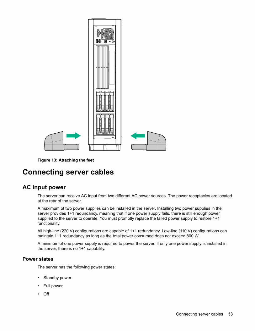
Figure 13: Attaching the feet
Connecting server cables
AC input powerThe server can receive AC input from two different AC power sources. The power receptacles are locatedat the rear of the server.
A maximum of two power supplies can be installed in the server. Installing two power supplies in theserver provides 1+1 redundancy, meaning that if one power supply fails, there is still enough powersupplied to the server to operate. You must promptly replace the failed power supply to restore 1+1functionality.
All high-line (220 V) configurations are capable of 1+1 redundancy. Low-line (110 V) configurations canmaintain 1+1 redundancy as long as the total power consumed does not exceed 800 W.
A minimum of one power supply is required to power the server. If only one power supply is installed inthe server, there is no 1+1 capability.
Power statesThe server has the following power states:
• Standby power
• Full power
• Off
Connecting server cables 33
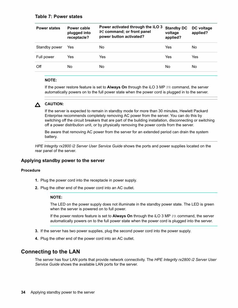
Table 7: Power states
Power states Power cableplugged intoreceptacle?
Power activated through the iLO 3PC command; or front panelpower button activated?
Standby DCvoltageapplied?
DC voltageapplied?
Standby power Yes No Yes No
Full power Yes Yes Yes Yes
Off No No No No
NOTE:
If the power restore feature is set to Always On through the iLO 3 MP PR command, the serverautomatically powers on to the full power state when the power cord is plugged in to the server.
CAUTION:
If the server is expected to remain in standby mode for more than 30 minutes, Hewlett PackardEnterprise recommends completely removing AC power from the server. You can do this byswitching off the circuit breakers that are part of the building installation, disconnecting or switchingoff a power distribution unit, or by physically removing the power cords from the server.
Be aware that removing AC power from the server for an extended period can drain the systembattery.
HPE Integrity rx2800 i2 Server User Service Guide shows the ports and power supplies located on therear panel of the server.
Applying standby power to the server
Procedure
1. Plug the power cord into the receptacle in power supply.
2. Plug the other end of the power cord into an AC outlet.
NOTE:
The LED on the power supply does not illuminate in the standby power state. The LED is greenwhen the server is powered on to full power.
If the power restore feature is set to Always On through the iLO 3 MP PR command, the serverautomatically powers on to the full power state when the power cord is plugged into the server.
3. If the server has two power supplies, plug the second power cord into the power supply.
4. Plug the other end of the power cord into an AC outlet.
Connecting to the LANThe server has four LAN ports that provide network connectivity. The HPE Integrity rx2800 i2 Server UserService Guide shows the available LAN ports for the server.
34 Applying standby power to the server

Procedure
1. Obtain valid IP addresses for each LAN port you plan to activate.
2. Connect the LAN cable from an available LAN port into a live connection on the network.
Setting up the systemFor more information on using the iLO 3 MP, see the HPE Integrity iLO 3 Operations Guide.
Setup checklistUse the Setup checklist while setting up the HPE Integrity iLO 3.
Table 8: Setup checklist
Step Action Procedure Status
Standard setup
1 Preparation1. Determine an access method to select and
connect the cables.
2. Determine a LAN configuration method andassign an IP address if necessary.
2 Configure the iLO 3 MPLAN
Select one of the three methods to configure theLAN for iLO 3 MP access:
• DHCP with DNS
• RS-232 serial port
• Static IP address
3 Log on to the iLO 3 MP Log on to the iLO 3 MP from a supported webbrowser or command line using the default username and password.
4 Change default username and password
Change the default user name and password on theadministrator account to your predefined selections.
5 Set up user accounts Set up the user accounts if you are using the localaccounts feature.
6 Set up security access Set up the security access settings.
Accessing UEFI or the OS from iLO MPThe Unified Extensible Firmware Interface is an architecture that provides an interface between theserver OS and the server firmware. UEFI provides a standard environment for booting an OS and runningpreboot applications.
Setting up the system 35
Use this procedure to access UEFI or the OS from the iLO MP. Your security parameters were setregarding remote access.
NOTE:
Commands are case-insensitive.
Procedure
1. From the MP Main Menu, enter co to access the Console.
NOTE:
Terminal windows must be set to a window size of 80 columns x 25 rows for optimal viewing ofthe console at UEFI.
2. After memory test and CPU late self test the following message appears:
Press Ctrl-C now to bypass loading option ROM UEFI drivers.3. The prompt times out if Ctrl-C is not pressed within a few seconds. If Ctrl-C is pressed, you are
presented with two options: After selecting an option, the boot proceeds.
NOTE:
If no option is selected, the boot proceeds after ten seconds.
• Bypass loading from I/O slots.
• Bypass loading from I/O slots and core I/O.
The Bypass loading from I/O slots and core I/O option may be useful if a bad core I/O UEFI driveris preventing system boot. USB drives can still be used at the UEFI shell to update core I/O drivers.
CAUTION:
Pressing
Ctrl-C before the prompt does not work and might disable this feature. Therefore, be sure towait for the prompt before pressing Ctrl-C.
NOTE: The prompt might take several minutes to appear, and the period that you can pressCtrl-C is very short. For typical boots, Hewlett Packard Enterprise recommends that you letthe prompt time out.
4. Depending on how the server was configured from the factory and if the OS is installed at the time ofpurchase, you are taken to:
a. UEFI shell prompt
b. OS login prompt
5. If the server has a factory-installed OS, you can interrupt the boot process to configure your specificUEFI parameters.
36 Installing the server
6. If you are at the UEFI shell prompt, go to UEFI Front Page.
7. If you are at the OS login prompt, go to OS login prompt.
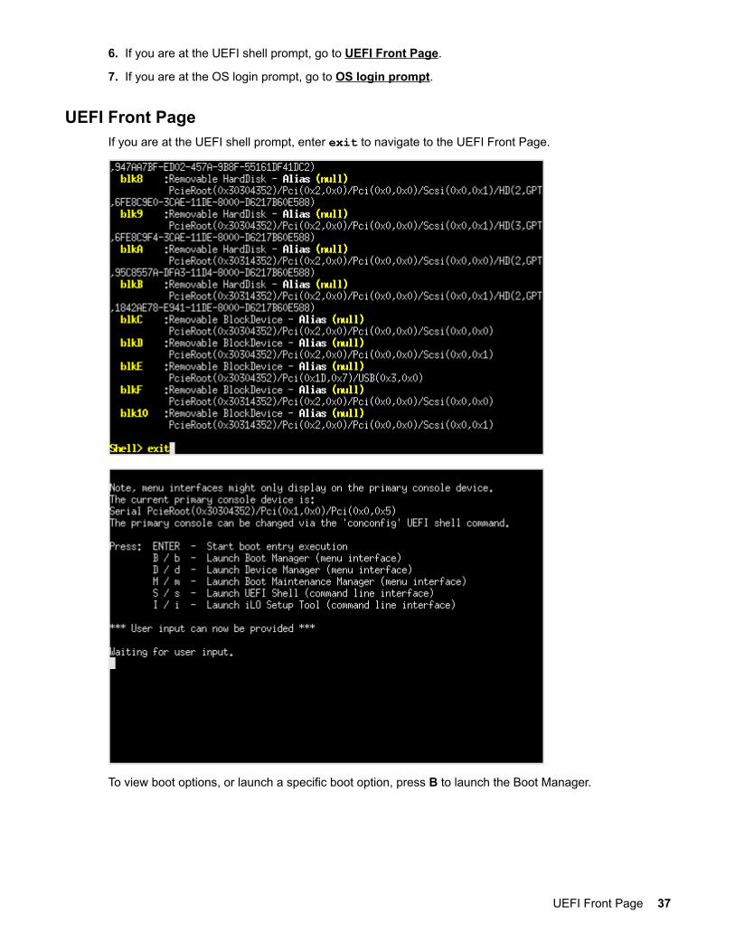
UEFI Front PageIf you are at the UEFI shell prompt, enter exit to navigate to the UEFI Front Page.
To view boot options, or launch a specific boot option, press B to launch the Boot Manager.
UEFI Front Page 37
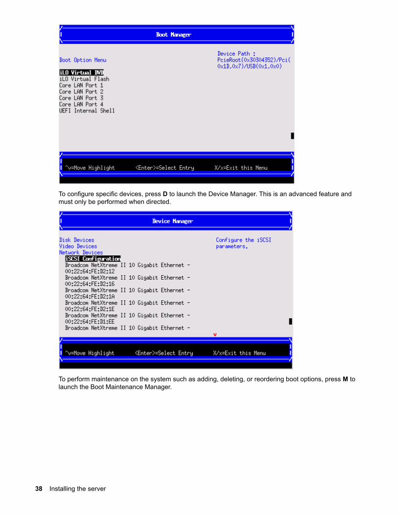
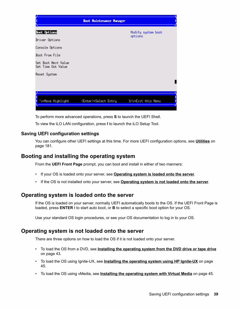
To configure specific devices, press D to launch the Device Manager. This is an advanced feature andmust only be performed when directed.
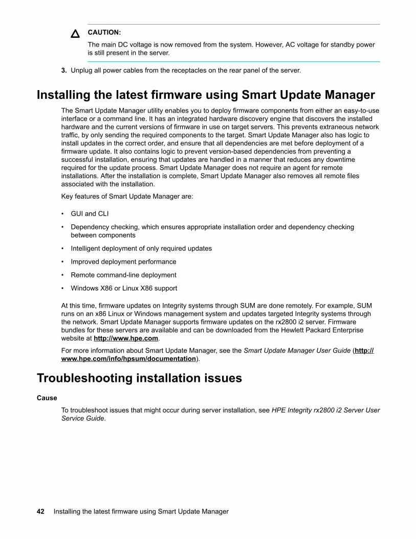
To perform maintenance on the system such as adding, deleting, or reordering boot options, press M tolaunch the Boot Maintenance Manager.
38 Installing the server
To perform more advanced operations, press S to launch the UEFI Shell.
To view the iLO LAN configuration, press I to launch the iLO Setup Tool.
Saving UEFI configuration settingsYou can configure other UEFI settings at this time. For more UEFI configuration options, see Utilities onpage 181.
Booting and installing the operating systemFrom the UEFI Front Page prompt, you can boot and install in either of two manners:
• If your OS is loaded onto your server, see Operating system is loaded onto the server.
• If the OS is not installed onto your server, see Operating system is not loaded onto the server.
Operating system is loaded onto the serverIf the OS is loaded on your server, normally UEFI automatically boots to the OS. If the UEFI Front Page isloaded, press ENTER t to start auto boot, or B to select a specific boot option for your OS.
Use your standard OS login procedures, or see your OS documentation to log in to your OS.
Operating system is not loaded onto the serverThere are three options on how to load the OS if it is not loaded onto your server.
• To load the OS from a DVD, see Installing the operating system from the DVD drive or tape driveon page 43.
• To load the OS using Ignite-UX, see Installing the operating system using HP Ignite-UX on page45.
• To load the OS using vMedia, see Installing the operating system with Virtual Media on page 45.
Saving UEFI configuration settings 39

OS login promptIf your server is at the OS login prompt after you establish a connection to the server, use your standardOS log in procedures, or see your OS documentation for the next steps.
Powering on and powering off the server
Power statesThe server has the following power states:
• Standby power
• Full power
• Off
For details about server power states, see Power states.
NOTE:
If the power restore feature is set to Always On through the iLO 3 MP PR command, the serverautomatically powers on to the full power state when the power cord is plugged in to the server.
Powering on the serverPower on the server to full power using the following methods if the server is in the standby power state:
• iLO 3 MP PC command
• Power button
Powering on the server using the iLO 3 MP
NOTE:
If the power restore feature is set to
Always On through the iLO 3 MP PR command, the server automatically powers on to the fullpower state when the power cord is plugged in to the server.
Procedure
1. Plug all power cables into the receptacles on the rear panel of the server.
2. Initiate a console session, and access the MP Main Menu.
3. Enter CM to enable command mode.
4. Enter PC to use the remote power control command.
5. Enter ON to power on the server, and enter YES when prompted to confirm the action.
6. Start the operating system.
7. For more information, see the operating system documentation.
40 OS login prompt

Powering on the server manually
NOTE: If the power restore feature is set to Always On through the iLO 3 MP PR command, theserver automatically powers on to the full power state when the power cord is plugged in to theserver.
Procedure
1. Plug all power cables into the receptacles on the rear panel of the server.
2. Press the power button to start the server.
3. Start the operating system. For more information, see the operating system documentation.
Powering off the serverIf the server is in the standby or full power state, power off the server by using either of the followingmethods:
• iLO 3 MP PC command
• Power button
Powering off the server using the iLO 3 MP
Procedure
1. Gracefully shut down the operating system. See the operating system documentation for moreinformation.
2. Initiate a console session, and access the MP Main Menu.
3. Enter CM to enable command mode.
4. Enter PC to use the remote power control command.
5. Enter OFF to power off the server, and enter YES when prompted to confirm the action.
CAUTION:
The main DC voltage is now removed from the system However, AC voltage for standby poweris still present in the server.
6. Unplug all power cables from the receptacles on the rear panel of the server.
Powering off the server manually
Procedure
1. Gracefully shut down the operating system. For more information, see the operating systemdocumentation.
2. To power off the server, press the power button.
Powering on the server manually 41
CAUTION:
The main DC voltage is now removed from the system. However, AC voltage for standby poweris still present in the server.
3. Unplug all power cables from the receptacles on the rear panel of the server.
Installing the latest firmware using Smart Update ManagerThe Smart Update Manager utility enables you to deploy firmware components from either an easy-to-useinterface or a command line. It has an integrated hardware discovery engine that discovers the installedhardware and the current versions of firmware in use on target servers. This prevents extraneous networktraffic, by only sending the required components to the target. Smart Update Manager also has logic toinstall updates in the correct order, and ensure that all dependencies are met before deployment of afirmware update. It also contains logic to prevent version-based dependencies from preventing asuccessful installation, ensuring that updates are handled in a manner that reduces any downtimerequired for the update process. Smart Update Manager does not require an agent for remoteinstallations. After the installation is complete, Smart Update Manager also removes all remote filesassociated with the installation.
Key features of Smart Update Manager are:
• GUI and CLI
• Dependency checking, which ensures appropriate installation order and dependency checkingbetween components
• Intelligent deployment of only required updates
• Improved deployment performance
• Remote command-line deployment
• Windows X86 or Linux X86 support
At this time, firmware updates on Integrity systems through SUM are done remotely. For example, SUMruns on an x86 Linux or Windows management system and updates targeted Integrity systems throughthe network. Smart Update Manager supports firmware updates on the rx2800 i2 server. Firmwarebundles for these servers are available and can be downloaded from the Hewlett Packard Enterprisewebsite at http://www.hpe.com.
For more information about Smart Update Manager, see the Smart Update Manager User Guide (http://www.hpe.com/info/hpsum/documentation).
Troubleshooting installation issuesCause
To troubleshoot issues that might occur during server installation, see HPE Integrity rx2800 i2 Server UserService Guide.
42 Installing the latest firmware using Smart Update Manager

Operating system procedures
Operating systems supported on the server• HP-UX 11i v3 HWE 1009 or later
• HPE OpenVMS v8.4 with VMS84I_UPDATE-V0500, rx2800 i2 enablement kit
• Windows Server 2008 Itanium Edition R2
NOTE:
Wake-On-LAN (WOL) is supported with the rx2800 i2 server running HP-UX 11i v3. WOL is notsupported with Integrity servers running Windows or OpenVMS environments. The supportedremote power-on solution for Windows and OpenVMS environments is iLO 3.
Installing the operating system onto the serverThe following procedures describe generalized operating system installation. For more details, see theoperating system documentation.
Installing the operating system from the DVD drive or tape drive
NOTE:
Commands are not case-sensitive.
NOTE:
Tapeboot requires rx2800 i2 server system firmware bundle 26.12 or later and an additionalAM311A Integrity Smart Array P411/256 HBA running 5.06 firmware or later.
Procedure
1. Insert the OS Media into the DVD (internal to system) or tape drive (external to system).
2. Power on the server and boot to UEFI. If the server is already powered on, use the reset commandat the UEFI prompt to reboot to UEFI.
3. From the UEFI front page, press S to launch the UEFI Shell.
NOTE:
If the device is already selected or you already know the device name, skip the following step.
4. If you are using a tape device, when the UEFI shell comes up, you will see a message similar to thefollowing on the console:
HP Smart Array P411 Controller (version 5.06) Tape Drive(s) Detected: Port: 2E, box:0, bay: 5 (SAS)
Operating system procedures 43
NOTE: If you do not see a line starting with Port and ending with (SAS), the tape is notconnected correctly or it is not responding.
5. Locate the device you want to boot from.
a. For DVD, locate the device:
I. To list all device names from the UEFI Shell prompt, use the map command.
II. From the list generated by the map command, locate the device name (in this example, fs6).
III. fs2:\> mapDevice mapping table
fs6 :Removable CDRom - Alias cd66d0a blk6 PcieRoot(0x30304352)/Pci(0x1D,0x7)/USB(0x3,0x0)/CDROM(0x0)
IV. NOTE:
Your DVD drive might not be named fs6. Make sure that you verify the ID appropriateto your DVD device.
V. At the UEFI shell prompt, specify the device name for the DVD-ROM.
VI. Enter the appropriate UEFI install command, as in the following example:
VII. HP-UX
Shell> fs6:fs6:\> installOpenVMS
Shell> fs0:fs0:\> cd efi\bootfs0:\efi\boot> bootia64
b. For tape, locate the device:
I. To boot from tape once you are at the UEFI shell:
II. Shell> tapeboot select01 PcieRoot(0x30304352)/Pci(0x8,0x0)/Pci(0x0,0x0)/SAS(0x50060B00007F6FFC,0x0,0x1,NoTopology,0,0,0,0x0)Select Desired Tape: 01 <<input 01
• If the correct media is installed, it will boot from tape when you enter the index number.
• If there is no media in the SAS tape drive and you select 1, the following message appears:
tapeboot: Could not load tapeboot image
6. The operating system starts loading onto the server.
7. To complete the OS installation, follow the on-screen instructions.
8. Once the installation has completed, review the Configuring system boot options on page 45.
44 Operating system procedures

NOTE: For OpenVMS installation, see the VMS84I_UPDATE-V0500.RELEASE_NOTESdocument available on the Hewlett Packard Enterprise Support Center at http://www.hpe.com/support/hpesc.
Installing the operating system using HP Ignite-UXIgnite-UX is an HP-UX administration toolset that enables:
• Simultaneous installation of HP-UX on multiple clients
• The creation and use of custom installations
• The creation of recovery media
• The remote recovery of clients
To install the OS onto the server using Ignite-UX, go to http://www.hpe.com/info/ignite-ux.
Installing HPE OpenVMS with Infoserver UtilityInfoserver Utility enables OpenVMS installations and upgrades over the network. To install the OS usingInfoserver, see the "Setting Up and Performing Network Booting" section in HPE OpenVMS Version 8.4Upgrade and Installation Manual on the Hewlett Packard Enterprise website:
http://www.hpe.com/support/hpesc (search for the manual title or product name).
Installing the operating system with Virtual Media
NOTE:
Installing the OS with Virtual Media (vMedia) might be significantly slower than installing using othermethods.
Using vMedia enables connections of a DVD physical device or image file from the local client system tothe remote server. The virtual device or image file can be used to boot the server with an operatingsystem that supports USB devices.
Using vMedia depends on a reliable network with good bandwidth, which is especially important whenyou are performing tasks such as large file transfers or OS installations.
For more information regarding loading the OS with vMedia, see the HPE Integrity iLO 3 OperationsGuide.
NOTE:
After the OS is loaded, to preserve boot entries in case of failure, make sure to save yournonvolatile memory settings.
Configuring system boot options• Boot Manager
Contains the list of boot options available. Ordinarily, the boot options list includes the UEFI InternalShell and one or more operating system loaders.
Installing the operating system using HP Ignite-UX 45
To manage the boot options list for each server, use the UEFI Shell, the Boot Maintenance Manager,or operating system utilities.
• Autoboot setting
The autoboot setting determines whether a server automatically loads the first item in the bootoptions list or remains at the UEFI Front Page menu. With autoboot enabled, UEFI loads the first itemin the boot options list after a designated timeout period.
Configure the autoboot setting for an HPE Integrity server using either the UEFI Shell autobootcommand or the Set Time Out Value menu item from the Boot Maintenance Manager.
Examples of autoboot commands for HP-UX:
◦ Disable autoboot from the UEFI Shell by issuing autoboot off,
◦ Enable autoboot with the default timeout value by issuing autoboot on,
◦ Enable autoboot with a timeout of 60 seconds by issuing autoboot 60,
◦ Set autoboot from HP-UX using setboot,
◦ Enable autoboot from HP-UX using setboot -b on,
◦ Disable autoboot from HP-UX using setboot -b off.
For more information on the autoboot command, enter help autoboot.
Booting and shutting down HP-UX• To add an HP-UX entry to the boot options list, see Adding HP-UX to the boot options list.
• To boot HP-UX, use one of the following procedures:
◦ To boot HP-UX in the standard mode, see HP-UX standard boot. HP-UX boots in multi-usermode.
◦ To boot HP-UX in single-user mode, see Booting HP-UX in single-user mode.
◦ To boot HP-UX in LVM-maintenance mode, see Booting HP-UX in LVM-maintenance mode.
• To shut down the HP-UX operating system, see Shutting down HP-UX.
Adding HP-UX to the boot options listYou can add the \EFI\HPUX\HPUX.EFI loader to the boot options list from the UEFI Shell or the BootMaintenance Manager.
NOTE:
On Integrity servers, the operating system installer automatically adds an entry to the boot optionslist.
NOTE: To add an HP-UX boot option when logged in to HP-UX, use the setboot command. Fordetails, see the setbootvolume(1M) manpage.
To add HP-UX to the list:
46 Booting and shutting down HP-UX
NOTE:
Commands are not case-sensitive.
Procedure
1. Access the UEFI Shell environment.
a. Log in to iLO for Integrity, and then to access the system console, enter CO.
When accessing the console, confirm that you are at the UEFI Front Page.
If you are at another UEFI menu, then choose the Exit option, or press X to exit the menu. Exit untilyou return to the screen that lists the keys that can be pressed to launch various Managers.
b. To launch the UEFI shell, press S.
2. Access the UEFI System Partition (fsX: where X is the file system number) for the device from whichyou want to boot HP-UX.
3. For example, to access the UEFI System Partition for the bootable file system number 2, enter fs2:.The UEFI Shell prompt changes to reflect the file system currently accessed.
4. The full path for the HP-UX loader is \EFI\HPUX\HPUX.EFI and is on the device you are accessing.
5. At the UEFI Shell environment, use the bcfg command to manage the boot options list.
6. The bcfg command includes the following options for managing the boot options list:
a. bcfg boot dump–Display all items in the boot options list for the server.
b. bcfg boot rm #–Remove the item number specified by # from the boot options list.
c. bcfg boot mv #a #b–Move the item number specified by #a to the position specified by #b in the boot options list.
d. bcfg boot add # file.EFI "Description"–Add a new boot option to the position in the boot options list specified by #. The new boot optionreferences file.EFI and is listed with the title specified by Description.
For example, bcfg boot add 1 \EFI\HPUX\HPUX.EFI "HP-UX 11i v3" adds an HP-UX11i v3 item as the first.
7. For details, see the help bcfg command.
8. Exit the console and iLO MP interfaces.
9. Press Ctrl-B to exit the system console and return to the iLO 3 MP Main Menu. To exit the MP, at theMain Menu, enter X.
HP-UX standard bootUse either of the following procedures to boot HP-UX:
HP-UX standard boot 47
• Booting HP-UX from the UEFI Boot Manager on page 48
• Booting HP-UX from the UEFI Shell on page 48
Booting HP-UX from the UEFI Boot Manager
Procedure
1. From the UEFI Boot Manager menu, choose an item from the boot options list to boot HP-UX.
2. Access the UEFI Boot Manager menu for the server on which you want to boot HP-UX.
3. Log in to iLO MP, and then to choose the system console, enter CO.
4. Confirm you are at the UEFI Front Page. If you are at another UEFI menu, then to exit the menu,choose the Exit option or press X. Exit until you return to the screen that lists the keys that can bepressed to launch various Managers. To launch the Boot Manager, press B.
5. At the UEFI Boot Manager menu, choose an item from the boot options list.
Each item in the boot options list references a specific boot device and provides a specific set of bootoptions or arguments you use when booting the device.
6. To initiate booting using your chosen boot option, press Enter.
7. Exit the console and iLO MP interfaces.
8. To exit the system console and return to the MP Main Menu, press Ctrl-B. To exit the MP Main Menu,enter X at the MP Main Menu.
Booting HP-UX from the UEFI Shell
Procedure
1. Access the UEFI Shell.
2. From the UEFI Front Page, press S to launch the UEFI shell.
3. Use the map command to list the file systems (fs0, fs1, and so on) that are known and have beenmapped.
4. To select a file system to use, enter the mapped name followed by a colon (:). For example, to operatewith the boot device that is mapped as fs0, at the UEFI Shell prompt, enter fs0:.
5. To launch the HPUX.EFI loader from the currently selected boot device, at the UEFI Shell commandprompt, enter HPUX.
If needed, specify the full path of loader by entering \EFI\HPUX\HPUX at the UEFI Shell commandprompt.
By default, the HPUX.EFI loader boots using the loader commands found in the \EFI\HPUX\AUTOfile on the UEFI System Partition of the selected boot device. The AUTO file typically contains the bootvmunix command.
To interact with the HPUX.EFI loader, interrupt the boot process (for example, enter a space) withinthe time-out period provided by the loader. To exit the loader, use the exit command, which returnsyou to UEFI.
48 Booting HP-UX from the UEFI Boot Manager

Booting HP-UX in single-user mode
Procedure
1. Use steps 1–5 from Booting HP-UX from the UEFI Shell on page 48 to access the UEFI shell, andlaunch the HPUX.UEFI loader.
2. Access the HP-UX Boot Loader prompt (HPUX>) by pressing any key within the 10 seconds given forinterrupting the HP-UX boot process. Use the HPUX.EFI loader to boot HP-UX in single-user mode instep 3.
After you press a key, the HPUX.EFI interface (the HP-UX Boot Loader prompt, HPUX>) launches. Forhelp using the HPUX.EFI loader, enter the help command. To return to the UEFI Shell, enter exit.
3. At the HPUX.EFI interface (the HP-UX Boot loader prompt, HPUX>) enter the boot -is vmunixcommand to boot HP-UX (the /stand/vmunix kernel) in single-user (-is) mode.
Booting HP-UX in LVM-maintenance modeThe procedure for booting HP-UX into LVM Maintenance Mode is the same as for booting into single usermode (Booting HP-UX in single-user mode on page 49), except use the -lm boot option instead of the-is boot option:
HPUX> boot -lm vmunix
Shutting down HP-UXFor more information, see the shutdownvolume(1M) manpage.
To shut down HP-UX running on a server:
Procedure
1. Log in to HP-UX running on the server that you want to shut down, or log in to iLO MP for the serverand use the Console menu to access the system console. Accessing the console through iLO MPenables you to maintain console access to the server after HP-UX has shut down.
2. Use the shutdown command with the appropriate command-line options.
The command-line options you specify determines the way in which HP-UX shuts down and whetherthe server is rebooted.
Choose an HP-UX shutdown option for your server:
• To shut down HP-UX and halt (power off) the server, use the shutdown -h command.
To reboot a halted server, power on the server by using the PC command at the iLO MP Commandmenu.
• To shut down HP-UX and reboot the server, use the shutdown -r command.
Booting and shutting down OpenVMS
Booting HP-UX in single-user mode 49
Adding OpenVMS to the Boot Options list
NOTE: If OpenVMS is already installed on the server, add OpenVMS to the boot options list byusing the SYS$MANAGER:BOOT_OPTIONS.COM command procedure, and follow the on-screeninstructions.
NOTE:
Commands are not case-sensitive.
Procedure
1. Access the UEFI Shell environment.
a. Log in to iLO for Integrity, and then to access the system console, enter CO.
When accessing the console, confirm that you are at the UEFI Front Page.
If you are at another UEFI menu, choose the Exit option or press X to exit the menu. Exit until youreturn to the screen that lists the keys that can be pressed to launch various Managers.
b. To launch the UEFI shell, press S.
2. Access the UEFI System Partition (fsX: where X is the file system number) for the device from whichyou want to boot OpenVMS.
3. For example, to access the UEFI System Partition for the bootable file system number 2, enter fs2:.The UEFI Shell prompt changes to reflect the file system currently accessed.
4. The full path for the loader is \EFI\VMS\VMS_LOADER.EFI and is on the device you are accessing.
5. At the UEFI Shell environment, to manage the boot options list, use the bcfg command.
6. The bcfg command includes the following options for managing the boot options list:
a. bcfg boot dump–Display all items in the boot options list for the server.
b. bcfg boot rm #–Remove the item number specified by # from the boot options list.
c. bcfg boot mv #a #b–Move the item number specified by #a to the position specified by #b in the boot options list.
d. bcfg boot add # file.efi "Description".–Add a new boot option to the position in the boot options list specified by #. The new boot optionreferences file.efi and is listed with the title specified by Description.
For example, bcfg boot add 1 \EFI\VMS\VMS_LOADER.EFI "OpenVMS V8.4" adds an OpenVMSitem as the first entry in the boot options list.
7. For details, see the help bcfg command.
8. Exit the console and iLO MP interfaces.
9. Press Ctrl-B to exit the system console and return to the MP Main Menu. To exit the MP Main Menu,press X.
50 Adding OpenVMS to the Boot Options list
For more details, see the HPE OpenVMS 8.4 Upgrade and Installation Manual.
Booting OpenVMSTo boot OpenVMS, use either of the following procedures:
• Booting OpenVMS from the UEFI Boot Manager on page 51
• Booting OpenVMS from the UEFI Shell on page 51
Booting OpenVMS from the UEFI Boot Manager
Procedure
1. From the UEFI Boot Manager menu, using the chosen boot option, choose an item from the bootoptions list to boot OpenVMS.
2. Access the UEFI Boot Manager menu for the server on which you want to boot OpenVMS.
3. Log in to the iLO MP, and then to choose the system console, enter CO.
4. Confirm that you are at the UEFI Front Page. If you are at another UEFI menu, then to exit the menu,choose the Exit option or press X. Exit until you return to the screen that lists the keys that can bepressed to launch various Managers. Press B to launch the Boot Manager.
5. At the EFI Boot Manager menu, choose an item from the boot options list.
6. Each item in the boot options list refers to a specific boot device and provides a specific set of bootoptions or arguments to use when booting the device.
7. To initiate booting using the chosen boot option, press Enter.
8. Exit the console and iLO MP interfaces.
9. Press Ctrl-B to exit the system console and return to the MP Main Menu. To exit the MP Main Menu,press X.
Booting OpenVMS from the UEFI ShellFrom the EFI Shell environment, to boot OpenVMS on a device, first access the bootable partition (forexample fs0:) for the root device and, then enter\efi\vms\vms_loader to initiate the OpenVMSloader.
Procedure
1. Access the UEFI Shell.
2. From the UEFI Front Page, press S to launch the UEFI shell.
3. Use the map command to list the file systems (fs0, fs1, and so on) that are known and have beenmapped.
4. To select a file system to use, enter the mapped name followed by a colon (:). For example, to operatewith the boot device that is mapped as fs0, at the UEFI Shell prompt, enter fs0:.
5. When accessing the bootable partition for the desired boot device, issue the\efi\vms\vms_loadercommand to initiate the vms_loader.efi loader on the device you are accessing.
fs5:> \efi\vms\vms_loader.efifs5:> \efi\vms\vms_loader.efi
Booting OpenVMS 51
HP OpenVMS Industry Standard 64 Operating System, Version V8.4© Copyright 1976-2010 Hewlett-Packard Development Company, L.P.
6. Exit the console and iLO MP interfaces.
7. Press Ctrl-B to exit the system console and return to the MP Main Menu. To exit the MP Main Menu,press X.
Shutting down OpenVMS
Procedure
1. Log in to OpenVMS running on the server that you want to shut down.
2. Log in to the iLO MP for the server, and then to access the system console, use the Console menu.Accessing the console through the iLO MP enables you to maintain console access to the server afterOpenVMS has shut down.
3. At the OpenVMS DCL prompt, enter the @SYS$SYSTEM:SHUTDOWN command, and then specify theshutdown options in response to the prompts given.
NOTE: Use the command in step 2 when you shut down OpenVMS for the first time. If you haveshut down OpenVMS more than once, use the $ shutdown command.
$ @sys$system:shutdown
SHUTDOWN -- Perform an Orderly System Shutdown on node OVMSHow many minutes until final shutdown [0]:Reason for shutdown [Standalone]:Do you want to spin down the disk volumes [NO]?Do you want to invoke the site-specific shutdown procedure [YES]?Should an automatic system reboot be performed [NO]?When will the system be rebooted [later]:Shutdown options (enter as a comma-separated list):REBOOT_CHECK Check existence of basic system filesSAVE_FEEDBACK Save AUTOGEN feedback information from this bootDISABLE_AUTOSTART Disable autostart queuesPOWER_OFF Request console to power-off the systemBIB_STATE Request console to reboot all CPUs to the Itanium BIB state
Shutdown options [NONE]:
Booting and shutting down Microsoft Windows operatingsystems
52 Shutting down OpenVMS

Adding Microsoft Windows operating systems to the boot options list
NOTE:
On Integrity servers, the operating system installer automatically adds an entry to the boot optionslist.
NOTE:
Commands are not case-sensitive.
Procedure
1. Access the UEFI Shell environment.
a. Log in to iLO for Integrity, and then to access the system console, enter CO.
When accessing the console, confirm that you are at the UEFI Front Page.
If you are at another UEFI menu, then to exit the menu, choose the Exit option or press X. Exit untilyou return to the screen that lists the keys that can be pressed to launch various Managers.
b. Press S to launch the UEFI shell.
2. Access the UEFI System Partition (fsX: where X is the file system number) for the device from whichyou want to boot your Windows operating system.
3. For example, to access the UEFI System Partition for the bootable file system number 2, enter fs2:.The UEFI Shell prompt changes to reflect the file system currently accessed.
4. The full path for the Microsoft Windows loader is \efi\microsoft\winnt50\ ia64ldr.efi andis on the device you are accessing.
5. Use the ls command to list the contents of the \EFI\Microsoft\WINNT50 directory to identify thename of the Windows boot option file (Boot00nn) that you want to import into the system boot optionslist.
fs0:\> ls EFI\Microsoft\WINNT50Directory of: fs0:\EFI\Microsoft\WINNT5009/18/03 11:58a <DIR> 1,024 .09/18/03 11:58a <DIR> 1,024 ..12/18/03 08:16a 354 Boot 0001 1 File(s) 354 bytes 2 Dir(s)
fs0:\>6. Use the \MSUtil\nvrboot.efi command to launch the Microsoft Windows boot options utility.
fs0:\> msutil\nvrboot
NVRBOOT: OS Boot Options Maintenance Tool [Version 5.2.3683]
1. SUSE SLES 10 2. HP-UX Primary Boot: 0/0/1/0/0.2.0 * 3. Windows Server 2003, Datacenter 4. EFI Shell [Built-in]
* = Windows OS boot option
Adding Microsoft Windows operating systems to the boot options list 53
(D)isplay (M)odify (C)opy E(x)port (I)mport (E)rase (P)ush (H)elp (Q)uit
Select>7. Use the Import command to import the Window boot option file.
Select> iEnter IMPORT file path: \EFI\Microsoft\WINNT50\Boot0001Imported Boot Options from file: \EFI\Microsoft\WINNT50\Boot0001
Press enter to continue
NOTE:
Your output might not exactly match the output shown here.
8. Enter Q to quit the NVRBOOT utility.
9. Exit the console and iLO MP interfaces. Press Ctrl-B to exit the system console and return to the iLOMP Main Menu. To exit the MP, enter X at the Main Menu.
Booting the Microsoft Windows operating systemUse UEFI Boot Manager menu to choose the appropriate Windows item from the boot options list. See Shutting down Microsoft Windows on page 55 for details on shutting down the Windows operatingsystem.
Procedure
1. From the UEFI Boot Manager choose an item from the boot options list to boot Windows.
2. Access the UEFI Boot Manager menu for the server on which you want to boot Windows.
3. Log in to the iLO MP, and then to choose the system console, enter CO.
4. Confirm that you are at the UEFI Boot Manager menu (the main UEFI menu). If you are at anotherUEFI menu, choose the Exit option from the submenus until you return to the screen with the UEFIBoot Manager heading.
5. At the UEFI Boot Manager menu, choose an item from the boot options list. Each item in the bootoptions list references a specific boot device and provides a specific set of boot options or argumentsto be used when booting the device.
6. Press Enter to initiate booting using the chosen boot option.
7. After the Windows operating system begins loading, wait for the SAC to become available.
8. The SAC interface provides a text-based administration tool that is available from the systemconsole. For details, see the SAC online help (enter ? at the SAC> prompt).
Loading.: Windows Server 2003, DatacenterStarting: Windows Server 2003, Datacenter
Starting Windows...********************************************************************************
Computer is booting, SAC started and initialized.
Use the "ch -?" command for information about using channels.
54 Booting the Microsoft Windows operating system

Use the "?" command for general help.
SAC>
NOTE:
Your output might not exactly match the output shown here.
9. Exit the console and iLO MP interfaces when finished using them.
10. Enter Ctrl-B to exit the console and return to the iLO MP Main menu. To exit the iLO MP, enter X atthe Main menu.
Shutting down Microsoft WindowsShut down the Windows operating system on Integrity servers by using the Start menu or the shutdowncommand.
CAUTION:
Do not shut down Windows using SAC restart or shutdown commands under normalcircumstances.
Issuing a restart or a shutdown at the SAC> prompt causes the server to restart or shut downimmediately, and can result in the loss of data.
Instead use the Windows Start menu or the shutdown command to shut down gracefully.
To shut down Windows use either of the following methods.
• Choose Shut Down from the Start menu and choose either Restart or Shut down from the pull-downmenu.
The Restart menu item shuts down and restarts the server. The Shut down menu item shuts down theserver.
You can use this method when using a graphical interface to the server.
• Issue the shutdowncommand from the Windows command line.
You can issue this command from a command prompt through the Special Administration Console orfrom any other command line.
The Windows shutdown command includes the following options:
/sShuts down and halts (power off) the server. This is the equivalent of Start –>Shut Down, Shutdown. To power on the server, use the iLO MP PC command.
/rShuts down and restarts the server. This is the equivalent of Start –>Shut Down, Restart.
/aAborts a server shutdown.
/t xxxSets the timeout period before shutdown to xxx seconds. The timeout period ranges from 0–600,with a default of 30.
Shutting down Microsoft Windows 55
For details, see the help shutdownWindows command.
Shutting down Windows operating systems from the command lineFrom the Windows command line, issue the shutdown command to shut down the operating system.
Procedure
1. Log in to your Windows operating system running on the server that you want to shut down.
2. For example, access the system console and use the Windows Special Administration Consoleinterface to start a command prompt, from which you can issue Windows commands to shut down theserver.
3. Check to see whether any users are logged in.
4. Use the query user or query session command.
5. Issue the shutdown command and the appropriate options to shut down the Windows Server 2003 onthe server.
6. You have the following options when shutting down Windows:
a. To shut down Windows and reboot:shutdown /r or choose the Start —> Shut Down action and choose Restart from the pull-downmenu.
b. To shut down Windows and halt (power off server hardware):shutdown /s or choose the Start —> Shut Down action and choose Shut down from the pull-down menu. To reboot a halted server you must power on the server using the PC command at theiLO MP Command menu.
c. To abort a shutdown (stop a shutdown that has been initiated):shutdown /a.
For example: shutdown /r /t 60 /c "Shut down in one minute."This command initiates a Windows system shutdown and reboot after a timeout period of 60seconds. The /c option specifies a message that is broadcast to any other users of the server.
56 Shutting down Windows operating systems from the command line

Optional componentsThis section describes how to install components into the server that are not factory-installed. If you haveadditional components to install, be sure to install the additional components before installing the serverinto your rack or pedestal configuration. Most servers are pre-configured with all components installedbefore shipping from the Hewlett Packard Enterprise factory.
Externally accessible components:
• SAS hard drives
• Power supplies
Internal components:
• Memory DIMMs
• Processors
• PCIe cards
• SAS cache module and super capacitor pack
WARNING:
Ensure that the system is powered off and all power sources are disconnected from the server priorto removing or installing server hardware (unless you are removing or installing a hot-swappable orhot-pluggable component). Voltage is present at various locations within the server whenever an ACpower source is connected. This voltage is present even when the main power switch is turned off.Failure to observe this warning can result in personal injury or damage to the equipment.
Installing a hot-pluggable SAS hard driveThe front of the server has eight hot-plug SAS hard drive slots. Slots without hard drives installed haveslot fillers installed for cooling purposes.
IMPORTANT:
SAS hard drives are loaded in sequence, starting with the top left slot and proceeding down fillingslots 1, 2, 3, 4 in order; and then filling the right side top to bottom 5, 6, 7, 8. See Front panelcomponents.
Save the hard drive filler for future use. For airflow purposes, place hard drive fillers in slots that donot contain hard drives.
Procedure
1. To remove the hard drive filler, squeeze the tab and then pull out the filler.
Optional components 57
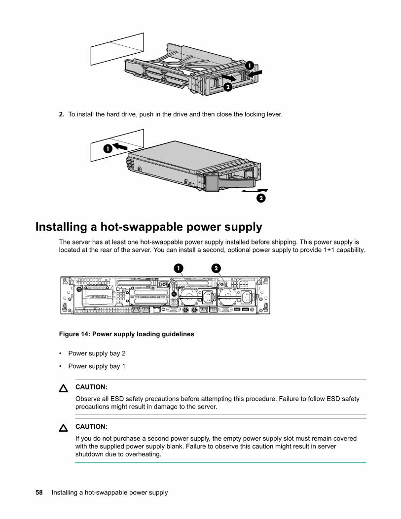
2. To install the hard drive, push in the drive and then close the locking lever.
Installing a hot-swappable power supplyThe server has at least one hot-swappable power supply installed before shipping. This power supply islocated at the rear of the server. You can install a second, optional power supply to provide 1+1 capability.
Figure 14: Power supply loading guidelines
• Power supply bay 2
• Power supply bay 1
CAUTION:
Observe all ESD safety precautions before attempting this procedure. Failure to follow ESD safetyprecautions might result in damage to the server.
CAUTION:
If you do not purchase a second power supply, the empty power supply slot must remain coveredwith the supplied power supply blank. Failure to observe this caution might result in servershutdown due to overheating.
58 Installing a hot-swappable power supply
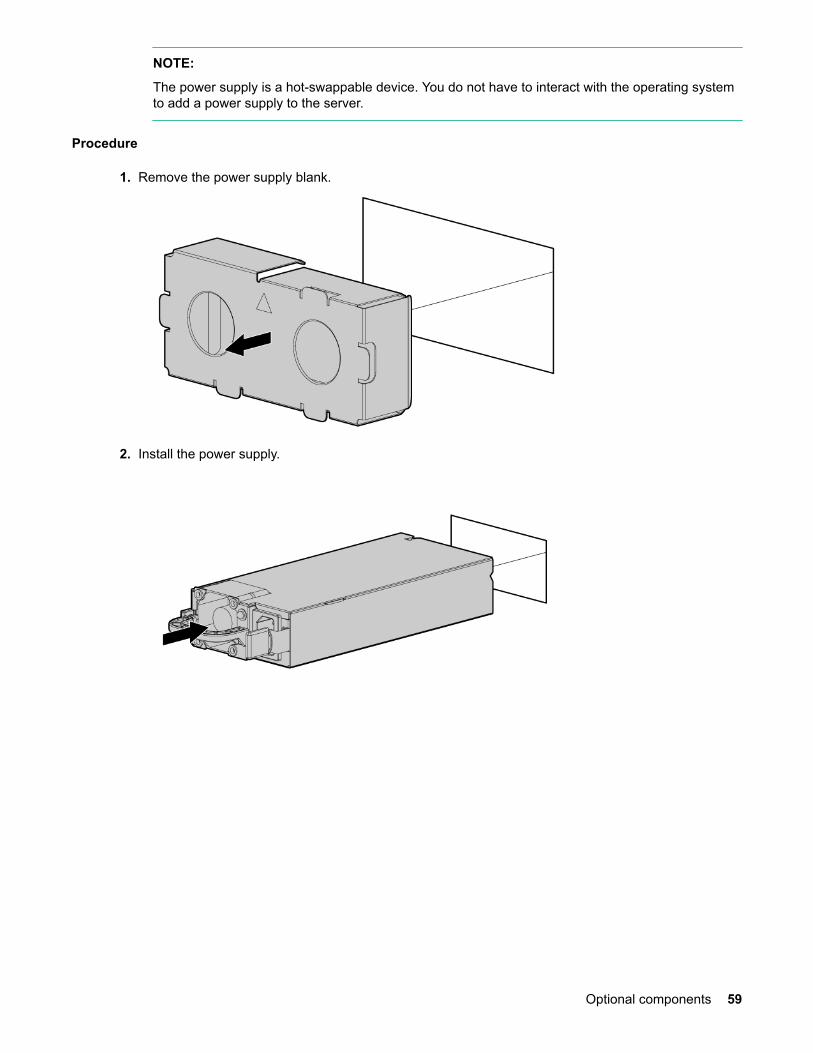
NOTE:
The power supply is a hot-swappable device. You do not have to interact with the operating systemto add a power supply to the server.
Procedure
1. Remove the power supply blank.
2. Install the power supply.
Optional components 59

Removing the access panelProcedure
1. Use the T-15 Torx screwdriver attached to the rear of the server to loosen the security screw on thehood latch.
2. Lift the hood latch handle, and then remove the access panel.
To replace the component, reverse the removal procedure.
Removing the PCI riser cageCAUTION:
For proper cooling, do not operate the server without the access panel, baffles, expansion slotcovers, or blanks installed. If the server supports hot-pluggable components, minimize the amountof time the access panel is open.
Procedure
1. Disconnect any cables connected to optional I/O cards before removing cage.
2. Remove the PCI riser cage.
60 Removing the access panel

To replace the component, reverse the removal procedure. When replacing the PCI riser cage, to ensurethat it has properly seated into the system board, push down on the top of the component where the riseris located.
Removing expansion slot coversCAUTION:
To prevent damage to the server or expansion boards, power off the server, and then remove all ACpower cords before removing or installing the PCI riser cage.
CAUTION:
For proper cooling, do not operate the server without the access panel, baffles, expansion slotcovers, or blanks installed. If the server supports hot-plug components, minimize the amount of timethe access panel is open.
Procedure
1. Remove the access panel (Removing the access panel on page 60).
2. Remove the PCI riser cage (Removing the PCI riser cage on page 60).
3. Remove the expansion slot cover.
a. To remove slot cover 1 or 4, push the retainer to release it, and then slide out the cover.
Removing expansion slot covers 61
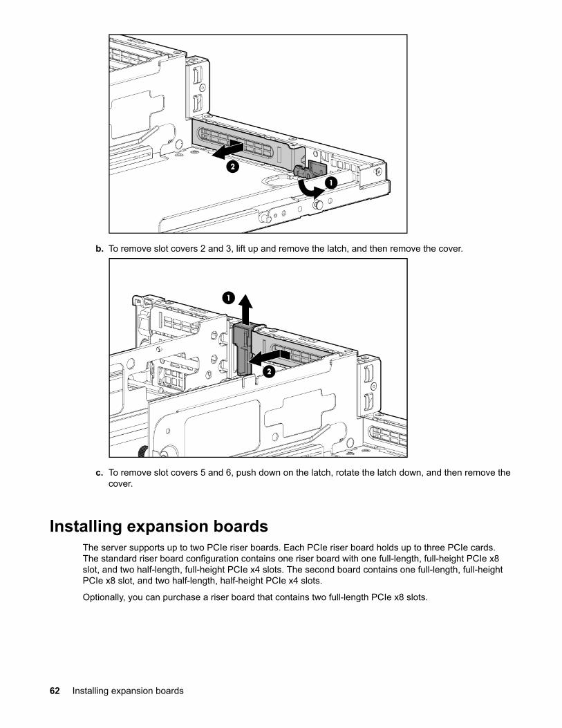
b. To remove slot covers 2 and 3, lift up and remove the latch, and then remove the cover.
c. To remove slot covers 5 and 6, push down on the latch, rotate the latch down, and then remove thecover.
Installing expansion boardsThe server supports up to two PCIe riser boards. Each PCIe riser board holds up to three PCIe cards.The standard riser board configuration contains one riser board with one full-length, full-height PCIe x8slot, and two half-length, full-height PCIe x4 slots. The second board contains one full-length, full-heightPCIe x8 slot, and two half-length, half-height PCIe x4 slots.
Optionally, you can purchase a riser board that contains two full-length PCIe x8 slots.
62 Installing expansion boards

Installing a half-length expansion board
Procedure
1. Remove the access panel. See Removing the access panel on page 60.
2. Remove the PCI riser cage. See Removing the PCI riser cage on page 60.
3. Remove the expansion slot cover. See Removing expansion slot covers on page 61.
4. Install the expansion board.
5. Connect any required internal cables to the expansion board.
6. Reinsert the PCI riser cage into the chassis.
7. Connect any required external cables to the expansion board.
Installing a full-length expansion board
Procedure
1. Remove the access panel. See Removing the access panel on page 60.
2. Remove the PCI riser cage. See Removing the PCI riser cage on page 60.
3. Remove the expansion slot cover. See Removing expansion slot covers on page 61.
4. Install the expansion board.
Installing a half-length expansion board 63

5. Connect any required internal cables to the expansion board.
6. Reinsert the PCI riser cage into the chassis.
7. Connect any required external cables to the expansion board.
Installing DIMMs
Memory configurationsThe server has 24 system memory DIMM slots located on 4 memory expansion boards (6 DIMMs perexpansion board). You can access the memory expansion boards without removing the airflow guide orthe I/O card cage.
The DIMMs are partitioned by the number of processors installed in the server. If you have only oneprocessor installed in the system, you can only use 12 of the 24 memory slots.
CAUTION:
Observe all ESD safety precautions before attempting this procedure. Failure to follow ESD safetyprecautions might result in damage to the server.
Supported DIMM sizesDIMMs seat onto the four memory expansion boards that seat on the system board. The minimum serverconfiguration requires that at least one memory pair (group of two DIMMs) is installed on memoryexpansion board 1.
Supported DIMM sizes:
• 2 GB
• 4 GB
• 8 GB
• 16 GB
64 Installing DIMMs
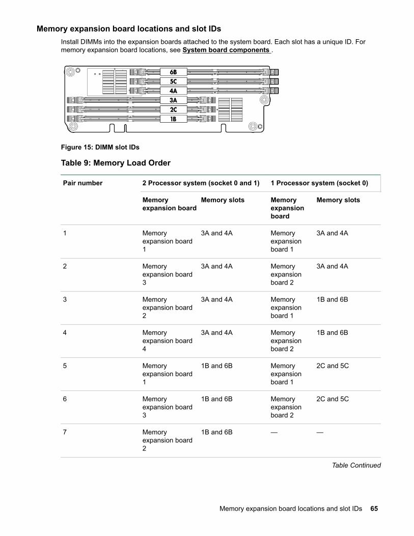
Memory expansion board locations and slot IDsInstall DIMMs into the expansion boards attached to the system board. Each slot has a unique ID. Formemory expansion board locations, see System board components .
Figure 15: DIMM slot IDs
Table 9: Memory Load Order
Pair number 2 Processor system (socket 0 and 1) 1 Processor system (socket 0)
Memoryexpansion board
Memory slots Memoryexpansionboard
Memory slots
1 Memoryexpansion board1
3A and 4A Memoryexpansionboard 1
3A and 4A
2 Memoryexpansion board3
3A and 4A Memoryexpansionboard 2
3A and 4A
3 Memoryexpansion board2
3A and 4A Memoryexpansionboard 1
1B and 6B
4 Memoryexpansion board4
3A and 4A Memoryexpansionboard 2
1B and 6B
5 Memoryexpansion board1
1B and 6B Memoryexpansionboard 1
2C and 5C
6 Memoryexpansion board3
1B and 6B Memoryexpansionboard 2
2C and 5C
7 Memoryexpansion board2
1B and 6B — —
Table Continued
Memory expansion board locations and slot IDs 65
Pair number 2 Processor system (socket 0 and 1) 1 Processor system (socket 0)
Memoryexpansion board
Memory slots Memoryexpansionboard
Memory slots
8 Memoryexpansion board4
1B and 6B — —
9 Memoryexpansion board1
2C and 5C — —
10 Memoryexpansion board3
2C and 5C — —
11 Memoryexpansion board2
2C and 5C — —
12 Memoryexpansion board4
2C and 5C — —
TIP:
You can load DIMM pairs on a single expansion board at a time, but this option reduces systemperformance.
Memory loading rules and guidelines
• CAUTION:
Failure to observe the following cautions results in system degradation or failure:
• Only ECC DIMMs are supported.
• Load DIMM pairs from largest to smallest capacity. For example, if you have a pair of 4 GB DIMMsand a pair of 2 GB DIMMs, install the pair of 4 GB DIMMs first.
NOTE:
Faster DIMMs and slower DIMMs can be installed on different slots within the same channel, butfaster DIMMs operate at the timing of the slowest DIMM populated.
• Alternate loading between installed processors. Do not install DIMMs if the corresponding processor isnot installed.
• Spread DIMMs evenly between processors.
• Load DIMMs in pairs by increasing letter.
• For best performance, install DIMM pairs in the specified sequence shown in Memory Load Order.DIMMs can be loaded in an economic order, for example, loading the first expansion board full before
66 Memory loading rules and guidelines
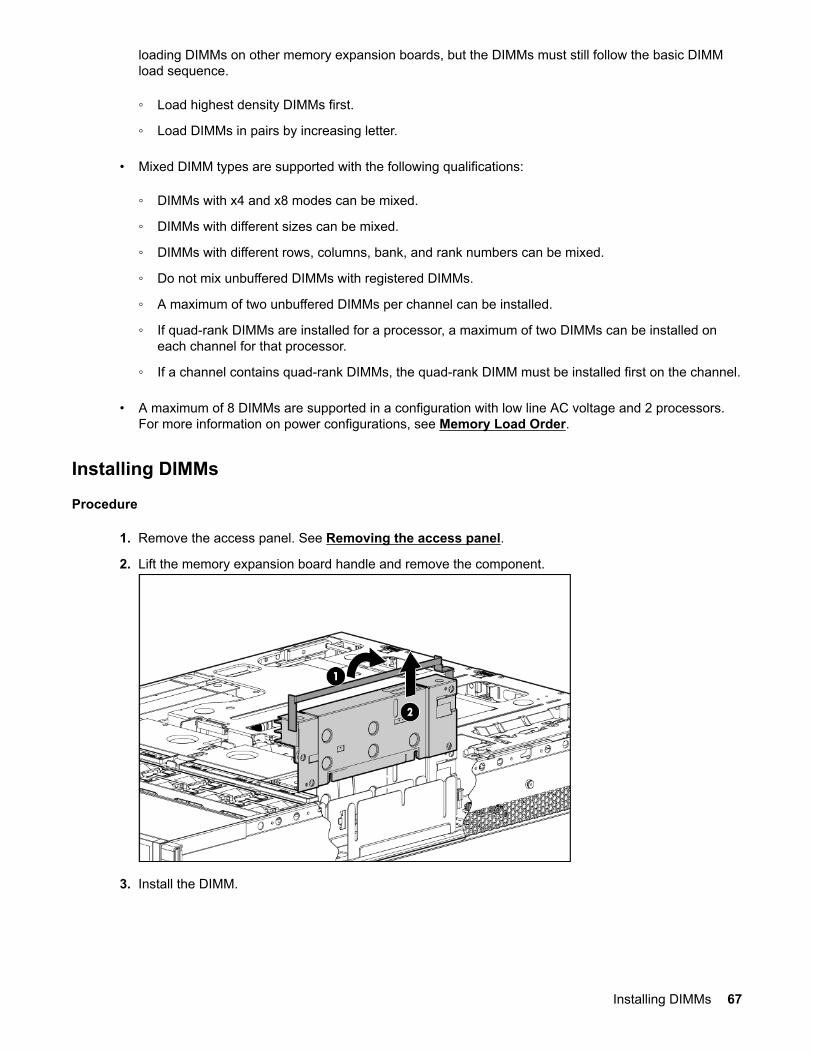
loading DIMMs on other memory expansion boards, but the DIMMs must still follow the basic DIMMload sequence.
◦ Load highest density DIMMs first.
◦ Load DIMMs in pairs by increasing letter.
• Mixed DIMM types are supported with the following qualifications:
◦ DIMMs with x4 and x8 modes can be mixed.
◦ DIMMs with different sizes can be mixed.
◦ DIMMs with different rows, columns, bank, and rank numbers can be mixed.
◦ Do not mix unbuffered DIMMs with registered DIMMs.
◦ A maximum of two unbuffered DIMMs per channel can be installed.
◦ If quad-rank DIMMs are installed for a processor, a maximum of two DIMMs can be installed oneach channel for that processor.
◦ If a channel contains quad-rank DIMMs, the quad-rank DIMM must be installed first on the channel.
• A maximum of 8 DIMMs are supported in a configuration with low line AC voltage and 2 processors.For more information on power configurations, see Memory Load Order.
Installing DIMMs
Procedure
1. Remove the access panel. See Removing the access panel.
2. Lift the memory expansion board handle and remove the component.
3. Install the DIMM.
Installing DIMMs 67
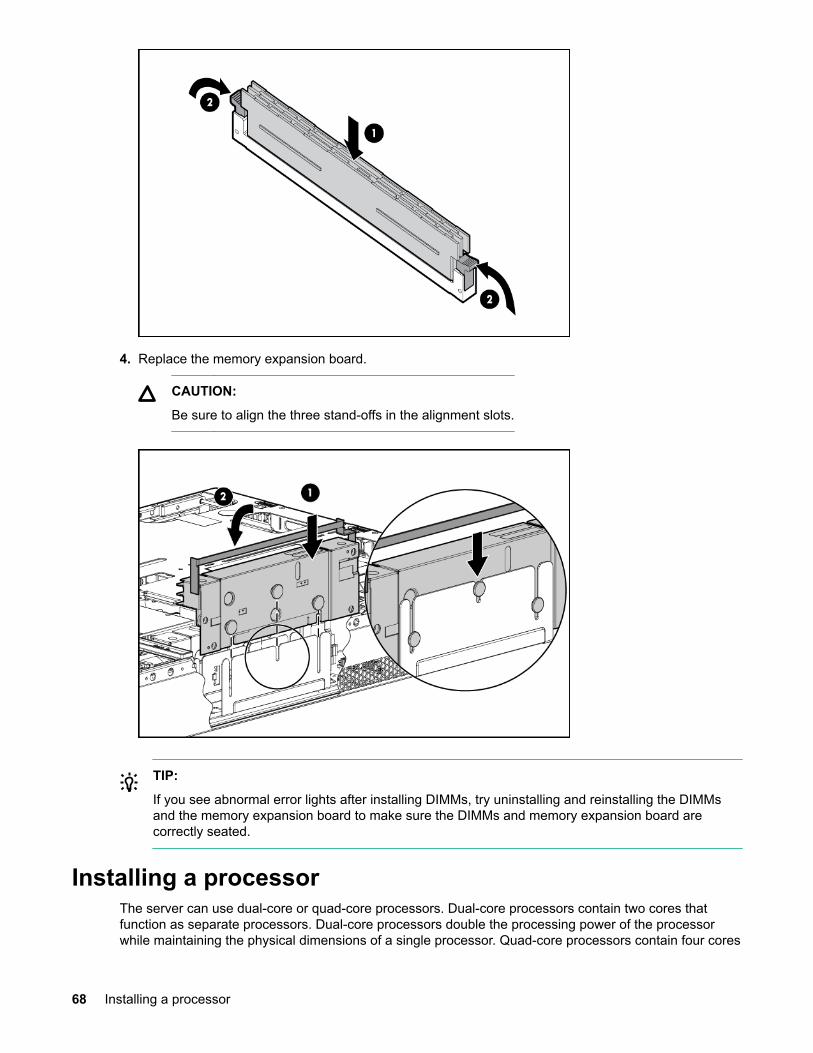
4. Replace the memory expansion board.
CAUTION:
Be sure to align the three stand-offs in the alignment slots.
TIP:
If you see abnormal error lights after installing DIMMs, try uninstalling and reinstalling the DIMMsand the memory expansion board to make sure the DIMMs and memory expansion board arecorrectly seated.
Installing a processorThe server can use dual-core or quad-core processors. Dual-core processors contain two cores thatfunction as separate processors. Dual-core processors double the processing power of the processorwhile maintaining the physical dimensions of a single processor. Quad-core processors contain four cores
68 Installing a processor
that function as separate processors. Quad-core processors quadruple the processing power of theprocessor while maintaining the physical dimensions of a single processor.
The server holds one or two dual or quad-core processors that provide the following configurationoptions:
Dual-core processors:
• 1P/2C (one processor/2 cores)
• 2P/4C
Quad-core processors:
• 1P/4C
• 2P/8C
The first processor must be installed in socket 0, and the second processor in socket 1.
CAUTION:
Intel quad-core processors cannot be intermixed with similar dual-core processors. Processor speedand cache size must be identical for all processors in a server. To ensure compatibility, whetherupgrading, replacing, or adding an additional processor, use processors with identical part numbers.
Failure to observe this caution results in performance degradation or server failure.
CAUTION:
Observe all ESD safety precautions before attempting this procedure. Failure to follow ESD safetyprecautions can result in damage to the server.
Processor load orderThe server holds up to two dual-core or quad-core processors on the system board. The sockets on thesystem board are labeled Module 0 and Module 1. If the server has only one processor, it is installed insocket 0. Install the second processor in socket 1.
See Processor load order for the processor socket numbers.
Table 10: Processor load order
Processor Socket
0 Module 0
1 Module 1
Installing a processor and heat sink module
CAUTION:
The pins on the processor socket are very fragile. Any damage to them might require replacing thesystem board.
Processor load order 69
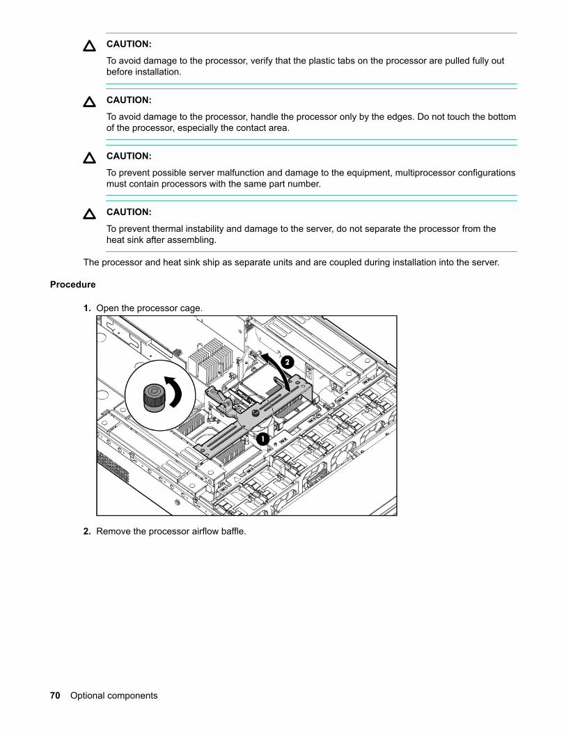
CAUTION:
To avoid damage to the processor, verify that the plastic tabs on the processor are pulled fully outbefore installation.
CAUTION:
To avoid damage to the processor, handle the processor only by the edges. Do not touch the bottomof the processor, especially the contact area.
CAUTION:
To prevent possible server malfunction and damage to the equipment, multiprocessor configurationsmust contain processors with the same part number.
CAUTION:
To prevent thermal instability and damage to the server, do not separate the processor from theheat sink after assembling.
The processor and heat sink ship as separate units and are coupled during installation into the server.
Procedure
1. Open the processor cage.
2. Remove the processor airflow baffle.
70 Optional components
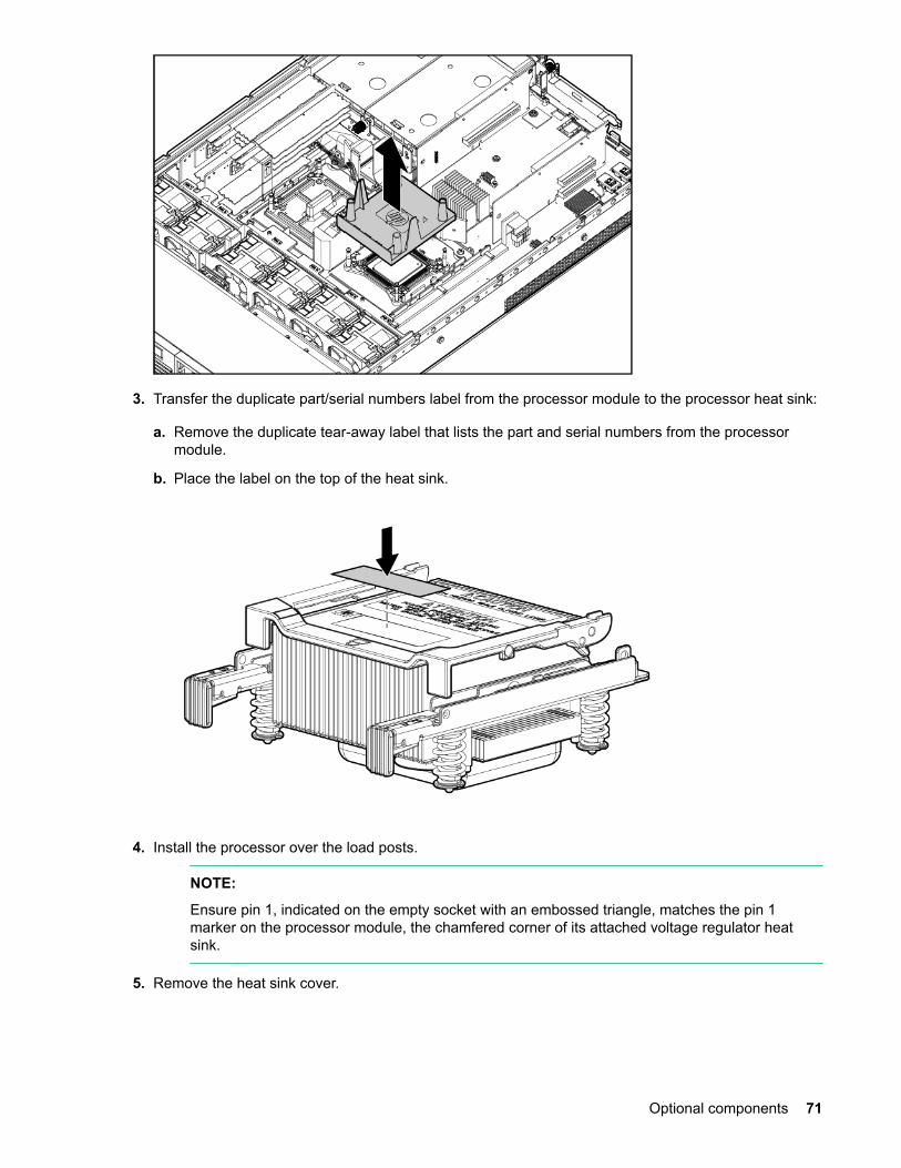
3. Transfer the duplicate part/serial numbers label from the processor module to the processor heat sink:
a. Remove the duplicate tear-away label that lists the part and serial numbers from the processormodule.
b. Place the label on the top of the heat sink.
4. Install the processor over the load posts.
NOTE:
Ensure pin 1, indicated on the empty socket with an embossed triangle, matches the pin 1marker on the processor module, the chamfered corner of its attached voltage regulator heatsink.
5. Remove the heat sink cover.
Optional components 71
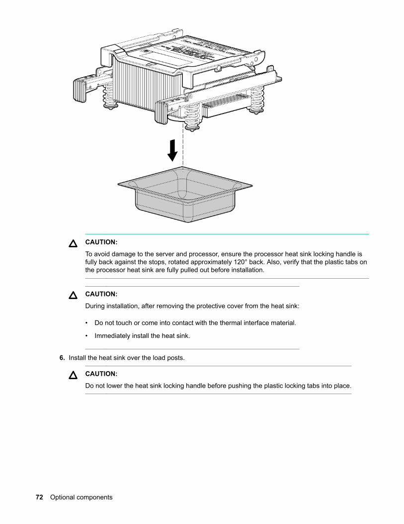
CAUTION:
To avoid damage to the server and processor, ensure the processor heat sink locking handle isfully back against the stops, rotated approximately 120° back. Also, verify that the plastic tabs onthe processor heat sink are fully pulled out before installation.
CAUTION:
During installation, after removing the protective cover from the heat sink:
• Do not touch or come into contact with the thermal interface material.
• Immediately install the heat sink.
6. Install the heat sink over the load posts.
CAUTION:
Do not lower the heat sink locking handle before pushing the plastic locking tabs into place.
72 Optional components

CAUTION:
To prevent thermal instability and damage to the server, do not separate the processor modulefrom the processor heat sink after they have been coupled.
NOTE:
Positive engagement clicking must occur during engaging of the processor heat sink andprocessor module onto the socket to ensure proper seating.
7. Secure the heat sink to the processor.
a. Slide both plastic locking tabs into place. See callout 1 in the following figure.
b. Flip the latch down. See callout 2 in the following figure.
CAUTION:
To prevent thermal instability and damage to the server, do not separate the processormodule from the processor heat sink after they have been coupled.
Optional components 73
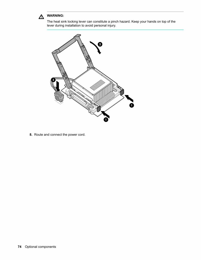
WARNING:
The heat sink locking lever can constitute a pinch hazard. Keep your hands on top of thelever during installation to avoid personal injury.
8. Route and connect the power cord.
74 Optional components

9. Tie wrap the processor cable to the right tie point on the processor assembly.
CAUTION:
When the processor is installed, dress all slack in the power cable to the connector end of thecable. Failure to do so can result in pinched or damaged processor power cables.
NOTE:
If you are adding an additional processor to your server, the DIMMs in the server must bereconfigured to support both processors. For more information, see Memory configurations onpage 64.
HPE Trusted Platform Module (TPM)The TPM is not a customer-serviceable part.
HPE Trusted Platform Module (TPM) 75

CAUTION:
Any attempt to remove an installed TPM from the system board breaks or disfigures the TPMsecurity rivet. Upon locating a broken or disfigured rivet on an installed TPM, administrators shouldconsider the system compromised and take appropriate measures to ensure the integrity of thesystem data.
If you suspect a TPM board failure, leave the TPM installed and remove the system board (Removingand replacing the system board on page 171). Contact a Hewlett Packard Enterprise authorizedservice provider for a replacement system board and TPM board.
Installing a Trusted Platform Module (TPM) and TPM security rivetThe TPM is an optional security component which enhances security capabilities for the server runningthe HP-UX operating system. The TPM is a security chip that is unique to the server. It performs keysecurity processes independent of other hardware components. The TPM creates and stores additionalencryption keys from the root key of the system. The encryption keys created by the TPM encapsulatesystem application encryption keys to provide an additional layer of security for sensitive system data.
TPM installation requires the use of drive encryption technology.
WARNING:
Once the TPM is installed on your system board, it cannot be removed. If the TPM fails, the systemboard needs to be replaced. Attempting to remove the TPM from the system board will void anyexisting Hewlett Packard Enterprise service contract and cause the server to fail.
WARNING:
To reduce the risk of personal injury, electric shock, or damage to the equipment, remove the powercord to remove power from the server. The front panel Power On/Standby button does notcompletely shut off system power. Portions of the power supply and some internal circuitry remainactive until AC power is removed.
CAUTION:
Always observe the guidelines in this document. Failure to follow these guidelines can causehardware damage or halt data access.
When installing a TPM, observe the following guidelines:
Procedure
1. Always enable the TPM and ensure that the TPM is recognized by the system before installing theTPM security rivet.
2. When installing or replacing hardware, Hewlett Packard Enterprise service providers cannot enablethe TPM or the encryption technology. For security reasons, only the customer can enable thesefeatures.
3. When returning a system board for service replacement, do not remove the TPM from the systemboard. When requested, Hewlett Packard Enterprise Service will provide a TPM with the spare systemboard.
4. Any attempt to remove an installed TPM from the system board breaks or disfigures the TPM securityrivet. Upon locating a broken or disfigured rivet on an installed TPM, consider the systemcompromised and take appropriate measures to ensure the integrity of the system data.
76 Installing a Trusted Platform Module (TPM) and TPM security rivet
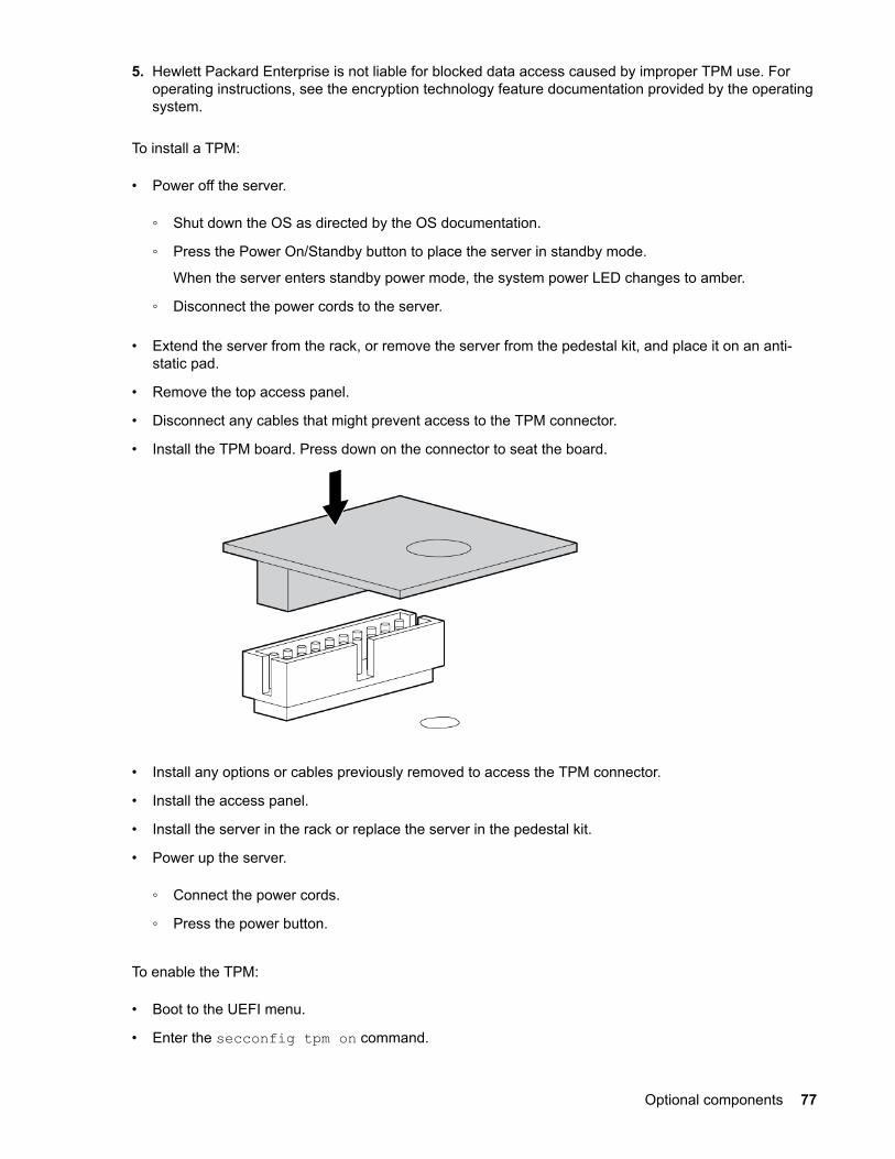
5. Hewlett Packard Enterprise is not liable for blocked data access caused by improper TPM use. Foroperating instructions, see the encryption technology feature documentation provided by the operatingsystem.
To install a TPM:
• Power off the server.
◦ Shut down the OS as directed by the OS documentation.
◦ Press the Power On/Standby button to place the server in standby mode.
When the server enters standby power mode, the system power LED changes to amber.
◦ Disconnect the power cords to the server.
• Extend the server from the rack, or remove the server from the pedestal kit, and place it on an anti-static pad.
• Remove the top access panel.
• Disconnect any cables that might prevent access to the TPM connector.
• Install the TPM board. Press down on the connector to seat the board.
• Install any options or cables previously removed to access the TPM connector.
• Install the access panel.
• Install the server in the rack or replace the server in the pedestal kit.
• Power up the server.
◦ Connect the power cords.
◦ Press the power button.
To enable the TPM:
• Boot to the UEFI menu.
• Enter the secconfig tpm on command.
Optional components 77

• Enter the reset command. The system will reboot and the TPM is enabled.
• When the system has rebooted, enter the command secconfig tpm, to verify the TPM is enabled.
• Enable the TPM in the OS. For OS-specific instructions, see the OS documentation.
For more information on firmware updates and hardware procedures, see the HPE Trusted PlatformModule Best Practices White Paper on the Hewlett Packard Enterprise website: http://www.hpe.com/support.
To install the TPM security rivet:
CAUTION:
Always enable the TPM and ensure that the TPM is recognized by the system before installing thesecurity rivet. Removing the TPM security rivet after it is secured to the system board can causedamage to the TPM security rivet, the TPM, and the system board.
• Power off the server.
◦ Shut down the OS as directed by the OS documentation.
◦ Press the Power On/Standby button to place the server in standby mode. When the server entersstandby power mode, the server power LED changes to amber.
◦ Disconnect the power cords.
• Extend the server from the rack, or remove the server from the pedestal kit.
• Place the server on a flat, level work surface.
• Remove the access panel.
• Remove any cables that might prevent access to the TPM connector.
• Install the TPM security rivet by pressing the rivet firmly into the system board.
• Install any cables previously removed to access the TPM.
• Install the top access panel.
78 Optional components

• Install the server into the rack.
• Power up the server.
Verifying installed components in the serverUse the following procedure to verify that the components you have installed into the server arerecognized by the server:
Procedure
1. Press S to enter the UEFI shell.
2. Wait for the UEFI Shell prompt to appear.
3. Enter info all from the UEFI Shell prompt. The following appears:
NOTE:
Your display might not match the display shown.
4.
info all
SYSTEM INFORMATION
Date/Time: Oct 14, 2010 19:27:21 (20:10:14:19:27:21)Timezone: GMT+00:00DST: Not Affected
Manufacturer: hpProduct Name: Integrity rx2800 i2Product Number: AH395ASerial Number: SGH010XTFWUUID: 136EE0A3-5481-11DF-AA77-FAE232322A00Physical Serial Number: SGH010XTFWPhysical UUID: 136EE0A3-5481-11DF-AA77-FAE232322A00
CPU INFORMATION
Active Core Cores/ L3 Family/ CPU Logical Cache Model CPU Socket CPUs Speed Size (hex.) Rev State ------ ------- -------- ------ ------ ----- ------------ 0 4/8 1.6 GHz 5 MB 20/02 E0 Active 1 4/8 1.6 GHz 5 MB 20/02 E0 Active
CPU threads are turned on.Total Active Logical CPUs : 16
BOOT CPU INFORMATION
CPU Socket/ Core ----------- 0/0
Verifying installed components in the server 79
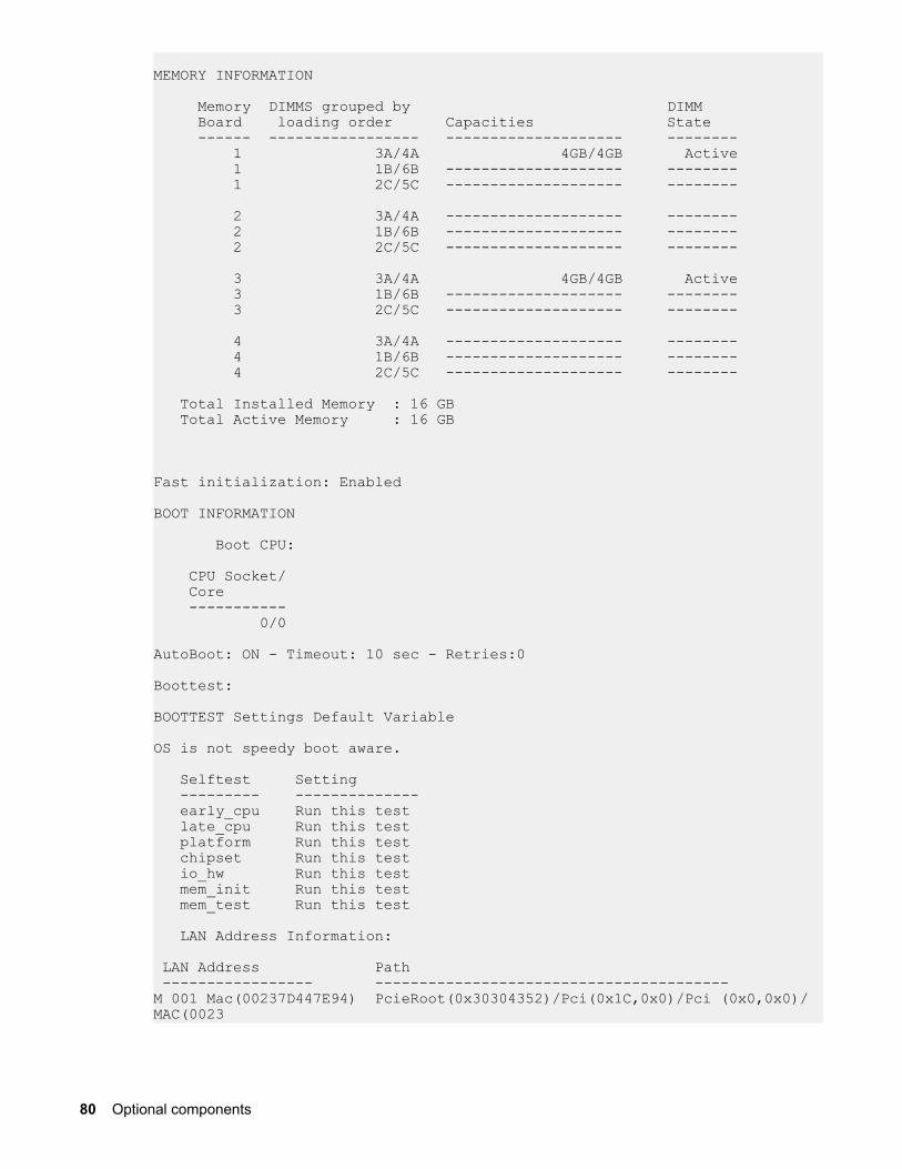
MEMORY INFORMATION
Memory DIMMS grouped by DIMM Board loading order Capacities State ------ ----------------- -------------------- -------- 1 3A/4A 4GB/4GB Active 1 1B/6B -------------------- -------- 1 2C/5C -------------------- --------
2 3A/4A -------------------- -------- 2 1B/6B -------------------- -------- 2 2C/5C -------------------- --------
3 3A/4A 4GB/4GB Active 3 1B/6B -------------------- -------- 3 2C/5C -------------------- --------
4 3A/4A -------------------- -------- 4 1B/6B -------------------- -------- 4 2C/5C -------------------- --------
Total Installed Memory : 16 GB Total Active Memory : 16 GB
Fast initialization: Enabled
BOOT INFORMATION
Boot CPU:
CPU Socket/ Core ----------- 0/0
AutoBoot: ON - Timeout: 10 sec - Retries:0
Boottest:
BOOTTEST Settings Default Variable
OS is not speedy boot aware.
Selftest Setting --------- -------------- early_cpu Run this test late_cpu Run this test platform Run this test chipset Run this test io_hw Run this test mem_init Run this test mem_test Run this test
LAN Address Information:
LAN Address Path ----------------- ----------------------------------------M 001 Mac(00237D447E94) PcieRoot(0x30304352)/Pci(0x1C,0x0)/Pci (0x0,0x0)/MAC(0023
80 Optional components
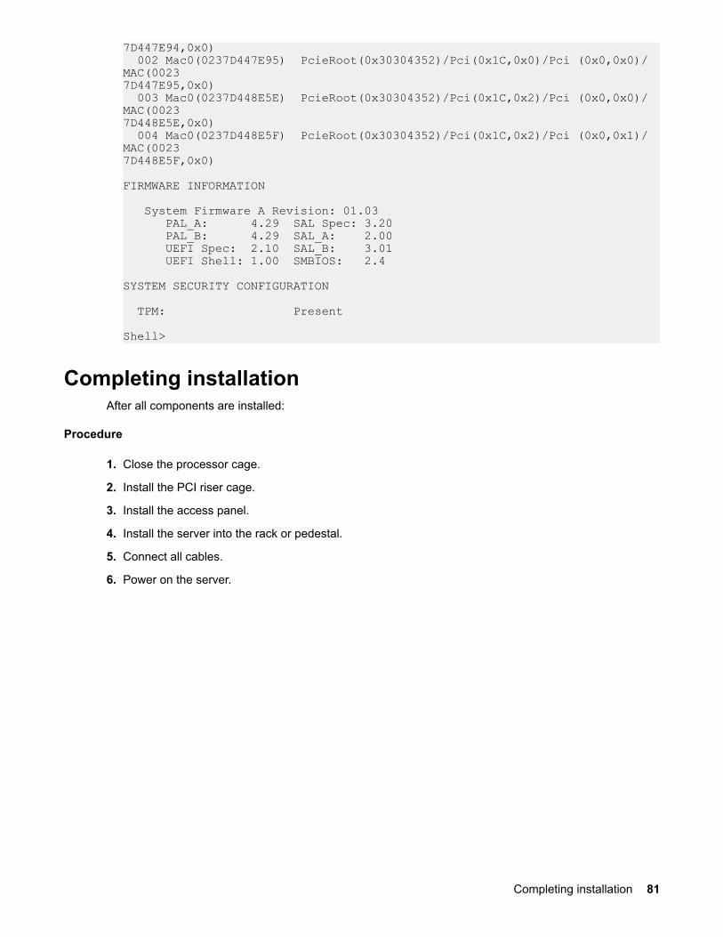
7D447E94,0x0) 002 Mac0(0237D447E95) PcieRoot(0x30304352)/Pci(0x1C,0x0)/Pci (0x0,0x0)/MAC(00237D447E95,0x0) 003 Mac0(0237D448E5E) PcieRoot(0x30304352)/Pci(0x1C,0x2)/Pci (0x0,0x0)/MAC(00237D448E5E,0x0) 004 Mac0(0237D448E5F) PcieRoot(0x30304352)/Pci(0x1C,0x2)/Pci (0x0,0x1)/MAC(00237D448E5F,0x0)
FIRMWARE INFORMATION
System Firmware A Revision: 01.03 PAL_A: 4.29 SAL Spec: 3.20 PAL_B: 4.29 SAL_A: 2.00 UEFI Spec: 2.10 SAL_B: 3.01 UEFI Shell: 1.00 SMBIOS: 2.4
SYSTEM SECURITY CONFIGURATION TPM: Present
Shell>
Completing installationAfter all components are installed:
Procedure
1. Close the processor cage.
2. Install the PCI riser cage.
3. Install the access panel.
4. Install the server into the rack or pedestal.
5. Connect all cables.
6. Power on the server.
Completing installation 81
TroubleshootingCause
The purpose of this chapter is to provide a preferred methodology (strategies and procedures) and toolsfor troubleshooting the server error and fault conditions.
How to contact Hewlett Packard EnterpriseFor information on how to contact Hewlett Packard Enterprise, see Accessing Hewlett PackardEnterprise Support.
Methodology
General troubleshooting methodologyThere are multiple entry points to the troubleshooting process, dependent upon your level oftroubleshooting expertise, the tools/processes/procedures which you have at your disposal, and thenature of the system fault or failure.
Typically, you select from a set of symptoms, ranging from very simple (system LED is blinking) to themost difficult (Machine Check Abort (MCA)) has occurred. The following is a list of symptom examples:
NOTE:
Your output might differ from the output in the examples in this book depending on your server andits configuration.
• Front panel LED blinking
• System alert present on console
• System will not power-up
• System will not boot
• Error/Event Message received
• Machine Check Abort (MCA) occurred
Narrow down the observed issue to the specific troubleshooting procedure required. Isolate the failure toa specific part of the server, so you can perform more detailed troubleshooting. For example:
• Issue- Front panel LED blinking
NOTE:
The front panel health LEDs flash amber with a warning indication, or flash red with a faultindication.
◦ System Alert on console?
Analyze the alert by using the system event log (SEL) and forward progress log (FPL), to identifythe last error logged by the server. Use the iLO 3 MP commands to view the SEL and FPL, either
82 Troubleshooting
through the iLO 3 MP serial text interface, or through Secure Shell, or through the web GUI on theiLO 3 MP LAN.
You can now determine which area of the system requires further analysis. For example, if the symptomwas "system will not power-up", the initial troubleshooting procedure might indicate a issue with the DCpower rail not coming up after the power switch was turned on.
You have now reached the point where the failed CRU has been identified and needs to be replaced.Perform the specific removal and replacement procedure, and verification steps.
NOTE:
If multiple CRUs are identified as part of the solution, a fix cannot be guaranteed unless all identifiedfailed CRUs are replaced.
You might have to perform specific recovery procedures to finish the repair. For example, if the systemboard is replaced, you need to restore customer specific information.
Should a failure occur, the System Insight Display LEDs, SEL and FPL help you identify the issue orCRU:
• LEDs. The front panel LEDs and LAN LEDs of the server change color and blink to help identifyspecific issues.
• The System Event Log (SEL) provides detailed information about the errors identified by the LEDs.
• The Forward Progress Log (FPL) provides details about the boot progress of the server.
The System Insight Display LEDs are cleared after the issue is corrected or the CRU is replaced and bycycling AC power.
If the LEDs, SEL and FPL do not give you enough information to identify the issue, Hewlett PackardEnterprise also provides diagnostic tools with each operating system (see Troubleshooting tools onpage 91 for more details).
NOTE:
Always check the iLO 3 MP SEL in the case of a blinking yellow or red front panel LED, beforereplacing any hardware. The default display mode is Keyword mode. You can also view the errormessages in Text mode.
Recommended troubleshooting methodologyThe recommended methodology for troubleshooting a server error or fault is as follows:
Procedure
1. Consult the system console for any messages, emails, etc., pertaining to a server error or fault.
2. View the front panel LEDs (power, SID, and system health), either locally, or remotely through the iLO3 MP vfp command.
3. Compare the state of the server LEDs (off; flashing or steady; red, green, or amber) with the LEDstates listed in the LED Panel State Table in this section.
4. Go to the step number of the Basic Low End Troubleshooting Table, as specified in the right column ofthe LED Panel State Table, located in the row which corresponds to your front panel LED displaystate.
Recommended troubleshooting methodology 83

5. Read the symptom/condition information in the left column of the Basic Low End TroubleshootingTable.
6. Perform the actions specified in the Action column.
7. If you need more details, see the appropriate subsection of this chapter, where this information isprovided in the Action column. You might be directed to access and read one or more error logs (SELand/or FPL).
While Hewlett Packard Enterprise suggests that all users follow the recommended troubleshootingmethodology and use the Basic and Advanced Troubleshooting Tables in the next subsection, as a moreexperienced troubleshooter, you might elect to go directly to the subsection which corresponds to yourown entry point of choice.
Troubleshooting entry points provides the corresponding subsection or location title for these differententry points (for example, if you would prefer to start by examining the logs, you can go directly to thesubsection entitled Errors and reading error logs):
Table 11: Troubleshooting entry points
Entry point Subsection or location
Front panel/System Insight Display LEDs Basic and advanced troubleshooting tables on page 84and Troubleshooting tools on page 91
System Event Log and Forward ProgressLogs
Errors and reading error logs
Offline and Online Diagnostics/INITbutton
Troubleshooting tools on page 91
System Event Analyzer Troubleshooting tools on page 91 (see also http://www.compaq.com/support/svctools/webes/ for moreinformation about this tool)
Basic and advanced troubleshooting tablesThe following troubleshooting tables are designed for use by both trained and untrained supportpersonnel. The tables are the first tools used to determine the symptoms or condition of a suspect server.Be aware that the state of the front panel LEDs can be viewed locally or remotely (using the vfpcommand from the iLO 3 MP).
The tables are designed to cover troubleshooting symptoms from AC power-on up to booting theoperating system (OS), specifically in Steps 1-5. In most cases begin with Step 1 in Basic low endtroubleshooting, sequencing through the table steps to locate the symptom/condition most descriptive ofyour current server status; this becomes the first step in your troubleshooting procedure. Whereappropriate, an action or actions prescribed in the "Action" column of Basic low end troubleshooting isfollowed by a reference to the corresponding subsection of this chapter for further information.
84 Basic and advanced troubleshooting tables
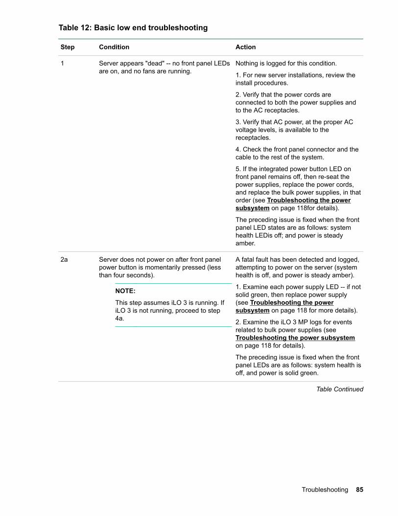
Table 12: Basic low end troubleshooting
Step Condition Action
1 Server appears "dead" -- no front panel LEDsare on, and no fans are running.
Nothing is logged for this condition.
1. For new server installations, review theinstall procedures.
2. Verify that the power cords areconnected to both the power supplies andto the AC receptacles.
3. Verify that AC power, at the proper ACvoltage levels, is available to thereceptacles.
4. Check the front panel connector and thecable to the rest of the system.
5. If the integrated power button LED onfront panel remains off, then re-seat thepower supplies, replace the power cords,and replace the bulk power supplies, in thatorder (see Troubleshooting the powersubsystem on page 118for details).
The preceding issue is fixed when the frontpanel LED states are as follows: systemhealth LEDis off; and power is steadyamber.
2a Server does not power on after front panelpower button is momentarily pressed (lessthan four seconds).
NOTE:
This step assumes iLO 3 is running. IfiLO 3 is not running, proceed to step4a.
A fatal fault has been detected and logged,attempting to power on the server (systemhealth is off, and power is steady amber).
1. Examine each power supply LED -- if notsolid green, then replace power supply(see Troubleshooting the powersubsystem on page 118 for more details).
2. Examine the iLO 3 MP logs for eventsrelated to bulk power supplies (see Troubleshooting the power subsystemon page 118 for details).
The preceding issue is fixed when the frontpanel LEDs are as follows: system health isoff, and power is solid green.
Table Continued
Troubleshooting 85

Step Condition Action
2b System health LED is flashing amber. A warning or critical failure has beendetected and logged after server powers on(system health is flashing amber, andpower is steady green). Examine eachpower supply LED. If not solid green,replace power supply (see Troubleshooting the power subsystemon page 118for details).
The preceding issue is fixed when thefailure condition is corrected, and the frontpanel LED states are as follows: systemhealth is steady green, and power is steadygreen.
3 System health LED is flashing red. A fatal fault has been detected and loggedafter attempting to power on the server(system health is flashing red, SEL is red,and power is steady green).
1. Examine each power supply LED. If notsolid green, replace power supply (see Troubleshooting the power subsystemon page 118for details).
2. Check SID LED panel to identify failed orfaulty internal CRU (see Troubleshootingtools on page 91 for details).
The preceding issue is fixed when aredundant, internal CRU is replaced, andthe front panel LED states are as follows:system health is off, SEL is off and power issteady green.
Table Continued
86 Troubleshooting
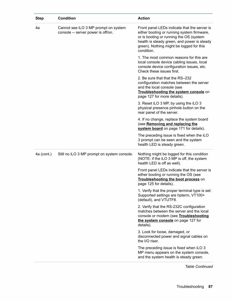
Step Condition Action
4a Cannot see iLO 3 MP prompt on systemconsole -- server power is off/on.
Front panel LEDs indicate that the server iseither booting or running system firmware,or is booting or running the OS (systemhealth is steady green, and power is steadygreen). Nothing might be logged for thiscondition.
1. The most common reasons for this arelocal console device cabling issues, localconsole device configuration issues, etc.Check these issues first.
2. Be sure that that the RS–232configuration matches between the serverand the local console (see Troubleshooting the system console onpage 127 for more details).
3. Reset iLO 3 MP, by using the iLO 3physical presence pinhole button on therear panel of the server.
4. If no change, replace the system board(see Removing and replacing thesystem board on page 171 for details).
The preceding issue is fixed when the iLO3 prompt can be seen and the systemhealth LED is steady green.
4a (cont.) Still no iLO 3 MP prompt on system console. Nothing might be logged for this condition(NOTE: if the iLO 3 MP is off, the systemhealth LED is off as well).
Front panel LEDs indicate that the server iseither booting or running the OS (see Troubleshooting the boot process onpage 125 for details).
1. Verify that the proper terminal type is set:Supported settings are hpterm, VT100+(default), and VTUTF8.
2. Verify that the RS-232C configurationmatches between the server and the localconsole or modem (see Troubleshootingthe system console on page 127 fordetails).
3. Look for loose, damaged, ordisconnected power and signal cables onthe I/O riser.
The preceding issue is fixed when iLO 3MP menu appears on the system console,and the system health is steady green.
Table Continued
Troubleshooting 87
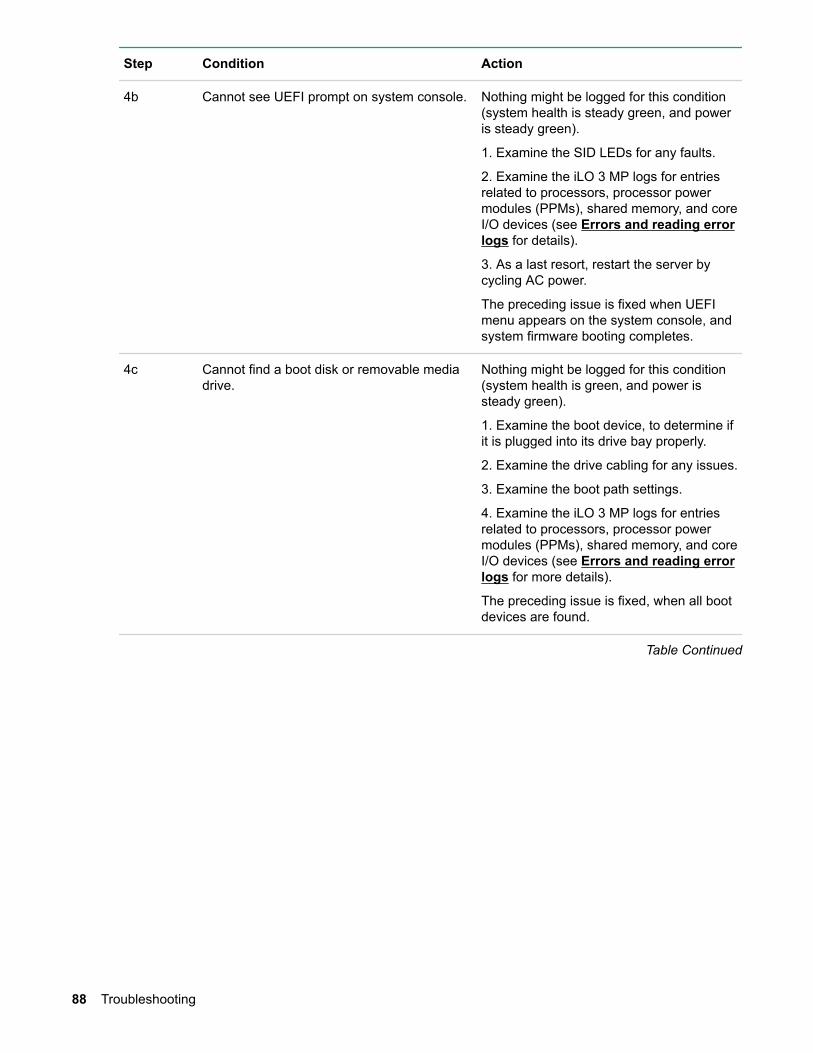
Step Condition Action
4b Cannot see UEFI prompt on system console. Nothing might be logged for this condition(system health is steady green, and poweris steady green).
1. Examine the SID LEDs for any faults.
2. Examine the iLO 3 MP logs for entriesrelated to processors, processor powermodules (PPMs), shared memory, and coreI/O devices (see Errors and reading errorlogs for details).
3. As a last resort, restart the server bycycling AC power.
The preceding issue is fixed when UEFImenu appears on the system console, andsystem firmware booting completes.
4c Cannot find a boot disk or removable mediadrive.
Nothing might be logged for this condition(system health is green, and power issteady green).
1. Examine the boot device, to determine ifit is plugged into its drive bay properly.
2. Examine the drive cabling for any issues.
3. Examine the boot path settings.
4. Examine the iLO 3 MP logs for entriesrelated to processors, processor powermodules (PPMs), shared memory, and coreI/O devices (see Errors and reading errorlogs for more details).
The preceding issue is fixed, when all bootdevices are found.
Table Continued
88 Troubleshooting
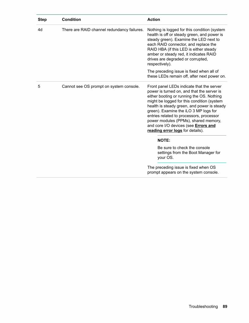
Step Condition Action
4d There are RAID channel redundancy failures. Nothing is logged for this condition (systemhealth is off or steady green, and power issteady green). Examine the LED next toeach RAID connector, and replace theRAID HBA (if this LED is either steadyamber or steady red, it indicates RAIDdrives are degraded or corrupted,respectively).
The preceding issue is fixed when all ofthese LEDs remain off, after next power on.
5 Cannot see OS prompt on system console. Front panel LEDs indicate that the serverpower is turned on, and that the server iseither booting or running the OS. Nothingmight be logged for this condition (systemhealth is steady green, and power is steadygreen). Examine the iLO 3 MP logs forentries related to processors, processorpower modules (PPMs), shared memory,and core I/O devices (see Errors andreading error logs for details).
NOTE:
Be sure to check the consolesettings from the Boot Manager foryour OS.
The preceding issue is fixed when OSprompt appears on the system console.
Troubleshooting 89
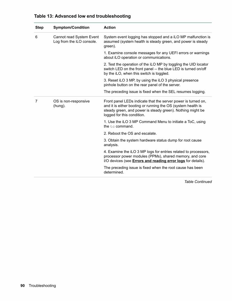
Table 13: Advanced low end troubleshooting
Step Symptom/Condition Action
6 Cannot read System EventLog from the iLO console.
System event logging has stopped and a iLO MP malfunction isassumed (system health is steady green, and power is steadygreen).
1. Examine console messages for any UEFI errors or warningsabout iLO operation or communications.
2. Test the operation of the iLO MP by toggling the UID locatorswitch LED on the front panel -- the blue LED is turned on/offby the iLO, when this switch is toggled.
3. Reset iLO 3 MP, by using the iLO 3 physical presencepinhole button on the rear panel of the server.
The preceding issue is fixed when the SEL resumes logging.
7 OS is non-responsive(hung).
Front panel LEDs indicate that the server power is turned on,and it is either booting or running the OS (system health issteady green, and power is steady green). Nothing might belogged for this condition.
1. Use the iLO 3 MP Command Menu to initiate a ToC, usingthe tc command.
2. Reboot the OS and escalate.
3. Obtain the system hardware status dump for root causeanalysis.
4. Examine the iLO 3 MP logs for entries related to processors,processor power modules (PPMs), shared memory, and coreI/O devices (see Errors and reading error logs for details).
The preceding issue is fixed when the root cause has beendetermined.
Table Continued
90 Troubleshooting
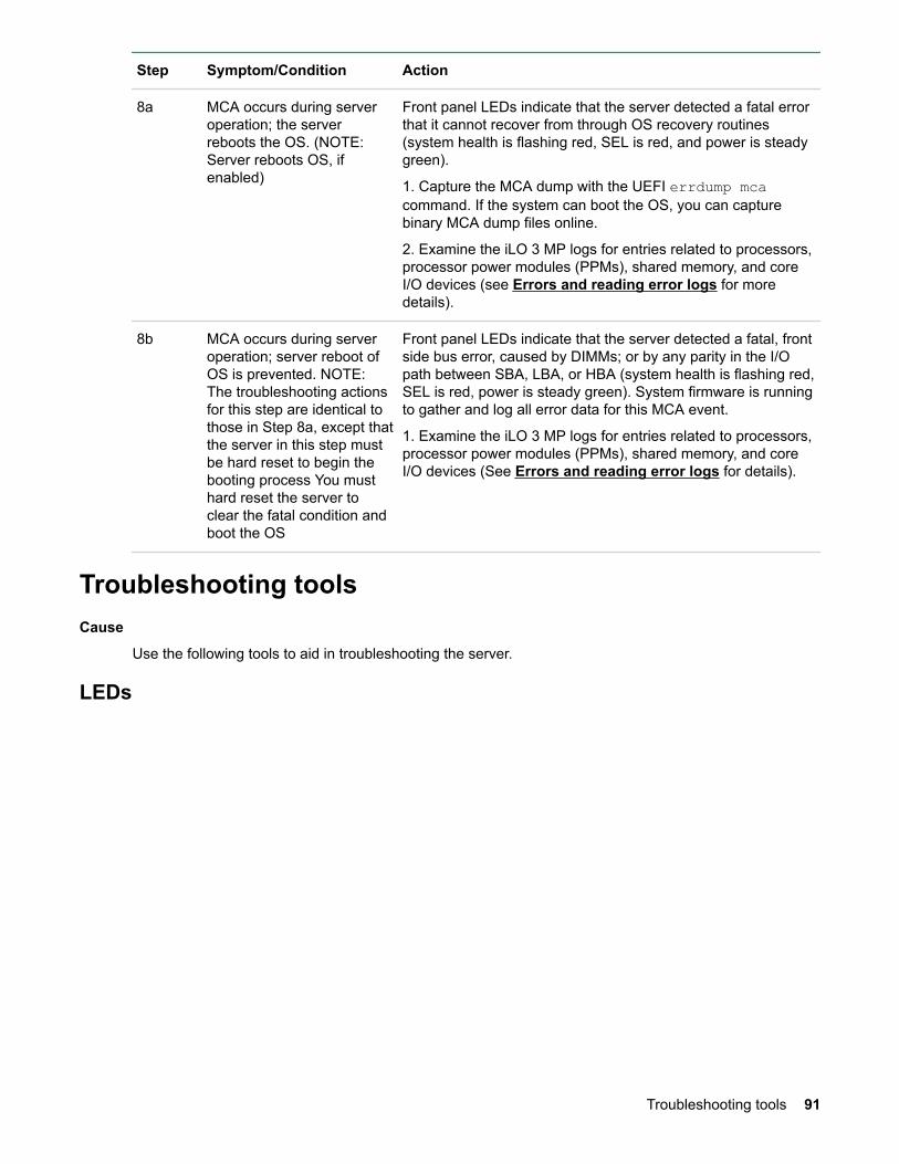
Step Symptom/Condition Action
8a MCA occurs during serveroperation; the serverreboots the OS. (NOTE:Server reboots OS, ifenabled)
Front panel LEDs indicate that the server detected a fatal errorthat it cannot recover from through OS recovery routines(system health is flashing red, SEL is red, and power is steadygreen).
1. Capture the MCA dump with the UEFI errdump mcacommand. If the system can boot the OS, you can capturebinary MCA dump files online.
2. Examine the iLO 3 MP logs for entries related to processors,processor power modules (PPMs), shared memory, and coreI/O devices (see Errors and reading error logs for moredetails).
8b MCA occurs during serveroperation; server reboot ofOS is prevented. NOTE:The troubleshooting actionsfor this step are identical tothose in Step 8a, except thatthe server in this step mustbe hard reset to begin thebooting process You musthard reset the server toclear the fatal condition andboot the OS
Front panel LEDs indicate that the server detected a fatal, frontside bus error, caused by DIMMs; or by any parity in the I/Opath between SBA, LBA, or HBA (system health is flashing red,SEL is red, power is steady green). System firmware is runningto gather and log all error data for this MCA event.
1. Examine the iLO 3 MP logs for entries related to processors,processor power modules (PPMs), shared memory, and coreI/O devices (See Errors and reading error logs for details).
Troubleshooting toolsCause
Use the following tools to aid in troubleshooting the server.
LEDs
Troubleshooting tools 91

Front panel LEDs
Table 14: Front panel controls
Name Function Status
UID button This button helps locate a particular serverwithin a rack of servers. You can remotelyactivate this function through various systemutilities.
• Blue = Identification
• Flashing blue = Remote iLO session or afirmware flash update is in progress
• Off = Off
Systemhealth LED
This LED provides information about thesystem status. • Green = Health good on all internal FRUs
and system firmware has passed"BOOT_START"
• Flashing Amber = A FRU or subsystemhas failed, or a fatal fault has occurred(system is on or in standby mode).
• Flashing Red = A fatal fault has beendetected and a FRU or subsystem hasfailed. View the SID, other LEDs, and thelogs for information.
• Off = Health good on all internal FRUsand system off
NOTE:
The System Health LED does notchange status if AC power is removedfrom a single power supply in arx2800 i2 server system with powerredundancy.
Powerbutton
This button manually powers the server onand off. • Green = System on
• Amber = System is powered off, butstandby power is on
• Off = System power and standby poweris off
The front panel of the system contains the power button/system power LED, health LED, System EventLog LED, and locator switch/LED. The server use flashing states (for example, flashing amber or red) onthese LEDs to indicate a warning or an error.
There are a total of three LEDs, arranged vertically, with the UID button and the power button each havingan integrated LED. In addition to the two integrated button/LEDs, there is a health LED.
92 Front panel LEDs
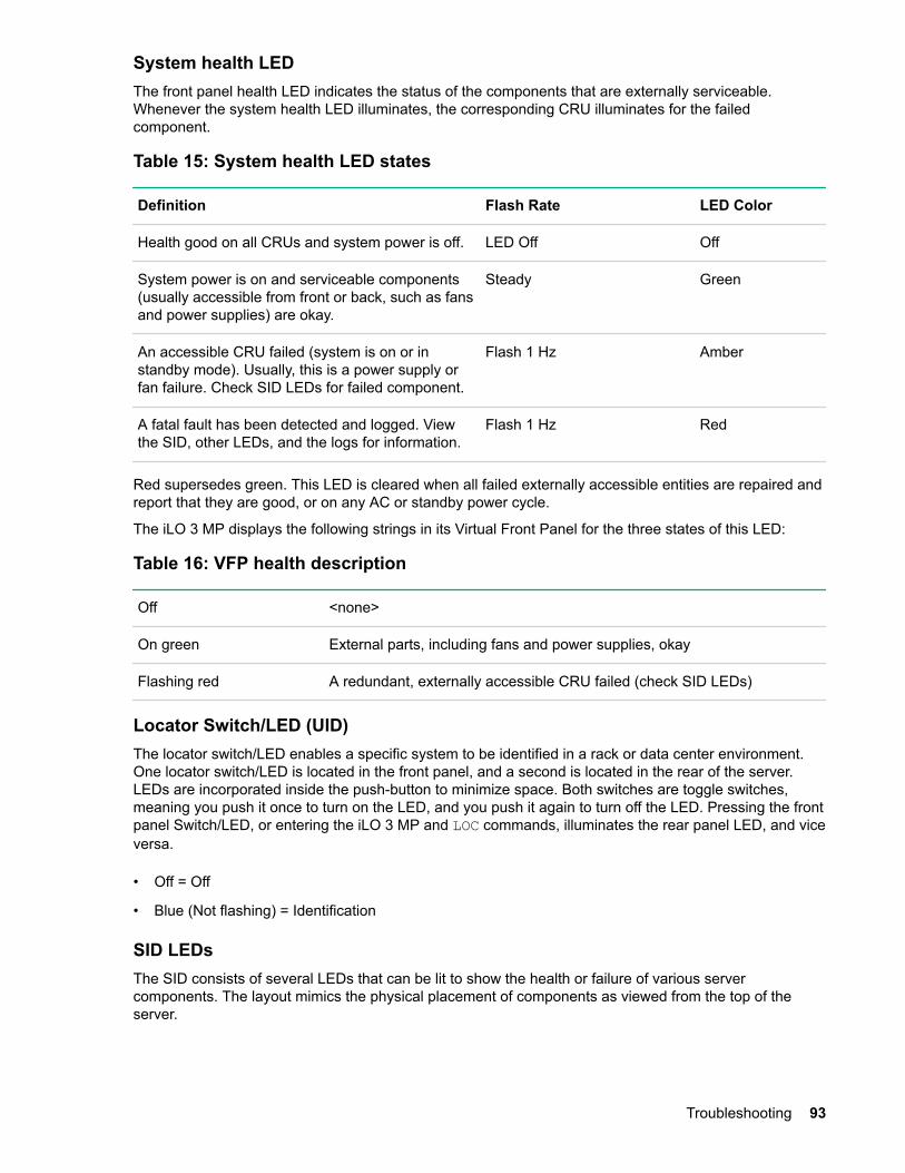
System health LEDThe front panel health LED indicates the status of the components that are externally serviceable.Whenever the system health LED illuminates, the corresponding CRU illuminates for the failedcomponent.
Table 15: System health LED states
Definition Flash Rate LED Color
Health good on all CRUs and system power is off. LED Off Off
System power is on and serviceable components(usually accessible from front or back, such as fansand power supplies) are okay.
Steady Green
An accessible CRU failed (system is on or instandby mode). Usually, this is a power supply orfan failure. Check SID LEDs for failed component.
Flash 1 Hz Amber
A fatal fault has been detected and logged. Viewthe SID, other LEDs, and the logs for information.
Flash 1 Hz Red
Red supersedes green. This LED is cleared when all failed externally accessible entities are repaired andreport that they are good, or on any AC or standby power cycle.
The iLO 3 MP displays the following strings in its Virtual Front Panel for the three states of this LED:
Table 16: VFP health description
Off <none>
On green External parts, including fans and power supplies, okay
Flashing red A redundant, externally accessible CRU failed (check SID LEDs)
Locator Switch/LED (UID)The locator switch/LED enables a specific system to be identified in a rack or data center environment.One locator switch/LED is located in the front panel, and a second is located in the rear of the server.LEDs are incorporated inside the push-button to minimize space. Both switches are toggle switches,meaning you push it once to turn on the LED, and you push it again to turn off the LED. Pressing the frontpanel Switch/LED, or entering the iLO 3 MP and LOC commands, illuminates the rear panel LED, and viceversa.
• Off = Off
• Blue (Not flashing) = Identification
SID LEDsThe SID consists of several LEDs that can be lit to show the health or failure of various servercomponents. The layout mimics the physical placement of components as viewed from the top of theserver.
Troubleshooting 93

Figure 16: System Insight Display LEDs
Table 17: SAS disk drive LEDs: RAID mode
LED State
NICs• Off = No link to network
• Flashing green = Network link and activity
• Green = Network link
Power Cap Capping Power LED
On On Green
On Off Off
Off On Off
Off Off Off
NOTE:
Power capping operation can be observedthrough iLO 3 also. For more information,see the HPE Integrity iLO 3 OperationsGuide.
94 Troubleshooting
LED State
Over Temp• Off = Server temperature good
• Amber = Server temperature too high, attentionrequired
System Event Log• Green = Normal
• Red = System fatal
Component LEDs• Off = Component health is assumed good
• Amber = Component health last known to bebad
NOTE:
The Power Supply LED is lit only when afailure or fault is detected in a power supply.Loss of AC power to a power supplygenerates a SEL entry, but does not result inthe Power Supply LED becoming lit.
Table 18: SAS disk drive LEDs : HBA mode
Drive activity LED status Drive status LEDstatus
Indication
Off, or flashing Alternating amberand blue
The drive has failed, or a predictive failure alert hasbeen received for this drive; it also has beenselected by a management application.
Off, or flashing Blue The drive is operating normally, and it has beenselected by a management application.
Flashing irregularly Regularly flashingamber(1 Hz)
The drive is active, but a predictive failure alert hasbeen received for this drive. Replace the drive assoon as possible.
Flashing irregularly Off The drive is active, and it is operating normally.
Off Amber A critical fault condition has been identified for thisdrive. Replace the drive as soon as possible.
Off Regularly flashingamber(1 Hz)
A predictive failure alert has been received for thisdrive. Replace the drive as soon as possible.
Off Off The drive is online.
Off Off Normal operation; no activity
Troubleshooting 95
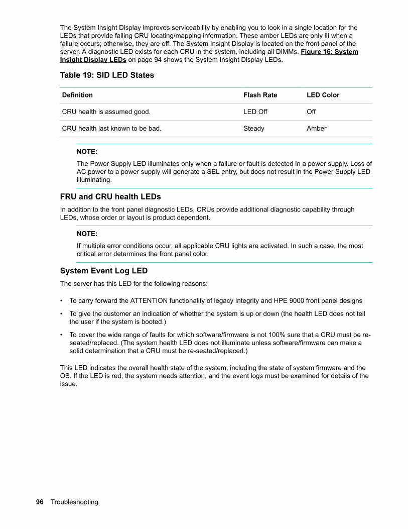
The System Insight Display improves serviceability by enabling you to look in a single location for theLEDs that provide failing CRU locating/mapping information. These amber LEDs are only lit when afailure occurs; otherwise, they are off. The System Insight Display is located on the front panel of theserver. A diagnostic LED exists for each CRU in the system, including all DIMMs. Figure 16: SystemInsight Display LEDs on page 94 shows the System Insight Display LEDs.
Table 19: SID LED States
Definition Flash Rate LED Color
CRU health is assumed good. LED Off Off
CRU health last known to be bad. Steady Amber
NOTE:
The Power Supply LED illuminates only when a failure or fault is detected in a power supply. Loss ofAC power to a power supply will generate a SEL entry, but does not result in the Power Supply LEDilluminating.
FRU and CRU health LEDsIn addition to the front panel diagnostic LEDs, CRUs provide additional diagnostic capability throughLEDs, whose order or layout is product dependent.
NOTE:
If multiple error conditions occur, all applicable CRU lights are activated. In such a case, the mostcritical error determines the front panel color.
System Event Log LEDThe server has this LED for the following reasons:
• To carry forward the ATTENTION functionality of legacy Integrity and HPE 9000 front panel designs
• To give the customer an indication of whether the system is up or down (the health LED does not tellthe user if the system is booted.)
• To cover the wide range of faults for which software/firmware is not 100% sure that a CRU must be re-seated/replaced. (The system health LED does not illuminate unless software/firmware can make asolid determination that a CRU must be re-seated/replaced.)
This LED indicates the overall health state of the system, including the state of system firmware and theOS. If the LED is red, the system needs attention, and the event logs must be examined for details of theissue.
96 Troubleshooting

Table 20: SEL LED states
Definition Flash Rate LED Color
System is off, or system is booting firmware with no failures, sinceSEL logs last examined.
LED Off
System has left the firmware boot, and an OS is booting or runningwith no failures, since SEL logs last examined.
Steady Green
A fatal fault has been detected and logged. Flash 2 Hz Red
The iLO 3 MP displays the following strings in its Virtual Front Panel for the states of this LED:
Table 21: VFP health description
Off <none>
On green OS booting or running
Flashing red Fatal fault -- system crashed or cannot boot: check logs for details
Hard drive LEDsThe hard drives have two LEDs per drive. See Hot-plug SAS disk drive LEDs :
Drive status LED
The drive status LED can appear amber or blue.
• Amber indicates a warning, or failure condition.
• Blue is a locator LED that identifies a particular disk drive.
Various software utilities, such as online diagnostics or SAS disk drive configuration tools, canactivate the locator LED.
Drive activity LED
The drive activity LED is solid green during normal operation and flashes green when a drive isaccessed.
Figure 17: Hot-plug SAS disk drive LEDs
1. Drive status LED (locator LED)
2. Drive activity LED
Troubleshooting 97
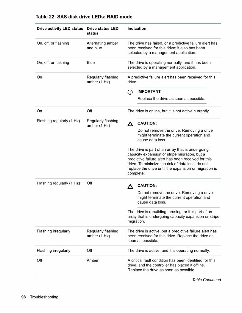
Table 22: SAS disk drive LEDs: RAID mode
Drive activity LED status Drive status LEDstatus
Indication
On, off, or flashing Alternating amberand blue
The drive has failed, or a predictive failure alert hasbeen received for this drive; it also has beenselected by a management application.
On, off, or flashing Blue The drive is operating normally, and it has beenselected by a management application.
On Regularly flashingamber (1 Hz)
A predictive failure alert has been received for thisdrive.
IMPORTANT:
Replace the drive as soon as possible.
On Off The drive is online, but it is not active currently.
Flashing regularly (1 Hz) Regularly flashingamber (1 Hz) CAUTION:
Do not remove the drive. Removing a drivemight terminate the current operation andcause data loss.
The drive is part of an array that is undergoingcapacity expansion or stripe migration, but apredictive failure alert has been received for thisdrive. To minimize the risk of data loss, do notreplace the drive until the expansion or migration iscomplete.
Flashing regularly (1 Hz) Off CAUTION:
Do not remove the drive. Removing a drivemight terminate the current operation andcause data loss.
The drive is rebuilding, erasing, or it is part of anarray that is undergoing capacity expansion or stripemigration.
Flashing irregularly Regularly flashingamber (1 Hz)
The drive is active, but a predictive failure alert hasbeen received for this drive. Replace the drive assoon as possible.
Flashing irregularly Off The drive is active, and it is operating normally.
Off Amber A critical fault condition has been identified for thisdrive, and the controller has placed it offline.Replace the drive as soon as possible.
Table Continued
98 Troubleshooting
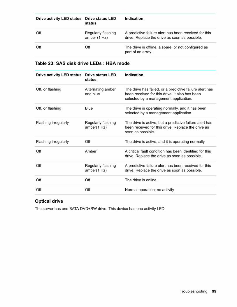
Drive activity LED status Drive status LEDstatus
Indication
Off Regularly flashingamber (1 Hz)
A predictive failure alert has been received for thisdrive. Replace the drive as soon as possible.
Off Off The drive is offline, a spare, or not configured aspart of an array.
Table 23: SAS disk drive LEDs : HBA mode
Drive activity LED status Drive status LEDstatus
Indication
Off, or flashing Alternating amberand blue
The drive has failed, or a predictive failure alert hasbeen received for this drive; it also has beenselected by a management application.
Off, or flashing Blue The drive is operating normally, and it has beenselected by a management application.
Flashing irregularly Regularly flashingamber(1 Hz)
The drive is active, but a predictive failure alert hasbeen received for this drive. Replace the drive assoon as possible.
Flashing irregularly Off The drive is active, and it is operating normally.
Off Amber A critical fault condition has been identified for thisdrive. Replace the drive as soon as possible.
Off Regularly flashingamber(1 Hz)
A predictive failure alert has been received for thisdrive. Replace the drive as soon as possible.
Off Off The drive is online.
Off Off Normal operation; no activity
Optical driveThe server has one SATA DVD+RW drive. This device has one activity LED.
Troubleshooting 99
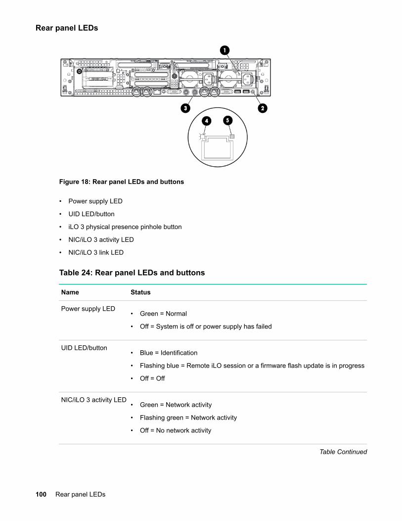
Rear panel LEDs
Figure 18: Rear panel LEDs and buttons
• Power supply LED
• UID LED/button
• iLO 3 physical presence pinhole button
• NIC/iLO 3 activity LED
• NIC/iLO 3 link LED
Table 24: Rear panel LEDs and buttons
Name Status
Power supply LED• Green = Normal
• Off = System is off or power supply has failed
UID LED/button• Blue = Identification
• Flashing blue = Remote iLO session or a firmware flash update is in progress
• Off = Off
NIC/iLO 3 activity LED• Green = Network activity
• Flashing green = Network activity
• Off = No network activity
Table Continued
100 Rear panel LEDs

Name Status
NIC/iLO 3 link LED• Green = Network link
• Off = No network link
iLO 3 physicalpresence pinholebutton
The iLO 3 physical presence button enables you to reset iLO 3 and gain accessto the system if all iLO passwords are lost. A momentary press causes a softreset of iLO 3 when the button is released. The iLO 3 Physical Presence buttonenables you to reset iLO, enter TPM physical presence mode, and enter securityoverride mode.
• A momentary press of the button resets iLO, clears any security override orTPM physical presence mode that were initiated by this button, and returnsthe serial port to iLO mode.
• A greater than 4-second and less than 8-second press of the button placesthe system in physical presence mode for up to 15 minutes.
• A greater than 8-second and less than 12-second press of this button placesiLO into security override mode for up to 15 minutes. Security override modeenables you to enter iLO without being challenged for a password enablingyou to set up users.
• The UID LED blinks once after holding the button for 4 seconds and onceafter holding the button for 8 seconds to help you gauge how long the buttonpress has been held.
NOTE:
The iLO 3 physical presence pinhole button is located behind the sheetmetal grill and the circular punch-out in the rear panel.
Power supplyThe server is equipped with one or two power supplies, labeled PS1 and PS2. Each power supply has anAC power input receptacle and an LED that indicates the power state of the server.
The server has the following power states: standby power, full power, and off. To achieve the standbypower state, plug the power cord into the appropriate receptacle at the rear of the server. To achieve fullpower, plug the power cord into the appropriate receptacle, and either push the power button or enter theiLO 3 MP PC command. In the off state, the power cords are not connected to a power source.
Table 25: Power supply LED states
LED state Indication
Off No AC power
Green Full power on; normal operation
DiagnosticsA suite of offline and online support tools are available to enable manufacturing, field support personnel,and the customer to troubleshoot system issues. In general, if the operating system is already running,
Diagnostics 101
then Hewlett Packard Enterprise recommends that you do not shut it down and instead, use the onlinesupport tools.
If the operating system cannot be booted, then use the offline support tools to help resolve the issue. Theoffline support tools are available either from the UEFI partition, or from the IPF Offline Diagnostics andUtilities CD (IPF systems only). After the issue preventing booting has been resolved, boot the operatingsystem, and then use the online support tools for any further testing.
If you cannot reach UEFI from either the main disk or from a CD, you must troubleshoot, using the visualfault indicators, console messages, and system error logs that are available.
Online diagnostics and exercisersOnline support tools are available which permit centralized error archiving, and which provide hardwareinventory tools, as long as the agents/providers that support them are installed on the managed server.
On HP-UX systems, the legacy tools within OnlineDiag are supported. The online support tools, on theHP-UX 11.23 and greater operating systems, include the WBEM features added by SysFaultMgmt.
Verifiers quickly determine whether or not a specific device is operational by performing tasks similar innature to the way applications use the device. No license is required to run the verifiers.
Diagnostics are tools designed to identify faulty or failed CRUs.
Exercisers stress devices in order to facilitate the reproduction of intermittent issues.
Information modules create a log of information specific to one device, including:
The product identifier
A description of the device
The hardware path to the device
The vendor
Onboard log information (if applicable)
Miscellaneous information associated with the device
The firmware revision code, if firmware is present in the device, is also displayed
Expert tools are device-specific troubleshooting utilities for use by sophisticated users. Their functionalityvaries from tool to tool, but they are intended to be interactive, and rely on users to provide informationnecessary to perform a particular task. These tools require users to have the appropriate license, if theywish to run them.
Online support tool availabilityOnline diagnostics are included in the HP-UX OE media, and are installed by default.
Online support tools listThe following online support tools are available on HP-UX 11.31 hosted systems. In some cases, a tool,such as a disk exerciser, is generic to many types of hardware; in other cases, a tool, such as a tapediagnostic. is specific to a particular technology or type of tape drive.
102 Online diagnostics and exercisers

Table 26: Online Support Tools List
Functional Area Information Verify Exercise Diagnose Expert
System Yes No No No No
Processor/FPU No No Yes No Yes
Memory Yes No Yes No No
Graphics Yes Yes Yes No No
Core I/O LAN Yes Yes Yes Yes No
Disk/Arrays Yes Yes Yes No No
Tape Yes Yes Yes Yes Yes
M/O Yes No No No Yes
Add-On NetworkI/O Cards
Yes Yes Yes No Yes
Add-On MassStorage I/O Cards
Yes No No No No
Offline support tools listTable 27: Offline Support Tools List
Offline Tool Functional Area
DFDUTIL SAS/SCSI Disk Firmware Update Utility
COPYUTIL Data Copy Utility
Offline support tools list 103
Fault management overviewThe goal of fault management and monitoring is to increase system availability, by moving from a reactivefault detection, diagnosis, and repair strategy to a proactive fault detection, diagnosis, and repair strategy.The objectives are as follows:
To detect issues automatically, as nearly as possible to when they actually occur.
To diagnose issues automatically, at the time of detection.
To automatically report in understandable text a description of the issue, the likely causes of the issue, therecommended actions to resolve the issue, and detailed information about the issue.
To ensure that tools are available to repair or recover from the fault.
HP-UX fault managementProactive fault prediction and notification is provided on HP-UX by SysFaultMgmt WBEM indicationproviders. WBEM provides frameworks for monitoring and reporting events.
SysFaultMgmt WBEM indication providers enable users to monitor the operation of a wide variety ofhardware products, and alert them immediately if any failure or other unusual event occurs. By usinghardware event monitoring, users can virtually eliminate undetected hardware failures that could interruptsystem operation or cause data loss.
104 Fault management overview

WBEM indication providersHardware monitors are available to monitor the following components (These monitors are distributedfree on the OE media):
Server/fans/environment
CPU monitor
UPS monitor*
FC hub monitor*
FC switch monitor*
Memory monitor
Core electronics components
Disk drives
Ha_disk_array
NOTE:
No SysFaultMgmt WBEM indication provider is currently available for components followed by anasterisk.
OpenVMS fault management and monitoringHPE WBEM Provider software enables monitoring the health of Integrity servers running OpenVMS. Moreinformation on WBEM providers is available at http://www.hpe.com (search "WBEM providers").
Web Based Enterprise Services (WEBES) suite of tools aids monitoring and diagnosing the OpenVMSsystems.
http://www.hpe.com/support/WEBES_Overview
See the HPE OpenVMS System Manager's Manual, Volume 2: Tuning, Monitoring, andComplex Systems document for OpenVMS specific monitoring tips available at http://www.hpe.com/support/hpesc (search for the manual title).
Errors and reading error logs
Event log definitionsOften the underlying root cause of an MCA event is captured by system or iLO MP firmware in both theSystem Event and Forward Progress Logs (SEL and FPL, respectively). These errors are easily matchedwith MCA events by their timestamps. For example, the loss of a processor VRM might cause a
WBEM indication providers 105
processor fault. Decoding the MCA error logs would only identify the failed processor as the most likelyfaulty CRU. Following are some important points to remember about events and event logs:
• Event logs are the equivalent of the old server logs for status or error information output.
• Symbolic names are used in the source code; for example,
MC_CACHE_CHECK.
• The hex code for each event log is 128 bits long with an architected format:
◦ Some enumerated fields can be mapped to defined text strings.
◦ All can be displayed in hex, keyword, or text mode.
• Events are created by firmware or OS code, and are sent over the PDH bus to the iLO MP for storagein either or both of the SEL and FPL logs (HP-UX shows an I/O path for the iLO MP).
• The iLO 3 MP can display event logs: SEL events are sent over the IPMB.
• Event logs can also be read back over the PDH bus by software (for example, the IPMI driver oragent) for storage on disk.
Using event logsTo consult the event logs:
Procedure
1. Connect to the system console.
2. Use Ctrl-B to access the iLO 3 MP menu.
3. Use the sl command to view event logs: System Event (E) and Forward Progress (F) logs are veryuseful in determining the context of an error (see the following figure for an example):
NOTE:
Remember that:
• E shows only event logs for Warning, Critical, or Fatal faults by default; F shows all event logoutputs.
• System Event Logs are never overwritten, unless they are first manually cleared. When the SELis filled, no more events are logged. Forward Progress Logs (FPL) are circular and containadditional, non-critical information.
• The alert threshold can be changed.
iLO 3 MP event logsThe iLO 3 MP provides diagnostic and configuration capabilities. See the HPE Integrity iLO 3 OperationsGuide for details on the iLO 3 MP commands.
http://www.hpe.com/info/integrity_servers-docs
To access the iLO 3 MP:
106 Using event logs

NOTE:
The iLO 3 MP must be accessed from a terminal console which has access to the iLO 3 MP.
Procedure
1. Log in with proper username and password.
2. Press cl to display the console history log. This log displays console history from oldest to newest.
3. Press sl to display the status logs. The status logs consist of:
a. System Event
b. Forward Progress
c. iLO Event
d. Clear SEL and FPL
e. Live Events
4. For a more information on configuring the iLO 3 MP and using the iLO 3 MP commands, see the HPEIntegrity iLO 3 MP Operations Guides.
System event log reviewSee the HPE Integrity iLO 3 Operations Guide for this procedure.
http://www.hpe.com/info/integrity_servers-docs
Supported configurationsThis subsection provides a system build-up procedure.
System event log review 107

Server block diagramServer block diagram
Figure 19: Server Block Diagram
System build-up troubleshooting procedureUse this procedure only when the system powers on and remain powered on but does not enter into orpass power-on self test (POST) or does not boot to the UEFI menu.
Procedure
1. Remove the AC power cord from each power supply and extend the server, if racked.
2. Remove all of the SAS disk drives from the front of the server.
3. Remove the top cover to gain access to, and remove all CRUs, except the system board.
NOTE:
In the following steps, CRU and FRU are used interchangeably.
4. Plug in the AC power cords. The iLO 3 MP and system console appears. At the console, execute theMP DF command. The following CRU IDs appear. Your display might not exactly match the displayshown:
FRU IDs:--------00-System Board 02-Display Board 05-Power Supply 1 42-Virtual Connect
108 Server block diagram

5. If you do not see all of the above CRU IDs then concentrate on the missing CRU IDs.
6. Remove the AC power cords. Add a processor in the CPU 0 socket and add a memory expansionboard with DIMMs populated in slots 4A and 3A. Plug in the AC power cords and check for theprocessor, memory expansion board, and DIMM FRU IDs.
7. The following is an example of the MP DF command that appears with a processor, memoryexpansion board, and two DIMMs installed.
NOTE:
Your display might not exactly match the display shown.
8.FRU IDs:--------
00-System Board 02-Display Board 05-Power Supply 1 0C-Memory Riser 1 20-Processor 0 24-Processor 0 RAM 42-Virtual Connect 82-DIMM CPU0-R1 3A 83-DIMM CPU0-R1 4A
9. If you do not see all of the above CRU IDs then concentrate on the missing CRU IDs.
10. Power on the server and check the SEL for any IPMI alerts related to the processor.
NOTE:
Your display might not exactly match the display shown.
Log Entry 4: 01 Aug 2012 17:22:00Alert Level 7: FatalKeyword: BOOT_NOT_DETECTEDNo events were received from system firmwareLogged by: integrated Lights Out Sensor: Processor Data1: FRB2/Hang in POST failure20501965B8020006 FFFF036F00070400
11. If the above Level 7 IPMI alert appears, verify the installation of your processor and if necessaryreplace the processor.
12. If the processor is installed and functioning properly, check the SEL for the following IPMI event afterpowering on the server to verify that POST has started.
NOTE:
Your display might not exactly match the display shown.
Log Entry 3: 02 Aug 2012 11:28:16Alert Level 2: InformationalKeyword: BOOT_STARTCPU starting bootLogged by: System Firmware located in socket 0,cpu 2,thread 0 Data: Major change in system state - Boot Start5480006309E10005 0000000000000000
13. Check the SEL for any memory-related IPMI alerts.
Troubleshooting 109
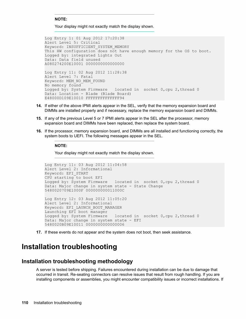
NOTE:
Your display might not exactly match the display shown.
Log Entry 1: 01 Aug 2012 17:20:38Alert Level 5: CriticalKeyword: INSUFFICIENT_SYSTEM_MEMORYThis HW configuration does not have enough memory for the OS to boot.Logged by: integrated Lights Out Data: Data field unusedA080274200E10001 0000000000000000
Log Entry 11: 02 Aug 2012 11:28:38Alert Level 7: FatalKeyword: MEM_NO_MEM_FOUNDNo memory foundLogged by: System Firmware located in socket 0,cpu 2,thread 0 Data: Location - Blade (Blade Board)E48000D109E10010 FFFFFFFFFFFFFF94
14. If either of the above IPMI alerts appear in the SEL, verify that the memory expansion board andDIMMs are installed properly and if necessary, replace the memory expansion board and DIMMs.
15. If any of the previous Level 5 or 7 IPMI alerts appear in the SEL after the processor, memoryexpansion board and DIMMs have been replaced, then replace the system board.
16. If the processor, memory expansion board, and DIMMs are all installed and functioning correctly, thesystem boots to UEFI. The following messages appear in the SEL.
NOTE:
Your display might not exactly match the display shown.
Log Entry 11: 03 Aug 2012 11:04:58Alert Level 2: InformationalKeyword: EFI_STARTCPU starting to boot EFILogged by: System Firmware located in socket 0,cpu 2,thread 0 Data: Major change in system state - State Change5480020709E1000F 000000000011000C
Log Entry 12: 03 Aug 2012 11:05:20Alert Level 2: InformationalKeyword: EFI_LAUNCH_BOOT_MANAGERLaunching EFI boot managerLogged by: System Firmware located in socket 0,cpu 2,thread 0 Data: Major change in system state - EFI5480020B09E10011 0000000000000006
17. If these events do not appear and the system does not boot, then seek assistance.
Installation troubleshooting
Installation troubleshooting methodologyA server is tested before shipping. Failures encountered during installation can be due to damage thatoccurred in transit. Re-seating connectors can resolve issues that result from rough handling. If you areinstalling components or assemblies, you might encounter compatibility issues or incorrect installations. If
110 Installation troubleshooting
you are installing components or assemblies, verify that items are correctly installed and that allconnectors are fully engaged. If the unit does not power on, verify the power source before proceeding.
If an issue is encountered during initial operation, remove any add-in or optional components, and thenretest the server before continuing. Verify basic server operation before installing additional cards, andconfiguring software and hardware for the server requirements.
Troubleshooting is based on observation of server status indications and error messages, and byreviewing system event logs. You can observe the LED indicators on the front and rear of the server.Error messages appear on local and remote consoles. System history (console, event, and history logs) isavailable through the iLO 3 MP, and is accessed through the console. Additional information abouttroubleshooting is available on the CD provided with the server.
Installation troubleshooting using the server power buttonThe server power button on the front panel operates differently depending on how long the button ispressed, and on what the system is doing when the button is pressed. You must be aware of the uses toproperly troubleshoot the system.
Table 28: Server power button functions when server is on and at UEFI
Action Reaction
1-3 seconds System power turns off immediately (hard power off)
5 seconds or longer System power turns off immediately (hard power off)
Table 29: Server power button functions when server is on and OS is running
Action Reaction
1-3 seconds System power turns off (software-controlled power off)
5 seconds or longer System power turns off immediately (hard power off)
If the server is off, and power is not connected to the server power supplies, pressing the power buttonhas no effect.
If the server is off, and power is connected to server power supplies, the front panel power LED flashes ata 1 Hz rate. In this state, standby power is available to server circuits, but main power is off.
Table 30: Server power button functions when server is off
Action Reaction
1-3 seconds System power turns on
Server does not power onThe server power button on the front panel operates differently depending on how long the button ispressed, and on what the system is doing when the button is pressed. You must be aware of its uses toproperly troubleshoot the system.
Installation troubleshooting using the server power button 111

NOTE:
If the server is off, and power is not connected to server power supplies, pressing the power buttonhas no effect.
Power issues during installation are usually related to the installation process. If the server does notpower on, view the LED indicators on the power supply rear panels and perform the following:
• If the AC power LED on the power supply on the rear panel of the server is lit, power is available to theserver.
• If the AC power LED is not lit, the server is either in standby power mode, or an issue may haveoccurred. Re-seat the power supply. If the issue persists, remove and re-seat the board within theserver. If the issue still persists, replace the power supply or the power supply interface board.
UEFI menu is not availableIf you cannot access the UEFI from either the main disk partition or the CD, use the following tools toresolve the issue:
• Front panel LEDs
• iLO 3 MP
◦ Console messages
◦ SEL
◦ FPL
Operating system does not bootIf the operating system does not boot, boot to UEFI, and use the following tools to view the system logs.Analyze any error messages to resolve the issue.
• UEFI Shell
• iLO 3
Operating system boots with issuesIf the operating system is running and you are experiencing issues, use the following tools to resolve theissue:
• LEDs
• Error Messages and event logs
Intermittent server issuesYou can usually trace intermittent issues that occur during installation to power source issues, a looseconnector, or some other hardware issue. If you are experiencing intermittent issues:
112 UEFI menu is not available

Procedure
1. View iLO 3 MP logs and analyze the issue. Determine if there is more than one symptom and if theissue is random.
2. Verify that the AC power source is stable.
3. Re-seat all rear panel connectors.
4. Re-seat all hot-swap fans and power supplies.
5. Re-seat all main memory DIMMs.
6. Re-seat all cable harnesses and board connectors.
SATA DVD+RW drive issuesSATA DVD+RW drive issues that occur during installation are usually related to faulty connections. If youare experiencing DVD drive issues:
Procedure
1. Remove and reinsert the media.
2. Replace the media.
3. Remove and reinstall the DVD drive. Verify that connectors are fully engaged.
4. Replace the DVD drive.
5. Re-seat cables.
SAS disk drive issuesHard drive issues that occur during installation are usually due to rough handling. The drive may not becorrectly seated or may have been damaged in transit. If you are experiencing hard drive issues:
Procedure
1. Remove and reinsert the faulty hard drive.
2. Swap the hard drive with one from another slot or with a known good spare.
3. Remove and reinstall the hard drive backplane. Verify that connectors are fully engaged.
4. Replace the hard drive backplane.
5. Re-seat cables.
Console issuesConsole issues during installations can be caused by faulty interconnections. If you are experiencingmonitor, keyboard, or mouse issues:
Procedure
1. View the monitor controls. Adjust contrast and brightness as required.
2. Inspect all power and interconnecting cables. Verify that all console connectors are fully engaged.
SATA DVD+RW drive issues 113
3. Verify that all iLO 3 MP board connectors are fully engaged.
4. Exercise the appropriate self-test features of the console software.
Troubleshooting the processor and memoryCause
All of the processor and memory controller functions are integrated into the processor. DIMMs reside onthe memory expansion boards, and PCIe bus controller chips reside on the I/O riser and the systemboard. This section discusses the roles of logical processors, and physical memory ranks.
Troubleshooting the server processor
Cause
The server supports both dual-core and quad-core processors. Each server supports one or twoprocessor modules. The dual-core processor modules contain two individual processor cores. When twoprocessor modules are installed in the server, the server contains four physical processors.
Furthermore, each physical processor core contains logic to support two physical threads. When twodual-core processor modules are installed and enabled in the server, the server supports up to eightthreads, or the equivalent of eight logical processors.
Processor load orderFor a minimally loaded server, one processor module must be installed in processor socket 0 on thesystem board, and the threads must be enabled by user actions. Additional processor modules of thesame revision are installed in processor socket 1 for the server.
Processor module behaviorsLocal MCA events can cause the physical processor core and one or both of the logical processors withinthat processor module to fail while all other physical and their logical processors continue operating.Double-bit data cache errors in any physical processor core causes a Global MCA event, which, in turn,causes all logical and physical processors in the server to fail and reboot the operating system.
Customer messaging policy
• A diagnostic LED only illuminates for physical processor core errors, when isolation is to a specific IPFprocessor module. If there is any uncertainty about a specific processor, then the customer is pointedto the SEL for any action, and the suspect IPF processor module CRU LED on the System InsightDisplay does not illuminate.
• For configuration-type errors (for example, when no IPF processor module is installed in processor slot0) all of the CRU LEDs on the diagnostic LED panel illuminate for all of the IPF processors that aremissing.
• No diagnostic messages are reported for single-bit errors that are corrected in both instruction anddata caches, during CMC events to any physical processor core. Diagnostic messages are reportedfor CMC events when thresholds are exceeded for single-bit errors; fatal processor errors causeglobal / local MCA events.
114 Troubleshooting the processor and memory
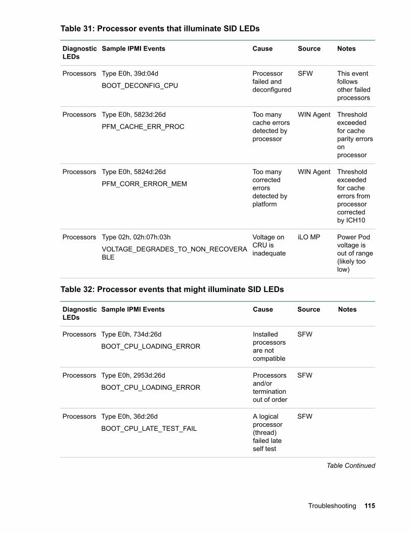
Table 31: Processor events that illuminate SID LEDs
DiagnosticLEDs
Sample IPMI Events Cause Source Notes
Processors Type E0h, 39d:04d
BOOT_DECONFIG_CPU
Processorfailed anddeconfigured
SFW This eventfollowsother failedprocessors
Processors Type E0h, 5823d:26d
PFM_CACHE_ERR_PROC
Too manycache errorsdetected byprocessor
WIN Agent Thresholdexceededfor cacheparity errorsonprocessor
Processors Type E0h, 5824d:26d
PFM_CORR_ERROR_MEM
Too manycorrectederrorsdetected byplatform
WIN Agent Thresholdexceededfor cacheerrors fromprocessorcorrectedby ICH10
Processors Type 02h, 02h:07h:03h
VOLTAGE_DEGRADES_TO_NON_RECOVERABLE
Voltage onCRU isinadequate
iLO MP Power Podvoltage isout of range(likely toolow)
Table 32: Processor events that might illuminate SID LEDs
DiagnosticLEDs
Sample IPMI Events Cause Source Notes
Processors Type E0h, 734d:26d
BOOT_CPU_LOADING_ERROR
Installedprocessorsare notcompatible
SFW
Processors Type E0h, 2953d:26d
BOOT_CPU_LOADING_ERROR
Processorsand/orterminationout of order
SFW
Processors Type E0h, 36d:26d
BOOT_CPU_LATE_TEST_FAIL
A logicalprocessor(thread)failed lateself test
SFW
Table Continued
Troubleshooting 115
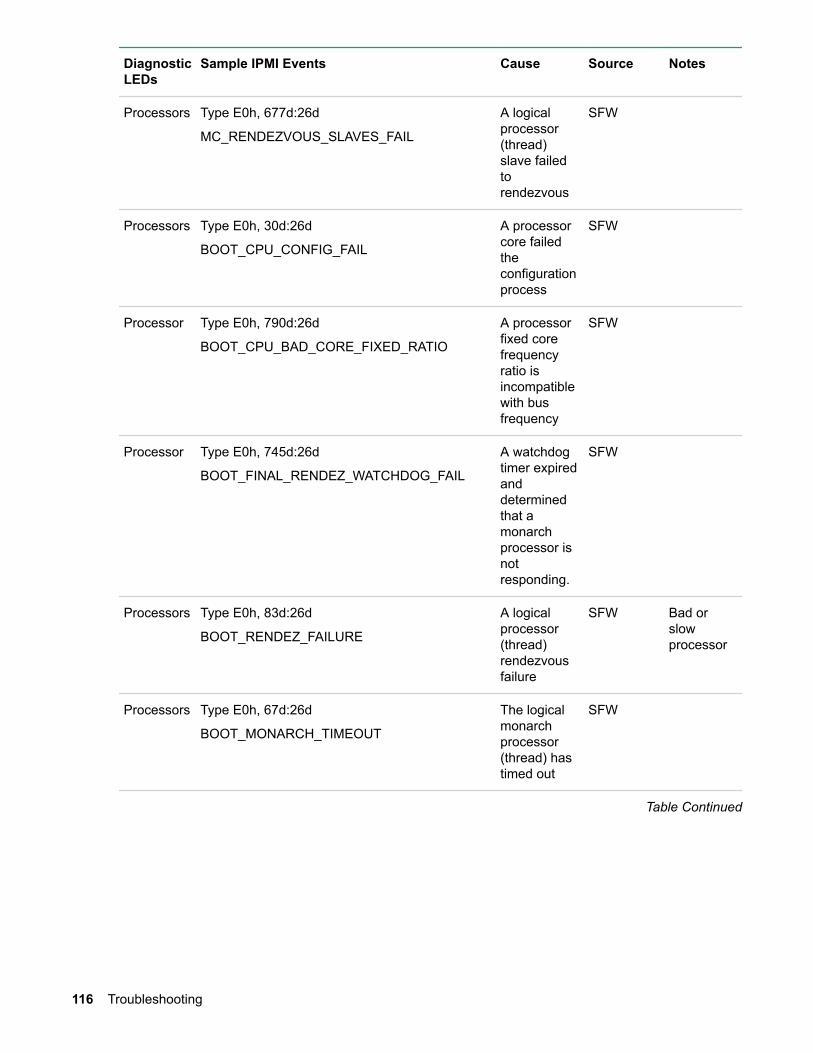
DiagnosticLEDs
Sample IPMI Events Cause Source Notes
Processors Type E0h, 677d:26d
MC_RENDEZVOUS_SLAVES_FAIL
A logicalprocessor(thread)slave failedtorendezvous
SFW
Processors Type E0h, 30d:26d
BOOT_CPU_CONFIG_FAIL
A processorcore failedtheconfigurationprocess
SFW
Processor Type E0h, 790d:26d
BOOT_CPU_BAD_CORE_FIXED_RATIO
A processorfixed corefrequencyratio isincompatiblewith busfrequency
SFW
Processor Type E0h, 745d:26d
BOOT_FINAL_RENDEZ_WATCHDOG_FAIL
A watchdogtimer expiredanddeterminedthat amonarchprocessor isnotresponding.
SFW
Processors Type E0h, 83d:26d
BOOT_RENDEZ_FAILURE
A logicalprocessor(thread)rendezvousfailure
SFW Bad orslowprocessor
Processors Type E0h, 67d:26d
BOOT_MONARCH_TIMEOUT
The logicalmonarchprocessor(thread) hastimed out
SFW
Table Continued
116 Troubleshooting
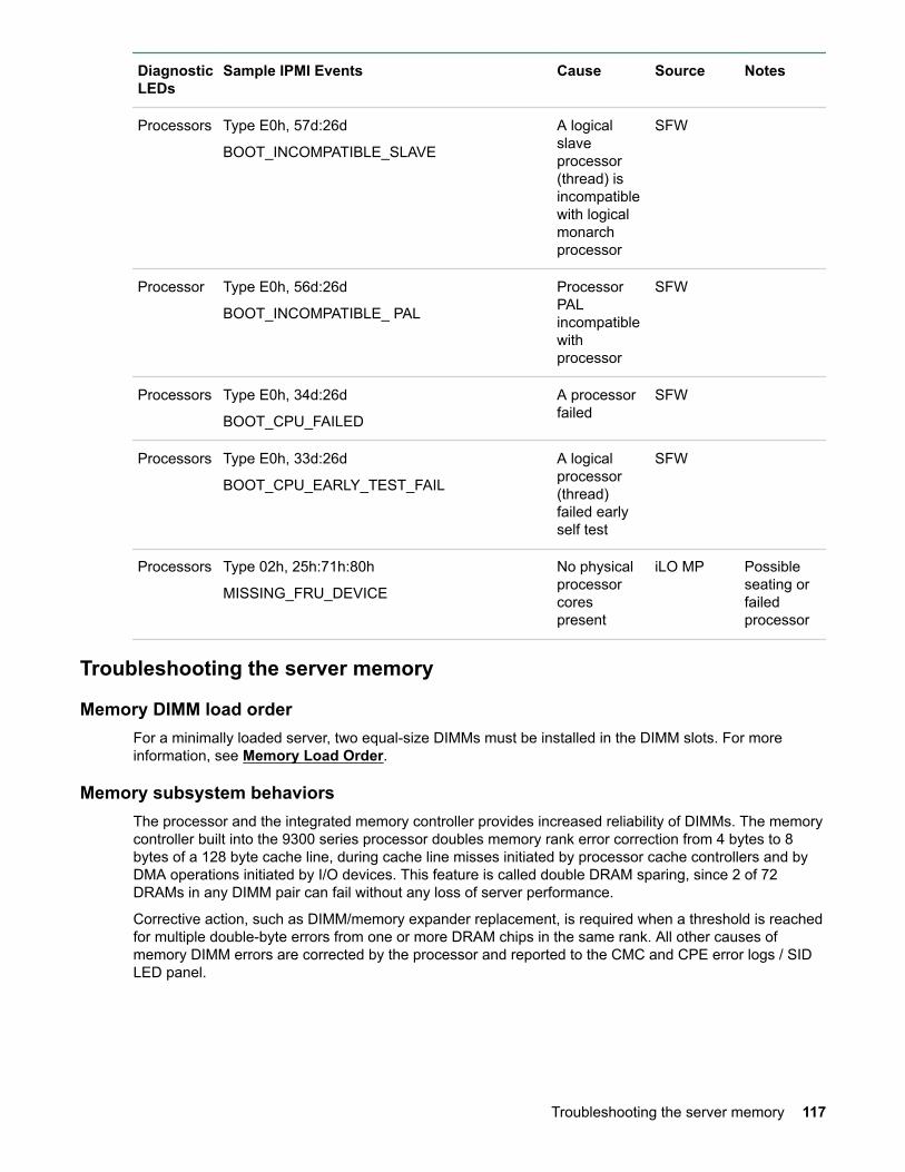
DiagnosticLEDs
Sample IPMI Events Cause Source Notes
Processors Type E0h, 57d:26d
BOOT_INCOMPATIBLE_SLAVE
A logicalslaveprocessor(thread) isincompatiblewith logicalmonarchprocessor
SFW
Processor Type E0h, 56d:26d
BOOT_INCOMPATIBLE_ PAL
ProcessorPALincompatiblewithprocessor
SFW
Processors Type E0h, 34d:26d
BOOT_CPU_FAILED
A processorfailed
SFW
Processors Type E0h, 33d:26d
BOOT_CPU_EARLY_TEST_FAIL
A logicalprocessor(thread)failed earlyself test
SFW
Processors Type 02h, 25h:71h:80h
MISSING_FRU_DEVICE
No physicalprocessorcorespresent
iLO MP Possibleseating orfailedprocessor
Troubleshooting the server memory
Memory DIMM load orderFor a minimally loaded server, two equal-size DIMMs must be installed in the DIMM slots. For moreinformation, see Memory Load Order.
Memory subsystem behaviorsThe processor and the integrated memory controller provides increased reliability of DIMMs. The memorycontroller built into the 9300 series processor doubles memory rank error correction from 4 bytes to 8bytes of a 128 byte cache line, during cache line misses initiated by processor cache controllers and byDMA operations initiated by I/O devices. This feature is called double DRAM sparing, since 2 of 72DRAMs in any DIMM pair can fail without any loss of server performance.
Corrective action, such as DIMM/memory expander replacement, is required when a threshold is reachedfor multiple double-byte errors from one or more DRAM chips in the same rank. All other causes ofmemory DIMM errors are corrected by the processor and reported to the CMC and CPE error logs / SIDLED panel.
Troubleshooting the server memory 117

Customer messaging policy
• The diagnostic LED illuminates only for memory DIMM errors when isolated to a specific DIMM. Ifthere is uncertainty about a specific DIMM, then the customer is pointed to the SEL for any actions,and the DIMM CRU LED for the suspect DIMM on the System Insight Display is not lit.
• For configuration-type errors, for example, the CRU LEDs on the SID LED panel illuminate for allDIMMs that are not installed.
• No diagnostic messages are reported for single-byte errors that are corrected in both ICH10 cachesand DIMMs during CPE events. Diagnostic messages are reported for CPE events when thresholdsare exceeded for both single-byte and double byte errors; all fatal memory subsystem errors causeglobal MCA events.
Table 33: Memory subsystem events that illuminate SID LEDs
DiagnosticLEDs
Sample IPMI Events Cause Source Notes
DIMMs Type E0h, 208d:04d
MEM_NO_DIMMS_INSTALLED
No DIMMs installedon one or moreprocessors
SFW
DIMMs Type E0h, 172d:04d
MEM_DIMM_SPD_CHECKSUM
A DIMM has a serialpresence detect(SPD) EEPROM witha bad checksum
SFW Either EEPROMismisprogrammedor this DIMM isincompatible
DIMMs Type E0h, 4652d:26d
WIN_AGT_PREDICT_MEM_FAIL
This memory rank iscorrecting too manysingle-bit errors
WINAgent
Memory rank isabout to fail orenvironmentalconditions arecausing moreerrors thanusual
Table 34: Memory subsystem events that might illuminate SID LEDs
DiagnosticLEDs
Sample IPMI Events Cause Source Notes
DIMMs Type E0h, 174d:26d
MEM_DIMM_TYPE_INCOMPATIBLE
DIMM type is notcompatible withcurrent DIMMs for thisplatform
SFW
Troubleshooting the power subsystemCause
The two power supply CRUs for the server provides N+1 redundancy for the server. Each power supplyCRU is identified by the server as 1 and 2 for logging purposes. The power supplies have correspondingLEDs on the diagnostic LED panel.
118 Customer messaging policy

NOTE:
Power supply CRU failures are identified visually by a single green LED that is turned off when oneor both of the power supplies fail; logged as an IPMI event by voltage sensor logic; and identified asa power supply CRU failure by iLO3 turning on the appropriate LEDs on the front LED panel.
The Power Supply LED on the SID panel illuminates only when a failure or fault is detected in apower supply. Loss of AC power to a power supply generates an SEL entry, but does not result inthe Power Supply LED becoming illuminated.
The System Health LED does not change status if AC power is removed from a single power supplyin a rx2800 i2 server system with power redundancy.
Power subsystem behaviorFor the server, each bulk power supply CRU provides 800 watts of DC power from a nominal 120 VAC,50-60 Hz; and 1200 watts from a nominal 240 VAC, 50-60 Hz. The iLO MP chip located on the systemboard controls the flow of +12 V DC power to the server CRUs. You can control and display power supplystatus remotely with the iLO 3 MP pc and ps commands, respectively.
Typical power up sequence of the server is as follows:
Procedure
1. Power LED on front panel glows steady amber when one or two bulk power supplies are plugged intonominal AC voltage and the +3.3 VDC housekeeping voltage comes on and stays on whenever ACpower is present.
2. The iLO 3 MP, Flash memory, and server intrusion circuits are reset after the +3.3 V DC housekeepingvoltage stabilizes.
3. The iLO 3 MP monitors the power button on the front panel.
4. When the power button is pressed, iLO 3 signals the bulk power supplies to fully power up.
5. The +12 V DC rail comes up and all of the cooling fans and the various Voltage Regulators come upsequentially.
6. The iLO 3 MP signals when the server is ready to come out of reset (clocks are programmed andstable, etc.).
7. The server is brought out of reset, and begins the boot process.
Power LED buttonThe front panel system power LED indicates the status of system power. The LED is incorporated insidethe power button itself.
The power button has a momentary switch (as opposed to a latching switch) that is recessed or coveredto prevent accidental activation or deactivation.
If the OS is up, pressing the power button for less than four seconds results in a graceful shutdown of theoperating system and a subsequent removal of system power. Pressing the power button for greater thanfour seconds results in a hard shutdown (system power removed). While the server is booting (before thesystem has passed UEFI_EXIT_BOOT_SERVICES), the iLO MP immediately powers the server off on abutton press, since there is no concept of soft shutdown in this state.
In the event that the OS is absent or hung, or that the manageability subsystem (specifically the iLO MP)in the server is not responding, a greater than four second press of the power button is required to poweroff the system (a less than four second press on the power button has no effect).
Power subsystem behavior 119
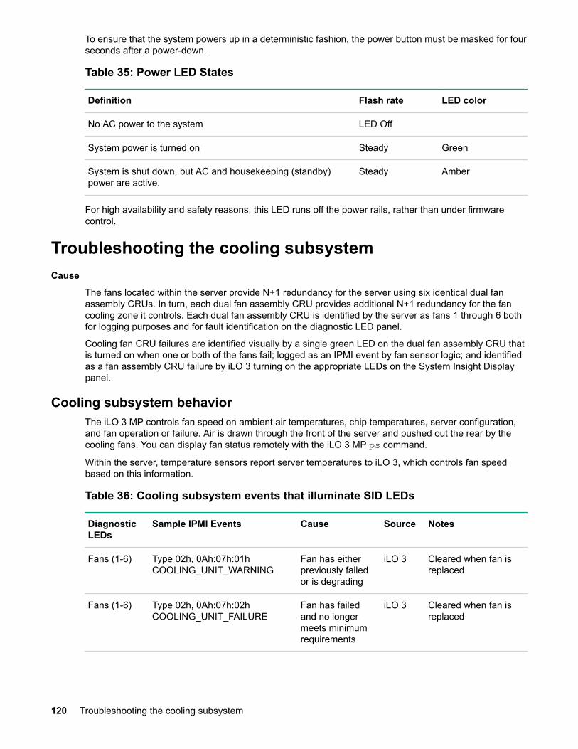
To ensure that the system powers up in a deterministic fashion, the power button must be masked for fourseconds after a power-down.
Table 35: Power LED States
Definition Flash rate LED color
No AC power to the system LED Off
System power is turned on Steady Green
System is shut down, but AC and housekeeping (standby)power are active.
Steady Amber
For high availability and safety reasons, this LED runs off the power rails, rather than under firmwarecontrol.
Troubleshooting the cooling subsystemCause
The fans located within the server provide N+1 redundancy for the server using six identical dual fanassembly CRUs. In turn, each dual fan assembly CRU provides additional N+1 redundancy for the fancooling zone it controls. Each dual fan assembly CRU is identified by the server as fans 1 through 6 bothfor logging purposes and for fault identification on the diagnostic LED panel.
Cooling fan CRU failures are identified visually by a single green LED on the dual fan assembly CRU thatis turned on when one or both of the fans fail; logged as an IPMI event by fan sensor logic; and identifiedas a fan assembly CRU failure by iLO 3 turning on the appropriate LEDs on the System Insight Displaypanel.
Cooling subsystem behaviorThe iLO 3 MP controls fan speed on ambient air temperatures, chip temperatures, server configuration,and fan operation or failure. Air is drawn through the front of the server and pushed out the rear by thecooling fans. You can display fan status remotely with the iLO 3 MP ps command.
Within the server, temperature sensors report server temperatures to iLO 3, which controls fan speedbased on this information.
Table 36: Cooling subsystem events that illuminate SID LEDs
DiagnosticLEDs
Sample IPMI Events Cause Source Notes
Fans (1-6) Type 02h, 0Ah:07h:01hCOOLING_UNIT_WARNING
Fan has eitherpreviously failedor is degrading
iLO 3 Cleared when fan isreplaced
Fans (1-6) Type 02h, 0Ah:07h:02hCOOLING_UNIT_FAILURE
Fan has failedand no longermeets minimumrequirements
iLO 3 Cleared when fan isreplaced
120 Troubleshooting the cooling subsystem
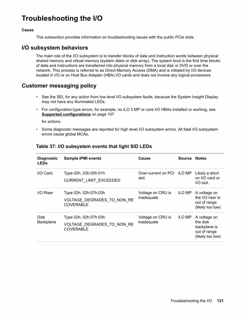
Troubleshooting the I/OCause
This subsection provides information on troubleshooting issues with the public PCIe slots.
I/O subsystem behaviorsThe main role of the I/O subsystem is to transfer blocks of data and instruction words between physicalshared memory and virtual memory (system disks or disk array). The system boot is the first time blocksof data and instructions are transferred into physical memory from a local disk or DVD or over thenetwork. This process is referred to as Direct Memory Access (DMA) and is initiated by I/O deviceslocated in I/O or on Host Bus Adapter (HBA) I/O cards and does not involve any logical processors.
Customer messaging policy
• See the SEL for any action from low level I/O subsystem faults, because the System Insight Displaymay not have any illuminated LEDs.
• For configuration-type errors, for example, no iLO 3 MP or core I/O HBAs installed or working, see Supported configurations on page 107
for actions.
• Some diagnostic messages are reported for high level I/O subsystem errors. All fatal I/O subsystemerrors cause global MCAs.
Table 37: I/O subsystem events that light SID LEDs
DiagnosticLEDs
Sample IPMI events Cause Source Notes
I/O Card Type 02h, 03h:05h:01h
CURRENT_LIMIT_EXCEEDED
Over-current on PCIslot
iLO MP Likely a shorton I/O card orI/O slot.
I/O Riser Type 02h, 02h:07h:03h
VOLTAGE_DEGRADES_TO_NON_RECOVERABLE
Voltage on CRU isinadequate
iLO MP A voltage onthe I/O riser isout of range(likely too low)
DiskBackplane
Type 02h, 02h:07h:03h
VOLTAGE_DEGRADES_TO_NON_RECOVERABLE
Voltage on CRU isinadequate
iLO MP A voltage onthe diskbackplane isout of range(likely too low)
Troubleshooting the I/O 121
Table 38: I/O card events that might illuminate SID LEDs
DiagnosticLEDs
Sample IPMI Events Cause Source Notes
I/O Card Type E0h, 4658d:26d
IO_PCI_POWER_OVERLOAD_ERR
A non hot plug I/Oslot powerconsumptionincreases the totalI/O powerconsumption beyondthe supported limit
SFW Disallow O/Sboot anddisplay thefollowing UEFIerror message,"I/Oconfigurationexceed"
I/O Card Type E0h, 137d:26d
IO_NOT_ENOUGH_POWER_ERROR
Insufficient power topower on a hot-plugPCI-X slot
SFW Display UEFIwarningmessage"Failed I/Oslotsdeconfigured"
I/O Card Type E0h, 147d:26d
IO_SLOT_STANDBY_POWER_ERROR
PCI slot standbypower failed
SFW Either a card /slot issue. Re-seat card first.
I/O Card Type E0h, 131d:26d
IO_HOT_PLUG_CTRL_FAILED
PCI-X hot-plugcontroller failed
SFW Either a card /slot issue. Re-seat card first.
I/O Card Type E0h, 139d:26d
IO_PCI_MAPPING_TOO_BIG
PCI bus walk (I/Odiscovery) resourcesexceeded
SFW Remove anyunsupportedI/O cards.Move I/O cardto an unusedPCI slot
I/O Card Type E0h, 148d:26d
IO_UNKNOWN_PCIXCAP_VAL
Found invalidPCIXCAP value
SFW
I/O Card Type E0h, 141d:26d
IO_PCIXCAP_SAMPLE_ERROR
PCIXCAP samplingerror
SFW
I/O Card Type E0h, 123d:26d
IO_CHECK_LBA_MISSING_ERR
Expected I/O hostbridge (Lower BusAdapter) is missing
SFW
I/O Card Type E0h, 619d:26d
IO_CHECK_LBA_DECONFIG_ERR
Expected I/O hostbridge (Lower BusAdapter) isdeconfigured
SFW
Table Continued
122 Troubleshooting

DiagnosticLEDs
Sample IPMI Events Cause Source Notes
I/O Card Type E0h, 133d:26dIO_LBA_CLEAR_ERR_FAILED
I/O LBA clear errorfailed
SFW
I/O Card Type E0h, 144d:26d
IO_SBA_CLEAR_ERR_FAILED
I/O SBA clear errorfailed
SFW
I/O Card Type E0h, 146d:26d
IO_SLOT_POWER_ON_ERROR
PCI-X slot power onerror
SFW
I/O Card Type E0h, 145d:26d
IO_SLOT_POWER_DEFAULT_ERROR
PCI-X slot hasincorrect defaultpower state
SFW
I/O Card Type E0h, 136d:26d
IO_LBA_RESET_ERROR
I/O host bridge(Lower Bus Adapter)is inaccessiblebecause rope resetfailed to complete
SFW
I/O Card Type E0h, 130d:26d
IO_DLL_ERROR
PCI clock DLL error SFW
I/O Card Type E0h, 143d:26d
IO_ROPE_RESET_ERROR
I/O rope reset failedto complete
SFW
I/O Card Type E0h, 7346d
CC_IODISC_LBA_LINK_TRAIN_ERR
PCIe link failed totrain
SFW
I/O Card Type E0h, 7356d
IO_PCIE_LINK_SUBOPTIMAL
PCIe link is notrunning at maxcapable bandwidth
SFW
Troubleshooting the iLO 3 MP subsystemCause
This subsection provides information on troubleshooting issues with the iLO 3 MP subsystem.
iLO 3 MP LAN LED on the rear panelThe iLO 3 MP LAN supports two LEDs, viewable from the rear of the system:
• iLO 3 LAN link LED, which indicates link speed
• iLO 3 LAN activity, which indicates link activity
Troubleshooting the iLO 3 MP subsystem 123

Table 39: iLO 3 MP LAN Activity LED states
Link status LED state
Activity Flashing green
Link with no activity Steady green
No link Off
NOTE:
For information on the LAN LED, see System LAN LEDs on page 124.
Troubleshooting the I/O subsystemCause
This subsection provides information on troubleshooting issues with the I/O subsystem.
Verifying SAS hard drive operationEach SAS disk drive has an activity LED indicator on the front of the drive.
NOTE:
On the server, only the activity LED is used. The status LED is not monitored by the OS.
Verify that the LED shows the correct activity indication for all disk drives that you installed:
Procedure
1. Turn on power to the server and display monitor.
2. During the boot sequence, watch the activity LED on each SAS disk drive.
3. The LED quickly cycles from amber to green. The LED stays steady green until the drive spins up.
4. If the activity LED stays illuminated steady green on any SAS disk drives (after the drive spins up), thedrive might not be seated correctly. Check installation as follows:
a. Turn off the server power button and unplug the AC power cords and any cables.
b. Re-seat all of the SAS disk drives installed in the server.
c. Reconnect the AC power cords and any cables. Restart the server to determine whether the LEDsnow become illuminated during the boot. If not, contact your reseller.
System LAN LEDsFour system LANs are located on the rear bulkhead of the server. These LANs are connected to thesystem board.
124 Troubleshooting the I/O subsystem
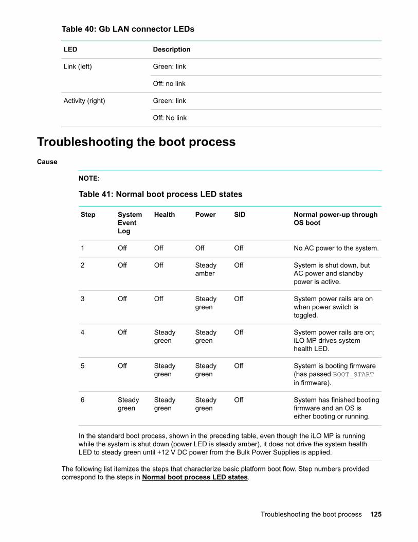
Table 40: Gb LAN connector LEDs
LED Description
Link (left) Green: link
Off: no link
Activity (right) Green: link
Off: No link
Troubleshooting the boot processCause
NOTE:
Table 41: Normal boot process LED states
Step SystemEventLog
Health Power SID Normal power-up throughOS boot
1 Off Off Off Off No AC power to the system.
2 Off Off Steadyamber
Off System is shut down, butAC power and standbypower is active.
3 Off Off Steadygreen
Off System power rails are onwhen power switch istoggled.
4 Off Steadygreen
Steadygreen
Off System power rails are on;iLO MP drives systemhealth LED.
5 Off Steadygreen
Steadygreen
Off System is booting firmware(has passed BOOT_STARTin firmware).
6 Steadygreen
Steadygreen
Steadygreen
Off System has finished bootingfirmware and an OS iseither booting or running.
In the standard boot process, shown in the preceding table, even though the iLO MP is runningwhile the system is shut down (power LED is steady amber), it does not drive the system healthLED to steady green until +12 V DC power from the Bulk Power Supplies is applied.
The following list itemizes the steps that characterize basic platform boot flow. Step numbers providedcorrespond to the steps in Normal boot process LED states.
Troubleshooting the boot process 125

3. System power switch turns on bulk power supplies and fans, and releases RESET on all processorssimultaneously, when toggled on.
5. Initial processor firmware code fetch is PAL code from EEPROM in PDH, retrieved 4 bytes at a time byDMDC in ICH10 (No shared memory or I/O devices are available at this time; for example they are notinitially configured).
5. Firmware code stack is initially in BBRAM in PDH, retrieved 4 byes at a time, through PDH and DMDbuses.
5. PAL code configures all processors.
5. SAL code configures all platform ICH10 chips, including shared memory and all responding I/Odevices.
5. Firmware code and stack are relocated to shared memory, after all x4 DIMM ranks in shared memoryare configured and tested.
5. UEFI Shell is launched from shared memory, and cache lines are retrieved 128 bytes at a time byMEMC in ICH10.
6. OS loader is launched using the UEFI device driver.
6. OS boots and starts its own device drivers.
6. OS can use runtime PAL and SAL calls, and APCI features (these abstraction layers enable platformindependence).
Troubleshooting the firmwareCause
The server has the following sets of firmware installed:
• System firmware
• iLO 3 firmware
• I/O card firmware
◦ Fibre Channel cards
◦ SAS HBA cards
◦ LAN cards
• SAS controller firmware
• SAS HDD firmware
• LOM firmware
System firmware and iLO 3 firmware must be from the same release. Independent updates are notsupported. Details about a specific release are available in the associated Release Notes.
Firmware updates are available from the Hewlett Packard Enterprise website at http://www.hpe.comunder "Support and Drivers".
Identifying and troubleshooting firmware issuesErratic system operation, or the fact that the server might not boot successfully to the UEFI Boot Manageror to the UEFI Shell, are symptoms of possible firmware issues.
126 Troubleshooting the firmware

Firmware issues are relatively rare, and, therefore, look for other causes first.
If you are attempting to resolve a firmware issue, the possible failure areas are as follows:
Procedure
1. Unsupported firmware installation
2. Corrupt firmware installation
To troubleshoot firmware issues:
• Verify that all system and iLO firmware components are from the same release (use the iLO 3 srcommand).
• Reinstall all firmware.
Updating firmwareSystem firmware updates are available from the Hewlett Packard Enterprise Support Center:
http://www.hpe.com/support/hpesc
To update your firmware:
Procedure
1. To determine the current system firmware and iLO firmware versions, use the iLO sr command.
2. Choose the appropriate firmware package from the choices available on the Hewlett PackardEnterprise Support Center web page at http://www.hpe.com/support/hpesc. To verify the firmwareversion, see the Release Notes or Installation Instructions.
To update firmware by using Smart Update Manager, see Installing the latest firmware using SmartUpdate Manager on page 42.
Troubleshooting the system consoleCause
All system console connections (VGA, USB, local RS-232 and iLO 3 MP LAN) are located on the rearpanel of the server.
HP-UX uses the RS-232 serial text connection to a terminal or terminal emulator software to controlserver operations locally.
HP-UX alternatively uses the iLO 3 LAN connection over a network to control server operations locallythrough Secure Shell, and remotely over a network through web GUI.
NOTE:
The Windows operating systems uses the VGA (monitor) and USB (keyboard and mouse)connections to control server operations locally.
RS-232 connection:
If a dummy terminal/PC running terminal emulation software is attached to the iLO MP local portand does not respond to a Ctrl-B key sequence then it is possible that the iLO MP is not operational/functional.
Updating firmware 127
Troubleshooting the server environmentCause
Ambient intake air temperature is often different from ambient room temperature. Measure the operatingtemperature and humidity directly in front of the cabinet cooling air intakes, rather than measure onlyambient room conditions.
Within the server, temperature sensors report server temperature to the iLO, which controls fan speed,based on this information.
Temperature sensors are found on:
Display panel, where a thermal sensor detects the ambient room temperature. This sensor reading is themain parameter used to regulate fan speed, under normal conditions.
See Server physical and environmental specifications on page 22 for server environmentalspecifications.
128 Troubleshooting the server environment
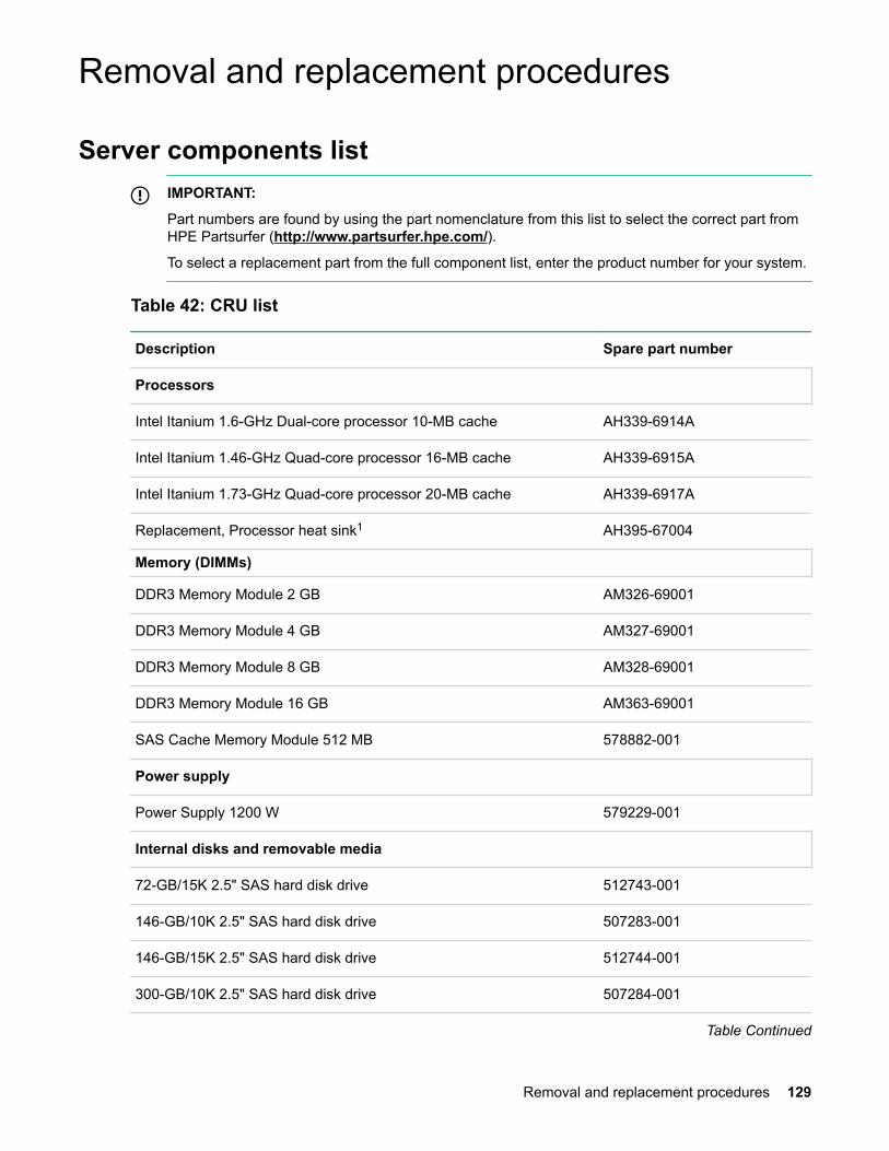
Removal and replacement procedures
Server components listIMPORTANT:
Part numbers are found by using the part nomenclature from this list to select the correct part fromHPE Partsurfer (http://www.partsurfer.hpe.com/).
To select a replacement part from the full component list, enter the product number for your system.
Table 42: CRU list
Description Spare part number
Processors
Intel Itanium 1.6-GHz Dual-core processor 10-MB cache AH339-6914A
Intel Itanium 1.46-GHz Quad-core processor 16-MB cache AH339-6915A
Intel Itanium 1.73-GHz Quad-core processor 20-MB cache AH339-6917A
Replacement, Processor heat sink1 AH395-67004
Memory (DIMMs)
DDR3 Memory Module 2 GB AM326-69001
DDR3 Memory Module 4 GB AM327-69001
DDR3 Memory Module 8 GB AM328-69001
DDR3 Memory Module 16 GB AM363-69001
SAS Cache Memory Module 512 MB 578882-001
Power supply
Power Supply 1200 W 579229-001
Internal disks and removable media
72-GB/15K 2.5" SAS hard disk drive 512743-001
146-GB/10K 2.5" SAS hard disk drive 507283-001
146-GB/15K 2.5" SAS hard disk drive 512744-001
300-GB/10K 2.5" SAS hard disk drive 507284-001
Table Continued
Removal and replacement procedures 129

Description Spare part number
450-GB/10k 2.5" SAS 6Gb Hard Disk Drive 581310-001
600-GB/10k 2.5" SAS 6Gb Hard Disk Drive 581311-001
HPE DVD ROM slimline AM242-6700A
HPE DVD+RW slimline AM243-6700A
Risers
PCIe IO Riser, 3 PCI-Express slots; 1 x8, 2 x4 496057-001
PCIe IO Riser, 2 x8 PCI-Express slots 507688-001
PCA, Memory Riser AH395-69002
Boards
PCA rx2800 i2 System board AH395-69001
PCA, Diagnostic and Front IO Board AH395-69003
SAS Disk Backplane 507690-001
Power Supply Backplane 496062-001
Fans
Replacement, Fan Module Assembly AH395-67003
Cables
Replacement Cable Kit, includes:
• Intrusion Switch and Cable
• SID Ribbon Cable
• SAS Backplane Power Cable
AH395-67002
SATA optical drive power/signal combo cable 496071-001
Cache super capacitor and cable 587324-001
Mini SAS connector and cable x2 498425-001
I/O
PCA, PCIe 2D FireMV2250 Graphics (Future release for HPEOpenVMS)
AH423-67001
Table Continued
130 Removal and replacement procedures
Description Spare part number
HPE AD337A PCle, 1000BASE-T 2P adapter AD337-60001
HPE AD338A PCle, 1000BASE-SX 2P adapter AD338-60001
HPE AD339A PS-BD, PCIe, 1000Base-T, 4p Adptr AD339-67101
HPE AD221A PCIe 1p 4 GB FC and 1P 100 AD221-67001
HPE AD222A PCIe 2p 4 GB FC and 2P 100 AD222-67001
HPE AD393A PCIe 2p 4 GB FC and 2P 100 AD393-67001
HPE Integrity 10GbE
AM225A
AM232A
AM233A
456096-001
HPE Integrity PCIe 2p P411/256 MB SAS Controller 462918-001
HPE AH400A 1-port 8 Gb PCIe FC SR QLogic HBA 489190-001
HPE AH401A 2-port 8 Gb PCIe FC SR QLogic HBA 489191-001
HPE AH402A 1-port 8 Gb PCIe FC Emulex HBA
NOTE:
Not supported on OpenVMS.
489192-001
HPE AH403A 2-port 8 Gb PCIe FC Emulex HBA
NOTE:
Not supported on OpenVMS.
489193-001
HPE AM312A (P812) 6 Gb SAS and SAS RAID Controller 587224-001
HPE AT083A IB 4X QDR CX-2 PCIe Dual Port HCA
NOTE:
Not supported on OpenVMS.
593412-001
Miscellaneous
Rack Mount Kit 574765-001
Replacement, Air Baffle AH395-67001
Table Continued
Removal and replacement procedures 131

Description Spare part number
Replacement, Air Blocker Cover AH395-67005
DVD Blank 496058-001
SAS Cache Memory Module 512 MB 578882-001
HDD cage and bezel 496074-001
System battery (CR2032) 153099-001
1 Must be replaced with a new processor.
CAUTION:
FRU components are not customer-serviceable. You must contact a Hewlett Packard Enterpriseauthorized service provider to install or replace these components.
Table 43: FRU list
Description Spare part number
Boards
HPE Integrity TPM Security Chip 505836-001
Required toolsT-10/T-15 wrench (attached to the outside of the server)
Safety considerationsBefore performing service procedures, review all the safety and electrostatic discharge information.
• For information on general safety procedures, see Safety information.
.
• For information on electrostatic discharge prevention, see Preventing electrostatic discharge.
.
Server warnings and cautionsBefore installing a server, be sure that you understand the following warnings and cautions.
132 Required tools

WARNING:
To reduce the risk of electric shock or damage to the equipment:
• Do not disable the power cord grounding plug. The grounding plug is an important safety feature.
• Plug the power cord into a grounded (earthed) electrical outlet that is easily accessible at alltimes.
• Unplug the power cord from the power supply to disconnect power to the equipment.
• Do not route the power cord where it can be walked on or pinched by items placed against it.Pay particular attention to the plug, electrical outlet, and the point where the cord extends fromthe server.
WARNING:
To reduce the risk of personal injury from hot surfaces, allow the drives and the internal systemcomponents to cool before touching them.
CAUTION:
Do not operate the server for long periods with the access panel open or removed. Operating theserver in this manner results in improper airflow and improper cooling that can lead to thermaldamage.
Preparation proceduresTo access some components and perform certain service procedures, you must perform one or more ofthe following procedures:
• Extend the server from the rack (Extending the server from the rack).
If you are performing service procedures in a Hewlett Packard Enterprise, Compaq branded, Telco, orthird-party rack cabinet, you can use the locking feature of the rack rails to support the server and gainaccess to internal components.
For more information about Telco rack solutions, see the Hewlett Packard Enterprise infrastructurewebsite (http://www.hpe.com
, search for “Infrastructure Services and Solutions”).
• Power off the server (Powering off the server).
If you must remove a server from a rack or a non-hot-plug component from a server, power off theserver.
• Remove the server from the rack (Removing the server from the rack on page 139
).
If the rack environment, cabling configuration, or the server location in the rack creates awkwardconditions, remove the server from the rack.
Preparation procedures 133

Extending the server from the rack
Procedure
1. Pull down the quick release levers on each side of the server.
2. Extend the server from the rack.
WARNING:
To reduce the risk of personal injury or equipment damage, be sure that the rack is adequatelystabilized before extending a component from the rack.
3. After performing the installation or maintenance procedure, slide the server back into the rack, andthen press the server firmly into the rack to secure it in place.
WARNING:
To reduce the risk of personal injury, be careful when pressing the server rail-release latches andsliding the server into the rack. The sliding rails might pinch your fingers.
134 Extending the server from the rack

Accessing internal components for a pedestal-mounted server
Procedure
1. Power off the server and remove all cables.
2. Remove the pedestal kit feet.
Accessing internal components for a pedestal-mounted server 135

Figure 20: Removing the pedestal kit feet
3. Lay the server on the left side (facing the front of the server). The right side of the pedestal kit (with theventilation holes) must face up.
4. Unscrew the captive thumbscrews on the rear of the pedestal kit for the right side pedestal kit piece.
136 Removal and replacement procedures
Figure 21: Thumbscrew locations
5. To remove the pedestal kit piece from the pedestal, slide the right side piece toward the back of theserver, and then lift it.
Figure 22: Removing the side piece
6. Remove the server access panel.
Removal and replacement procedures 137

Figure 23: Access panel removal
Powering off the server
WARNING:
To reduce the risk of personal injury, electric shock, or damage to the equipment, remove the powercord to remove power from the server. The front panel Power On/Standby button does notcompletely shut off system power. Portions of the power supply and some internal circuitry remainactive until AC power is removed.
NOTE:
If installing a hot-plug device, you do not have to power off the server.
Procedure
1. Back up the server data.
2. Shut down the operating system as directed by the operating system documentation.
NOTE:
If the operating system automatically places the server in Standby mode, omit the next step.
3. Press the Power On/Standby button to place the server in Standby mode. When the server activatesStandby power mode, the system power LED changes to amber.
NOTE:
Pressing the UID button illuminates the blue UID LEDs on the front and rear panels. In a rackenvironment, this feature facilitates locating a server when moving between the front and rear ofthe rack.
4. Disconnect the power cords.
The system is now without power.
138 Powering off the server
Removing the server from the rackTo remove the server from a Hewlett Packard Enterprise, Compaq branded, Telco, or third-party rack:
Procedure
1. Power off the server (Powering off the server).
2. Extend the server from the rack (Extending the server from the rack).
3. Disconnect the cabling and remove the server from the rack. For more information, see thedocumentation that ships with the rack mounting option.
4. Place the server on a sturdy, level surface.
Removing the server from the pedestal kit
Required toolsNo tools are required for disassembling the pedestal kit.
Power off the server and remove cables
Procedure
1. Power off the server (Powering off the server).
2. Disconnect the power and LAN cables connected to the server.
Removing the pedestal kit
Procedure
1. Remove pedestal feet.
Removing the server from the rack 139
Figure 24: Removing the pedestal kit feet
2. Remove the pedestal side pieces by unscrewing the captive thumbscrews on the rear of the pedestalkit, and sliding the side pedestal kit pieces toward the back of the server.
140 Removal and replacement procedures
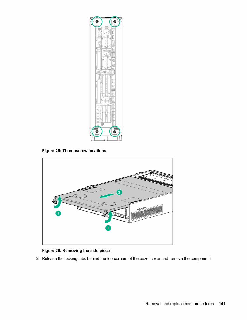
Figure 25: Thumbscrew locations
Figure 26: Removing the side piece
3. Release the locking tabs behind the top corners of the bezel cover and remove the component.
Removal and replacement procedures 141
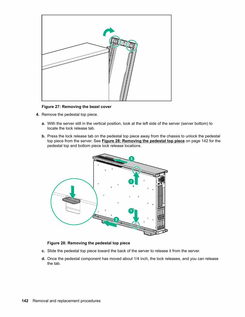
Figure 27: Removing the bezel cover
4. Remove the pedestal top piece.
a. With the server still in the vertical position, look at the left side of the server (server bottom) tolocate the lock release tab.
b. Press the lock release tab on the pedestal top piece away from the chassis to unlock the pedestaltop piece from the server. See Figure 28: Removing the pedestal top piece on page 142 for thepedestal top and bottom piece lock release locations.
Figure 28: Removing the pedestal top piece
c. Slide the pedestal top piece toward the back of the server to release it from the server.
d. Once the pedestal component has moved about 1/4 inch, the lock releases, and you can releasethe tab.
142 Removal and replacement procedures

e. Pull the pedestal kit top piece away from the server.
f. Repeat these steps for the bottom piece.
Access the product rear panel
Cable management arm with left-hand swing
Procedure
1. Remove the cable arm retainer.
2. Open the cable management arm.
Access the product rear panel 143
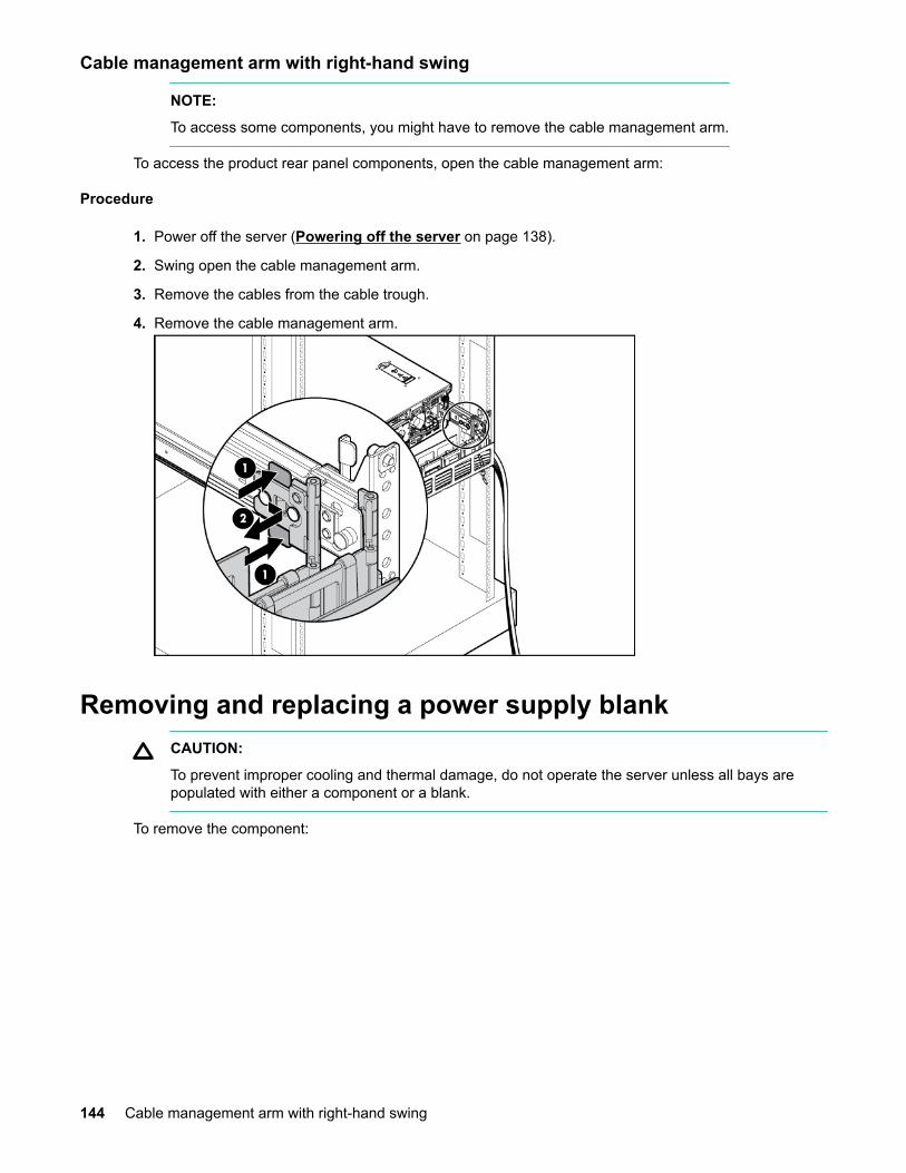
Cable management arm with right-hand swing
NOTE:
To access some components, you might have to remove the cable management arm.
To access the product rear panel components, open the cable management arm:
Procedure
1. Power off the server (Powering off the server on page 138).
2. Swing open the cable management arm.
3. Remove the cables from the cable trough.
4. Remove the cable management arm.
Removing and replacing a power supply blankCAUTION:
To prevent improper cooling and thermal damage, do not operate the server unless all bays arepopulated with either a component or a blank.
To remove the component:
144 Cable management arm with right-hand swing

Figure 29: Removing the blank
To replace the component, reverse the removal procedure.
Removing and replacing a hot-plug SAS hard driveThe server supports up to eight SFF, 2.5-inch SAS hard drives. Each drive is equipped with two LEDs thatindicate activity and device status.
To remove the component:
CAUTION:
For proper cooling do not operate the server without the access panel, baffles, expansion slotcovers, or blanks installed. If the server supports hot-plug components, minimize the amount of timethe access panel is open.
Procedure
1. Determine the status of the hard drive from the hot-plug SAS hard drive LED combinations.
2. Back up all server data on the hard drive.
3. Remove the hard drive.
To replace the component, see Installing a hot-pluggable SAS hard drive.
Removing and replacing a hot-plug SAS hard drive 145

Removing and replacing a power supply blankCAUTION:
To prevent improper cooling and thermal damage, do not operate the server unless all bays arepopulated with either a component or a blank.
To remove the component:
Figure 30: Removing the blank
To replace the component, reverse the removal procedure.
Removing and replacing a hot-swap power supplyThe server supports 1+1 redundant power supply for high line (1200W/200~240VAC) and low line (800W/100~120VAC) in the data center and office-friendly server versions.
Table 44: Power redundancy configurations
Line voltage Power supplycount
Processor count DIMM count Redundancy
High Line(200-240)
1 1 or 2 2 to 24 No
High Line(200-240)
2 1 or 2 2 to 24 Yes
Low Line (100-120) 1 1 or 2 2 to 12 No
Low Line (100-120) 2 1 2 to 12 Yes
Low Line (100-120) 2 2 2 to 8 1 Yes
1 A maximum of 8 DIMMs are supported in a configuration with low line AC voltage and 2 processors.
146 Removing and replacing a power supply blank
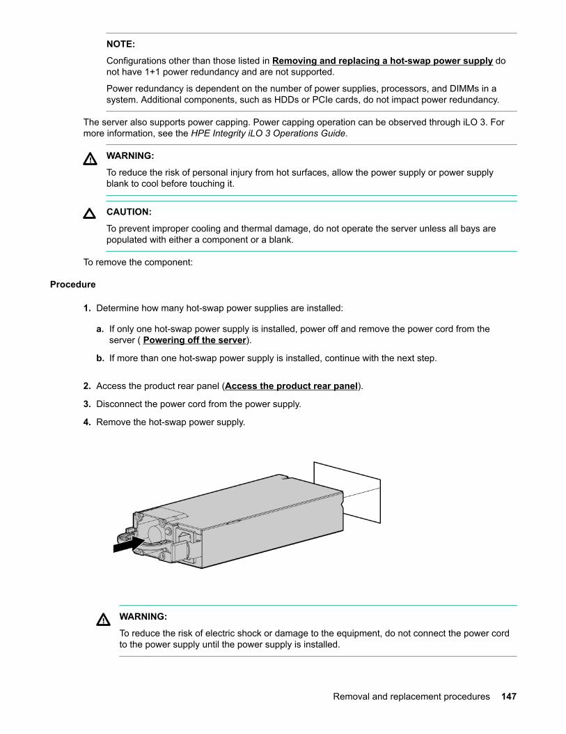
NOTE:
Configurations other than those listed in Removing and replacing a hot-swap power supply donot have 1+1 power redundancy and are not supported.
Power redundancy is dependent on the number of power supplies, processors, and DIMMs in asystem. Additional components, such as HDDs or PCIe cards, do not impact power redundancy.
The server also supports power capping. Power capping operation can be observed through iLO 3. Formore information, see the HPE Integrity iLO 3 Operations Guide.
WARNING:
To reduce the risk of personal injury from hot surfaces, allow the power supply or power supplyblank to cool before touching it.
CAUTION:
To prevent improper cooling and thermal damage, do not operate the server unless all bays arepopulated with either a component or a blank.
To remove the component:
Procedure
1. Determine how many hot-swap power supplies are installed:
a. If only one hot-swap power supply is installed, power off and remove the power cord from theserver ( Powering off the server).
b. If more than one hot-swap power supply is installed, continue with the next step.
2. Access the product rear panel (Access the product rear panel).
3. Disconnect the power cord from the power supply.
4. Remove the hot-swap power supply.
WARNING:
To reduce the risk of electric shock or damage to the equipment, do not connect the power cordto the power supply until the power supply is installed.
Removal and replacement procedures 147
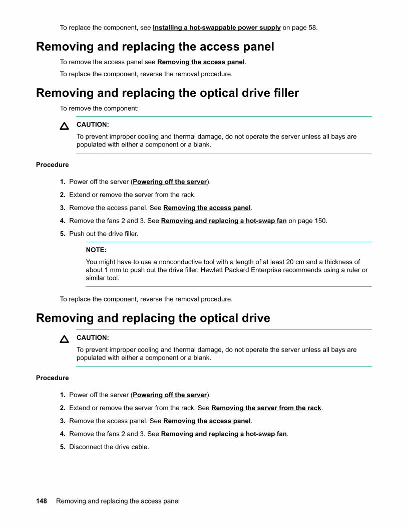
To replace the component, see Installing a hot-swappable power supply on page 58.
Removing and replacing the access panelTo remove the access panel see Removing the access panel.
To replace the component, reverse the removal procedure.
Removing and replacing the optical drive fillerTo remove the component:
CAUTION:
To prevent improper cooling and thermal damage, do not operate the server unless all bays arepopulated with either a component or a blank.
Procedure
1. Power off the server (Powering off the server).
2. Extend or remove the server from the rack.
3. Remove the access panel. See Removing the access panel.
4. Remove the fans 2 and 3. See Removing and replacing a hot-swap fan on page 150.
5. Push out the drive filler.
NOTE:
You might have to use a nonconductive tool with a length of at least 20 cm and a thickness ofabout 1 mm to push out the drive filler. Hewlett Packard Enterprise recommends using a ruler orsimilar tool.
To replace the component, reverse the removal procedure.
Removing and replacing the optical driveCAUTION:
To prevent improper cooling and thermal damage, do not operate the server unless all bays arepopulated with either a component or a blank.
Procedure
1. Power off the server (Powering off the server).
2. Extend or remove the server from the rack. See Removing the server from the rack.
3. Remove the access panel. See Removing the access panel.
4. Remove the fans 2 and 3. See Removing and replacing a hot-swap fan.
5. Disconnect the drive cable.
148 Removing and replacing the access panel

6. Lift the DVD release tab, and push out the drive. Then pull the drive straight out to remove it from theserver.
To replace the component, reverse the removal procedure.
Removal and replacement procedures 149

The optical drive cable routes beneath fan 2.
Removing and replacing a hot-swap fanSix fans cool the server. The fans are all redundant, hot-swappable, and interchangeable. If one fan unitfails, then the other fans increase speed to compensate. The fan units are N+1 redundant, meaning thatthe server has six fan units, but can operate with five fan units running.
CAUTION:
If more than one fan is removed or fails, the system does not shut down.
If the temperature sensors detect conditions outside of operating limits, the system shuts down.
Figure 31: Fan identification
The power supplies have built-in fans and are not controlled by the iLO MP.
For fan identification, see Figure 31: Fan identification on page 150.
150 Removing and replacing a hot-swap fan

Procedure
1. Extend or remove the server from the rack (Removing the server from the rack on page 139 or Extending the server from the rack).
2. Remove the access panel (Removing and replacing the access panel on page 148).
3. Remove the fan.
CAUTION:
Do not operate the server for long periods with the access panel open or removed. Operating theserver in this manner results in improper airflow and improper cooling that can lead to thermaldamage.
To replace the component, reverse the removal procedure.
Removing and replacing the power supply backplaneProcedure
1. Power off the server (Powering off the server).
2. Remove all power supplies (Removing and replacing a hot-swap power supply on page 146).
3. Extend or remove the server from the rack (Removing the server from the rack on page 139) or Extending the server from the rack).
4. Remove the access panel (Removing the access panel).
5. Remove the PCI cage (Removing the PCI riser cage).
6. Remove the necessary memory expansion boards (Installing DIMMs on page 67).
7. Remove the power supply backplane.
Removing and replacing the power supply backplane 151
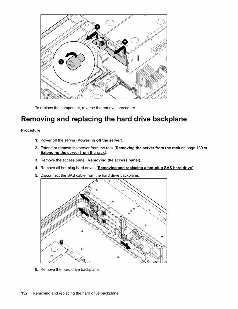
To replace the component, reverse the removal procedure.
Removing and replacing the hard drive backplaneProcedure
1. Power off the server (Powering off the server).
2. Extend or remove the server from the rack (Removing the server from the rack on page 139 or Extending the server from the rack).
3. Remove the access panel (Removing the access panel).
4. Remove all hot-plug hard drives (Removing and replacing a hot-plug SAS hard drive).
5. Disconnect the SAS cable from the hard drive backplane.
6. Remove the hard drive backplane.
152 Removing and replacing the hard drive backplane
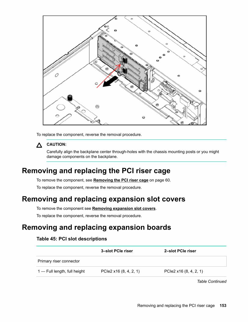
To replace the component, reverse the removal procedure.
CAUTION:
Carefully align the backplane center through-holes with the chassis mounting posts or you mightdamage components on the backplane.
Removing and replacing the PCI riser cageTo remove the component, see Removing the PCI riser cage on page 60.
To replace the component, reverse the removal procedure.
Removing and replacing expansion slot coversTo remove the component see Removing expansion slot covers.
To replace the component, reverse the removal procedure.
Removing and replacing expansion boardsTable 45: PCI slot descriptions
3–slot PCIe riser 2–slot PCIe riser
Primary riser connector
1 — Full length, full height PCIe2 x16 (8, 4, 2, 1) PCIe2 x16 (8, 4, 2, 1)
Table Continued
Removing and replacing the PCI riser cage 153
3–slot PCIe riser 2–slot PCIe riser
2 — Half length, full height PCIe2 x8 (4, 2, 1) PCIe2 x16 (8, 4, 2, 1)
3 — Half length, full height PCIe2 x8 (4, 2, 1) —
Secondary riser connector
4 — Full length, full height PCIe2 x16 (8, 4, 2, 1) PCIe2 x16 (8, 4, 2, 1)
5 — Low profile PCIe2 x8 (4, 2, 1) PCIe2 x16 (8, 4, 2, 1)
6 — Low profile PCIe2 x8 (4, 2, 1) —
The server supports up to two PCIe riser boards. Each PCIe riser board holds up to three PCIe cardseach. The standard riser board configuration contains one riser board with one full-length, full-height PCIex8 slot, and two half-length, full-height PCIe x4 slots. The second board contains one full-length, full-height PCIe x8 slot, and two half-length, half-height PCIe x4 slots.
The optional riser board configuration contains one riser board with one full-length, full-height PCIe x8slot, and two half-length, full-height PCIe x4 slots. The second board contains one full-length, full-heightPCIe x16 slot.
Removing and replacing a half-length expansion board
Procedure
1. Power off the server (Powering off the server on page 138).
2. Extend the server from the rack (Extending the server from the rack on page 134).
3. Remove the access panel (Removing and replacing the access panel).
4. Disconnect any external cables that are connected to the expansion board.
5. Remove the PCI riser cage (Removing and replacing the PCI riser cage on page 153).
6. Disconnect any internal cables that are connected to the expansion board.
7. Remove expansion board.
154 Removing and replacing a half-length expansion board
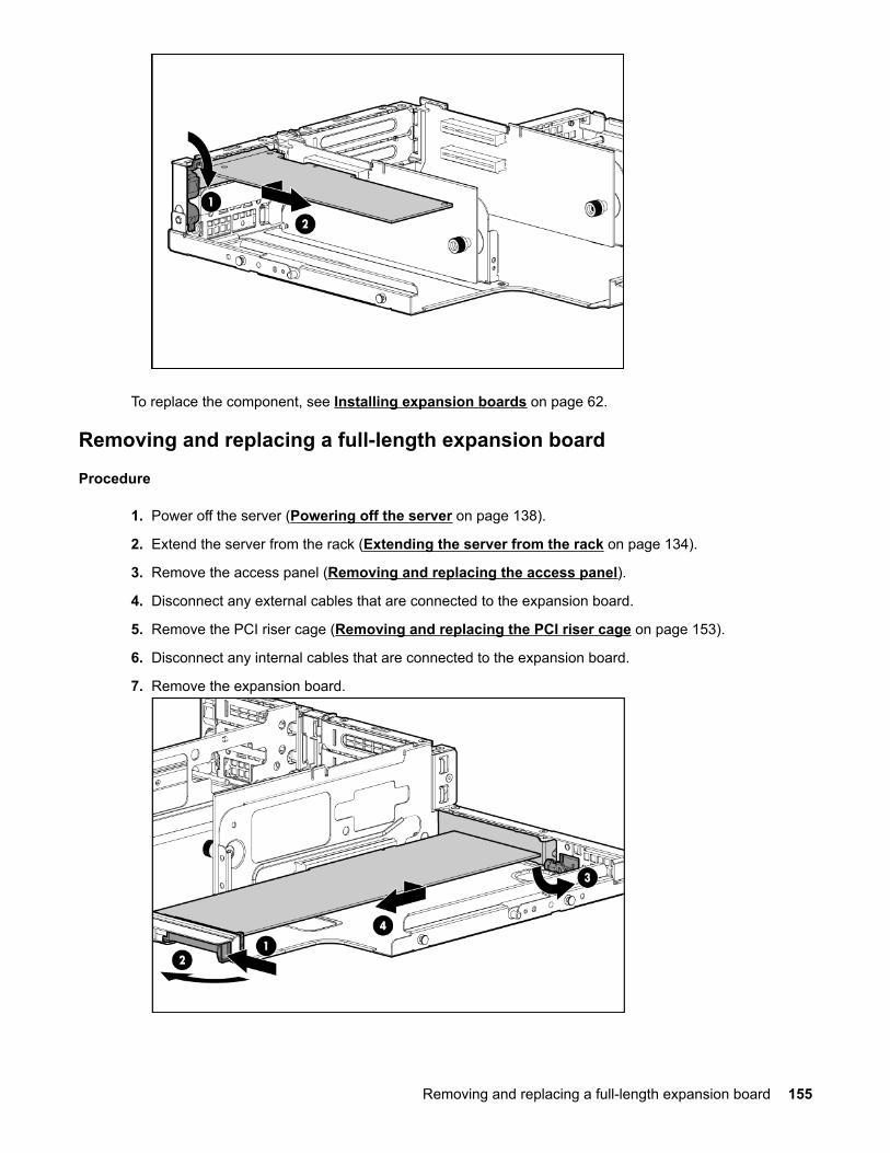
To replace the component, see Installing expansion boards on page 62.
Removing and replacing a full-length expansion board
Procedure
1. Power off the server (Powering off the server on page 138).
2. Extend the server from the rack (Extending the server from the rack on page 134).
3. Remove the access panel (Removing and replacing the access panel).
4. Disconnect any external cables that are connected to the expansion board.
5. Remove the PCI riser cage (Removing and replacing the PCI riser cage on page 153).
6. Disconnect any internal cables that are connected to the expansion board.
7. Remove the expansion board.
Removing and replacing a full-length expansion board 155

To replace the component, see Installing expansion boards on page 62.
Removing and replacing the cache moduleNOTE:
The cache module is required to enable the full feature firmware stack for RAID support, and certainlevels of RAID support also require the super capacitor module and a Advanced Pack license key.
To enable Advanced Pack licensing, see Adding a RAID Advanced Pack license key on page185.
Procedure
1. Power off the server (Powering off the server).
2. Extend or remove the server from the rack (Removing the server from the rack on page 139) or Extending the server from the rack).
3. Remove the access panel (Removing and replacing the access panel on page 148).
4. Remove the PCI riser cage (Removing the PCI riser cage).
5. Disconnect the cable to the super capacitor pack.
6. Remove the cache module.
156 Removing and replacing the cache module
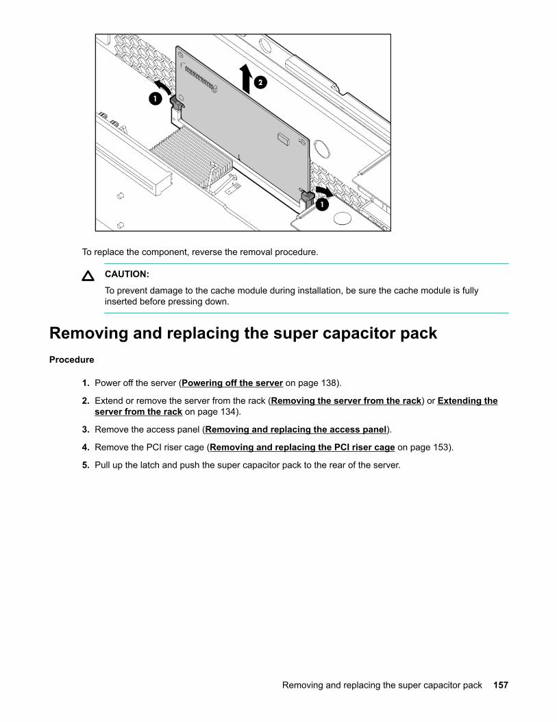
To replace the component, reverse the removal procedure.
CAUTION:
To prevent damage to the cache module during installation, be sure the cache module is fullyinserted before pressing down.
Removing and replacing the super capacitor packProcedure
1. Power off the server (Powering off the server on page 138).
2. Extend or remove the server from the rack (Removing the server from the rack) or Extending theserver from the rack on page 134).
3. Remove the access panel (Removing and replacing the access panel).
4. Remove the PCI riser cage (Removing and replacing the PCI riser cage on page 153).
5. Pull up the latch and push the super capacitor pack to the rear of the server.
Removing and replacing the super capacitor pack 157
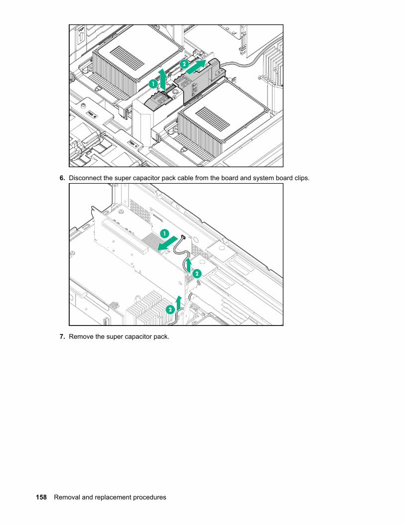
6. Disconnect the super capacitor pack cable from the board and system board clips.
7. Remove the super capacitor pack.
158 Removal and replacement procedures
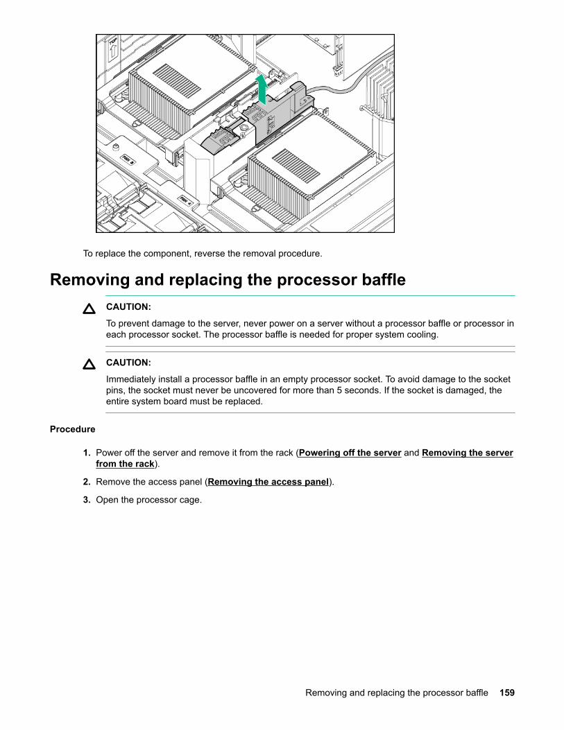
To replace the component, reverse the removal procedure.
Removing and replacing the processor baffleCAUTION:
To prevent damage to the server, never power on a server without a processor baffle or processor ineach processor socket. The processor baffle is needed for proper system cooling.
CAUTION:
Immediately install a processor baffle in an empty processor socket. To avoid damage to the socketpins, the socket must never be uncovered for more than 5 seconds. If the socket is damaged, theentire system board must be replaced.
Procedure
1. Power off the server and remove it from the rack (Powering off the server and Removing the serverfrom the rack).
2. Remove the access panel (Removing the access panel).
3. Open the processor cage.
Removing and replacing the processor baffle 159
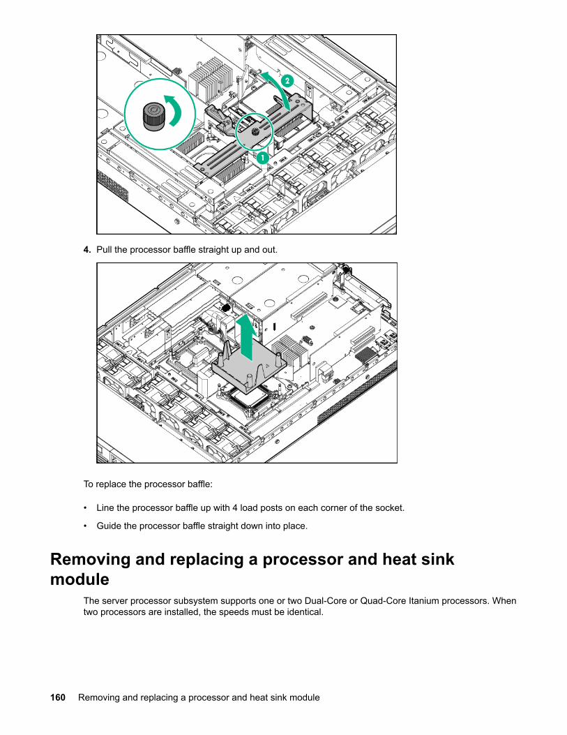
4. Pull the processor baffle straight up and out.
To replace the processor baffle:
• Line the processor baffle up with 4 load posts on each corner of the socket.
• Guide the processor baffle straight down into place.
Removing and replacing a processor and heat sinkmodule
The server processor subsystem supports one or two Dual-Core or Quad-Core Itanium processors. Whentwo processors are installed, the speeds must be identical.
160 Removing and replacing a processor and heat sink module
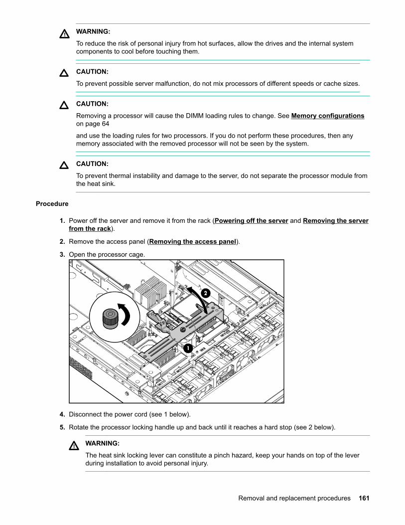
WARNING:
To reduce the risk of personal injury from hot surfaces, allow the drives and the internal systemcomponents to cool before touching them.
CAUTION:
To prevent possible server malfunction, do not mix processors of different speeds or cache sizes.
CAUTION:
Removing a processor will cause the DIMM loading rules to change. See Memory configurationson page 64
and use the loading rules for two processors. If you do not perform these procedures, then anymemory associated with the removed processor will not be seen by the system.
CAUTION:
To prevent thermal instability and damage to the server, do not separate the processor module fromthe heat sink.
Procedure
1. Power off the server and remove it from the rack (Powering off the server and Removing the serverfrom the rack).
2. Remove the access panel (Removing the access panel).
3. Open the processor cage.
4. Disconnect the power cord (see 1 below).
5. Rotate the processor locking handle up and back until it reaches a hard stop (see 2 below).
WARNING:
The heat sink locking lever can constitute a pinch hazard, keep your hands on top of the leverduring installation to avoid personal injury.
Removal and replacement procedures 161
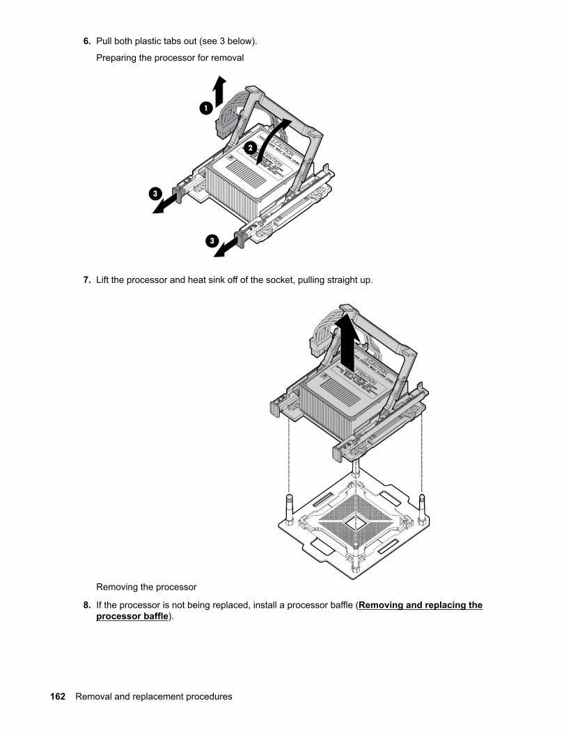
6. Pull both plastic tabs out (see 3 below).
Preparing the processor for removal
7. Lift the processor and heat sink off of the socket, pulling straight up.
Removing the processor
8. If the processor is not being replaced, install a processor baffle (Removing and replacing theprocessor baffle).
162 Removal and replacement procedures

CAUTION:
To avoid damage to processor socket pins and ensure proper system cooling, install a processorbaffle in an empty processor socket.
To replace a processor that is not defective, reverse the removal procedure.
The replacement processor module is shipped from Hewlett Packard Enterprise without a heat sink. Youwill need to order and attach a heat sink to the processor module before installing them for repair.
Refer to Installing a processor and heat sink module on page 69 for more information on theinstallation procedure.
WARNING:DO NOT SEPARATE THE HEATSINK FROM THE PROCESSOR MODULE.
Damage to the assembly will occur! Only Factory-Repair is authorized to separate assembly.
Return the assembly in the heatsink box using the processor's defective return label.
When the processor/heatsink assembly is removed from the server:
• Do NOT separate the heatsink from the processor.
• Place the intact processor/heatsink assembly, with the handle in the up position , into theextra ESD bag provided in the heatsink box (if necessary re-use the ESD bag from the processorbox).
• To receive credit for both the processor and the heatsink:
◦ Package the processor/heatsink assembly into the
heatsink box.
◦ Place the paper work originally shipped with the processor in the heatsink box.
◦ Apply the processor defective return label to the heatsink box.
Global Customer Services and Support (GCSS) case coding recommendations:
• If the new processor/heatsink assembly is used – (solves the issue or is left in the server for anyreason) – return the defective assembly using the normal process; for example a part failurecode of 74, 75, etc…
• Once assembled, the parts cannot be returned as “Unused” .
In some scenarios assembled parts will not fix an issue, for example:
◦ The new assembly is removed and the original is re-installed in the server.
◦ The wrong speed processor or heatsink combination is assembled.
In these cases:
◦ Use the defective label (B label) from the processor box and apply to the heatsink box.
◦ Use a Parts Failure Code of “AI” on both parts.
Removal and replacement procedures 163

NOTE: After replacing the processor and heat sink module use the cpuconfig from UEFI to verifythe that the processor socket has been reconfigured.
Removing and replacing DIMMsThe server supports up to 24 memory DIMMs that attach to the system board through 4 memoryexpansion board boards (6 DIMMs per board). The minimum amount of memory supported is 4 GB (two 2GB DIMMs). The maximum memory supported is 384 GB (twenty-four 16 GB DIMMs). The supportedDIMMs are industry-standard, 30 mm (1.18 inch) high, DDR3 PC3 DIMMs. The server does not supporthot-spare and hot-plug functionality.
The server supports the following DIMM sizes:
• 2 GB
• 4 GB
• 8 GB
• 16 GB
For memory configurations see Installing DIMMs.
Procedure
1. Power off the server (Powering off the server).
2. Extend or remove the server from the rack (Removing the server from the rack on page 139 or Extending the server from the rack).
3. Remove the access panel (Removing the access panel).
4. Remove the memory expansion board.
164 Removing and replacing DIMMs
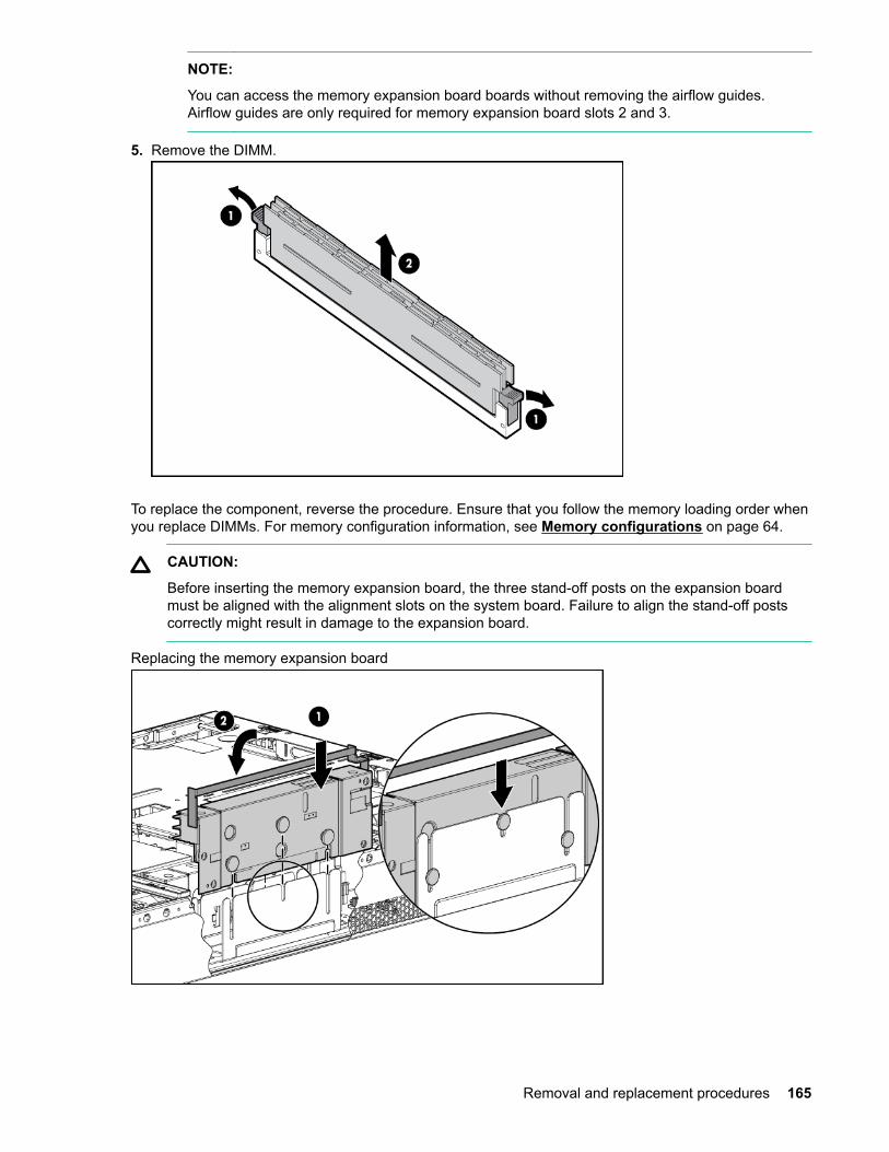
NOTE:
You can access the memory expansion board boards without removing the airflow guides.Airflow guides are only required for memory expansion board slots 2 and 3.
5. Remove the DIMM.
To replace the component, reverse the procedure. Ensure that you follow the memory loading order whenyou replace DIMMs. For memory configuration information, see Memory configurations on page 64.
CAUTION:
Before inserting the memory expansion board, the three stand-off posts on the expansion boardmust be aligned with the alignment slots on the system board. Failure to align the stand-off postscorrectly might result in damage to the expansion board.
Replacing the memory expansion board
Removal and replacement procedures 165

Removing and replacing the PDH battery (system battery)If the server no longer automatically displays the correct date and time, you might have to replace thebattery that provides power to the real-time clock.
WARNING:
The computer contains an internal lithium manganese dioxide, a vanadium pentoxide, or an alkalinebattery pack. If the battery pack is not properly handled, a risk of fire and burns exists. To reduce therisk of personal injury:
• Do not attempt to recharge the battery.
• Do not expose the battery to temperatures higher than 60°C (140°F).
• Do not disassemble, crush, puncture, short external contacts, or dispose of in fire or water.
• Replace only with the spare designated for this product.
Procedure
1. Power off the server (Powering off the server).
2. Extend the server from the rack (Extending the server from the rack).
3. Remove the access panel (Removing the access panel).
4. Remove the PCI riser cage (Removing the PCI riser cage).
WARNING:
Do not attempt to remove the battery by hand. Doing so can cause the battery holder to separatefrom the system board.
WARNING:
Do not attempt to remove the battery from the side marked “+” first. If your battery holder doesnot have the “+” marking, the side of the holder with springs will be the “+” end.
5. Using a nonconductive tool small enough to fit into the battery slot as leverage, gently remove thebattery from the holder from the end marked “---“.
NOTE:
Hewlett Packard Enterprise recommends using ESD safe, non-conductive tweezers or a similartool.
To replace the component, reverse the removal procedure.
IMPORTANT:
Ensure that the new battery is fully seated and that all locking tabs are correctly engaged.
166 Removing and replacing the PDH battery (system battery)

Removing the system battery
For more information about battery replacement or proper disposal, contact an authorized reseller or anauthorized service provider.
Removing and replacing the SIDProcedure
1. Power off the server (Powering off the server).
2. Extend the server from the rack (Extending the server from the rack).
3. Remove the access panel (Removing the access panel).
4. Remove necessary fans 1 and 2.
5. Remove the screw securing the SID inside the chassis.
6. Disconnect the cable clip.
7. Pull the Systems Insight Display module halfway out of the server.
8. Disconnect the Systems Insight Display cable.
9. Remove the Systems Insight Display module.
Removing and replacing the SID 167

To replace the component, reverse the removal procedure.
If installing a replacement SID module:
• Retain the SID bezel, the transparent light pipe, and the black rubber light pipe.
• Install the transparent plastic light pipe onto the SID bezel.
• Install the SID bezel onto the metal chassis, ensuring the four latches all lock.
• Put the black rubber light pipe onto the plastic light pipe.
168 Removal and replacement procedures
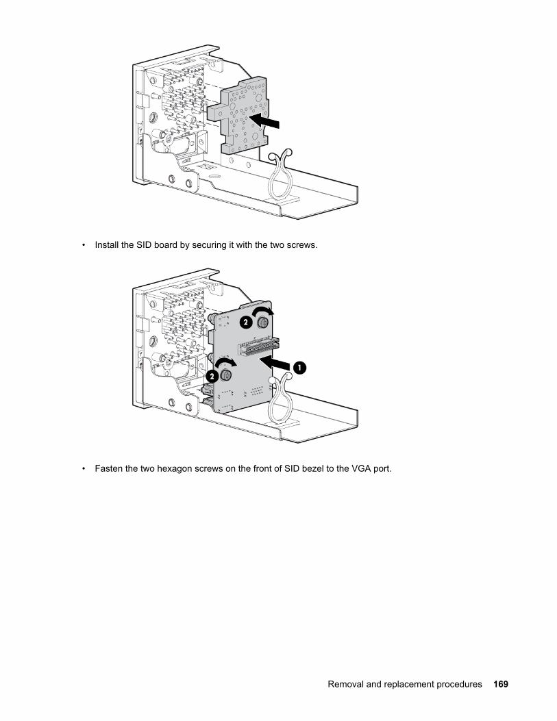
• Install the SID board by securing it with the two screws.
• Fasten the two hexagon screws on the front of SID bezel to the VGA port.
Removal and replacement procedures 169
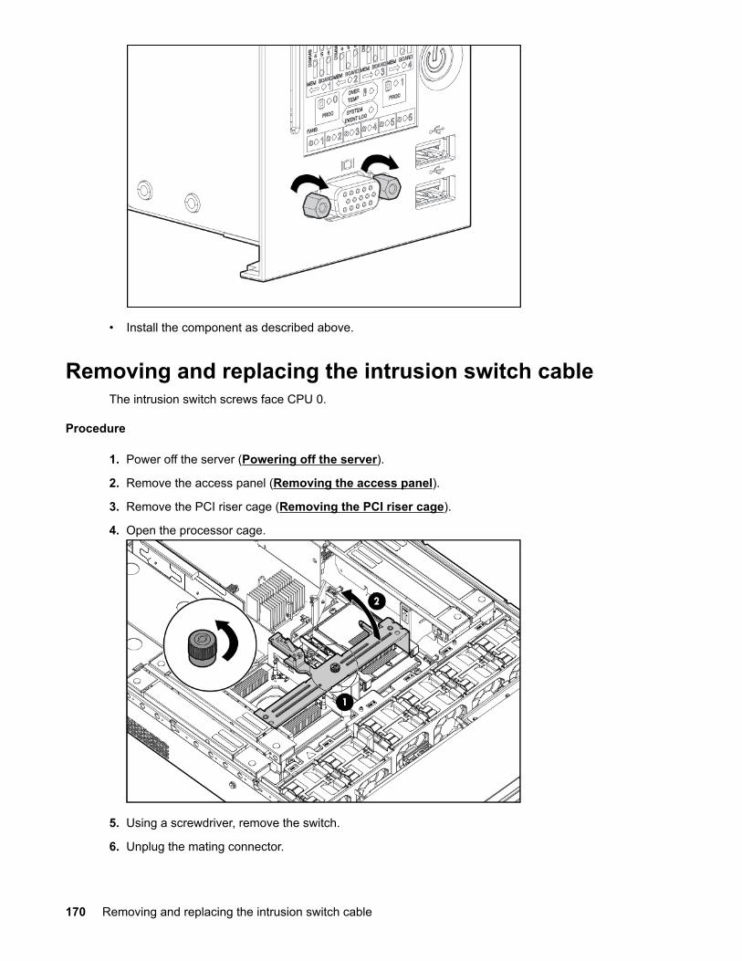
• Install the component as described above.
Removing and replacing the intrusion switch cableThe intrusion switch screws face CPU 0.
Procedure
1. Power off the server (Powering off the server).
2. Remove the access panel (Removing the access panel).
3. Remove the PCI riser cage (Removing the PCI riser cage).
4. Open the processor cage.
5. Using a screwdriver, remove the switch.
6. Unplug the mating connector.
170 Removing and replacing the intrusion switch cable

To replace the component, reverse the removal procedure.
Removing and replacing the system boardIMPORTANT:
If your system board has a TPM installed, you must order a new TPM when you order areplacement system board.
Before replacing the system board, you must first back up the current TPM settings. See the HP-UXoperating system documentation for more information.
The TPM is not a customer-installable component. If you need to replace a TPM on a replacementsystem board, contact a Hewlett Packard Enterprise authorized service provider.
WARNING:
Once the TPM is installed on your system board, it cannot be removed. If the TPM fails, the systemboard needs to be replaced. Attempting to remove the TPM from the system board will void anyexisting Hewlett Packard Enterprise service contract and cause the server to fail.
Procedure
1. Power off the server (Powering off the server).
2. Remove all power supplies (Removing and replacing a hot-swap power supply on page 146).
3. Remove all hot-plug hard drives (Removing and replacing a hot-plug SAS hard drive).
4. Extend or remove the server from the rack (Removing the server from the rack on page 139) or Extending the server from the rack).
5. Remove the access panel (Removing the access panel).
6. Remove the air baffle.
Removing and replacing the system board 171
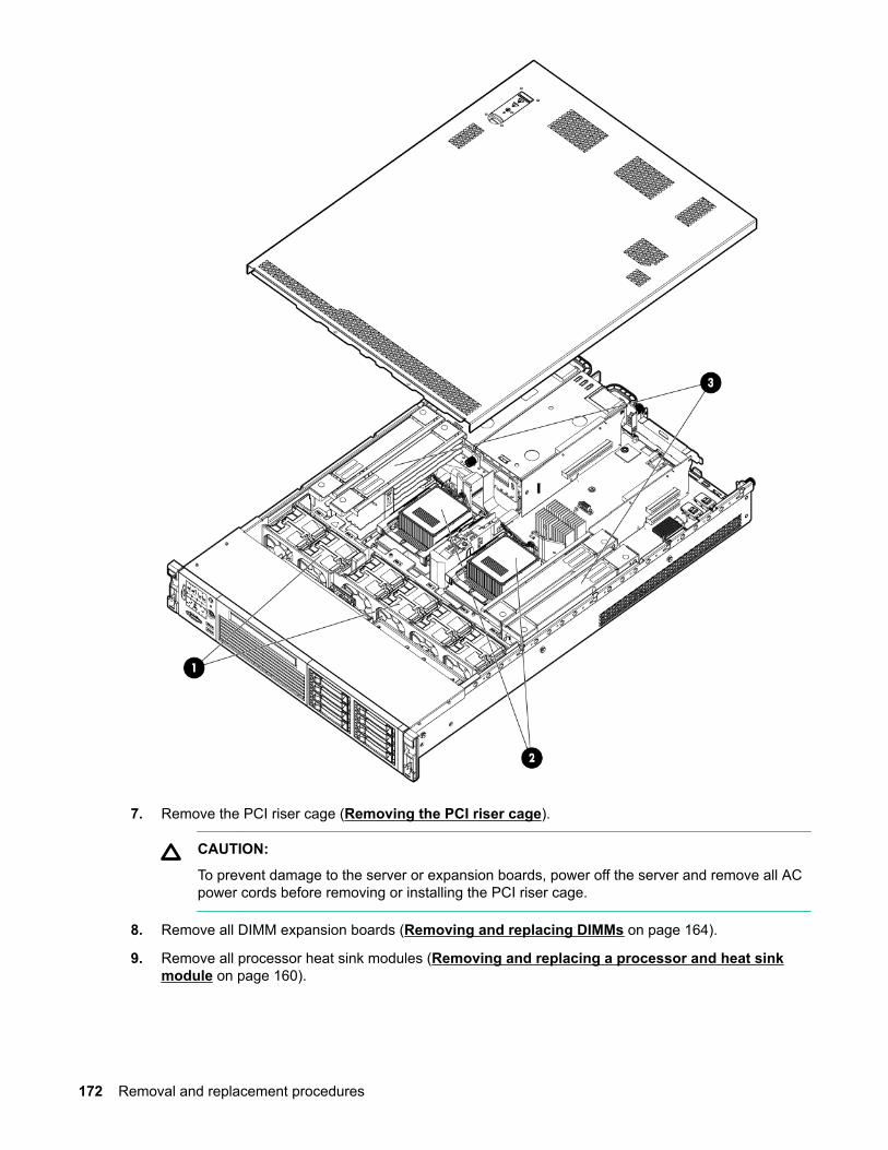
7. Remove the PCI riser cage (Removing the PCI riser cage).
CAUTION:
To prevent damage to the server or expansion boards, power off the server and remove all ACpower cords before removing or installing the PCI riser cage.
8. Remove all DIMM expansion boards (Removing and replacing DIMMs on page 164).
9. Remove all processor heat sink modules (Removing and replacing a processor and heat sinkmodule on page 160).
172 Removal and replacement procedures
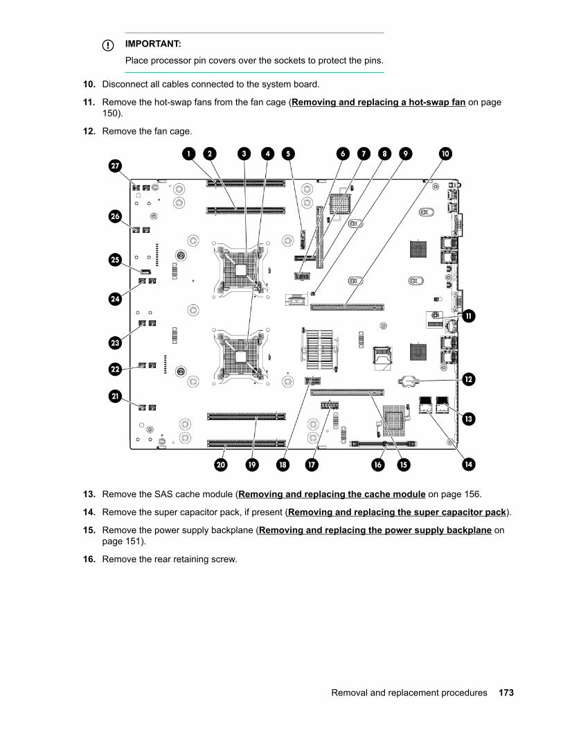
IMPORTANT:
Place processor pin covers over the sockets to protect the pins.
10. Disconnect all cables connected to the system board.
11. Remove the hot-swap fans from the fan cage (Removing and replacing a hot-swap fan on page150).
12. Remove the fan cage.
13. Remove the SAS cache module (Removing and replacing the cache module on page 156.
14. Remove the super capacitor pack, if present (Removing and replacing the super capacitor pack).
15. Remove the power supply backplane (Removing and replacing the power supply backplane onpage 151).
16. Remove the rear retaining screw.
Removal and replacement procedures 173
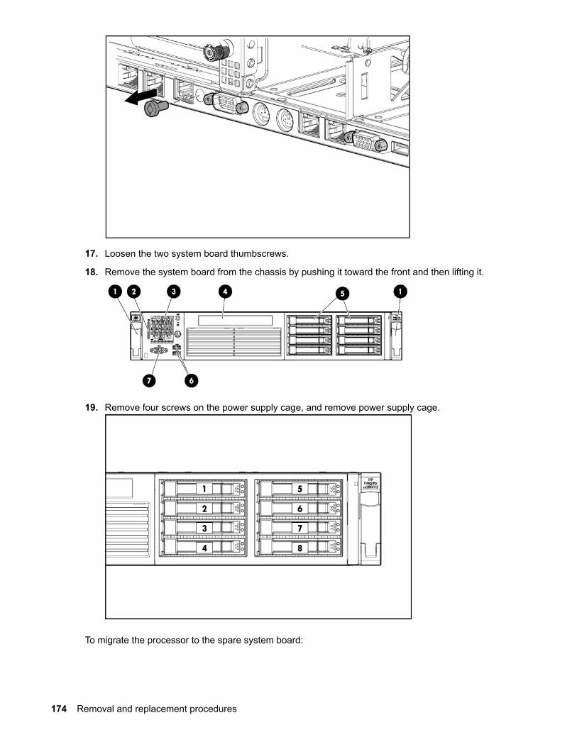
17. Loosen the two system board thumbscrews.
18. Remove the system board from the chassis by pushing it toward the front and then lifting it.
19. Remove four screws on the power supply cage, and remove power supply cage.
To migrate the processor to the spare system board:
174 Removal and replacement procedures

• Take the iLO label off the system board information label and place it over the iLO information pull tabon the front panel.
• Install the spare system board.
• Remove the battery insulator strip from the system board battery.
• Install the processors and heat sink or processor heat sink module the system board (Installing aprocessor on page 68).
• Install all components removed from the failed system board.
• Install the access panel (Removing and replacing the access panel on page 148).
• Install the power supplies (Removing and replacing a hot-swap power supply on page 146).
• Power up the server.
CAUTION:Replacement system boards are shipped with the RAID controller in HBA mode by default. Whenthe original components are re-installed on the replacement board and the system is booted toUEFI, the saupdate utility must be used to re-enable the RAID configuration if the original serverwas using the RAID functionality. See SAS disk setup for instructions on using the saupdateutility.
After you replace the system board, you must to set the SAS mode to RAID if that was your previousconfiguration.
• During the server startup, wait for UEFI Front Page, press S to launch the UEFI Shell.
• Get the saupdate.efi utility tool.
• Enter saupdate.efi set_mode 0:1:0:0 raid to change the SAS mode to RAID.
• Enter saupdate.efi get_mode 0:1:0:0 to verify the SAS mode is set to RAID.
After you replace the system board, you must port over the server serial number, product number andUUID. Labels on the server indicates these numbers.
• Log in to iLO 3 MP, by using SSH, for example.
• Access the MP Main Menu.
• Enter CM at the hpiLO-> prompt.
• Enter sysset at the CM:hpiLO> prompt, and it will show the system information.
• To change the serial number:
• a. Enter sysset -serial <serial number> at the CM:hpiLO-> prompt.
• b. Enter the associated password, and press Enter.
• To change product number (default is for the data center server):
• a. Enter sysset -prodnum <product number> at the CM:hpiLO-> prompt.
• b. Enter the associated password, and press Enter.
• To change the UUID:
• a. Enter sysset -uuid <uuid> at the MP:CM -> prompt.
Removal and replacement procedures 175

• b. Enter the associated password and press Enter
• Reset iLO MP by entering xd -r -nc at the CM:hpiLO-> prompt.
176 Removal and replacement procedures
Support and other resources
Accessing Hewlett Packard Enterprise Support• For live assistance, go to the Contact Hewlett Packard Enterprise Worldwide website:
www.hpe.com/assistance
• To access documentation and support services, go to the Hewlett Packard Enterprise Support Centerwebsite:
www.hpe.com/support/hpesc
Information to collect
• Technical support registration number (if applicable)
• Product name, model or version, and serial number
• Operating system name and version
• Firmware version
• Error messages
• Product-specific reports and logs
• Add-on products or components
• Third-party products or components
Accessing updates• Some software products provide a mechanism for accessing software updates through the product
interface. Review your product documentation to identify the recommended software update method.
• To download product updates, go to either of the following:
◦ Hewlett Packard Enterprise Support Center Get connected with updates page:
www.hpe.com/support/e-updates
◦ Software Depot website:
www.hpe.com/support/softwaredepot
• To view and update your entitlements, and to link your contracts and warranties with your profile, go tothe Hewlett Packard Enterprise Support Center More Information on Access to Support Materialspage:
www.hpe.com/support/AccessToSupportMaterials
Support and other resources 177

IMPORTANT:
Access to some updates might require product entitlement when accessed through the HewlettPackard Enterprise Support Center. You must have an HP Passport set up with relevantentitlements.
WebsitesWebsite Link
Hewlett Packard Enterprise Information Library www.hpe.com/info/enterprise/docs
Hewlett Packard Enterprise Support Center www.hpe.com/support/hpesc
Contact Hewlett Packard Enterprise Worldwide www.hpe.com/assistance
Subscription Service/Support Alerts www.hpe.com/support/e-updates
Software Depot www.hpe.com/support/softwaredepot
Customer Self Repair www.hpe.com/support/selfrepair
Insight Remote Support www.hpe.com/info/insightremotesupport/docs
Serviceguard Solutions for HP-UX www.hpe.com/info/hpux-serviceguard-docs
Single Point of Connectivity Knowledge (SPOCK)Storage compatibility matrix
www.hpe.com/storage/spock
Storage white papers and analyst reports www.hpe.com/storage/whitepapers
Customer self repairHewlett Packard Enterprise customer self repair (CSR) programs allow you to repair your product. If aCSR part needs to be replaced, it will be shipped directly to you so that you can install it at yourconvenience. Some parts do not qualify for CSR. Your Hewlett Packard Enterprise authorized serviceprovider will determine whether a repair can be accomplished by CSR.
For more information about CSR, contact your local service provider or go to the CSR website:
www.hpe.com/support/selfrepair
Documentation feedbackHewlett Packard Enterprise is committed to providing documentation that meets your needs. To help usimprove the documentation, send any errors, suggestions, or comments to Documentation Feedback([email protected]). When submitting your feedback, include the document title, part number,edition, and publication date located on the front cover of the document. For online help content, includethe product name, product version, help edition, and publication date located on the legal notices page.
178 Websites

Standard terms, abbreviations and acronymsACPI
Advanced Configuration and Power Interface.
BBWC
Battery Backed Write Cache.
CMC
Corrected machine check.
Cold-swappable
A component that requires the operating system be shut down and the server powered off before itcan be removed. Cold-swappable components are signified with blue touch points.
CPE
Corrected platform error.
CRU
Customer Replaceable Unit.
DHCP
Dynamic Host Configuration Protocol.
DDNS
Dynamic DNS.
DMA
Direct memory access.
ESD
Electrostatic discharge.
FBWC
Flash Backed Write Cache.
FRU
Field Replaceable Unit.
HDD
Hard disk drive.
Hot-pluggable
A component that can be removed from the server while the server remains operational, but softwareintervention is required prior to removing the component. Hot-pluggable components are signified withred touch points.
Hot-swappable
A component that can be removed from the server while the server remains operational and requiresno software intervention prior to removing the component. Hot-swappable components are signifiedwith red touch points.
Standard terms, abbreviations and acronyms 179

iLO 3
Integrated Lights Out 3.
LOM
LAN-on-motherboard.
MAC
Media Access Control.
PAL
Processor Abstraction Layer.
PDT
Page deallocation table.
PE
Protective earthing.
RDIMM
Registered DIMM.
SAL
System Abstraction Layer.
SAS
Serial-attached SCSI.
SEL
System event log.
SFF
Small form factor.
SID
System Insight Display.
SFW
System firmware.
UEFI
Unified Extensible Firmware Interface.
UDIMM
Unbuffered DIMM.
UID
Unit identification.
WBEM
Web-Based Enterprise Management.
180 Standard terms, abbreviations and acronyms
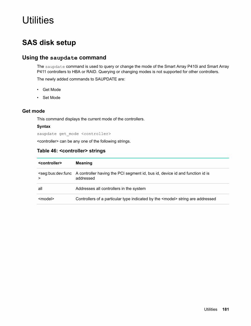
Utilities
SAS disk setup
Using the saupdate commandThe saupdate command is used to query or change the mode of the Smart Array P410i and Smart ArrayP411 controllers to HBA or RAID. Querying or changing modes is not supported for other controllers.
The newly added commands to SAUPDATE are:
• Get Mode
• Set Mode
Get modeThis command displays the current mode of the controllers.
Syntaxsaupdate get_mode <controller><controller> can be any one of the following strings.
Table 46: <controller> strings
<controller> Meaning
<seg:bus:dev:func>
A controller having the PCI segment id, bus id, device id and function id isaddressed
all Addresses all controllers in the system
<model> Controllers of a particular type indicated by the <model> string are addressed
Utilities 181
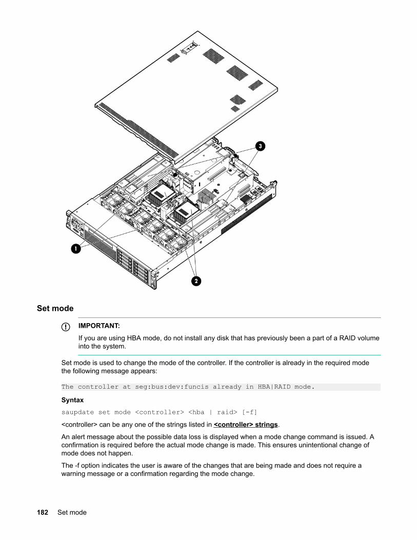
Set mode
IMPORTANT:
If you are using HBA mode, do not install any disk that has previously been a part of a RAID volumeinto the system.
Set mode is used to change the mode of the controller. If the controller is already in the required modethe following message appears:
The controller at seg:bus:dev:funcis already in HBA|RAID mode.Syntaxsaupdate set mode <controller> <hba | raid> [-f]<controller> can be any one of the strings listed in <controller> strings.
An alert message about the possible data loss is displayed when a mode change command is issued. Aconfirmation is required before the actual mode change is made. This ensures unintentional change ofmode does not happen.
The -f option indicates the user is aware of the changes that are being made and does not require awarning message or a confirmation regarding the mode change.
182 Set mode
IMPORTANT:
After changing the mode, perform a reconnect -r command at UEFI.
NOTE:
Commands are not case-sensitive.
Updating the firmware using saupdateProcedure
1. Download the firmware image file into the system UEFI partition.
2. Boot the system to the UEFI Shell and change directories to the UEFI partition.
3. Use the saupdate list to display all detected Smart Array controllers along with the active firmwareversions, the identification information from this list is used to designate which controller is to beupdated.
4. Use saupdate update <seg:bus:dev:func:index> <firmware image> to update thefirmware.
5. Restart the system.
To query the current mode of the controller usesaupdate get_mode <controller>. The <controller>could be any one of the strings:
• <seg:bus:dev:func>A controller having the PCI segment id, bus id, device id and function id is addressed
• all
Updating the firmware using saupdate 183

Addresses all controllers in the system
• <model>Controllers of a particular type indicated by the <model) string are addressed.
To change the mode of the controller use saupdate set_mode <controller> <hba | raid> [-f].
NOTE: A system reset or a reconnect-r is required after changing from HBA to RAID mode.
An alert message about the possible data loss is displayed when a mode change command is issued. Aconfirmation is required before the actual mode change is made. This ensures unintentional change ofmode does not happen.
The –f option indicates the user is aware of the changes that are being made and does not require awarning message or a confirmation regarding the mode change.
NOTE: Commands are not case-sensitive. A system reset or reconnect-r followed by map –r isrequired when changing from HBA mode to RAID mode.
Determining the Driver ID and CTRL IDUse the drvcfg utility and UEFI shell commands to find the Driver ID corresponding Ctrl ID for the SASHost Bus Adapter.
Procedure
1. At the UEFI shell, use the drivers command.
2. Find the SAS Host Bus Adapter in the list of drivers, and make a note of the Driver ID from the leftcolumn.
3. Use the drvcfg command.
4. Find the SAS Host Bus Adapter's Driver ID in the list, and make a note of the corresponding Ctrl ID.
Using the ORCA menu-driven interfaceFrom the UEFI Shell, enter drvcfg -s <Driver ID> <Ctrl ID>. The ORCA main menuappears.ORCA Main Menu
184 Determining the Driver ID and CTRL ID
The ORCA main menu contains the following options:
• Create Logical Drive
• View Logical Drive
• Delete Logical Drive
• Manage License Keys
Creating a logical drive
Procedure
1. At the ORCA main menu, select Create Logical Drive.
2. Select the physical disks to be included in the logical drive in the Available Physical Drives section.
3. To select the Raid Configurations section and select the RAID type for the logical drive, press Tab.
4. To select the Spare section and assign spare disks, as needed, press Tab.
5. To create the logical drive, press Enter. A summary of your choices appears.
6. To save the configuration, press F8.
7. If the function keys are disabled, press Esc and then press 8.
8. To acknowledge that the configuration was saved and return to the ORCA Main Menu, press Enter.
Deleting a logical drive
WARNING:
Back up all necessary data before deleting the logical drive. When you delete a logical drive, dataon the drive is not preserved.
Procedure
1. At the ORCA main menu, select Delete Logical Drive.
2. Select a logical drive to be deleted.
3. Press F3 to delete the logical drive.
4. If the function keys are disabled, press Esc and then press 3.
5. To acknowledge that the configuration was saved and return to the ORCA Main Menu, press Enter.
Adding a RAID Advanced Pack license key
Procedure
1. At the ORCA main menu, select Manage License Keys.
Creating a logical drive 185
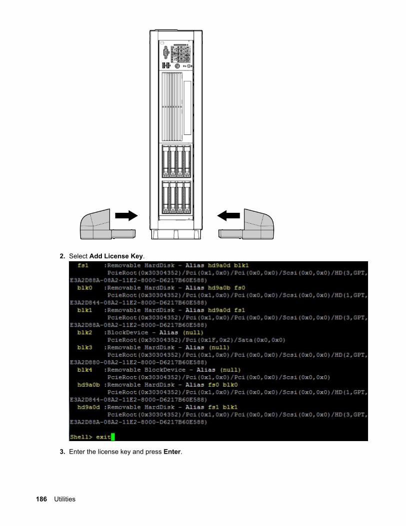
2. Select Add License Key.
3. Enter the license key and press Enter.
186 Utilities

4. Verify your license key. See Viewing RAID advanced pack license keys on page 187.
Viewing RAID advanced pack license keys
Procedure
1. At the ORCA main menu, select Manage License Keys.
2. Select View License Key(s).
3. All advanced pack license keys are displayed. Press Esc to return to the License Keys Menu.
UEFIUEFI is an OS and platform-independent boot and preboot interface. UEFI resides between the OS andplatform firmware, enabling the OS to boot without having details about the underlying hardware andfirmware. UEFI supports boot devices, uses a flat memory model, and hides platform and firmware detailsfrom the OS.
NOTE:
Unified UEFI Forum, Inc. defines the specification used to implement UEFI. POSSE is a HewlettPackard Enterprise extension to UEFI, which provides a common user interface architecture tobetter serve Hewlett Packard Enterprise customers, service, and manufacturing.
UEFI consolidates boot utilities similar to those found in PA-RISC based servers, such as the BCH, andplatform firmware into a single platform firmware. UEFI enables the selection of any UEFI OS loader fromany boot medium that is supported by UEFI boot services. An UEFI OS loader supports multiple optionson the user interface.
UEFI supports booting from media that contain an UEFI OS loader or an UEFI-defined server partition.An UEFI-defined system partition is required by UEFI to boot from a block device.
The UEFI boot manager loads UEFI applications (including the OS first stage loader) and UEFI driversfrom an UEFI-defined file system or image loading service. NVRAM variables point to the file to be
Viewing RAID advanced pack license keys 187
loaded. These variables contain application-specific data that is passed directly to the UEFI application.UEFI variables provides system firmware a boot menu that points to all the operating systems, evenmultiple versions of the same operating systems.
The UEFI boot manager enables you to control the server booting environment. Depending on how youhave configured the boot options, after the server is powered up the boot manager presents you withdifferent ways to bring up the server. For example, you can boot to the UEFI shell, to an operating systemlocated on the network or residing on media in the server, or the Boot Maintenance Manager. See Usingthe boot maintenance manager for more information.
UEFI shell and HPE POSSE commandsFor details on these commands, enter help command at the UEFI Shell prompt.
Table 47: UEFI shell commands
UEFI shell command Definition
? Displays the UEFI Shell command list or verbose command help
alias Displays, creates, or deletes UEFI Shell aliases
attrib Displays or changes the attributes of files or directories
autoboot Set/View autoboot timeout and retries
bcfg Display/Modify the driver/boot configuration
boottest Turn specific speedyboot bits on or off
cd Displays or changes the current directory
cls Clears standard output and optionally changes background color
comp Compares the contents of two files
conconfig Configure consoles and set/view primary operating systemconsole
connect Connects one or more UEFI drivers to a device
cp Copies one or more files or directories to another location
cpuconfig Deconfigure/Reconfigure processor sockets and threads
date Displays or changes the current system date
dblk Displays one or more blocks from a block device
dbprofile Manage direct boot profiles
default Set default values
Table Continued
188 UEFI shell and HPE POSSE commands

UEFI shell command Definition
devices Displays the list of devices managed by UEFI drivers
devtree Displays the UEFI Driver Model compliant device tree
dh Displays UEFI handle information
disconnect Disconnects one or more UEFI drivers from a device
dmem Displays the contents of memory
dmpstore Displays, stores, and restores all UEFI NVRAM variables
drivers Displays the UEFI driver list
drvcfg Invokes the Driver Configuration Protocol
drvdiag Invokes the Driver Diagnostics Protocol
echo Controls batch file command echoing or displays a message
edit Full screen editor for ASCII or UNICODE files
eficompress Compress a file
efidecompress Decompress a file
errdump View/Clear logs
exit Exits the UEFI Shell environment
for Executes commands for each item in a set of items
ftp Perform FTP operation
goto Forces batch file execution to jump to specified location
guid Displays all registered UEFI GUIDs
help Displays the UEFI Shell command list or verbose command help
hexedit Full screen hex editor
if Executes commands in specified conditions
ifconfig Modify the default IP address of UEFI network stack
info Display hardware information
input Take user input and place in UEFI variable
Table Continued
Utilities 189

UEFI shell command Definition
ioconfig Deconfigure/Reconfigure IO components or settings
lanaddress Display LAN devices
lanboot LAN boot
load Loads and optionally connects one or more UEFI drivers
loadpcirom Loads a PCI Option ROM
ls Displays a list of files and subdirectories in a directory
map Displays or defines mappings
memconfig Set/View memory configuration settings
memmap Displays the memory map
mkdir Creates one or more directories
mm Displays or modifies MEM/MMIO/IO/PCI/PCIE address space
mode Displays or changes the console output device mode
mount Mounts a file system on a block device
mv one or more files or directories to another location
openinfo Displays the protocols and agents associated with a handle
palproc Make a PAL procedure call
pause Prints a message and waits for keyboard input
pci Displays PCI device list or PCI function configuration space
ping Ping a target machine with UEFI network stack
reconnect Reconnects one or more UEFI drivers to a device
reset Resets the system
rm Deletes one or more files or directories
salproc Make a SAL procedure call
search Connect drivers for bootable devices
secconfig View/configure system security features
Table Continued
190 Utilities

UEFI shell command Definition
sermode Sets serial port attributes
set Displays or modifies UEFI Shell environment variables
setsize Set the size of a file
shift Shifts batch file input parameter positions
smbiosview Displays SMBIOS information
stall Stalls the processor for the specified number of microseconds
tapeboot Boot from tape
tftp Perform TFTP operation
time Displays or changes the current system time
timezone Displays or sets time zone information
touch Updates filename timestamp with current system date and time
type Displays file contents
unload Unloads a UEFI driver
ver Displays UEFI Firmware version information
vol Displays or changes a file system volume label
xchar Turn on/off extended character features
Drive paths in UEFIDevices in the server are represented by device paths in the UEFI shell. Each internal SAS drive could beconfigured either as:
• RAID mode
• HBA (raw) mode
NOTE:
A SAS drive in RAID mode is identified by "Scsi" in the device path A SAS drive in HBA mode isidentified by "SAS" in the device path.
NOTE:
Unlike parallel SCSI, you cannot correlate UEFI device paths to internal SAS disk drive bays withSAS regardless of RAID/HBA mode. The UEFI device paths currently do not contain anyinformation that could be used to determine the physical location of the drives.
Drive paths in UEFI 191

Device Path format Path example
PCIe root bridge devicepath node
UID PcieRoot(0x30304352)/Pci(0x2,0x0)/Pci(0x0,0x0)/Scsi(0x0,0x0) (RAID mode)
PcieRoot(0x30304352)/Pci(0x2,0x0)/Pci(0x0,0x0)/SAS(0x5000C500037688B9,0x0,0x1,NoTopology,0,0,0,0x0)(HBA mode)
Hard drive partitiondevice path
HD
(Partition,Type,Signature)
PcieRoot(0x30304352)/Pci(0x2,0x0)/Pci(0x0,0x0)/Scsi(0x0,0x0)/HD(1,GPT,27C34F01-9F1E-11DE-A0BB-AA000400FEFF)(RAID mode)
PcieRoot(0x30304352)/Pci(0x2,0x0)/Pci(0x0,0x0)/SAS(0x5000C500037688B9,0x0,0x1,NoTopology,0,0,0,0x0) )/HD(1,GPT,27C34F01-9F1E-11DE-A0BB-AA000400FEFF)(HBA mode)
CD-ROM / DVD-ROMpartition device path
CDROM(Entry) PcieRoot(0x30304352)/Pci(0x1D,0x7)/ USB(0x3,0x0)/CDROM(0x1)
NOTE:
Everything after "Scsi" or "SAS" in the output can vary because each SAS drive/partition is unique
Using the boot maintenance managerThis menu enables you to change various boot options. The Boot Maintenance Manager Contains thefollowing submenus:
• Boot Options
• Driver Options
• Console Options
• Boot From File
• Set Boot Next Value
192 Using the boot maintenance manager
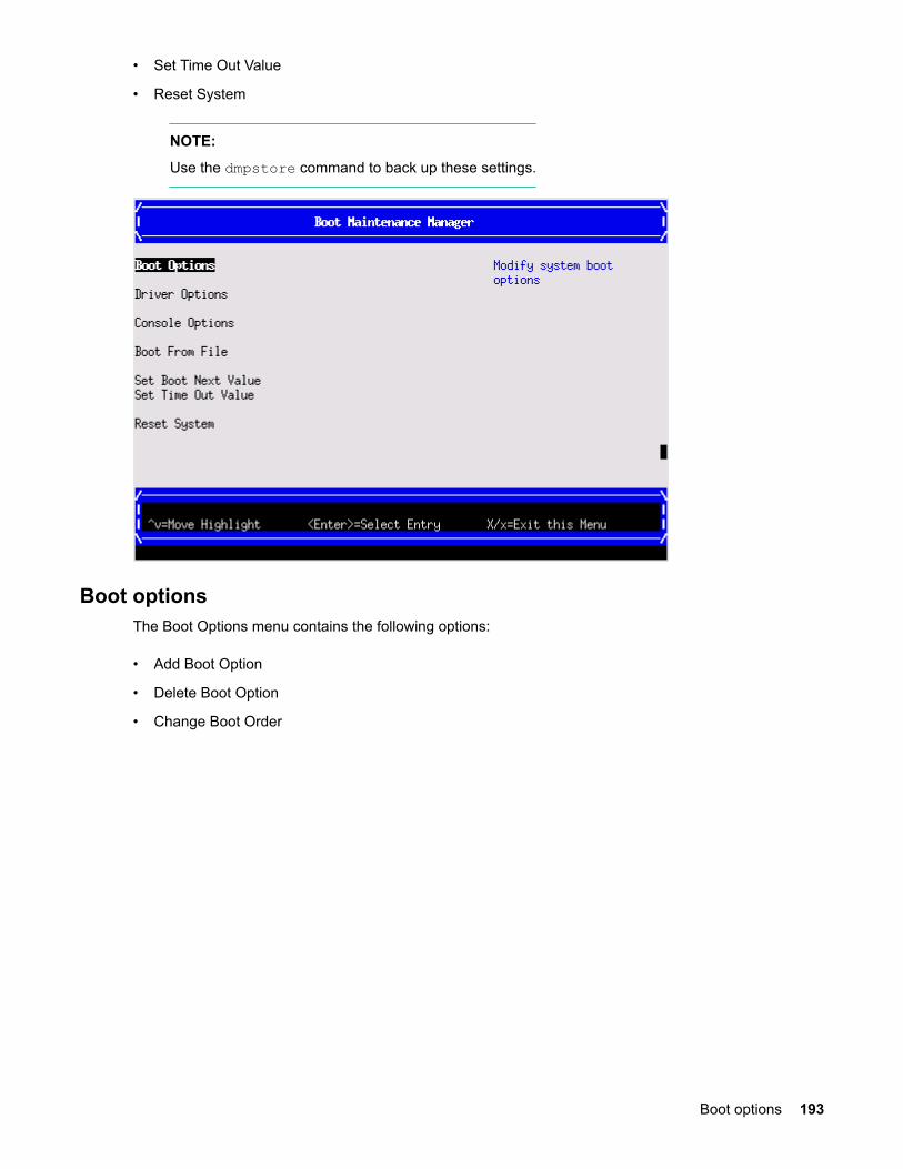
• Set Time Out Value
• Reset System
NOTE:
Use the dmpstore command to back up these settings.
Boot optionsThe Boot Options menu contains the following options:
• Add Boot Option
• Delete Boot Option
• Change Boot Order
Boot options 193
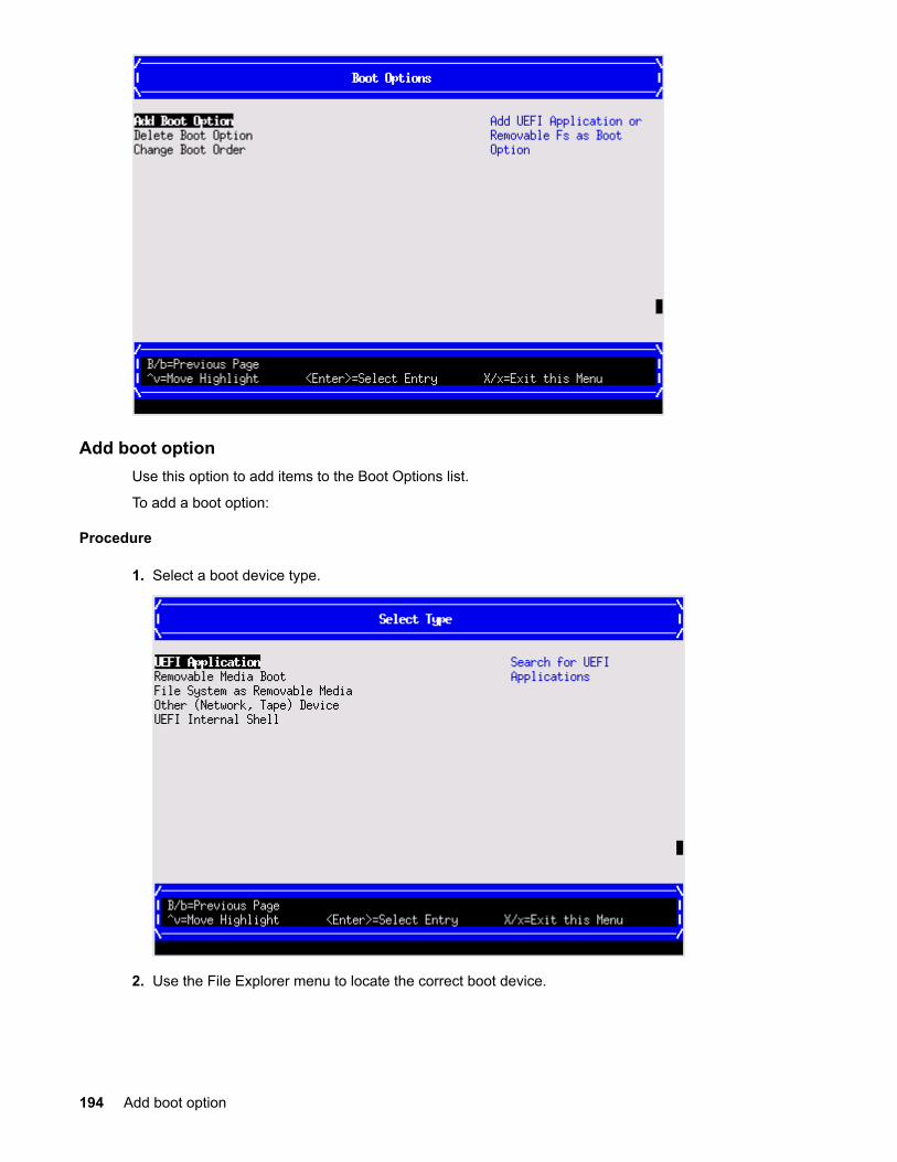
Add boot optionUse this option to add items to the Boot Options list.
To add a boot option:
Procedure
1. Select a boot device type.
2. Use the File Explorer menu to locate the correct boot device.
194 Add boot option

NOTE:
File Explorer loads with the appropriate devices for the selected boot device.
Delete boot optionUse this option to remove boot options from the Boot Options list.
NOTE:
This does not delete any files, applications or drivers from your server.
To remove items from the boot list:
Delete boot option 195
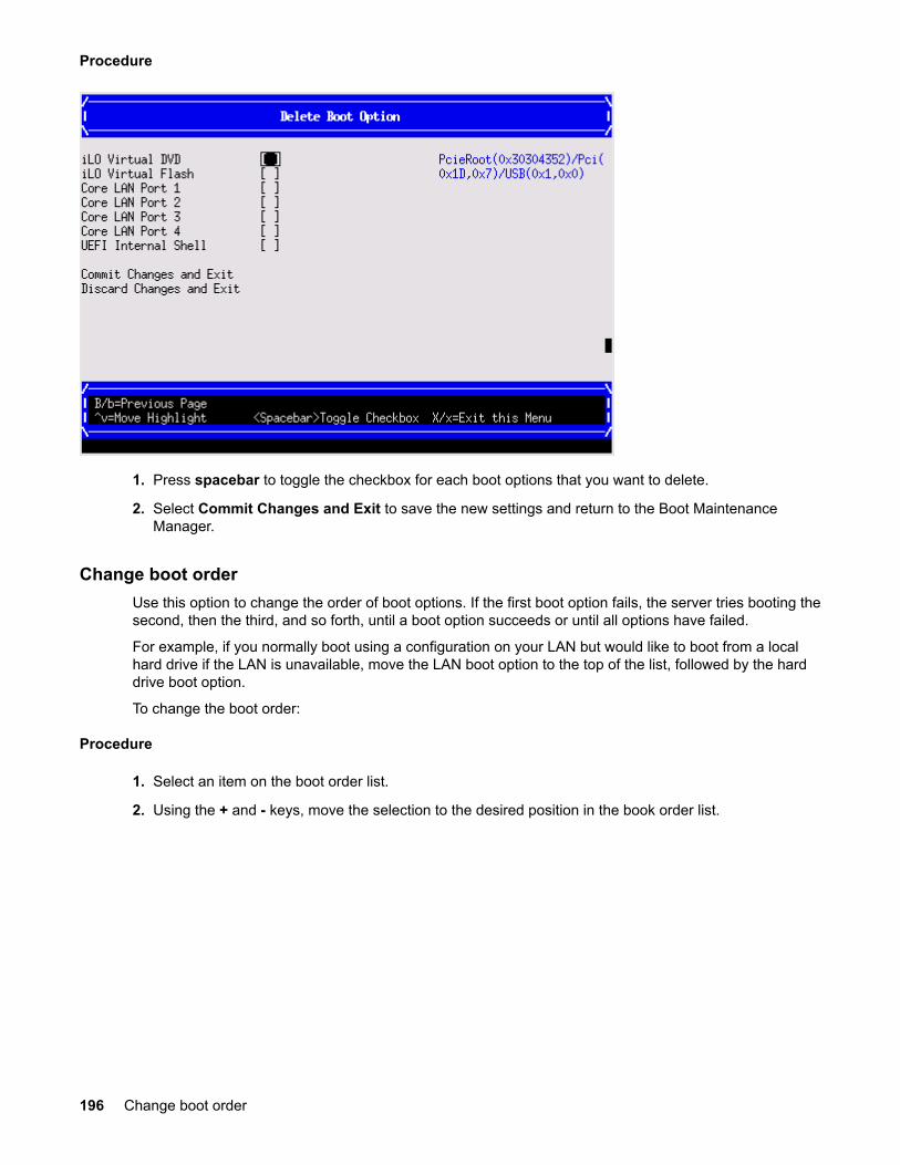
Procedure
1. Press spacebar to toggle the checkbox for each boot options that you want to delete.
2. Select Commit Changes and Exit to save the new settings and return to the Boot MaintenanceManager.
Change boot orderUse this option to change the order of boot options. If the first boot option fails, the server tries booting thesecond, then the third, and so forth, until a boot option succeeds or until all options have failed.
For example, if you normally boot using a configuration on your LAN but would like to boot from a localhard drive if the LAN is unavailable, move the LAN boot option to the top of the list, followed by the harddrive boot option.
To change the boot order:
Procedure
1. Select an item on the boot order list.
2. Using the + and - keys, move the selection to the desired position in the book order list.
196 Change boot order
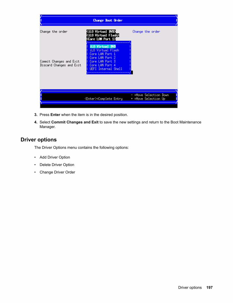
3. Press Enter when the item is in the desired position.
4. Select Commit Changes and Exit to save the new settings and return to the Boot MaintenanceManager.
Driver optionsThe Driver Options menu contains the following options:
• Add Driver Option
• Delete Driver Option
• Change Driver Order
Driver options 197

Add driver optionUse this option to add driver options.
Procedure
1. Select Add Driver Using File.
2. Use the File Explorer menu to locate the correct driver.
198 Add driver option

Delete driver optionUse this option to remove driver options.
NOTE:
This does not delete any files, applications or drivers from your server.
To remove driver options:
Procedure
1. Press spacebar to toggle the checkbox for each driver that you want to delete.
2. Select Commit Changes and Exit to save the new settings and return to the Boot MaintenanceManager.
Change driver orderUse this option to change the load order of driver options.
To change the driver load order:
Procedure
1. Select an item on the driver list.
2. Using the + and - keys, move the selection to the desired position in the book order list.
3. Press Enter when the item is in the desired position.
4. Select Commit Changes and Exit to save the new settings and return to the Boot MaintenanceManager.
Delete driver option 199

Console optionsThe Console Options menu is not currently supported. Use the conconfig command from the UEFIShell to set console options.
Boot from fileUse this option to manually run a specific application or driver.
NOTE:
This option boots the selected application or driver one time only. When you exit the application, youreturn to this menu.
Procedure
1. Select a boot device type.
2. Use the File Explorer menu to locate the correct driver or file.
Set boot next valueUse this option to run the selected boot option immediately upon entering the main Boot Manager menu.This option is useful for booting an option that only needs to be booted once, without changing any othersetting in the main Boot Manager menu. This is a one-time operation and does not change the permanentserver boot settings.
200 Console options
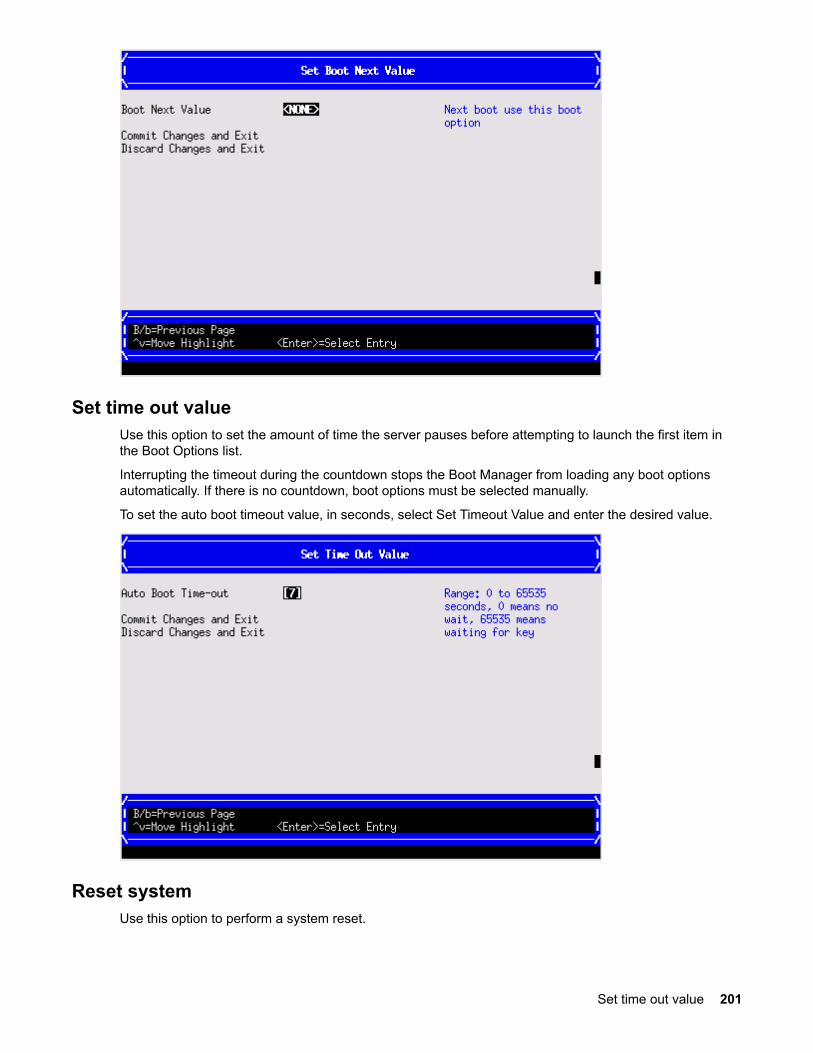
Set time out valueUse this option to set the amount of time the server pauses before attempting to launch the first item inthe Boot Options list.
Interrupting the timeout during the countdown stops the Boot Manager from loading any boot optionsautomatically. If there is no countdown, boot options must be selected manually.
To set the auto boot timeout value, in seconds, select Set Timeout Value and enter the desired value.
Reset systemUse this option to perform a system reset.
Set time out value 201
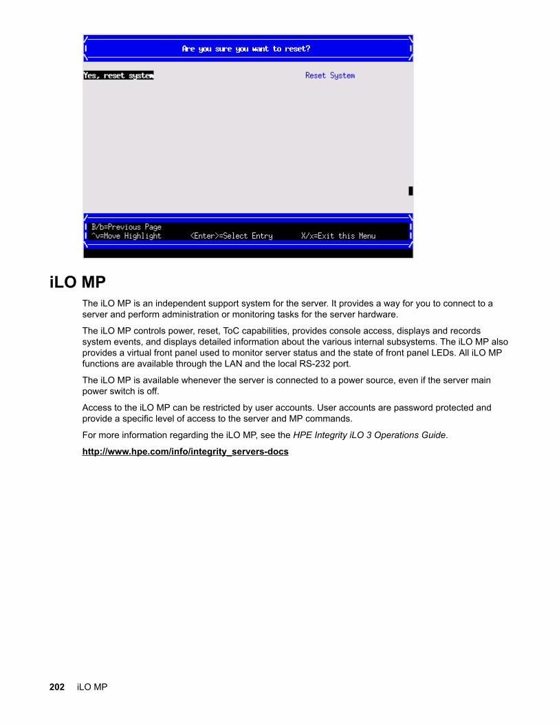
iLO MPThe iLO MP is an independent support system for the server. It provides a way for you to connect to aserver and perform administration or monitoring tasks for the server hardware.
The iLO MP controls power, reset, ToC capabilities, provides console access, displays and recordssystem events, and displays detailed information about the various internal subsystems. The iLO MP alsoprovides a virtual front panel used to monitor server status and the state of front panel LEDs. All iLO MPfunctions are available through the LAN and the local RS-232 port.
The iLO MP is available whenever the server is connected to a power source, even if the server mainpower switch is off.
Access to the iLO MP can be restricted by user accounts. User accounts are password protected andprovide a specific level of access to the server and MP commands.
For more information regarding the iLO MP, see the HPE Integrity iLO 3 Operations Guide.
http://www.hpe.com/info/integrity_servers-docs
202 iLO MP

Warranty and regulatory informationFor important safety, environmental, and regulatory information, see Safety and Compliance Informationfor Server, Storage, Power, Networking, and Rack Products, available at www.hpe.com/support/Safety-Compliance-EnterpriseProducts.
Warranty informationHPE ProLiant and x86 Servers and Options
www.hpe.com/support/ProLiantServers-Warranties
HPE Enterprise Servers
www.hpe.com/support/EnterpriseServers-Warranties
HPE Storage Products
www.hpe.com/support/Storage-Warranties
HPE Networking Products
www.hpe.com/support/Networking-Warranties
Regulatory information
Belarus Kazakhstan Russia marking
Manufacturer and Local Representative Information
Manufacturer information:
Hewlett Packard Enterprise Company, 3000 Hanover Street, Palo Alto, CA 94304 U.S.
Local representative information Russian:
• Russia
:
• Belarus
:
• Kazakhstan
:
Warranty and regulatory information 203
Local representative information Kazakh:
• Russia
:
• Belarus
:
• Kazakhstan
:
Manufacturing date:
The manufacturing date is defined by the serial number.
CCSYWWZZZZ (serial number format for this product)
Valid date formats include:
• YWW, where Y indicates the year counting from within each new decade, with 2000 as the startingpoint; for example, 238: 2 for 2002 and 38 for the week of September 9. In addition, 2010 is indicatedby 0, 2011 by 1, 2012 by 2, 2013 by 3, and so forth.
• YYWW, where YY indicates the year, using a base year of 2000; for example, 0238: 02 for 2002 and38 for the week of September 9.
Turkey RoHS material content declaration
Ukraine RoHS material content declaration
204 Turkey RoHS material content declaration