how to use a command table · this feature allows the user to define simple command sequences,...
TRANSCRIPT
Classification: [x] Public
[x] LinMot internally
May 2018 0185-0012_E_1V0_AN_HT_CommandTable
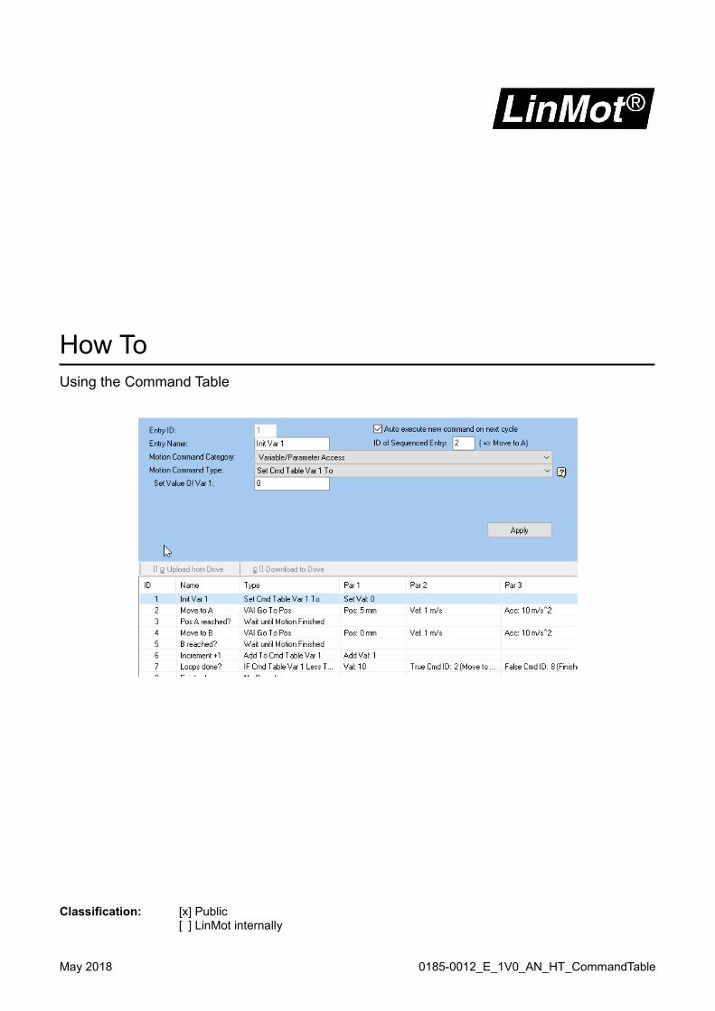
How To
Using the Command Table

Page 2 of 27 www.linmot.com NTI AG / LinMot
Command Table ..................................................................................................................................................... 3
General information about Command Table ......................................................................................................... 3 1 Execution sources of Command Table ............................................................................................................ 4
1.1 Debugging Command Table ........................................................................................................................... 4 1.2 Run mode: Triggered Command Table ........................................................................................................... 5
1.3 Run mode: Command Table ........................................................................................................................... 6 1.4 Starting by PLC command .............................................................................................................................. 7 1.5 Starting with EasySteps .................................................................................................................................. 8 1.6 Using Command Table I/O Interface (only E1100-GP series)......................................................................... 9
2 Editing Command Table .................................................................................................................................. 10 2.1 Enter a command .......................................................................................................................................... 11 2.2 Delete commands ......................................................................................................................................... 12 2.3 Move / add a new line ................................................................................................................................... 12
2.4 Download the Command Table ..................................................................................................................... 12 2.5 Upload the Command Table ......................................................................................................................... 12
3 Command sequences ...................................................................................................................................... 13
3.1 Conditions ..................................................................................................................................................... 14 3.1.1 Wait conditions ......................................................................................................................................... 14 3.1.2 If conditions .............................................................................................................................................. 15
3.2 Variable / Parameter access ......................................................................................................................... 16 3.3 Access to I/O ................................................................................................................................................. 17
3.3.1 Creating bit mask ..................................................................................................................................... 18 3.3.2 Check input value ..................................................................................................................................... 19
3.3.3 Set output ................................................................................................................................................. 20 4 Examples ........................................................................................................................................................... 22
4.1 Example 1: Controlled switch off ................................................................................................................... 22 4.2 Simple loop counter ...................................................................................................................................... 23 4.3 Storing a Command Table variable value permanently on the drive ............................................................ 24
4.4 Application: Foam rubber testing .................................................................................................................. 25
5 Version History ................................................................................................................................................. 27
NTI AG / LinMot www.linmot.com Page 3 of 27
Command Table
LinMot drives provide a feature which is called the Command Table. This feature allows the user to define simple command sequences, similar to a simple PLC program. The Command Table feature is no substitution for a PLC. Functions are limited compared to a PLC. Typical use examples are simple motion sequences for standalone applications like test rigs, where some movements must be repeated over long time. The Command Table acts as a simulated interface. The interface on LinMot drives is typically a fieldbus, which controls the drive. Instead of using a fieldbus, the command table can simulate interface commands.
Attention: The Command Table can be started over a fieldbus by a motion command! When the command table is running, ensure, no motion commands are sent over the fieldbus to prevent any unexpected behavior! A running command table is signaled in “Status Word Bit 8: Event Handler Active”. This bit can be observed by a PLC to check when the command table has finished!
Attention: LinMot firmware allows use of input lines in several sections of the firmware. If you use an input in the drive I/O definitions at the same time as EasySteps or the Command Table, unexpected behavior may occur! Use each input only for one task, or ask Support if multiple use may be possible or not!
General information about Command Table
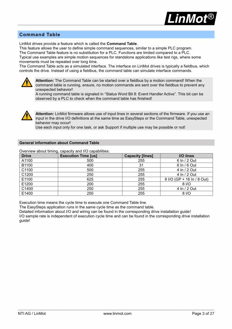
Overview about timing, capacity and I/O capabilities:
Drive Execution Time [us] Capacity [lines] I/O lines
A1100 500 255 6 In / 2 Out
B1100 400 31 6 In / 6 Out
C1100 500 255 4 In / 2 Out
C1200 250 255 4 In / 2 Out
E1100 625 255 8 I/O (GP + 16 In / 8 Out)
E1200 200 255 8 I/O
C1400 250 255 4 In / 2 Out
E1400 250 255 8 I/O
Execution time means the cycle time to execute one Command Table line. The EasySteps application runs in the same cycle time as the command table. Detailed information about I/O and wiring can be found in the corresponding drive installation guide! I/O sample rate is independent of execution cycle time and can be found in the corresponding drive installation guide!

Page 4 of 27 www.linmot.com NTI AG / LinMot
1 Execution sources of Command Table
Command Table execution can be started several ways. For starting the command table, a unique command table ID is used to address the command line, which should be started as an entry point. Depending on the selected run mode or command table execution, command table sequences must be handled as infinite loops or with an end point. The Command table will stop when no new Link ID is entered. If the next link ID points to any valid ID the command table will continue. If a Link ID goes back to a previously executed command then the Command Table is proceeding in a loop. A running command table cannot be stopped directly! If the motor is switched off by Control Word bit 0, remember that the Command Table is still running. If a motion command is used in this phase, the drive goes into an error- “User Err: Motion Cmd In Wrong St”. Switching off the motor by Control Word bit 0 or any other sources (STO, Quickstop) should be handled in the Command Table to prevent sending new motion commands. The Command Table should be stopped by calling motion command “Clear Event Evaluation”. The following chapters will show the different options of Command Table features and samples to develop your own applications.
1.1 Debugging Command Table
For testing purposes, Command Table execution can be observed in the variables section:
When the Command Table is running, you can observe both variables 1 & 2 and the actual linked line and the last linked line. This may be helpful to figure out which line sequence is working. This is especially helpful when “IF” conditions are used. These variables may be recorded by the Oscilloscope as well. This is helpful if the detailed debugging of conditions are too fast in the variable view.

NTI AG / LinMot www.linmot.com Page 5 of 27
1.2 Run mode: Triggered Command Table
The Command table can be executed by a hardware trigger signal. For this use, the run mode of the drive must be set as follows in the parameter tree:
Function Value UPID (B1100) UPID (all other) Description
Set run mode \Parameters\Motion Control SW\Motion Interface\Run Mode Settings\Run Mode Selection
Triggered Command Table On 62A8h 1450h Run mode Triggered Command Table
Function Value UPID (B1100) UPID (all other) Description
Set ID rising trigger \Parameters\ Motion Control SW\Motion Interface\Run Mode Settings\Triggered Command Table Settings
Rise Command Table Entry ID
ID number 6302h 1486h ID number for execution
Function Value UPID (B1100) UPID (all other) Description
Set ID falling trigger \Parameters\ Motion Control SW\Motion Interface\Run Mode Settings\Triggered Command Table Settings
Fall Command Table Entry ID ID number 6303h 1487h ID number for execution
In the trigger settings, at least one of the two available parameters, must be set to a valid command table ID. Depending on the application, both rise and fall conditions can be used.
Note: B1100 differs from UPID addresses to other drive series! Trigger input is fixed to a specific input, which is sampled faster compared to other inputs. Trigger input cannot be changed to different input lines!
For using this run mode, the trigger input must be configured as follows:
Function Value UPID (B1100) UPID (all other) Description
Define Trigger Input \Parameters\Motion Control SW\Drive Configuration\X4/X14 IO Definitions\
IO X4.6 (not B1100) 01 - Trigger - 1039h Set hardware trigger
IO X14.15 (B1100) 01 - Trigger 62EAh - Set hardware trigger
Function Value UPID (B1100) UPID (all other) Description
Define trigger mode \Parameters\Motion Control SW\Drive Configuration\X4/X14 IO Definitions\Trigger\
Trigger Mode 01 - Direct 62D8h 170Ch Trigger evaluation mode
Depending on selected Trigger Mode, inhibit and delay times can be defined in “Trigger Settings”
Attention: Using triggered command table requires short, non-blocking command table sequences!
Attention: Command Table sequences must end! Do not build infinite loops!
Attention: Ensure sequences are finished before a new trigger occurs to prevent any unsuspected behavior!

Page 6 of 27 www.linmot.com NTI AG / LinMot
1.3 Run mode: Command Table
The Command Table can be directly executed. Command Table execution starts immediately after first switch on when the drive is homed. For use of this feature, the run mode of the drive must be set as follows in the parameter tree:
Function Value UPID (B1100) UPID (all other) Description
Set run mode \Parameters\Motion Control SW\Motion Interface\Run Mode Settings\Run Mode Selection
Command Table Mode On 62A8h 1450h Run mode Command Table Mode
Function Value UPID (B1100) UPID (all other) Description
Set Entry ID \Parameters\ Motion Control SW\Motion Interface\Run Mode Settings\Command Table Settings
Command Table Entry ID ID number 6301h 1485h ID number for execution
In this mode if the Command Table ends with no link ID then the Command Table execution stops when the last line is reached and will restart when the drive is switched off then back on with Control Word bit 0. If in this mode and the Command Table is internally linked back to the entry point, the Command Table execution will never stop until the drive is switched off with Control Word bit 0. Switching Control Word bit 0 back on will proceed with the Command Table execution. Command Table execution will continue from the last evaluated command table ID. Depending on the application, this behavior must be considered to prevent any unexpected behavior!

NTI AG / LinMot www.linmot.com Page 7 of 27
1.4 Starting by PLC command
The Command Table may be started by the PLC over a fieldbus, which works in parallel to the Command Table. The User must ensure that only one sequence source is active! If the Command Table is started then the PLC must never send any motion commands until the command table has finished! For starting the Command Table, the PLC sends motion command “Start Command Table Command (200xh)” with parameter word 1 containing the entry ID of the Command Table. If LinMot PLC libraries are used, there is a predefined function block for starting the command table included. To observe a running Command table, the PLC must check bit 8 “Event Handler Active” in the Status Word. As long as this bit is set the Command Table is running. To skip the Command Table execution, it is possible to send motion command “Clear Event Evaluation (008xh)”, which is available in most function block libraries as well.
Page 8 of 27 www.linmot.com NTI AG / LinMot
1.5 Starting with EasySteps
If the optional application software “EasySteps” is installed on the drive, the Command Table may be executed by EasySteps. Details about this application can be found in the corresponding manual http://shop.linmot.com/E/product/0185-1037-E With EasySteps some inputs can be configured to evaluate a Command Table line (depends on the drive). This can be used instead of “Triggered Command Table”. It must be ensured, that the Command Table sections are finished, before the next input is triggered!
Attention: Using EasySteps to evaluate Command Table lines, short, non-blocking command table sequences are required! Ensure sequences are finished, before a new trigger occurs to prevent any undesirable behavior!
Attention: Command Table sequences must end! Do not build infinite loops!
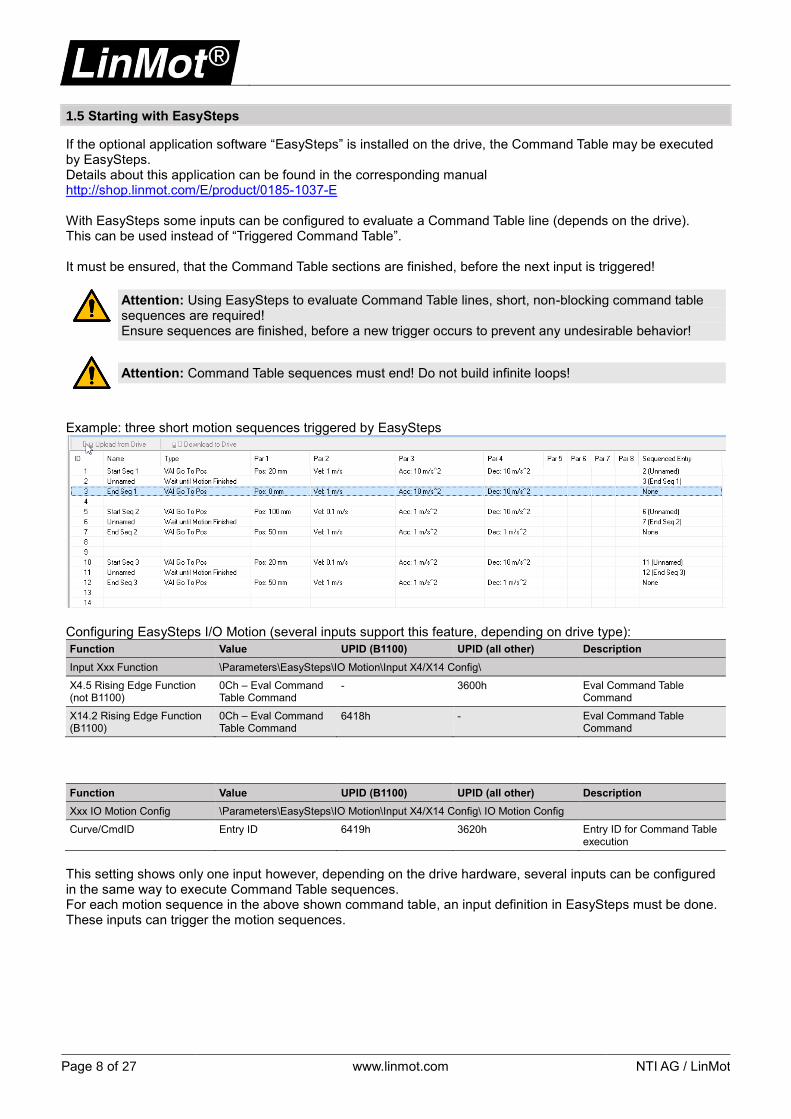
Example: three short motion sequences triggered by EasySteps
Configuring EasySteps I/O Motion (several inputs support this feature, depending on drive type):
Function Value UPID (B1100) UPID (all other) Description
Input Xxx Function \Parameters\EasySteps\IO Motion\Input X4/X14 Config\
X4.5 Rising Edge Function (not B1100)
0Ch – Eval Command Table Command
- 3600h Eval Command Table Command
X14.2 Rising Edge Function (B1100)
0Ch – Eval Command Table Command
6418h - Eval Command Table Command
Function Value UPID (B1100) UPID (all other) Description
Xxx IO Motion Config \Parameters\EasySteps\IO Motion\Input X4/X14 Config\ IO Motion Config
Curve/CmdID Entry ID 6419h 3620h Entry ID for Command Table execution
This setting shows only one input however, depending on the drive hardware, several inputs can be configured in the same way to execute Command Table sequences. For each motion sequence in the above shown command table, an input definition in EasySteps must be done. These inputs can trigger the motion sequences.
NTI AG / LinMot www.linmot.com Page 9 of 27
1.6 Using Command Table I/O Interface (only E1100-GP series)
Command Table I/O Interface is a special feature on E1100-GP drives, which allows selection of each command table line by a binary coded bit structure over the X6 I/O connector. Details can be found in the user manual http://shop.linmot.com/E/product/0185-1077-E
Page 10 of 27 www.linmot.com NTI AG / LinMot
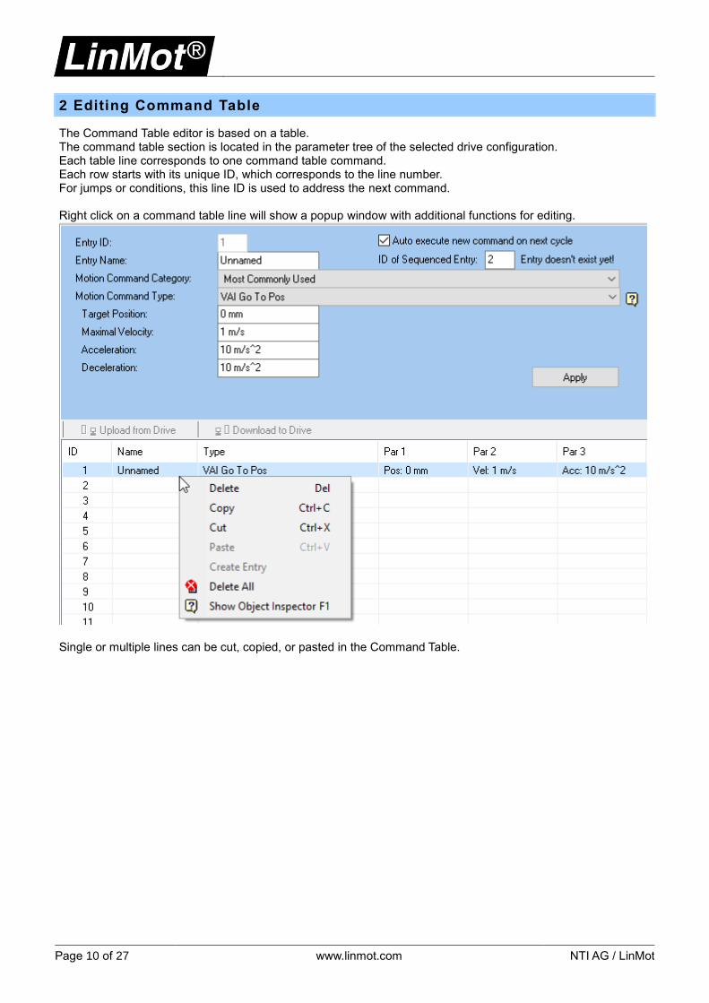
2 Editing Command Table
The Command Table editor is based on a table. The command table section is located in the parameter tree of the selected drive configuration. Each table line corresponds to one command table command. Each row starts with its unique ID, which corresponds to the line number. For jumps or conditions, this line ID is used to address the next command. Right click on a command table line will show a popup window with additional functions for editing.
Single or multiple lines can be cut, copied, or pasted in the Command Table.
NTI AG / LinMot www.linmot.com Page 11 of 27
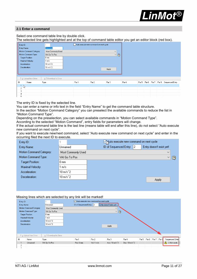
2.1 Enter a command
Select one command table line by double click. The selected line gets highlighted and at the top of command table editor you get an editor block (red box).
The entry ID is fixed by the selected line. You can enter a name or info text in the field “Entry Name” to get the command table structure. In the section “Motion Command Category” you can preselect the available commands to reduce the list in “Motion Command Type”. Depending on the preselection, you can select available commands in “Motion Command Type”. According to the selected “Motion Command”, entry fields for parameters will change. If the actual command table line is the last line (means table will end after this line), do not select “Auto execute new command on next cycle”. If you want to execute new/next command, select “Auto execute new command on next cycle” and enter in the occurring filed the next ID to execute.
Missing lines which are selected by any link will be marked!
Page 12 of 27 www.linmot.com NTI AG / LinMot
2.2 Delete commands
Select the line or lines to be deleted and perform right mouse click to show popup window. Select Delete (or press del key).
Attention: Clicking on “Delete All” will clear the complete command table!
2.3 Move / add a new line
Moving command table lines may be necessary to get space for new additional lines. It’s not possible to insert a new line directly. To get space for additional lines, you need to select lines, cut them out and paste them in at the new location. Multiple lines in one block can be cut and pasted. For pasting the lines all needed target lines must be empty or they will be overwritten! Linked ID’s especially ID’s in conditions will not automatically renumbered! This must be done manually!
Attention: Pasted lines (after copy or cut) will not be automatically renumbered in the linked ID or in conditions! This must be done manually!
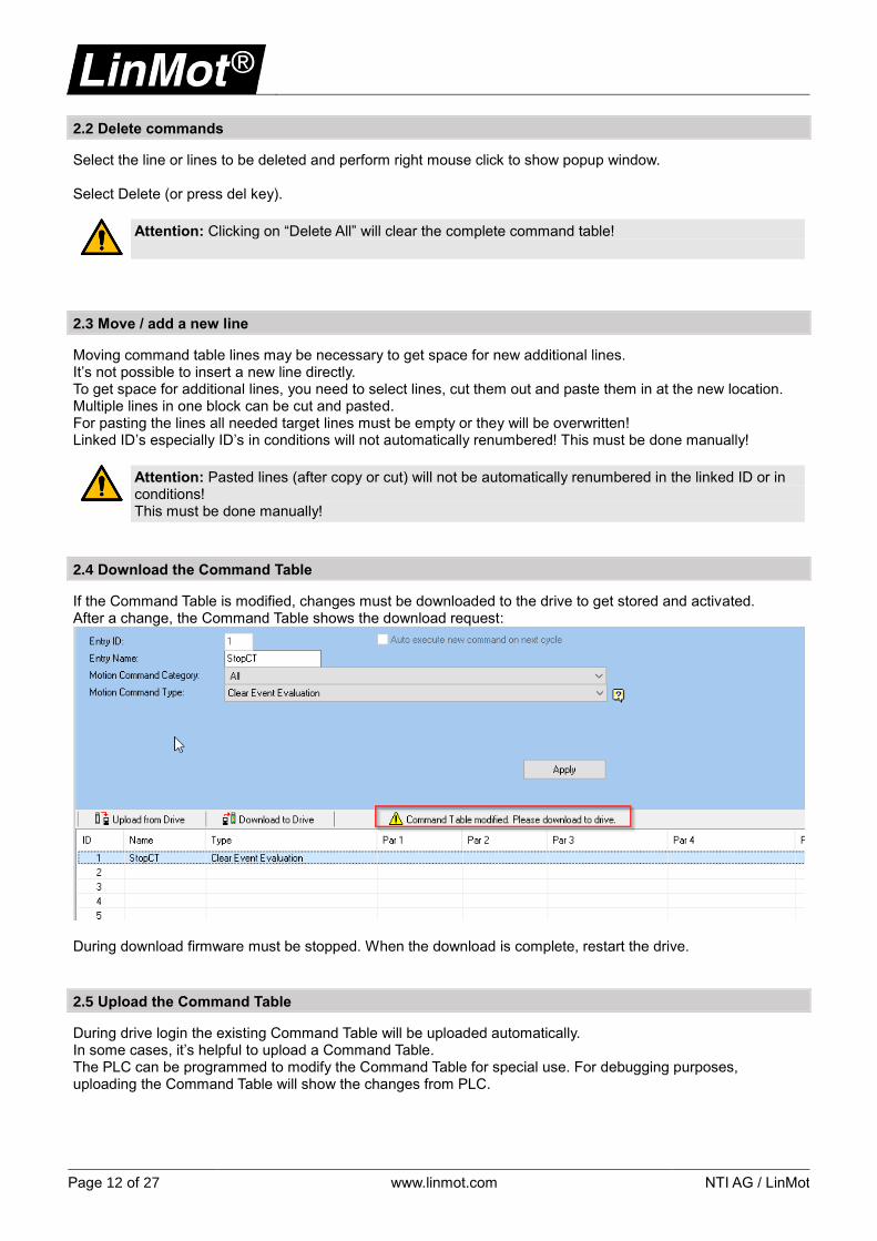
2.4 Download the Command Table
If the Command Table is modified, changes must be downloaded to the drive to get stored and activated. After a change, the Command Table shows the download request:
During download firmware must be stopped. When the download is complete, restart the drive.
2.5 Upload the Command Table
During drive login the existing Command Table will be uploaded automatically. In some cases, it’s helpful to upload a Command Table. The PLC can be programmed to modify the Command Table for special use. For debugging purposes, uploading the Command Table will show the changes from PLC.

NTI AG / LinMot www.linmot.com Page 13 of 27
3 Command sequences
Depending on the particular drive, you have several available commands. You can use each motion command, which is supported on the particular drive. A list of the commands can be found in the user manual motion control: For B1100/E1100 series http://shop.linmot.com/E/product/0185-1092-E For all other series http://shop.linmot.com/E/product/0185-1093-E The drives provide additional commands, which are only foreseen for use in the Command Table like: conditions, parameter access, and I/O access for example.

Page 14 of 27 www.linmot.com NTI AG / LinMot
3.1 Conditions
The Command Table provide several conditions to control command table execution. There are two main groups of conditions:
- Waiting conditions (wait until the condition becomes true, before executing the linked ID) - If conditions (link to ID depending on if condition, no wait)
3.1.1 Wait conditions
For simple motion sequences, its sufficient to use “Wait” conditions. These conditions will execute next ID, when a condition is true. For example: Move to position A, when motion finished, move to position B:
Execution starts in line 1 by moving the motor to a position of 10mm, link to line 2. While the motor moves to position A, condition in line 2 waits until VA interpolator is finished (motion curve is done). Then line 3 will executed and command table ends directly, while motor still moves until position is reached.
Note: For simple movements as a sequence, use wait conditions! Without conditions, running command will be overwritten with next linked command! If the wait condition is removed in the above sequence the motor starts with position A and the command will be overwritten with position B, so only movement to position B will be observed!
Note: Difference: Wait until motion finished – Wait until in target position First command waits until VA interpolator is finished, while second command waits until position is in the check window of “Status In Target Position”.
List of wait-conditions:
• Wait Time (210xh)
• Wait Until Motion Finished (211xh)
• Wait Until In Target Position (212xh)
• Wait Until Rising Trigger Event (213xh)
• Wait Until Falling Trigger Event (214xh)
• Wait Until Demand Position Greater Than (220xh)
• Wait Until Demand Position Less Than (221xh)
• Wait Until Actual Position Greater Than (222xh)
• Wait Until Actual Position Less Than (223xh)
• Wait Until Difference Position Greater Than (224xh)
• Wait Until Difference Position Less Than (225xh)
• Wait Until Difference Position Unsigned Greater Than (226xh)
• Wait Until Difference Position Unsigned Less Than (227xh)
• Wait Until Demand Velocity Greater Than (228xh)
• Wait Until Demand Velocity Less Than (229xh)
• Wait Until Actual Velocity Greater Than (22Axh)
• Wait Until Actual Velocity Less Than (22Bxh)
• Wait Until Current Greater Than (22Exh)
• Wait Until Current Less Than (22Fxh)
Attention: Check the corresponding motion control software manual to verify if the listed command is supported on your particular drive!

NTI AG / LinMot www.linmot.com Page 15 of 27
3.1.2 If conditions
Note: While using IF conditions, never set one of the both link ID’s to its own entry ID! This will cause a Trap Class A error! All command table lines will be executed in one interface software cycle of the firmware. This ensures constant execution timing, but this does not allow direct loop back! It is recommended never call an IF condition from an IF condition!
For some applications handled by command table, its useful to have an if condition. For example, during movement to a position, the IF condition should check that specific motor current is reached to detect a target by current increase.
Line 1 will start a movement to 100mm and jump into line 2. Line 2 check, if motor current is greater than 5A, like when hitting an obstruction, then jump to line 10, or less than 5A to jump to line 3. Line 3 will loop back IF condition into line 2, because no direct loop backs from IF condition itself are allowed! Line 3 is needed to decouple the IF condition loop back. Line 10 will execute, here it’s just moving back to 0 and ending command table execution. List of IF conditions:
• IF Cmd Table Var 1 Less Than (250xh)
• IF Cmd Table Var 1 Greater Than (251xh)
• IF Cmd Table Var 2 Less Than (252xh)
• IF Cmd Table Var 2 Greater Than (253xh)
• IF Cmd Table Var 1 Less Than UPID Value (256xh)
• IF Cmd Table Var 2 Less Than UPID Value (257xh)
• IF Demand Position Less Than (258xh)
• IF Demand Position Greater Than (259xh)
• IF Actual Position Less Than (25Axh)
• IF Actual Position Greater Than (25Bxh)
• IF Difference Position Less Than (25Cxh)
• IF Difference Position Greater Than (25Dxh)
• IF Current Less Than (25Exh)
• IF Current Greater Than (25Fxh)
• IF Analog Val On X4.4 Less Than (260xh)
• IF Masked X4 Input Value Equal Than (262xh) (E1100, E1200, C1100, C1200, C1400, E1400)
• IF Masked X14 Input Value Equal Than (262xh) (B1100)
• IF Masked X6 Input Value Equal Than (263xh) (only E1100-GP)
• IF Masked Status Word Equal Than (264xh)
• IF Masked Warn Word Equal Than (265xh)
• IF CAM Counts Less Than (266xh)
Attention: Check the corresponding motion control software manual to verify if the listed command is supported on your particular drive!

Page 16 of 27 www.linmot.com NTI AG / LinMot
3.2 Variable / Parameter access
Command Table feature provide two variables to store temporary data. Data type is adopted automatically from the data source data type. These variables can both be set to a specific value and can be incremented and used in IF conditions as well. If a loop counter is needed, this can be done with a variable. Variables can be loaded with a value from the drive RAM by its UPID address as well as writing variable content to a UPID address. Variables can be observed with LinMot Talk variable section – Command Table or read by PLC. For example, a loop counter is needed to repeat a specific amount of motion cycles:
In this example, command table execution starts in line 1, where counter is preset to “0”. Then, motion is performed in lines 2 to 5. In line 6, variable 1 gets incremented with +1. Line 7 checks, if variable 1 is less than 10 loops to repeat at line 2 or jump to line 8 and finish command table. This sample will repeat the both movements 10 times. List of Variable / Parameter access
• Set Cmd Table Var 1 To (240xh)
• Add To Cmd Table Var 1 (241xh)
• Set Cmd Table Var 2 To (242xh)
• Add To Cmd Table Var 2 (243xh)
• Write Cmd Table Var 1 To UPID RAM value (248xh)
• Write Cmd Table Var 2 To UPID RAM value (249xh)
• Write UPID RAM Value To Cmd Table Var 1 (24Cxh)
• Write UPID RAM Value To Cmd Table Var 2 (24Dxh)
• Write UPID RAM value To UPID ROM value (24Exh)
Note: If you need to do something like a count down, increment variable with “-“ sign. E.g. increment value “-1” instead of “1” will count down the used variable.
Attention: Check the corresponding motion control software manual to verify if the listed command is supported on your particular drive!

NTI AG / LinMot www.linmot.com Page 17 of 27
3.3 Access to I/O
With a command table sequence, you can access the drive I/O. For reading an input, no additional settings according I/O must be done. If you want to set an output, this I/O line must be configured as “Interface Output” as follows: Configuring of an output for use with Command Table:
Function Value UPID (B1100) UPID (all other) Description
Define Output \Parameters\Motion Control SW\Drive Configuration\X4/X14 IO Definitions\
IO X4.3 (not B1100) 0Eh – Interface Output - 1036h Set X4.3 as output
IO X14.17 (B1100) 0Eh – Interface Output 62EEh - Set X14.17 as output
For checking an input state with an IF condition or to set one or several outputs a bit mask is required to define the input/output line. The bit mask selects the needed bits from the input or output register. The B1100 and C series drives define input and output lines separately, while all E1XX0 drives provide I/O lines. This means that the lines can be configured as input or output. Without any configuration, each I/O line is always an input. The following inputs and outputs on the B1100 series drives are available:
Bit counting direction from top to bottom. The following inputs and outputs on the C1X00 series drives are available:
Bit counting direction from top to bottom.

Page 18 of 27 www.linmot.com NTI AG / LinMot
All E1XX0 drive series provide I/O lines, configurable as input/output lines:
Bit counting from bottom to top. Depending on drive, I/O count varies up to X4.12 (bit 9). 3.3.1 Creating bit mask
Creating a bit mask means, you set a bit, which should be used in the mask byte.
This can simply be done by mathematical equation: 𝑚𝑎𝑠𝑘 𝑣𝑎𝑙𝑢𝑒 = 2𝐵𝑖𝑡𝑛𝑢𝑚𝑏𝑒𝑟 Example on B1100 inputs:
Bit mask for X14.3, bit number 3 -> 23 = 8 = 8ℎ = 0000 1000 Example for B1100 outputs:
Bit mask for X14.17, bit number 0 -> 20 = 1 = 1ℎ = 0000 0001 Bit mask for X14.6, bit number 3 ->23 = 8 = 8ℎ = 0000 1000 A bit mask allows to select several bits at same time. To do so, you need to add each calculated bit value. Example on E1100: Bit mask for X4.4, bit number 1 -> 21 = 2 = 2ℎ = 0000 0010
Bit mask for X4.9, bit number 6 -> 26 = 64 = 40ℎ = 0100 0000
Sum: 𝐵𝑖𝑡 𝑚𝑎𝑠𝑘 = 21 + 26 = 2 + 64 = 66 = 42ℎ = 0100 0010 This bit mask will observe X4.4 and X4.9. A bit mask is a logical AND equation. All bit numbers for I/O lines starts with count 0 for X4.3 and increase up to last I/O, except B1100. B1100 starts bit counting in the I/O panel from top to down (see screenshot). Inputs and outputs are separate blocks, while other drive I/O lines are in same block.

NTI AG / LinMot www.linmot.com Page 19 of 27
3.3.2 Check input value
Checking input values can be done by using IF command “IF Masked X4 Input Value Equal Than (262xh)”. Here, a bit mask and compare value is required to check if the input line is set. Example: checking, if X4.5 is set on E1100 drive:
X4.5 bit value = 2 -> 22 = 4 = 04ℎ = 0000 0100
Line 1 is checking if the masked input corresponds with its bit value (same as bit mask) for proceeding in line 10, otherwise it loops via line 2 back into line 1. Example: checking, if X4.5 is set and X4.7 is not set on E1100 drive:
Bit mask: = 𝐵𝑖𝑡𝑚𝑎𝑠𝑘 = 22 + 24 = 20 = 14ℎ = 0001 0100
Compare value: 𝐶𝑜𝑚𝑝𝑎𝑟𝑒𝑉𝑎𝑙𝑢𝑒 = 1 ∗ 22 + 0 ∗ 24 = 4 = 04ℎ = 0000 0100
This IF condition will link to line 10, if X4.5 is set and X4.7 is not set.
Page 20 of 27 www.linmot.com NTI AG / LinMot
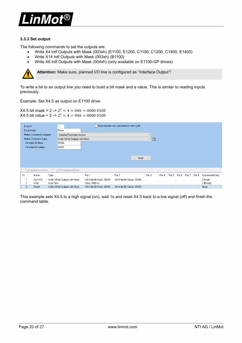
3.3.3 Set output
The following commands to set the outputs are:
• Write X4 Intf Outputs with Mask (003xh) (E1100, E1200, C1100, C1200, C1400, E1400)
• Write X14 Intf Outputs with Mask (003xh) (B1100)
• Write X6 Intf Outputs with Mask (004xh) (only available on E1100-GP drives)
Attention: Make sure, planned I/O line is configured as “Interface Output”!
To write a bit to an output line you need to build a bit mask and a value. This is similar to reading inputs previously. Example: Set X4.5 as output on E1100 drive:
X4.5 bit mask = 2 -> 22 = 4 = 04ℎ = 0000 0100
X4.5 bit value = 2 -> 22 = 4 = 04ℎ = 0000 0100
This example sets X4.5 to a high signal (on), wait 1s and reset X4.5 back to a low signal (off) and finish the command table.
NTI AG / LinMot www.linmot.com Page 21 of 27
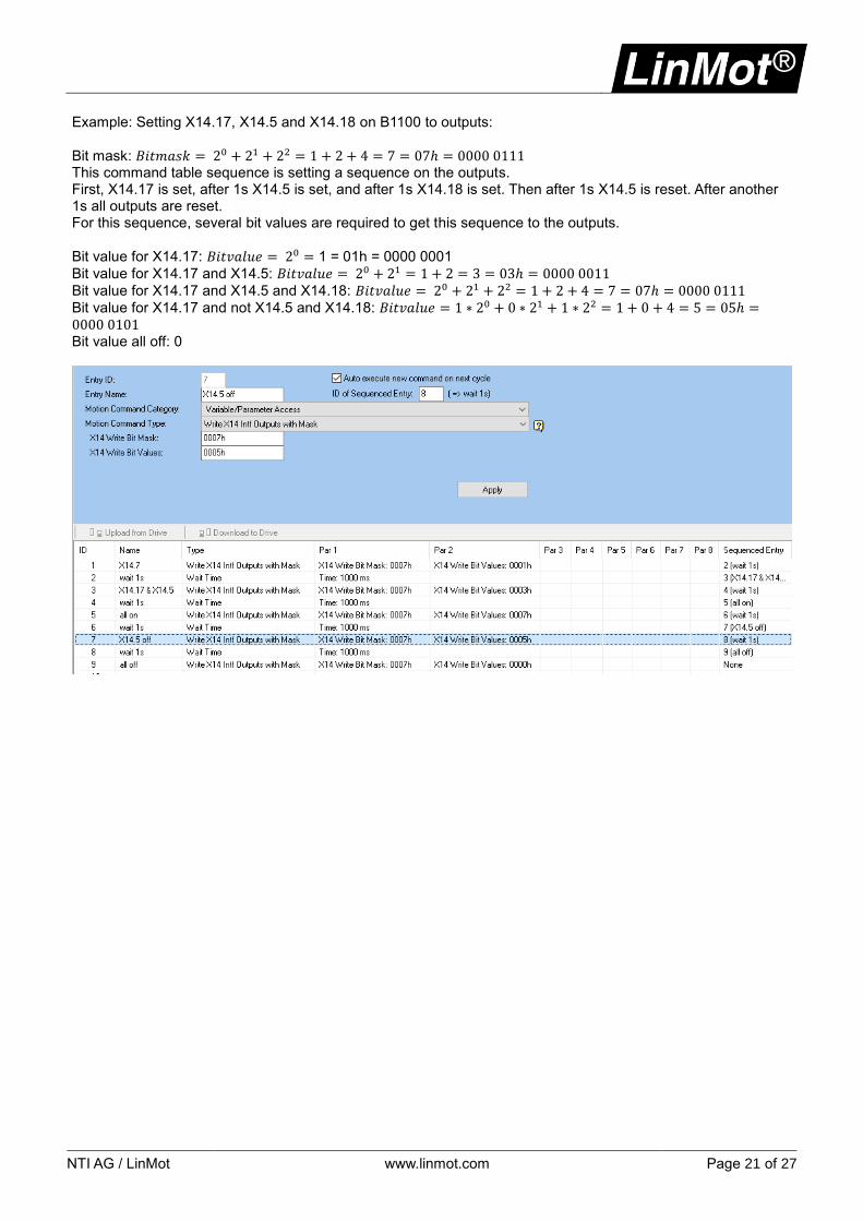
Example: Setting X14.17, X14.5 and X14.18 on B1100 to outputs:
Bit mask: 𝐵𝑖𝑡𝑚𝑎𝑠𝑘 = 20 + 21 + 22 = 1 + 2 + 4 = 7 = 07ℎ = 0000 0111 This command table sequence is setting a sequence on the outputs. First, X14.17 is set, after 1s X14.5 is set, and after 1s X14.18 is set. Then after 1s X14.5 is reset. After another 1s all outputs are reset. For this sequence, several bit values are required to get this sequence to the outputs.
Bit value for X14.17: 𝐵𝑖𝑡𝑣𝑎𝑙𝑢𝑒 = 20 = 1 = 01h = 0000 0001
Bit value for X14.17 and X14.5: 𝐵𝑖𝑡𝑣𝑎𝑙𝑢𝑒 = 20 + 21 = 1 + 2 = 3 = 03ℎ = 0000 0011
Bit value for X14.17 and X14.5 and X14.18: 𝐵𝑖𝑡𝑣𝑎𝑙𝑢𝑒 = 20 + 21 + 22 = 1 + 2 + 4 = 7 = 07ℎ = 0000 0111
Bit value for X14.17 and not X14.5 and X14.18: 𝐵𝑖𝑡𝑣𝑎𝑙𝑢𝑒 = 1 ∗ 20 + 0 ∗ 21 + 1 ∗ 22 = 1 + 0 + 4 = 5 = 05ℎ =0000 0101 Bit value all off: 0

Page 22 of 27 www.linmot.com NTI AG / LinMot
4 Examples
This chapter shows some simple sample command tables to see, how to solve simple tasks. All samples are done on E1100-GP drives with installed EasySteps application software! For each example it’s assumed drive is defaulted and motor is configured by motor wizard.
4.1 Example 1: Controlled switch off
This example uses EasySteps X4.4 to evaluate Command Table line 10 to start the sequence. (Using EasySteps is described in the manual http://shop.linmot.com/E/product/0185-1037-E Motor switching on and off is done by Control Word bit 0 (handled by control panel, and can be mapped to I/O). In this example, the motor will be moved to start position when X4.4 is triggered and the drive is operational. Line 10 checks if Status Word bit 0 is set, which means the drive is operational. During the movement to initial position there is no check for power off! After initialization, line 20 is executed. Then, there is a check if the drive is still operational. If not, line 1 will be executed to stop the command table. Otherwise, in line 23 Status Word bit 13, “Motion Active” is checked. If motion is still active, condition loop back to line 21, otherwise it starts line 25 for the next movement. For the next position, the same checks are done and then loop back to line 20. As long as Control Word bit 0 “Switch On” is active the motor will move between two positions. If Control Word bit 0 is off, the Command Table will stop. After Control Word bit 0 is set again, Command Table execution can be triggered again by X4.4. This sequence prevents sending motion commands when drive is not ready to move
NTI AG / LinMot www.linmot.com Page 23 of 27
4.2 Simple loop counter
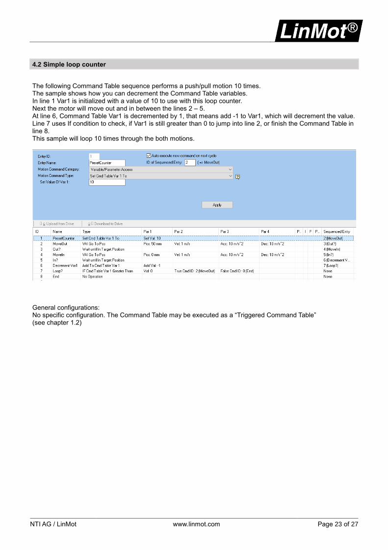
The following Command Table sequence performs a push/pull motion 10 times. The sample shows how you can decrement the Command Table variables. In line 1 Var1 is initialized with a value of 10 to use with this loop counter. Next the motor will move out and in between the lines 2 – 5. At line 6, Command Table Var1 is decremented by 1, that means add -1 to Var1, which will decrement the value. Line 7 uses If condition to check, if Var1 is still greater than 0 to jump into line 2, or finish the Command Table in line 8. This sample will loop 10 times through the both motions.
General configurations: No specific configuration. The Command Table may be executed as a “Triggered Command Table” (see chapter 1.2)

Page 24 of 27 www.linmot.com NTI AG / LinMot
4.3 Storing a Command Table variable value permanently on the drive
This example shows how to store a value permanently on the drive. The sample use two digital inputs in Command Table mode. Input X4.3 is used to start a two-point motion, and X4.4 is used to teach the motion. In teaching mode, position change is done by using jog+ / jog- function of the drive. Teaching mode is only available when motion is running.
Line 1 will load the last stored position value into Var1 of the Command Table and proceed to line 2 and then line 3. Here, IF condition checks X4.3 to determine if motion should run or not. If X4.3 is a true condition we then proceed to line 4 and then line 5, where the teach mode is checked. If no teach is requested in line 5 we then move to line 6. The target position for this motion command is derived from Command Table Var1. When this position is reached, the motor moves back to 0mm then starts over again on line 2. If teach mode is requested in line 5 then we will loop to line 20. At line 20, an additional IF condition will loop in line 20 until the teaching mode with X4.4 is deactivated. Before this line get deactivated, the user must adjust position by the jog+/- bits. When X4.4 gets deactivated, the actual position value is stored in Command Table Var1 at line 22. This variable will be stored into RAM memory of the normally not used position controller set B variable “Spring Zero Position”. This Variable will be used as “storage”. Line 24 will finally save the RAM value of this variable into ROM memory. On each power up, the stored value gets copied into RAM and will be read out in line 1 at first start. General configurations:
Function Value UPID Description
Define Input “Move” \Parameters\Motion Control SW\Drive Configuration\X4/ IO Definitions\
IO X4.3 00h – None 1036h Use X4.3 as input
Function Value UPID Description
Define Input “Teach” \Parameters\Motion Control SW\Drive Configuration\X4/ IO Definitions\
IO X4.4 01h – Trigger (Input) 1039h Use X4.4 as input
Configuring JOG mode as needed: \Parameters\Motion Control SW\State Machine Setup\Jogging\ Command Table execution is done in “Command Table” mode, see chapter 1.3.
Attention: Make sure, “Control Parameter Set B” is not used in this application! (\Parameters\Motion Control SW\Position Controller\Ctrl Par Set Selection is set to Set A)

NTI AG / LinMot www.linmot.com Page 25 of 27
4.4 Application: Foam rubber testing
Foam rubber squares are tested in a machine. A linear motor is to compress the square with a force of 40 N. After 2 seconds of press time, the square is measured to see if it is within tolerance. The entire sequence is to be started by a trigger signal. If the square is in spec, this is to be indicated at a digital output. The same applies if it is defective.
As motor a PS01-37x240 is used in this example. The trigger signal is wired to X4.6. If the square is in tolerance, then this is indicated at X4.8 (OK); if it is outside the tolerance, this is indicated at X4.7 (Defect). In order to limit the linear motor force to 40 N, the maximum current has to be limited. The model PS01-37x240 motor has a force constant of 23.8 N/A, which leads to a current of 1.68 A for 40 N (40N / 23.8N/A). The drive’s following error monitor must be deactivated, since the motor will not reach the target position when pressing. This is deliberate in this application. General configurations:
Function Value UPID Description
Define Trigger Input \Parameters\Motion Control SW\Drive Configuration\X4/ IO Definitions\
IO X4.6 01h – Trigger (Input) 1039h Set X4.6 as trigger
Trigger Mode* 01h – Direct 170Ch Trigger Mode “Direct”
* The trigger mode (Direct, inhibited and/or delayed) and the according parameters can be found here: \Parameters\Motion Control SW\Drive Configuration\X4 I/O Definitions\Trigger
Function Value UPID Description
Run mode configuration \Parameters\Motion Control SW\Motion Interface\RunMode Settings\Run Mode Selection
Triggered command table 0Ch – Triggered Command Table
1450h Run Mode: Triggered Command Table
Function Value UPID Description
Command Table entry ID \Parameters\Motion Control SW\Motion Interface\RunMode Settings\Command Table Settings
Rise Command Table entry ID
1 1486h Set Command Table start line
Function Value UPID Description
Error Output \Parameters\Motion Control SW\Drive Configuration\X4 I/O Definitions
Interface Output 0Eh – Interface Output 103Ah X4.7 as Interface Output
Function Value UPID Description
OK Output \Parameters\Motion Control SW\Drive Configuration\X4 I/O Definitions
Interface Output 0Eh – Interface Output 103Bh X4.8 as Interface Output
Sequence description:
1. Move linear motor to 40 mm position, with v = 3 m/s and a = 5 m/s2
2. Reduce force to 40 N and press squares together at a speed of 0.05 m/s
3. Press for 2 seconds
4. Check the tolerances: If the linear motor is at a position that is greater than 65 mm and less than 75mm, then the square is in spec; otherwise, it is defective.
5. Return to start position at 0mm mm, with v = 0.5 m/s and a = 5 m/s2

Page 26 of 27 www.linmot.com NTI AG / LinMot
Function Value UPID Description
Deactivating following error \Parameters\Motion Control SW\Errors & Warnings\Error Detection Mask
Position Lag Always false 1587h Turn off general following error

NTI AG / LinMot www.linmot.com Page 27 of 27
5 Version History
Version Date Author Description
1V0 16.05.2018 mr Initial version
© 2018 NTI AG This work is protected by copyright. Under the copyright laws, this publication may not be reproduced or transmitted in any form, electronic or mechanical, including photocopying, recording, microfilm, storing in an information retrieval system, not even for didactical use, or translating, in whole or in part, without the prior written consent of NTI AG. LinMot® is a registered trademark of NTI AG. Note The information in this documentation reflects the stage of development at the time of press and is therefore without obligation. NTI AG reserves itself the right to make changes at any time and without notice to reflect further technical advance or product improvement. NTI AG LinMot® Bodenaeckerstrasse 2 CH-8957 Spreitenbach
Tel.: +41 (0)56 419 91 91 Fax: +41 (0)56 419 91 92
Email: [email protected] Homepage: www.LinMot.com