simple switch mode: port aggregator feature white...
TRANSCRIPT

Simple Switch Mode: Port Aggregator Feature
White Paper
DELLTM PowerConnectTM M6220/M6348/M8024
www.dell.com | support.dell.com

Simple Switch Mode: Port Aggregator Feature White Paper
August 2009 Page 2
Notes, Notices, and Cautions A NOTE indicates important information that helps you make better use of your computer.
A NOTICE indicates either potential damage to hardware or loss of data and tells you how to avoid the problem.
A CAUTION indicates a potential for property damage, personal injury, or death.
Information in this document is subject to change without notice.
© 2009 Dell Inc. All rights reserved.
Reproduction in any manner whatsoever without the written permission of Dell Inc. is strictly forbidden.
Trademarks used in this text: Dell, Dell OpenManage, the DELL logo, Inspiron, Dell Precision, Dimension, OptiPlex, PowerConnect, PowerApp, PowerVault, Axim, DellNet, and Latitude are trademarks of Dell Inc.; Microsoft, Windows, and Windows Vista are either trademarks or registered trademarks of Microsoft Corporation in the United States and/or other countries. Procomm Plus is a registered trademark of Symantec Corporation or its affiliates in the U.S. and other countries.
Other trademarks and trade names may be used in this document to refer to either the entities claiming the marks and names or their products. Dell Inc. disclaims any proprietary interest in trademarks and trade names other than its own.
Model M6220/M6348/M8024
Rev. A01

Simple Switch Mode: Port Aggregator Feature White Paper
August 2009 Page 3
TABLE OF CONTENTS
ABSTRACT...................................................................................................................................................4
INTRODUCTION...........................................................................................................................................4
DEFINITIONS................................................................................................................................................4
DESCRIPTION ..............................................................................................................................................5
ADVANTAGES...............................................................................................................................................5 DEFAULT CONFIGURATIONS..........................................................................................................................6 WHAT PORT AGGREGATOR DOES NOT DO..................................................................................................12
USER INTERFACES...................................................................................................................................13
WEB INTERFACE ........................................................................................................................................13
USING SIMPLE MODE WITH CISCO SWITCHES ....................................................................................19
EQUIPMENT NEEDED ..................................................................................................................................19 SOFTWARE NEEDED...................................................................................................................................19 OBJECTIVE.................................................................................................................................................19 STEPS TO FOLLOW.....................................................................................................................................19 EXAMPLES OF A SINGLE SWITCH WITH FOUR AGGREGATOR GROUPS ..........................................................19 EXAMPLES OF A SINGLE SWITCH WITH TWO AGGREGATOR GROUPS.............................................................22 EXAMPLE OF TWO SWITCHES WITH TWO AGGREGATOR GROUPS .................................................................25
CLI COMMANDS ........................................................................................................................................27
SIMPLE SWITCH MODE SUPPORTED CLI COMMANDS...................................................................................28
SNMP OBJECTS ........................................................................................................................................35
SNMP TRAPS............................................................................................................................................37 LIMITATIONS OR RESTRICTIONS ..................................................................................................................37

Simple Switch Mode: Port Aggregator Feature White Paper
August 2009 Page 4
Abstract This white paper discusses the Port Aggregator feature of the Dell™ PowerConnect™ M6220/M6348/M8024 software.
Introduction The Port Aggregator feature minimizes the administration required for managing the Dell PowerConnect M6220/M6348/M8024. The Dell PowerConnect M6220/M6348/M8024 are Layer 3, Gigabit Ethernet switch blades for the Dell PowerEdge M1000e. The Dell PowerEdge M1000e can support up to 16 Server Blades and six Input Output Modules (IOMs).
The Port Aggregator feature minimizes the administration required for managing the Blade-based switches. When the switch is operating in Simple mode, the administrator can map internal ports to external ports without having to know anything about Spanning Tree Protocol (STP), Virtual Local Area Network (VLAN), Link Aggregation or other L2/L3 protocols. For a list of Port Aggregator advantages, see page 5.
Definitions This document assumes the reader is familiar with the Dell PowerConnect M6220/M6348/M8024 switch architecture.
Term/Acronym Definition CLI Command Line Interface CMC Chassis Management Controller HA High Availability IOM Input Output Module LACP Link Aggregation Control Protocol LACPDU Link Aggregation Control Protocol Data Unit LAG Link Aggregation Group (Trunk) LOM LAN on motherboard NIC Network Interface Card SNMP Simple Network Management Protocol STP Spanning Tree Protocol UI User Interface VLAN Virtual Local Area Network

Simple Switch Mode: Port Aggregator Feature White Paper
August 2009 Page 5
Description The Port Aggregator feature is available when the switch is operating in Simple Mode. Simple Mode is disabled by default. The user is provided with an option to select the operational mode as "Simple mode" or "Normal mode" from the Dell CLI Setup wizard. In addition to this, users with privilege level 15 are able to change the mode via the CLI, Web, and SNMP user interfaces.
NOTE: A Trap identified by "operationalModeChangeTrap" is issued when the SNMP user changes the operational mode.
For information about changing the operational mode, refer to the "Port Aggregator" section of the Dell PowerConnect M6220/M6348/M8024 Configuration Guide.
Advantages • Port Aggregator is simple to configure. Simply map internal ports to external ports, assign a VLAN to
the group (if required), and it’s ready to go.
• Automatically configures multiple external ports into an LACP trunk group.
• By using aggregator groups, the feature provides loop-free operation without using STP.
• Works across a stack of switches (M6220 and M6348) so that you can now manage switches as one via the easy-to-use interface.
• Seamless interoperability - Uplink looks like NIC ports to the network.
• Port Aggregator is completely interoperable. Dynamic (via LACP) and static link aggregation is supported on the external ports.

Simple Switch Mode: Port Aggregator Feature White Paper
August 2009 Page 6
Default Configurations A default Port Aggregation (PA) group is configured on each switch. It includes all internal ports and the external ports they map to. The external ports in the PA group form a Link Aggregation Control Protocol (LACP) trunk group; therefore, like LACP groups, PA groups are limited to eight external member ports.
For M6220 and M6348 stacked switches, each unit in the stack has a default PA group. The default groups include the following ports:
• M6220 — Internal ports (1/g1 – 16) and all fixed front-panel 1G ports (1g17 – 1g20).
• M8024 — Internal ports (1/xg1 – 1/xg16) and all front-panel ports (1/xg17 – 1/xg24).
• M6348 — Internal ports (1/g1 – 1/g32) and the first eight front-panel ports (1g/33 – 1g/40).
NOTE: In the default configuration, any external ports that do not belong to the default PA group do not participate in any VLAN. Therefore, the external ports that are not in the default PA groups cannot switch traffic.
Figure 1 illustrates the default condition on a stand-alone M6220 (not in a stack).

Simple Switch Mode: Port Aggregator Feature White Paper
August 2009 Page 7
Figure 1. Default Aggregator Groups on a Modular Switch
Switch
Blade
Server Blade 1
Server Blade16
Mid Plane
Internal Port Connections
xg1 to xg4
g17
g18
g19
g20
Aggregator Group
g1 g2 g3 g4 g5 g6 g7 g8 g9 g10 g11 g12 g13 g14 g15 g16

Simple Switch Mode: Port Aggregator Feature White Paper
August 2009 Page 8
Figure 2 illustrates the default condition on a stack of two switches. The M6220 and M6348 can be stacked with switches of the same model number (not with each other). The M8024 does not support stacking.
Figure 2. Default Aggregator Groups on a Stack of Two M6220 Switches
1/xg1 to 1/xg4
Server Blade 1
Server Blade16
Mid Plane
Internal Port Connections
2/xg1 to 2/xg4
1/g17
1/g18
1/g19
1/g20
Aggregator Group 1
2/g17
2/g18
2/g19
2/g20Aggregator Group 2
1/g1-1/g16
2/g1-2/g16

Simple Switch Mode: Port Aggregator Feature White Paper
August 2009 Page 9
The following tables show the default Port Aggregator Group mappings for the PCM6220, PCM6348, and PCM8024 switches.
Table 1: PCM6220 Default Port Aggregator Group Mapping
Aggregator Group
Member Internal Ports Member Uplink (External) Ports
Group 1
1/g1,1/g2,1/g3,1/g4, 1/g5, 1/g6, 1/g7, 1/g8, 1/g9, 1/g10, 1/g11, 1/g12, 1/g13, 1/g14, 1/g15, 1/g16
1/g17, 1/g18, 1/g19, 1/g20
Group 2
2/g1,2/g2,2/g3,2/g4, 2/g5, 2/g6, 2/g7, 2/g8, 2/g9, 2/g10, 2/g11, 2/g12, 2/g13, 2/g14, 2/g15, 2/g16
2/g17, 2/g18, 2/g19, 2/g20
Table 2: PCM6348 Default Port Aggregator Group Mapping
Aggregator Group
Member Internal Ports Member Uplink (External) Ports
Group 1
1/g1,1/g2,1/g3,1/g4, 1/g5, 1/g6, 1/g7, 1/g8, 1/g9, 1/g10, 1/g11, 1/g12, 1/g13, 1/g14, 1/g15, 1/g16, 1/g17,1/g18,1/g19,1/g20, 1/g21, 1/g22, 1/g23, 1/g24, 1/g25, 1/g26, 1/g27, 1/g28, 1/g29, 1/g30, 1/g31, 1/g32
1/g33, 1/g34, 1/g35, 1/g36 1/g37, 1/g38, 1/g39, 1/g40
Group 2
2/g1,2/g2,2/g3,2/g4, 2/g5, 2/g6, 2/g7, 2/g8, 2/g9, 2/g10, 2/g11, 2/g12, 2/g13, 2/g14, 2/g15, 2/g16, 2/g17, 2/g18, 2/g19, 2/g20, 2/g21, 2/g22, 2/g23, 2/g24, 2/g25, 2/g26, 2/g27, 2/g28, 2/g29, 2/g30, 2/g31, 2/g32
2/g33, 2/g34, 2/g35, 2/g36 2/g37, 2/g38, 2/g39, 2/g40
Table 3: PCM8024 Default Port Aggregator Group Mapping
Aggregator Group
Member Internal Ports Member Uplink (External) Ports
Group 1
1/xg1,1/xg2,1/xg3,1/xg4, 1/xg5, 1/xg6, 1/xg7, 1/xg8, 1/xg9, 1/xg10, 1/xg11, 1/xg12, 1/xg13, 1/xg14, 1/xg15, 1/xg16
1/xg17, 1/xg18, 1/xg19, 1/xg20, 1/xg21, 1/xg22, 1/xg23, 1/xg24
For the PCM6220 and PCM6348 switches, the same default configuration is extended to each switch in the stack. The default configuration does not include 10G ports as part of any Aggregator Group, although they can be configured if desired.
NOTE: 1G and 10G external ports cannot be used at the same time within the same Aggregator Group.
A stand-alone switch in Simple mode supports up to eight Aggregator Groups, and a stack supports up to ‘6*<Number of Units in stack>’ Aggregator Groups. For example, in a stack of four units, the maximum number of Aggregator Groups is 24. On a 12-unit stack, the maximum number of groups is 72.
The number of internal ports in an Aggregator Group can include 1 up to the total number of available internal ports. The number of external ports that can be included in a group is limited to the maximum number of ports that can be included in a LAG. On the M6220, M6348, and

Simple Switch Mode: Port Aggregator Feature White Paper
August 2009 Page 10
M8024 switches, eight ports is the maximum number. No member port, either internal or external, can participate in more than one Aggregator Group.
To prevent traffic from different groups being seen by other groups, a VLAN is reserved for each Aggregator Group by default. This VLAN reservation per group is not configurable; however, you can configure each group to participate in more than one user-created (unreserved) VLAN. VLANs 4022 – 4093 are reserved for each Aggregator Group, starting from 4022 for Group 1. The reserved VLANs are excluded from the user-configurable VLAN list. Member ports of the Aggregator Group are excluded from all other VLANs except the one reserved for that Group. With this reserved VLAN count, the maximum user-configurable VLANs become 952 (1024-72). This VLAN segregation ensures that the flooding occurs only within the Aggregator Group but not across groups. The MAC Address tables are shown for each Aggregator Group separately and an ‘all’ option in the CLI command can be used to show all the MAC addresses in all the groups. You are not allowed to include a VLAN in more than one aggregator group.
To prevent network loops and maximize bandwidth to and from the switch, when the number of uplink ports (external ports) is more than 1, you can configure the LACP (802.3ad) capability on the uplink ports. To distribute traffic when multiple external ports are included in a LAG, a hashing mode that is based on source MAC and destination MAC is used. You can configure the LACP mode to static/auto/off on the multiple uplink ports. When configured in “static” mode, the uplink ports will be set to Static mode (static LAG). Use static mode when connecting to a switch that does not support LACP or that has LACP disabled on its ports. When LACP mode of a group is set to “auto” and no LACP PDUs are received on any of the external links, then all ports except the lowest numbered active port would be put into passive state. A port in passive state can listen to LACP PDUs only, but cannot forward traffic. This is done to provide connectivity while preventing loops on a network that is not fully configured. This means that external ports will be reenabled once LACP PDU is detected on the passive links, without user intervention. When configured in “off” mode, links on all but one uplink port in that Aggregator group will be forced to DOWN. In this case, lowest numbered uplink port will be active, and all other ports will be forced to “DOWN” state.
Because the NICs on the server are connected to the M6220/M6348/M8024 switch, the NICs cannot tell if the switch has lost connectivity to the network. This means NIC teaming modes that rely on detecting link status will not fail over if all the uplink ports on the switch are down. To support NIC teaming failover on the server blades, all the internal ports in the Aggregator Group will be brought DOWN if the links on all the uplink ports in that Aggregator Group are DOWN. As soon as one or more of the uplink ports come UP, all the internal ports are brought UP again. This is the default behavior. You can also configure the minimum number of physical uplinks ports to be active for an Aggregator Group to be active. By default, this (minimum number of uplinks ports to be active) is 1, which means if there is at least one external port UP in the Aggregator Group, all the internal ports will be kept open. Internal ports in the Aggregator Group will be downed only when all the mapped external ports are down or disconnected. For example if you configure 1/g1, 1/g2, 1/g3, 1/g4, 1/g17, 1/g18 as members of Group 1, and configure that the minimum number of uplink ports to be active as 2, all the internal ports of the

Simple Switch Mode: Port Aggregator Feature White Paper
August 2009 Page 11
Aggregator Group will be brought DOWN if any one of the links on 1/g17 or 1/g18 is DOWN. As soon as the links on both 1/g17 and 1/g18 are UP, the internal ports are brought UP again.
A new CLI configuration mode, Aggregator Group Mode, has been created. You can enter this mode using the command port-aggregator group <group id> in Global Configuration mode. When Simple Mode is enabled, negotiation, speed, duplex, VLAN, and MTU configurations are allowed on the Aggregator Group but not on the individual ports. These configurations are applied to all the member ports of the Aggregator Group.
A user with privilege level 15 can change the mode of operation using the CLI, Web, and SNMP interfaces.
Entry into Normal Mode or Simple Mode is a customer selectable option. You can configure the mode of operation from the CLI, Web, and SNMP interfaces.
• A user with privilege level 15 can change the operational mode from Simple to Normal and vice versa.
• Operational mode is set to Normal mode on resetting the configuration to Factory defaults from the software boot menu.
• When you change the operational mode, a trap is generated apart from logging a message.
• The switch maintains two separate configuration files, one for Simple mode and another for Normal mode. The selection of the configuration file while applying the configuration is based on the mode selection. If there is no saved configuration, then the default configuration of the selected mode is applied.
• Simple mode allows the user to create Aggregation Groups (see Figure 1) where internal ports and external ports can be configured in a separate broadcast domain.
• Security-related configurations: dot1x, RADIUS, TACACS+ are allowed when the switch is operating in Simple Mode.
• All other feature configurations from the CLI/Web/SNMP interfaces are disabled, and the user does not see any commands/pages/MIBs related to all other regular features that are available in Normal Mode.
• The default management VLAN of the Simple Mode is the same as the reserved VLAN of the first port aggregator group.
• The switch handles traffic in the following way when in Simple Mode:
o Tagged traffic would be dropped if the incoming port is not a member of the incoming packet’s VLAN.
o Untagged traffic is switched and untagged at the egress.
Simple Switch Mode: Port Aggregator Feature White Paper
August 2009 Page 12
o Default VLAN tagged traffic should be switched and egress as untagged.
o Tagged traffic that belongs to a user-created VLAN gets switched in that VLAN and egresses as tagged.
NOTE: The reserved VLAN ID assigned to a group is also referred to as a default VLAN.
• The hashing algorithm in Simple mode is the same as the default hashing algorithm in Normal mode. In Normal mode, the default hashing is based on source MAC and destination MAC address. You cannot change the hash algorithm in Simple mode. Ports that are already a member of a LAG are external ports that are shown using the show port-aggregator port summary command. In Simple mode, you can set the LACP mode on a group, but not on an individual port. Use the show interface status command to check the lag status.
What Port Aggregator Does Not Do The following features are not available when the switch is operating in Simple Mode:
• No SNMPv3
• Restricted management interface
• Limited configuration
• Certain commands, such as routing -related features and QoS, are not supported.

Simple Switch Mode: Port Aggregator Feature White Paper
August 2009 Page 13
User Interfaces You can control the Port Aggregator feature using the CLI, Web, and SNMP interfaces.
Web Interface To display the Port Aggregator page, click Switching > Port Aggregator in the tree view. Use this page to go to the following features:
• Port Configuration Summary
• Group Configuration Summary
• Group VLAN MAC Summary
Port Configuration Summary Use the Port Configuration Summary page to view information about the port members and LACP modes for the aggregator groups. From the Port Configuration Summary page, you can access the Port Configuration page.
To display the Port Configuration Summary page, click Switching > Port Aggregator > Port Configuration Summary in the tree view.
Field Description Group ID The ID number of the group. Member Ports The list of member ports belonging to the group. Active Member Ports A member’s port whose link status is active. Current LACP Mode Specifies the configured LACP mode of the group. Active LACP Mode Specifies the operational LACP mode. This could be different from the configured mode. Button Function Print Click the Print button to print the page. Refresh Click the Refresh button to refresh the page with the latest information from the switch. Remove Select the Remove checkbox for the groups with the ports to remove.

Simple Switch Mode: Port Aggregator Feature White Paper
August 2009 Page 14
Button Function Modify A link for modifying the configuration of a group. Click this link to bring up the configuration page for the
group. Apply Changes Click the Apply Changes button to apply to the switch those changes selected in the web page. If you
check the Remove checkbox then click the Apply Changes button, this removes all the ports (if there are any) included in that group. The group would still be visible with an empty member port list.
Configuring Port Aggregator Groups
You can assign each port to an aggregator group from the Port Configuration page, which is accessible from the Port Configuration Summary page. By default, all ports are in aggregator group 1.
1. Open the Port Configuration Summary page.
2. Click any Modify link to access the Port Configuration page.
3. The Port Configuration page displays.

Simple Switch Mode: Port Aggregator Feature White Paper
August 2009 Page 15
4. Enter the aggregator group number in the group ID field for the required ports and then click Apply Changes.
The configuration in the screen above shows that internal ports 1–8 and external ports 17-18 are in aggregator group 2, and internal ports 9-16 and external ports 19-20 are in aggregator group 4.
Field Description Unit The unit number. Refers to a member in the stack. Valid values are 1–12. Internal Ports A list of all the available internal member ports. Group ID Enter the Group ID to include the corresponding member ports. Group ID is an identifier of a logical port
aggregator group that may have internal ports, external 1G ports, and external 10G ports as members. External 1G Ports A list of all the available external 1G member ports. External 10G Ports A list of all the available external 10G member ports. Button Function Print Click the Print button to print the page. Refresh Click the Refresh button to refresh the page with the latest information from the switch. Show All Click the Show All button to display the Port Configuration Summary of all groups. Apply Changes Click the Apply Changes button to apply the selected configuration to the switch. Cancel Click the Cancel button to discard changes to the configuration on the screen and reset the data on the
screen to the latest value of the switch. Apply to All Units Click the Apply to All Units button to apply the configuration selected in the page to all other units in
the stack.
Removing Ports from an Aggregator Group
1. Open the Port Configuration Summary page.
2. Select the Remove option for the group with the ports to remove.
3. Click Apply Changes.
4. All ports assigned to the Port Aggregator group are removed from the group and are not assigned to any group.
NOTE: To delete a single port from a group, click Modify on the Port Configuration Summary page in order to access the Port Configuration page, delete the group ID from the port’s Group ID field, and then click Apply Changes.

Simple Switch Mode: Port Aggregator Feature White Paper
August 2009 Page 16
Group Configuration Summary Use the Group Configuration Summary page to view information about the port aggregator group configuration for all groups. From the Group Configuration Summary page, you can access the Group Configuration page for each group and change the group settings.
To display the Group Configuration Summary page, click Switching > Port Aggregator > Group Configuration Summary in the tree view.
Entering multiple VLANs in these fields includes the aggregator group in all those VLANs.
Field Description Group ID The ID number of the group. VLAN The list of member VLAN IDs belonging to the group. LACP Mode The LACP mode configured for the group members. Possible values are:
o Off – All external ports except the lowest numbered port in that group would be put into shutdown state.
o Static – External ports in the group are added to the static LAG. o Auto – External ports in the group are added to the dynamic LAG,
Min.Uplinks The number of Minimum Active Uplinks configured for the group members. If less than this number of external ports has links, the internal ports in this group will have the link brought down.
MTU Mode The MTU mode configured for the group members. When enabled, Jumbo frames (9216 bytes) are supported in this group. When disabled, the group MTU size is 1518 bytes. MTU mode is disabled by default.
Negotiation The auto-negotiation mode configured for the group members. Speed The external port speed configured for the group members. This speed is only valid when auto-
negotiation is disabled. Duplex The external port duplex mode configured for the group members. This duplex is only valid when auto-
negotiation is disabled.
Button Function Print Click the Print button to print the page. Refresh Click the Refresh button to refresh the page with the latest information from the switch. Modify A link for modifying the configuration of a group. Click this link to display the configuration page for the
group.

Simple Switch Mode: Port Aggregator Feature White Paper
August 2009 Page 17
Configuring a Port Aggregator Group
1. Open the Group Configuration Summary page.
2. For the group to configure, click the Modify link at the end of the row.
3. The Group Configuration page for the group displays.
Field Description Group ID The ID number of the group. Valid values are 1–72. VLAN The VLAN IDs to be added to the group. Valid values are 1–4021. LACP Mode The LACP mode to be configured for the group members. Valid values are Off, Static, or Auto. Min.Uplinks The number of minimum active uplinks to be configured for the group members. Valid values are 1–4. MTU Mode Select to enable MTU mode (Jumbo Frames) for the group members. Deselect to disable the setting. Negotiation The auto-negotiation mode to be configured for the group. Valid values are Enable or Disable. Speed The speed to be configured for the group members. Only valid when auto-negotiation is disabled. Duplex The duplex setting to be configured for the group. Only valid when auto-negotiation is disabled.
Button Function Print Click the Print button to print the page. Refresh Click the Refresh button to refresh the page with the latest information from the switch. Show All Click the Show All button to view the Group Configuration Summary of all groups. Apply Changes Click the Apply Changes button to send the updated configuration to the switch. Configuration
changes take effect immediately, but some changes are not retained across a power cycle unless you save them to the system configuration file.
Cancel Click the Cancel button to discard changes

Simple Switch Mode: Port Aggregator Feature White Paper
August 2009 Page 18
Group VLAN MAC Summary Use the Group VLAN MAC Summary page to view the MAC address table entries for one Port Aggregator group or all groups.
To display the Group VLAN MAC Summary page, click Switching > Port Aggregator > Group VLAN MAC Summary in the tree view.
The Group VLAN MAC Summary page displays the entries learned on ports that are a member of the selected group.
Field Description Group ID The group can be selected or the entries will be shown for all the groups. Valid values are 1–72. VLAN ID The list of member VLAN IDs belonging to the group. Valid values are 1–4093. MAC Address The MAC address learned on a listed interface. Interface The Interface number on which the listed MAC entry has been learned.
Button Function Print Click the Print button to print the page. Refresh Click the Refresh button to refresh the page with the latest information from the switch.

Simple Switch Mode: Port Aggregator Feature White Paper
August 2009 Page 19
Using Simple Mode with Cisco Switches This example describes how to configure the Simple mode on an M6220 or M6348 interfacing to a stand-alone switch, such as a Cisco 3750.
Equipment Needed You will need one M6220, M6348, or M8024 switch, and one Cisco switch.
Software Needed Software version 3.1.0.22 or later must be running on the PowerConnect switches.
Objective You do not need to configure anything on the M6220/M6348/M8024 switch if the new link is added to a port that is already a member of a group. The link is automatically added to a LAG and the traffic is load-balanced.
Steps to Follow Follow these steps to configure Simple mode with Cisco switches:
1. Boot the M6220/M6348/M8024 switch with the default configuration.
2. Configure four ports (port 1 to port 4) to be a member of a dynamic LAG on the Cisco switch.
3. Connect a link from port 1 on the Cisco switch to any 1Gig external port on the M6220/M6348/M8024.
4. Send traffic from both sides.
5. Traffic gets switched.
6. Add another link from port 2 on the Cisco switch to any 1Gig external port present on an M6220/M6348/M8024 switch. The newly added link would automatically be added to the LAG that is being used by the Port Aggregator group and data would be load-balanced. You do not need to configure anything on the M6220/M6348 switch.
Examples of a Single Switch with Four Aggregator Groups Figure 3 illustrates an M6220 or M6348 system with a single switch having four aggregator groups with each one having four server ports and one uplink port as members. Figure 4 shows this configuration for an M8024 switch.
This configuration provides complete isolation of traffic between the groups of servers (no flooding…) without configuring any VLANs or spanning tree.

Simple Switch Mode: Port Aggregator Feature White Paper
August 2009 Page 20
Figure 3. Single M6220/M6348 Switch with Four Aggregator Groups – Each Having Single Uplink
1/xg1 to 1/xg4
Switch
Blade
Server Blades 1-4
Server Blades 13-16
Mid
Pla
ne
Internal Port Connections
1/g17 1/g33
1/g18 1/g34
1/g19 1/g35
1/g20 1/g36
Aggregator Group 1
Aggregator Group 4
1/g1-1/g4
1/g13-1/g16
Server Blades 5-8
Server Blades 9-12
Aggregator Group 2
Aggregator Group 3
1/g5-1/g8
1/g9-1/g12
M6220 M6348
Note: For the M6348, this example does not show internal ports 1/g17 – 1/g32 and external ports 1/g37 – 1/g44 as part of an Aggregator Group.

Simple Switch Mode: Port Aggregator Feature White Paper
August 2009 Page 21
Figure 4. Single M8024 Switch with Four Aggregator Groups – Each Having Single Uplink
x
Switch
Blade
Server Blades 1-4
Server Blades 13-16
Mid
Pla
ne
Internal Port Connections
1/xg17
1/xg18
1/xg19
1/xg20
Aggregator Group 1
Aggregator Group 4
1/xg1-1/xg4
1/xg13-1/xg16
Server Blades 5-8
Server Blades 9-12
Aggregator Group 2
Aggregator Group 3
1/xg5-1/g8
1/xg9-1/xg12
Note: This example does not show external ports 1/xg21 – 1/g24 as part of an Aggregator Group.

Simple Switch Mode: Port Aggregator Feature White Paper
August 2009 Page 22
Examples of a Single Switch with Two Aggregator Groups Figure 5 illustrates an M6220/M6348 system with a single switch having two aggregator groups, with each one having eight server ports and two uplink ports as members. Figure 6 illustrates this configuration for an M8024 switch.
In these examples, uplinks in each group are aggregated automatically to provide maximum bandwidth and load-balancing of the data while Ethernet traffic from servers 1–8 is completely isolated from traffic from servers 9–16.

Simple Switch Mode: Port Aggregator Feature White Paper
August 2009 Page 23
Figure 5. Single M6220/M6348 Switch Configuration with Two Aggregator Groups
1/xg1 to 1/xg4
Switch
Blade
Server Blades 1-8
Mid Plane
Internal Port Connections
1/g17 1/g33
1/g18 1/g34
1/g19 1/g35
1/g20 1/g36
Aggregator Group 1 1/g1-1/g8
Server Blades 9-16
Aggregator Group 2 1/g9-1/g16
Note: For the M6348, this example does not show internal ports 1/g17 – 1/g32 and external ports 1/g37 – 1/g44 as part of an Aggregator Group.
M6220 M6348

Simple Switch Mode: Port Aggregator Feature White Paper
August 2009 Page 24
Figure 6. Single M8024 Switch Configuration with Two Aggregator Groups
Switch
Blade
Server Blades 1-8
Mid Plane
Internal Port Connections
1/xg17
1/xg18
1/xg19
1/xg20
Aggregator Group 1 1/xg1-1/xg8
Server Blades 9-16
Aggregator Group 2 1/xg9-1/xg16
Note: This example does not show external ports 1/xg21 – 1/g24 as part of an Aggregator Group.

Simple Switch Mode: Port Aggregator Feature White Paper
August 2009 Page 25
Example of Two Switches with Two Aggregator Groups Figure 7 illustrates an M6220 or M6348 system with two switches connected in a stack, having two aggregator groups with each one having eight server ports and four uplink ports as members. In this example, uplinks in each group get aggregated automatically to provide maximum bandwidth and load-balancing of the data.

Simple Switch Mode: Port Aggregator Feature White Paper
August 2009 Page 26
Figure 7. Stacked M6220/M6348 Switch Configuration with Two Aggregator Groups – Each Having Four Uplinks
NOTE: You cannot use link aggregation on internal ports in Simple Mode.
1/xg1 to 1/xg4
Server Blade 1-8
Server Blades 9-16
Mid Plane
Internal Port Connections
2/xg1 to 2/xg4
1/g17 1/g33
Aggregator Group 1
Aggregator Group 2
1/g1-1/g16
2/g1-2/g16
M6220 M6348
1/g18 1/g34
1/g19 1/g35
1/g20 1/g36
1/g17 1/g33
1/g18 1/g34
1/g19 1/g35
1/g20 1/g36
Note: For the M6348, this example does not show internal ports 1/g17 – 1/g32 (and 2/g17 – 2/g32) and external ports 1/g37 – 1/g44 (and 2/g37 – 2/g44) as part of an Aggregator Group.

Simple Switch Mode: Port Aggregator Feature White Paper
August 2009 Page 27
CLI Commands The following CLI commands are used to control the Port Aggregator feature. Also, speed, mtu, negotiation, and duplex commands supported in Interface Configuration mode are supported in Port-Aggregator mode too.
Execute the following commands in order to select the operational mode as Simple mode when the switch is operating in Normal mode.
1. config
2. mode simple
Wait for the configuration to be cleared and the configuration for the new mode to be applied (if any).
Port Aggregator CLI Commands:
• port-aggregator group <GroupID>
• no port-aggregator group <GroupID>
• add ethernet <intf-list>
• no add ethernet <intf-list>
• mtu disable
• no mtu disable
• lacp static
• lacp auto
• no lacp
• minimum active uplinks <number of uplinks>
• show bridge address-table [port-aggregator group <GroupID>]
• show vlan [port-aggregator group <GroupID>]
• show port-aggregator group summary [<GroupID>]
• show port-aggregator port summary [<GroupID>]
To see examples of the commands used for Port Aggregator, refer to "Port Aggregator" in the Dell PowerConnect M6220/M6348/M8024 Configuration Guide.

Simple Switch Mode: Port Aggregator Feature White Paper
August 2009 Page 28
Simple Switch Mode Supported CLI Commands The following commands that were available in Interface mode of Normal switch mode are now available in Simple mode and are allowed to execute on a Port Aggregator group. For example, to apply any of the following commands on an aggregator group1, you should see the following at the prompt: console (config-aggregator-1)#
These are existing commands that are documented in the CLI Command Reference for your Dell PowerConnect switch.
vlan add vlan-list
vlan remove vlan-list
The following commands that are available in Normal switch mode are also available in Port Aggregator mode:
• AAA Commands:
aaa authentication enable
aaa authentication login
enable authentication
enable password
ip http authentication
ip https authentication
login authentication
password (Line Configuration)
password (User EXEC)
show authentication methods
show user accounts
show users login history
username
• Configuration and Image File Commands:
boot system
clear config
copy

Simple Switch Mode: Port Aggregator Feature White Paper
August 2009 Page 29
delete backup-config
delete backup-image
delete startup-config
filedescr
script apply
script delete
script list
script show
script validate
show backup-config
show bootvar
show running-config
show startup-config
update bootcode
• Ethernet Configuration Commands:
clear counters [ethernet interface | port-channel port-channel-number]
show interfaces counters [ethernet interface | port-channel port-channel-number]
show interfaces status [ethernet interface | port-channel port-channel-number ]
show statistics ethernet {<unit>/<port-type><port> | switchport }
shutdown
• Line Commands:
exec-timeout
history
history size
line

Simple Switch Mode: Port Aggregator Feature White Paper
August 2009 Page 30
show line
speed
• Password Management Commands:
passwords aging
passwords history
passwords lockout
passwords min-length
show passwords configuration
• Port Channel Commands:
show interfaces port-channel
show statistics port-channel
• Radius Commands:
auth-port
deadtime
key
priority
radius-server deadtime
radius-server host
radius-server key
radius-server retransmit
radius-server source-ip
radius-server timeout
retransmit
show radius-servers
source-ip
timeout

Simple Switch Mode: Port Aggregator Feature White Paper
August 2009 Page 31
usage
• SNMP Commands:
show snmp
show snmp engineID
show snmp groups
show snmp views
snmp-server community
snmp-server community-group
snmp-server contact
snmp-server enable traps
snmp-server engineID local
snmp-server group
snmp-server host
snmp-server location
snmp-server trap authentication
• SSH Commands:
crypto key generate dsa
crypto key generate rsa
crypto key pubkey-chain ssh
ip ssh port
ip ssh pubkey-auth
ip ssh server
key-string
show crypto key mypubkey
show crypto key pubkey-chain ssh
show ip ssh

Simple Switch Mode: Port Aggregator Feature White Paper
August 2009 Page 32
user-key
• System Management Commands:
asset-tag
hostname
member
movemanagement
ping
reload
set description
show sessions
show stack-port
show stack-port counters
show stack-port diag
show supported switchtype
show switch
show system
show system id
show users
show version
stack
switch priority
switch renumber
telnet
traceroute
traceroute {ipaddress|hostname}
• TACACS Commands:

Simple Switch Mode: Port Aggregator Feature White Paper
August 2009 Page 33
key
port
priority
show tacacs
tacacs-server host
tacacs-server key
tacacs-server timeout
timeout
• Web Server Commands:
common-name
country
crypto certificate generate
crypto certificate import
crypto certificate request
duration
ip http port
ip http server
ip https certificate
ip https port
ip https server
key-generate
location
organization-unit
show crypto certificate mycertificate
show ip http
show ip https
state
Simple Switch Mode: Port Aggregator Feature White Paper
August 2009 Page 34
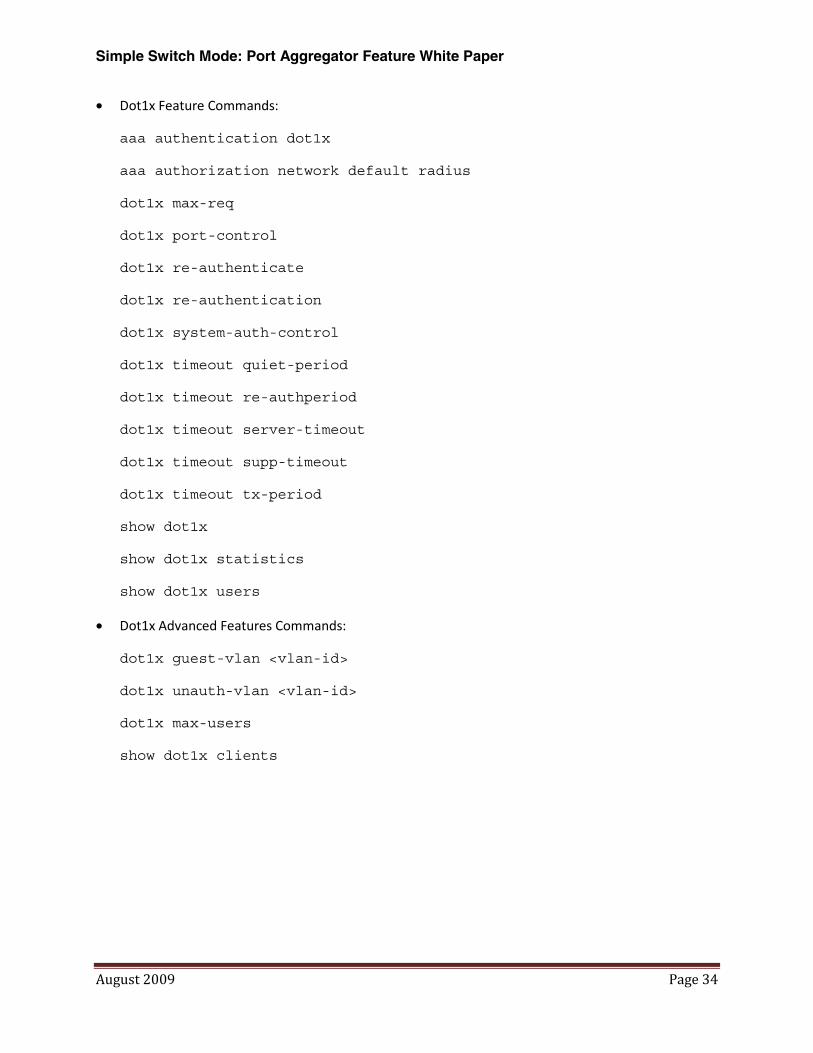
• Dot1x Feature Commands:
aaa authentication dot1x
aaa authorization network default radius
dot1x max-req
dot1x port-control
dot1x re-authenticate
dot1x re-authentication
dot1x system-auth-control
dot1x timeout quiet-period
dot1x timeout re-authperiod
dot1x timeout server-timeout
dot1x timeout supp-timeout
dot1x timeout tx-period
show dot1x
show dot1x statistics
show dot1x users
• Dot1x Advanced Features Commands:
dot1x guest-vlan <vlan-id>
dot1x unauth-vlan <vlan-id>
dot1x max-users
show dot1x clients
Simple Switch Mode: Port Aggregator Feature White Paper
August 2009 Page 35
SNMP Objects
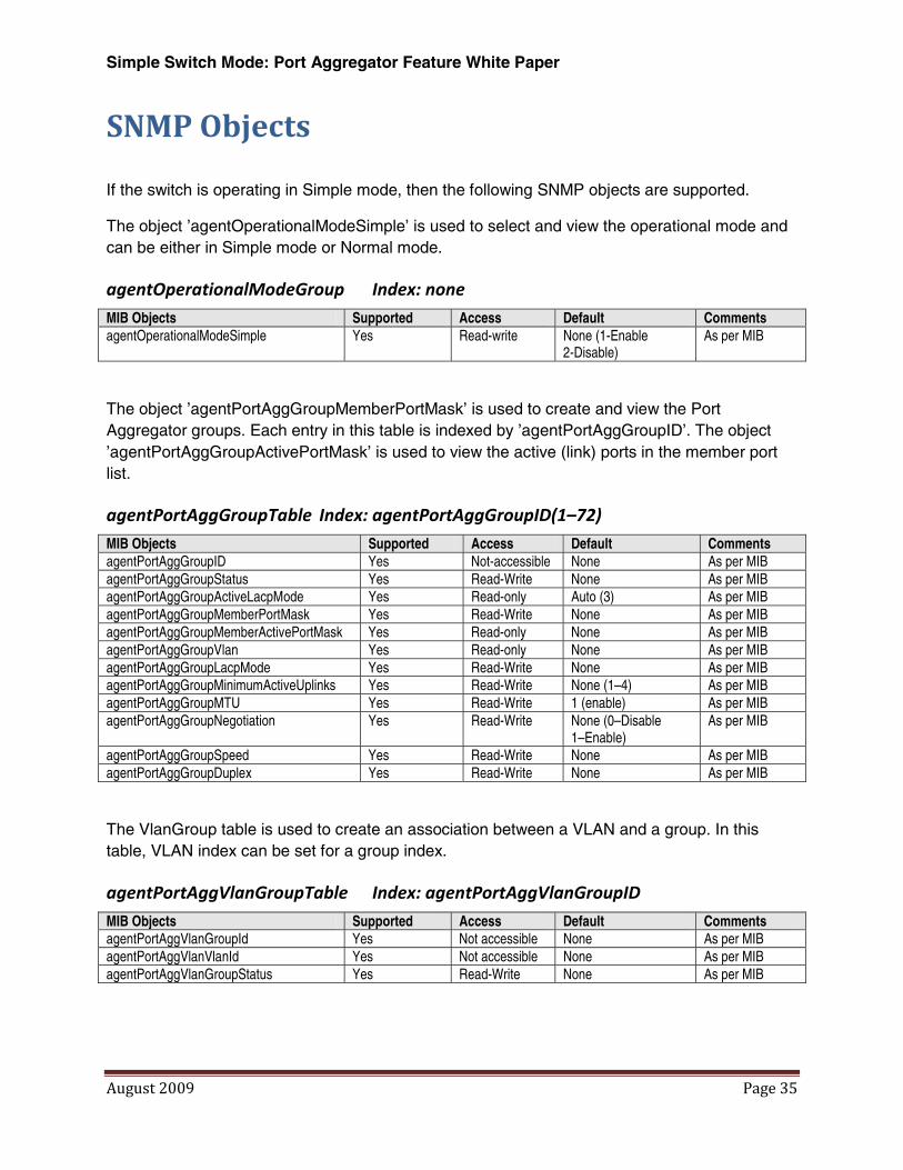
If the switch is operating in Simple mode, then the following SNMP objects are supported.
The object ’agentOperationalModeSimple’ is used to select and view the operational mode and can be either in Simple mode or Normal mode.
agentOperationalModeGroup Index: none
MIB Objects Supported Access Default Comments agentOperationalModeSimple
Yes Read-write None (1-Enable 2-Disable)
As per MIB
The object ’agentPortAggGroupMemberPortMask’ is used to create and view the Port Aggregator groups. Each entry in this table is indexed by ’agentPortAggGroupID’. The object ’agentPortAggGroupActivePortMask’ is used to view the active (link) ports in the member port list.
agentPortAggGroupTable Index: agentPortAggGroupID(1–72)
MIB Objects Supported Access Default Comments agentPortAggGroupID Yes Not-accessible None As per MIB agentPortAggGroupStatus Yes Read-Write None As per MIB agentPortAggGroupActiveLacpMode Yes Read-only Auto (3) As per MIB agentPortAggGroupMemberPortMask Yes Read-Write None As per MIB agentPortAggGroupMemberActivePortMask Yes Read-only None As per MIB agentPortAggGroupVlan Yes Read-only None As per MIB agentPortAggGroupLacpMode Yes Read-Write None As per MIB agentPortAggGroupMinimumActiveUplinks Yes Read-Write None (1–4) As per MIB agentPortAggGroupMTU Yes Read-Write 1 (enable) As per MIB agentPortAggGroupNegotiation Yes Read-Write None (0–Disable
1–Enable) As per MIB
agentPortAggGroupSpeed Yes Read-Write None As per MIB agentPortAggGroupDuplex Yes Read-Write None As per MIB
The VlanGroup table is used to create an association between a VLAN and a group. In this table, VLAN index can be set for a group index.
agentPortAggVlanGroupTable Index: agentPortAggVlanGroupID
MIB Objects Supported Access Default Comments agentPortAggVlanGroupId Yes Not accessible None As per MIB agentPortAggVlanVlanId Yes Not accessible None As per MIB agentPortAggVlanGroupStatus Yes Read-Write None As per MIB

Simple Switch Mode: Port Aggregator Feature White Paper
August 2009 Page 36
In addition to the Port-Aggregator feature’s specific objects, the following SNMP MIB/objects are available in Simple mode:
SNMP MIBs Description MIB Objects FASTPATH-TIMEZONE-PRIVATE-MIB
The Timezone MIB for System TimeZone and SummerTime
fastPathtimeZonePrivate
RFC 1907 - SNMPv2-MIB The MIB module for SNMPv2 entities snmpMIB RFC 2819 - RMON-MIB Remote Network Monitoring Management Information Base rmonMibModule SNMP-COMMUNITY-MIB This MIB module defines objects to help support coexistence
between SNMPv1, SNMPv2, and SNMPv3. snmpCommunityMIB
SNMP-FRAMEWORK-MIB The SNMP Management Architecture MIB snmpFrameworkMIB SNMP-MPD-MIB The MIB for Message Processing and Dispatching snmpMPDMIB SNMP-TARGET-MIB The Target MIB Module snmpTargetMIB RFC 1213 - RFC1213-MIB Management Information Base for Network Management of
TCP/IP-based Internets: MIB-II
mib-2 system .1.3.6.1.2.1.1 interfaces .1.3.6.1.2.1.2 at.1.3.6.1.2.1.3 ip .1.3.6.1.2.1.4 icmp .1.3.6.1.2.1.5 tcp .1.3.6.1.2.1.6 udp .1.3.6.1.2.1.7 egp .1.3.6.1.2.1.8 transmission .1.3.6.1.2.1.10 snmp .1.3.6.1.2.1.11
RFC 2737 - ENTITY-MIB Entity MIB (Version 2) entityMIB RFC 2863 - IF-MIB The Interfaces Group MIB using SMIv2 ifMIB RFC 3635 - Etherlike-MIB
Definitions of Managed Objects for the Ethernet-like Interface Types
etherMIB
FASTPATH-SWITCHING-MIB
FASTPATH Switching - Layer 2
fastPathSwitching agentInfoGroup agentInventoryGroup agentTrapLogGroup agentSupportedMibTable agentSwitchCpuProcessGroup agentConfigGroup agentCLIConfigGroup agentNetworkConfigGroup agentServicePortConfigGroup agentSnmpConfigGroup agentTransferConfigGroup agentAuthenticationGroup agentSystemGroup fastPathSwitchingTraps
FASTPATH-INVENTORY-MIB
Unit and Slot configuration
fastPathInventory
FASTPATH-RADIUS-MIB The Broadcom Private MIB for FASTPATH Radius fastPathRadius RADIUS-AUTH-CLIENT-MIB RADIUS Authentication Client MIB radiusAuthClientMIB FASTPATH-MGMT-SECURITY-MIB
The Broadcom Private MIB for FASTPATH Mgmt Security
fastPathMgmtSecurity
Dell-Vendor-MIB
The private MIB module definition for the Dell PowerConnect Devices. This MIB allows PowerConnect devices to be integrated into the Dell ITA management system.
powerConnectVendorMIB
FASTPATH-LOGGING Log management MIB fastPathLogging
Simple Switch Mode: Port Aggregator Feature White Paper
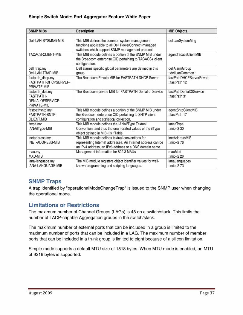
August 2009 Page 37
SNMP MIBs Description MIB Objects Dell-LAN-SYSMNG-MIB
This MIB defines the common system management functions applicable to all Dell PowerConnect-managed switches which support SNMP management protocol.
dellLanSystemMng
TACACS-CLIENT-MIB
This MIB module defines a portion of the SNMP MIB under the Broadcom enterprise OID pertaining to TACACS+ client configuration.
agentTacacsClientMIB
dell_trap.my Dell-LAN-TRAP-MIB
Dell alarms specific global parameters are defined in this group.
dellAlarmGroup ::dellLanCommon 1
fastpath_dhcp.my FASTPATH-DHCPSERVER-PRIVATE-MIB
The Broadcom Private MIB for FASTPATH DHCP Server
fastPathDHCPServerPrivate ::fastPath 12
fastpath_dos.my FASTPATH-DENIALOFSERVICE-PRIVATE-MIB
The Broadcom private MIB for FASTPATH Denial of Service
fastPathDenialOfService ::fastPath 31
fastpathsntp.my FASTPATH-SNTP-CLIENT.MIB
This MIB module defines a portion of the SNMP MIB under the Broadcom enterprise OID pertaining to SNTP client configuration and statistical collection.
agentSntpClientMIB ::fastPath 17
iftype.my IANAifType-MIB
This MIB module defines the IANAifType Textual Convention, and thus the enumerated values of the ifType object defined in MIB-II’s ifTable.
ianaifType ::mib–2 30
inetaddress.my INET-ADDRESS-MIB
This MIB module defines textual conventions for representing Internet addresses. An Internet address can be an IPv4 address, an IPv6 address or a DNS domain name.
inetAddressMIB ::mib–2 76
mau.my MAU-MIB
Management information for 802.3 MAUs mauMod ::mib–2 26
iana-language.my IANA-LANGUAGE-MIB
The MIB module registers object identifier values for well-known programming and scripting languages.
ianaLanguages ::mib–2 73
SNMP Traps A trap identified by "operationalModeChangeTrap" is issued to the SNMP user when changing the operational mode.
Limitations or Restrictions The maximum number of Channel Groups (LAGs) is 48 on a switch/stack. This limits the number of LACP-capable Aggregation groups in the switch/stack.
The maximum number of external ports that can be included in a group is limited to the maximum number of ports that can be included in a LAG. The maximum number of member ports that can be included in a trunk group is limited to eight because of a silicon limitation.
Simple mode supports a default MTU size of 1518 bytes. When MTU mode is enabled, an MTU of 9216 bytes is supported.