how the sparc t4 processor optimizes throughput ... the sparc t4 processor optimizes throughput...
TRANSCRIPT

An Oracle Technical White Paper April 2012
How the SPARC T4 Processor Optimizes Throughput Capacity: A Case Study
How the SPARCT4 Processor Optimizes Throughput Capacity: A Case Study
Introduction ....................................................................................... 1 Summary of the Performance Results ............................................... 4 Performance Characteristics of the CSP1 and CSP2 Programs ........ 5
The UltraSPARC T2+ Pipeline Architecture ................................... 5 Instruction Scheduling Analysis for the CSP1 Program on the UltraSPARC T2+ Processor .......................................................... 6 Instruction Scheduling Analysis for the CSP2 Program on the UltraSPARC T2+ Processor .......................................................... 9
UltraSPARC T2+ Performance Results ........................................... 10 Test Framework........................................................................... 10 UltraSPARC T2+ Performance Results for the CSP1 Program .... 11 UltraSPARC T2+ Performance Results for the CSP2 Program .... 12
SPARC T4 Performance Results ..................................................... 13 Summary of the SPARC T4 Core Architecture ............................ 13 Test Framework........................................................................... 15 Cycle Count Estimates and Performance Results for the CSP1 Program on the SPARC T4 Processor ......................................... 15 Cycle Count Estimates and Performance Results for the CSP2 Program on the SPARC T4 Processor ......................................... 17
Acknowledgements ......................................................................... 18 References ...................................................................................... 19 About the Authors ............................................................................ 19
How the SPARCT4 Processor Optimizes Throughput Capacity: A Case Study
1
Introduction
This white paper demonstrates the architected latency hiding features of Oracle’s UltraSPARC T2+ and SPARC T4 processors.
Latency is the time delay between when a request is sent and the moment the result of the request is delivered. Such delays can be found between many components within a computer system and can have a significant impact on performance.
In this paper, the focus is on instruction-level latencies, which are usually expressed in processor cycles. Many instructions have a fixed latency, but there are also instructions with a latency that depends on the runtime conditions or data type format.
An example is a load instruction to fetch data from memory. If the data is in the first-level data cache, the time to access it is just a few processor cycles. If however the data has to come from far away in the system, such as from main memory, it can take hundreds of cycles.
The problem with latency is that it creates what is called a gap or bubble in the processor’s execution pipelines. While the processor is waiting for an instruction to complete, for example, for data to be fetched through a load instruction, cycles are wasted. This reduces the performance of the application and also results in a loss of system throughput capacity, because fewer jobs can be completed per unit of time.
Luckily, in many cases there are hardware features and software optimization techniques for reducing latency. Caches are a good example. By keeping frequently used data in a cache, access times are reduced.
How the SPARCT4 Processor Optimizes Throughput Capacity: A Case Study
2
In addition to the use of caches the performance of the memory system can be further enhanced through a mechanism called prefetching. With prefetching the processor fetches data ahead of its expected use and places it in a fast storage location, such as a cache. This action typically overlaps with another activity in the processor. It is most effective on data that is relatively far away and therefore expensive to access.
Prefetching masks (a part of) the cost of the load instruction and reduces the waiting time. The net benefit is a reduced latency of the load instruction fetching the data. This feature is implemented on many modern processors and an example of what is generally referred to as latency hiding.
What, however, if these features and techniques have a limited impact, or worse, if they cannot be successfully applied at all?
For example, what if the memory access pattern of an application is random? The benefit of caches is limited and prefetching cannot detect a data access pattern because there is none. It is also impossible for optimizing compilers to fix this situation. As a result, a load instruction takes a long time, and the processor burns many cycles waiting for the data to arrive.
Or, what if an application uses a fixed, but long, latency instruction (such as a divide) that takes a significant number of cycles to complete? These are just two scenarios where things don’t work out well. There is nothing else to do other than accept a loss in performance and capacity.
Or, is there a solution?
Why not use these gaps to execute instructions from another application or a different thread from the same application? In doing so, the overall utilization of the system is improved because processor cycles are no longer wasted.
How the SPARCT4 Processor Optimizes Throughput Capacity: A Case Study
3
This is exactly what latency hiding in Oracle’s SPARC T-Series processors has done from day one.
To see how this works at the application level and in what way the hardware (transparently to the application and user) automatically maximizes the use of available processor cycles to improve the total system throughput, read on!
How the SPARCT4 Processor Optimizes Throughput Capacity: A Case Study
4
Summary of the Performance Results
For this paper, a series of performance experiments was performed that used two integer programs written in C.
The purpose of these experiments is to demonstrate the architected latency hiding features of the UltraSPARC T2+ and SPARC T4 processors.
The first program is called CSP1. It has a tight loop with minimal work per pass. On the UltraSPARC T2+ processor, the instruction schedule is largely dominated by the six to seven processor cycles needed by the branch instruction. This leads to idle cycles in the pipeline.
Due to several major architectural enhancements, the instruction schedule on the SPARC T4 processor does not have such gaps. The improvements cause the single-thread performance of CSP1 on the SPARC T4 processor to be 8.5 times higher than on the UltraSPARC T2+ processor.
The second program is called CSP2. Its performance is dominated by the cost of the integer subtraction instruction, which is one cycle on both processors. Due to a data dependence in the program, only one integer subtraction can be performed per cycle per thread. This means the application cannot take advantage of the dual instruction execution feature of the SPARC T4 processor. Therefore, the performance gain on the SPARC T4 processor is only proportional to the increase in clock speed.
For both programs, not only was the performance of a single copy of the program evaluated, but the throughput performance when simultaneously running multiple copies of the same program was measured as well. This was done for an increasing number of copies, thereby increasing the workload.
The throughput results are not necessarily what you might expect at first sight, but taking the assembly code generated by the compiler and the processor architectures into account, all measured results turn out to be predictable.
For up to 16 simultaneous copies, the 16 pipelines in the UltraSPARC T2+ processor are used to execute one copy each. Beyond this, the gaps in the instruction schedule are gradually filled, resulting in improved utilization of the system. As a result, overall processor utilization increases and the total time for a workload grows less than linearly as the number of copies increases. When executing 64 copies, all gaps are filled and from there on, the execution time increases linearly when doubling the load.
On the SPARC T4 processor, there are no gaps in the schedule to be filled and the execution time for one to eight copies of CSP1 is the same, because the load is spread across the pipelines in the processor. Beyond this, the total time to execute the workload scales linearly with the number of simultaneous copies.
On both processors, the CSP2 program has few gaps in the execution schedule. Due to the data dependence, only one result per clock cycle per thread can be delivered. In both cases, executing up to 16 copies simultaneously takes the same number of processor cycles per copy, but since the clock speed of the SPARC T4 processor is much higher, the total time is much less on this processor. For a higher load, the execution time scales linearly with the number of copies executed.
How the SPARCT4 Processor Optimizes Throughput Capacity: A Case Study
5
Performance Characteristics of the CSP1 and CSP2 Programs
One of the key architectural features of all SPARC T-series processors is the ability to very efficiently hide the latency of multicycle1 instructions by filling otherwise-idle instruction slots with instructions from other processes or threads from the same application.
This is dynamic and transparent to the application and operating system. For example, if a data item requested is not in the L2 data cache of the core, the data has to come from further away in the memory hierarchy. In a more conventional design, this causes the processor to be idle while waiting for the data to arrive. In the SPARC T-series processors, other processes or threads can use these idle cycles.
The performance benefits that are realized depend on the instruction characteristics of the applications that are executed, but since most applications can’t keep all pipelines busy all the time, the total throughput capacity of the processor is enhanced for most workloads.
The two C programs, CSP1 and CSP2, demonstrate this instruction latency hiding feature of the SPARC T-series processors. Both programs perform the same type of integer subtractions in a while loop structure, but they are implemented in different ways.
As we will see, the different implementations lead to demonstrably different performance characteristics.
The UltraSPARC T2+ Pipeline Architecture
Before presenting the instruction scheduling analysis and performance results for both programs, the pipeline architecture of the UltraSPARC T2+ processor [1][2] is briefly summarized.
An UltraSPARC T2+ processor has eight cores. Each core has two integer execution pipelines, both supporting four threads. There are two additional pipelines, one for floating-point/graphics instructions plus a load-store pipeline for memory operations, but these pipelines are shared among the eight threads within the core. For the purpose of this study, we focus on the integer pipelines.
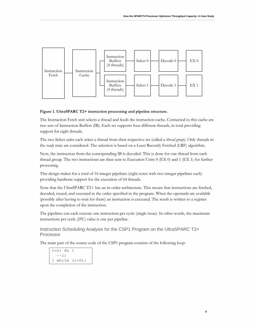
Figure 1 shows a partial block diagram of the UltraSPARC T2+ processor.
1 On a processor with a clock frequency of 1 GHz, one cycle takes one nanosecond (10-9-th of a second).
How the SPARCT4 Processor Optimizes Throughput Capacity: A Case Study
6
Figure 1. UltraSPARC T2+ instruction processing and pipeline structure.
The Instruction Fetch unit selects a thread and feeds the instruction cache. Connected to this cache are two sets of Instruction Buffers (IB). Each set supports four different threads, in total providing support for eight threads.
The two Select units each select a thread from their respective set (called a thread group). Only threads in the ready state are considered. The selection is based on a Least Recently Fetched (LRF) algorithm.
Next, the instruction from the corresponding IB is decoded. This is done for one thread from each thread group. The two instructions are then sent to Execution Units 0 (EX 0) and 1 (EX 1) for further processing.
This design makes for a total of 16 integer pipelines (eight cores with two integer pipelines each) providing hardware support for the execution of 64 threads.
Note that the UltraSPARC T2+ has an in-order architecture. This means that instructions are fetched, decoded, issued, and executed in the order specified in the program. When the operands are available (possibly after having to wait for them) an instruction is executed. The result is written to a register upon the completion of the instruction.
The pipelines can each execute one instruction per cycle (single issue). In other words, the maximum instructions per cycle (IPC) value is one per pipeline.
Instruction Scheduling Analysis for the CSP1 Program on the UltraSPARC T2+ Processor
The main part of the source code of the CSP1 program consists of the following loop:
i=n; do { --i; } while (i>0);
Instruction Fetch
Instruction Cache
Instruction Buffers
(4 threads) Select 0 Decode 0 EX 0
Instruction Buffers
(4 threads) Select 1 Decode 1 EX 1
How the SPARCT4 Processor Optimizes Throughput Capacity: A Case Study
7
This program was compiled without any optimizations enabled on the Oracle Solaris Studio C compiler [3]. In general, we recommend using optimization since, most likely, a significant performance penalty is paid if the compiler is not allowed to optimize the code.
In this case, however, the code is used to highlight the behavior with simple loops. Even with modest optimization enabled in the compiler, the entire loop is eliminated because the compiler can statically determine the result without executing the loop.
The loop above in CSP1 translates into the following sequence of four instructions: .L21: sub %i4,1,%i4 cmp %i4,0 bg .L21 nop
On the UltraSPARC T2+ processor, the integer subtraction (sub) and compare (cmp) instructions take one cycle each. The branch (bg) instruction takes six to seven cycles. The reason this is not a single number is because, in some cases, the cost could be seven cycles depending on the state of the instruction-handling part of the core.
The no-operation (nop) instruction after the branch is used to fill the delay slot after the bg instruction. The branch delay slot is required by the SPARC instruction set architecture and, in this case, it is always executed, regardless of the preceding instruction. The nop instruction is considered to be part of the complete loop, but it does not add an additional cycle to the cost of the branch. If instructions from other threads (or processes) are available, the pipeline executes them immediately following the branch.
As a result of these instruction characteristics on the UltraSPARC T2+ processor, this schedule takes eight to nine cycles per pass through the loop in the CSP1 program.
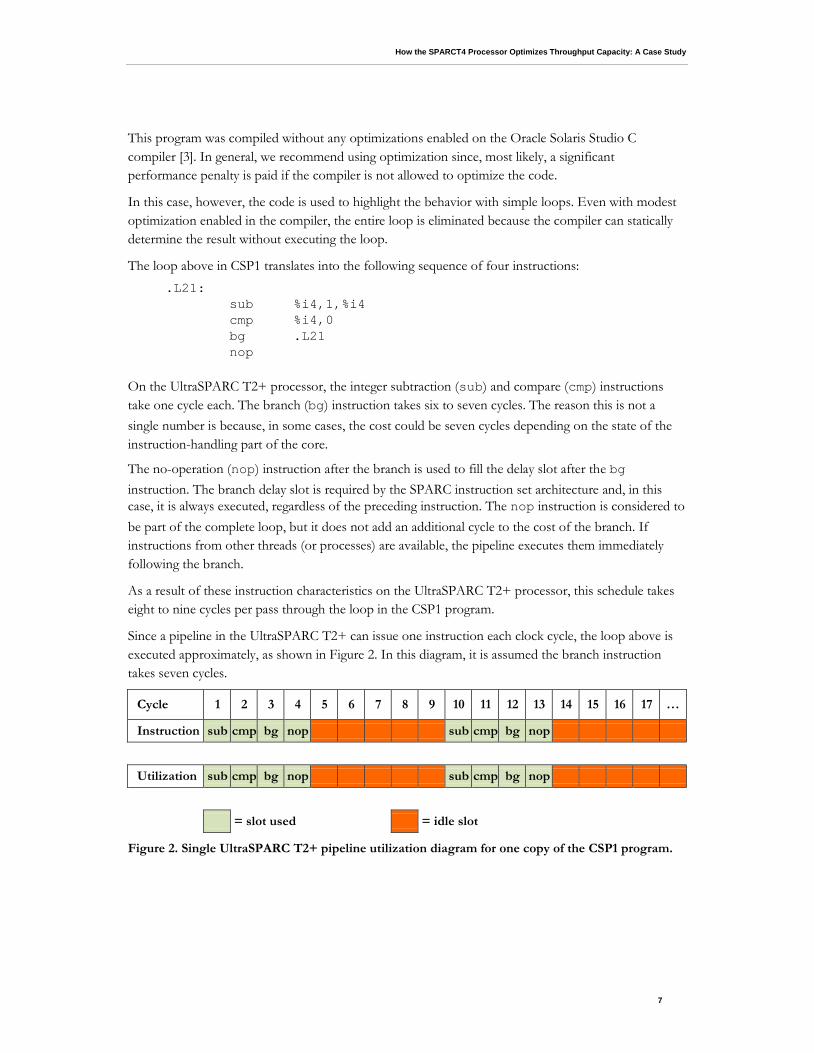
Since a pipeline in the UltraSPARC T2+ can issue one instruction each clock cycle, the loop above is executed approximately, as shown in Figure 2. In this diagram, it is assumed the branch instruction takes seven cycles.
Figure 2. Single UltraSPARC T2+ pipeline utilization diagram for one copy of the CSP1 program.
Cycle 1 2 3 4 5 6 7 8 9 10 11 12 13 14 15 16 17 …
Instruction sub cmp bg nop sub cmp bg nop
Utilization sub cmp bg nop sub cmp bg nop
= slot used = idle slot

How the SPARCT4 Processor Optimizes Throughput Capacity: A Case Study
8
The top row labeled “Cycle” shows the time passed expressed in processor cycles. The second row (“Instruction”) shows what instruction is executed. The last row (“Utilization”) shows the total pipeline utilization. Light green means the slot can be used, whereas dark orange indicates no instruction is issued in the corresponding cycle.
We see in this diagram that five out of the nine cycles (56 percent) in the pipeline are not utilized.
As mentioned earlier, a key feature of the SPARC T-Series processors is that they can very efficiently execute multiple processes or threads simultaneously. Other processes fill idle cycles caused by the instruction and execution characteristics of a process. This maximizes the pipeline utilization.
For example, if we were to run two copies of CSP1 on the same pipeline, the execution schedule will be as shown in Figure 3. Note that the diagram reflects the Least Recently Fetched (LRF) scheduling of threads.
Figure 3. Single UltraSPARC T2+ pipeline utilization diagram for two copies of the CSP1 program.
When executing two copies (or threads of the same parallel application) simultaneously, the pipeline can be utilized more efficiently. The two copies now execute in 11 cycles (a 22 percent increase), but the idle time is reduced to 27 percent. In other words, within each window of 11 cycles, there are three more slots left for additional copies (or other applications, for that matter) to take advantage of.
Note that this is transparent to the application, and there is no penalty for switching among active threads. It is all handled in the hardware and no user action is needed.
We want to point out that a more compact schedule could be generated. The cmp %i4,0 instruction is a synthetic instruction, mapping to the subcc (subtract and modify condition codes) instruction. In this case, it stands for the subcc %i4,0,%g0 instruction.
The sub and cmp instructions can be combined, though, and only one subcc instruction is needed, resulting in the following schedule:
.L21: subcc %i4,1,%i4 bg .L21 nop
Cycle 1 2 3 4 5 6 7 8 9 10 11 12 13 14 15 16 17 …
Thread 0 sub cmp bg nop sub cmp bg nop
Thread 1 sub cmp bg nop sub cmp bg
Utilization sub sub cmp cmp bg bg nop nop sub sub cmp cmp bg bg nop
= slot used = idle slot
How the SPARCT4 Processor Optimizes Throughput Capacity: A Case Study
9
This saves one cycle on the UltraSPARC T2+ processor. The compiler does not, however, generate this more compact schedule because optimization has not been enabled.
Instruction Scheduling Analysis for the CSP2 Program on the UltraSPARC T2+ Processor
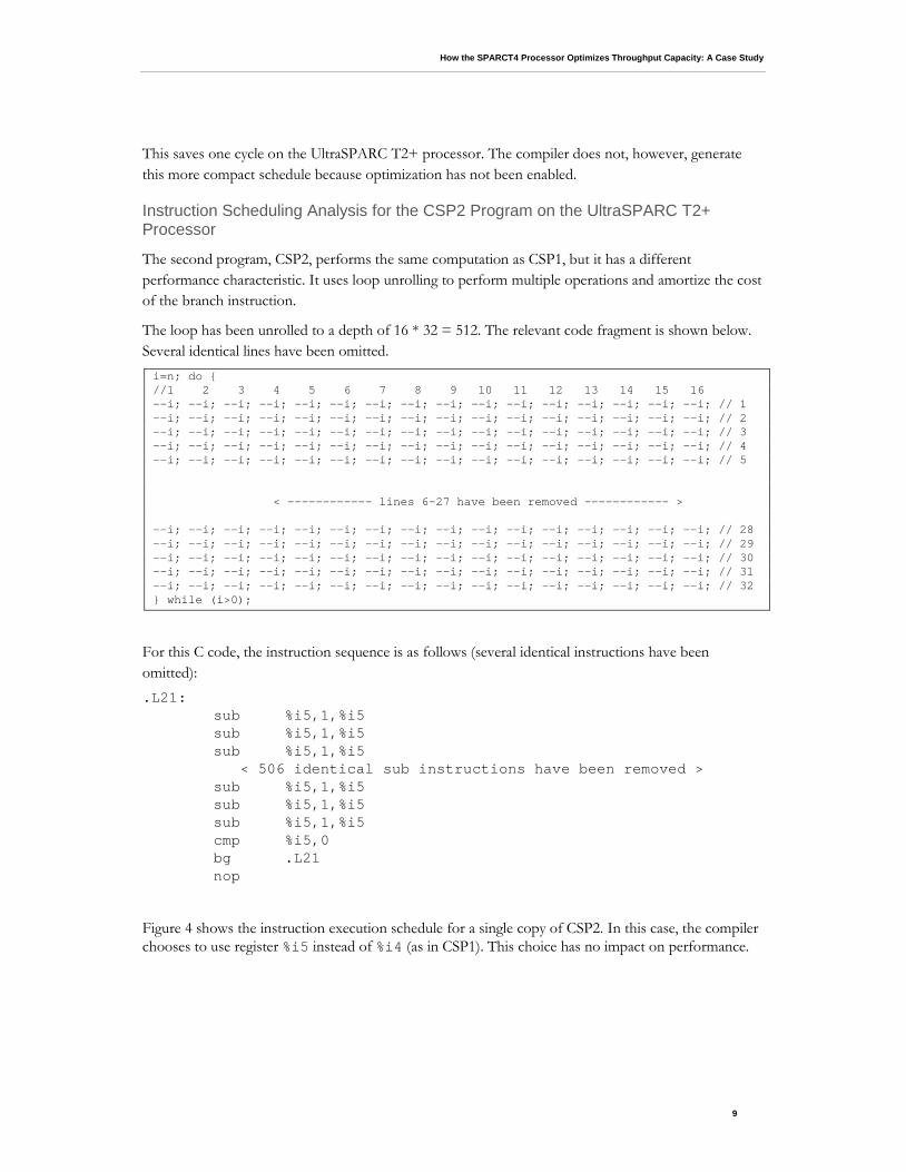
The second program, CSP2, performs the same computation as CSP1, but it has a different performance characteristic. It uses loop unrolling to perform multiple operations and amortize the cost of the branch instruction.
The loop has been unrolled to a depth of 16 * 32 = 512. The relevant code fragment is shown below. Several identical lines have been omitted. i=n; do { //1 2 3 4 5 6 7 8 9 10 11 12 13 14 15 16 --i; --i; --i; --i; --i; --i; --i; --i; --i; --i; --i; --i; --i; --i; --i; --i; // 1 --i; --i; --i; --i; --i; --i; --i; --i; --i; --i; --i; --i; --i; --i; --i; --i; // 2 --i; --i; --i; --i; --i; --i; --i; --i; --i; --i; --i; --i; --i; --i; --i; --i; // 3 --i; --i; --i; --i; --i; --i; --i; --i; --i; --i; --i; --i; --i; --i; --i; --i; // 4 --i; --i; --i; --i; --i; --i; --i; --i; --i; --i; --i; --i; --i; --i; --i; --i; // 5 < ------------ lines 6-27 have been removed ------------ > --i; --i; --i; --i; --i; --i; --i; --i; --i; --i; --i; --i; --i; --i; --i; --i; // 28 --i; --i; --i; --i; --i; --i; --i; --i; --i; --i; --i; --i; --i; --i; --i; --i; // 29 --i; --i; --i; --i; --i; --i; --i; --i; --i; --i; --i; --i; --i; --i; --i; --i; // 30 --i; --i; --i; --i; --i; --i; --i; --i; --i; --i; --i; --i; --i; --i; --i; --i; // 31 --i; --i; --i; --i; --i; --i; --i; --i; --i; --i; --i; --i; --i; --i; --i; --i; // 32 } while (i>0);
For this C code, the instruction sequence is as follows (several identical instructions have been omitted): .L21: sub %i5,1,%i5 sub %i5,1,%i5 sub %i5,1,%i5 < 506 identical sub instructions have been removed > sub %i5,1,%i5 sub %i5,1,%i5 sub %i5,1,%i5 cmp %i5,0 bg .L21 nop
Figure 4 shows the instruction execution schedule for a single copy of CSP2. In this case, the compiler chooses to use register %i5 instead of %i4 (as in CSP1). This choice has no impact on performance.
How the SPARCT4 Processor Optimizes Throughput Capacity: A Case Study
10
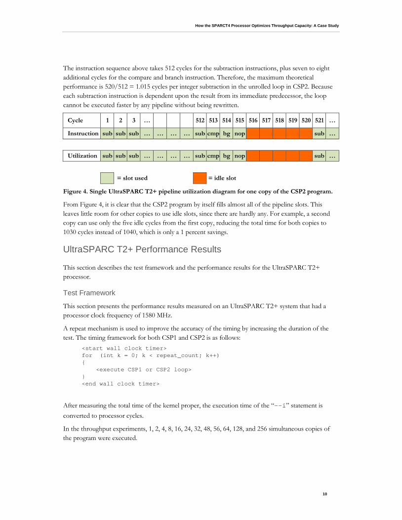
The instruction sequence above takes 512 cycles for the subtraction instructions, plus seven to eight additional cycles for the compare and branch instruction. Therefore, the maximum theoretical performance is 520/512 = 1.015 cycles per integer subtraction in the unrolled loop in CSP2. Because each subtraction instruction is dependent upon the result from its immediate predecessor, the loop cannot be executed faster by any pipeline without being rewritten.
Figure 4. Single UltraSPARC T2+ pipeline utilization diagram for one copy of the CSP2 program.
From Figure 4, it is clear that the CSP2 program by itself fills almost all of the pipeline slots. This leaves little room for other copies to use idle slots, since there are hardly any. For example, a second copy can use only the five idle cycles from the first copy, reducing the total time for both copies to 1030 cycles instead of 1040, which is only a 1 percent savings.
UltraSPARC T2+ Performance Results
This section describes the test framework and the performance results for the UltraSPARC T2+ processor.
Test Framework
This section presents the performance results measured on an UltraSPARC T2+ system that had a processor clock frequency of 1580 MHz.
A repeat mechanism is used to improve the accuracy of the timing by increasing the duration of the test. The timing framework for both CSP1 and CSP2 is as follows:
<start wall clock timer> for (int k = 0; k < repeat_count; k++) { <execute CSP1 or CSP2 loop> } <end wall clock timer>
After measuring the total time of the kernel proper, the execution time of the “--i” statement is converted to processor cycles.
In the throughput experiments, 1, 2, 4, 8, 16, 24, 32, 48, 56, 64, 128, and 256 simultaneous copies of the program were executed.
Cycle 1 2 3 … 512 513 514 515 516 517 518 519 520 521 …
Instruction sub sub sub … … … … sub cmp bg nop sub …
Utilization sub sub sub … … … … sub cmp bg nop sub …
= slot used = idle slot
How the SPARCT4 Processor Optimizes Throughput Capacity: A Case Study
11
The UltraSPARC T2+ system used in the tests had four processors, but through the use of a processor set, we ensured only one processor was used. Similar results can be obtained using all four processors.
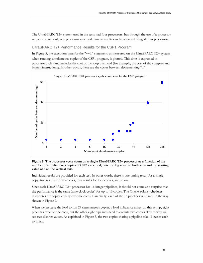
UltraSPARC T2+ Performance Results for the CSP1 Program In Figure 5, the execution time for the "--i” statement, as measured on the UltraSPARC T2+ system when running simultaneous copies of the CSP1 program, is plotted. This time is expressed in processor cycles and includes the cost of the loop overhead (for example, the cost of the compare and branch instructions). In other words, these are the cycles between decrementing “i”.
Figure 5. The processor cycle count on a single UltraSPARC T2+ processor as a function of the number of simultaneous copies of CSP1 executed; note the log scale on both axes and the starting value of 8 on the vertical axis.
Individual results are provided for each test. In other words, there is one timing result for a single copy, two results for two copies, four results for four copies, and so on.
Since each UltraSPARC T2+ processor has 16 integer pipelines, it should not come as a surprise that the performance is the same (nine clock cycles) for up to 16 copies. The Oracle Solaris scheduler distributes the copies equally over the cores. Essentially, each of the 16 pipelines is utilized in the way shown in Figure 2.
When we increase the load to run 24 simultaneous copies, a load imbalance arises. In this set up, eight pipelines execute one copy, but the other eight pipelines need to execute two copies. This is why we see two distinct values. As explained in Figure 3, the two copies sharing a pipeline take 11 cycles each to finish.
8
16
32
64
1 2 4 8 16 32 64 128 256
Num
ber o
f cyc
les
betw
een
decr
emen
ting
i
Number of simultaneous copies
Single UltraSPARC T2+ processor cycle count cost for the CSP1 program
How the SPARCT4 Processor Optimizes Throughput Capacity: A Case Study
12
With a workload of 32 copies, each copy takes the same amount of time again, because all pipelines are utilized in the same balanced way. The cycle count goes up to 12, but that is most likely caused by operating system context switching, since we did not bind the processes to hardware threads.
As was also demonstrated in Figure 3, there are still idle cycles left to take advantage of and clearly this is the case when executing 48 copies simultaneously. Even though the load increases by 50 percent (48 copies instead of 32), the execution time for each copy does not increase. This is instruction latency hiding at work!
Once the load goes up to 56 copies, we again see that some copies take longer than others. This is because of another load imbalance. Now eight pipelines execute three copies each, but the other eight pipelines need to execute four copies.
For 64 copies, the load is equally balanced again, but by now there are no more gaps in the pipeline to be filled and the cycle count goes up to 16.
This in itself demonstrates the strength of the SPARC T-series architecture. A 64x higher load increases the total execution time by a factor of only 16/9 = 1.78.
As seen, the performance scales linearly when increasing the load above 64. When doubling the load to 128 simultaneous copies, the cycle count goes up to 32. Doubling the workload again to 256 jobs gives a cycle count of 64.
Note that in a few places, the marker in the plot seems to be blurred. This is because sometimes the cycle count for the same experiment (for example, for 128 simultaneous copies) slightly varies and all values are plotted. Recall that the branch instruction on the UltraSPARC T2+ processor can take six to seven cycles depending on the state the pipeline is in.
On top of that, there are operating system context switches, because the pipelines are (heavily) oversubscribed as we increase the load. It is, therefore, no surprise that sometimes our experiments produce more than one cycle count per experiment, but in all cases the difference is in the single-digit percentage range.
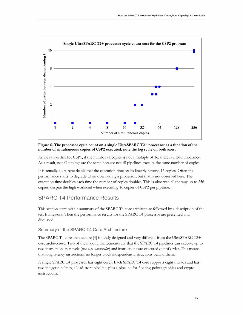
UltraSPARC T2+ Performance Results for the CSP2 Program Figure 6 plots the execution time for the “--i” statement as measured on the UltraSPARC T2+ processor when running multiple simultaneous copies of the CSP2 program. The time is expressed in processor cycles and the loop overhead is included in this number. Similarly to the CSP1 program, all individual timing results are plotted for each test.
The performance measured is fairly straightforward and predictable. For up to 16 copies, each copy has a pipeline to itself and, as estimated earlier, indeed delivers a performance of one cycle per decrement of the variable “i” in this unrolled loop.
Since there are practically no idle cycles in the schedule, the performance for a multiple of 16 copies scales linearly. For example, 32 copies take twice as long, 48 copies takes three times as long, and so on.
How the SPARCT4 Processor Optimizes Throughput Capacity: A Case Study
13
Figure 6. The processor cycle count on a single UltraSPARC T2+ processor as a function of the number of simultaneous copies of CSP2 executed; note the log scale on both axes.
As we saw earlier for CSP1, if the number of copies is not a multiple of 16, there is a load imbalance. As a result, not all timings are the same because not all pipelines execute the same number of copies.
It is actually quite remarkable that the execution time scales linearly beyond 16 copies. Often the performance starts to degrade when overloading a processor, but that is not observed here. The execution time doubles each time the number of copies doubles. This is observed all the way up to 256 copies, despite the high workload when executing 16 copies of CSP2 per pipeline.
SPARC T4 Performance Results
This section starts with a summary of the SPARC T4 core architecture followed by a description of the test framework. Then the performance results for the SPARC T4 processor are presented and discussed.
Summary of the SPARC T4 Core Architecture
The SPARC T4 core architecture [4] is newly designed and very different from the UltraSPARC T2+ core architecture. Two of the major enhancements are that the SPARC T4 pipelines can execute up to two instructions per cycle (two-way superscalar) and instructions are executed out of order. This means that long latency instructions no longer block independent instructions behind them.
A single SPARC T4 processor has eight cores. Each SPARC T4 core supports eight threads and has two integer pipelines, a load-store pipeline, plus a pipeline for floating-point/graphics and crypto instructions.
1
2
4
8
16
1 2 4 8 16 32 64 128 256
Num
ber o
f cyc
les
betw
een
decr
emen
ting
i
Number of simultaneous copies
Single UltraSPARC T2+ processor cycle count cost for the CSP2 program
How the SPARCT4 Processor Optimizes Throughput Capacity: A Case Study
14
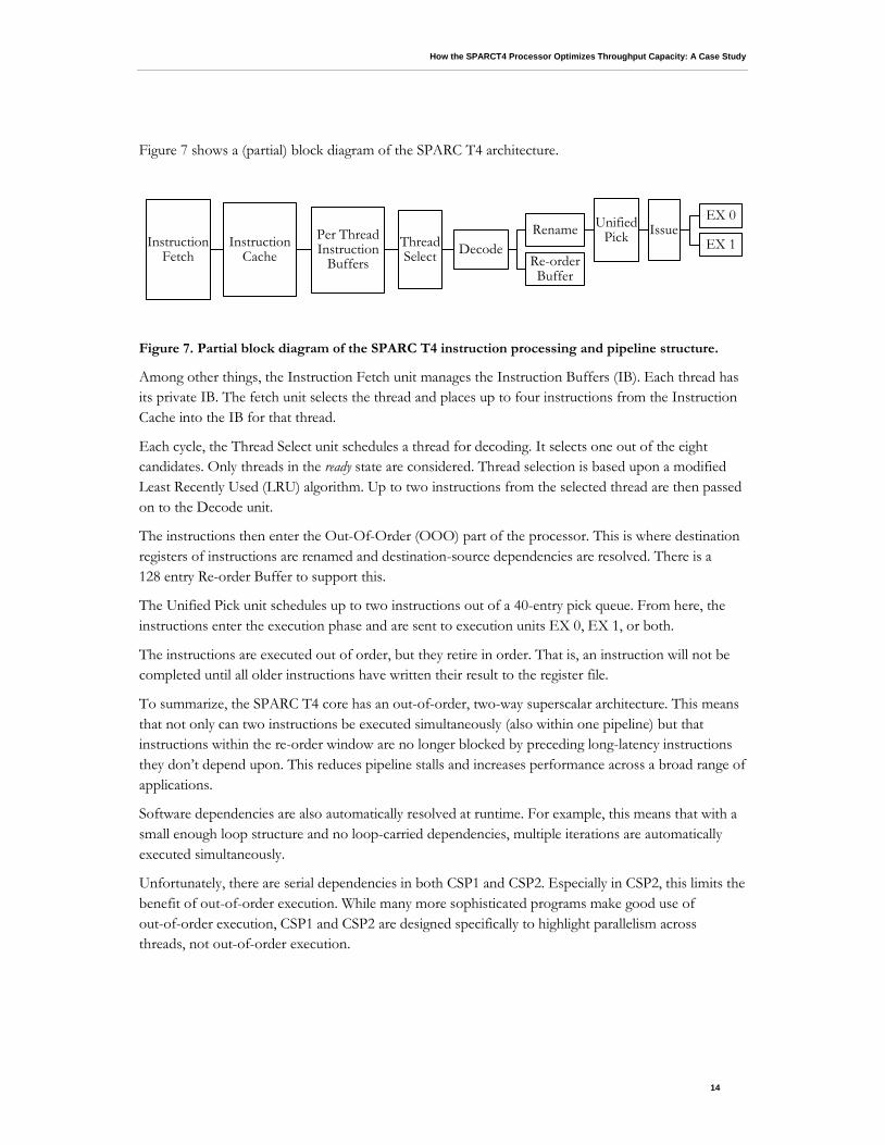
Figure 7 shows a (partial) block diagram of the SPARC T4 architecture.
Figure 7. Partial block diagram of the SPARC T4 instruction processing and pipeline structure.
Among other things, the Instruction Fetch unit manages the Instruction Buffers (IB). Each thread has its private IB. The fetch unit selects the thread and places up to four instructions from the Instruction Cache into the IB for that thread.
Each cycle, the Thread Select unit schedules a thread for decoding. It selects one out of the eight candidates. Only threads in the ready state are considered. Thread selection is based upon a modified Least Recently Used (LRU) algorithm. Up to two instructions from the selected thread are then passed on to the Decode unit.
The instructions then enter the Out-Of-Order (OOO) part of the processor. This is where destination registers of instructions are renamed and destination-source dependencies are resolved. There is a 128 entry Re-order Buffer to support this.
The Unified Pick unit schedules up to two instructions out of a 40-entry pick queue. From here, the instructions enter the execution phase and are sent to execution units EX 0, EX 1, or both.
The instructions are executed out of order, but they retire in order. That is, an instruction will not be completed until all older instructions have written their result to the register file.
To summarize, the SPARC T4 core has an out-of-order, two-way superscalar architecture. This means that not only can two instructions be executed simultaneously (also within one pipeline) but that instructions within the re-order window are no longer blocked by preceding long-latency instructions they don’t depend upon. This reduces pipeline stalls and increases performance across a broad range of applications.
Software dependencies are also automatically resolved at runtime. For example, this means that with a small enough loop structure and no loop-carried dependencies, multiple iterations are automatically executed simultaneously.
Unfortunately, there are serial dependencies in both CSP1 and CSP2. Especially in CSP2, this limits the benefit of out-of-order execution. While many more sophisticated programs make good use of out-of-order execution, CSP1 and CSP2 are designed specifically to highlight parallelism across threads, not out-of-order execution.
Instruction Fetch
Instruction Cache
Per Thread Instruction
Buffers Thread Select Decode
Rename Unified Pick Issue
EX 0
EX 1 Re-order Buffer
How the SPARCT4 Processor Optimizes Throughput Capacity: A Case Study
15
Test Framework
The two programs were executed on a four-processor SPARC T4 system, but through the use of a processor set they were restricted to run on a single processor only. The clock frequency of the processor was 2998 MHz.
For both CSP1 and CSP2, the compiler was instructed to generate exactly the same instruction sequence as for the UltraSPARC T2+ processor. This is because no optimization was specified. Similar to what we saw on the UltraSPARC T2+, even for a modest optimization level, the compiler can statically determine the result without executing the loop.
Cycle Count Estimates and Performance Results for the CSP1 Program on the SPARC T4 Processor
Before we look at the results, let’s first estimate the expected performance using a similar cycle-count diagram as shown earlier for the UltraSPARC T2+ processor.
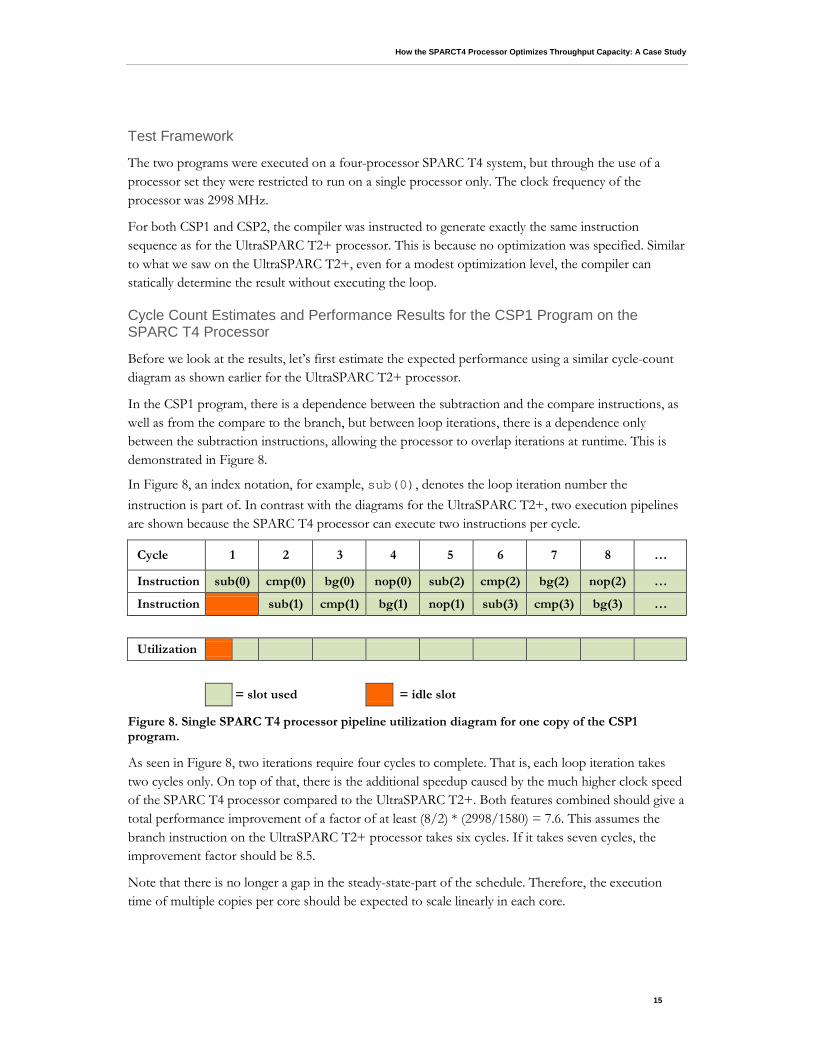
In the CSP1 program, there is a dependence between the subtraction and the compare instructions, as well as from the compare to the branch, but between loop iterations, there is a dependence only between the subtraction instructions, allowing the processor to overlap iterations at runtime. This is demonstrated in Figure 8.
In Figure 8, an index notation, for example, sub(0), denotes the loop iteration number the instruction is part of. In contrast with the diagrams for the UltraSPARC T2+, two execution pipelines are shown because the SPARC T4 processor can execute two instructions per cycle.
Figure 8. Single SPARC T4 processor pipeline utilization diagram for one copy of the CSP1 program.
As seen in Figure 8, two iterations require four cycles to complete. That is, each loop iteration takes two cycles only. On top of that, there is the additional speedup caused by the much higher clock speed of the SPARC T4 processor compared to the UltraSPARC T2+. Both features combined should give a total performance improvement of a factor of at least (8/2) * (2998/1580) = 7.6. This assumes the branch instruction on the UltraSPARC T2+ processor takes six cycles. If it takes seven cycles, the improvement factor should be 8.5.
Note that there is no longer a gap in the steady-state-part of the schedule. Therefore, the execution time of multiple copies per core should be expected to scale linearly in each core.
Cycle 1 2 3 4 5 6 7 8 …
Instruction sub(0) cmp(0) bg(0) nop(0) sub(2) cmp(2) bg(2) nop(2) …
Instruction sub(1) cmp(1) bg(1) nop(1) sub(3) cmp(3) bg(3) …
Utilization
= slot used = idle slot
How the SPARCT4 Processor Optimizes Throughput Capacity: A Case Study
16
Also note that with optimization enabled, the compiler might have generated code using the more efficient cwbg (fused compare-and-branch, a.k.a. CBcond) instruction, which is new for the SPARC T4 processor. This instruction is nondelayed. It makes the nop instruction that was previously needed superfluous and performs the functionality of both the cmp and bg instructions, which results in the following very compact sequence:
.L21: sub %i4,1,%i4 cwbg %i4,0,.L21
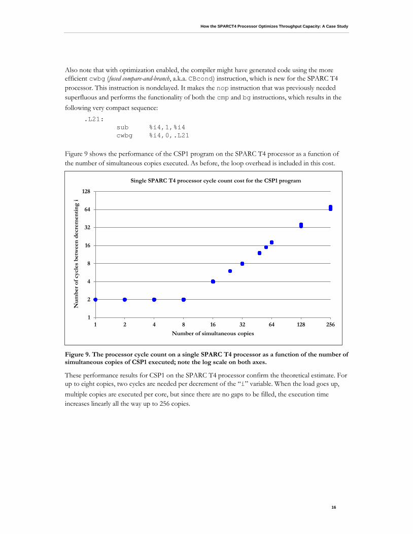
Figure 9 shows the performance of the CSP1 program on the SPARC T4 processor as a function of the number of simultaneous copies executed. As before, the loop overhead is included in this cost.
Figure 9. The processor cycle count on a single SPARC T4 processor as a function of the number of simultaneous copies of CSP1 executed; note the log scale on both axes.
These performance results for CSP1 on the SPARC T4 processor confirm the theoretical estimate. For up to eight copies, two cycles are needed per decrement of the “i” variable. When the load goes up, multiple copies are executed per core, but since there are no gaps to be filled, the execution time increases linearly all the way up to 256 copies.
1
2
4
8
16
32
64
128
1 2 4 8 16 32 64 128 256
Num
ber o
f cyc
les
betw
een
decr
emen
ting
i
Number of simultaneous copies
Single SPARC T4 processor cycle count cost for the CSP1 program
How the SPARCT4 Processor Optimizes Throughput Capacity: A Case Study
17
Note that similarly to the UltraSPARC T2+ results, we see a little blurring, but in this case, this is only when running 128 or 256 simultaneous copies. In both cases, the cycle count has a maximum difference of two. Given the very high workload, we suspect operating system context switches are the cause of these very small variations.
Cycle Count Estimates and Performance Results for the CSP2 Program on the SPARC T4 Processor
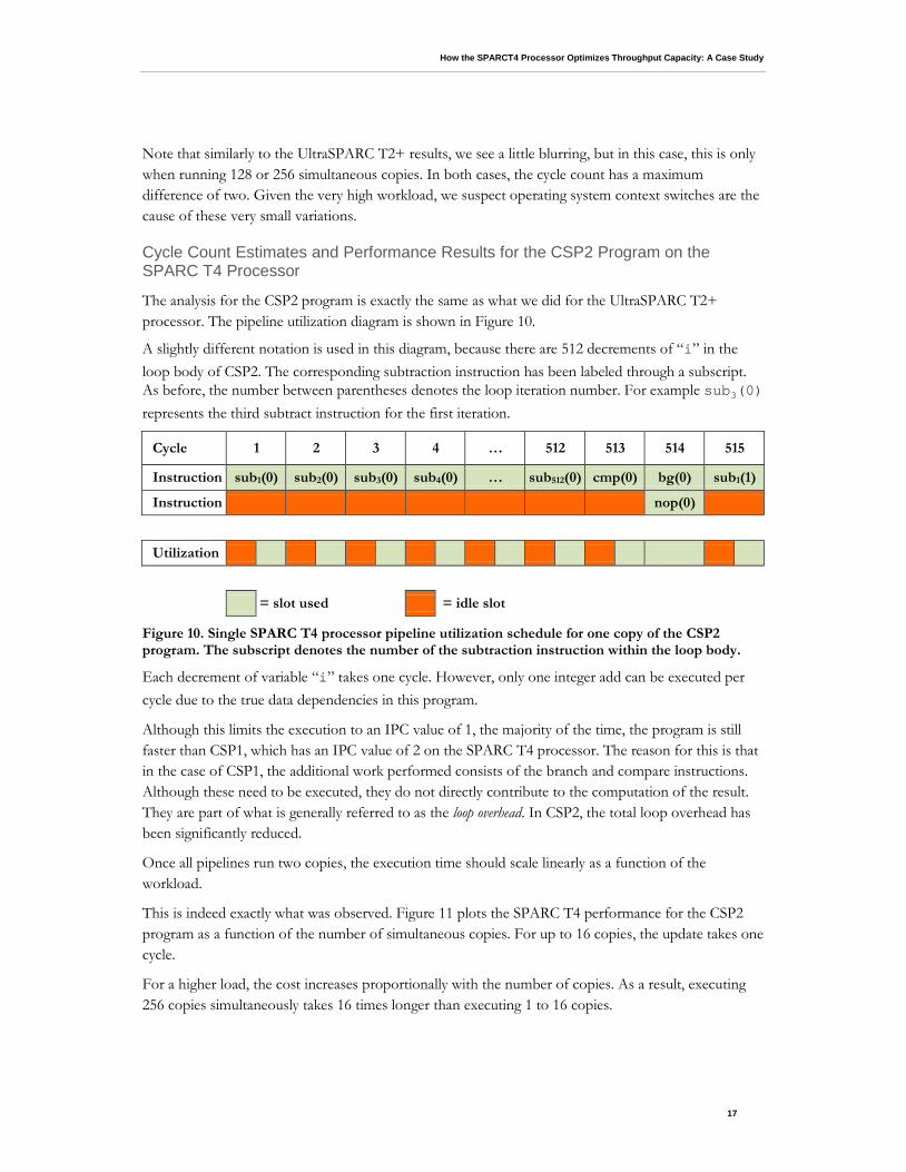
The analysis for the CSP2 program is exactly the same as what we did for the UltraSPARC T2+ processor. The pipeline utilization diagram is shown in Figure 10.
A slightly different notation is used in this diagram, because there are 512 decrements of “i” in the loop body of CSP2. The corresponding subtraction instruction has been labeled through a subscript. As before, the number between parentheses denotes the loop iteration number. For example sub3(0) represents the third subtract instruction for the first iteration.
Figure 10. Single SPARC T4 processor pipeline utilization schedule for one copy of the CSP2 program. The subscript denotes the number of the subtraction instruction within the loop body.
Each decrement of variable “i” takes one cycle. However, only one integer add can be executed per cycle due to the true data dependencies in this program.
Although this limits the execution to an IPC value of 1, the majority of the time, the program is still faster than CSP1, which has an IPC value of 2 on the SPARC T4 processor. The reason for this is that in the case of CSP1, the additional work performed consists of the branch and compare instructions. Although these need to be executed, they do not directly contribute to the computation of the result. They are part of what is generally referred to as the loop overhead. In CSP2, the total loop overhead has been significantly reduced.
Once all pipelines run two copies, the execution time should scale linearly as a function of the workload.
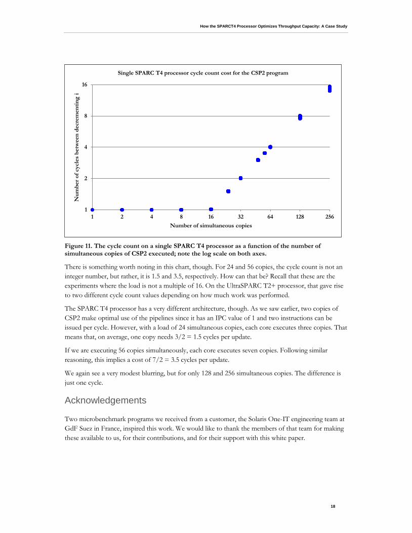
This is indeed exactly what was observed. Figure 11 plots the SPARC T4 performance for the CSP2 program as a function of the number of simultaneous copies. For up to 16 copies, the update takes one cycle.
For a higher load, the cost increases proportionally with the number of copies. As a result, executing 256 copies simultaneously takes 16 times longer than executing 1 to 16 copies.
Cycle 1 2 3 4 … 512 513 514 515
Instruction sub1(0) sub2(0) sub3(0) sub4(0) … sub512(0) cmp(0) bg(0) sub1(1)
Instruction nop(0)
Utilization
= slot used = idle slot
How the SPARCT4 Processor Optimizes Throughput Capacity: A Case Study
18
Figure 11. The cycle count on a single SPARC T4 processor as a function of the number of simultaneous copies of CSP2 executed; note the log scale on both axes.
There is something worth noting in this chart, though. For 24 and 56 copies, the cycle count is not an integer number, but rather, it is 1.5 and 3.5, respectively. How can that be? Recall that these are the experiments where the load is not a multiple of 16. On the UltraSPARC T2+ processor, that gave rise to two different cycle count values depending on how much work was performed.
The SPARC T4 processor has a very different architecture, though. As we saw earlier, two copies of CSP2 make optimal use of the pipelines since it has an IPC value of 1 and two instructions can be issued per cycle. However, with a load of 24 simultaneous copies, each core executes three copies. That means that, on average, one copy needs 3/2 = 1.5 cycles per update.
If we are executing 56 copies simultaneously, each core executes seven copies. Following similar reasoning, this implies a cost of 7/2 = 3.5 cycles per update.
We again see a very modest blurring, but for only 128 and 256 simultaneous copies. The difference is just one cycle.
Acknowledgements
Two microbenchmark programs we received from a customer, the Solaris One-IT engineering team at GdF Suez in France, inspired this work. We would like to thank the members of that team for making these available to us, for their contributions, and for their support with this white paper.
1
2
4
8
16
1 2 4 8 16 32 64 128 256
Num
ber o
f cyc
les
betw
een
decr
emen
ting
i
Number of simultaneous copies
Single SPARC T4 processor cycle count cost for the CSP2 program
How the SPARCT4 Processor Optimizes Throughput Capacity: A Case Study
19
References
[1] “OpenSPARC T2 Core Microarchitecture Specification”, December 2007: http://www.opensparc.net/pubs/t2/docs//OpenSPARCT2_Core_Micro_Arch.pdf
[2] OpenSPARC Internals—OpenSPARC T1/T2 Chip Multithreaded Throughput Computing, David L. Weaver (editor), October 2008: http://www.opensparc.net/publications/books/opensparc-internals.html
[3] Oracle Solaris Studio home page: http://www.oracle.com/us/products/servers-storage/solaris/studio/overview
[4] “Oracle’s SPARC T4-1, SPARC T4-2, SPARC T4-4, and SPARC T4-1B Server Architecture,” October 2011: http://www.oracle.com/technetwork/server-storage/sun-sparc-enterprise/documentation/o11-090-sparc-t4-arch-496245.pdf
About the Authors
Ruud van der Pas joined Oracle (then, Sun) in September 1998. He has a degree in mathematics and physics and works as a Senior Staff Engineer in the Architecture and Performance group within the SPARC organization at Oracle. His area of expertise is application performance, both for single-threaded applications as well as for (shared memory) parallel programs. Ruud’s blog can be found at http://blogs.oracle.com/ruud.
Jared Smolens is a Principal Engineer at Oracle in Santa Clara, CA where he leads performance and power modeling of a future SPARC processor core. He received his Ph.D. degree in Computer Engineering from Carnegie Mellon University in 2007 and has authored several papers on soft error detection.
How the SPARC T4 Processor Optimizes Throughput Capacity: A Case Study April 2012, Version 1.0 Authors: Ruud van der Pas and Jared Smolens
Oracle Corporation World Headquarters 500 Oracle Parkway Redwood Shores, CA 94065 U.S.A.
Worldwide Inquiries: Phone: +1.650.506.7000 Fax: +1.650.506.7200
oracle.com
Copyright © 2012, Oracle and/or its affiliates. All rights reserved. This document is provided for information purposes only and the contents hereof are subject to change without notice. This document is not warranted to be error-free, nor subject to any other warranties or conditions, whether expressed orally or implied in law, including implied warranties and conditions of merchantability or fitness for a particular purpose. We specifically disclaim any liability with respect to this document and no contractual obligations are formed either directly or indirectly by this document. This document may not be reproduced or transmitted in any form or by any means, electronic or mechanical, for any purpose, without our prior written permission.
Oracle and Java are registered trademarks of Oracle and/or its affiliates. Other names may be trademarks of their respective owners.
Intel and Intel Xeon are trademarks or registered trademarks of Intel Corporation. All SPARC trademarks are used under license and are trademarks or registered trademarks of SPARC International, Inc. AMD, Opteron, the AMD logo, and the AMD Opteron logo are trademarks or registered trademarks of Advanced Micro Devices. UNIX is a registered trademark licensed through X/Open Company, Ltd. 0611