house additions - rural municipality of taché
TRANSCRIPT

HOUSE ADDITIONSA guide to the plans required
when applying for a Building Permit

Con
tent
s
Every effort has been made to ensure the accuracy of information contained in this publication. However, in the event of a discrepancy between this
publication and the R.M of Tache Building By-law, the By-law and current Manitoba Building Code and Amendments will take precedence.
Introduction ...................................................................... 3Site Plan ........................................................................... 4Floor Plan ......................................................................... 6Foundation Plan .............................................................. 7Floor Framing Plan ........................................................ 12Section Drawing ............................................................ 13Elevation Drawing ......................................................... 15Material Specifications.................................................. 16
2
Note:The R.M of Tache Building By-law is primarily an administrative document that adopts the Manitoba Building Code and related standards to provide constructive requirements. Throughout this booklet the Manitoba Building Code will be referred to as the building code.House additions vary in size and area and it is beyond the scope of this booklet to deal with every possible situation. The requirements and construction guidelines that follow are provided to assist you in designing and constructing a house addition which will comply with the regulations. If the nature of your project is different than that contained in this booklet and you are not familiar with the regulations which may be applicable, it is recommended that you contact the R.M of Tache building inspector.

This booklet is a guide to the type of plans that are required by the R.M of Tache when applying for a building permit to construct a “basic” addition to your house. This booklet does not cover all code requirements. Reference should be made to the R.M of Tache Building By-law and the Manitoba Building Codefor the complete set of code requirements.
Permit RequirementsTwo sets of plans (one digital and one paper) are required for permit applications. Plan sets should be scaled and must include at least:
• Surveyor’sBuildingLocationCertificateifavailable,or,alternatively,awell-drawnsiteplanmaysuffice
• Building elevations• Floor plan(s)• Foundation plan• Floor framing plan• Section drawing from foundation through roof
Professional Engineering RequirementsA professional engineer will be required to seal the plans when:
a) there are any variations from the minimum standardscontained within the building code, and/or
b) the construction involves the use of structuralcomponents such as steel or engineered wood beams,‘I’-joistfloorsystems,suspendedwoodfloors,tallwallsthat exceed 11’-10” in height, pre-cast concrete, steelbrackets, pile foundations, etc., or
c) where the designated authority having juristictiondeems the nature of the work to be overly complex.
Electrical and/or Plumbing RequirementsSeparate permits are required for all plumbing work to be competed. For electrical permits please contact Manitoba Hydro. Permits for plumbing work may be applied for by:
a) the owner of a detached single family dwelling who willalso be the occupant and who will be performing theirown work, or
b) a plumbing contractor with a valid journeyman licenseissued by the Province of Manitoba.
Introduction
3

Sit
e P
aln These permits must be obtained prior to starting any of the work.
More information about this work can be found in the “Plumbing Installations” brochures available on-line at www.rmtache.ca
Site Plan RequirementsThe site plan should have the following information (see FIGURE 1):
a) street names, lot dimensions, civic address, legaldescription, and north arrow;
b) dimensions from building to property lines (building tobuilding if applicable);
c) on irregular shaped lots, dimensions from property linesto the closest projections within side yards must beincluded;
d) dimensions of all projections such as, alcoves, canopies,eaves,
e) decks,fireplaces,landings,steps,wingwalls,etc.;f) locations of downspouts and sump pump discharge
(sump pump discharge outlet will not be permitted on theside of the foundation adjacent to a public sidewalk);
g) the dimensions and locations of existing and proposedaccessory structures (examples are detached garages,sheds, air-conditioning units);
h) the dimension, location and type of surface of existingand proposed approaches, driveways and vehicleparking areas;
i) construction accesses other than lane;j) location and dimensions of registered easements
(eg. swales, land drainage sewer/catch basin lead);k) paper size should be 8 1/2 x 11 in. or 8 1/2 x 14 in.
Note: The site plan and construction drawings must match.
4

FIGURE 1 - Typical Site PlanS
ite Plan
5

Floo
r P
lan Floor Plan Requirements
This plan must have the following details (see FIGURE 2):a) size of addition, dimensioned;b) size and type of rooms in addition;c) location and sizes of windows, doors, closets, etc.
Note: windows are not permitted in walls that are locatedless than 1.2 m (4 ft) from the property line when facingneighbouring property.
d) ifthereisafireplace/woodstove,indicatetypeandlocation;
e) size of beam/lintel in wall openings, if required;f) wired-in smoke/CO alarm (SA) location - at least one is
required if the addition includes a new bedroom.(One in the bedroom and one in a location betweenbedroom and remainder of the building)
*Note: Each bedroom must have at least one outside windowwhich provides an unobstructed opening of not less than0.35 sq.m. (3.77 sq. ft.) in area and no dimension less than380 mm (15 in.).
FIGURE 2 - Typical Floor Plan
6

Foundation Plan RequirementsTypical house addition foundation plans and details are shown in FIGURES 3 to 7.
The two basic types of foundations you can use when constructing an addition are a full basement and a pile/pier and footing foundation.
1. Full Basement Foundationa) If you construct a wood basement it must be designed
and sealed by a registered professional engineer, andthe engineer must be retained to inspect and certify theinstallation.
b) If you construct a concrete basement it must meetthe minimum code standards for wall thickness andreinforcementasshowninthefollowingfigures.
FIGURE 3 - Typical Full Basement Foundation Plan
Foundation Plan
7

FIGURE 4 - Laterally Supported Foundation WallsFo
unda
tion
Pla
n
8

Foundation Plan
FIGURE 5 - Laterally Unsupported Foundation Walls
NOTES: (For FIGURES 4 and 5)
1. Length of supported joists shall not exceed 4.9 m (16 ft.).2. Top of foundation shall be at least 150 mm (6 in.) above
finishedgroundlevel.3. Walls over 12 m (40 ft.) in length shall be designed by a
registered professional engineer.4. Maximum window opening size is 1.2 m (4 ft.) and
openings not to exceed 25% of the wall length.
Interior Footing SizesOne-Storey750 mm x 750 mm x 250 mm deep @ 3.05 m o.c.(30 in. x 30 in. x 10 in. deep @ 10 ft. o.c.)
Two-Storey900 mm x 900 mm x 300 mm deep @ 2.74 m o.c.(36 in. x 36 in. x 12 in. deep @ 9 ft. o.c.)
9

Pile/Pier and Footing Foundationa) If you construct a one (1) storey addition, your
foundation must meet the minimum standards as shown;or it must be designed and sealed by a professionalengineer.
b) If you construct a two (2) storey addition, a grade beamand pile foundation must be designed and sealed by aprofessional engineer.
c) A wood beam can be used instead of a concrete gradebeam. Pile spacing and size would still be the same asillustrated below.
FIGURE 6 - Typical Pile and Grade Beam Foundation Plan
Foun
dati
on P
lan
10
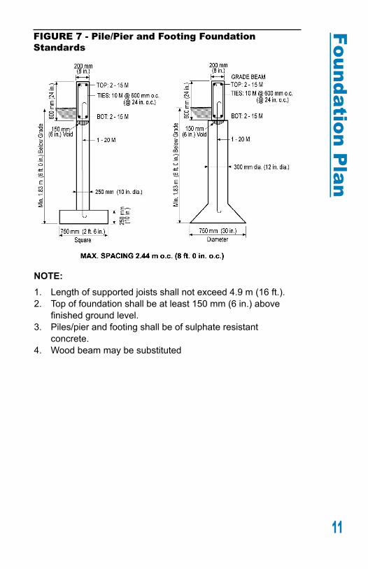
FIGURE 7 - Pile/Pier and Footing Foundation Standards
NOTE:1. Length of supported joists shall not exceed 4.9 m (16 ft.).2. Top of foundation shall be at least 150 mm (6 in.) above
finishedgroundlevel.3. Piles/pier and footing shall be of sulphate resistant
concrete.4. Wood beam may be substituted
2
34
Foundation Plan
11

Floor Framing Plan RequirementsThe details required on this plan are as follows (see FIGURE 8):
a) size of addition, dimensioned;b) joist size, grade, spacing and direction;c) bridging and strapping location, blocking;d) location of openings and member sizes;e) beam sizes if not shown on foundation plan;f) pre-manufacturedI-joistsrequiresubmissionoffinal
I-joist layout(s)g) complete with engineering.
FIGURE 8 - Typical Floor Framing Plan
Floo
r Fr
amin
g P
lan
12

Section Drawing RequirementsThe following details should be indicated on the section drawing (see FIGURE 9):
a) Type and thickness of materials in the roof, walls andfloorconstructionassembly;(seeappropriatetablesformaterial selection)
b) If roof is to be a truss system it shall be prefabricated anddesigned by a Professional Engineer.
FIGURE 9 - Section Drawing
Section D
rawing
13

Insulation RequirementsInsulation values are determined based on whether or not an HRV is being installed (see FIGURE 10).
FIGURE 10 – Insulation Requirements
Minimum Effective Thermal Resistance (RSI-Value)
Building Assembly HRV No HRV
Above Ground
Ceilings below attics 48.3 59.2Vaultedceilings&flatroofs 28.5 28.5Walls 15.9 17.5Floors over unheated spaces 28.5 28.5
Below Ground
Foundation walls 15.9 19.6Unheatedfloorsbelowfrostline - -Unheatedfloorsabovefrostline 11.1 11.1Slabs-on-grade with an integral footing 16.1 21.1
NOTE: The values in the above table are cumulative for the entire assembly. Example – a wall assembly that includes 2 X 6 wood studs at 16” on center, R22 batt insulation, 1/2” drywall interiorfinish,7/16OSBexteriorsheathingand5/8”thickstuccohas an effective R-Value of 16.5.
Heat Recovery Ventilator (HRV) RequirementsAn HRV is required on a house addition permit when:
• a secondary suite is being created.• the renovation and/or addition affects 50% or more
ofthefinaltotalexteriorwallarea.• the authority having jurisdiction deems it to be
necessary.
Sec
tion
Daw
ing
14

Building Elevation RequirementsThe information to be indicated on the elevation drawing is as follows (see FIGURE 11):a) typeoffinishsidingmaterial;b) chimney height, if any;c) window and door location;d) indicate roof slope and overhang (OH);e) guardrail height/picket spacing for any landings.
FIGURE 11 - Elevations
Elevation D
rawing
15
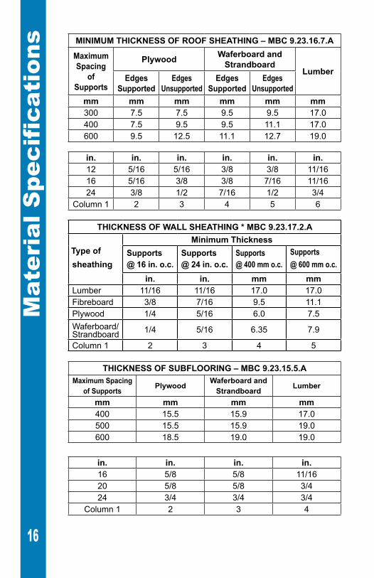
MINIMUM THICKNESS OF ROOF SHEATHING – MBC 9.23.16.7.A
Maximum Spacing
of Supports
Plywood Waferboard and Strandboard
LumberEdges
SupportedEdges
UnsupportedEdges
SupportedEdges
Unsupportedmm mm mm mm mm mm300 7.5 7.5 9.5 9.5 17.0400 7.5 9.5 9.5 11.1 17.0600 9.5 12.5 11.1 12.7 19.0
in. in. in. in. in. in.12 5/16 5/16 3/8 3/8 11/1616 5/16 3/8 3/8 7/16 11/1624 3/8 1/2 7/16 1/2 3/4
Column 1 2 3 4 5 6
THICKNESS OF WALL SHEATHING * MBC 9.23.17.2.A
Type of sheathing
Minimum ThicknessSupports@ 16 in. o.c.
Supports@ 24 in. o.c.
Supports@ 400 mm o.c.
Supports@ 600 mm o.c.
in. in. mm mmLumber 11/16 11/16 17.0 17.0Fibreboard 3/8 7/16 9.5 11.1Plywood 1/4 5/16 6.0 7.5Waferboard/Strandboard 1/4 5/16 6.35 7.9
Column 1 2 3 4 5
THICKNESS OF SUBFLOORING – MBC 9.23.15.5.AMaximum Spacing
of Supports Plywood Waferboard and Strandboard Lumber
mm mm mm mm400 15.5 15.9 17.0500 15.5 15.9 19.0600 18.5 19.0 19.0
in. in. in. in.16 5/8 5/8 11/1620 5/8 5/8 3/424 3/4 3/4 3/4
Column 1 2 3 4
Mat
eria
l Spe
cifi
cati
ons
16
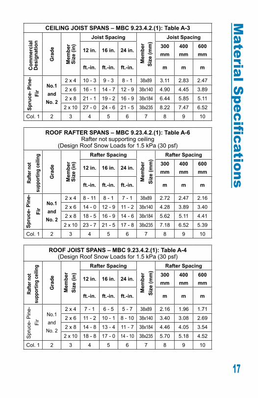
CEILING JOIST SPANS – MBC 9.23.4.2.(1): Table A-3C
omm
erci
al
Des
igna
tion
Gra
de
Mem
ber
Size
(in)
Joist Spacing
Mem
ber
Size
(mm
)
Joist Spacing
12 in. 16 in. 24 in.300 mm
400 mm
600 mm
ft.-in. ft.-in. ft.-in. m m m
Spru
ce- P
ine-
Fi
r
No.1and
No. 2
2 x 4 10 - 3 9 - 3 8 - 1 38x89 3.11 2.83 2.47
2 x 6 16 - 1 14 - 7 12 - 9 38x140 4.90 4.45 3.89
2 x 8 21 - 1 19 - 2 16 - 9 38x184 6.44 5.85 5.11
2 x 10 27 - 0 24 - 6 21 - 5 38x235 8.22 7.47 6.52
Col. 1 2 3 4 5 6 7 8 9 10
ROOF RAFTER SPANS – MBC 9.23.4.2.(1): Table A-6Rafter not supporting ceiling
(Design Roof Snow Loads for 1.5 kPa (30 psf)
Rafte
r not
su
ppor
ting
ceili
ng
Gra
de
Mem
ber
Size
(in)
Rafter Spacing
Mem
ber
Size
(mm
)Rafter Spacing
12 in. 16 in. 24 in.300 mm
400 mm
600 mm
ft.-in. ft.-in. ft.-in. m m m
Spru
ce- P
ine-
Fir
No.1and
No. 2
2 x 4 8 - 11 8 - 1 7 - 1 38x89 2.72 2.47 2.16
2 x 6 14 - 0 12 - 9 11 - 2 38x140 4.28 3.89 3.40
2 x 8 18 - 5 16 - 9 14 - 6 38x184 5.62 5.11 4.41
2 x 10 23 - 7 21 - 5 17 - 8 38x235 7.18 6.52 5.39
Col. 1 2 3 4 5 6 7 8 9 10
ROOF JOIST SPANS – MBC 9.23.4.2.(1): Table A-4(Design Roof Snow Loads for 1.5 kPa (30 psf)
Rafte
r not
su
ppor
ting
ceili
ng
Gra
de
Mem
ber
Size
(in)
Rafter Spacing
Mem
ber
Size
(mm
)
Rafter Spacing
12 in. 16 in. 24 in.300 mm
400 mm
600 mm
ft.-in. ft.-in. ft.-in. m m m
Spr
uce-
Pin
e-
Fir
No.1and
No. 2
2 x 4 7 - 1 6 - 5 5 - 7 38x89 2.16 1.96 1.71
2 x 6 11 - 2 10 - 1 8 - 10 38x140 3.40 3.08 2.69
2 x 8 14 - 8 13 - 4 11 - 7 38x184 4.46 4.05 3.54
2 x 10 18 - 8 17 - 0 14 - 10 38x235 5.70 5.18 4.52
Col. 1 2 3 4 5 6 7 8 9 10
Material S
pecifications
17

Mat
eria
l Spe
cifi
cati
ons NOTE: The tables contained in this brochure are only a guide
and do not cover all structural limitations available in the code. A Professional Engineer may be required for any variations from the minimum standards contained within these tables and in the Manitoba Building Code.
BUILT-UP FLOOR BEAM SPANS – MBC 9.23.4.2.(3): Table A-8 Supporting ONE Floor in Houses
Spruce-Pine-Fir Grade No. 1 & 2
Size
of
Bea
m
Supported Joist Length
Size
of
Bea
m
Supported Joist Length8 ft. 10 ft. 12 ft. 14 ft. 16 ft. 2.4 m 3.0 m 3.6 m 4.2 m 4.8 m
ft.-in. ft.-in. ft.-in. ft.-in. ft.-in. m m m m m3-2x 8 10 - 7 9 - 5 8 - 8 8 - 0 7 - 6 3-38x184 3.25 2.90 2.65 2.45 2.30
4-2x 8 12 - 2 10 - 11 10 - 0 9 - 3 8 - 8 4-38x184 3.75 3.35 3.06 2.83 2.65
3-2x10 12 - 11 11 - 7 10 - 7 9 - 9 9 - 2 3-38x235 3.97 3.55 3.24 3.00 2.81
4-2x10 14 - 11 13 - 4 12 - 2 11 - 3 10 - 7 4-38x235 4.59 4.10 3.74 3.47 3.24
3-2x12 15 - 0 13 - 5 12 - 3 11 - 4 10 - 7 3-38x286 4.61 4.12 3.76 3.48 3.26
4-2x12 17 - 4 15 - 6 14 - 2 13 - 1 12 - 3 4-38x286 5.32 4.76 4.34 4.02 3.76
1 2 3 4 5 6 7 8 9 10 11 12
BUILT-UP FLOOR BEAM SPANS – MBC 9.23.4.2.(3): Table A-8 Supporting TWO Floors in HousesSpruce-Pine-Fir Grade No. 1 & 2
Size
of
Bea
m
Supported Joist Length
Size
of
Bea
m
Supported Joist Length8 ft. 10 ft. 12 ft. 14 ft. 16 ft. 2.4 m 3.0 m 3.6 m 4.2 m 4.8 m
ft.-in. ft.-in. ft.-in. ft.-in. ft.-in. m m m m m3-2x 8 8 - 0 7 - 2 6 - 7 6 - 1 5 - 8 3-38x184 2.46 2.20 2.01 1.86 1.74
4-2x 8 9 - 3 8 - 3 7 - 7 7 - 0 6 - 7 4-38x184 2.85 2.55 2.32 2.15 2.01
3-2x10 9 - 10 8 - 9 8 - 0 7 - 5 6 - 10 3-38x235 3.01 2.70 2.46 2.28 2.11
4-2x10 11 - 4 10 - 2 9 - 3 8 - 7 8 - 0 4-38x235 3.48 3.11 2.84 2.63 2.46
3-2x12 11 - 5 10 - 2 9 - 4 8 - 7 7 - 9 3-38x286 3.50 3.13 2.85 2.64 2.38
4-2x12 13 - 2 11 - 9 10 - 9 9 - 11 9 - 4 4-38x286 4.04 3.61 3.30 3.05 2.85
1 2 3 4 5 6 7 8 9 10 11 12
18

FLOOR JOIST SPANS – 9.23.4.2.(1): Table A-1C
omm
erci
al
Des
igna
tion
Gra
de
Mem
ber
Size
(in)
Joist Spacing with Strapping
Joist Spacing with Bridging
Joist Spacing with Strapping
& Bridging12 in. 16 in. 24 in. 12 in. 16 in. 24 in. 12 in. 16 in. 24 in.
ft.-in. ft.-in. ft.-in. ft.-in. ft.-in. ft.-in. ft.-in. ft.-in. ft.-in.
Spru
ce- P
ine-
Fir
No.1
and
No. 2
(in.)12 in. 16 in. 24 in. 12 in. 16 in. 24 in. 12 in. 16 in. 24 in.ft.-in. ft.-in. ft.-in. ft.-in. ft.-in. ft.-in. ft.-in. ft.-in. ft.-in.
2 x 4 6 - 1 5 - 8 5 - 2 6 - 6 5 - 11 5 - 2 6 - 6 5 - 11 5 - 2
2 x 6 9 - 7 8 - 11 8 - 2 10 - 4 9 - 4 8 - 2 10 - 4 9 - 4 8 - 2
2 x 8 11 - 7 11 - 0 10 - 6 12 - 5 11 - 9 10 - 9 13 - 1 12 - 2 10 - 9
2 x 10
13 - 8 13 - 0 12 - 4 14 - 6 13 - 812 - 10
15 - 1 14 - 1 13 - 2
2 x 12
15 - 714 - 10
14 - 1 16 - 4 15 - 5 14 - 6 17 - 015 - 10
14 - 9
(mm)300mm 400mm 600mm 300mm 400mm 600mm 300mm 400mm 600mm
m m m m m m m m m
38x89 1.86 1.72 1.58 1.99 1.81 1.58 1.99 1.81 1.58
38x140 2.92 2.71 2.49 3.14 2.85 2.49 3.14 2.85 2.49
38x184 3.54 3.36 3.20 3.79 3.57 3.27 3.99 3.72 3.27
38x235 4.17 3.96 3.77 4.41 4.16 3.92 4.61 4.30 4.01
38x286 4.75 4.52 4.30 4.99 4.70 4.42 5.17 4.82 4.50
Col. 1 2 3 4 5 6 7 8 9 10 11 12
Park
Broadway
19