hot gas stand durability tests for turbine housing design … · performance testing on renault...
TRANSCRIPT

© 2015 MITSUBISHI TURBOCHARGER AND ENGINE EUROPE BV All Rights Reserved.
Hot Gas Stand durability tests for
Turbine Housing design validation
SyTec M2A 2015
A. Loret - Turbo Engineering
13th October 2015

1
1. Scope
2. Hot Gas Stand test set-up
3. Endurance test cycles
4. Validation results
5. Summary

2
Context of the study
New Turbine Housing concept was implemented on turbocharger prototypes for
performance testing on Renault Diesel engine.
In partnership with Renault S.A.S, pre-development activities were defined to
validate the main risks identified with this new technology.
Durability validation activities were performed by MTEE on Hot Gas Stand test
benches.
Most of these Hot Gas Stand durability tests were conducted using CRITT test
facilities and CRITT engineering support.
Scope

3
Targets of the Hot Gas Stand durability tests
Purpose of the HGS endurance tests is to evaluate the Turbine Housing design
durability under thermo-mechanical stress levels representative of actual engine
operating conditions.
Main objectives are:
- Assess the Turbine Housing durability level for implementation on industrial
project
- Validate the Turbine Housing design to secure performance testing on engine
with prototypes parts
Scope

4
Thermal shock endurance test in MHI
First evaluation of the Turbine Housing new design is performed on MHI
Hot Gas Stand on the turbocharger only.
Hot Gas Stand test set-up

5
Thermal shock endurance test in CRITT
A durability test on the complete engine exhaust face is performed on CRITT Hot
Gas Stand.
For this purpose, specific adaptation parts are designed and manufactured
by CRITT :
- A hot gas distribution unit in austenetic stainless steel, which function is to
split the gas flow coming from the burner and divide it in 4 equal gas streams.
- An aluminium plate with watercooling connection.
It is fixed on distribution unit with a seal to guaranty that no leak occurs.
- A mobile support rack which function is to support the distribution unit and
provide fixation points for bracketing of the engine exhaust face components.
Hot Gas Stand test set-up

6
Hot Gas Stand test set-up
Distribution unit
Burner
Aluminium plate
with watercooling
Tested system:
engine exhaust face
Mobile support racks
3D model of the test installation at CRITT

7
Hot Gas Stand test set-up
3D model of the test installation at CRITT

8
Hot Gas Stand test set-up
Picture of the test installation at CRITT

9
Endurance MHI : thermal shock cycle
Endurance test cycles
Duration time 200 hours
1 cycle 550 sec
(Hot 160 sec / Cold 390 sec)
Turbine inlet
Temperature Hot 850 degC / Cold 100 degC
Test conditions
Turbine inlet temperature measurement results in cycle

10
1st Endurance CRITT : thermal shock cycle
Endurance test cycles
Duration time 200 hours
1 cycle 530 sec
(Hot 130 sec / Cold 400 sec)
Turbine inlet
Temperature Hot 800 degC / Cold 110 degC
Test conditions
Turbine inlet temperature measurement results in cycle
11
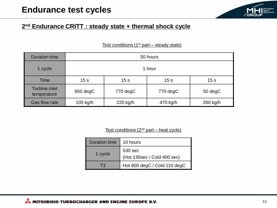
Endurance test cycles
Duration time 10 hours
1 cycle 530 sec
(Hot 130sec / Cold 400 sec)
T3 Hot 800 degC / Cold 110 degC
Duration time 50 hours
1 cycle 1 hour
Time 15 s 15 s 15 s 15 s
Turbine inlet
temperature 650 degC 770 degC 770 degC 50 degC
Gas flow rate 105 kg/h 220 kg/h 470 kg/h 260 kg/h
Test conditions (1st part – steady state)
Test conditions (2nd part – heat cycle)
2nd Endurance CRITT : steady state + thermal shock cycle

12
Validation test results
cracks
Endurance MHI : Investigation results after 200hrs of thermal shock cycle
cracks
13
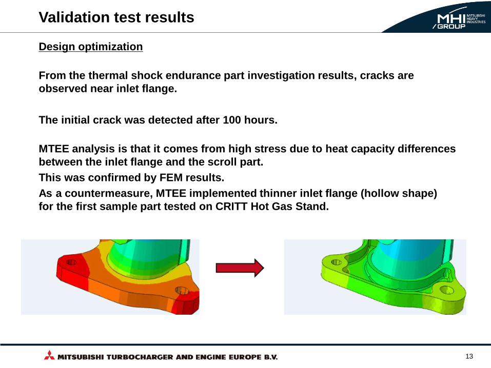
Design optimization
From the thermal shock endurance part investigation results, cracks are
observed near inlet flange.
The initial crack was detected after 100 hours.
MTEE analysis is that it comes from high stress due to heat capacity differences
between the inlet flange and the scroll part.
This was confirmed by FEM results.
As a countermeasure, MTEE implemented thinner inlet flange (hollow shape)
for the first sample part tested on CRITT Hot Gas Stand.
Validation test results
cracks
(a) (b)

14
Thermal characterization on CRITT Hot Gas Stand
Validation test results
Time Engine reference data CRITT thermal shock cycle data
Skin temperature
of monitoring point Duration
Skin temperature
of monitoring point Duration
Hot phase
(T3=800degC) 670 degC 115 sec 668 degC 130 sec
Cold phase 100 degC 410 sec 110 degC 400 sec
Monitoring point
Test results comparison on exhaust manifold

15
Thermal characterization on CRITT Hot Gas Stand
Validation test results
Test results comparison on reference Turbocharger

16
Validation test results
0.00
0.50
1.00
1.50
2.00
2.50
3.00
3.50
4.00
4.50
0°
45°
90°
135°
180°
225°
270°
315°
200hrs thermal shock CRITT
200hrs thermal shock MHI
Shroud area Support Plate
Deformation level between Support plate and Shroud area
1st Endurance CRITT : Plastic deformation comparison

17
Validation test results
Design optimization
From the thermal shock endurance part investigation results, severe plastic
deformation is observed on Turbine Housing.
No cracks were detected at the end of the CRITT endurance test.
As a countermeasure, MTEE implemented reinforcements between turbine
outlet flange and support plate in order to increase the structural stiffness of the
Turbine Housing.
This modification was implemented on a second sample part tested on CRITT
Hot Gas Stand.

18
Validation test results
-0.4
-0.3
-0.2
-0.1
0
0.1
0.2
0.3
0.4
0.5
0.6
0.7
0°
45°
90°
135°
180°
225°
270°
315°
40hrs engine performance test
10hrs engine performance test
50hrs + 10hrs CRITT endurance
Shroud area Support Plate
Deformation level between Support plate and Shroud area
2nd Endurance CRITT : Plastic deformation comparison

19
Endurance test campaign performed on Hot Gas Stand benches allowed to
achieve below targets:
- Assess the Turbine Housing durability level for implementation on industrial
project.
Further design optimization steps are required to achieve the durability target
requirements with a design suitable for mass production.
- Validate the Turbine Housing design to secure performance testing on engine
with prototypes parts.
2 design optimization loops were implemented based on the thermal shock
endurance tests results.
The sample with optimized design could meet the durability targets defined for
performance testing on engine.
All engine performance test have been performed successfully with this
optimized Turbine Housing design.
Summary

20 © 2015 MITSUBISHI TURBOCHARGER AND ENGINE EUROPE BV All Rights Reserved.