holley gm bbc single-plane efi intake manifold kits gm bbc single-plane efi intake manifold kits...
TRANSCRIPT
Holley GM BBC Single-Plane EFI Intake Manifold Kits
300-561 Oval Port, 4150 Flange
300-562 Oval Port, 4500 Flange
300-563 Rectangular Port, 4150 Flange
300-564 Rectangular Port, 4500 Flange
INSTALLATION INSTRUCTIONS 199R10717
(Before installation, please read these instructions completely.)
IMPORTANT: Although all Holley parts pass several inspections, it is imperative that the installer personally inspects the part before
installation. Run a stiff wire through passages while shining a bright light into it. Also, wash the part using a mild soap and water solution. Check the fit on all bolt holes for proper alignment and thread any fittings in first by hand. Failure to perform these simple checks could result in engine damage and may void your warranty.
APPLICATIONS:
These Holley® intake manifolds are designed for Mark IV-VI, 396-502 cid Big Block Chevrolet engines equipped with standard Oval (300-561 & 300-562) or Rectangular (300-563 & 300-564) port cylinder heads with standard deck height applications for both 4150 square bore and 4500 Dominator™ carburetor flange configurations. These manifolds will also work with any BBC equipped with aftermarket cylinder heads, as long as they have standard Oval or Rectangle port flange openings and bolt hole locations. These single-plane intake manifolds are designed for high-performance engine applications up to 540 cubic inch displacement and maximum engine speeds of 7000-8000 rpm, depending on the engine combinations. Holley® intake manifolds are intended for maximum performance applications and may not accept stock components and hardware. They may not fit under an unmodified hood for many vehicle applications.
NOTE: These intake manifolds and fuel rails are designed to accept Bosch Style EV-1 in addition to many other OE or aftermarket fuel injectors. The brackets supplied with the fuel rail kit provided are for the installation of a Bosch EV-1 style injector or a GM LS7 style fuel injector.
EMISSIONS EQUIPMENT:
Holley intake manifolds do not accept any emission-control devices. This part is not legal for sale or use for motor vehicles with pollution-controlled equipment.
ELECTRONIC FUEL INJECTION:
These intake manifolds are intended for use with electronic fuel injection. Holley EFI has a full line of engine management systems, throttle bodies, fuel injectors, and other installation components required to successfully set-up and operate an electronically fuel injected engine for applications ranging from street to heads-up competitive racing with forced induction or nitrous. Go to the Holley EFI home page within www.holley.com for a full description of EFI engine management systems, EFI components, and accessories available for your GM BBC engine and the Holley EFI intake manifolds.
DIMENSIONS:
A-B Height – A – 5.96” (front), B - 5.96” (rear). NOTE: Measured from font and rear manifold end seal surfaces.
Oval Port Size – 1.87” High x 1.60” Wide
Rectangular Port Size – 2.28” High x 1.48” Wide
INSTALLATION KIT CONTENTS:
3 – 1/2 NPT Hex Pipe Plug 1 – Installation Instructions 1 – Warranty Card
2
FUEL RAIL KIT CONTENTS:
P/N 534-223
2 – Fuel Rails, High Volume, Configured with 3/4-16 O-ring Ports (AN-8) 6 – Brackets, Long, EV1 type Fuel Injectors, Zinc Plated Black 6 – Brackets, Short, GM LS7 type Fuel Injectors, Zinc Plated Black 6 – Cap Screws, Flanged Hex-Head, 5/16-18 x .50” Long, Fuel Rail to Bracket 6 – Cap Screws, Flanged Hex-Head, 5/16-18 x .75” Long, Bracket to Intake Manifold 8 – O-rings, Fuel Injector, Outlet End (to adapt OE LS7 injector to fit into Holley intake manifold)
PARTS REQUIRED: NOTE: It will be necessary to purchase some of the parts listed below (or their equivalents) in order to properly complete the manifold
installation. Determination of equivalency is the responsibility of the consumer. Holley does not assume that responsibility.
Intake manifold gasket set (300-561/300-562 - Fel-Pro® P/N 1212 or 300-563/300-564 - Fel-Pro® P/N 1275) is recommended Valve cover gasket set Thermostat housing gasket (Fel-Pro® P/N 2201,2202) Oil-resistant, silicone-based sealant (Permatex® silicone form-a-gasket., Dow Corning® Silastic®, or equivalent) Spray gasket adhesive (Permatex® 80064 High Tack™ Spray-A-Gasket™ sealant or equivalent) Throttle body-base gasket (usually supplied with throttle body) Thread sealer (Loctite® 565, Permatex® 56521, or equivalent) NOTE: Never install tapered (pipe) fittings in an aluminum manifold dry without thread sealer or thread damage will occur.
INSTALLING YOUR INTAKE MANIFOLD: 1. Clean the cylinder head port flange and the engine block end seal surfaces. To prevent gasket pieces from falling into ports and
the lifter valley when cleaning old gaskets from head surfaces, stuff paper towels into all the ports and lay rags in the lifter valley. When clean, carefully remove the paper towels from the cylinder head ports and then the rags from the lifter valley. Make sure that all particles that fell on the rags are completely removed. Wipe surfaces with rags soaked in solvent, such as brake cleaner or lacquer thinner to remove any oils or grease. This is a must for proper manifold/gasket sealing.
2. Apply a thin coat of gasket adhesive to the cylinder head side of the intake gasket surfaces and the cylinder head port flanges.
Allow the adhesive to completely dry. Lay the manifold gaskets in place, making sure that gaskets are adhered to the cylinder head port flange and will not slip from their properly installed positions.
3. Trial fit your new intake manifold before applying any RTV silicone sealant. Place the new intake manifold into position; check that
it sits down, properly seated on the intake manifold gaskets. There should be gap between the engine block and the manifold at the end seal surfaces. Check to make sure all of the intake manifold bolts can be installed. If there are any other fit issues such as hood clearance or installation of components dependent on the manifold, they should be checked at this time.
4. When you are fully prepared to install the intake manifold, apply a 1/4” wide bead of oil-resistant RTV-silicone sealant to the front
and rear block-sealing surfaces, making sure to overlap manifold gaskets at all four corners. Do not use the cork or rubber end seal gaskets included in the gasket set. Apply a light film of RTV-silicone around the water passage openings.
5. Carefully, lay your intake manifold in place. If the manifold must be moved, the RTV-silicone may need to cleaned and re-applied.
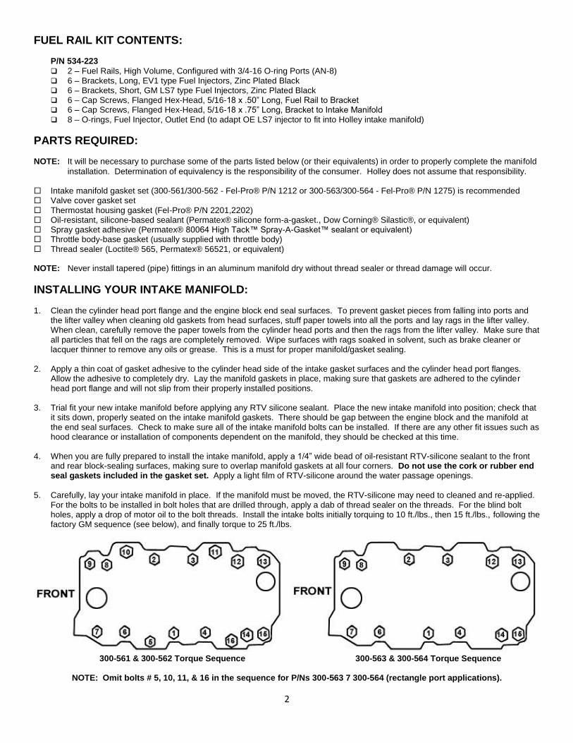
For the bolts to be installed in bolt holes that are drilled through, apply a dab of thread sealer on the threads. For the blind bolt holes, apply a drop of motor oil to the bolt threads. Install the intake bolts initially torquing to 10 ft./lbs., then 15 ft./lbs., following the factory GM sequence (see below), and finally torque to 25 ft./lbs.
300-561 & 300-562 Torque Sequence 300-563 & 300-564 Torque Sequence
NOTE: Omit bolts # 5, 10, 11, & 16 in the sequence for P/Ns 300-563 7 300-564 (rectangle port applications).
3
6. Install the thermostat, gasket, and thermostat housing. Be sure that the thermostat housing is in good condition and has been cleaned of any old gasket material. If the mounting flange on the thermostat housing is not flat or is damaged, replace it before continuing.
7. Install the heater hose fitting, coolant bypass hose fitting, bypass hose, heater hose, and radiator hoses. Use thread sealer on the
threads of the heater hose fitting. 8. Install the gauge sensors and vacuum fittings into the manifold. Use thread sealer on the pipe threads of the sensors and fittings.
Install pipe plugs in any unused water and vacuum ports in the manifold (plugs have been provided in the kit). 9. Install the distributor and gasket orienting the rotor and the distributor body according to the reference marks made before the
distributor was removed (Distributor Removal Section). Make sure that your distributor engages the oil pump drive shaft and seats properly down against the gasket and manifold. Install the distributor clamp and tighten the bolt just enough that the distributor body can still be rotated by hand.
10. Install your four throttle body studs in the manifold. Place the throttle body gasket on the clean throttle body pad. Do not use any
type of sealant on the carburetor gasket. 11. Install the throttle body. Connect all linkage and throttle springs. 12. Connect all vacuum and fuel lines. Refer to your tags or drawings for correct placement. 13. Automatic transmissions only: Adjust kick-down or throttle pressure linkage for proper shift points (refer to your vehicle’s shop
manual for the proper adjustment procedure). Check all linkages, making sure that they function freely. 14. Reinstall valve covers and new gaskets.
Installation of the Fuel Rails – The fuel rails are mounted to the intake manifold by three brackets per fuel rail. The fuel rail kit supplies brackets of two different lengths. The long brackets are for mounting the fuel rails at a height for a Bosch style EV1 type fuel injector. The short brackets are for mounting the fuel rails at a height for GM OE LS7 fuel injectors. When using an OE GM LS7 injector in the Holley intake manifold, the o-ring on the outlet (intake manifold) end of the injector needs to be changed to the o-ring supplied in the fuel rail kit.
1. Apply a silicone lubricant to the o-ring on the inlet end of fuel injectors and insert the fuel injectors into the ports in the fuel rail. To
insert the injector without tearing the o-ring, gently rock the injector in the inlet of the port while applying pressure to insert the injector.
2. With the lettering on the fuel rail oriented outward, position the injectors to properly orient the wiring plugs, apply silicone lubricant to the injector outlet o-rings, and insert all four injectors into injector bosses in the base intake manifold applying gentle downward pressure on the fuel rail.
3. Once the injectors are inserted into the intake manifold, place the appropriate brackets in position. Before installing the fasteners, apply a drop of oil to the threads of the flanged hex head cap screws. Attach the brackets to the intake manifold with the 0.75” long flanged hex head cap screws. Attach the brackets to the fuel rail with the 0.50” long flanged hex head cap screws. Hand-tighten the fasteners, making sure that the brackets are properly seated on both the intake manifold and the fuel rail. Make sure that the fuel rail and fuel injectors are properly positioned. Ensure the injectors are floating on the o-rings. Rotate the injector back and forth to confirm that there is no load on the injector bodies. The injectors should have 0.020-0.040” of end play and the o-ring seals must stay in the o-ring seal counterbores.
4. Tighten the mounting fasteners in two steps, 7 ft-lbs for the first step and 12-15 ft-lbs for the second step.
5. Once the fasteners are tightened, re-check and ensure the injectors are floating on the o-rings; rotate the injectors back and forth to confirm that there is no load on the injector bodies.
6. The fuel rail is designed to provide enough flow and volume to dampen fuel pressure oscillations and variations at the inlet of the fuel injectors. The fuel rails are machined to receive an adapter fitting for 3/4-16 (AN-8) o-ring port.
For power levels below 700-750HP, AN-6 (3/8”) plumbing to and from the fuel rails should be sufficient.
For power levels above 750HP, AN-8 (1/2”) plumbing is recommended.
It is always recommended to only use tubular hose ends when a non-straight hose end is required.
4
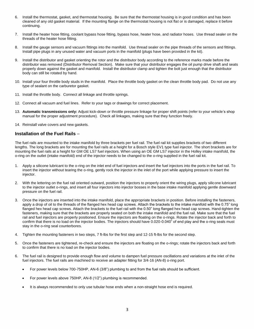
Plumbing Diagram
INSTALLING YOUR INTAKE MANIFOLD CONT’D: 1. Close the drain and fill the radiator to the proper level with coolant. While filling, allow trapped air to bleed from the intake manifold
at the heater hose fitting until coolant flows from the fitting. Then, re-install the heater hose and continue adding coolant to the proper level.
2. IMPORTANT! Change the oil to remove any coolant or debris that may have contaminated the crank case.
3. Retighten the gas cap and connect the battery cable. 4. Hook up the timing light and start the engine. Set the timing to proper specs. Tighten the distributor. 5. Check for possible fuel, oil, or coolant leaks and for proper throttle body linkage operation. 6. Install the air cleaner. CAUTION! With the air cleaner installed, check to be sure that there is adequate clearance for the throttle and choke linkages
through their full range of travel.
IMPORTANT: Check for adequate hood clearance before closing the hood.
7. Operate the engine for 30 minutes. Allow the engine to cool and re-torque the manifold bolts following step 5 above. 8. YOUR MANIFOLD INSTALLATION IS COMPLETE.
Throttle Body Recommendations: Throttle Body Recommendations:
300-561 & 300-563 – Holley P/N 112-577, 1000 cfm 4150 flange throttle body
300-562 & 300-564 – Holley P/N 112-578, 2000 cfm 4500 flange throttle body
Service Parts:
534-223 – Fuel Rail Kit, BBC Single-Plane intake manifold
534-104 – Fuel Injector O-Rings, Set of 16, O-ring supplied in fuel rail kit 534-223 to adapt LS7 injectors
Holley Technical Support 1801 Russellville Road
Bowling Green, KY 42101 270-781-9741
www.holley.com
© 2014 Holley Performance Products, Inc. All rights reserved. 199R10717 Date: 8-4-14