brocade 300 hardware installation guide...port side of the brocade 300 the port side of the brocade...
TRANSCRIPT

HARDWARE INSTALLATION GUIDE
Brocade 300 Hardware Installation Guide
53-1000862-1229 December 2017

Copyright © 2017 Brocade Communications Systems LLC. All Rights Reserved.
Brocade and the stylized B logo are among the trademarks of Brocade Communications Systems LLC. Broadcom, the pulse logo, and Connectingeverything are among the trademarks of Broadcom. The term "Broadcom" refers to Broadcom Limited and/or its subsidiaries
Brocade, a Broadcom Limited Company, reserves the right to make changes without further notice to any products or data herein to improve reliability,function, or design. Information furnished by Brocade is believed to be accurate and reliable. However, Brocade does not assume any liability arising out ofthe application or use of this information, nor the application or use of any product or circuit described herein, neither does it convey any license under itspatent rights nor the rights of others.
The product described by this document may contain open source software covered by the GNU General Public License or other open source licenseagreements. To find out which open source software is included in Brocade products, view the licensing terms applicable to the open source software, andobtain a copy of the programming source code, please visit http://www.brocade.com/support/oscd.
Brocade 300 Hardware Installation Guide2 53-1000862-12

ContentsAbout This Document........................................................................................................................................................................................................ 7
Supported hardware and software...................................................................................................................................................................................................... 7What’s new in this document................................................................................................................................................................................................................ 7Document conventions............................................................................................................................................................................................................................7
Notes, cautions, and warnings.....................................................................................................................................................................................................7Text formatting conventions......................................................................................................................................................................................................... 8Command syntax conventions....................................................................................................................................................................................................8
Document feedback..................................................................................................................................................................................................................................8
Device Overview..................................................................................................................................................................................................................9Brocade 300 features..............................................................................................................................................................................................................................9Port side of the Brocade 300............................................................................................................................................................................................................10Non-port side of the Brocade 300.................................................................................................................................................................................................10Supported fabric configurations....................................................................................................................................................................................................... 11Ports on Demand license.................................................................................................................................................................................................................... 11ISL trunking groups................................................................................................................................................................................................................................11Managing the Brocade 300...............................................................................................................................................................................................................12
Preparing for Installation.................................................................................................................................................................................................13Installation precautions......................................................................................................................................................................................................................... 13
General precautions......................................................................................................................................................................................................................13Power precautions.........................................................................................................................................................................................................................13RTC battery precautions............................................................................................................................................................................................................. 14Laser precautions.......................................................................................................................................................................................................................... 14
Facility requirements..............................................................................................................................................................................................................................14Environmental considerations............................................................................................................................................................................................................15Recommendations for cable management..................................................................................................................................................................................15Items included with the Brocade 300............................................................................................................................................................................................15
Mounting the Device........................................................................................................................................................................................................17Mounting options.................................................................................................................................................................................................................................... 17Installing a standalone Brocade 300..............................................................................................................................................................................................17EIA rack installation for a Brocade 300.........................................................................................................................................................................................17
EIA rack considerations...............................................................................................................................................................................................................18Installing the 1U, 1.5U, and 2U Mid-Mount Kit for Two-Post Racks (XBR-000165, XBR-000175, and XBR-R000292)................ 18
Time and items required.............................................................................................................................................................................................................18Parts list............................................................................................................................................................................................................................................. 19Attaching the front brackets to the device........................................................................................................................................................................... 20Attaching the device to a rack...................................................................................................................................................................................................21Attaching the rear brackets to the rack..................................................................................................................................................................................21Attaching the rear brackets to the device.............................................................................................................................................................................22
Installing the 1U and 2U Fixed-Mount Rack Kit for Four-Post Racks (XBR-R000162)........................................................................................23Time and items required.............................................................................................................................................................................................................23Parts list............................................................................................................................................................................................................................................. 24Attaching the front brackets.......................................................................................................................................................................................................26Installing the device in the rack................................................................................................................................................................................................ 27Attaching the rear brackets to the front brackets.............................................................................................................................................................. 28Attaching the rear brackets to the rack posts.....................................................................................................................................................................29
Brocade 300 Hardware Installation Guide53-1000862-12 3

Slide Rack Mount Kit (XBR-R000070)........................................................................................................................................................................................ 30Safety precautions ........................................................................................................................................................................................................................31Time and items required.............................................................................................................................................................................................................31Parts list............................................................................................................................................................................................................................................. 31Installing the device.......................................................................................................................................................................................................................33
Installing the 1U and 2U Non-Port Side Fixed-Mount Rack Kit (15"-20") for Four-Post Racks (XNA-000072 and XNA-100072)......................................................................................................................................................................................................................................................47
Time and items required.............................................................................................................................................................................................................48Parts list............................................................................................................................................................................................................................................. 48Attaching the front brackets.......................................................................................................................................................................................................49Installing the device in the rack................................................................................................................................................................................................ 51Attaching the rear brackets to the front brackets.............................................................................................................................................................. 52Attaching rear brackets to the rack posts.............................................................................................................................................................................53
Initial Setup and Verification.......................................................................................................................................................................................... 55Items required for initial setup............................................................................................................................................................................................................55Providing power to the switch............................................................................................................................................................................................................55Creating a serial connection................................................................................................................................................................................................................56Setting the switch IP address.............................................................................................................................................................................................................56
Using DHCP to set the IP address.........................................................................................................................................................................................56Setting a static IP address..........................................................................................................................................................................................................56
Date and time settings.......................................................................................................................................................................................................................... 57Time zones.......................................................................................................................................................................................................................................57Local time synchronization........................................................................................................................................................................................................ 58Setting the date...............................................................................................................................................................................................................................58Setting time zones.........................................................................................................................................................................................................................58Synchronizing local time using NTP......................................................................................................................................................................................59
Monitoring the Device..................................................................................................................................................................................................... 61Powering the Brocade 300 on and off.......................................................................................................................................................................................... 61Interpreting LED activity.......................................................................................................................................................................................................................61
Brocade 300 LEDs...................................................................................................................................................................................................................... 61LED locations..................................................................................................................................................................................................................................61LED patterns....................................................................................................................................................................................................................................62
POST and boot specifications...........................................................................................................................................................................................................63POST..................................................................................................................................................................................................................................................64Boot.....................................................................................................................................................................................................................................................64
Interpreting POST results.................................................................................................................................................................................................................... 64Maintaining the Brocade 300............................................................................................................................................................................................................64
Installing an SFP............................................................................................................................................................................................................................ 65Diagnostic tests.............................................................................................................................................................................................................................. 66Field Replaceable Units (FRUs)............................................................................................................................................................................................... 67
Brocade 300 Technical Specifications........................................................................................................................................................................69System specifications............................................................................................................................................................................................................................69Fibre Channel............................................................................................................................................................................................................................................69Ethernet.......................................................................................................................................................................................................................................................69LEDs.............................................................................................................................................................................................................................................................69Other............................................................................................................................................................................................................................................................ 70Weight and physical dimensions...................................................................................................................................................................................................... 70Environmental requirements.............................................................................................................................................................................................................. 70Power supply specifications (per PSU).......................................................................................................................................................................................... 70
Brocade 300 Hardware Installation Guide4 53-1000862-12

Power consumption...............................................................................................................................................................................................................................71Data port specifications (Fibre Channel)........................................................................................................................................................................................71Fibre Channel data transmission ranges.......................................................................................................................................................................................71Serial port specifications (pinout RJ-45).......................................................................................................................................................................................71Serial port specifications (protocol)..................................................................................................................................................................................................72Memory specifications..........................................................................................................................................................................................................................72Regulatory compliance (EMC)...........................................................................................................................................................................................................72Regulatory compliance (safety)..........................................................................................................................................................................................................73Regulatory compliance (environmental).........................................................................................................................................................................................73
Regulatory Statements....................................................................................................................................................................................................75BSMI statement (Taiwan)..................................................................................................................................................................................................................... 75Canadian requirements.........................................................................................................................................................................................................................75CE statement............................................................................................................................................................................................................................................ 75China CCC statement............................................................................................................................................................................................................................76China ROHS............................................................................................................................................................................................................................................. 76FCC warning (US only)..........................................................................................................................................................................................................................76KCC statement (Republic of Korea)................................................................................................................................................................................................. 77VCCI statement........................................................................................................................................................................................................................................77Germany..................................................................................................................................................................................................................................................... 77
Cautions and Danger Notices........................................................................................................................................................................................ 79Cautions...................................................................................................................................................................................................................................................... 79
General cautions.............................................................................................................................................................................................................................79Electrical cautions..........................................................................................................................................................................................................................80
Danger Notices........................................................................................................................................................................................................................................ 80General dangers............................................................................................................................................................................................................................. 80Electrical dangers...........................................................................................................................................................................................................................81Dangers related to equipment weight................................................................................................................................................................................... 81Laser dangers..................................................................................................................................................................................................................................82
Brocade 300 Hardware Installation Guide53-1000862-12 5

Brocade 300 Hardware Installation Guide6 53-1000862-12

About This Document• Supported hardware and software.................................................................................................................................................................7• What’s new in this document...........................................................................................................................................................................7• Document conventions...................................................................................................................................................................................... 7• Document feedback............................................................................................................................................................................................ 8
Supported hardware and softwareThis document is specific to the Brocade 300 SAN switch running Brocade Fabric OS 5.0.1 or later.
What’s new in this document• Modified operating temperature range in Brocade 300 Technical Specifications on page 69.
• Modified battery danger statement in "RTC battery precautions" section.
• Removed "In-band support" column from "Management Options for the Brocade 300 Switch" table in Managing the Brocade300 on page 12 as this no longer applies to Brocade products.
• Editorial revisions in rack mount kit procedures.
Document conventionsThe document conventions describe text formatting conventions, command syntax conventions, and important notice formats used inBrocade technical documentation.
Notes, cautions, and warningsNotes, cautions, and warning statements may be used in this document. They are listed in the order of increasing severity of potential
hazards.
NOTEA Note provides a tip, guidance, or advice, emphasizes important information, or provides a reference to related information.
ATTENTIONAn Attention statement indicates a stronger note, for example, to alert you when traffic might be interrupted or the device mightreboot.
CAUTIONA Caution statement alerts you to situations that can be potentially hazardous to you or cause damage to hardware,firmware, software, or data.
DANGERA Danger statement indicates conditions or situations that can be potentially lethal or extremely hazardous to you. Safetylabels are also attached directly to products to warn of these conditions or situations.
Brocade 300 Hardware Installation Guide53-1000862-12 7

Text formatting conventionsText formatting conventions such as boldface, italic, or Courier font may be used to highlight specific words or phrases.
Format Description
bold text Identifies command names.
Identifies keywords and operands.
Identifies the names of GUI elements.
Identifies text to enter in the GUI.
italic text Identifies emphasis.
Identifies variables.
Identifies document titles.
Courier font Identifies CLI output.
Identifies command syntax examples.
Command syntax conventionsBold and italic text identify command syntax components. Delimiters and operators define groupings of parameters and their logicalrelationships.
Convention Description
bold text Identifies command names, keywords, and command options.
italic text Identifies a variable.
value In Fibre Channel products, a fixed value provided as input to a command option is printed in plain text, forexample, --show WWN.
[ ] Syntax components displayed within square brackets are optional.
Default responses to system prompts are enclosed in square brackets.
{ x | y | z } A choice of required parameters is enclosed in curly brackets separated by vertical bars. You must selectone of the options.
In Fibre Channel products, square brackets may be used instead for this purpose.
x | y A vertical bar separates mutually exclusive elements.
< > Nonprinting characters, for example, passwords, are enclosed in angle brackets.
... Repeat the previous element, for example, member[member...].
\ Indicates a “soft” line break in command examples. If a backslash separates two lines of a commandinput, enter the entire command at the prompt without the backslash.
Document feedbackQuality is our first concern at Brocade, and we have made every effort to ensure the accuracy and completeness of this document.However, if you find an error or an omission, or you think that a topic needs further development, we want to hear from you.
Send your feedback to [email protected]
Provide the publication title, part number, and as much detail as possible, including the topic heading and page number if applicable, aswell as your suggestions for improvement.
Document feedback
Brocade 300 Hardware Installation Guide8 53-1000862-12

Device Overview• Brocade 300 features.........................................................................................................................................................................................9• Port side of the Brocade 300...................................................................................................................................................................... 10• Non-port side of the Brocade 300............................................................................................................................................................10• Supported fabric configurations..................................................................................................................................................................11• Ports on Demand license...............................................................................................................................................................................11• ISL trunking groups.......................................................................................................................................................................................... 11• Managing the Brocade 300..........................................................................................................................................................................12
Brocade 300 featuresThe Brocade 300 is a cost-effective and highly-scalable 1, 2, 4, or 8 Gbps switch, designed for small to mid-sized businesses. Like allBrocade switches, the Brocade 300 runs on the Brocade Fabric Operating System (Fabric OS) and is compatible with other Brocadeswitches, which enables seamless connectivity into heterogeneous SAN environments.
The Brocade 300 is a dual purpose device that you can use either as a full-functioned switch or as an N_Port ID Virtualization (NPIV)access gateway. When functioning as an access gateway, the Brocade 300 provides a single platform for all SAN connectivity.
Because the Brocade 300 is scalable, you can use it as a foundation switch for a small SAN and continue to use it as a building block asthe SAN grows.
The Brocade 300 provides the following features:
• 1U chassis that can be installed as a standalone unit or mounted in a standard Electronic Industries Association (EIA) 48.26 cm(19 inches) rack.
• One built-in fixed power unit (not a FRU).
• Three built-in fans (there are no fan FRUs) that allows the a single fan failure and permits the switch to continue to functionproperly.
• On-demand scaling of 8 to 24 8 Gbps ports.
• ASIC technology supporting 1, 2, 4 and 8 Gbps auto-sensing Fibre Channel ports.
• A flexible design that enables the Brocade 300 to function as either a full-functioned switch or an NPIV access gateway.
• Support of the EZSwitchSetup wizard for setup and basic configuration.
• RJ45 Ethernet management port that in conjunction with EZSwitchSetup, supports switch IP address discovery andconfiguration.
• USB port that provides storage for firmware updates, output of the supportSave command and storage for configurationuploads and downloads.
• A single motherboard design with a 667 MHz PowerPC 440EPx Reduced Instruction Set Computer (RISC) CPU withintegrated peripherals.
• Inter-Switch-Link Trunking (licensable) which enables up to eight ports (at 1, 2, 4, or 8 Gbps speeds) between a pair of switchesto be combined to form a single, logical ISL switch with a speed of up to 64 Gbps (128 Gbps full duplex) for optimal bandwidthutilization and load balancing.
• Dynamic Path Selection (DPS) which optimizes fabric-wide performance and load balancing by automatically routing data to themost efficient available path in the fabric.
Brocade 300 Hardware Installation Guide53-1000862-12 9
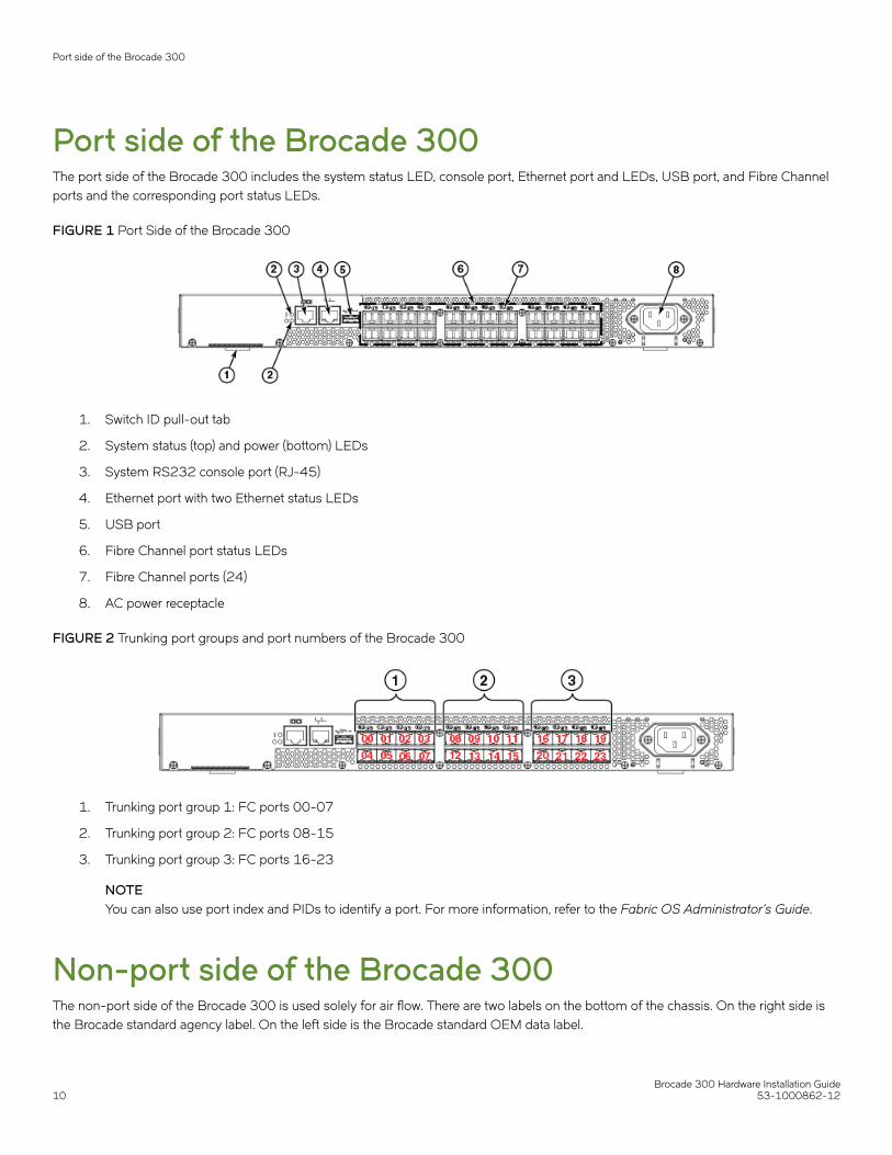
Port side of the Brocade 300The port side of the Brocade 300 includes the system status LED, console port, Ethernet port and LEDs, USB port, and Fibre Channelports and the corresponding port status LEDs.
FIGURE 1 Port Side of the Brocade 300
1. Switch ID pull-out tab
2. System status (top) and power (bottom) LEDs
3. System RS232 console port (RJ-45)
4. Ethernet port with two Ethernet status LEDs
5. USB port
6. Fibre Channel port status LEDs
7. Fibre Channel ports (24)
8. AC power receptacle
FIGURE 2 Trunking port groups and port numbers of the Brocade 300
1. Trunking port group 1: FC ports 00-07
2. Trunking port group 2: FC ports 08-15
3. Trunking port group 3: FC ports 16-23
NOTEYou can also use port index and PIDs to identify a port. For more information, refer to the Fabric OS Administrator's Guide.
Non-port side of the Brocade 300The non-port side of the Brocade 300 is used solely for air flow. There are two labels on the bottom of the chassis. On the right side isthe Brocade standard agency label. On the left side is the Brocade standard OEM data label.
Port side of the Brocade 300
Brocade 300 Hardware Installation Guide10 53-1000862-12

Supported fabric configurationsThe Brocade 300 is supported as an edge device in fabrics of up to 239 switches.
Ports on Demand licenseBrocade 300 can be purchased with 8, 16, or 24 licensed ports. As your needs increase, you can activate unlicensed ports bypurchasing and installing the Brocade Ports on Demand (POD) optional licensed product. After it has been installed, the license appearsin the licenseShow command output as Ports on Demand license .
By default, ports 0 through 7 are enabled on the Brocade 300. To enable ports 8 through 16, install a POD license key. To enable ports16 through 24, install another POD license.
To install a POD license, you can either use the supplied license key or generate a license key. Typically the switch is shipped with a paperpack that specifies the transaction key to use with the Software License Keys link. Use this transaction key on the Brocade Web site atwww.brocade.com /licensekeys and follow the instructions to generate the key. You can also use this site to generate other license keysfor your switch.
After you have installed the license keys, you must enable the ports. You can do so without disrupting switch operation by using theportEnable command on each port individually. Alternatively, you can disable and re-enable the switch to activate all portssimultaneously.
For detailed information on enabling additional ports using the POD license, refer to the Fabric OS Administrator’s Guide .
ISL trunking groupsThe Brocade 300 supports Interswitch Link (ISL) Trunking as a licensed feature. When this feature is enabled, you can create trunkedgroups of up to eight contiguous ports. This means that you can create up to three trunked groups that contain eight ports each.
The Fibre Channel ports on the Brocade 300 are numbered from left to right and color-coded into groups of eight to indicate whichports you can combine into trunked groups.
FIGURE 3 Trunking Groups
A. Trunk group 1: Ports 0 through 7
B. Trunk group 2: Ports 8 through 15
C. Trunk group 3: Ports 16 though 23
NOTEBrocade ISL Trunking is optional software that allows you to create trunking groups of ISLs between adjacent switches. Formore information about trunking, refer to the Fabric OS Administrator’s Guide
ISL trunking groups
Brocade 300 Hardware Installation Guide53-1000862-12 11

Managing the Brocade 300You can use the management functions built into the Brocade 300 to monitor the fabric topology, port status, physical status, and otherinformation to help you analyze switch performance and to accelerate system debugging.
The Brocade 300 automatically performs power-on-self-test (POST) each time it is turned on. Any errors are recorded in the error log.For more information about POST, see POST and boot specifications on page 63.
For information about upgrading the version of Fabric OS installed on your switch, refer to the Fabric OS Administrator’s Guide.
You can manage the Brocade 300 using any of the management options listed in the following table.
TABLE 1 Management Options for the Brocade 300 Switch
Management Tool Out-of-band Support
Command line interface (CLI)
Up to two admin sessions and four user sessions simultaneously. For more information,refer to the Fabric OS Administrator’s Guide and the Fabric OS Command ReferenceManual .
Ethernet or serial connection
Brocade Web Tools
For information, refer to the Web Tools Administrator’s Guide .
Ethernet or serial connection
Standard SNMP applications
For information, refer to the MIB Reference Manual .
Ethernet or serial connection
Brocade Fabric Manager (option to purchase)
For information, refer to the Fabric Manager Administrator’s Guide .
Ethernet or serial connection
Management Server
For information, refer to the Fabric OS Administrator’s Guide and the Fabric OSCommand Reference Manual .
Ethernet or serial connection
EFCM (option to purchase)
For information, refer to the EFCM documentation set.
Ethernet or serial connection
NOTETo achieve in-band support for IP over Fibre Channel, the software must be run on both the HBA and the switch, and it mustbe supported by both the HBA and HBA driver
Managing the Brocade 300
Brocade 300 Hardware Installation Guide12 53-1000862-12

Preparing for Installation• Installation precautions....................................................................................................................................................................................13• Facility requirements.........................................................................................................................................................................................14• Environmental considerations...................................................................................................................................................................... 15• Recommendations for cable management............................................................................................................................................ 15• Items included with the Brocade 300.......................................................................................................................................................15
Installation precautionsWhen using this product, observe all danger, caution, and attention notices in this manual. The notices are accompanied by symbols thatrepresent the severity of the safety condition.
NOTERefer to Cautions and Danger Notices on page 79 for translations of safety notices for this product.
General precautionsDANGERThe procedures in this manual are for qualified service personnel.
CAUTIONChanges or modifications made to this device that are not expressly approved by the party responsible for compliancecould void the user's authority to operate the equipment.
Power precautionsTo install and operate the switch successfully, ensure the following:
• The primary outlet is correctly wired, protected by a circuit breaker, and grounded in accordance with local electrical codes.
• Connect the power cord only to a grounded outlet.
DANGERMake sure that the power source circuits are properly grounded, then use the power cord supplied with the deviceto connect it to the power source.
• The supply circuit, line fusing, and wire size are adequate, as specified by the electrical rating on the switch nameplate.
• This product is designed for an IT power system with phase-to-phase voltage of 230V. After operation of the protective device,the equipment is still under voltage if it is connected to an IT power system.
DANGERTo avoid high voltage shock, do not open the device while the power is on.
• The power supply standards provided in Brocade 300 Technical Specifications on page 0 are met.
Brocade 300 Hardware Installation Guide53-1000862-12 13

RTC battery precautionsDo not attempt to replace the real-time clock (RTC) battery. There is danger of explosion if the battery is incorrectly replaced or disposedof. Contact your switch supplier if the real-time clock begins to lose time.
DANGERBatteries used for RTC/NVRAM backup are not located in operator-access areas. There is a risk of explosion if a batteryis replace by an incorrect type. Dispose of used components containing batteries according to the local ordinance andregulations.
Laser precautionsSFPs contain Class 1 lasers. Following are precautions that you should observe.
DANGERAll fiber-optic interfaces use Class 1 lasers.
DANGERLaser Radiation. Do Not View Directly with Optical Instruments. Class 1M Laser Products.
DANGERUse only optical transceivers that are qualified by Brocade Communications Systems LLC and comply with the FDAClass 1 radiation performance requirements defined in 21 CFR Subchapter I, and with IEC 60825 and EN60825. Opticalproducts that do not comply with these standards might emit light that is hazardous to the eyes.
Facility requirementsThe following table provides the facilities requirements that must be met for the Brocade 300.
TABLE 2 Facility Requirements
Type Requirements
Electrical • Primary AC input 100-240 VAC, 2.0A, 47-63 Hz; switchautosenses input voltage
• Adequate supply circuit, line fusing, and wire size, as specifiedby the electrical rating on the switch nameplate
• Circuit protected by a circuit breaker and grounded inaccordance with local electrical codes
Refer to Brocade 300 Technical Specifications on page 0 for completepower supply specifications.
Thermal • A minimum air flow of 39.1 cubic meters/hour (23 cubic ft/min.) available in the immediate vicinity of the switch
• Ambient air temperature not exceeding 40 ° C (104 ° F) whilethe switch is operating
Rack installation • One unit (1U) in a 48.3 cm (19-inches) rack
• All equipment in rack grounded through a reliable branch circuitconnection
• Additional weight of switch not to exceed the rack's weight limits
• Rack secured to ensure stability in case of unexpectedmovement
Facility requirements
Brocade 300 Hardware Installation Guide14 53-1000862-12

Environmental considerationsFor successful installation and operation of the switch, ensure that the following environmental requirements are met:
• At a minimum, adequate cooling requires that you install the switch with the non-port side, which contains the air intake vents,facing the cool-air aisle.
• A minimum of 30.6 cubic meters/hour (18 cubic ft/min) and a maximum of 39.1 cubic meters/hour (23 cubic ft/min) of airflow is available to the air intake vents on the non-port side of the switch.
CAUTIONMake sure the airflow around the front, and back of the device is notrestricted.
• Ensure that temperature requirements are met.
CAUTIONDo not install the device in an environment where the operating ambient temperature might exceed 40°C (104°F).
Recommendations for cable managementThe minimum bend radius for a 50 micron cable is 5.08 cm (2 inches) under full tensile load and 3.05 cm (1.2 inches) with no tensileload.
Cables can be organized and managed in a variety of ways: for example, using cable channels on the sides of the rack or patch panels tominimize cable management. Following is a list of recommendations:
NOTEYou should not use tie wraps with optical cables because they are easy to over tighten.
CAUTIONBefore plugging a cable into any port, be sure to discharge the voltage stored on the cable by touching the electricalcontacts to ground surface.
• Plan for rack space required for cable management before installing the switch.
• Leave at least 1 m (3.28 ft) of slack for each port cable. This provides room to remove and replace the switch, allows forinadvertent movement of the rack, and helps prevent the cables from being bent to less than the minimum bend radius.
• If you are using Brocade ISL Trunking, consider grouping cables by trunking groups. The cables used in trunking groups mustmeet specific requirements, as described in the Fabric OS Administrator’s Guide.
• For easier maintenance, label the fiber optic cables and record the devices to which they are connected.
• Keep LEDs visible by routing port cables and other cables away from the LEDs.
• Use hook and loop straps to secure and organize fiber optic cables.
Items included with the Brocade 300The following items are included with the standard shipment of the Brocade 300. When you open the Brocade 300 packaging, verifythat these items are included in the package and that no damage has occurred during shipping:
• One Brocade 300 Fibre Channel switch
Items included with the Brocade 300
Brocade 300 Hardware Installation Guide53-1000862-12 15

• An accessory kit containing:
– Serial cable with an RJ-45 connector– 6 ft. Power Cord– Rubber feet, required for setting up the switch as a standalone unit
Items included with the Brocade 300
Brocade 300 Hardware Installation Guide16 53-1000862-12

Mounting the Device• Mounting options...............................................................................................................................................................................................17• Installing a standalone Brocade 300........................................................................................................................................................ 17• EIA rack installation for a Brocade 300................................................................................................................................................... 17• Installing the 1U, 1.5U, and 2U Mid-Mount Kit for Two-Post Racks (XBR-000165, XBR-000175,
and XBR-R000292)....................................................................................................................................................................................... 18• Installing the 1U and 2U Fixed-Mount Rack Kit for Four-Post Racks (XBR-R000162)...................................................23• Slide Rack Mount Kit (XBR-R000070)...................................................................................................................................................30• Installing the 1U and 2U Non-Port Side Fixed-Mount Rack Kit (15"-20") for Four-Post Racks
(XNA-000072 and XNA-100072)..........................................................................................................................................................47
Mounting optionsYou can install the Brocade 300 switch in the following ways:
1. As a standalone unit on a flat surface.
2. In an EIA rack using a fixed-rail rack mount kit. The optional fixed-rail rack mount kit can be ordered from your switch retailer.
3. In an EIA rack sing an optional slide-rail rack mount kit. The optional slide-rail rack mount kit can be ordered from your switchretailer.
Installing a standalone Brocade 300Perform this task to install the Brocade 300 as a standalone unit.
1. Unpack the Brocade 300.
2. Apply the adhesive rubber feet. Applying the rubber feet onto the switch helps prevent the switch from sliding off the supportingsurface.
a) Clean the indentations at each corner of the bottom of the switch to ensure that they are free of dust or other debris thatmight lessen the adhesion of the feet.
b) With the adhesive side against the chassis, place one rubber foot in each indentation and press into place.
3. Place the switch on a flat, sturdy surface.
4. Provide power to the switch as described in Providing power to the switch on page 55.
NOTEDo not connect the switch to the network until the IP address is correctly set. For instructions on how to set the IPaddress, see Initial Setup and Verification on page 55
EIA rack installation for a Brocade 300The rack mount kit can be installed in two ways:
• To allow the port side of the switch to slide out of the exhaust-air side of the rack. In this installation, the port side of the switch isflush with the edge of the rack.
Brocade 300 Hardware Installation Guide53-1000862-12 17

• To allow the non-port side of the switch to slide out the cool-air side of the rack. In this installation, the port side of the switch isset 7.62 cm (3 inches) back from the edge of the rack, allowing a more gradual bend in the fiber optic cables.
Whichever mounting method you choose, follow the installation instructions shipped with the appropriate rack mount kit.
EIA rack considerationsFor successful installation and operation of the switch in a EIA rack, ensure the following requirements are met:
• The rack must be a standard EIA rack.
• Plan a rack space that is 1 rack unit - 4.45 cm (1.75 inches) high, 48.3 cm (19 inches) wide.
• Ground all equipment in the rack through a reliable branch circuit connection and maintain ground at all times. Do not rely on asecondary connection to a branch circuit, such as a power strip.
• Ensure that airflow and temperature requirements are met on an ongoing basis, particularly if the switch is installed in a closedor multi-rack assembly.
• Verify that the additional weight of the switch does not exceed the rack’s weight limits or unbalance the rack in any way.
• DANGERMake sure the rack housing the device is adequately secured to prevent it from becoming unstable or falling over.
Installing the 1U, 1.5U, and 2U Mid-Mount Kit forTwo-Post Racks (XBR-000165, XBR-000175, andXBR-R000292)Use the following instructions to install a fixed-port device in a mid-mount configuration in a two-post rack using the 1U, 1.5U, and 2UMid-Mount Kit for Two-Post Racks (XBR-000165, XBR-000175, and XBR-R000292).
Observe the following when mounting this device:
• Two people are required to install the device in a rack. One person holds the device, while the other secures the device to therack.
• Before mounting your device, review any specific installation and facility requirements in this Hardware Installation Guide.
• Hardware devices illustrated in these procedures are only for reference and may not depict the device you are installing into therack.
Time and items requiredAllow 15 to 30 minutes to complete the installation procedure.
The following items are required to install a device using the 1U, 1.5U, or 2U Mid-Mount Kit for Two-Post Racks (XBR-000165,XBR-000175, and XBR-R000292).
• #2 Phillips torque screwdriver
• 1/4 inch slotted-blade torque screwdriver
NOTEYou may need two people to install the device, one to support the device, while the other secures it into the rack.
Installing the 1U, 1.5U, and 2U Mid-Mount Kit for Two-Post Racks (XBR-000165, XBR-000175, and XBR-R000292)
Brocade 300 Hardware Installation Guide18 53-1000862-12

CAUTIONUse the screws specified in the procedure. Using longer screws can damage thedevice.
Parts listThe following parts are provided with the 1U, 1.5U, or 2U Mid-Mount Rack Kit for Two-Post Racks (XBR-000165, XBR-000175, andXBR-R000292).
NOTEDepending on the device type, not all parts may be used in an installation.
FIGURE 4 Rack kit parts
1. Bracket, front right and back left
2. Bracket, front left and back right
3. Screw, 8-32 x 5/16-in., panhead Phillips (12)
4. Screw, 6-32 x 1/4-in., flathead Phillips (8)
5. Screw, 10-32 x 5/8-in., panhead Phillips (8)
6. Retainer nut, 10-32 (8)
Installing the 1U, 1.5U, and 2U Mid-Mount Kit for Two-Post Racks (XBR-000165, XBR-000175, and XBR-R000292)
Brocade 300 Hardware Installation Guide53-1000862-12 19
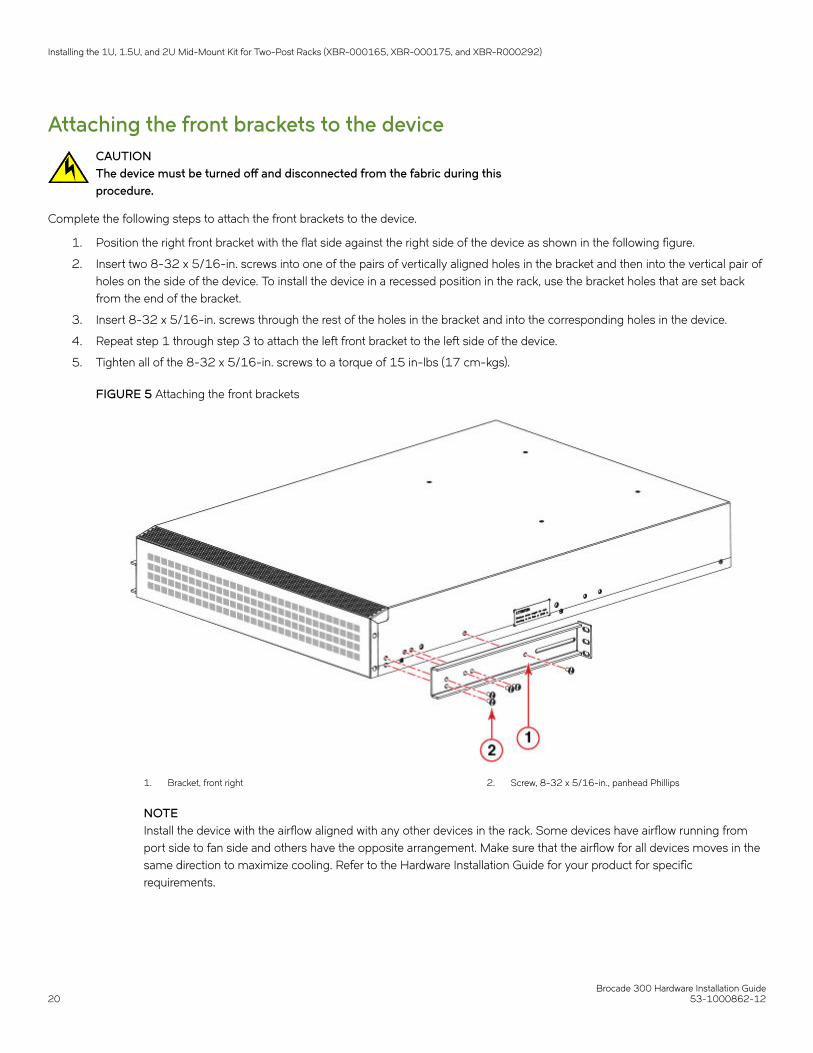
Attaching the front brackets to the deviceCAUTIONThe device must be turned off and disconnected from the fabric during thisprocedure.
Complete the following steps to attach the front brackets to the device.
1. Position the right front bracket with the flat side against the right side of the device as shown in the following figure.
2. Insert two 8-32 x 5/16-in. screws into one of the pairs of vertically aligned holes in the bracket and then into the vertical pair ofholes on the side of the device. To install the device in a recessed position in the rack, use the bracket holes that are set backfrom the end of the bracket.
3. Insert 8-32 x 5/16-in. screws through the rest of the holes in the bracket and into the corresponding holes in the device.
4. Repeat step 1 through step 3 to attach the left front bracket to the left side of the device.
5. Tighten all of the 8-32 x 5/16-in. screws to a torque of 15 in-lbs (17 cm-kgs).
FIGURE 5 Attaching the front brackets
1. Bracket, front right 2. Screw, 8-32 x 5/16-in., panhead Phillips
NOTEInstall the device with the airflow aligned with any other devices in the rack. Some devices have airflow running fromport side to fan side and others have the opposite arrangement. Make sure that the airflow for all devices moves in thesame direction to maximize cooling. Refer to the Hardware Installation Guide for your product for specificrequirements.
Installing the 1U, 1.5U, and 2U Mid-Mount Kit for Two-Post Racks (XBR-000165, XBR-000175, and XBR-R000292)
Brocade 300 Hardware Installation Guide20 53-1000862-12

Attaching the device to a rackComplete the following steps to install the device in the rack.
1. Position the device in the rack as shown in the following figure, providing temporary support under the device until the rail kit issecured to the rack.
2. Attach the right front bracket to the right rack rail using three 10-32 x 5/8-in. screws and three 10-32 retainer nuts.
3. Attach the left front bracket to the left rack rail using three 10-32 x 5/8-in. screws and three 10-32 retainer nuts.
4. Tighten all the 10-32 x 5/8-in. screws to a torque of 25 in-lbs (29 cm-kgs)
FIGURE 6 Attaching the device to a rack
1. Bracket, front right
2. Screw, 10-32 x 5/8-in., panhead Phillips
3. Retainer nut, 10-32
Attaching the rear brackets to the rackNOTEDo not use the rear brackets for the Brocade 6505, 6510, or 6520 switches.
Complete the following steps to attach the rear brackets to the rack.
1. Position the right rear bracket in the right rear of the device as shown in the following figure.
2. Attach the brackets using three 10-32 x 5/8-in. screws and 10-32 retainer nuts.
3. Repeat step 1 and step 2 to attach the left rear bracket.
Installing the 1U, 1.5U, and 2U Mid-Mount Kit for Two-Post Racks (XBR-000165, XBR-000175, and XBR-R000292)
Brocade 300 Hardware Installation Guide53-1000862-12 21

4. Adjust the brackets to the rack depth and tighten the screws to a torque of 25 in-lbs (29 cm-kgs).
FIGURE 7 Attaching the rear brackets to a rack
1. Bracket, front right
2. Retainer nut, 10-32
3. Screw, 10-32 x 5/8-in., flathead Phillips
4. Bracket, rear right
Attaching the rear brackets to the deviceComplete the following steps to attach the rear brackets to the device.
1. Align the right rear bracket to the right rear of the device and use two 8-32 x 5/16-in. screws to attach the bracket to the deviceas shown in the following figure.
2. Align the left rear bracket to the left rear of the device and use two 8-32 x 5/16-in. screws to attach the bracket to the device asshown in the following figure.
Installing the 1U, 1.5U, and 2U Mid-Mount Kit for Two-Post Racks (XBR-000165, XBR-000175, and XBR-R000292)
Brocade 300 Hardware Installation Guide22 53-1000862-12

3. Tighten all the screws to a torque of 9 in-lbs (10 cm-kgs).
FIGURE 8 Attaching the rear brackets to the device
1. Screw, 8-32 x 5/16-in., panhead Phillips
Installing the 1U and 2U Fixed-Mount Rack Kit forFour-Post Racks (XBR-R000162)Use the following instructions to install a fixed-port device in a fixed-mount configuration using the 1U and 2U Fixed-Mount Rack Kit forFour-Post Racks (XBR-R000162).
Observe the following when mounting this device:
• Two people are required to install the device in a rack. One person holds the device, while the other secures the device to therack.
• Use Electronic Industries Association (EIA) standard racks.
• Before mounting your device, review any specific installation and facility requirements in this Hardware Installation Guide.
• Hardware devices illustrated in these procedures are only for reference and may not depict the device you are installing into therack.
Time and items requiredAllow 15 to 30 minutes to complete the installation procedure.
The following items are required to install a device using the 1U and 2U Fixed-Mount Rack Kit for Four-Post Racks (XBR-R000162).
• #2 Phillips torque screwdriver
• 1/4-inch slotted-blade torque screwdriver
Installing the 1U and 2U Fixed-Mount Rack Kit for Four-Post Racks (XBR-R000162)
Brocade 300 Hardware Installation Guide53-1000862-12 23

NOTEYou may need two people to install the device, one to support the device, while the other secures it into the rack.
CAUTIONUse the screws specified in the procedure. Using longer screws can damage thedevice.
Parts listThe following parts are provided with the 1U and 2U Fixed-Mount Rack Kit for Four-Post Racks (XBR-R000162).
Installing the 1U and 2U Fixed-Mount Rack Kit for Four-Post Racks (XBR-R000162)
Brocade 300 Hardware Installation Guide24 53-1000862-12

FIGURE 9 Rack kit parts
1. Bracket, front right
2. Bracket, front left
3. Bracket, rear left
4. Bracket, rear right
5. Screw, 8-32 x 5/16-in., panhead Phillips (12)
6. Screw, 6-32 x 1/4-in., flathead Phillips (8)
7. Screw, 10-32 x 5/8-in., panhead Phillips (8)
8. Retainer nut, 10-32 (8)
NOTENot all parts may be used with certain installations depending on the device type.
NOTEAlthough this document describes how to install single-height (1U) and double-height (2U) devices, the illustrations show asingle-height device as a typical installation.
Installing the 1U and 2U Fixed-Mount Rack Kit for Four-Post Racks (XBR-R000162)
Brocade 300 Hardware Installation Guide53-1000862-12 25

Attaching the front bracketsCAUTIONThe device must be turned off and disconnected from the fabric during thisprocedure.
Complete the following steps to attach the front brackets to the device.
1. Position the right front bracket with the flat side against the right side of the device, as shown in the following figure.
2. Insert two 8-32 x 5/16-in. screws into one of the pairs of vertically aligned holes in the bracket and then into the pair of holeson the side of the device. To install the device in a recessed position in the rack, use the bracket holes that are set back from theend of the bracket.
3. Insert additional 8-32 x 5/16-in. screws through the holes in the bracket and into the corresponding holes in the device. Thenumber of screws may vary depending on the device model.
4. Repeat step 1 through step 3 to attach the left front bracket to the left side of the device.
5. Tighten all the 8-32 x 5/16-in. screws to a torque of 15 in-lbs (17 cm-kgs).
FIGURE 10 Attaching the front brackets
1. Bracket, front right 2. Screw, 8-32 x 5/16-in., panhead Phillips
Installing the 1U and 2U Fixed-Mount Rack Kit for Four-Post Racks (XBR-R000162)
Brocade 300 Hardware Installation Guide26 53-1000862-12

Installing the device in the rackComplete the following steps to install the device in the rack.
1. Position the device in the rack, as shown in the following figure, providing temporary support under the device until the rail kit issecured to the rack.
2. Attach the right front bracket to the right front rack post using two 10-32 x 5/8-in. screws and two retainer nuts.
3. Attach the left front bracket to the left front rack post using two 10-32 x 5/8-in. screws and two retainer nuts.
Installing the 1U and 2U Fixed-Mount Rack Kit for Four-Post Racks (XBR-R000162)
Brocade 300 Hardware Installation Guide53-1000862-12 27
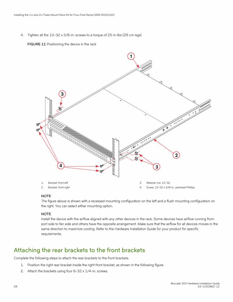
4. Tighten all the 10-32 x 5/8-in. screws to a torque of 25 in-lbs (29 cm-kgs)
FIGURE 11 Positioning the device in the rack
1. Bracket, front left
2. Bracket, front right
3. Retainer nut, 10-32
4. Screw, 10-32 x 5/8-in., panhead Phillips
NOTEThe figure above is shown with a recessed mounting configuration on the left and a flush mounting configuration onthe right. You can select either mounting option.
NOTEInstall the device with the airflow aligned with any other devices in the rack. Some devices have airflow running fromport side to fan side and others have the opposite arrangement. Make sure that the airflow for all devices moves in thesame direction to maximize cooling. Refer to the Hardware Installation Guide for your product for specificrequirements.
Attaching the rear brackets to the front bracketsComplete the following steps to attach the rear brackets to the front brackets.
1. Position the right rear bracket inside the right front bracket, as shown in the following figure.
2. Attach the brackets using four 6-32 x 1/4-in. screws.
Installing the 1U and 2U Fixed-Mount Rack Kit for Four-Post Racks (XBR-R000162)
Brocade 300 Hardware Installation Guide28 53-1000862-12

3. Repeat step 1 and step 2 to attach the left rear bracket to the left front bracket.
4. Adjust the brackets to the rack depth and tighten all the 6-32 x 1/4-in. screws to a torque of 9 in-lbs (10 cm-kgs).
FIGURE 12 Attaching the rear brackets to the front brackets
1. Bracket, front right
2. Screw, 6-32 x 1/4-in., flathead Phillips
3. Bracket, rear right
Attaching the rear brackets to the rack postsComplete the following steps to attach the rear brackets to the rack posts.
1. Attach the right rear bracket to the right rear rack post using two 10-32 x 5/8-in. screws and two retainer nuts, as shown in thefollowing figure.
2. Attach the left rear bracket to the left rear rack post using two 10-32 x 5/8-in. screws and two retainer nuts.
Installing the 1U and 2U Fixed-Mount Rack Kit for Four-Post Racks (XBR-R000162)
Brocade 300 Hardware Installation Guide53-1000862-12 29
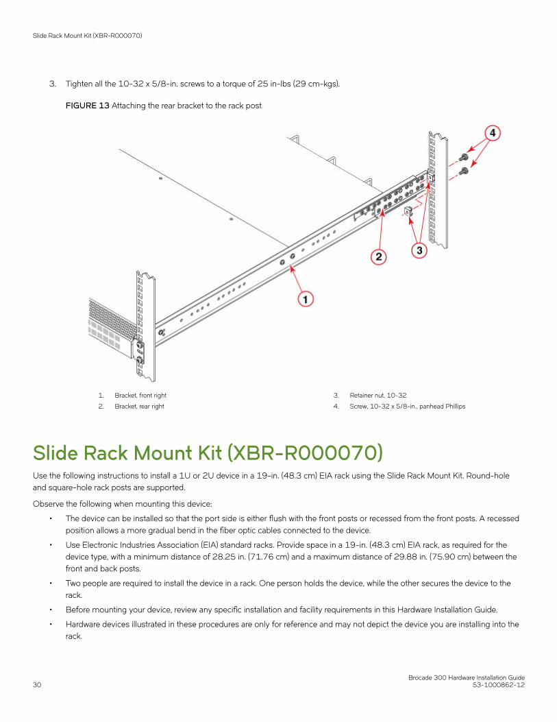
3. Tighten all the 10-32 x 5/8-in. screws to a torque of 25 in-lbs (29 cm-kgs).
FIGURE 13 Attaching the rear bracket to the rack post
1. Bracket, front right
2. Bracket, rear right
3. Retainer nut, 10-32
4. Screw, 10-32 x 5/8-in., panhead Phillips
Slide Rack Mount Kit (XBR-R000070)Use the following instructions to install a 1U or 2U device in a 19-in. (48.3 cm) EIA rack using the Slide Rack Mount Kit. Round-holeand square-hole rack posts are supported.
Observe the following when mounting this device:
• The device can be installed so that the port side is either flush with the front posts or recessed from the front posts. A recessedposition allows a more gradual bend in the fiber optic cables connected to the device.
• Use Electronic Industries Association (EIA) standard racks. Provide space in a 19-in. (48.3 cm) EIA rack, as required for thedevice type, with a minimum distance of 28.25 in. (71.76 cm) and a maximum distance of 29.88 in. (75.90 cm) between thefront and back posts.
• Two people are required to install the device in a rack. One person holds the device, while the other secures the device to therack.
• Before mounting your device, review any specific installation and facility requirements in this Hardware Installation Guide.
• Hardware devices illustrated in these procedures are only for reference and may not depict the device you are installing into therack.
Slide Rack Mount Kit (XBR-R000070)
Brocade 300 Hardware Installation Guide30 53-1000862-12

Safety precautionsDANGERUse safe lifting practices when moving the product.
DANGERMount the devices you install in a rack as low as possible. Place the heaviest device at the bottom and progressively placelighter devices above.
CAUTIONMake sure the airflow around the front, and back of the device is notrestricted.
CAUTIONUse the screws specified in the procedure. Using longer screws can damage thedevice.
CAUTIONNever leave tools inside the chassis.
CAUTIONDo not use the port cover tabs to lift the module. They are not designed to support the weight of the module, which can falland be damaged.
CAUTIONTo prevent damage to the chassis and components, never attempt to lift the chassis using the fan or power supply handles.These handles were not designed to support the weight of the chassis.
Time and items requiredAllow 15 to 30 minutes to complete this procedure.
The following tools are required to install a device using the Slide Rack Mount Kit:
• #2 Phillips torque screwdriver
• 11/32-inch wrench
• 1/4-inch slotted-blade torque screwdriver
Parts listThe following parts are provided with the 1U and 2U Slide-Mount Rack Kit for Four-Post Racks (XBR-R000070).
NOTEUse the screws specified for use with the device. Longer screws can damage thedevice.
NOTEDepending on the device type, not all parts may be used in an installation.
Slide Rack Mount Kit (XBR-R000070)
Brocade 300 Hardware Installation Guide53-1000862-12 31

FIGURE 14 Rack kit parts (1 of 4)
1. Three-hole slide mount L-bracket (4)
2. Locking hex nut, 8-32 (8)
3. Slide assembly, containing one inner and one outer slide rail, with Items 2,3, 4, and 5 installed on the outer slide rail (each slide assembly is baggedseparately) (2)
4. Slotted screw, 8-32 x 3/8 in., zinc (8)
5. Power cord clip (6)
FIGURE 15 Rack kit parts(2 of 4)
1. Phillips screw, 10-32 x 1/2 in., black (12)
2. Three-hole rack nut bar, 8-32 (4)
3. Alignment washer (12)
4. Retainer nut, 10-32 (12)
Slide Rack Mount Kit (XBR-R000070)
Brocade 300 Hardware Installation Guide32 53-1000862-12

FIGURE 16 Rack kit parts (3 of 4)
1. Left rack mount bracket (unexpected movement safety bracket for portside) (1)
2. Right rack mount bracket (unexpected movement safety bracket for portside) (1)
3. Alternate left mount bracket (unexpected movement safety bracket forport side) (1)
4. Alternate right mount bracket (unexpected movement safety bracket forport side) (1)
5. Phillips screw, 8-32 x 1/4 in., black (4)
6. Slotted screw, 8-32 x 3/8 in., zinc (4)
FIGURE 17 Rack kit parts (4 of 4)
1. Back rack mount bracket (unexpected movement safety bracket for non-port side) (2)
2. Phillips screw, 8-32 x 3/16 in., zinc (12)
3. Locking hex nut, 8-32 (4)
4. Slotted screw, 8-32 x 3/8 in., zinc (4)
Installing the deviceNOTEThe device must be turned off and disconnected from the fabric during thisprocedure.
NOTETwo people are required to install the device in a rack. One person can hold the device while the other attaches it to the rack.
NOTEAlthough this document describes how to install 1U, 1.5U, or 2U devices, the illustrations show a 1.5U device.
Complete the following tasks to install the device in a rack.
Preparing the slide assembliesPerform the following steps to prepare both slide assemblies for installation.
1. Locate the slide assembly in the kit, as shown in the following figure. The slide assembly comes fully assembled and includes allof the parts shown in the figure.
2. Pull the inner slide rail out until the lock engages. Refer to the following figure.
Slide Rack Mount Kit (XBR-R000070)
Brocade 300 Hardware Installation Guide53-1000862-12 33

3. Press the lock-release lever located inside the inner slide rail and pull the inner rail away from the outer rail.
4. Repeat these steps for the second slide assembly.
NOTEThe device must be turned off and disconnected from the fabric during the installationprocedure.
FIGURE 18 Pulling the slide rails apart
1. Inner slide rail
2. Lock-release lever
3. Slide assembly
Attaching the inner slide rails to the devicePerform the following steps to attach the inner slide rails to the device.
1. Position an inner slide rail with the flat side against the device and the end containing the lock-release lever toward the non-portside of the device.
2. Align the rail holes with the holes drilled in the side of the device, as shown in the following figure.
NOTEThe hole pattern is identical for all 1U, 1.5U, and 2U devices.
3. Attach the rail using three Phillips 8-32 x 3/16-in. screws.
4. Tighten the screws to a torque of 15 in-lbs (17 cm-kgs).
Slide Rack Mount Kit (XBR-R000070)
Brocade 300 Hardware Installation Guide34 53-1000862-12

5. Repeat these steps for the inner slide rail on the other side of the device.
FIGURE 19 Installing the inner rail to allow a device to slide out of the port side
1. Phillips screw, 8-32 x 3/16 in., zinc
NOTETwo people are required to install the device in a rack. One person can hold the device while the other attaches it to therack.
Attaching the rack mount bracketsPerform the following steps to attach the rack mount brackets.
1. Position the right rack mount bracket next to the right side of the device, as shown in the following figure.
2. Attach the right rack mount bracket to the device using two slotted-head 8-32 x 3/8 in. screws. You can use either the regularrack mount bracket or the alternate rack mount bracket. Be sure to be consistent on both sides of the device.
For recessed mounting, you can use the back rack mount brackets on the front instead of the left and right rack mount brackets.
3. Tighten the screws to a torque of 15 in-lbs (17 cm-kgs).
Slide Rack Mount Kit (XBR-R000070)
Brocade 300 Hardware Installation Guide53-1000862-12 35
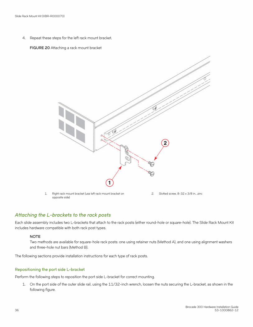
4. Repeat these steps for the left rack mount bracket.
FIGURE 20 Attaching a rack mount bracket
1. Right rack mount bracket (use left rack mount bracket onopposite side)
2. Slotted screw, 8-32 x 3/8 in., zinc
Attaching the L-brackets to the rack postsEach slide assembly includes two L-brackets that attach to the rack posts (either round-hole or square-hole). The Slide Rack Mount Kitincludes hardware compatible with both rack post types.
NOTETwo methods are available for square-hole rack posts: one using retainer nuts (Method A), and one using alignment washersand three-hole nut bars (Method B).
The following sections provide installation instructions for each type of rack posts.
Repositioning the port side L-bracket
Perform the following steps to reposition the port side L-bracket for correct mounting.
1. On the port side of the outer slide rail, using the 11/32-inch wrench, loosen the nuts securing the L-bracket, as shown in thefollowing figure.
Slide Rack Mount Kit (XBR-R000070)
Brocade 300 Hardware Installation Guide36 53-1000862-12

2. Extend the end of the bracket beyond the end of the slide rail by 5/8 inch.
Repositioning allows the rack mount brackets to align with the rack posts.
FIGURE 21 Repositioning the L-brackets
1. Three-hole slide mount L-bracket
2. Locking hex nut, 8-32
3. Outer slide rail
4. 5/8-inch reposition
Attaching the rail to round-hole rack posts
Perform the following steps to install the round-hole hardware.
1. Position the outer slide rail inside the rack posts with the closed ends of the slide rail toward the non-port side of the rack, asshown in the following figure.
2. Loosen and adjust the position of the non-port side L-bracket as necessary.
NOTEIf side rack access is not available, measure the depth of the rack, loosen the L-bracket on the non-port side, andadjust the bracket position until the total rail length matches the rack depth.
3. Attach the L-brackets to the rack posts using five Phillips 10-32 x 1/2 in. screws and two of the three-hole rack nut bars.
NOTELeave the middle hole empty on the port side for securing the rack mount bracket later (refer to Inserting the device inthe rack on page 42).
4. Tighten the screws to 15 in-lbs (17 cm-kgs).
Slide Rack Mount Kit (XBR-R000070)
Brocade 300 Hardware Installation Guide53-1000862-12 37

5. Repeat these steps for the other rail.
FIGURE 22 Attaching outer slide rails to round-hole rack posts
1. Phillips screw, 10-32 x 1/2 in., black (5 each side)
2. Three-hole slide mount L-bracket (2 each side)
3. Rack post (port side)
4. Outer slide rail
5. Rack post (non-port side)
6. Three-hole slide mount L-bracket
7. Three-hole rack nut bar, 8-32 (2 each side)
Attaching the rail to square-hole rack posts (Method A)
Perform the following steps to install the square-hole hardware using Method A.
1. Position the outer slide rail inside the rack posts with the closed ends of the slide rail toward the non-port side of the rack, asshown in the following figure.
Slide Rack Mount Kit (XBR-R000070)
Brocade 300 Hardware Installation Guide38 53-1000862-12

2. Loosen and adjust the position of the non-port side L-bracket as necessary.
NOTEIf side rack access is not available, measure the depth of the rack, loosen the L-bracket on the non-port side, andadjust the bracket position until the total rail length matches the rack depth.
3. Attach the L-brackets to the rack posts using five Phillips 10-32 x 1/2 in. screws and five retainer nuts.
NOTELeave the middle hole empty on the port side for securing the rack mount bracket later (refer to Inserting the device inthe rack on page 42).
4. Tighten the screws to 15 in-lbs (17 cm-kgs).
Slide Rack Mount Kit (XBR-R000070)
Brocade 300 Hardware Installation Guide53-1000862-12 39

5. Repeat these steps for the other rail.
FIGURE 23 Method A for attaching outer slide rails to square-hole rack posts
1. Phillips screw, 10-32 x 1/2 in., black (5 each side)
2. Three-hole slide mount L-bracket (2 each side)
3. Rack post (port side)
4. Outer slide rail
5. Rack post (non-port side)
6. Three-hole slide mount L-bracket
7. Retainer nut, 10-32 (5 each side)
Attaching the rail to square-hole rack posts (Method B)
Perform the following steps to install the square-hole hardware using Method B.
1. Position the outer slide rail inside the rack posts with the closed ends of the slide rail toward the non-port side of the rack, asshown in the following figure.
Slide Rack Mount Kit (XBR-R000070)
Brocade 300 Hardware Installation Guide40 53-1000862-12

2. Loosen and adjust the position of the non-port side L-bracket as necessary.
NOTEIf side rack access is not available, measure the depth of the rack, loosen the L-bracket on the non-port side, andadjust the bracket position until the total rail length matches the rack depth.
3. Attach the L-brackets to the rack posts using five Phillips 10-32 x 1/2 in. screws, six alignment washers, and two of the three-hole rack nut bars.
NOTELeave the middle hole empty on the port side for securing the rack mount bracket later (refer to Inserting the device inthe rack on page 42); however, position an alignment washer between the L-bracket and the rack post.
4. Tighten the screws to 15 in-lbs (17 cm-kgs).
5. Repeat these steps for the other rail.
FIGURE 24 Method B for attaching outer slide rails to square-hole rack posts
1. Phillips screw, 10-32 x 1/2 in., black (5 each side)
2. Three-hole slide mount L-bracket (2 each side)
3. Rack post (port side)
4. Outer slide rail
5. Three-hole slide mount L-bracket
6. Alignment washer (6 each side)
7. Rack post (non-port side)
8. Three-hole rack nut bar, 8-32 (2 each side)
Slide Rack Mount Kit (XBR-R000070)
Brocade 300 Hardware Installation Guide53-1000862-12 41

Inserting the device in the rackPerform the following steps to install the device in the rack.
1. Position the power cord clips on the outer surface of both outer slide rails, as shown in the following figure.
Ensure that the clips do not interfere with the movement of the rails. Position all the clips either with the tabs above or with thetabs below the rail.
FIGURE 25 Attaching the power cord clips
1. Three-hole slide mount L-bracket
2. Slide assembly
3. Power cord clips (3 each side)
Slide Rack Mount Kit (XBR-R000070)
Brocade 300 Hardware Installation Guide42 53-1000862-12

2. Insert the power cords into the power cord clips, with the power cord prongs pointing toward the power source, as shown in thefollowing figure.
NOTEAllow a minimum service loop of six inches at the device to ensure freedom to plug and unplug the power cords.Ensure that the power cords route completely outside of the slide rails.
NOTEEnsure that the power cords align in the clips and do not fall inside the slide rails. To prevent the cords from beingpulled out of the clips, unplug the cords from the device before moving the device on the slide rails.
FIGURE 26 Inserting the power cords in clips
1. Power cord 2. Slide assembly
3. Position the device next to the rack; align and insert the inner rails inside the outer rails, as shown in the following figure.
Slide Rack Mount Kit (XBR-R000070)
Brocade 300 Hardware Installation Guide53-1000862-12 43

4. Gently slide the device into the rack. If there is any resistance, pull the device out of the rack and realign the slide rails.
NOTECheck the rail alignment by sliding the device out and back into the rack.
FIGURE 27 Inserting the device
1. device
2. Slide assembly closed end
3. Outer slide rail
4. Slide assembly open end
5. Inner slide rail
6. Lock-release lever
Slide Rack Mount Kit (XBR-R000070)
Brocade 300 Hardware Installation Guide44 53-1000862-12

5. Secure the rack mount brackets to the rack posts using one Phillips 10-32 x 1/2 in. screw per bracket and tighten the screws toa torque of 25 in-lbs (29 cm-kgs).
For square-hole rack post Method A installations, use the remaining retainer nut to secure the screw.
Refer to Figure 28 for a round-hole rack post; refer to Figure 29 (Method A) or Figure 30 (Method B) for a square-hole rackpost.
FIGURE 28 Securing rack mount brackets for round-hole rack posts
1. Right rack mount bracket
2. Rack post
3. Three-hole rack nut bar, 8-32
4. Phillips screw, 10-32 x 1/2 in., black
FIGURE 29 Method A for securing rack mount brackets for square-hole rack posts
Slide Rack Mount Kit (XBR-R000070)
Brocade 300 Hardware Installation Guide53-1000862-12 45

1. Right rack mount bracket
2. Rack post
3. Three-hole slide mount L-bracket
4. Retainer nut, 10-32
5. Phillips screw, 10-32 x 1/2 in., black
FIGURE 30 Method B for securing rack mount brackets for square-hole rack post
Slide Rack Mount Kit (XBR-R000070)
Brocade 300 Hardware Installation Guide46 53-1000862-12

1. Right rack mount bracket
2. Rack post
3. Three-hole rack nut bar, 8-32
4. Alignment washer (previously installed)
5. Phillips screw, 10-32 x 1/2 in., black
Installing the 1U and 2U Non-Port Side Fixed-MountRack Kit (15"-20") for Four-Post Racks(XNA-000072 and XNA-100072)Use the following instructions to install a fixed-port device in a 19-inch (48.3 cm) EIA rack using the 1U and 2U Non-port Side FixedRack Mount Kit (15"-20") for Four-Post Racks.
Observe the following when mounting this device:
• Use Electronic Industries Association (EIA) standard racks. Provide space in a 19-inch (48.3 cm) EIA rack, as required for thedevice type, with a minimum distance of 24 in. (60.96 cm) and a maximum distance of 32 in. (81.28 cm) between the frontand back posts.
• The rack kit is designed so that the device is installed with the non-port side flush with the front posts of the rack.
• Two people are required to install the device in a rack. One person holds the device, while the other secures the device to therack.
• Before mounting your device, review any specific installation and facility requirements in this Hardware Installation Guide.
Installing the 1U and 2U Non-Port Side Fixed-Mount Rack Kit (15"-20") for Four-Post Racks (XNA-000072 and XNA-100072)
Brocade 300 Hardware Installation Guide53-1000862-12 47

• Hardware devices illustrated in these procedures are only for reference and may not depict the device you are installing into therack.
Time and items requiredAllow 15 to 30 minutes to complete this procedure.
The following items are required to install a device using the Non-port Side Fixed Rack Mount Kit (15"-20"):
• Rack mount kit
• #2 Phillips screwdriver with torque capability
CAUTIONUse the screws specified in the procedure. Using longer screws can damage thedevice.
Parts listThe following parts are provided with the 1U and 2U Non-Port Side Fixed-Mount Rack Kit (15"-20") for Four-Post Racks(XNA-000072 and XNA-100072).
Installing the 1U and 2U Non-Port Side Fixed-Mount Rack Kit (15"-20") for Four-Post Racks (XNA-000072 and XNA-100072)
Brocade 300 Hardware Installation Guide48 53-1000862-12

FIGURE 31 Rack kit parts
1. Brackets, front (2)
2. Brackets, rear short (2)
3. Screws, 8-32 x 5/16-in., panhead Phillips with patchlock (10)
4. Screws, 6-32 x 1/4-in., panhead Phillips with patchlock (8)
5. Screws, 10-32 x 5/8-in., panhead Phillips (8)
6. Retainer nuts, 10-32, for square-hole rack posts (8)
7. Clip nuts, 10-32, for round-hole rack posts (8)
NOTEThe brackets in the kit are labeled UP with an upward pointing arrowhead to reduce confusion in mounting.
NOTEDepending on the device type , not all parts may be used in an installation.
Attaching the front bracketsCAUTIONThe device must be turned off and disconnected from the fabric during thisprocedure.
Complete the following steps to attach the front brackets to the device.
NOTEPay particular attention to the labeling on the brackets.
Installing the 1U and 2U Non-Port Side Fixed-Mount Rack Kit (15"-20") for Four-Post Racks (XNA-000072 and XNA-100072)
Brocade 300 Hardware Installation Guide53-1000862-12 49

Refer the following figure. There are four pairs of vertically aligned holes in the brackets. Each pair is labeled with a letter as are a numberof single holes along the length of the bracket. Each letter corresponds to a specific device's mounting holes.
For the Brocade 300 use the holes marked with the letter ‘A’.
NOTEExample illustrations in the following procedures may show the screws inserted in holes designated for devices other than thedevice that you are installing. Be sure to use holes designed for installing your device.
FIGURE 32 Enlarged view of the front right bracket showing labels
1. Position the right front bracket with the flat side against the right side of the device as shown in the following figure. Be sure thatthe arrowhead is pointing upward when mounted.
2. Insert two 8-32 x 5/16-in. screws into one of the pairs of vertically aligned holes in the bracket and then into the pair of holeson the side of the device.
3. Insert each of three additional 8-32 x 5/16-in. screws through the holes in the bracket and into the corresponding holes in thedevice as shown in the following figure. Be sure to use holes with the same label. Tighten all 8-32 x 5/16-in. screws to a torqueof 15 in-lb (17 cm-kg).
Installing the 1U and 2U Non-Port Side Fixed-Mount Rack Kit (15"-20") for Four-Post Racks (XNA-000072 and XNA-100072)
Brocade 300 Hardware Installation Guide50 53-1000862-12

4. Repeat step 1 through step 3 to attach the left front bracket to the left side of the device. Again, be sure that the arrowhead ispointing upward when mounted and that you are using the holes with the same labels as you used on the right side.
FIGURE 33 Attaching the front bracket
1. Screws, 8-32 x 5/16 in., panhead Phillips (5 per side) 2. Bracket, front right
Installing the device in the rackNOTETwo people are required to install the device in a rack. One person can hold the device while the other attaches it to the rack.
Complete the following steps to install the device in the rack.
1. Position the device in the rack as shown in the following figure, providing temporary support under the device until the device issecured to the rack.
2. Attach the right front bracket to the right front rack post using two 10-32 x 5/8-in. screws and two retainer nuts. Select thecorrect nuts for either square or round holes in the rack posts.
Installing the 1U and 2U Non-Port Side Fixed-Mount Rack Kit (15"-20") for Four-Post Racks (XNA-000072 and XNA-100072)
Brocade 300 Hardware Installation Guide53-1000862-12 51
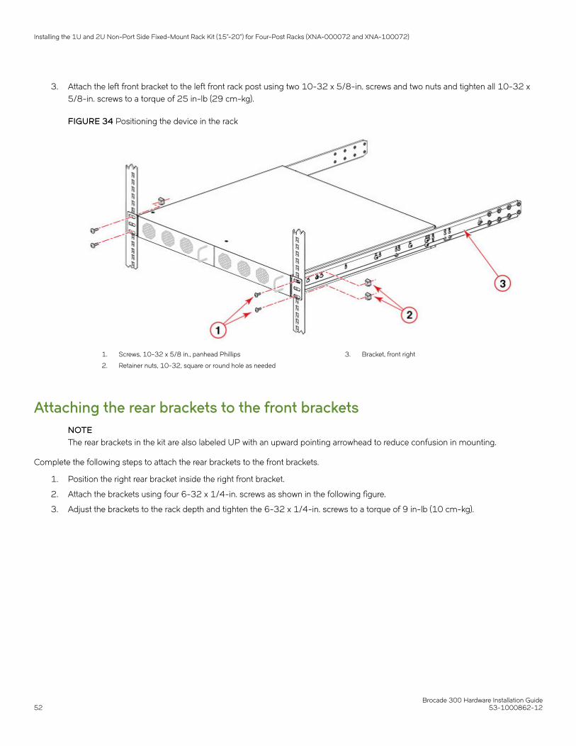
3. Attach the left front bracket to the left front rack post using two 10-32 x 5/8-in. screws and two nuts and tighten all 10-32 x5/8-in. screws to a torque of 25 in-lb (29 cm-kg).
FIGURE 34 Positioning the device in the rack
1. Screws, 10-32 x 5/8 in., panhead Phillips
2. Retainer nuts, 10-32, square or round hole as needed
3. Bracket, front right
Attaching the rear brackets to the front bracketsNOTEThe rear brackets in the kit are also labeled UP with an upward pointing arrowhead to reduce confusion in mounting.
Complete the following steps to attach the rear brackets to the front brackets.
1. Position the right rear bracket inside the right front bracket.
2. Attach the brackets using four 6-32 x 1/4-in. screws as shown in the following figure.
3. Adjust the brackets to the rack depth and tighten the 6-32 x 1/4-in. screws to a torque of 9 in-lb (10 cm-kg).
Installing the 1U and 2U Non-Port Side Fixed-Mount Rack Kit (15"-20") for Four-Post Racks (XNA-000072 and XNA-100072)
Brocade 300 Hardware Installation Guide52 53-1000862-12
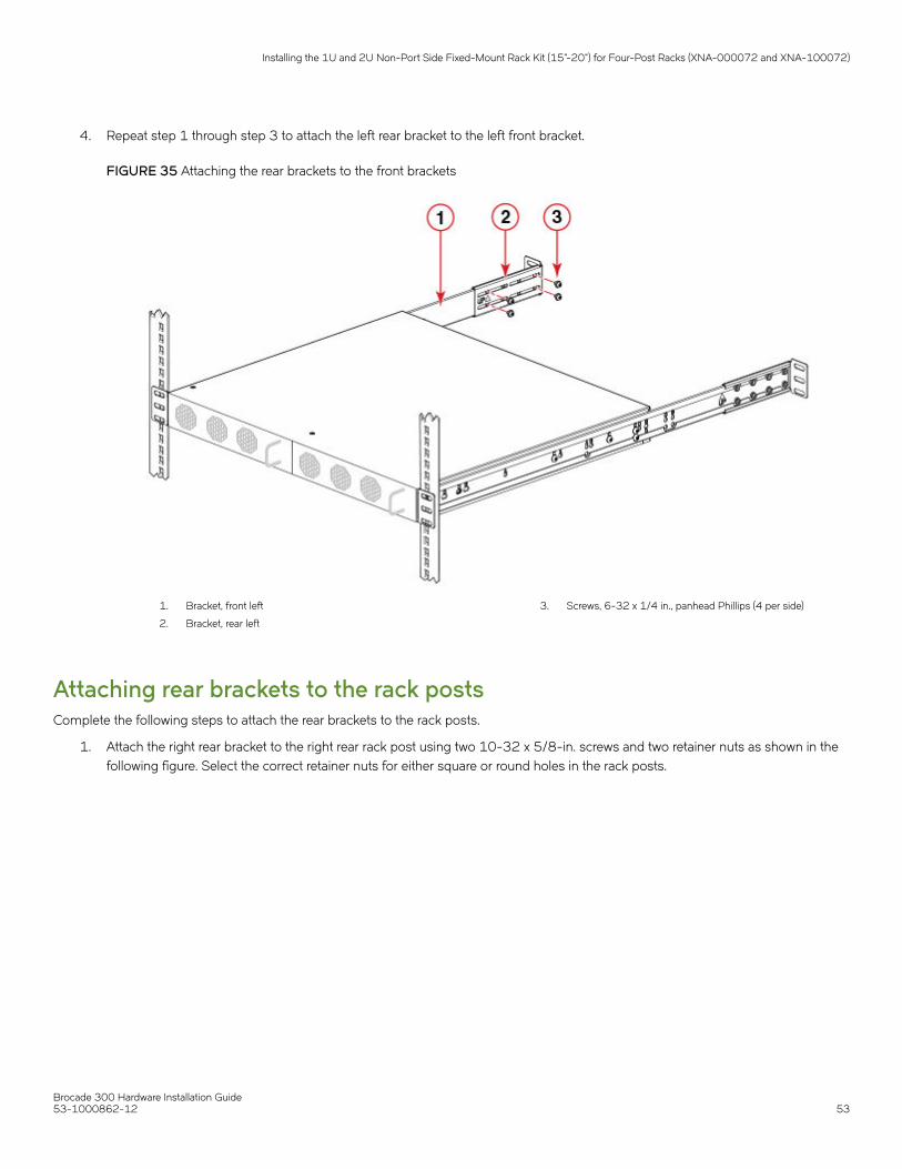
4. Repeat step 1 through step 3 to attach the left rear bracket to the left front bracket.
FIGURE 35 Attaching the rear brackets to the front brackets
1. Bracket, front left
2. Bracket, rear left
3. Screws, 6-32 x 1/4 in., panhead Phillips (4 per side)
Attaching rear brackets to the rack postsComplete the following steps to attach the rear brackets to the rack posts.
1. Attach the right rear bracket to the right rear rack post using two 10-32 x 5/8-in. screws and two retainer nuts as shown in thefollowing figure. Select the correct retainer nuts for either square or round holes in the rack posts.
Installing the 1U and 2U Non-Port Side Fixed-Mount Rack Kit (15"-20") for Four-Post Racks (XNA-000072 and XNA-100072)
Brocade 300 Hardware Installation Guide53-1000862-12 53
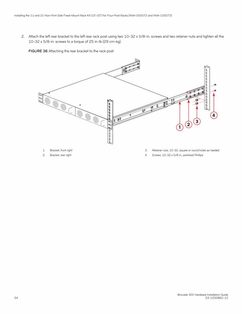
2. Attach the left rear bracket to the left rear rack post using two 10-32 x 5/8-in. screws and two retainer nuts and tighten all the10-32 x 5/8-in. screws to a torque of 25 in-lb (29 cm-kg).
FIGURE 36 Attaching the rear bracket to the rack post
1. Bracket, front right
2. Bracket, rear right
3. Retainer nuts, 10-32, square or round holes as needed
4. Screws, 10-32 x 5/8 in., panhead Phillips
Installing the 1U and 2U Non-Port Side Fixed-Mount Rack Kit (15"-20") for Four-Post Racks (XNA-000072 and XNA-100072)
Brocade 300 Hardware Installation Guide54 53-1000862-12

Initial Setup and Verification• Items required for initial setup...................................................................................................................................................................... 55• Providing power to the switch.......................................................................................................................................................................55• Creating a serial connection.......................................................................................................................................................................... 56• Setting the switch IP address........................................................................................................................................................................56• Date and time settings.....................................................................................................................................................................................57
Once you have set up the Brocade 300 in a rack or as a standalone switch, it is time to give it power and a basic configuration. If you aregoing to use the Brocade 300 in a single-switch setup, you can use EZSwitchSetup to complete the basic configuration.
Go to the my.brocade.com website to download the EZSwitchSetup software and instructions.
If you do not want to use EZSwitch Setup, follow the instructions in the rest of this section.
Items required for initial setupThe following items are required for installing and connecting the Brocade 300 for use in a network and fabric:
• Workstation with an installed terminal emulator, such as HyperTerminal
• Unused IP address and corresponding subnet mask and gateway address
• Serial cable (provided)
• Ethernet cable
• SFPs and compatible cables, as required
• Access to an FTP server for backing up the switch configuration (optional)
Providing power to the switchPerform the following steps to provide power to the switch.
1. Connect the power cord to the power receptacle on the port side of the Brocade 300, and then to the power source. Ensure thatthe cord has a minimum service loop of 15.24 cm (6 inches) available and is routed to avoid stress.
The Brocade 300 does not have an on/off switch. This means that power is supplied to the Brocade 300 as soon as youconnect it to an AC power source.
The status LEDs display amber until Power On Self Test (POST) is complete, and then change to green. The switch usuallyrequires from 1 to 3 minutes to boot and complete POST.
2. After POST is complete, verify that the switch power and status LEDs on the left of the port side of the switch are green.
Brocade 300 Hardware Installation Guide53-1000862-12 55

Creating a serial connectionYou will perform all basic configuration tasks in this guide using a serial connection. Complete the following steps to create a serialconnection.
1. Connect the serial cable to the serial port on the switch and to an RS-232 serial port on the workstation.
If the serial port on the workstation is RJ-45 instead of RS-232, remove the adapter on the end of the serial cable and insertthe exposed RJ-45 connector into the RJ-45 serial port on the workstation.
2. Open a terminal emulator application (such as HyperTerminal on a PC, or TERM, TIP, or Kermit in a UNIX environment), andconfigure the application as follows:
• In a Windows environment:
Parameter Value
Bits per second 9600
Data bits 8
Parity None
Stop bits 1
Flow control None
NOTEFlow control is not supported on the serial connection when attached to a remote terminal and must be disabledon the customer-side remote terminal server in addition to the host-side clients.
• In a UNIX environment, enter the following string at the prompt:
tip /dev/ttyb -9600.
If ttyb is already in use, use ttya instead and enter the following string at the prompt:
tip /dev/ttya -9600
Setting the switch IP addressYou can configure the Brocade 300 with a static IP address, or you can use a DHCP (Dynamic Host Configuration Protocol) server to setthe IP address of the switch. DHCP is enabled by default. The Brocade 300 supports both IPv4 and IPv6.
Using DHCP to set the IP addressWhen using DHCP, the Brocade 300 obtains its IP address, subnet mask, and default gateway address from the DHCP server. TheDHCP client can only connect to a DHCP server that is on the same subnet as the switch. If your DHCP server is not on the samesubnet as the Brocade 300, use a static IP address.
Setting a static IP address1. Log into the switch using the default password, which is password.
Creating a serial connection
Brocade 300 Hardware Installation Guide56 53-1000862-12

2. Use the ipaddrset command to set the Ethernet IP address.
If you are going to use an IPv4 IP address, enter the IP address in dotted decimal notation as prompted.
Ethernet IP Address: [192.168.74.102]
If you are going to use an IPv6 address, enter the network information in semicolon-separated notation as prompted.
switch:admin> ipaddrset -ipv6 --add 1080::8:800:200C:417A/64IP address is being changed...Done.
3. Complete the rest of the network information as prompted.
Ethernet Subnetmask: [255.255.255.0]Ethernet IP Address: [192.168.74.102]Ethernet Subnetmask: [255.255.255.0]
4. Enter off to Disable DHCP when prompted.
DHCP [OFF]: off
Date and time settingsThe Brocade 300 maintains the current date and time inside a battery-backed real-time clock (RTC) circuit. Date and time are used forlogging events. Switch operation does not depend on the date and time; a Brocade 300 with an incorrect date and time value stillfunctions properly. However, because the date and time are used for logging, error detection, and troubleshooting, you should set themcorrectly.
Time zonesYou can set the time zone for the switch by name. You can also set country, city or time zone parameters.
If the time zone is not set with the new options, the switch retains the offset time zone settings. The tsTimeZone command includes anoption to revert to the prior time zone format. For more information about the --old option, see the Brocade Fabric OS CommandReference.
You can set the time zone for a switch using the tsTimeZone command. The tsTimeZone command allows you to perform the followingtasks:
• Display all of the time zones supported in the firmware
• Set the time zone based on a country and city combination or based on a time zone ID such as PST
The time zone setting has the following characteristics:
• You can view the time zone settings. However, only those with administrative permissions can set the time zones.
• The tsTimeZone setting automatically adjusts for Daylight Savings Time.
• Changing the time zone on a switch updates the local time zone setup and is reflected in local time calculations.
• By default, all switches are in the GMT time zone (0,0). If all switches in a fabric are in one time zone, it is possible for you tokeep the time zone setup at the default setting.
• System services that have already started will reflect the time zone changes only after the next reboot.
• Time zone settings persist across failover for high availability.
Date and time settings
Brocade 300 Hardware Installation Guide53-1000862-12 57

Local time synchronizationYou can synchronize the local time of the principal or primary fabric configuration server (FCS) switch to a maximum of eight externalnetwork time protocol (NTP) servers. To keep the time in your SAN current, it is recommended that the principal or primary FCS switchhas its time synchronized with at least one external NTP server. The other switches in the fabric will automatically take their time from theprincipal or primary FCS switch.
All switches in the fabric maintain the current clock server value in non-volatile memory. By default, this value is the local clock server<LOCL> of the principal or primary FCS switch. Changes to the clock server value on the principal or primary FCS switch are propagatedto all switches in the fabric.
When a new switch enters the fabric, the time server daemon of the principal or primary FCS switch sends out the addresses of allexisting clock servers and the time to the new switch. If a switch with v5.3.0 or later has entered the fabric it will be able to store the listand the active servers; pre-5.3.0 Fabric OS switches will ignore the new list parameter in the payload and will update only the activeserver address.
If the active NTP server configured is IPv6, then distributing the same in the fabric will not be possible to switches earlier than v5.3.0because IPv6 is supported for Fabric OS version 5.3.0 and later. The default value LOCL will be distributed to pre-5.3.0 switches.
The tsClockServer command accepts multiple server addresses in either IPv4, IPv6, or DNS name formats. When multiple NTP serveraddresses are passed, tsclockserver sets the first obtainable address as the active NTP server. The rest are stored as backup servers thatcan take over if the active NTP server fails. The principal or primary FCS switch synchronizes its time with the NTP server every 64seconds.
Setting the date1. Log into the switch using the default password, which is password.
2. Enter the date command, using the following syntax:
date "mmddHHMMyy"
The values are:
• mm is the month; valid values are 01 through 12.
• dd is the date; valid values are 01 through 31.
• HH is the hour; valid values are 00 through 23.
• MM is minutes; valid values are 00 through 59.
• yy is the year; valid values are 00 through 99 (values greater than 69 are interpreted as 1970 through 1999, and valuesless than 70 are interpreted as 2000-2069).
switch:admin> dateFri Sep 29 17:01:48 UTC 2007switch:admin> date "0927123007"Thu Sep 27 12:30:00 UTC 2007switch:admin>
Setting time zonesYou must perform the procedure on all switches for which the time zone must be set. However, you only need to set the time zone onceon each switch, because the value is written to nonvolatile memory.
Use one of the two following procedures to set the time zone.
Date and time settings
Brocade 300 Hardware Installation Guide58 53-1000862-12

The following procedure describes how to set the current time zone using timezone_fmt mode to Central Standard time.
1. Log into the switch using the default password, which is password.
2. Enter the tsTimeZone command as follows:
switch:admin> tstimezone [--interactive ]/ [,timezone_fmt]
Use timezone_fmt to set the time zone by Country/City or by time zone ID, such as PST.
The following example shows how to change the time zone to US/Central.
switch:admin> tstimezoneTime Zone : US/Pacificswitch:admin> tstimezone US/Centralswitch:admin> tstimezoneTime Zone : US/Central
The following procedure describes how to set the current time zone using interactive mode to Pacific Standard Time.
1. Type the tsTimeZone command as follows:
switch:admin> tstimezone --interactive
2. You are prompted to select a general location.
Please identify a location so that time zone rules can be set correctly.
3. Enter the appropriate number or Ctrl-D to quit.
4. At the prompt, select a country location.
5. At the prompt, enter the appropriate number to specify the time zone region or Ctrl-D to quit.
Setting time zones interactivelyThe following procedure describes how to set the current time zone using interactive mode to Pacific Standard Time.
1. Type the tsTimeZone command as follows:
switch:admin> tstimezone --interactive
2. You are prompted to select a general location.
Please identify a location so that time zone rules can be set correctly.
3. Enter the appropriate number or Ctrl-D to quit.
4. At the prompt, select a country location.
5. At the prompt, enter the appropriate number to specify the time zone region or Ctrl-D to quit.
Synchronizing local time using NTPPerform the following steps to synchronize the local time using NTP.
1. Log into the switch using the default password, which is password.
Date and time settings
Brocade 300 Hardware Installation Guide53-1000862-12 59

2. Enter the tsClockServer command:
switch:admin> tsclockserver "<ntp1;ntp2>"
where ntp1 is the IP address or DNS name of the first NTP server, which the switch must be able to access. The second ntp2 isthe second NTP server and is optional. The operand "<ntp1;ntp2>" is optional; by default, this value is LOCL, which uses thelocal clock of the principal or primary switch as the clock server.
switch:admin> tsclockserverLOCLswitch:admin> tsclockserver "132.163.135.131" switch:admin> tsclockserver132.163.135.131switch:admin>
The following example shows how to set up more than one NTP server using a DNS name:
switch:admin> tsclockserver "10.32.170.1;10.32.170.2;ntp.localdomain.net"Updating Clock Server configuration...done.Updated with the NTP serversChanges to the clock server value on the principal or primary FCS switch are propagated to all switches in the fabric.
Date and time settings
Brocade 300 Hardware Installation Guide60 53-1000862-12
Monitoring the Device• Powering the Brocade 300 on and off.....................................................................................................................................................61• Interpreting LED activity................................................................................................................................................................................. 61• POST and boot specifications..................................................................................................................................................................... 63• Interpreting POST results...............................................................................................................................................................................64• Maintaining the Brocade 300...................................................................................................................................................................... 64
Powering the Brocade 300 on and offTo power on the Brocade 300, connect the power cable to the AC receptacle on the switch and to a power source. The switch runsPOST by default each time it is powered on, reset, or rebooted, and requires a up to three minutes to run.
To end the flow of power to the Brocade 300, remove the power cord from the power source.
DANGERDisconnect the power cord from all power sources to completely remove power from the device.
Interpreting LED activitySystem activity and status can be determined through the activity of the LEDs on the switch. There are three possible LED states: nolight, a steady light, and a flashing light. The steady lights and flashing lights can be green or amber.
The LEDs flash either of these colors during boot, POST, or other diagnostic tests. This is normal and does not indicate a problem unlessthe LEDs do not indicate a healthy state after all boot processes and diagnostic tests are complete.
Brocade 300 LEDs• One system status LED (above) on the left side
• One power status LED (below) on the left side
• Two Ethernet port status LEDs, one for speed and one for link status
• 24 port status LEDs, one for each port, located above the ports
LED locationsAll Brocade 300 LEDs are located on the port side.
Brocade 300 Hardware Installation Guide53-1000862-12 61

FIGURE 37 Detailed View, Brocade 300 LEDs
A. System status LED (green/amber)
B. System power LED (green)
C. Link status LED
D. Link speed LED
E. Port status LED for port 3
F. Port status LED for port 7
LED patternsThe following table summarizes the state of the Brocade 300 LEDs as well as recommended user responses.
TABLE 3 Brocade 300 LED Patterns During Normal Operation
LED Name LED Color Status of Hardware Recommended Action
Power Status No light System is off or there is an internalpower supply failure.
Verify the system is on. If thesystem is on, the unit is faulty.
Contact Technical Support.
Steady green System is on and power suppliesare functioning properly.
No action required.
System Status No light System is off, boot is not complete,or boot failed.
Verify the system is on and hascompleted booting.
Steady green System is on and power suppliesare functioning properly.
No action required.
Steady amber (for more than fiveseconds)
Boot failed, the system is faulty. Perform the following steps:
Connect a serial cable to thesystem.
Reboot the system.
Check the failure indicated on thesystem console.
Interpreting LED activity
Brocade 300 Hardware Installation Guide62 53-1000862-12

TABLE 3 Brocade 300 LED Patterns During Normal Operation (continued)
LED Name LED Color Status of Hardware Recommended Action
Contact Technical Support.
Flashing amber/green Attention is required. A number ofvariables can cause this statusincluding a single power supplyfailure, a fan failure, or one or moreenvironmental ranges hasexceeded.
Check the management interfaceand the error log for details on thecause of status.
Contact Technical Support ifrequired.
Ethernet Speed No light Port speed is 10 Mbps. No action required.
Steady green Port speed is 100 Mbps. No action required.
Ethernet Link No light There is no link. Verify the Ethernet cable isconnected correctly.
Steady amber There is a link. No action required.
Flickering amber There is link activity (traffic). No action required.
Port Status No light No signal or light carrier (media orcable) detected.
Check transceiver and cable.
Slow flashing green (flashing intwo-second intervals)
Port is online but segmentedbecause of a loopback cable orincompatible switch connection.
No action required.
Fast flashing green (flashing in half-second intervals)
Port is online and an internalloopback diagnostic test is running.
No action required.
Flickering green (steady withrandom flashes)
Port is online and frames areflowing through the port.
No action required.
Steady green Port is online (connected to externaldevice) but has no traffic.
No action required.
Slow flashing amber (flashing intwo-second intervals)
Port is disabled (because ofdiagnostics or the portDisablecommand).
Verify the diagnostic tests are notrunning. Reenable the port usingthe portEnable command.
Fast flashing amber (flashing inhalf-second intervals)
Port is faulty. Check the management interfaceand the error log for details on thecause of status.
Contact Technical Support ifrequired.
Steady amber (for more than fiveseconds)
Port is receiving light or signalcarrier at 4 Gbps; but is not yetonline.
No action required.
POST and boot specificationsWhen the switch is turned on or rebooted, the switch performs POST (power on, self test). Total boot time with POST can be severalminutes. POST can be omitted after subsequent reboots by using the fastboot command or entering the diagDisablePost command topersistently disable POST.
For more information about these commands, refer to the Fabric OS Command Reference Manual .
POST and boot specifications
Brocade 300 Hardware Installation Guide53-1000862-12 63

POSTThe success or failure results of the diagnostic tests that run during POST can be monitored through the error log or the command lineinterface.
POST includes the following steps:
1. Preliminary POST diagnostics are run.
2. Operating system is initialized.
3. Hardware is initialized.
4. Diagnostic tests are run on several functions, including circuitry, port functionality, memory, statistics counters, and serialization.
BootIn addition to POST, boot includes the following steps after POST is complete:
1. Universal port configuration is performed.
2. Links are initialized.
3. Fabric is analyzed, and if any ports are connected to other switches, the switch participates in a fabric configuration.
4. Switch obtains a domain ID and assigns port addresses.
5. Unicast routing tables are constructed.
6. Normal port operation is enabled.
Interpreting POST resultsPOST is a system check that is performed each time the switch is powered on, rebooted, or reset. During POST, the LEDs flash eitheramber or green. Any errors that occur during POST are listed in the error log.
To determine that POST completed successfully and whether or not any errors were detected:
1. Verify that the switch LEDs indicate that all components are healthy.
See the LED patterns section for descriptions and interpretations of LED patterns. If one or more LEDs do not display a healthystate, verify that the LEDs on the switch are not set to "beacon" by entering the switchShow command to detect if beaconing isactive.
2. Verify that the switch prompt displays on the terminal of a computer workstation connected to the switch.
If there is no switch prompt when POST completes, press Enter . If the switch prompt still does not display, try opening a Telnetsession or accessing through another management tool. If this is not successful, the switch did not successfully completePOST; contact your switch supplier for repair.
3. Review the switch system log for errors. Any errors detected during POST are written to the system log, accessible through theerrShow command.
For information about all referenced commands, and on accessing the error log, refer to the Fabric OS Administrator’s Guide .For information about error messages, refer to the Fabric OS Message Reference Manual .
Maintaining the Brocade 300The Brocade 300 does not require any regular physical maintenance; it was designed to minimize the chance of failure.
Interpreting POST results
Brocade 300 Hardware Installation Guide64 53-1000862-12

Ensure that the environmental conditions, described in Environmental considerations on page 15 are met. This helps prevent failure ofthe switch due to distress or abuse.
Installing an SFPThe Brocade 300 supports only Brocade-branded SFPs. If you use an unqualified SFP, the switchShow command output shows theport in a Mod_Inv state. Fabric OS also logs the issue in the system error log.
Follow these instructions to install an SFP.
1. Making sure that the bail (wire handle) is in the unlocked position, place the SFP in the correctly oriented position on the port asshown in the following figure.
NOTEFor current information on qualified transceivers supported by this device, refer to the Brocade Fibre ChannelTransceiver Platform Support Matrix and Brocade Transceiver Module Resources on www.brocade.com.
NOTEThe device supports only Brocade-qualified transceivers. If you use an unqualified transceiver, the switchshowcommand output shows the port in a Mod_Inv state. Fabric OS also logs the issue in the system error log.
Maintaining the Brocade 300
Brocade 300 Hardware Installation Guide53-1000862-12 65
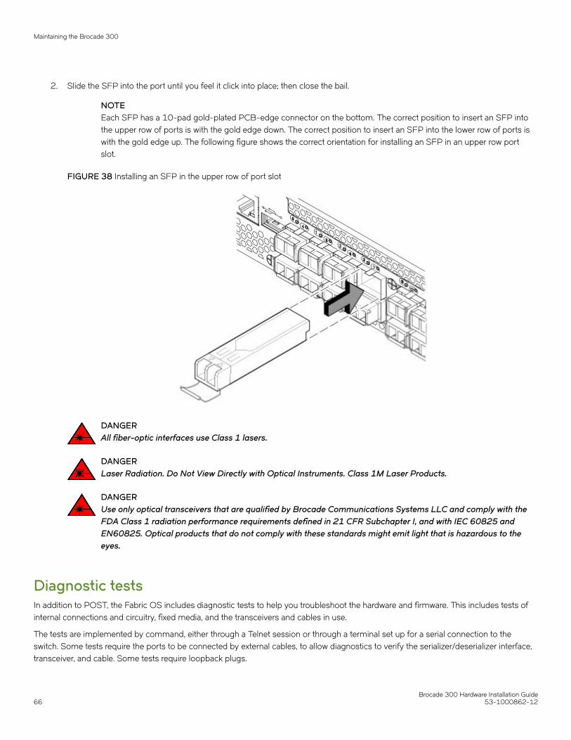
2. Slide the SFP into the port until you feel it click into place; then close the bail.
NOTEEach SFP has a 10-pad gold-plated PCB-edge connector on the bottom. The correct position to insert an SFP intothe upper row of ports is with the gold edge down. The correct position to insert an SFP into the lower row of ports iswith the gold edge up. The following figure shows the correct orientation for installing an SFP in an upper row portslot.
FIGURE 38 Installing an SFP in the upper row of port slot
DANGERAll fiber-optic interfaces use Class 1 lasers.
DANGERLaser Radiation. Do Not View Directly with Optical Instruments. Class 1M Laser Products.
DANGERUse only optical transceivers that are qualified by Brocade Communications Systems LLC and comply with theFDA Class 1 radiation performance requirements defined in 21 CFR Subchapter I, and with IEC 60825 andEN60825. Optical products that do not comply with these standards might emit light that is hazardous to theeyes.
Diagnostic testsIn addition to POST, the Fabric OS includes diagnostic tests to help you troubleshoot the hardware and firmware. This includes tests ofinternal connections and circuitry, fixed media, and the transceivers and cables in use.
The tests are implemented by command, either through a Telnet session or through a terminal set up for a serial connection to theswitch. Some tests require the ports to be connected by external cables, to allow diagnostics to verify the serializer/deserializer interface,transceiver, and cable. Some tests require loopback plugs.
Maintaining the Brocade 300
Brocade 300 Hardware Installation Guide66 53-1000862-12

All diagnostic tests are run at link speeds of 1, 2, 4, and 8 Gbps, depending on the speed of the link being tested.
NOTEDiagnostic tests can temporarily lock the transmit and receive speed of the links during diagnostic testing.
For information about specific diagnostic tests, refer to the Fabric OS Troubleshooting and Diagnostics Guide .
Field Replaceable Units (FRUs)In the Brocade 300, the only parts that are field replaceable are the SFPs. The entire switch is a FRU.
The fan units and power supply are not field replaceable in this switch.
Maintaining the Brocade 300
Brocade 300 Hardware Installation Guide53-1000862-12 67

Brocade 300 Hardware Installation Guide68 53-1000862-12

Brocade 300 Technical SpecificationsThe Brocade 300 SAN Switch is a cost-effective and highly-scalable 1, 2, 4, or 8 Gbps switch, designed for small to mid-sizedbusinesses. The Brocade 300 SAN Switch is a dual purpose device that you can use either as a full-functioned switch or as an N_PortID Virtualization (NPIV) access gateway. When functioning as an access gateway, the Brocade 300 SAN Switch provides a singleplatform for all SAN connectivity.
System specificationsSystem component Description
Enclosure 1U, 19-inch EIA-compliant
Power inlet C13; power from port side
Power supplies Single, fixed power supply
Fans Three built-in fans
Cooling Non-port to port side airflow
System architecture Nonblocking shared memory switch
System processors Power PC 440EPx, 667 MHz CPU
Fibre ChannelSystem component Description
Fibre Channel ports Switch mode (default): 8-, 16-, and 24-port configurations (8-port increments through Ports on Demand [PoD]licenses); E, F, M, and FL_Ports
Brocade Access Gateway default port mapping: 16 F_Ports, 8 N_Ports
ANSI Fibre Channel protocol Fibre Channel Physical and Signaling Interface standard (FC-PH)
Modes of operation Fibre Channel Class 2, Class 3, Class F
Fabric initialization Complies with FC-SW-2 6.6
FCIP (IP over Fibre Channel) Complies with FC-IP 2.3 of FCA profile
EthernetSystem component Description
Ethernet management port RJ-45
LEDsSystem component Description
Switch status and management One system status LED (above) on the left side
Brocade 300 Hardware Installation Guide53-1000862-12 69

System component Description
One power status LED (below) on the left side
Two Ethernet port status LEDs, one for speed and one for link status
24 port status LEDs, one for each port, located above the ports
OtherSystem component Description
Serial cable RJ-45 connector cable
RJ-45 connector 10/100 Ethernet management port; in-band over Fibre Channel; serial port (RJ-45)
Weight and physical dimensionsModel Height Width Depth Weight
Brocade 300 SAN Switch 4.29 cm
1.69 inches
42.88 cm
16.88 inches
30.66 cm
12.07 inches
4.2 kg
9.30 lb
Environmental requirementsCondition Operational Non-operational
Ambient temperature 0°C to 40°C (32°F to 104°F) -25°C to 70°C (-13°F to 158°F)
Relative humidity (non-condensing)
10% to 85% at 40°C (104°F), with maximum gradient of10% per hour
10% to 90% at 70°C (158°F)
Altitude (above sea level) 0 to 2000 m (0 to 6,600 feet) 0 to 12000 m (39,370 feet)
Shock 20 G, 6 ms, half-sine wave 33 G, 11 ms, half-sine wave, 3/eg Axis
Vibration 0.5 G sine, 0.4 gms random, 5-500 Hz 2.0 G sine, 1.1 gms random, 5-500 Hz
Airflow Maximum: 39.1 cmh (23 cfm)
Nominal: 30.6 cmh (18 cfm)
N/A
Heat dissipation 195 BTU/hr N/A
Operating noise 46.7 dB N/A
Power supply specifications (per PSU)Power supply model Maximum output
power rating (DC)Input voltage Input line frequency Maximum input
currentMaximum inrushcurrent
Not availableseparately
75 W 100 - 240 VAC(nominal)
90 - 264 VAC (range)
50/60 Hz (nominal)
47 - 63 Hz (range)
2.0 A 21.5 A
Other
Brocade 300 Hardware Installation Guide70 53-1000862-12

Power consumptionNominal 48 watts; maximum 57 watts with 24 ports at 8 Gbps.
Data port specifications (Fibre Channel)Name Number Description
Brocade 300 SANSwitch
24 Switch mode (default): 8-, 16-, and 24-port configurations (8-port increments through Ports onDemand [PoD] licenses); E_, F_, M_, and FL_Ports.
Brocade Access Gateway default port mapping: 16 F_Ports, 8 N_Ports.
Fibre Channel data transmission rangesPort speed (Gbps) Cable size (microns) Short wavelength (SWL) Long wavelength (LWL) Extended long wavelength
(ELWL)
1 50 500 m (1,640 ft) (OM2)
860 m (2,821 ft) (OM3)
N/A N/A
62.5 300 m (984 ft) N/A N/A
9 N/A 10 km (6.2 miles) 40 km (24.8 miles)
2 50 300 m (984 ft) (OM2)
500 m (1,640 ft) (OM3)
N/A N/A
62.5 150 m (492 ft) N/A N/A
9 N/A N/A 40 km (24.8 miles)
4 50 150 m (492 ft) (OM2)
380 m (1,246 ft) (OM3)
N/A N/A
62.5 70 m (230 ft) N/A N/A
9 N/A 10 km (6.2 miles) N/A
8 50 50 m (164 ft) (OM2)
150 m (492 ft) (OM3)
N/A N/A
62.5 21 m (69 ft) N/A N/A
9 N/A 10 km (6.2 miles) N/A
Serial port specifications (pinout RJ-45)Pin Signal Description
1 Not supported N/A
2 Not supported N/A
3 UART1_RXD Receive data
4 GND Logic ground
5 GND Logic ground
Serial port specifications (pinout RJ-45)
Brocade 300 Hardware Installation Guide53-1000862-12 71

Pin Signal Description
6 UART2_TXD Transmit data
7 Not supported N/A
8 Not supported N/A
NOTEThese specifications are for connectors on Brocade platformonly.
Serial port specifications (protocol)Parameter Value
Baud 9600
Data bits 8
Stop bits 1
Parity None
Flow control None
Memory specificationsMemory Type Size
Main SDRAM 512 MB
Compact Flash 1 GB
Regulatory compliance (EMC)• FCC Part 15, Subpart B
• EN 55024
• EM 55032 (CE Mark) (Class A)
• ICES-003
• VCCI
• EN 300 386
• CNS 13438
• KN 32
• KN 35
• TCVN 7189
• EN 61000-3-2
• EN 61000-3-3
• GB 9254
• CISPR 32
Serial port specifications (protocol)
Brocade 300 Hardware Installation Guide72 53-1000862-12

• 2014/30/EU
• AS/NZS CISPR32 (Australia) (Class A)
Regulatory compliance (safety)• EN/UL 60825
• EN/UL/CSA/IEC 60950-1
• GB 4943.1
• CNS 14336-1
• 2014/35/EU
Regulatory compliance (environmental)• 2011/65/EU - Restriction of the use of certain hazardous substance in electrical and electronic equipment (EU RoHS).
• 2012/19/EU - Waste electrical and electronic equipment (EU WEEE).
• 94/62/EC - packaging and packaging waste (EU).
• 2006/66/EC - batteries and accumulators and waste batteries and accumulators (EU battery directive).
• 1907/2006 of the European Parliament and of the Council of 18 December 2006 concerning the Registration, Evaluation,Authorisation and Restriction of Chemicals (EU REACH).
• Section 1502 of the Dodd-Frank Wall Street Reform and Consumer Protection Act of 2010 - U.S. Conflict Minerals.
• 30/2011/TT-BCT - Vietnam circular.
• SJ/T 11363-2006 Requirements for Concentration Limits for Certain Hazardous Substances in EIPs (China).
• SJ/T 11364-2006 Marking for the Control of Pollution Caused by EIPs (China).
Regulatory compliance (environmental)
Brocade 300 Hardware Installation Guide53-1000862-12 73

Brocade 300 Hardware Installation Guide74 53-1000862-12

Regulatory Statements• BSMI statement (Taiwan)................................................................................................................................................................................75• Canadian requirements................................................................................................................................................................................... 75• CE statement.......................................................................................................................................................................................................75• China CCC statement...................................................................................................................................................................................... 76• China ROHS........................................................................................................................................................................................................76• FCC warning (US only).................................................................................................................................................................................... 76• KCC statement (Republic of Korea)............................................................................................................................................................77• VCCI statement.................................................................................................................................................................................................. 77• Germany................................................................................................................................................................................................................77
BSMI statement (Taiwan)
Warning:
This is Class A product. In a domestic environment this product may cause radio interference in which case the user may be required totake adequate measures.
Canadian requirementsThis Class A digital apparatus meets all requirements of the Canadian Interference-Causing Equipment Regulations, ICES-003 Class A.
Cet appareil numérique de la classe A est conforme à la norme NMB-003 du Canada.
CE statementATTENTIONThis is a Class A product. In a domestic environment, this product might cause radio interference, and the user might berequired to take corrective measures.
The standards compliance label on this device contains the CE mark which indicates that this system conforms to the provisions of thefollowing European Council directives, laws, and standards:
• Electromagnetic Compatibility (EMC) Directive 2014/30/EU
• Low Voltage Directive (LVD) 2014/35/EU
• EN 55032/EN 55024 (European Immunity Requirements)
– EN61000-3-2/JEIDA (European and Japanese Harmonics Spec)– EN61000-3-3
Brocade 300 Hardware Installation Guide53-1000862-12 75

China CCC statement
China ROHSRefer to the latest revision of the China ROHS document (P/N 53‐1000428‐xx) which ships with the product.
FCC warning (US only)This equipment has been tested and complies with the limits for a Class A computing device pursuant to Part 15 of the FCC Rules.These limits are designed to provide reasonable protection against harmful interference when the equipment is operated in a commercialenvironment.
China CCC statement
Brocade 300 Hardware Installation Guide76 53-1000862-12

This equipment generates, uses, and can radiate radio frequency energy, and if not installed and used in accordance with the instructionmanual, might cause harmful interference to radio communications. Operation of this equipment in a residential area is likely to causeharmful interference, in which case the user will be required to correct the interference at the user’s own expense.
KCC statement (Republic of Korea)
Class A device (Broadcasting Communication Device for Office Use): This device obtained EMC registration for office use (Class A), andmay be used in places other than home. Sellers and/or users need to take note of this.
VCCI statement
This is a Class A product based on the standard of the Voluntary Control Council for Interference by Information Technology Equipment(VCCI). If this equipment is used in a domestic environment, radio disturbance might arise. When such trouble occurs, the user might berequired to take corrective actions.
GermanyMachine noise information regulation - 3. GPSGV, the highest sound pressure level value is 46.7 dB(A) in accordance with EN ISO7779.
Maschinenlärminformations-Verordnung - 3. GPSGV, der höchste Schalldruckpegel beträgt 47.7 dB(A) gemäss EN ISO 7779.
Germany
Brocade 300 Hardware Installation Guide53-1000862-12 77

Brocade 300 Hardware Installation Guide78 53-1000862-12

Cautions and Danger Notices• Cautions.................................................................................................................................................................................................................79• Danger Notices...................................................................................................................................................................................................80
CautionsA Caution statement alerts you to situations that can be potentially hazardous to you or cause damage to hardware, firmware, software, ordata.
Ein Vorsichthinweis warnt Sie vor potenziellen Personengefahren oder Beschädigung der Hardware, Firmware, Software oder auch voreinem möglichen Datenverlust
Un message de mise en garde vous alerte sur des situations pouvant présenter un risque potentiel de dommages corporels ou dedommages matériels, logiciels ou de perte de données.
Un mensaje de precaución le alerta de situaciones que pueden resultar peligrosas para usted o causar daños en el hardware, el firmware,el software o los datos.
General cautionsCAUTIONDo not install the device in an environment where the operating ambient temperature might exceed 40°C (104°F).
VORSICHT Das Gerät darf nicht in einer Umgebung mit einer Umgebungsbetriebstemperatur von über 40°C (104°F) installiert werden.
MISE EN GARDE N'installez pas le dispositif dans un environnement où la température d'exploitation ambiante risque de dépasser 40°C(104°F).
PRECAUCIÓN No instale el instrumento en un entorno en el que la temperatura ambiente de operación pueda exceder los 40°C (104°F).
CAUTIONMake sure the airflow around the front, and back of the device is notrestricted.
VORSICHT Stellen Sie sicher, dass an der Vorderseite, den Seiten und an der Rückseite der Luftstrom nicht behindert wird.
MISE EN GARDE Vérifiez que rien ne restreint la circulation d'air devant, derrière et sur les côtés du dispositif et qu'elle peut se faire librement.
PRECAUCIÓN Asegúrese de que el flujo de aire en las inmediaciones de las partes anterior, laterales y posterior del instrumento no estérestringido.
CAUTIONChanges or modifications made to this device that are not expressly approved by the party responsible for compliancecould void the user's authority to operate the equipment.
VORSICHT Falls dieses Gerät verändert oder modifiziert wird, ohne die ausdrückliche Genehmigung der für die Einhaltung derAnforderungen verantwortlichen Partei einzuholen, kann dem Benutzer der weitere Betrieb des Gerätes untersagt werden.
MISE EN GARDE Les éventuelles modifications apportées à cet équipement sans avoir été expressément approuvées par la partie responsabled'en évaluer la conformité sont susceptibles d'annuler le droit de l'utilisateur à utiliser cet équipement.
PRECAUCIÓN Si se realizan cambios o modificaciones en este dispositivo sin la autorización expresa de la parte responsable delcumplimiento de las normas, la licencia del usuario para operar este equipo puede quedar anulada.
Brocade 300 Hardware Installation Guide53-1000862-12 79

CAUTIONEnsure that the airflow direction of the power supply unit matches that of the installed fan tray. The power supplies and fantrays are clearly labeled with either a green arrow with an "E", or an orange arrow with an "I."
VORSICHT Vergewissern Sie sich, dass die Luftstromrichtung des Netzteils der eingebauten Lüftereinheit entspricht. Die Netzteile undLüftereinheiten sind eindeutig mit einem grünen Pfeil und dem Buchstaben "E" oder einem orangefarbenen Pfeil mit demBuchstaben "I" gekennzeichnet.
MISE EN GARDE Veillez à ce que le sens de circulation de l'air du bloc d'alimentation corresponde à celui du tiroir de ventilation installé. Lesblocs d'alimentation et les tiroirs de ventilation sont étiquetés d'une flèche verte avec un "E " ou d'une flèche orange avec un "I ".
PRECAUCIÓN Asegúrese de que la dirección del flujo de aire de la unidad de alimentación se corresponda con la de la bandeja del ventiladorinstalada. Los dispositivos de alimentación y las bandejas del ventilador están etiquetadas claramente con una flecha verde yuna "E" o con una flecha naranja y una "I".
Electrical cautionsCAUTIONBefore plugging a cable into any port, be sure to discharge the voltage stored on the cable by touching the electricalcontacts to ground surface.
VORSICHT Bevor Sie ein Kabel in einen Anschluss einstecken, entladen Sie jegliche im Kabel vorhandene elektrische Spannung, indemSie mit den elektrischen Kontakten eine geerdete Oberfläche berühren.
MISE EN GARDE Avant de brancher un câble à un port, assurez-vous de décharger la tension du câble en reliant les contacts électriques à laterre.
PRECAUCIÓN Antes de conectar un cable en cualquier puerto, asegúrese de descargar la tensión acumulada en el cable tocando lasuperficie de conexión a tierra con los contactos eléctricos.
Danger NoticesA Danger statement indicates conditions or situations that can be potentially lethal or extremely hazardous to you. Safety labels are alsoattached directly to products to warn of these conditions or situations.
Ein Gefahrenhinweis warnt vor Bedingungen oder Situationen die tödlich sein können oder Sie extrem gefährden können.Sicherheitsetiketten sind direkt auf den jeweiligen Produkten angebracht um vor diesen Bedingungen und Situationen zu warnen.
Un énoncé de danger indique des conditions ou des situations potentiellement mortelles ou extrêmement dangereuses. Des étiquettesde sécurité sont posées directement sur le produit et vous avertissent de ces conditions ou situations.
Una advertencia de peligro indica condiciones o situaciones que pueden resultar potencialmente letales o extremadamente peligrosas.También habrá etiquetas de seguridad pegadas directamente sobre los productos para advertir de estas condiciones o situaciones.
General dangersDANGERThe procedures in this manual are for qualified service personnel.
GEFAHR Die Vorgehensweisen in diesem Handbuch sind für qualifiziertes Servicepersonal bestimmt.
DANGER Les procédures décrites dans ce manuel doivent être effectuées par un personnel de maintenance qualifié.
PELIGRO Los procedimientos de este manual deben llevarlos a cabo técnicos cualificados.
Danger Notices
Brocade 300 Hardware Installation Guide80 53-1000862-12

Electrical dangersDANGERMake sure that the power source circuits are properly grounded, then use the power cord supplied with the device toconnect it to the power source.
GEFAHR Stellen Sie sicher, dass die Stromkreise ordnungsgemäß geerdet sind. Benutzen Sie dann das mit dem Gerät gelieferteStromkabel, um es an die Srromquelle anzuschließen.
DANGER Vérifiez que les circuits de sources d'alimentation sont bien mis à la terre, puis utilisez lecordon d'alimentation fourni avec ledispositif pour le connecter à la source d'alimentation.
PELIGRO Verifique que circuitos de la fuente de corriente están conectados a tierra correctamente; luego use el cordón de potenciasuministrado con el instrumento para conectarlo a la fuente de corriente
DANGERTo avoid high voltage shock, do not open the device while the power is on.
GEFAHR Das eingeschaltete Gerät darf nicht geöffnet werden, da andernfalls das Risiko eines Stromschlags mit Hochspannungbesteht.
DANGER Afin d'éviter tout choc électrique, n'ouvrez pas l'appareil lorsqu'il est sous tension.
PELIGRO Para evitar una descarga de alto voltaje, no abra el dispositivo mientras esté encendido.
DANGERBatteries used for RTC/NVRAM backup are not located in operator-access areas. There is a risk of explosion if a batteryis replace by an incorrect type. Dispose of used components with batteries according to local ordinance and regulations.
GEFAHR Die für die RTC/NVRAM-Sicherung verwendeten Batterien, befinden sich nicht in für den Bediener zugänglichen Bereichen.Bei Ersetzen der Batterie durch einen falschen Typ besteht Explosionsgefahr. Entsorgen Sie gebrauchte Komponenten mitBatterien gemäß den lokalen Auflagen und Vorschriften.
DANGER Les batteries utilisées pour la sauvegarde RTC/NVRAM ne se trouvent pas dans des zones accessibles par l'opérateur. Il y aun risque d'explosion si une batterie est remplacée par un type de batterie incompatible. Éliminez les composants utilisés avecdes batteries conformément aux ordonnances et aux règlements locaux.
PELIGRO Las baterías usadas para respaldo de RTC/NVRAM no se encuentran en areas de acceso del operador. Existe riesgo deexplosión si una batería es remplazada por un tipo incorrecto. Deshágase de los componentes usados con las baterías segúnlas politicas y regulaciones locales.
DANGERDisconnect the power cord from all power sources to completely remove power from the device.
GEFAHR Ziehen Sie das Stromkabel aus allen Stromquellen, um sicherzustellen, dass dem Gerät kein Strom zugeführt wird.
DANGER Débranchez le cordon d'alimentation de toutes les sources d'alimentation pour couper complètement l'alimentation dudispositif.
PELIGRO Para desconectar completamente la corriente del instrumento, desconecte el cordón de corriente de todas las fuentes decorriente.
Dangers related to equipment weightDANGERMake sure the rack housing the device is adequately secured to prevent it from becoming unstable or falling over.
GEFAHR Stellen Sie sicher, dass das Gestell für die Unterbringung des Geräts auf angemessene Weise gesichert ist, so dass dasGestell oder der Schrank nicht wackeln oder umfallen kann.
Danger Notices
Brocade 300 Hardware Installation Guide53-1000862-12 81

DANGER Vérifiez que le bâti abritant le dispositif est bien fixé afin qu'il ne devienne pas instable ou qu'il ne risque pas de tomber.
PELIGRO Verifique que el bastidor que alberga el instrumento está asegurado correctamente para evitar que pueda hacerse inestable oque caiga.
Laser dangersDANGERAll fiber-optic interfaces use Class 1 lasers.
GEFAHR Alle Glasfaser-Schnittstellen verwenden Laser der Klasse 1.
DANGER Toutes les interfaces en fibre optique utilisent des lasers de classe 1.
PELIGRO Todas las interfaces de fibra óptica utilizan láser de clase 1.
DANGERLaser Radiation. Do Not View Directly with Optical Instruments. Class 1M Laser Products.
GEFAHR Laserstrahlung! Schauen Sie nicht direkt mit optischen Instrumenten in den Laserstrahl herein. Klasse 1M Laserprodukte.
DANGER Rayonnement de laser. Ne regardez pas directement avec des instruments optiques. Produits de laser de classe 1M.
PELIGRO Radiacion de Laser. No vea directamente con Instrumentos Opticos. Clase 1M de Productos de Laser.
警告 レーザ放射 光学器具で直接ビームを見ないこと クラス1 M レーザ製品
DANGERUse only optical transceivers that are qualified by Brocade Communications Systems LLC and comply with the FDAClass 1 radiation performance requirements defined in 21 CFR Subchapter I, and with IEC 60825 and EN60825. Opticalproducts that do not comply with these standards might emit light that is hazardous to the eyes.
GEFAHR Verwenden Sie nur optische Transceiver, die von Brocade Communications Systems zugelassen sind und die dieAnforderungen gemäß FDA Class 1 Radiation Performance Standards in 21 CFR, Unterkapitel I, sowie IEC 60825 undEN60825 erfüllen. Optische Produkte, die diese Normen nicht erfüllen, können Strahlen aussenden, die für das menschlicheAuge gefährlich sind.
DANGER Utilisez uniquement des émetteurs-récepteurs optiques certifiés par Brocade Communications Systems LLC et conformesaux exigences sur la puissance de rayonnement de catégorie 1 de la FDA définies au sous-chapitre 21 CFR I et à les normesIEC 60825 et EN60825. Les produits optiques non-conformes à ces normes sont susceptibles d’émettre une lumièredangereuse pour les yeux.
PELIGRO Utilice sólo transceptores ópticos aprobados por Brocade Communications Systems LLC y que cumplan con las normas IEC60825 y EN60825, y con los estándares de rendimiento Clase 1 de FDA definidos en el subcapítulo I de 21 CFR. Losproductos ópticos que no cumplan con estos estándares pueden emitir luz dañina para los ojos.
Danger Notices
Brocade 300 Hardware Installation Guide82 53-1000862-12