hl-lhc (high luminosity lhc) general overview · isabel bejar alonso -cern hl-lhc configuration,...
TRANSCRIPT

HL-LHC (High Luminosity LHC)
General Overview
Isabel Bejar Alonso - CERNHL-LHC Configuration, Quality & Resources OfficerOn behalf of the HL-LHC Project teamTOBB İkiz Kuleler, ANKARA, 14th April 2016
2
Accelerating Science and InnovationAccelerating Science and Innovation

3
The HL-LHC ProjectGoals, schedule and project structure
I. Bejar Alonso - Configuration, Quality and Resource Officer

4
Goal of High Luminosity LHC (HL-LHC) as fixed in November 2010
The main objective of HiLumi LHC Design Study is to determine a hardware configuration and a set of beam parameters that will allow the LHC to reach the following targets:
A peak luminosity of Lpeak = 5×1034 cm-2s-1 with levelling, allowing:
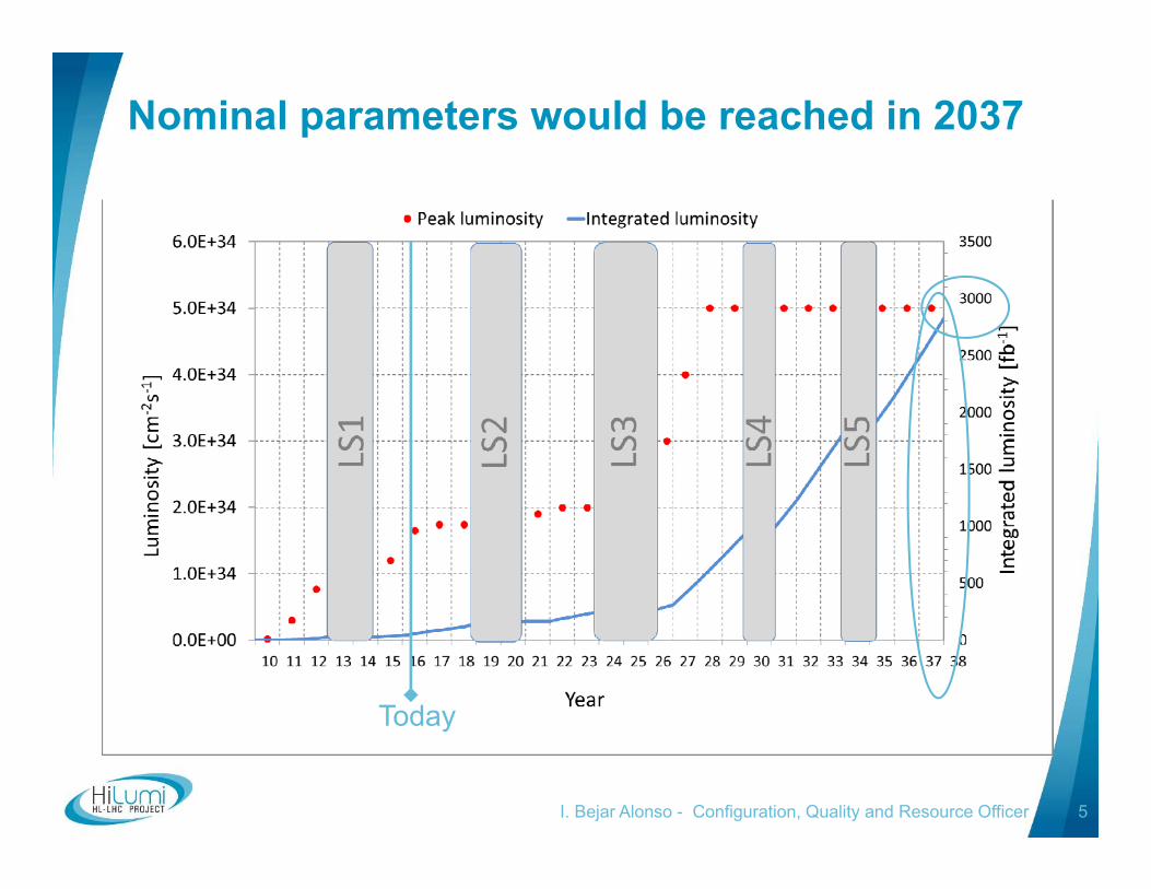
An integrated luminosity of 250 fb-1 per year, enabling the goal of Lint = 3000 fb-1 twelve years after the upgrade. This luminosity is more than ten times the luminosity reach of the first 10 years of the LHC lifetime.
From FP7 HiLumi LHC Design Study application
Concept of ultimate performance recently defined:Lult 7.5 1034 cm-2s-1 and Ultimate Integrated Lint ult 4000 fb-1
LHC should not be the limit, would Physics require more…
I. Bejar Alonso - Configuration, Quality and Resource Officer
5
Nominal parameters would be reached in 2037
Today
I. Bejar Alonso - Configuration, Quality and Resource Officer

Run I Run II Run III Run IV, V…
I. Bejar Alonso - Configuration, Quality and Resource Officer 6

HL-LHC Project Governance
I. Bejar Alonso - Configuration, Quality and Resource Officer 7

8
HL-LHC Workpackages
I. Bejar Alonso - Configuration, Quality and Resource Officer
9I. Bejar Alonso - Configuration, Quality and Resource Officer
10
The HL-LHC ProjectMain components, technical services and infrastructure

Many points around the ring
11
Surface & Underground
Underground
Main worksites

12
The largest HEP accelerator in construction
Interaction Region (ITR)Matching Section (MS)Dispersion Suppressor (DS)
ATLASATLASCMS
> 1.2 km of LHC
Complete change and new lay-out1. TAXS2. Q1-Q2-Q33. D14. All correctors5. Heavy shielding (W)
Complete change and new lay-out1. TAN2. D23. CC4. Q45. All correctors6. Q5 7. New MQ in P68. New collimators
Modifications1. In IP2: new DS
collimation in c. Cryostat
2. In IP7 new DS collimation with 11 T
Cryogenics, Protection, Interface, Vacuum, Diagnostics, Inj/Extr… extension of infrastructure
200 m

New Insertion Region lay out
LHC
HL LHC
Thick boxes are magnetic lengths -- Thin boxes are cryostats
Longer Quads; Shorter D1 (thanks to SC)Interaction region length is unchanged
ATLASCMS
ATLASCMS
13
14
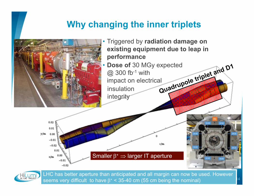
Why changing the inner triplets
Smaller larger IT aperture
• Triggered by radiation damage on existing equipment due to leap in performance
• Dose of 30 MGy expected@ 300 fb-1 withimpact on electricalinsulationintegrity
LHC has better aperture than anticipated and all margin can now be used. Howeverseems very difficult to have < 35-40 cm (55 cm being the nominal)

Working on the Inner triplet magnets
Recent Magnet Results & Plans 15
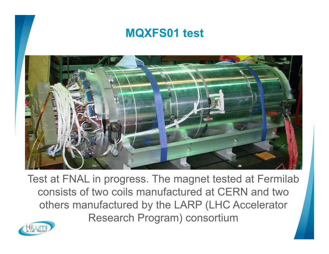
MQXFS01 test
Test at FNAL in progress. The magnet tested at Fermilabconsists of two coils manufactured at CERN and two others manufactured by the LARP (LHC Accelerator
Research Program) consortium16
17
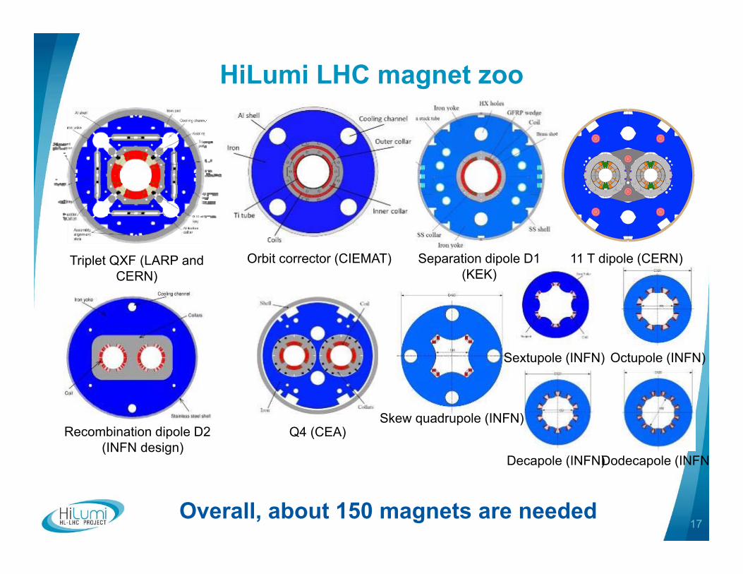
HiLumi LHC magnet zoo
Triplet QXF (LARP and CERN)
Separation dipole D1 (KEK)
Recombination dipole D2 (INFN design)
Q4 (CEA)
11 T dipole (CERN)
Sextupole (INFN)
Dodecapole (INFN
Octupole (INFN)
Decapole (INFN)
Orbit corrector (CIEMAT)
Overall, about 150 magnets are needed
Skew quadrupole (INFN)
18
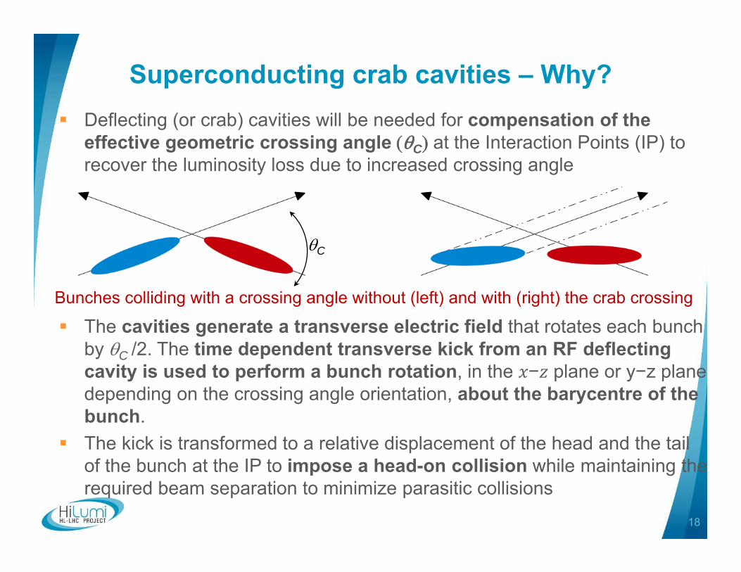
Superconducting crab cavities – Why? Deflecting (or crab) cavities will be needed for compensation of the
effective geometric crossing angle C at the Interaction Points (IP) to recover the luminosity loss due to increased crossing angle
The cavities generate a transverse electric field that rotates each bunch by C /2. The time dependent transverse kick from an RF deflecting cavity is used to perform a bunch rotation, in the − plane or y−z plane depending on the crossing angle orientation, about the barycentre of the bunch.
The kick is transformed to a relative displacement of the head and the tail of the bunch at the IP to impose a head-on collision while maintaining the required beam separation to minimize parasitic collisions
Bunches colliding with a crossing angle without (left) and with (right) the crab crossing
C

19
Crab cavities
Double Quarter Wave,Vertical Deflection
RF DipoleHorizontal Deflection
Mostly standardized interfaces and common platform
Main differences Cavity symmetry & length HOM couplers

20
SPS Cryomodule:Include 2 identical cavities
Double Quarter Wave
21
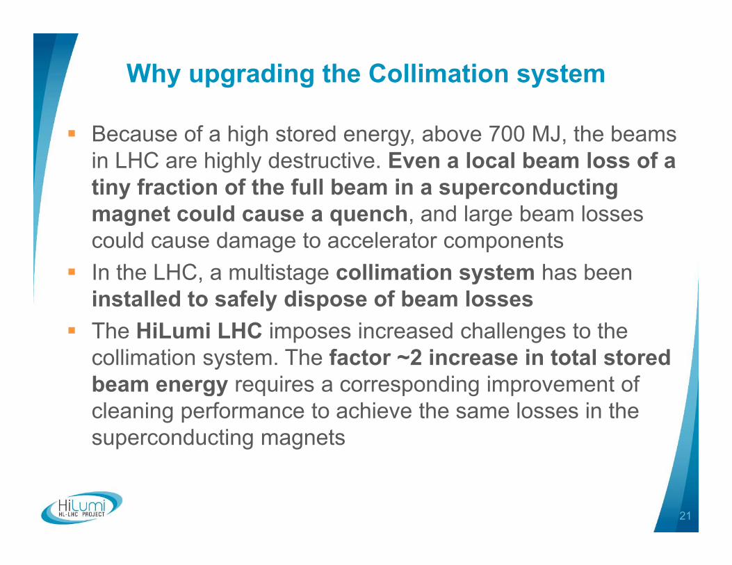
Why upgrading the Collimation system
Because of a high stored energy, above 700 MJ, the beams in LHC are highly destructive. Even a local beam loss of a tiny fraction of the full beam in a superconducting magnet could cause a quench, and large beam losses could cause damage to accelerator components
In the LHC, a multistage collimation system has been installed to safely dispose of beam losses
The HiLumi LHC imposes increased challenges to the collimation system. The factor ~2 increase in total stored beam energy requires a corresponding improvement of cleaning performance to achieve the same losses in the superconducting magnets

22
Collimation system evolving with the Run

23
TCSPM Overview Longer jaws, tapering and
vacuum tank Shorter RF fingers, upstream and
downstream flange collars Same flange-to-flange length BPM vertical buttons upstream,
on top of the horizontal BPMs for jaw positioning
Jaws
RF fingers
Vertical BPM
Horizontal BPM
Novel composite absorber
Phase II movable table
BPM cables

24
Increasing availability
2150 kA
4 pairs 150(+/- 75) kA for MS– LS3 4 pairs 100(+/-50) kA for ITR – LS3All lines in MgB2 (or HTS) tens of 6-18 kA CLs pairs in HTS
Baseline: removal to Double Decker Underground

New “DFB”: joint box
HTSMgB2
No LHe
Superconducting link concept

26
Eliminating Technical bottlenecks
IT IT
ITIT
ITITIT
IT
RF
RF

27
The 11T Dipole Two-in-One for DS
Create space in the dispersion suppressorregions of LHC, i.e. a room temperature beam vacuum sector, to install additional collimators (TCLD)Replace a standard Main Bending dipole by a pair of 11T dipoles (the 11T dipole is also called MBH)
Interconnect Space for Collimator
11 T dipole cold massBy-pass cryostat 15660 mm
∫BdL = 119.2 Tm @ Inom = 11.85 kAin series with MB with 20 % margin

28
Beam diagnostic improvement• Cryogenic BLMs & Radiation Hard Electronics
• Cryogenic BLMs• Radiation hard electronics
• Fast WireScanners• Insertion Region BPMs
• Cold directional couplers• Tungsten shielded cold directional couplers• Warm directional couplers• High precision electronics for insertion region BPMs
• Luminosity Monitors• Diagnostics for Crab Cavities• Upgrade to Synchrotron Light Monitors
• Upgrade to existing monitor• New light source• Halo diagnostics
• Beam Gas Vertex Detector• Final Implementation
• Long-Range Beam-Beam Compensator• Prototype• Final Implementation

29
And many other improvements Machine protection: improved robustness to mis-injected beams, to
kickers sparks will be required. The kicker system, collimation and TDI, isthe main shield against severe beam induced damage.
Quench Protection System of SC magnets to remake a 20 years olddesign.
Remote manipulation: the level ofactivation around 2020 requiresdevelopment of special equipment toallow replacing/servicing collimators,magnets, vacuum components etc.,according to ALARA principle. Remotemanipulation, enhanced reality andsupervision is the key to minimizingthe radiation doses sustained duringinterventions.
Vacuum …

Installation Overview for LS2 (2019-2020)
30
Cryo‐bypass+TCLD TAXNFast wire scannersBGV
TCSPM Mask for D2In‐situ a‐C coating
New Q5
Prep. workshalo diagnostic systemsHigh bandwidth pick‐ups
TCDD Mask for D1TDIS
New transp. refrigerator

Point 1 Civil Engineering underground
32
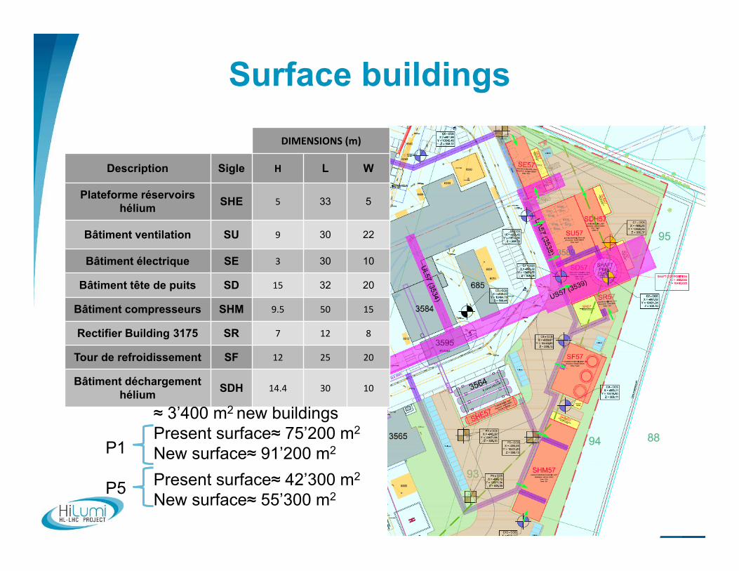
Surface buildingsDIMENSIONS (m)
Description Sigle H L W
Plateforme réservoirs hélium SHE 5 33 5
Bâtiment ventilation SU 9 30 22
Bâtiment électrique SE 3 30 10
Bâtiment tête de puits SD 15 32 20
Bâtiment compresseurs SHM 9.5 50 15
Rectifier Building 3175 SR 7 12 8
Tour de refroidissement SF 12 25 20
Bâtiment déchargement hélium SDH 14.4 30 10
≈ 3’400 m2 new buildingsPresent surface≈ 75’200 m2
New surface≈ 91’200 m2
Present surface≈ 42’300 m2
New surface≈ 55’300 m2
P1
P5

Typical view of the infrastructure needs

34
Space needed for cable traysUR:
DQSTransport
Converters
SafetyAC distribution
HV distributionSignal (transit)
IT + OF + Signal
Antenna cableSignal
AC powerdistribution
DC cablesUA:
RF
AC distribution
Signal transit
Size of cable trays (AC and signal): 600/60 mm. Distance between: 250mm
Constraints: Cable trays must be accessible for additionnal cables.

35
PM57
US57
UA57
UR57
UW57
General view
Thank you for your attention
I. Bejar Alonso - Configuration, Quality and Resource Officer 36
Special Thanks to all HL-LHC WP Leaders for their contribution

HL-LHC Project Office Organization
I. Bejar Alonso - Configuration, Quality and Resource Officer 37
38
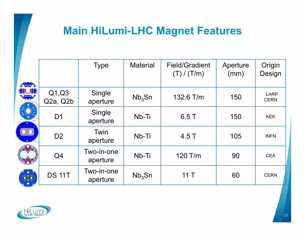
Main HiLumi-LHC Magnet Features
Type Material Field/Gradient(T) / (T/m)
Aperture(mm)
Origin Design
Q1,Q3Q2a, Q2b
Single aperture Nb3Sn 132.6 T/m 150 LARP
CERN
D1 Single aperture Nb-Ti 6.5 T 150 KEK
D2 Twin aperture Nb-Ti 4.5 T 105 INFN
Q4 Two-in-one aperture Nb-Ti 120 T/m 90 CEA
DS 11T Two-in-one aperture Nb3Sn 11 T 60 CERN