hiox aeration panel - mde.state.md.us
TRANSCRIPT

Represented by: Manufactured by:

Overview Conventional Wastewater Process Overview MBR Technology Overview Review Existing Immersed MBR Technology Overview External MBR Technology MiniMBR™ Operating Principal Design Confirmation and Testing

Conventional Treatment Plant Tertiary Filtration
Biological Treatment
Effluent
Headworks
Grit/Screenings Reject
WAS
RAS
Post Aeration
Disinfection
Influent
Secondary Clarification
Oxic Anoxic

Membrane Bioreactor (MBR)
Effluent
Post Aeration
Disinfection
WAS
Influent
Grit/Screenings
Biological Treatment
Headworks Membrane Separation
Oxic Anox

Typical MBR Advantages Liquid/solid separation does not depend on
gravity –process flexibility (high MLSS) Long SRT without long HRT – reduced excess
sludge production Small footprint
Eliminates secondary clarifiers and filters Aeration basins can be 60-80 % smaller
Ability to retrofit and upgrade existing facilities MBR can produce very high quality effluent to
meet reuse quality standards.

Membrane Basics A very thin polymeric coating or layer with engineered
pore size Applied to a backing material for strength Acts like a high tech filter Provides an absolute barrier to particles larger than the
pore size Used in a wide variety of liquid/solid separation
applications
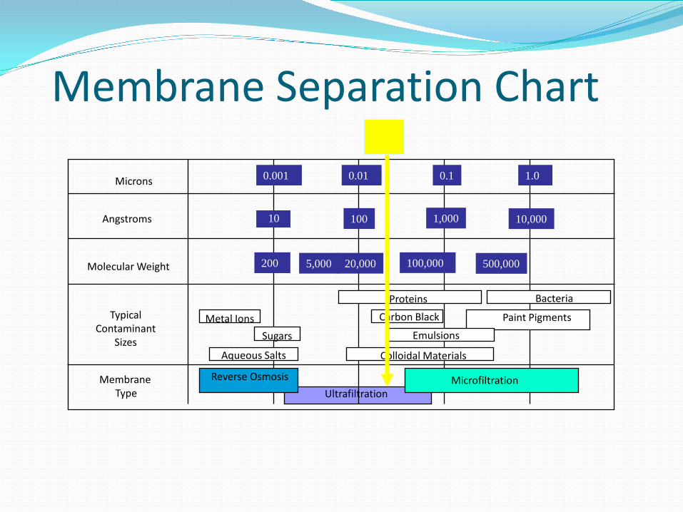
Membrane Separation Chart
Microns
Angstroms
Molecular Weight
Typical Contaminant
Sizes
Membrane Type
10 100 1,000 10,000
200 20,000 100,000 500,000 5,000
Proteins Bacteria
Paint Pigments Carbon Black
Emulsions
Colloidal Materials
Metal Ions Sugars
Aqueous Salts
Reverse Osmosis Microfiltration
0.001 0.01 0.1 1.0
Ultrafiltration

Immersed MBR Technology Hollow Fiber Membranes

Immersed MBR Technology Flat Sheet Membranes

Immersed MBR Technology No longer unproven –
widely accepted technology to produce high quality effluent
Market is growing rapidly Immersed membrane
systems (membranes submerged in MLSS) have been most widely used to date
Immersed technology driven by operating cost AIR AIR
WAS MLSS RECYCLE
PERMEATE BIOREACTOR

Immersed MBR System - Issues
In basin air scouring uses significant amounts of air and energy
Air scour adversely affects BNR process control Membrane access and maintenance issues Membrane fouling and cleaning Membrane life and “ruggedness”

Immersed MBR Technology
Access to membranes for cleaning, repair and service must be properly engineered into the system

What is an ideal SMALL MBR? Reliable, stable biological process Rugged long lasting membrane Easy access to membranes without “getting dirty” Operate at high flux and permeability for
extended periods Automatic cleaning – low operator attention Low operating cost – biological and membrane
system

External MBR Technology External MBR’s have
been around since the late 1970’s
Mostly small flows due to high capital cost and high operating cost
Cross-flow tubular membrane systems were most widely used due to ruggedness vs hollow fibers

Tubular Membrane Design Inside-out permeate flow
pattern Wide channel, non-
clogging design 5.2 mm inside dia. UF (0.03 micron nominal
pore size) PVDF membrane Strong, woven polyester
backing
MLSS
Permeate

Tubular Membrane Design Inside-out permeate flow
pattern Wide channel, non-
clogging design 5.2 mm inside dia. UF (0.03 micron nominal
pore size) PVDF membrane Strong, woven polyester
backing

Typical MBR Issues Energy consumption High capital cost Skilled operator required External membrane systems typically are cost
competitive for smaller plants, those between 5,000 gpd – 200,000 gpd
Immersed membrane systems are typically more cost competitive for plants >200,000 gpd

Until now, no MBR systems on the market were cost-effective for
plants under 5,000 gpd!

MiniMBR™ Unique membrane
arrangement lowers operating costs
Rugged and proven tubular membranes
Easy accessibility Automatic cleaning Operates on single
phase power

MiniMBR™ MicroScreen Low solids loading Low hydraulic loading Easy periodic cleaning No moving parts Easy operator access

MiniMBR™ Unique membrane
arrangement lowers operating costs

Typical Plant Layout for MiniMBR™

MiniMBR™ Typical Design MLSS = 8,000 to 12,000+ mg/l SRT – varies depending on application Ave Net Flux = 10- 30 GFD Peak Net Flux = 30-40 GFD TMP = 0.8 - 4.0 psig Automatic Backwash – 3-5 seconds every 5-10
minutes Soak Clean in Place – once per month

MiniMBR™ Typical Effluent Results BOD < 1 mg/l TSS < 1 mg/l Ortho Phosphorous < 0.1 mg/l (if required) Total Nitrogen < 3.0 mg/l (if required) >4 log virus barrier (with 0.03 micron ultrafilter) >6 log bacteria barrier Ideal pre-treatment process prior to RO, UV, GAC
or other polishing treatment steps for complete recycling of wastewater

MiniMBR™ Conclusions Tubular membrane configuration can be applied
economically to MBR applications Use of two-phase flow in vertically oriented tubular
membranes: Provides effective membrane cleaning and maintains
high flux rate and permeability Allows aeration turn-down for enhanced denitrification Significantly reduces the operating cost associated with
external membrane designs

Represented by: Manufactured by:
Questions?