highway 20 state of california...once cured the specimens were subjected to various tests to assess...
TRANSCRIPT

1
Job Report
Cold Foam In-Place Recycling Project Highway 20, State of California
Mike Marshall Wirtgen GmbH July 2001

2
Job Report
1. Brief description: 1.1 Background On the 20th January 2000, Wirtgen opened discussions with Caltrans, District 3, to explore the possibil ity of developing a Cold Foam In Place Recycling (CIFPR) project.
Caltrans had identified a section of highway 20 that was due for rehabilitation and suggested that this be a good candidate for a recycling project.
The current design strategy for the section would call for mill ing off the existing Asphalt and placing overlays and reconstructing, as follows:
18mm (OGAC 9.5mm) 90mm (DGAC 19mm type A) PRF 45mm (DGAC 19mm Type A) Lev elling course
225mm AB (Class 2) 330mm AS (Class 2) 708mm Total
The initial benefits of CIFPR were identified as:
Structural integrity: The process produces a thick 9” (225mm) bound layer.
Subgrade is not disturbed
Shorter construction window required than full reconstruction
All of the pulv erized existing AC and aggregate base would be recycled, thereby sav ing considerable “v irgin” aggregate from being hauled to the site.
In order to progress the project it was agreed that Wirtgen would employ the expertise of A.A.Loudon & Partners to carry out initial site investigations to establish if the proposed section was suitable for CIFPR and if so to determine a mix design compatible with the existing materials and the Caltrans design requirements. 1.2 Site Investigation / Mix Design Pavement investigation concerns the gathering of available information, traffic analysis and the implementation of appropriate methods of investigation in order to provide sufficient data to carry out the pavement design. These include:
i) Study of available information.
In this instance Caltrans were able to provide, as built data, traffic estimates, pavement deflection data and core samples from the existing pavement.
ii) Analysis of Design traffic.
For the section on highway 20 an anticipated Traffic index of 11 was given, this relates to a structural capacity requirement for 6.6 mill ion standard axle loads (ESAL’s)

3
Job Report
ii i) Methods of Investigation, include
Visual assessment Dynamic Cone Penetrometer survey Testpits Core Sampling Deflection Measurements Laboratory testing.
Pavement saw cut, then test pit excavated to reveal
pavement structural makeup.
Caltrans coring sections of
highway 20.

4
Job Report
Samples from the testpits were subjected to laboratory testing, to establish the quality of the materials in the existing pavement layers, and in the underlying subgrade.
Typical tests include, sieve analysis, plasticity and CBR. The results from these tests together with samples of the materials were used to formulate the mix design. Using a Wirtgen WLB10, Foamed Bitumen laboratory portions of the samples were prepared by
mixing them with various percentages of foamed bitumen to determine the optimum percentage of foamed bitumen to be added to meet the desired design requirement.
Dynamic Cone Penetrometer Survey. Using computer programs the DCP measurements are
analysed to provide, in-situ CBR, UCS and elastic moduli estimates, as well as giving an indication of
pavement balance and
structural capacity.
The WLB10 is used to:
- Determine the foaming properties of different bitumen types.
- Producing samples by injecting
foamed bitumen directly into the laboratory mixer
- The quality of mixtures to be
produced in the field can be defined exactly.
- Information on the material
properties such as load bearing capacity can be obtained before the construction work starts.

5
Job Report
The specimens were prepared using standard compaction methods The specimens were then cured Once cured the specimens were subjected to various tests to assess their engineering properties as
well as their susceptibil ity to moisture. The final mix design for the CIFPR project was determined to be:
• Recycled the existing pavement to a depth of 9” (225mm)
• Add Foamed Bitumen to the pulverized material at a rate of 2.5% by mass
• Add 1.5% water by mass to assist with the Foamed Bitumen dispersion and facil itate compaction.
1. Highway condition prior to Recycling
1.1 Traffic.
The anticipated traffic was given as a traffic index of 11, implying a structural capacity requirement of 6.6 mill ion equivalent standard axles (ESAL’s) The current Average Daily Traffic (AADT) was given as 5000 vehicles, of which 20% were heavy with an average of 1.8 ESAL’s per heavy vehicle.
1.2 Pavement failure.
Pavement failure / distress tended to be more asphalt-aging related (thermal cracking).
Start of Project looking West. Extensive crack sealing and cut outs.

6
Job Report
3. Location / Project size 3.1 Location Map
Section of Highway 20, West of Williams, within the Caltrans District 3 area.
Total length of Foam Recycling Project10.04 miles 16.2kms
Total area of Foam Recycling Project 131,480 sqm 1,419,984 sqft
Approximately half way through section
looking East. Extensive crack sealing, base failure and
shoulder failure.

7
Job Report
4. Construction Plan
The section for the CFIPR process was divided into 4 parts: Week 09th July, 5 days Foam recycle 10.04 miles, starting from the East, Recycling
the West bound lane. Week 16th July, 4 days Pave the West bound Recycled lane with 46mm Asphalt. Week 23rd July, 5 days Foam recycle 10.04 miles, starting from the East, Recycling
the East bound lane. Week 30th July, 4 days Pave the East bound Recycled lane with 46mm Asphalt.
5. Cold Foam In-Place Recycling (CFIPR) Process 5.1 Recycling Train
Two Wirtgen WR2500 Recyclers were used working in echelon.
8
Job Report
Each WR2500 recycler was coupled with: • Bitumen supply tanker, in front, bitumen heated to a temperature of 350 deg F. The supply
tanker is pushed by the WR2500 • Water cart, in rear. The Water cart is pulled by the WR2500
The lead WR2500 was fitted with an 8ft (2.5m) cutter and the following WR2500 fitted with a 10ft (3.0m) cutter. The road width varied from 21.5ft (6.6m) to 31.5ft (9.72m) therefore, it was always possible to recycle one half of the road in one pass. The Wirtgen foam spray bar system is fitted with
16 jets, it is possible to cut off jets so as not to “double dose” the recycled material with bitumen. In the picture above the lead machine is working with all 16 jets spraying to a width of 8ft (2.5m), the following machine is working to width of 4.5ft (1.4m) with 8 jets spraying. Foam spray jets can be switched on or off from the cabin to accommodate varying road widths.
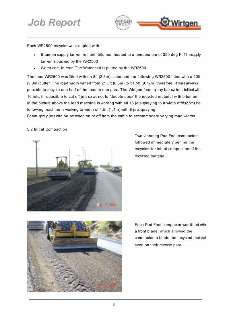
5.2 Initial Compaction
Two vibrating Pad Foot compactors followed immediately behind the recyclers for initial compaction of the
recycled material.
Each Pad Foot compactor was fitted with a front blade, which allowed the compactor to blade the recycled material
even on their reverse pass.

9
Job Report
5.3 Grading / Shaping
Following the initial compaction, a motor grader was used to cut the recycled
material to the desired levels.
Motor grader cutting recycled material level.
Followed by steel drum compactor.
Recycled material cut to finished level,
ready for final compaction and finish.

10
Job Report
5.4 Compaction
5.5 Water Two water carts were employed on the site:
1) Used to keep recycled material moist 2) Used in the surface finishing operation
The recycled material is constantly watered to keep the surface moist. The water cart makes it’s run between
traffic flow changes.
Final compaction was achieved using a plain steel single drum vibrating compactor.

11
Job Report
5.6 Final compaction / Surface Finish
5.7 Sweeper
The second water cart working with the
Pneumatic tyred Roller on surface finish.
While the recycled surface is WET, the Pneumatic Tyred Roller is used to create
a surface slush effect, which knits together the finer particles at the surface. This process locks in the larger particles
and avoids surface raveling. The resulting finish provides an excellent
smooth surface for traffic to run on.
The final operation on the recycled
lane is to sweep the edge clear of any
loose material.
12
Job Report
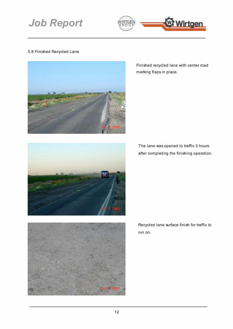
5.8 Finished Recycled Lane
Finished recycled lane with center road marking flaps in place.
The lane was opened to traffic 3 hours
after completing the finishing operation.
Recycled lane surface finish for traffic to
run on.

13
Job Report
6. Asphalt wearing course
7. Longitudinal Joint between lanes.
Monday 23rd July. The West bound lane (on right of photo) has been paved with 46mm of asphalt.
The recycling operation has started on the
East bound lane (on left of photo)
The East bound lane being recycled. The recycler cuts up to the edge of the
adjacent paved lane.
14
Job Report
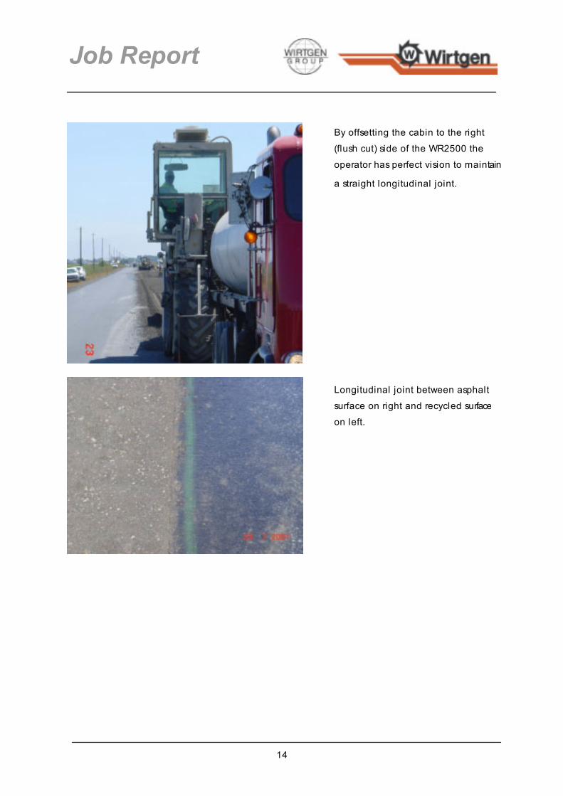
By offsetting the cabin to the right (flush cut) side of the WR2500 the operator has perfect vision to maintain
a straight longitudinal joint.
Longitudinal joint between asphalt surface on right and recycled surface on left.

15
Job Report
8. Application shots.
8.1 Recycling with traffic
View of the recycling train on the West bound lane.
This view is between traffic flow changes.
Traffic is convoyed through the work site safely.
There is no interruption to the recycling
operation and traffic delay is minimal.

16
Job Report
8.2 Sharp bend with Super Elevation
Sharp bend with 14% Super Elevation Average asphalt thickness to be recycled
9” (225mm).
First recycler enters bend, with traffic under
convoy in adjacent lane.
Both recyclers working in the bend with
traffic

17
Job Report
8.2 Deep Asphalt sections
Grading and compaction operation on
the recycled material
Finished recycled surface, after trafficking
Sections of the pavement, up to 10” + (250mm +) of asphalt.

18
Job Report
9. Before and After views
9.1 View from project start point looking West
June 2000 July 2001 Left lane Right Lane Recycled finish Asphalt finish
9” (225mm) asphalt
Varying depths of asphalt were found, ranging from 4.5” ( 114mm) to 10” (250mm)
19
Job Report
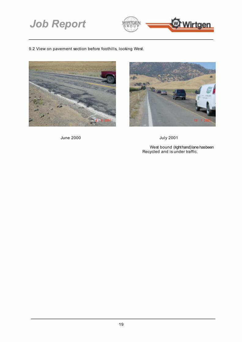
9.2 View on pavement section before foothil ls, looking West.
June 2000 July 2001 West bound (right hand) lane has been Recycled and is under traffic.

Illustrations are without obligation. Subject to technical changes. Performance data depends on operational conditions. No. 50-30 EN-07/03 © by Wirtgen GmbH 2003 Printed in Germany.
Wirtgen GmbH • Hohner Strasse 2 53578 Windhagen • Germany Phone: + 49 (0) 26 45 / 131-0 Fax: + 49 (0) 26 45 /131-242 Internet: www.wirtgen.com