higher-harmonic generation analysis in complex waveguides ... · claudio nucera and francesco lanza...
TRANSCRIPT
Hindawi Publishing CorporationMathematical Problems in EngineeringVolume 2012, Article ID 365630, 16 pagesdoi:10.1155/2012/365630
Research ArticleHigher-Harmonic Generation Analysis inComplex Waveguides via a NonlinearSemianalytical Finite Element Algorithm
Claudio Nucera and Francesco Lanza di Scalea
Department of Structural Engineering, University of California, San Diego,9500 Gilman Drive, M.C. 0085, La Jolla, CA 92093-0085, USA
Correspondence should be addressed to Claudio Nucera, [email protected]
Received 7 April 2012; Accepted 10 May 2012
Academic Editor: Ivan Bartoli
Copyright q 2012 C. Nucera and F. Lanza di Scalea. This is an open access article distributedunder the Creative Commons Attribution License, which permits unrestricted use, distribution,and reproduction in any medium, provided the original work is properly cited.
Propagation of nonlinear guided waves is a very attracting phenomenon for structural healthmonitoring applications that has received a lot of attention in the last decades. They exhibit verylarge sensitivity to structural conditions when compared to traditional approaches based on linearwave features. On the other hand, the applicability of this technology is still limited because ofthe lack of a solid understanding of the complex phenomena involved when dealing with realstructures. In fact the mathematical framework governing the nonlinear guided wave propagationbecomes extremely challenging in the case of waveguides that are complex in either materials(damping, anisotropy, heterogeneous, etc.) or geometry (multilayers, geometric periodicity, etc.).The present work focuses on the analysis of nonlinear second-harmonic generation in complexwaveguides by extending the classical Semianalytical Finite Element formulation to the nonlinearregime, and implementing it into a powerful commercial Finite Element package. Results arepresented for the following cases: a railroad track and a viscoelastic plate. For these case-studies optimum combinations of primary wave modes and resonant double-harmonic nonlinearwave modes are identified. Knowledge of such combinations is critical to the implementation ofstructural monitoring systems for these structures based on higher-harmonic wave generation.
1. Introduction
Traditional techniques in nondestructive evaluation and structural health monitoringapplications rely on measuring “linear” parameters of the waves (amplitude, speed, andphase shifts) to infer salient features of the inspected structure. Several studies, however, haveshown that “nonlinear” parameters are, in general, more sensitive to structural conditionthan linear parameters [1]. Furthermore, the use of nonlinear guided waves is extremelyattractive because guided waves combine the mentioned high sensitivity typical of nonlinearparameters with large inspection ranges [2–9].
2 Mathematical Problems in Engineering
From a mathematical standpoint, the framework behind nonlinear guided wavespropagation is relatively challenging since the Navier elastodynamic equations are furthercomplicated by stress-free conditions at the waveguide’s cross-sectional boundaries. Forthis reason, most of the previous works on elastic waves in waveguide solids consideredthe propagation to be in the linear elastic regime with the assumption of infinitesimaldeformations (coincidence between deformed and initial configurations). However, as theamplitude of the wave increases or the structure starts experiencing finite deformations (i.e.,nonlinear elasticity) or another cause of nonlinear effects is present, the nonlinearity in thestructural response becomes relevant and must be introduced in the analysis. Hence cubic(and eventually higher-order) terms in the particle displacements gradients must be includedin the elastic strain energy density expression [10, 11].
Among the manifestations of the nonlinear behavior, higher-harmonic generation isconsidered in detail in the present work. In this scenario, supposing to excite an ultrasonicwave into the waveguide structure at a fixed frequency, ω (Fundamental Frequency), thenonlinearity manifests itself in the generation of multiple harmonics of ω, for example, 2ω(second harmonic), 3ω (third harmonic), and so on. For a practical use, this nonlinearity canbe quantified via an ultrasonic nonlinear parameter, β, well documented in literature [2].
In the last thirty years, several successful applications of nonlinear guided waves havebeen discussed, spanning from assessing the fatigue damage of metals [12–14] and concrete[15], to the efficient location of internal cracks and dislocations [16–20]. The authors of thepresent paper recently exploited the features of nonlinear guided wave propagation in seven-wire steel strands and proposed a methodology to measure the stress level acting on thesestructural elements based on the theory of contact acoustic nonlinearity [21].
While several investigations pertaining to nonlinear effect in solids and secondharmonic generation were reported in the past [22, 23], most of them were limited in theirapplicability to structures with simple geometries (plates, rods, and shells) where analyticalsolutions for the primary (linear) wave field are available in literature. Very few studiestried to analyze the nonlinear wave propagation phenomena in geometrically complexwaveguides using specialized SAFE codes [24].
In the present work, the propagation of waves in nonlinear solid waveguides withcomplex geometrical and material properties is investigated theoretically and numerically.For the solution of the nonlinear boundary value problem, perturbation theory and modalexpansion are used [22]. The main novelty consists in the development of a powerfulnumerical algorithm, able to efficiently predict and explore the nonlinear wave propagationphenomena in several types of structural waveguides. It is based on the implementation ofa nonlinear semianalytical finite element formulation into a commercial multipurpose finiteelement package. Compared to the classical finite element formulation, the proposed solutionis computationally more efficient since it simply requires the finite element discretizationof the cross-section of the waveguide and assumes harmonic motion along the wavepropagation direction. Furthermore, compared to traditional spectral or waveguide elementmethod approaches, no new elements need to be developed, the full power of ready-to-use high-order shape functions (crucial for the development of the present theory) can beeasily exploited though friendly GUI, and immediate and extensive postprocessing for allthe required quantities can be developed.
The applicability of the proposed analysis is quite wide, since it can efficiently handlegeneral prismatic structures, viscoelastic waveguides with damping effects, multilayeredcomposite laminate panels, and heterogeneous systems, all cases where theoretical wavesolutions are either nonexistent or extremely difficult to determine. In addition, the proposed
Mathematical Problems in Engineering 3
approach requires simple modifications to the original commercial FEM code so that thenonlinear semianalytical formulation can be taken into account and translated to match therequired formalism. After a brief discussion on the background of the present work andthe proposed algorithm, two case studies have been analyzed in detail: a railroad trackand a viscoelastic plate. They were considered to show the potential of the algorithm inhandling complex geometry as well as viscoelastic material properties. The proposed codewas successful in identifying optimal combinations of resonant primary and secondarymodes. The knowledge of these nonlinear resonance conditions is of paramount importancefor the actual implementation of conditions assessment systems for these structures that arebased on the measurement of nonlinear ultrasonic guided waves.
2. Nonlinear Guided Waves Propagation
In the present section, a brief overview of the generalized nonlinear theory of elasticity forwave propagation involving finite deformations is presented [25]. Following [22], assumingthat the body is homogeneous, isotropic, and hyperelastic, it possesses a strain energy densityε which is an analytic function of the Green-Lagrange strain tensor Eij via its invariants; inthis scenario, the Second Piola-Kirchoff stress tensor Sij can be expressed as:
Sij = ρ0∂ε
∂Eij, (2.1)
where ρ0 is the initial density of the body.According to finite strain theory, in (2.1) we have assumed the following:
Eij =12(ui,j + uj,i + uk,iuk,j
), ui,j =
∂ui
∂xj. (2.2)
The strain energy density expression becomes
ε =12λI21 + μI2 +
13CI31 + BI1I2 +
13AI3 +O
(E4ij
), (2.3)
where I1, I2, and I3 are the first three invariants of the Green-Lagrange strain tensor definedas I1 = Eii, I2 = EijEji, and I3 = EijEjkEki; λ and μ are the Lame elastic constants andA, B, andC are the Landau-Lifshitz third-order elastic constants [26].
In (2.3), first-order material nonlinearity was introduced through A,B,C, andgeometric nonlinearity through Eij . By substituting (2.3) into (2.1), and keeping up to second-order terms in Eij , the nonlinear hyperelastic constitutive equation reads
Sij = λEkkδij + 2μEij + δij(CEkkEll + BEklElk) + 2BEkkEij +AEjkEki. (2.4)

4 Mathematical Problems in Engineering
Using (2.4) in the general momentum equation, the nonlinear boundary valueproblem governing the propagation of nonlinear elastic waves in isotropic, homogeneousand hyperelastic waveguides can be formulated as [10]:
ρ0ui − μui,kk −(λ + μ
)ul,li =
(μ +
A
4
)(ul,kkul,i + ul,kkui,l + 2ui,lkul,k)
+(λ + μ +
A
4+ B
)(ul,ikul,k + uk,lkui,l) + (λ + B)ui,kkul,l
+(A
4+ B
)(uk,lkul,i + ul,ikuk,l) + (B + 2C)uk,ikul,l.
(2.5)
Characterizing the system of (2.5) to the “guided” wave propagation case (stress-freeboundary condition), the governing equations can be recast in vector notation as:
(λ + 2μ
)∇(∇ · u) − μ∇ × (∇ × u) + f = ρ0∂2u
∂t2,
SL(u) · nr = −S(u) · nr on Γ,
(2.6)
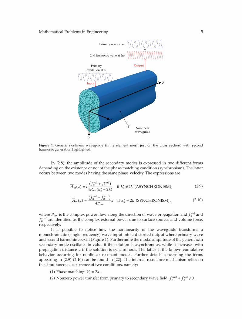
where u is the particle displacement vector, ρ0, λ and μ are defined above, f is the nonlinearterm acting as a body force, nr is the unit vector normal to the surface of the waveguide Γ,and SL and S are the linear and nonlinear parts of the second Piola-Kirchoff stress tensor,respectively. The nonlinear waveguide system is illustrated in Figure 1.
Considering higher harmonics up to the second order, the nonlinear boundary valueproblem presented in (2.6) is solved using perturbation theory. The solution of the primarywave field can be obtained analytically for simple geometries (plates, rods, shells, etc.)and numerically using the classical SAFE formulation for waveguides with generic cross-section [27]. Following [22, 28], if ω is the primary frequency that is excited into the system,the first-order nonlinear solution is calculated through modal expansion using the existingpropagating guided modes 2ω as:
v(x, y, z, t
)=
12
∞∑
m=1
Am(z)vm
(x, y
)e−i2ωt + c.c., (2.7)
where (x, y) are the cross-sectional coordinates of the waveguide, z is the lengthwisecoordinate of the waveguide, c.c. denotes complex conjugates, vm is the particle velocityvector referred to the mth mode at 2ω, and Am is the higher-order modal amplitude givenby:
Am(z) = Am(z)ei(2kz) −Am(0)eik∗nz, (2.8)
where k represents the wavenumber. The amplitude Am(z) quantifies how strong is theexcitation of the mth secondary mode in the modal expansion.
Mathematical Problems in Engineering 5
Primary wave at ω
2nd harmonic wave at 2ω
Output
Input Z
X
Y
Γ Nonlinearwaveguide
Primaryexcitation at ω
+
Figure 1: Generic nonlinear waveguide (finite element mesh just on the cross section) with secondharmonic generation highlighted.
In (2.8), the amplitude of the secondary modes is expressed in two different formsdepending on the existence or not of the phase-matching condition (synchronism). The latteroccurs between two modes having the same phase velocity. The expressions are
Am(z) = i
(fvoln + f surf
n
)
4Pmn(k∗n − 2k)
if k∗n /= 2k (ASYNCHRONISM), (2.9)
Am(z) =
(fvoln + f surf
n
)
4Pmnz if k∗
n = 2k (SYNCHRONISM), (2.10)
where Pmn is the complex power flow along the direction of wave propagation and fvoln and
f surfn are identified as the complex external power due to surface sources and volume force,
respectively.It is possible to notice how the nonlinearity of the waveguide transforms a
monochromatic (single frequency) wave input into a distorted output where primary waveand second harmonic coexist (Figure 1). Furthermore the modal amplitude of the genericmthsecondary mode oscillates in value if the solution is asynchronous, while it increases withpropagation distance z if the solution is synchronous. The latter is the known cumulativebehavior occurring for nonlinear resonant modes. Further details concerning the termsappearing in (2.9)-(2.10) can be found in [22]. The internal resonance mechanism relies onthe simultaneous occurrence of two conditions, namely:
(1) Phase matching: k∗n = 2k.
(2) Nonzero power transfer from primary to secondary wave field: f surfn + fvol
n /= 0.
6 Mathematical Problems in Engineering
Recent investigations performed by Deng et al. have analyzed the influence of anadditional requirement for the occurrence of internal resonance, namely, the group velocitymatching [29]. In this study, the authors showed analytically and experimentally that, aslong as the two aforementioned conditions (phase-matching and nonzero power transfer)are satisfied, the cumulative effect of the secondary resonant mode takes place even whenthe group velocity matching condition is not satisfied. They concluded that group velocitymatching does not represent a necessary requirement for cumulative second-harmonicgeneration. For this reason in the present work, phase-matching and power transfer onlyare considered in detail.
In nonlinear structural monitoring, the key consists of the identification of an optimalcombination of synchronous primary and secondary modes. The rest of this paper presentsa numerical tool that enables to identify these resonant conditions for various complexwaveguides, that would be extremely difficult to study by other means, and that includecases of periodic structures, damped structures, multilayered geometries and heterogeneousstructures.
3. Nonlinear Semianalytical Finite Element Algorithm
Linear SAFE formulation has shown in the past its great potential in calculating thedispersion characteristics of complex waveguides (where the analytical solution is notavailable) in a very efficient way [27, 30]. The knowledge of these curves is the starting pointfor the development of any application based on the use of guided waves. The present workfocuses on the extension of this approach to the nonlinear regime and its implementation,into a highly flexible COMSOL commercial code, of a nonlinear SAFE formulation to solvecomplex waveguides (CO.NO.SAFE Algorithm).
The implementation combines the full power of existing libraries and routines of thecommercial code with its ease of use and extremely capable postprocessing functions; henceinternal resonance conditions of structural waveguides with different level of complexity canbe conveniently analyzed via user-friendly interfaces. Furthermore, since all the nonlinearparameters involve gradients of the displacement field up to the third order, high-order finiteelements (at least cubic) need to be used in order to obtain meaningful results; this task is nottrivial to implement in general SAFE algorithms.
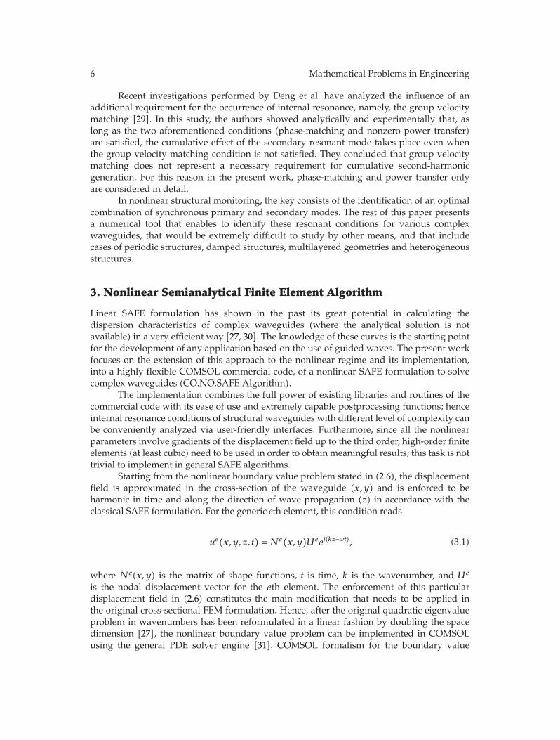
Starting from the nonlinear boundary value problem stated in (2.6), the displacementfield is approximated in the cross-section of the waveguide (x, y) and is enforced to beharmonic in time and along the direction of wave propagation (z) in accordance with theclassical SAFE formulation. For the generic eth element, this condition reads
ue(x, y, z, t)= Ne(x, y
)Ueei(kz−ωt), (3.1)
where Ne(x, y) is the matrix of shape functions, t is time, k is the wavenumber, and Ue
is the nodal displacement vector for the eth element. The enforcement of this particulardisplacement field in (2.6) constitutes the main modification that needs to be applied inthe original cross-sectional FEM formulation. Hence, after the original quadratic eigenvalueproblem in wavenumbers has been reformulated in a linear fashion by doubling the spacedimension [27], the nonlinear boundary value problem can be implemented in COMSOLusing the general PDE solver engine [31]. COMSOL formalism for the boundary value

Mathematical Problems in Engineering 7
Table 1:Material properties assumed for the railroad track analysis.
ρ (kg/m3) λ (GPa) μ (GPa) A (GPa) B (GPa) C (GPa)7932 116.25 82.754 −340 −646.667 −16.667
problem with Neumann boundary conditions (which correspond to the guided wavepropagation) is
∇ · (c∇U + αU − γ) − β · ∇U − aU + λdaU = 0, (3.2)
n · (c∇U + αU) + qU = 0, (3.3)
where n is the outward unit normal vector on the surface of the waveguide, c is the diffusioncoefficient, α is the conservative flux convection coefficient, da is a damping coefficient, β isthe convection coefficient, a is the absorption coefficient, γ is the conservative flux sourceterm, f is the source term, q is the boundary absorption term, λ is the eigenvalue and Urepresents the set of dependent variables to be determined. All these coefficients generallyadmit complex values (appropriate for viscoelastic materials) [32]. The formalism introducedin (3.2)-(3.3) is very general and can be used for a broad range of physical problems governedby a system of PDEs, once every coefficient has been conveniently characterized to theparticular physics governing the considered problem.
Once all the parameters have been defined, dispersion curves for the selectedwaveguide can be promptly calculated. Next, after a particular frequency has been selectedas primary excitation, second harmonic generation and internal resonance occurrence can beanalyzed.
In the next section, the proposed algorithm is benchmarked with two case studies ofinterest in structural engineering.
4. Applications
4.1. Railroad Track
A136RE railroad track was considered first for this study. Due to the complex geometryof the cross section, solutions for the dispersion curves and, consequently, for the higherharmonic generation analysis cannot be calculated analytically. After a preliminary studyinvolving the selection and the analysis of internal resonance conditions for several primary-secondary wave field combinations, two exemplary cases were selected as representative. Inthe first case, phase matching between primary and secondary modes is verified. However,due to the characteristic energy distribution over the rail cross-section, no power transferis present between the modes and, consequently, internal resonance does not occur; hence,the secondary modal amplitude is bound in value and oscillates with distance along thedirection of wave propagation (3.1). In the second case, instead, both required conditionsare verified and internal resonance takes place, leading to a resonant secondary wave fieldgrowing linearly with wave propagation distance.
The material properties considered are given in Table 1. The Landau-Lifshitz third-order elastic constants are detailed in [33].
8 Mathematical Problems in Engineering
Y(m
)
X (m)
0.1
0.08
0.06
0.04
0.02
0
−0.02
−0.04
−0.06
−0.08
−0.1−0.1 −0.05 0 0.05 0.1
Cubic triangularLagrange element
(a)
×103
10
9
8
7
6
5
4
3
2
1
00 20 40 60 80 100 120 140 160 180 200
Frequency (kHz)
Phas
e ve
loci
ty(m
/s)
Primary flexural head and secondary (resonant)Primary flexural web and secondary (nonresonant)
(b)
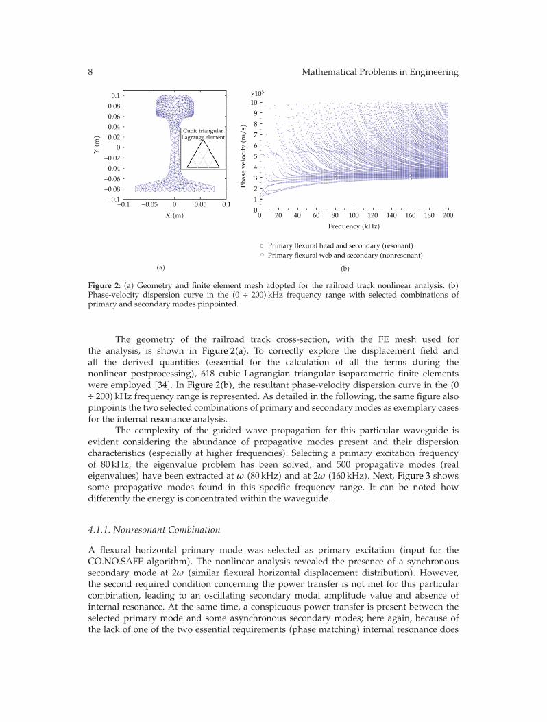
Figure 2: (a) Geometry and finite element mesh adopted for the railroad track nonlinear analysis. (b)Phase-velocity dispersion curve in the (0 ÷ 200) kHz frequency range with selected combinations ofprimary and secondary modes pinpointed.
The geometry of the railroad track cross-section, with the FE mesh used forthe analysis, is shown in Figure 2(a). To correctly explore the displacement field andall the derived quantities (essential for the calculation of all the terms during thenonlinear postprocessing), 618 cubic Lagrangian triangular isoparametric finite elementswere employed [34]. In Figure 2(b), the resultant phase-velocity dispersion curve in the (0÷ 200) kHz frequency range is represented. As detailed in the following, the same figure alsopinpoints the two selected combinations of primary and secondarymodes as exemplary casesfor the internal resonance analysis.
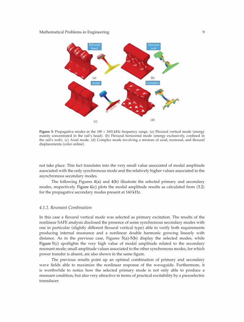
The complexity of the guided wave propagation for this particular waveguide isevident considering the abundance of propagative modes present and their dispersioncharacteristics (especially at higher frequencies). Selecting a primary excitation frequencyof 80 kHz, the eigenvalue problem has been solved, and 500 propagative modes (realeigenvalues) have been extracted at ω (80 kHz) and at 2ω (160 kHz). Next, Figure 3 showssome propagative modes found in this specific frequency range. It can be noted howdifferently the energy is concentrated within the waveguide.
4.1.1. Nonresonant Combination
A flexural horizontal primary mode was selected as primary excitation (input for theCO.NO.SAFE algorithm). The nonlinear analysis revealed the presence of a synchronoussecondary mode at 2ω (similar flexural horizontal displacement distribution). However,the second required condition concerning the power transfer is not met for this particularcombination, leading to an oscillating secondary modal amplitude value and absence ofinternal resonance. At the same time, a conspicuous power transfer is present between theselected primary mode and some asynchronous secondary modes; here again, because ofthe lack of one of the two essential requirements (phase matching) internal resonance does
Mathematical Problems in Engineering 9
(a) (b)
(c) (d)
Flexuralhead
Axial Complex
Flexuralweb
Figure 3: Propagative modes in the (80 ÷ 160) kHz frequency range. (a) Flexural vertical mode (energymainly concentrated in the rail’s head). (b) Flexural horizontal mode (energy exclusively, confined inthe rail’s web). (c) Axial mode. (d) Complex mode involving a mixture of axial, torsional, and flexuraldisplacements (color online).
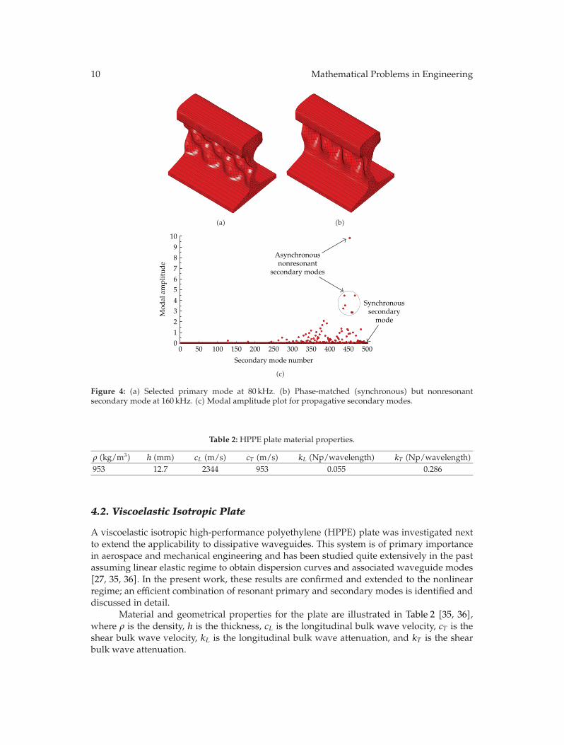
not take place. This fact translates into the very small value associated of modal amplitudeassociated with the only synchronous mode and the relatively higher values associated to theasynchronous secondary modes.
The following Figures 4(a) and 4(b) illustrate the selected primary and secondarymodes, respectively. Figure 4(c) plots the modal amplitude results as calculated from (3.2)for the propagative secondary modes present at 160 kHz.
4.1.2. Resonant Combination
In this case a flexural vertical mode was selected as primary excitation. The results of thenonlinear SAFE analysis disclosed the presence of some synchronous secondary modes withone in particular (slightly different flexural vertical type) able to verify both requirementsproducing internal resonance and a nonlinear double harmonic growing linearly withdistance. As in the previous case, Figures 5(a)-5(b) display the selected modes, whileFigure 5(c) spotlights the very high value of modal amplitude related to the secondaryresonant mode; small amplitude values associated to the other synchronousmodes, for whichpower transfer is absent, are also shown in the same figure.
The previous results point up an optimal combination of primary and secondarywave fields able to maximize the nonlinear response of the waveguide. Furthermore, itis worthwhile to notice how the selected primary mode is not only able to produce aresonant condition, but also very attractive in terms of practical excitability by a piezoelectrictransducer.
10 Mathematical Problems in Engineering
(a) (b)
10
9
8
7
6
5
4
3
2
1
0
Mod
al a
mpl
itud
e
Secondary mode number
Synchronoussecondary
mode
Asynchronousnonresonant
secondary modes
0 50 100 150 200 250 300 350 400 450 500
(c)
Figure 4: (a) Selected primary mode at 80 kHz. (b) Phase-matched (synchronous) but nonresonantsecondary mode at 160 kHz. (c) Modal amplitude plot for propagative secondary modes.
Table 2: HPPE plate material properties.
ρ (kg/m3) h (mm) cL (m/s) cT (m/s) kL (Np/wavelength) kT (Np/wavelength)953 12.7 2344 953 0.055 0.286
4.2. Viscoelastic Isotropic Plate
A viscoelastic isotropic high-performance polyethylene (HPPE) plate was investigated nextto extend the applicability to dissipative waveguides. This system is of primary importancein aerospace and mechanical engineering and has been studied quite extensively in the pastassuming linear elastic regime to obtain dispersion curves and associated waveguide modes[27, 35, 36]. In the present work, these results are confirmed and extended to the nonlinearregime; an efficient combination of resonant primary and secondary modes is identified anddiscussed in detail.
Material and geometrical properties for the plate are illustrated in Table 2 [35, 36],where ρ is the density, h is the thickness, cL is the longitudinal bulk wave velocity, cT is theshear bulk wave velocity, kL is the longitudinal bulk wave attenuation, and kT is the shearbulk wave attenuation.

Mathematical Problems in Engineering 11
(a) (b)
60
50
40
30
20
10
0
Mod
al a
mpl
itud
e
Secondary mode number
0 50 100 150 200 250 300 350 400 450 500
Resonant secondary modef = 160 kHz
k = 335.83 rad/m
Synchronousnonresonant
secondary modes
(c)
Figure 5: (a) Selected primary mode at 80 kHz. (b) Resonant secondary mode at 160 kHz. (c) Modalamplitude plot for secondary propagative modes.
The dissipative behavior of the plate was modeled via the Hysteretic formulation [27].Hence, the resultant stiffness matrix is frequency-independent andwas calculated just once atthe beginning of the analysis once the complex Lame’s constants were evaluated. The resultsfor the present case are
λ =ρc2T
((3c2L − 4c2T
)/(c2L − c2T
))ν
(1 + ν)(1 − 2ν)= 3.51 + 0.06i, GPa,
μ =ρc2T
((3c2L − 4c2T
)/(c2L − c2T
))
2(1 + ν)= 0.86 − 0.08i, GPa.
(4.1)
In (4.1) the complex bulk wave velocities (longitudinal and transverse) are calculated asfollows:
cL,T = cL,T
(1 + i
kL,T2π
)−1. (4.2)
12 Mathematical Problems in Engineering
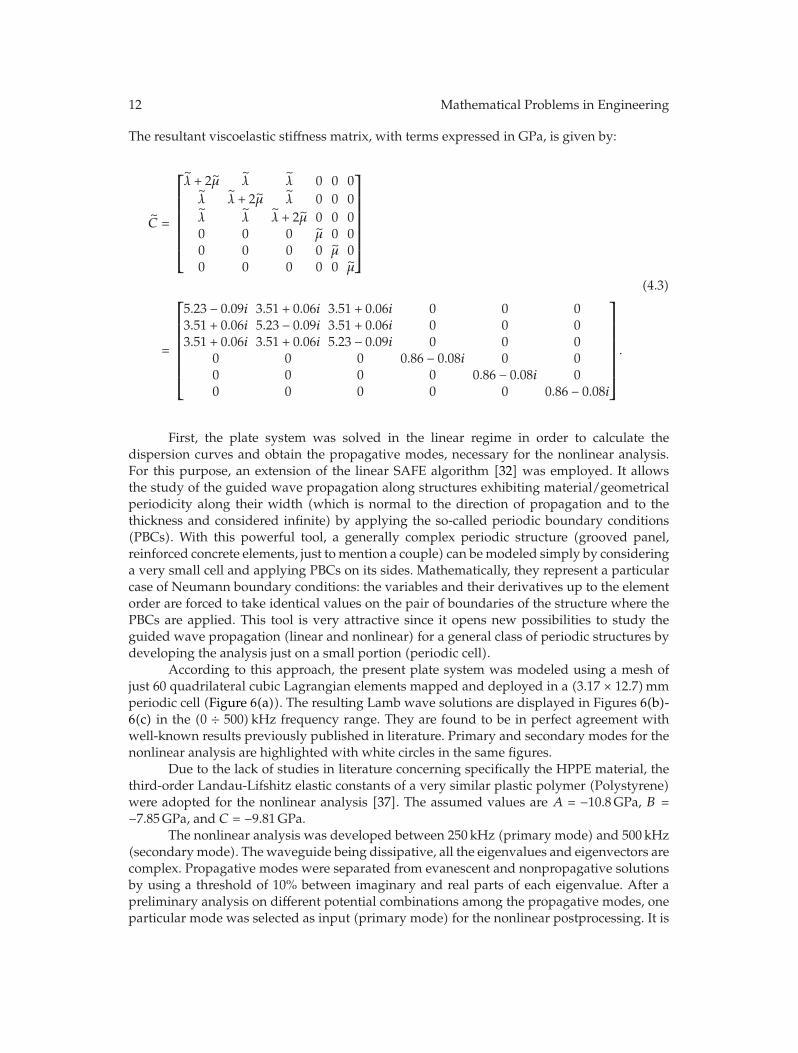
The resultant viscoelastic stiffness matrix, with terms expressed in GPa, is given by:
C =
⎡
⎢⎢⎢⎢⎢⎢⎢⎣
λ + 2μ λ λ 0 0 0λ λ + 2μ λ 0 0 0λ λ λ + 2μ 0 0 00 0 0 μ 0 00 0 0 0 μ 00 0 0 0 0 μ
⎤
⎥⎥⎥⎥⎥⎥⎥⎦
=
⎡
⎢⎢⎢⎢⎢⎢⎢⎣
5.23 − 0.09i 3.51 + 0.06i 3.51 + 0.06i 0 0 03.51 + 0.06i 5.23 − 0.09i 3.51 + 0.06i 0 0 03.51 + 0.06i 3.51 + 0.06i 5.23 − 0.09i 0 0 0
0 0 0 0.86 − 0.08i 0 00 0 0 0 0.86 − 0.08i 00 0 0 0 0 0.86 − 0.08i
⎤
⎥⎥⎥⎥⎥⎥⎥⎦
.
(4.3)
First, the plate system was solved in the linear regime in order to calculate thedispersion curves and obtain the propagative modes, necessary for the nonlinear analysis.For this purpose, an extension of the linear SAFE algorithm [32] was employed. It allowsthe study of the guided wave propagation along structures exhibiting material/geometricalperiodicity along their width (which is normal to the direction of propagation and to thethickness and considered infinite) by applying the so-called periodic boundary conditions(PBCs). With this powerful tool, a generally complex periodic structure (grooved panel,reinforced concrete elements, just tomention a couple) can bemodeled simply by consideringa very small cell and applying PBCs on its sides. Mathematically, they represent a particularcase of Neumann boundary conditions: the variables and their derivatives up to the elementorder are forced to take identical values on the pair of boundaries of the structure where thePBCs are applied. This tool is very attractive since it opens new possibilities to study theguided wave propagation (linear and nonlinear) for a general class of periodic structures bydeveloping the analysis just on a small portion (periodic cell).
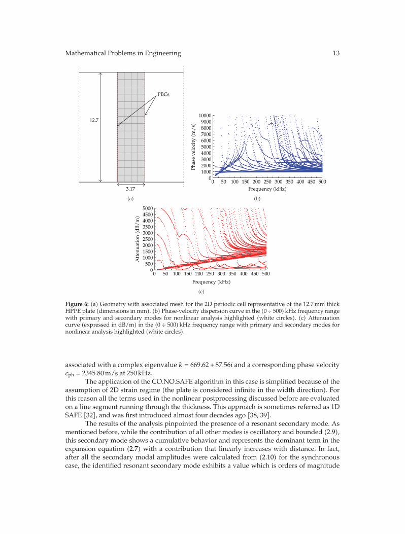
According to this approach, the present plate system was modeled using a mesh ofjust 60 quadrilateral cubic Lagrangian elements mapped and deployed in a (3.17 × 12.7)mmperiodic cell (Figure 6(a)). The resulting Lamb wave solutions are displayed in Figures 6(b)-6(c) in the (0 ÷ 500) kHz frequency range. They are found to be in perfect agreement withwell-known results previously published in literature. Primary and secondary modes for thenonlinear analysis are highlighted with white circles in the same figures.
Due to the lack of studies in literature concerning specifically the HPPE material, thethird-order Landau-Lifshitz elastic constants of a very similar plastic polymer (Polystyrene)were adopted for the nonlinear analysis [37]. The assumed values are A = −10.8GPa, B =−7.85GPa, and C = −9.81GPa.
The nonlinear analysis was developed between 250 kHz (primary mode) and 500 kHz(secondarymode). The waveguide being dissipative, all the eigenvalues and eigenvectors arecomplex. Propagative modes were separated from evanescent and nonpropagative solutionsby using a threshold of 10% between imaginary and real parts of each eigenvalue. After apreliminary analysis on different potential combinations among the propagative modes, oneparticular mode was selected as input (primary mode) for the nonlinear postprocessing. It is
Mathematical Problems in Engineering 13
PBCs
12.7
3.17
(a)
0 50 100 150 200 250 300 350 400 450 500Frequency (kHz)
10000900080007000600050004000300020001000
0
Phas
e ve
loci
ty(m
/s)
(b)
0 50 100 150 200 250 300 350 400 450 500
Frequency (kHz)
500045004000350030002500200015001000500
0
Att
enua
tion
(dB
/m)
(c)
Figure 6: (a) Geometry with associated mesh for the 2D periodic cell representative of the 12.7mm thickHPPE plate (dimensions in mm). (b) Phase-velocity dispersion curve in the (0 ÷ 500) kHz frequency rangewith primary and secondary modes for nonlinear analysis highlighted (white circles). (c) Attenuationcurve (expressed in dB/m) in the (0 ÷ 500) kHz frequency range with primary and secondary modes fornonlinear analysis highlighted (white circles).
associated with a complex eigenvalue k = 669.62 + 87.56i and a corresponding phase velocitycph = 2345.80m/s at 250 kHz.
The application of the CO.NO.SAFE algorithm in this case is simplified because of theassumption of 2D strain regime (the plate is considered infinite in the width direction). Forthis reason all the terms used in the nonlinear postprocessing discussed before are evaluatedon a line segment running through the thickness. This approach is sometimes referred as 1DSAFE [32], and was first introduced almost four decades ago [38, 39].
The results of the analysis pinpointed the presence of a resonant secondary mode. Asmentioned before, while the contribution of all other modes is oscillatory and bounded (2.9),this secondary mode shows a cumulative behavior and represents the dominant term in theexpansion equation (2.7) with a contribution that linearly increases with distance. In fact,after all the secondary modal amplitudes were calculated from (2.10) for the synchronouscase, the identified resonant secondary mode exhibits a value which is orders of magnitude
14 Mathematical Problems in Engineering
1000
800
600
400
200
0
Mod
al a
mpl
itud
e
0 50 100 150 200 250
Secondary mode number
Resonant secondary modef = 500 kHz
k = 1317.71 rad/m
Primary mode Secondary mode
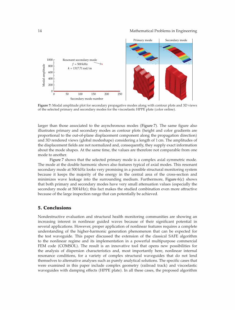
Figure 7: Modal amplitude plot for secondary propagative modes along with contour plots and 3D viewsof the selected primary and secondary modes for the viscoelastic HPPE plate (color online).
larger than those associated to the asynchronous modes (Figure 7). The same figure alsoillustrates primary and secondary modes as contour plots (height and color gradients areproportional to the out-of-plane displacement component along the propagation direction)and 3D rendered views (global modeshape) considering a length of 1 cm. The amplitudes ofthe displacement fields are not normalized and, consequently, they supply exact informationabout the mode shapes. At the same time, the values are therefore not comparable from onemode to another.
Figure 7 shows that the selected primary mode is a complex axial symmetric mode.The mode at the double harmonic shows also features typical of axial modes. This resonantsecondary mode at 500 kHz looks very promising in a possible structural monitoring systembecause it keeps the majority of the energy in the central area of the cross-section andminimizes wave leakage into the surrounding medium. Furthermore, Figure 6(c) showsthat both primary and secondary modes have very small attenuation values (especially thesecondary mode at 500 kHz); this fact makes the studied combination even more attractivebecause of the large inspection range that can potentially be achieved.
5. Conclusions
Nondestructive evaluation and structural health monitoring communities are showing anincreasing interest in nonlinear guided waves because of their significant potential inseveral applications. However, proper application of nonlinear features requires a completeunderstanding of the higher-harmonic generation phenomenon that can be expected forthe test waveguide. This paper discussed the extension of the classical SAFE algorithmto the nonlinear regime and its implementation in a powerful multipurpose commercialFEM code (COMSOL). The result is an innovative tool that opens new possibilities forthe analysis of dispersion characteristics and, most importantly here, nonlinear internalresonance conditions, for a variety of complex structural waveguides that do not lendthemselves to alternative analyses such as purely analytical solutions. The specific cases thatwere examined in this paper include complex geometry (railroad track) and viscoelasticwaveguides with damping effects (HPPE plate). In all these cases, the proposed algorithm
Mathematical Problems in Engineering 15
successfully identified optimal combinations of resonant primary and secondarywavemodesthat exhibit the desired conditions of synchronicity and large cross-energy transfer. Theseproperties can be exploited in an actual system aimed at monitoring the structural conditionof the waveguide by nonlinear waves (detect defects, measure quasi-static loads or instabilityconditions, etc.).
Acknowledgments
This paper was funded by Federal Railroad Administration Grant number FR-RRD-0009-10-01 (Mahmood Fateh, Program Manager) and by National Science Foundation Grant numberECCS-1028365 (George Maracas, Program Manager).
References
[1] Dace, G. E. Thompson, R. B. Brasche, L. J. H. Rehbein, and D. K. Buck, “Nonlinear acoustic,a technique to determine microstructural changes in material,” Review of Progress in QuantitativeNondestructive Evaluation (QNDE), vol. 10, pp. 1685–1692, 1991.
[2] C. Bermes, J. Y. Kim, J. Qu, and L. J. Jacobs, “Experimental characterization of material nonlinearityusing Lamb waves,” Applied Physics Letters, vol. 90, no. 2, Article ID 021901, 2007.
[3] P. Cawley and D. Alleyne, “The use of Lamb waves for the long range inspection of large structures,”Ultrasonics, vol. 34, no. 2–5, pp. 287–290, 1996.
[4] J. L. Rose, Ultrasonic Waves in Solid Media, Cambridge University Press, Cambridge, UK, 1999.[5] J. L. Rose, “Standing on the shoulders of giants: an example of guided wave inspection,” Materials
Evaluation, vol. 60, no. 1, pp. 53–59, 2002.[6] R. Ahmad, S. Banerjee, and T. Kundu, “Pipe wall damage detection in buried pipes using guided
waves,” Journal of Pressure Vessel Technology, Transactions of the ASME, vol. 131, no. 1, pp. 0115011–01150110, 2009.
[7] T. Kundu, S. Das, and K. V. Jata, “Health monitoring of a thermal protection system using lambwaves,” Structural Health Monitoring, vol. 8, no. 1, pp. 29–45, 2009.
[8] H. Reis, Nondestructive Testing and Evaluation for Manufacturing and Construction, Hemisphere, NewYork, NY, USA, 1990.
[9] T. Kundu, S. Banerjee, and K. V. Jata, “An experimental investigation of guided wave propagation incorrugated plates showing stop bands and pass bands,” Journal of the Acoustical Society of America, vol.120, no. 3, pp. 1217–1226, 2006.
[10] Z. A. Goldberg, “Interaction of plane longitudinal and transverse elastic waves,” Soviet Physics.Acoustics, pp. 306–310, 1960.
[11] L. K. Zarembo and V. A. Krasil’nikov, “Nonlinear phenomena in the propagation of elastic waves insolids,” Soviet Physics USPEKHI, vol. 13, no. 6, pp. 778–797, 1971.
[12] J. H. Cantrell, “Quantitative assessment of fatigue damage accumulation in wavy slip metals fromacoustic harmonic generation,” Philosophical Magazine, vol. 86, no. 11, pp. 1539–1554, 2006.
[13] J. H. Cantrell and W. T. Yost, “Nonlinear ultrasonic characterization of fatigue microstructures,”International Journal of Fatigue, vol. 23, no. 1, pp. S487–S490, 2001.
[14] W. T. Yost and J. H. Cantrell, “The effects of fatigue on acoustic nonlinearity in aluminum alloys,”Proceedings of the IEEE, vol. 2, pp. 947–954, 1992.
[15] A. A. Shah and Y. Ribakov, “Non-linear ultrasonic evaluation of damaged concrete based on higherorder harmonic generation,”Materials and Design, vol. 30, no. 10, pp. 4095–4102, 2009.
[16] N. Kim et al., “Nonlinear behaviour of ultrasonic wave at a crack,” in Review of Progress in QuantitativeNondestructive Evaluation, vol. 1211 of AIP Conference Proceedings, pp. 313–318, 2010.
[17] I. Arias and J. D. Achenbach, “A model for the ultrasonic detection of surface-breaking cracks by thescanning laser source technique,”Wave Motion, vol. 39, no. 1, pp. 61–75, 2004.
[18] S. S. Kulkarni and J. D. Achenbach, “Structural health monitoring and damage prognosis in fatigue,”Structural Health Monitoring, vol. 7, no. 1, pp. 37–49, 2008.
[19] C. Bermes, J. Y. Kim, J. Qu, and L. J. Jacobs, “Nonlinear Lamb waves for the detection of materialnonlinearity,”Mechanical Systems and Signal Processing, vol. 22, no. 3, pp. 638–646, 2008.
16 Mathematical Problems in Engineering
[20] S. Kuchler, T. Meurer, L. J. Jacobs, and J. Qu, “Two-dimensional wave propagation in an elastic half-space with quadratic nonlinearity: a numerical study,” Journal of the Acoustical Society of America, vol.125, no. 3, pp. 1293–1301, 2009.
[21] C. Nucera and F. Lanza Di Scalea, “Nonlinear ultrasonic guided waves for prestress level monitoringin prestressing strands for post-tensioned concrete structures,” Structural Health Monitoring-anInternational Journal, vol. 10, no. 6, pp. 617–629, 2011.
[22] W. J. N. De Lima and M. F. Hamilton, “Finite-amplitude waves in isotropic elastic plates,” Journal ofSound and Vibration, vol. 265, no. 4, pp. 819–839, 2003.
[23] M. Deng, “Analysis of second-harmonic generation of Lamb modes using a modal analysisapproach,” Journal of Applied Physics, vol. 94, no. 6, pp. 4152–4159, 2003.
[24] A. Srivastava, I. Bartoli, S. Salamone, and F. Lanza Di Scalea, “Higher harmonic generation innonlinear waveguides of arbitrary cross-section,” Journal of the Acoustical Society of America, vol. 127,no. 5, pp. 2790–2796, 2010.
[25] F. D. Murnaghan, Finite Deformation of an Elastic Solid, Dover, New York, NY, USA, 1967.[26] L. D. Landau and E. M. Lifshitz, Theory of Elasticity, Addison-Wesley, London, UK, 1959.[27] I. Bartoli, A. Marzani, F. Lanza di Scalea, and E. Viola, “Modeling wave propagation in damped
waveguides of arbitrary cross-section,” Journal of Sound and Vibration, vol. 295, no. 3–5, pp. 685–707,2006.
[28] B. A. Auld, “Application of microwave concepts to theory of acoustic fields and waves in solids,”IEEE Transactions on Microwave Theory and Techniques, vol. 17, no. 11, pp. 800–811, 1969.
[29] M. Deng, Y. Xiang, and L. Liu, “Time-domain analysis and experimental examination of cumulativesecond-harmonic generation by primary Lambwave propagation,” Journal of Applied Physics, vol. 109,no. 11, Article ID 113525, 2011.
[30] T. Hayashi, W. J. Song, and J. L. Rose, “Guided wave dispersion curves for a bar with an arbitrarycross-section, a rod and rail example,” Ultrasonics, vol. 41, no. 3, pp. 175–183, 2003.
[31] COMSOL, COMSOL v4.2a Multiphysics User’s Guide2011: COMSOL, Inc. 1166.[32] M. V. Predoi, M. Castaings, B. Hosten, and C. Bacon, “Wave propagation along transversely periodic
structures,” Journal of the Acoustical Society of America, vol. 121, no. 4, pp. 1935–1944, 2007.[33] S. S. Sekoyan and A. E. Eremeev, “Measurement of the third-order elasticity constants for steel by the
ultrasonic method,”Measurement Techniques, vol. 9, no. 7, pp. 888–893, 1966.[34] E. Onate, Structural Analysis with the Finite Element Method. Linear Statics ?vol. 1, 2009.[35] A. Bernard, M. Deschamps, and M. J. S. Lowe, “Energy velocity and group velocity for guided
waves propagating within an absorbing or non-absorbing plate in vacuum,” in Review of Progressin Quantitative NDE, D. O. Thompson and D. E. Chimenti, Eds., vol. 18, pp. 183–190, Plenum Press,New York, NY, USA, 1999.
[36] A. Bernard, M. J. S. Lowe, and M. Deschamps, “Guided waves energy velocity in absorbing and non-absorbing plates,” Journal of the Acoustical Society of America, vol. 110, no. 1, pp. 186–196, 2001.
[37] C. Cattani and Y. Y. Rushchitskii, Wavelet and Wave Analysis as Applied to Materials with Micro orNanostructure, Series onAdvances inMathematics for Applied Sciences,World Scientific, Hackensack,NJ, USA, 2007.
[38] S. B. Dong and R. B. Nelson, “High frequency vibrations and waves in laminated orthotropic plates,”Journal of Applied Mechanics, Transactions ASME, vol. 39, no. 3, pp. 739–745, 1972.
[39] R. B. Nelson and S. B. Dong, “High frequency vibrations and waves in laminated orthotropic plates,”Journal of Sound and Vibration, vol. 30, no. 1, pp. 33–44, 1973.

Submit your manuscripts athttp://www.hindawi.com
Hindawi Publishing Corporationhttp://www.hindawi.com Volume 2014
MathematicsJournal of
Hindawi Publishing Corporationhttp://www.hindawi.com Volume 2014
Mathematical Problems in Engineering
Hindawi Publishing Corporationhttp://www.hindawi.com
Differential EquationsInternational Journal of
Volume 2014
Applied MathematicsJournal of
Hindawi Publishing Corporationhttp://www.hindawi.com Volume 2014
Probability and StatisticsHindawi Publishing Corporationhttp://www.hindawi.com Volume 2014
Journal of
Hindawi Publishing Corporationhttp://www.hindawi.com Volume 2014
Mathematical PhysicsAdvances in
Complex AnalysisJournal of
Hindawi Publishing Corporationhttp://www.hindawi.com Volume 2014
OptimizationJournal of
Hindawi Publishing Corporationhttp://www.hindawi.com Volume 2014
CombinatoricsHindawi Publishing Corporationhttp://www.hindawi.com Volume 2014
International Journal of
Hindawi Publishing Corporationhttp://www.hindawi.com Volume 2014
Operations ResearchAdvances in
Journal of
Hindawi Publishing Corporationhttp://www.hindawi.com Volume 2014
Function Spaces
Abstract and Applied AnalysisHindawi Publishing Corporationhttp://www.hindawi.com Volume 2014
International Journal of Mathematics and Mathematical Sciences
Hindawi Publishing Corporationhttp://www.hindawi.com Volume 2014
The Scientific World JournalHindawi Publishing Corporation http://www.hindawi.com Volume 2014
Hindawi Publishing Corporationhttp://www.hindawi.com Volume 2014
Algebra
Discrete Dynamics in Nature and Society
Hindawi Publishing Corporationhttp://www.hindawi.com Volume 2014
Hindawi Publishing Corporationhttp://www.hindawi.com Volume 2014
Decision SciencesAdvances in
Discrete MathematicsJournal of
Hindawi Publishing Corporationhttp://www.hindawi.com
Volume 2014
Hindawi Publishing Corporationhttp://www.hindawi.com Volume 2014
Stochastic AnalysisInternational Journal of