high voltage. instrument transformers.acaselektrik.com/dev/wp...instrument-transformers.pdf ·...
TRANSCRIPT

HIGH VOLTAGE.INSTRUMENT TRANSFORMERS.

This document may be subject to changes. Contact ARTECHE to confi rm the characteristics and availability of the products described here.
Moving together

Instrument transformers | High voltage
CONTENTS
1. Current transformers | 4 › Oil-paper insulation › Gas insulation › Dry insulation
2. Inductive voltage transformers | 18 › Oil-paper insulation
3. Combined transformers | 26 › Oil-paper insulation
4. Capacitive voltage transformers and coupling capacitors | 34 › Oil-paper insulation
5. Auxiliary services voltage transformers | 42 › Oil-paper insulation › Gas insulation
6. Other technologies | 50 › Medium voltage outdoor instrument transformers | 52 › Voltage transformers for GIS | 53 › Optical current transformers. Digital measurement | 54 › Line traps | 55
7. Quality & environment | 56
8. Service | 58
4 Instrument transformers | High voltage
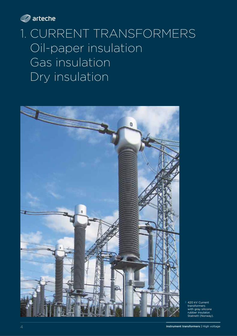
1. CURRENT TRANSFORMERSOil-paper insulationGas insulationDry insulation
› 420 kV Current transformers with gray silicone rubber insulator. Statnett (Norway).

5Instrument transformers | High voltage
Current transformers are designed to provide a scaled down replica of the current in the HV line and isolate the measuring instruments, meters, relays, etc., from the high voltage power circuit.
INTRODUCTION
Oil-paper insulation: model CA up to 800 kV, model CH up to 145 kV.
Gas insulation:model CG up to 300 kV.
Dry insulation:model CX up to 72,5 kV.
1. CURRENT TRANSFORMERS > Oil-paper, gas and dry insulation
› Model CH › Model CG › Model CA › Model CX

Instrument transformers | High voltage6
1. CURRENT TRANSFORMERS > Oil-paper, gas and dry insulation
1. Oil volume compensating system2. Oil level indicator3. Primary terminal4. Cores and secondary windings5. Primary winding
1
2
3
4
6
7
8
139
10
12
11
6. Secondary conductors7. Insulator (porcelain or silicone rubber)8. Capacitive bushing9. Reinforced earth connection10. Oil sampling valve
SECTIONS
› Madel CA › Model CH
4
13
5

7Instrument transformers | High voltage
5
› Model CG
4
6
7
13
14
15
16
3
17
9
3
18
19
45
12
› Model CX
11. Tangent delta tap 12. Earthing terminal13. Secondary terminal box14. Pressure relief device15. Head
16. Manometer17. HV electrode18. Equipotential ring19. Resin insulator
1. CURRENT TRANSFORMERS > Oil-paper, gas and dry insulation

Instrument transformers | High voltage8
APPLICATIONSIdeal for installation at metering points due to its very high accuracy.
Excellent frequency response; ideal for monitoring power quality and measuring harmonics.
Suitable for installation in AC and DC fi lters in converter substations for HVDC projects.
Examples of applications:
1. Protection for high voltage lines and substations.
2. Protection for capacitor banks.
3. Protection for power transformers.
4. Revenue metering.
M
M
M
1. 765 kV Current transformer. RAO-FSK (Russia).
2. 245 kV Current transformer protecting capacitor bank (India).
3. 420 kV Current transformers. National Grid (UK).
4. 420 kV Current transformers. Rede Eléctrica Nacional (Portugal).
1. CURRENT TRANSFORMERS > Oil-paper, gas and dry insulation

9Instrument transformers | High voltage
1. CURRENT TRANSFORMERS > Oil-paper, gas and dry insulation
› Detail of a rupture disc in a CG head.
› Metallic bellows in a CA.
With more than 65 years off expperiience,, AARRTTEECCHHEE gguuaarraannttteeeess ttthhhee ppeerrfffoorrmmaannccee oofff iiitttss tttrraannssfffoorrmmeerrss uunndddeerr cccchhhhaaaalllllllleeeennnnggggiiiinnnngggg ooooppppeeeerrrraaaattttiiiinnnngggg cccooonnndddiiitttiiiooonnnsss sssuuuccchhh aaasss eeexxxtttrrreeemmmeee ttteemmppeerraatttuurree, ssaallltttyy oorr polluted environment, seismic hazard areas, violent winds or high altitude.
The current transformer consists of one or several cores with their corresponding secondary windings (active parts)
CA RANGE:
The active parts are located in the top part inside a metal box that acts as a low-voltage shield; the main oil-paper insulation is wrapped around, ending up with a high-voltage shield. The primary conductor can be a pass-through bar (with or without external reclosings) or a winding, depending on the case. The secondary cables run through an oil-paper insulated capacitive bushing with several shields for proper electrical fi eld distribution.
CH RANGE:
The active parts are located in the bottom part. The primary conductor is hairpin shaped and the main oil-paper insulation is wrapped around it, including several intermediate capacitive shields so that the electrical fi eld is properly distributed.
CG RANGE:
The active parts are located in the top part, inside a metal box that acts as a low-voltage shield surrounded by SF6 gas insulation. The primary conductor can be a pass-through bar with or without external reclosings. The secondary conductors run through a low voltage tube to the secondary terminal block. Around this metal tube, there is a high voltage electrode so that the electrical fi eld is properly distributed.
DESIGN AND MANUFACTURECX RANGE:
The active parts are located approximately in the center of the resin body, vacuum cast with epoxy resin, which fi xes and isolates the active parts, creating a rigid body with high mechanical resistance, excellent thermal performance and dielectric withstand capability.
This resin body is inside a hollow porcelain or silicone rubber insulator. The chamber between the resin body and the insulator is hermetically sealed with nitrile rubber gaskets; this space is fi lled with oil for insulation levels above 36 kV.

Instrument transformers | High voltage10
ADVANTAGES › Variety of designs and technologies of insulation for greater adaptation to client needs.
› Robust mechanical strength and reduced size due to a compact design that is easy to transport, store and install, and which reduces visual impact.
› Hermetically sealed to guarantee complete water tightness with the minimum volume of oil or gas (Each unit is tested individually).
› Excellent response under extreme weather conditions (Oil-paper insulation from -55°C; up to +55°C; gas insulation from -45°C up to +55°C), altitudes over 1.000 m.a.s.l., seis-mic hazard areas, violent winds, etc.
› Maintenance-free throughout their lifespan. › Very high and invariable accuracy (up to 0,1%).
› Protection for the secondary windings in the terminal block.
› Wide range of primary and secondary terminals.
› Diff erent cable glands and accessories available.
› Each transformer is routine tested for par-tial discharges, tangent delta (DDF), insula-tion and accuracy. Designed to withstand all the type test included in the standards.
› Compliance to any international standards: IEC, IEEE, UNE, BS, VDE, SS, CAN, AS, NBR, JIS, GOST, NF…
› Offi cially homologated in-house testing facilities.
› May be transported and stored horizontally or vertically.
› 420 kV Current transformers, model CA. CFE, Chicoasén (Mexico).
1. CURRENT TRANSFORMERS > Oil-paper, gas and dry insulation

11Instrument transformers | High voltage
1. CURRENT TRANSFORMERS > Oil-paper, gas and dry insulation
OIL-PAPER INSULATION:
Wide range of primary currents: from 1 to 5.000 A.
Oil level compensating system that eff ectively regulates changes in oil volume mainly caused by temperature.
Oil sampling valve for periodic analysis.
The materials used for construction are recyclable and resistant to the elements. Its advanced design adheres to environmental regulations through the use of high quality insulating oils, free of PCB.
Top-core Type:
› All types of measurement and protection cores: multi-ratio, linear…
› Very high rated currents and short-circuit currents.
› Reinforced safety design, resistant to inter-nal arc.
› Metallic oil bellows and tangent delta mea-surement tap.
Hairpin Type:
› Excellent seismic performance. › Good heat dissipation in the primary conductor.
› Reduced size makes it extremely easy to handle.
› Option for metallic oil bellows and tangent delta measurement tap.
OPTIONS:
› Silicone rubber insulator. › Capacitive voltage tap.
GAS INSULATION:
› Total safety in case of internal arc: overpressure is relieved by the pressure relief device (rupture disc) in the top part of the head.
› The silicone rubber insulator guarantees safety during transportation and service.
› Online monitoring of the insulation status with a manometer alarm.
› Compact and very light design. › Designed to minimize gas volume, pressure and leaks, thus reducing its environmental impact.
DRY INSULATION:
› Cast in high dielectric strength resin. › Primary winding with spark gap for over-voltage protection.
› Compact design for easy handling. › May be transported, stored and installed vertically or horizontally.
› Porcelain or silicone rubber insulators.
Innovations in transformers iin recent yyears hhave madde ttthhheemm mmoorree eeffiffiffi cciiieennttt wwiiittthhh ccoommppaaccttt dddeessiiiggnnss, mmaakkkiiinngg tttthhhheeeemmmm eeeeaaaassssyyyy ttttoooo ttttrrrraaaannnnssssppppoooorrrrtttt, ssstttooorrreee aaannnddd iiinnnssstttaaallllll;;; mmmiiinnniiimmmiiizzziiinnnggg vviiissuuaalll iiimmppaaccttt.

12 Instrument transformers | High voltage
ARTECHE transformers are installed in over 150 countries.

Instrument transformers | High voltage
1. CURRENT TRANSFORMERS > Oil-paper, gas and dry insulation
RANGEARTECHE current transformers are named with the letters CA (top-core type, oil-paper) CH (hairpin type, oil-paper), CG (gas type) or CX (dry type) followed by 2 or 3 numbers indicating the maximum service voltage for which they have been designed.
The table on the next page shows the range manufactured by ARTECHE. These charac-teristics are merely indicative; ARTECHE can manufacture transformers to comply with any domestic or international standard.
Winding ratios: all types of combinations possible in a single device.
Secondary windings for:
› Protection: all possible types, including linear cores, low induction, etc.
› 420 kV Current transformers. Tennet (The Netherlands).
› 123 kV Current transformers. Eesti Energia (Estonia).
› Metering: accuracy classes for any metering/billing need (including high accuracy class 0,1 / 0,15 with extended range in current).
Number of secondary windings: as per customer needs, up to 10 secondary windings (or more) are possible in a single device.

Instrument transformers | High voltage14
1. CURRENT TRANSFORMERS > Oil-paper, gas and dry insulation
$$06
$$02
H
T
A
> Modelo CA > Modelo CG
A
H
T
> Modelo CX
A
H
> Modelo CH
A
H
T
› Routine test perfomed on a CG 145 kV.
› 36 kV Current transformers. Fingrid, Kimy (Finland).

15Instrument transformers | High voltage
Primary currents: from 1 A to 5.000 A. Short circuit currents: up to 120 kA.
Oil-paper insulation > Model CA
ModelHighest voltage
(kV)
Rated insulation levelStandard creepage distance
(mm)
Dimensions
Weight(kg)Power
frequency (kV)
Lightning impulse
(BIL)(kVp)
Switching impulse (kVp)
A(mm)
T(mm)
H(mm)
CA-36 36 70 170 - 900 350 1.185 1.625 250
CA-52 52 90 250 - 1.300 350 1.185 1.625 260
CA-72 72,5 140 325 - 1.825 350 1.335 1.775 280
CA-100 100 185 450 - 2.500 350 1.335 1.775 290
CA-123 123 230 550 - 3.075 350 1.665 2.095 300
CA-145 145 275 650 - 3.625 350 1.665 2.095 310
CA-170 170 325 750 - 4.250 350 1.895 2.335 330
CA-245 245460 1.050
- 6.125 450 2.755 3.055 560395 950
CA-300 300 460 1.050 850 7.500 450 3.170 3.580 650
CA-362 362 510 1.175 950 9.050 600 3.875 4.355 870
CA-420 420630 1.425
1.050 10.500 600 3.875 4.355 920575 1.300
CA-525 (525) 550 680 1.550 1.175 13.125 600 4.530 5.365 1.200
CA-550 (525) 550 800 1.800 1.175 13.750 600 5.205 5.960 1.700
CA-765 (765) 800880 1.950 1.425
15.300 600 5.770 6.590 2.050 975 2.100 1.550
Approximate dimensions and weights. For special requirements, please consult.
Oil-paper insulation > Model CH
ModelHighest voltage
(kV)
Rated insulation levelStandard creepage distance
(mm)
Dimensions
Weight(kg)
Power frequency
(kV)
Lightning impulse
(BIL)(kVp)
A(mm)
T(mm)
H(mm)
CH-36 36 70 170 900 330 1.450 1.765 330
CH-52 52 90 250 1.300 330 1.450 1.765 330
CH-72 72,5 140 325 1.825 330 1.690 2.005 370
CH-100 100 185 450 2.500 330 1.690 2.005 380
CH-123 123 230 550 3.075 330 2.090 2.405 410
CH-145 145 275 650 3.625 330 2.250 2.565 430
Approximate dimensions and weights. For special requirements, please consult.
Primary currents: from 1 A to 2.000 A. Short circuit currents: up to 48 kA.
1. CURRENT TRANSFORMERS > Oil-paper, gas and dry insulation

Instrument transformers | High voltage16
Gas insulation > Model CG
ModelHighest voltage
(kV)
Rated insulation levelStandard creepage distance
(mm)
Dimensions
Weight(kg)
Power frequency
(kV)
Lightning impulse
(BIL)(kVp)
Switching Impulse (kVp)
A(mm)
T(mm)
H(mm)
CG-145 123 230 550 - 3.625 450x450 1.895 2.330 205
CG-145 145 275 650 - 3.625 450x450 1.895 2.330 205
CG-170 170 325 750 - 4.250 450x450 2.070 2.505 235
CG-245 245395 950 -
6.125 450x450 2.795 3.370 400460 1.050 -
CG-300 300 460 1.050 850 7.500 450x450 3.180 3.755 430
Approximate dimensions and weights. For special requirements, please consult.
Primary currents: up to 5.000 A. Short circuit currents: up to 120 kA/1 s.
Dry insulation > Model CX
ModelHighest voltage
(kV)
Rated insulation levelStandard creepage distance
(mm)
Dimensions
Weight(kg)Power
frequency(kV)
Lightning impulse
(BIL)(kVp)
A(mm)
H(mm)
CXD-24 24 50 125 744 210 462 43
CXE-24 24 50 125 744 250 480 72
CXE-36 36 70 170 900 250 532 80
CXG-36 36 70 170 900 250 670 150
CXE-52 52 90 250 1440 250 712 111
CXG-52 52 90 250 1560 250 798 186
CXH-52 52 90 250 1560 330 800 263
CXG-72 72,5 140 325 1860 250 918 190
CXH-72 72,5 140 325 1860 330 920 305
Approximate dimensions and weights. For special requirements, please consult.
1. CURRENT TRANSFORMERS > Oil-paper, gas and dry insulation
Primary currents: from 1 A to 2.400 A. Short circuit currents: up to 120 kA/1 s.

Instrument transformers | High voltage 17
Over 2.100 professionals committed to a common project.

18 Instrument transformers | High voltage
2. INDUCTIVE VOLTAGE TRANSFORMERS
Oil-paper insulation
› 123 kV Inductive voltage transformers. Fingrid (Finland).

19Instrument transformers | High voltage
Inductive voltage transformers are designed to provide a scaled down replica of the voltage in the HV line and isolate the measuring instruments, meters, relays, etc., from the high voltage power circuit.
INTRODUCTION
2. INDUCTIVE VOLTAGE TRANSFORMERS > Oil-paper insulation
› Model UTF › Model UTE
Model UT up to 550 kV.
› Model UTD

Instrument transformers | High voltage20
> Up to 300 kV
1
2
3
4
5
6
7
8
9
13
10
14
11
12
8
> From 362 kV
SECTIONS1. Oil level indicator2. Primary terminal3. Oil volume compensating system4. Capacitive bushing5. Oil-paper insulation6. Compensation windings7. Primary windings
8. Secondary windings9. Core10. Insulator (porcelain or silicone rubber)11. Tangent delta measuring tap12. Secondary terminal box13. Oil sampling valve14. Earthing terminal
2. INDUCTIVE VOLTAGE TRANSFORMERS > Oil-paper insulation
7
9

21Instrument transformers | High voltage
Examples of applications:
1. Revenue metering.
2. Discharge of capacitor lines and banks.
3. Protection for high voltage lines and substations.
4. Supply for auxiliary services.
APPLICATIONSIdeal for installation at metering points due to its very high accuracy class.
Suitable for the discharge of high-voltage lines and capacitor banks.
Excellent frequency response; ideal for monitoring power quality and measuring harmonics.
M
1. 123 kV Inductive voltage transformers (Bosnia).
2. 123 kV Inductive voltage transformers. Transpower (New Zealand).
3. 420 kV Inductive voltage transformers.Rede Eléctrica Nacional (Portugal)
4. 245 kV Inductive voltage transformer. Coyote Switch (USA).
2. INDUCTIVE VOLTAGE TRANSFORMERS > Oil-paper insulation

Instrument transformers | High voltage22
Voltage transformers can have several secondary windings for metering and/or protection. The primary winding and all the secondary windings are wound around the same core, which is loaded with the total burden.
The core and the windings are located inside a metallic tank. The windings have an anti-resonant design, which makes the transformer work properly both at power frequency and during temporary high frequency transients.
› Oil level indicator.
› Various types of insulators available (silicone, gray porcelain, colored porcelain ….).
HHHHHiiiiiggggghhhhh aaaannnnddddd ssssttttteeeeaaaadddddyyyyy aaaaccccccccuuuurrrraaaaccccyyyyy,, cccooommmbbbbiiiinnneeedddd wwwiiiitttthhhh sssaaaffffeee ddddeeesssiiiigggggnnn aanndddd mmaaxxiiiimmuumm rreelllliiiiaabbbbiiiilllliiiitttyyy.
2. INDUCTIVE VOLTAGE TRANSFORMERS > Oil-paper insulation
ADVANTAGES
DESIGN AND MANUFACTURE
› Very high and invariable accuracy (up to 0,1%) steady for the operation life of the equipment, with maximum reliability.
› Anti-resonant winding design. › Safe design in case of internal fault thanks to:- Active parts located inside metallic tank,
separated from the insulator.- Pressure relief devices.- Electrical connections resistant to short
circuit. › Robust mechanical strength and reduced size due to a compact design that is easy to transport, store and install, and which reduces visual impact.
› Oil level compensating system that eff ec-tively regulates changes in oil volume mainly caused by temperature.
› Hermetically sealed to guarantee complete water tightness with the minimum volume of oil or gas. (Each unit is tested individu-ally).
› Oil sampling valve for periodic analysis. › Maintenance-free throughout their lifespan.

23Instrument transformers | High voltage
OPTIONS:
› Wide range of primary and secondary terminals.
› Silicone rubber insulator. › Sealable secondary terminals. › Secondary terminal protection devices inside the terminal box.
› Oil compensation system with metallic bellows. Option for rubber diaphragm up to 170 kV.
› Current through connection to the HV: line. › Vertical primary terminal.
› 420 kV Inductive voltage transformers. R.E.E. (Spain).
2. INDUCTIVE VOLTAGE TRANSFORMERS > Oil-paper insulation
› Environmental-friendly design through the use of high quality insulating oils free of PCB. The materials used are recyclable and resistant to the elements.
› Excellent response under extreme weather conditions (from -55°C; up to +55°C), altitudes over 1000 m.a.s.l., seismic hazard areas, violent winds, etc.
› Each transformer is routine tested for par-tial discharges, tangent delta (DDF), insula-tion and accuracy. Designed to withstand all the type test included in the standards.
› Compliance to any international standards: IEC, IEEE, UNE, BS, VDE, SS, CAN, AS, NBR, JIS, GOST, NF.
› Offi cially homologated in-house testing facilities.
› May be transported and stored horizontally or vertically.

Instrument transformers | High voltage24
RANGEARTECHE inductive voltage transformers are named with the letters (UT) followed by 1 additional letter and 2 or 3 numbers indicating the maximum voltage of the network for which they are designed.
The table on the next page shows the range of both types of transformers currently manufactured by ARTECHE. These characteristics are merely indicative; ARTECHE can manufacture them to comply with any domestic or international standard.
Standard accuracy classes and burdens:
› According to IEC standards 100 VA Class 0,2 / 3P 250 VA Class 0,5 / 3P › According to IEEE standards
0.3 WXYZ 1.2 WXYZ, ZZHigher accuracy classes and burdens available.
› 123 kV Inductive voltage transformers. Electronet Services (New Zealand).
› 420 kV Inductive voltage transformers.Elia (Belgium).
H
B
A
› Model UTF from 362 kV
H
A
› Model UTB/UTD/UTE/UTF/UTG up to 300 kV
B
2. INDUCTIVE VOLTAGE TRANSFORMERS > Oil-paper insulation

25Instrument transformers | High voltage
Oil-paper insulation > Model UT
ModelHighest voltage
(kV)
Rated insulation level
Thermal burden
(VA)
Standard creepage distance
(mm)
Dimensions
Weight(kg)Power
frequency (kV)
Lightning impulse
(BIL) (kVp)
Switching impulse (kVp)
A x B(mm)
H(mm)
UTB-52 52 95 250 - 1.500 1.300 300x300 1.335 95
UTD-52 52 95 250 - 2.000 1.300 330x300 1.395 150
UTB-72 72,5 140 325 - 1.500 1.825 300x300 1.335 108
UTD-72 72,5 140 325 - 2.000 1.825 330x300 1.395 150
UTE-72 72,5 140 325 - 2.500 1.825 400x430 1.645 285
UTD-100 100 185 450 - 2.000 2.500 330x300 1.690 165
UTD-123 123 230 550 - 3.000 3.075 350x475 2.120 292
UTE-123 123 230 550 - 3.500 3.075 350x475 2.120 355
UTE-145 145 275 650 - 3.500 3.625 350x475 2.105 335
UTE-170 170 325 750 - 3.500 4.250 350x475 2.235 350
UTF-245 245460 1.050
- 3.500 6.125 450x590 3.210 650395 950
UTG-245 245460 1.050
- 3.500 6.125 500x640 3.260 800395 950
UTG-300 300 460 1.050 850 3.500 7.500 500x640 3.660 910
UTF-420 420630 1.425 1.050
3.500 10.500 600x600 5.210 1.315575 1.300 950
UTF-525 550 (525) 680 1.550 1.175 3.500 1.3125 600x600 6.070 1.700
Approximate dimensions and weights. For special requirements, please consult.
2. INDUCTIVE VOLTAGE TRANSFORMERS > Oil-paper insulation

26 Instrument transformers | High voltage
3. COMBINED TRANSFORMERS Oil-paper insulation
› 123 kV Combined transformers.

27Instrument transformers | High voltage
Combined Instrument Transformers contain a current transformer and an inductive voltage transformer within the same body.
They are therefore used in the same applications as the independent transformers in them; they separate meters, counters, relays, etc., from the high voltage circuit, and provide a scaled replica of the current and voltage in the HV line.
INTRODUCTION
Model KA up to 245 kV.
3. COMBINED TRANSFORMERS > Oil-paper insulation
› Model KA

Instrument transformers | High voltage28
> Up to 245 kV
1
2
3
6
7
8
9
13
10
14
1112
5
SECTIONS1. Oil volume compensating system2. Oil level indicator3. Primary terminal (P1)4. CT primary winding5. CT secondary winding6. Primary terminal (P2)7. CT cores8. Insulator (Porcelain or silicone rubber)
9. VT capacitive bushing10. CT capacitive bushing11. VT primary winding12. Secondary terminal box13. VT secondary winding14. VT core15. Earthing terminal16. Oil sampling valve
3. COMBINED TRANSFORMERS > Oil-paper insulation
4
15
16

29Instrument transformers | High voltage
APPLICATIONSCombined transformers are suitable for use in substations where space or installation costs make using independent transformers diffi cult.
Ideal for installation at metering points due to their very high accuracy class, both in current and voltage.
Suitable for the discharge of high-voltage lines and capacitor banks.
Excellent frequency response; ideal for monitoring power quality and measuring harmonics.
3. COMBINED TRANSFORMERS > Oil-paper insulation
› 72,5 kV Combined transformers in substation incoming line. L’ONE (Morocco).
Examples of applications:
1. Protection for high voltage lines and substations.
2. Revenue metering.
M

Instrument transformers | High voltage30
Combined transformers gather the manufacturing characteristics of current transformers (CA type) and inductive voltage transformers (UT type).
The CT active parts are located in the top part inside a metal box that acts as a low-voltage shield; the main oil-paper insulation is wrapped around it, ending up with a high-voltage shield. The primary conductor can be a pass-through bar (with or without external reclosings) or a winding, depending on the case. The secondary cables run through an oil-paper insulated capacitive bushing with several shields for proper electrical fi eld distribution.
Voltage transformers can have several secondary windings for metering and/or protection. The primary winding and all the secondary windings are wound around the same core, which is loaded with all the burden.
The core and the windings are located inside a metallic tank. The windings have an anti-resonant design, which makes the transformer work properly both at power frequency and during temporary high frequency transients.
› Wide variety of primary terminals.
› Can be transported horizontally.
ARTECHE’S experience wiithh majjjor transmiissiion llliiinneess eexxpplllaaiiinnss wwhhhyy wwee aarree aa kkkeeyy fififi gguurree iiinn fffuutttuurree ppoowweerr lllliiiinnnnkkkkssss bbbbeeeettttwwwweeeeeeeennnn ccccoooouuuunnnnttttrrrriiiieeeessss aaaannnndddd cccooonnntttiiinnneeennntttsss.
3. COMBINED TRANSFORMERS > Oil-paper insulation
DESIGN AND MANUFACTURE

31Instrument transformers | High voltage
OPTIONS:
› Silicone rubber insulation. › Tangent delta measurement tap and ca-pacitive tap.
› Wide range of primary and secondary terminals.
› Diff erent cable glands and accessories available. › 123 kV Combined
Transformers. ESB (Ireland).
3. COMBINED TRANSFORMERS > Oil-paper insulation
› Less space needed in the substation, trans-portation and storage.
› Savings:- Support structures, connectors and
installation time.- Inspection and maintenance.- Spare parts.
› Excellent response under extreme weather conditions (from -55°C; up to +55°C), altitudes over 1.000 m.a.s.l., seismic hazard areas, violent winds, etc.
› Robust mechanical strength and reduced size due to a compact design that is easy to transport, store and install, and which reduces visual impact.
› Hermetically sealed to guarantee complete water tightness with the minimum volume of oil or gas. (Each unit is tested individually)
› Reinforced safety design, resistant to internal arc.
› Oil level compensating system that ef-fectively regulates changes in oil volume mainly caused by temperature.
› Oil sampling valve for periodic analysis. › Maintenance-free throughout their lifespan.
ADVANTAGES › Environmental-friendly design through the use of materials recyclable and resistant to the elements. Its advanced design adheres to environmental regulations through the use of high quality insulating oils, free of PCB.
› Each transformer is routine tested for par-tial discharges, tangent delta (DDF), insula-tion and accuracy. Designed to withstand all the type test included in the standards.
› Compliance to any international standards: IEC, IEEE, UNE, BS, VDE, SS, CAN, AS, NBR, JIS, GOST, NF…
› Offi cially homologated in-house testing facilities.
› May be transported and stored horizontally or vertically.

Instrument transformers | High voltage32
RANGEARTECHE combined instrument transformers with oil-paper insulation are named with the letters KA followed by 2 or 3 numbers indicating the maximum service voltage for which they have been designed.
The table on the next page shows the range of combined transformers currently manufac-tured by ARTECHE. These characteristics are merely indicative; ARTECHE can manufacture these transformers to comply with any do-mestic or international standard.
Current ratios: all types of combinations possible in a single device.
Secondary windings for:
› Protection: all possible types, including linear cores, low induction, etc.
› Metering: accuracy classes for any metering/billing need (including high accuracy class 0,1 / 0,15 with extended range in current).
Number of secondary windings: as per customer needs.
Standard accuracy classes and burdens for voltage transformer:
› According to IEC standards 100 VA Class 0,2 / 3P 250 VA Class 0,5 / 3P › According to IEEE standards
0.3 WXYZ 1.2 WXYZ, ZZ
Higher accuracy classes and burdens available.
H
T
A
> Model KA
3. COMBINED TRANSFORMERS > Oil-paper insulation
B
› 170 kV Combined transformers. Pechiney (The Netherlands).
› 69 kV Combined transformers. Greenville Light & Power Systems (USA).

33Instrument transformers | High voltage
Oil-paper insulation > Model KA
ModelHighest voltage
(kV)
Rated insulation levelStandard creepage distance
(mm)
No. secondaries*
Dimensions(mm)
Weight(kg)Power
frequency (kV)
Lightning impulse
(BIL) (kVp)
AXB T H
KA-72 72,5 140 325 2.525TI 5
350x475 1.615 2.055 376TT 3
KA-123 123 230 550 3.880TI 5
350x475 2.195 2.795 580TT 3
KA-145 145 275 650 3.880TI 5
350x475 2.195 2.795 580TT 3
KA-170 170 325 750 4.490TI 5
350x475 2.375 2.795 750TT 3
KA-245 245460 1.050
6.865TI 5
450x590 3.315 3.850 1.100395 950 TT 3
Approximate dimensions and weights. For special requirements, please consult.
*TI: Current transformer *TT: Voltage transformer
3. COMBINED TRANSFORMERS > Oil-paper insulation

34 Instrument transformers | High voltage
4. CAPACITIVE VOLTAGE TRANSFORMERS AND COUPLING CAPACITORS
Oil-paper insulation
› 420 kV Capacitive voltage trasnformers. Fingrid, Visulahti (Finland).

35Instrument transformers | High voltage
Capacitive voltage transformers isolate the measuring instruments, meter, relays, protec-tions, etc., from the high voltage power circuit and provide a scaled replica of the voltage in the HV line.
› Model DFK
INTRODUCTION
Capacitive voltagetransformermodel DFK up to 800 kV,model DDB up to 170 kV.
Coupling capacitor: model DFN up to 800 kV,model DDN up to 170 kV.
4. CAPACITIVE VOLTAGE TRANSFORMERS AND COUPLING CAPACITORS > Oil-paper insulation
› Model DDN › Model DDB
They enable transmission of high frequency signals through the high voltage HV lines.
Coupling Capacitors are only used for coupling high frequency communication signals and they are equivalent to the capacitive part of a CVT.

Instrument transformers | High voltage36
> Coupling capacitor
1
2
3
4
5
6
7
9
10
11
12
8
> Capacitive voltage transformer
SECTIONS1. Primary terminal2. Oil volume compensating system3. Insulator (porcelain or silicone rubber)4. Capacitors5. Intermediate voltage tap6. High frequency terminal
7. Inductive voltage transformer8. Oil level indicator9. Carrier accessories10. Oil sampling valve11. Earthing terminal12. Secondary terminal box
4. CAPACITIVE VOLTAGE TRANSFORMERS AND COUPLING CAPACITORS > Oil-paper insulation

37Instrument transformers | High voltage
APPLICATIONSIdeal for installation at metering points due to its very high accuracy class and extremely steady capacitance.
Transmission of high-frequency signals through the high voltage lines (PLC).
Helps to reduce voltage peaks in the line.
› 400 kV Capacitive voltage transformers. R.E.E. (Spain).
4. CAPACITIVE VOLTAGE TRANSFORMERS AND COUPLING CAPACITORS > Oil-paper insulation
Examples of applications:
1. Revenue metering.
2. Protection for high voltage lines and substations.
3. Transmission of high frequency signals.
M

Instrument transformers | High voltage38
Capacitive voltage transformers consist of a series of capacitors connected in series on top of a tank in which the electromagnetic unit (inductive transformer (5), series reactor (8) and auxiliary elements) is housed. These capacitors form a voltage divider (2, 3) between the high voltage terminal (1) and the high frequency terminal (4).
The capacitors, impregnated with high grade dielectric oil, are housed in one or more insulators. Each of them forms an hermetically sealed independent unit, with a very stable capacitance over time. The high frequency terminal (4) for the PLC signal comes out of one side through a piece of resin that separates the capacitive unit from the inductive voltage transformer.
The medium voltage inductive voltage transformer is immersed in mineral oil and housed inside an hermetically sealed metallic tank.
The secondary terminals are located inside a box (7) enabling connections and has space with protection elements such as fuses or circuit breakers.
› Earthing switch for safety handling during operation.
› Protection devices for the secondaries may be installed inside the terminal block.
DESIGN AND MANUFACTURE
2
1
3
5
4
6
6
7
8
1. Primary terminal2. Capacitors3. Capacitors4. High frequency terminal5. Inductive voltage transformer6. Ferroresonance suppression circuit7. Secondary terminal box8. Compensating reactor
4. CAPACITIVE VOLTAGE TRANSFORMERS AND COUPLING CAPACITORS > Oil-paper insulation

39Instrument transformers | High voltage
› High stability of capacity, and therefore of accuracy.
› Reliable ferroresonance suppression sys-tem that does not aff ect transient response or accuracy.
› Excellent mechanical resistance to seismic forces.
› Pressure relief device to guarantee maxi-mum safety.
› Robust mechanical strength and reduced size due to a compact design that is easy to transport, store and install, and which reduces visual impact.
› Hermetically sealed to guarantee complete water tightness with the minimum volume of oil or gas (Each unit is tested individually).
› Oil level compensating system that eff ec-tively regulates changes in oil volume.
› Maintenance-free throughout their lifespan. › Environmental-friendly design through the use of materials recyclable and resistant to the elements. Its advanced design adheres to environmental regulations through the use of high quality insulating oils, free of PCB.
› Excellent response under extreme weather conditions (from -55°C; up to +55°C), altitudes over 1.000 m.a.s.l., seismic hazard areas, violent winds, etc.
› Each transformer is routine tested for par-tial discharges, tangent delta (DDF), insula-tion and accuracy. Designed to withstand all the type test included in the standards.
› Compliance to any international standards: IEC, IEEE, UNE, BS, VDE, SS, CAN, AS, NBR, JIS, GOST, NF…
› Offi cially homologated in-house testing facilities.
OPTIONS:
› Silicone rubber insulation. › Carrier accessories. › Earthing switch for the inductive part. › Wide range of primary and secondary terminals.
› Sealable secondary terminals. › Line traps can be installed on the top. › Diff erent cable glands and accessories available.
› Wide range of capacitances. › Secondary terminal protection devices inside the terminal box.
ADVANTAGES
MMMMaaaaxxxxiiiimmmmuuuummmm ssssaaaaffffeeeettttyyyy aaaannnndddd rreellliiiaabbbiiillliiitttyy wwiiittthhhiiinn aa custtom-madde ddesiiggggn.
4. CAPACITIVE VOLTAGE TRANSFORMERS AND COUPLING CAPACITORS > Oil-paper insulation

Instrument transformers | High voltage40
RANGEARTECHE capacitive voltage transformers and coupling capacitors are named with diff erent letters (DDB or DFK for transformers; DDN or DFN for capacitors) followed by 2 or 3 numbers indicating the maximum voltage of the network for which they are designed.
The tables show the ranges of both types of devices currently built by ARTECHE. These characteristics are merely indicative; they can be manufactured to comply with any domestic or international standard.
Standard accuracy classes and powers:
› According to IEC standards 100 VA Class 0,2 / 3P 250 VA Class 0,5 / 3P › According to IEEE standards
0.3 WXYZ 1.2 WXYZ, ZZ
Higher accuracy classes and burdens available.
› 245 kV Capacitive voltage transformers. NEPCO (Jordan).
› 525 kV Capacitive voltage transformers. UTE (Uruguay).
H
H
A
A
> Coupling capacitor > Capacitive voltage transformer
A
A
4. CAPACITIVE VOLTAGE TRANSFORMERS AND COUPLING CAPACITORS > Oil-paper insulation

41Instrument transformers | High voltage
Capacitive voltage transformers
ModelHighest Voltage
(kV)
Rated insulation level
Standard capacitance
(pF)
High capacitance
(pF)
Standard creepage distance
(mm)
Dimensions
Weight (kg)Power
frequency (kV)
Lightning impulse
(BIL) (kVp)
Switching impulse (kVp)
A(mm)
H(mm)
DDB-72 72,5 140 325 - 10.300 25.500 1.825 450 1.510 245
DDB-100 100 185 450 - 5.700 14.300 2.500 450 1.600 255
DDB-123 123 230 550 - 5.600 14.000 3.075 450 1.830 300
DDB-145 145 275 650 - 3.900 19.500 3.625 450 1.920 310
DDB-170 170 325 750 - 7.500 16.500 4.250 450 2.065 330
DFK-245 245460 1.050
- 5.800 11.000 6.125 450 2.885 450395 950
DFK-300 300 460 1.050 850 6.000 12.500 7.500 450 3.205 480
DFK-362 362 510 1.175 950 4.500 10.100 9.050 450 3.675 520
DFK-420 420630 1.425 1.050
3.500 7.700 10.500 450 4.595 670575 1.300 950
DFK-525 (525) 550680 1.550 1.175
3.000 6.200 13.125 450 5.560 1.065800 1.800 1.175
DFK-765 (765) 800880 1.950 1.425
3.000 4.500 15.300 450 7.010 1.270975 2.100 1.550
Approximate dimensions and weights. For special requirements, please consult. Higher capacities available upon request.
Coupling capacitors
ModelHighest Voltage
(kV)
Rated insulation level
Standard capacitance
(pF)
High capacitance
(pF)
Standard creepage distance
(mm)
Dimensions
Weight (kg)Power
frequency (kV)
Lightning impulse
(BIL) (kVp)
Switching impulse (kVp)
A(mm)
H(mm)
DDN-72 72,5 140 325 - 10.300 25.500 1.825 450 1.235 115
DDN-100 100 185 450 - 5.700 14.300 2.500 450 1.325 120
DDN-123 123 230 550 - 5.600 14.000 3.075 450 1.585 145
DDN-145 145 275 650 - 3.900 19.500 3.625 450 1.675 150
DDN-170 170 325 750 - 7.500 16.500 4.250 450 1.805 170
DFN-245 245460 1.050
- 5.800 11.000 6.125 450 2.625 255
DFN-300 300 460 1.050 850 6.000 12.500 7.500 450 2.945 305
DFN-362 362 510 1.175 950 4.500 10.100 9.050 450 3.415 345
DFN-420 420630 1.425 1.050
3.500 7.700 10.500 450 4.335 495575 1.300 950
DFN-525 (525) 550680 1.550 1.175
3.000 6.200 13.125 450 5.300 890800 1.800 1.173
DFN-765 (765) 800880 1.950 1.425
3.000 4.500 15.300 450 6.760 1.095975 2.100 1.550
Approximate dimensions and weights. For special requirements, please consult. Higher capacities available upon request.
4. CAPACITIVE VOLTAGE TRANSFORMERS AND COUPLING CAPACITORS > Oil-paper insulation

42 Instrument transformers | High voltage
5. AUXILIARY SERVICES VOLTAGE TRANSFORMERS Oil-paper insulation Gas insulation
› 245 kV Transformer for substation auxiliary services, model UTP. Coyote Switch (USA).

43Instrument transformers | High voltage
› Model UTP
5. AUXILIARY SERVICES VOLTAGE TRANSFORMERS > Oil-paper and gas insulation
Oil-paper insulation: model UT up to 245 kV and 10 kVA; model UTP up to 362 kV and 333 kVA.
Gas insulation:model SVR up to 550 kV and 50 kVA.
This type of voltage transformer can supply several kVA low voltage power directly from a high voltage transmission line. It off ers all the benefi ts of a potential transformer with the applications of a distribution transformer.
INTRODUCTION
› Model UT › Model SVR

Instrument transformers | High voltage44
APPLICATIONS1. Substations auxiliary services power
supply:Power supply in conventional substations where low voltage power is needed as a primary or back-up supply; or in remote areas where building distribution lines is unsafe and with unreliable supply that requires frequent maintenance and high costs.
It can also be used as a primary power source in switching substations without power transformers to supply the substation and SCADA control systems.
2. Power supply for telecommunication and monitoring systems:High quality electrical supply for booster antennas in remote locations using a voltage transformer connected to a nearby transmission line.
› UTP-245 Voltage transformer for rural electrifi cation. Chihuahua State (Mexico).
3. Rural electrifi cation of isolated popula-tions: As a power source for supplying reliable power to rural populations in isolated areas where there are no distribution lines nearby, but there are transmission lines. This particular application supplies low voltage power directly from HV line in an economical and practical way.
4. Temporary power supply when building substations, wind farms, etc., and emer-gency supply during natural disasters.
5. AUXILIARY SERVICES VOLTAGE TRANSFORMERS > Oil-paper and gas insulation

45Instrument transformers | High voltage
5. AUXILIARY SERVICES VOLTAGE TRANSFORMERS > Oil-paper and gas insulation
Voltage transformers for auxiliary services with oil-paper insulation are made with a magnetic core inside a metallic tank with its primary and secondary windings around it. The primary conductor is enclosed by a capacitive bushing consisting of shields and layers of insulating paper impregnated in oil. In order to control oil level changes, they are fi tted with metallic bellows.
Voltage transformers for auxiliary services with gas insulation are made with a magnetic core inside a metallic tank with its primary and secondary windings around it. These windings are made of heat-resisting electric wires coated in synthetic resin and a layer of plastic with a high dielectric resistance and excellent thermal and mechanical performance.
The SF6 and the plastic layer form the electrical insulation. An input valve for SF6 gas is provided on a side of tank together with a manometer for monitoring leakages and gas pressure.
DESIGN AND MANUFACTURE
› UTE Voltage transformer installation.
› Packing for transporting SVR-20 transformers.

Instrument transformers | High voltage46
Oil-paper:
› Oil compensating system that effectively regulates changes in oil volume mainly caused by temperature.
› Oil sampling valve for periodic analysis. › Porcelain or silicone rubber insulator.
Gas:
› The silicone rubber insulator guarantees safety during transportation and service.
› Online monitoring of the insulation status with a manometer alarm.
ARTECHE developed in 22001100 a ppiioneeriingg ppiillot pprroojjjeeccttt iiinn ttthhhee SSStttaatttee oofff CCChhhiiihhhuuaahhhuuaa (((MMMeexxiiiccoo))) iiinn ccccoooollllllllaaaabbbboooorrrraaaattttiiiioooonnnn wwwwiiiitttthhhh tttthhhheeee llllooooccccaaaallll gggooovvveeerrrnnnmmmeeennnttt aaannndddd CCC..FFF..EEE.. tttooo eeexxxttteeennnddd eeellleeeccctttrrriiicccaaalll ssseeerrrvvviiiccceee tttooo the region’s rural population, using auxiliary service voltage transformers, helping to reduce their isolation.
ADVANTAGES
The conventional solution used for the previously mentioned applications is a dedicated medium voltage line. ARTECHE’S voltage transformer for auxiliary services has the following advantages: › Wide range of designs meeting customer needs.
› Social benefi ts. Electrifi cation of isolated rural areas, emergency power after natural disasters...
› Independent power supply, more fl exible as the user does not have to depend on third parties.
› Cost eff ective. › Quick and fl exible solution compared to building new lines, since there is no need to apply for licence, conduct environmental studies, use eminent domain, etc.).
› Highly reliable power source within the substation.
› Safety for the most critical equipment in the substation (power transformer). Low voltage and auxiliary services are the most unreliable uses. With this solution there is no need for a tertiary winding that could put the power transformer in risk.
› Dual function, it can be used as a power source and as an instrument transformer in a single unit, since it can also be used for metering and/or protection.
› Hermetically sealed to guarantee complete water tightness with the minimum volume of oil or gas (Each unit is tested individu-ally).
› May be transported and stored horizontally or vertically.
› Maintenance-free throughout their lifespan. › Environmental-friendly design through the use of high quality insulating oils, free of PBC. The materials used are recyclable and resistant to the elements.
› Excellent response under extreme weather conditions, high altitudes, seismic hazard areas, violent winds, etc.
› Each transformer is routine tested for par-tial discharges, tangent delta (DDF), insula-tion and accuracy. Designed to withstand all the type test included in the standards.
› Offi cially homologated in-house testing facilities.
5. AUXILIARY SERVICES VOLTAGE TRANSFORMERS > Oil-paper and gas insulation

Instrument transformers | High voltage 47

Instrument transformers | High voltage48
RANGEAuxiliary service inductive voltage transform-ers are named using diff erent letters (UT fol-lowed by a third letter to indicate the model for oil-paper insulation and SVR for gas insu-lation) followed by 2 or 3 numbers to indicate their service voltages.
The table on the next page shows the range of transformers currently built by ARTECHE. These characteristics are merely indicative.
ARTECHE can also manufacture these trans-formers to comply with any domestic or inter-national standards.
› 145 kV UTE Inductive voltage transformers.Transener (Argentina).
› 420 kV SVR inductive voltage transformer. Routine tested in ARTECHE’s laboratory.
› Model UTP
A
› Model SVR › Model UTE
H
A
B
H
B
5. AUXILIARY SERVICES VOLTAGE TRANSFORMERS > Oil-paper and gas insulation
H
A
B

49Instrument transformers | High voltage
Oil-paper insulation > Model UT
ModelHighest Voltage
(kV)
Rated insulation level
Burden (kVA)
Standard creepage distance
(mm)
Dimensions
Weight(kg)Power
frequency (kV)
Lightning impulse
(BIL) (kVp)
Switching impulse (kVp)
AxB(mm)
H(mm)
UTE-72 72.5 140 325 - up to 10 1.825 400x430 1.645 285
UTE-145 145 275 650 - up to 10 3.625 400x400 2.105 400
UTG-245 245 460 1.050 - up to 10 6.125 500x640 3.260 800
Approximate dimensions and weights. For special requirements, please consult.
Oil-paper insulation > Model UTP
ModelHighest Voltage
(kV)
Rated insulation level
Burden (kVA)
Standard creepage distance
(mm)
Dimensions
Weight(kg)Power
frequency (kV)
Lightning impulse
(BIL) (kVp)
Switching impulse (kVp)
AxB(mm)
H(mm)
UTP-145 145 275 650 - 50/100/333 3.625 1.450x1.220 4.005 4.100
UTP-245 245395 950
- 50/100/333 6.125 1.450x1.220 4.590 4.500460 1.050
UTP-362 362510 1.1175
950 50/100/333 9.050 1.450x1.220 5.270 5.135575 1.300
Approximate dimensions and weights. For special requirements, please consult.
Gas insulation > Model SVR
ModelHighest Voltage
(kV)
Rated insulation level
Burden (kVA)
Standard creepage distance
(mm)
Dimensions
Weight(kg)Power
frequency (kV)
Lightning impulse
(BIL) (kVp)
Switching impulse (kVp)
AxB(mm)
H(mm)
SVR-6 72.5 140 325/350 - 25/50 1.825 500x390 2.950 1.400
SVR-12 145 275 650 - 25/50 3.625 500x390 3.500 1.550
SVR-20 245395 950
- 25/50 6125 500x390 4.750 1.600460 1.050
SVR-38 420575 1.300 950
25/50 10.500 520x490 6.550 2.800630 1.425 1.050
SVR-50 (525) 550 680 1.550 1.175 25/50 13.125 600x560 7.400 3.200
Approximate dimensions and weights. For special requirements, please consult.
5. AUXILIARY SERVICES VOLTAGE TRANSFORMERS > Oil-paper and gas insulation

50 Instrument transformers | High voltage
6. OTHER TECHNOLOGIES Medium voltage oudoor Voltage transformers for GIS Optical current transformer Line traps
› Optical current transformer smART DO.

51Instrument transformers | High voltage
6. OTHER TECHNOLOGIES
Medium voltage outdoor instrument transformers.
Voltage transformers for GIS.
Optical current transformer. Digital measurement.
Line traps.
ARTECHE feels that innovation is a strategic priority and a competitive advantage.
Over the last few years ARTECHE has developed new lines of business that complement traditional products, such as Voltage transformers for gas insulated switchgears and optical current transformers.
High voltage instrument transformers also converge with other complementary technologies such as line traps and medium voltage outdoor instrument transformers.
INTRODUCTION
› Line trap. › Voltage transformer for GIS. › Outdoor medium voltage transformers.
› Optical current transformer.

Instrument transformers | High voltage52
6. OTHER TECHNOLOGIES
MEDIUM VOLTAGE OUTDOOR INSTRUMENT TRANSFORMERS
CURRENT TRANSFORMERS Current transformers:models CX/CR/CEup to 72,5 kV;model CPE up to 36 kV.
Inductive voltagetransformers:models UR/UT up to 72,5 kV;model VR up to 52 kV;models UJ/ VJ/UZK/VZKup to 36 kV.
Combined transformer:model KM up to 36 kV.
Dry transformers with external cycloaliphatic resin insulation (CR, CE, CPE), or with external porcelain insulation (CX).
Dry transformers with external cycloaliphatic resin insulation (UR,VR), or with external silicone rubber insulation (UJ, VJ).
Oil-paper transformers with external porcelain or silicon rubber insulator (UZK, VZK).
INDUCTIVE VOLTAGE TRANSFORMERS
A current transformer and a voltage transformer in the same resin body surrounded by cycloaliphatic resin (KM).
COMBINED TRANSFORMERS
For more information, refer to the catalog: Medium voltage outdoor instrument transformers.
They can be used in metering and protection; ensuring maximum accuracy and reliability in diff erent designs.
› 36 kV CR Current transformers. Electronet Services (New Zealand).

53Instrument transformers | High voltage
6. OTHER TECHNOLOGIES
VOLTAGE TRANSFORMER FOR GAS INSULATED SWITCHGEARS (GIS)These are voltage transformers insulated with SF6 for gas insulated switchgears (GIS).
Gas insulated voltage transformers for GIS can be single-phase or three-phase. Both types of VTs are connected to the GIS though insulators.
They can be connected to the GIS either in horizontal, vertical or upside down positions.
Model SVR up to 800 kV.
› Routine test substation for voltage transformers for GIS.
For more information, refer to the Arteche Nissin catalog: Voltage Transformers for Gas Insulated Switchgear (GIS). Up to 800 kV.

Instrument transformers | High voltage54
6. OTHER TECHNOLOGIES
smART DO OPTICAL CURRENT TRANSFORMERThe optical current transformer was introduced as an alternative to the conventional current transformers. Together with the Merging Unit, it off ers an advanced digital measurement solution ready for process bus, for both metering and protection applications. It is based on a patented Faraday optical eff ect technology.
The main applications for optical current transformers are measuring and protection in HVAC, HVDC and HCDC.
Some of the main characteristics of the optical current transformer are:
› Passive optical current sensor based on fi ber optics.
› Extensive bandwidth capable of measuring AC and DC currents up to 100 harmonic and above.
› IEC 60044-8 accuracy measurement, up to class 0,2S.
› Unlimited dynamic range. Does not be-come saturated.
› The Merging Unit sports a digital output
Model smART DOup to 1.200 kV.
› smART DO Optical transformers. Powerlink (Australia).
For more information, refer to the catalog: smART DO Optical Current Transformer.
interface compatible with Process Bus Protocol IEC 61850-9-2 LE.
› Light and compact design. › Maintenance free and longer service life. › Avoids electrical failures leading to explo-sions and other risks like open secondaries.
› Environmental-friendly. Solid, dry insula-tion with no need for oil or SF6 gas.
› No voltage limit. The optical sensor can withstand any voltage level; it is only limi-ted by the type of insulator used.

55Instrument transformers | High voltage
LINE TRAPS
FEATURES
Line traps direct the high-frequency teleco-munication signal to the appropriate lines, blocking the transmission to the others, and avoiding losses and interferences.
They are installed in series with the line in order to keep the high frequency signal within required line sections.
› Provides the most reliable communication channel for substation control and protec-tion systems.
› Reliable tuning system. › Excellent mechanical resistance to short circuits.
› Maintenance free. › Wide range of tuning devices: narrow band, broadband, or adjustable band.
With high impedance for telecomunication frequencies (40-500 kHz), preventing the signal from being lost. At the same time, the impedance at power frequency should be quite low not to interfere with the power transmission.
6. OTHER TECHNOLOGIES
Installation possibilities: › Suspended installation. › Pedestal installation:
- On coupling capacitor or capacitive voltage transformer.
- Isolated pedestal.- Multiple pedestals.
› Line Traps mounted as pedestals. Picón, Ciudad Real (Spain).
For more information, refer to catalog: Line Traps.

56 Instrument transformers | High voltage
7. QUALITY & ENVIRONMENT
Exceeding environmental regulations, ARTECHE has been able to minimize the use of hazardous materials, energy consumption and waste generation.

57Instrument transformers | High voltage
QUALITY & ENVIRONMENT
› Physical and chemical laboratories conduct over 130 tests to certify the quality of raw materials.
AARRTTEECCHHEE’SS fifi nnaanncciiaall aanndd ttteecchhhnnoolllooggiiiccaalll iiinndddeeppeenndddeennccee ggiivveess aa pprriivviilleeggeedd ppoossiittiioonn aahheeaadd ooff tthhee cchhaalllleenngggeess iinn ttthhhee sseecctttoorr.
Everyone in the ARTECHE Group works under the criteria set out in our environmental and quality policy.
A sum of regulated procedures based on communication, teamwork, prevention analy-sis and continuous improvement, common to the whole organization.
› Advanced sustainability criteria in produc-tion and in the creation and development of new products.
› Compact designs, manufactured with minimal energy consumption and enviro-mental-friendly materials.
› Internal and external skill motivation pro-grams.
› Advanced development of knowledge management.
› Quality agreements with utilities. › Physico-chemical and electrical labora-tories for testing under any international standard.
› Type test reports issued by KEMA, CESI, LAPEM, RENARDIÈRES, etc.
› Final testing according to specifi c customer requirements.
› Approvals in more than 100 electricity companies.
› ISO 14001:2004. › ISO 9001:2008.

58 Instrument transformers | High voltage
8. SERVICE
With production plants in four continents (Spain, Mexico, Argentina, China and Australia) and over 70 customer service technical offi ces to ensure optimal service.

59Instrument transformers | High voltage
AARRTTEECCHHEE hhaass tthhee ttteecchhhnnoolllooggyy aannddd ccaappaacciiitttiiieess ooff iinnssttrruummeenntt ttrraannssffoorrmmeerrss. TThhuuss wwee ppprroovviiddee tthhee bbeesstt ssoolllutttiiioonn aavaaiiilllaabbblllee oonn ttthhhee mmaarrkkkeettt.
› ARTECHE's service is based on a close relationship with the customers, refl ected in the integrated post-sale assistance plan and structured client opinion system.
› In addition to ensuring rapid response, ARTECHE developed a continuous service improvement plan, which sustains an extensive training program with courses, publications, conferences, etc.
› ARTECHE’s focus on service, with a broad experience leading us to be an active par-ticipant in the electrical organizations such as: IEC, IEEE, CIGRE, CIRED, ASINEL, etc.
› ARTECHE has production facilities in four continents (North America, South America, Europe, Asia and Australia) and more than 70 technical/commercial offi ces. Thus ARTECHE provides eff ective responses to the requirements of any customer and situation, based on the global knowledge acquired.
SERVICE
› The solutions ARTECHE has developed and expanded upon have made it a major participant In the most important electrical events and organizations.

www.arteche.com ©ARTECHE
Moving together
Updates: ARTECHE_CT_trfHV_ENVersion: A1