high strength adhesive assembly of surface-modified geomembranes
TRANSCRIPT
1
HIGH STRENGTH ADHESIVE ASSEMBLY OF SURFACE-MODIFIED GEOMEMBRANES
MARK W. CADWALLADER CADWALLADER TECHNICAL SERVICES (CTS), USA JOHN R. KASTELIC FLUORO-SEAL INC., USA
ABSTRACT
Polyolefin geosynthetics including high-density polyethylene geomembranes have traditionally been limited to being joined with heat seaming or mechanical attachment. Use of adhesives and coatings have been impossible due to poor adhesion stemming from the inherently low surface energy of polyethylene. However, methods exist to raise the surface energy of polyethylene and other thermoplastics, some temporarily and some permanently. Permanent surface energy increase is achieved through reactive gas-initiated surface oxidation providing the opportunity for true structural adhesion. With such treatment and the use of chemical adhesives come new opportunities for fabrication and installation.
This paper reviews the chemistry of surface-modification for improved adhesion of plastics,
and presents the results of bonding tests on surface-modified and non surface-modified polyolefin geosynthetic surfaces. The paper presents data on a wide range of adhesive options using conventional destructive seam peel tests per ASTM D4437. Test results are also presented for adhesive bond strengths of treated HDPE to steel and concrete. Adhesion tests to concrete include pull-out adhesion strength compared to conventional “studded” concrete embedment liners, and thermal cycling tests for bond durability. Implications for installation are discussed, noting improved options for leak prevention and liability protection among other considerations. INTRODUCTION
Adhesive (chemical fusion) fabrication and assembly has become quite well developed in some high tech industries such as aerospace. This has not been the case for geomembranes, particularly for the inert low surface-energy plastics like polyethylene and polypropylene. Adhesive seaming of standard HDPE geomembrane, for example, has simply not been possible. In addition, traditional solvent adhesive systems for seaming, such as used with PVC, are not broadly applicable for attachment to dissimilar materials such as concrete and steel. And peel strengths required for chemical fusion seams have traditionally been below the rigor set for heat seam strengths. Film tear bonding (FTB) has been required for heat seaming but not for traditional chemical fusion as listed in the NSF International Standard 54 Tables (NSF International, 1993) For these and other reasons, adhesive assembly of geomembranes has traditionally been viewed in the geomembrane industry as less desirable than heat seaming.
Yet epoxy adhesives, unlike solvent adhesives, do work with dissimilar materials and can
give excellent bond strength and structural adhesion with steel, concrete, brick, sheet metals,
2
fabrics, nets, grids, composites, wood, etc. Furthermore, many epoxies have broad useful temperature ranges and excellent resistance to chemical attack. Epoxies are thus the preferred form of plastic assembly in many higher tech applications such as the aerospace industry.
There has emerged a means of getting a range of industrial adhesives to bond to HDPE
geomembrane by permanently increasing its surface-energy through surface-modification. The method makes possible the use of epoxies and other adhesives to bond HDPE to itself and to dissimilar materials. Bond strengths meeting rigorous FTB requirements and exceeding the base strength of HDPE are now possible. And these same strengths can be achieved when bonding HDPE to the wide range of other materials common in construction.
Surface-modification of HDPE is commercially available. In the polyethylene container
industry, reactive gas initiated surface-modification has been used for many years to improve permeation resistance to hydrocarbons. The surface modification is also being routinely used to modify polyethylene particle surfaces for use in polyurethane epoxy and latex applications. In molded mechanical parts this treatment is capable of allowing good bond strength to be achieved in adhesive assemblies. The surface-modification utilizes a controlled surface oxidation initiated by reactive gas creating chemically functional groups at the surface to react with adhesives. Epoxies, cyanoacrylates, and urethane develop a tenacious grip to the surface-modified materials. BACKGROUND TO THE SURFACE MODIFICATION OF PLASTICS Though tremendous progress has been made in advancing the use of polyethylene geomembranes in many different areas of application, construction techniques themselves remain relatively unchanged since the initial surge in the use of HDPE in the early 1980’s. Mechanical attachment to dissimilar materials, extrusion welding of patches and penetrations, and hot wedge welding of overlapped panels are the norm now as they were then. Yet aerospace industries and others make large use of adhesive assembly of plastics and other materials as opposed to heat seaming. And improved surface treatments to increase surface energy for better coating and adhesion are changing old concepts of which materials can be glued together. The ability to adhesively bond materials together depends on the chemical reactions of the material surface and the adhesive. Many improved high strength and chemically resistant adhesives and epoxies are available today. Their application is limited only by the lack of chemically reactive functional groups at the surface of low surface energy plastics such as HDPE. Reactive functional groups for these adhesives would include esters, ketones, hydroxyls, and carboxyls. These oxygen containing species generate a polarity attraction making the surface wetable and bondable. Adhesive reactivity with surface functional groups results in both covalent and hydrogen bonding, which can make the joined materials as strong or stronger than the original material. Surface energy increase for adhesive coating and assembly has been known with flame treatment and corona treatment. The printing industry relies on such methods for 1.6 N/mm (10 ppi) peel strength. This may hold lettering in place but is low for polyolefin geomembrane installation. Flame and corona treatment are difficult to do correctly for the achievement of good

3
bonding, and the effect of their surface energy increase declines quickly with time. Molecular motion, vibration, and rotation at the surface cause the oxidized functional groups to retreat into the polymer interior returning the surface to a once again low surface energy. These methods have generally been considered impractical and unreliable to use for polyolefin geomembranes. However, a reactive gas initiated controlled surface oxidation results in a permanent increase in surface energy of polyolefins. This is because the treatment results in crosslinking of surface functional groups created from the free radical flux. The crosslinking prevents the functional groups from rotating into the interior and keeps them available at the surface. With crosslinking between polymer chains and freezing of the positions of functional groups on the polymer surface, surface-modification has resulted in the possibility of true polymer structural adhesion. Figure 1 illustrates the change with a simple schematic of an enlarged hypothetical polyolefin surface.
• Low Surface Energy • Boundary Layer to
Polar Fluids • Inert
• Enhanced Wetability • Crosslinked Polymer Chains with
Polar Functional Group/Adhesion • Reactive Sites for Adhesive Grafting
Figure 1. Schematic Illustrating Results of Permanent Surface Modification Achieved by
Fluorine Initiated Controlled Oxidation The efficacy of this surface-modification for increasing adhesion to other materials has been quantified in the literature with tensile peel testing on strips of rubber. For example, when polyurethane epoxy is cast onto non-surface-modified strips of rubber and cured, the bond strength is only 0.5-0.9 N/mm. When polyurethane epoxy is cast onto strips of rubber that have been surface-modified, the bond strength is greater than 26 N/mm (Bauman, 1995).
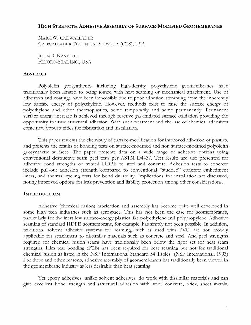
This improved adhesion and bonding of surface-modified material can literally be seen via scanning electron photomicrographs comparing the failure surfaces of tensile samples made with surface-modified and non-surface-modified rubber particles in an epoxy matrix. With non-surface-modified rubber particles, adhesion is so weak that the epoxy pulls away as the resin shrinks during curing. Surface-modified rubber particles, on the other hand, adhere tenaciously, so that the rubber particles tear during tensile testing, being well bonded to epoxy along particle boundaries (see Figure 2).
4
For the testing and discussion presented in this paper the terminology “surface-modification” refers to reactive gas-initiated surface-modification.
Non-surface-modified rubber particle surrounded by epoxy – reveals epoxy pulled away from rubber; no bonding at rubber/epoxy boundary; poor adhesion
Torn surface-modified rubber particle in epoxy – reveals bonding at rubber/epoxy boundary; tear occurring in material, not interface; excellent adhesion
Figure 2: Electron photomicrographs of tensile test failure surfaces showing difference between surface-modified and non-surface-modified rubber surfaces (after Bauman, 1995)
EXPERIMENTAL INVESTIGATIONS Methods and Materials In this test program we were interested in determining how the adhesive bond strengths of fluorine initiated surface-modified HDPE compared to HDPE geomembrane heat seaming. Could adhesively bonded HDPE give film tear bonds (FTB’s) ? Additionally we were interested in seeing whether glue-down strengths with steel could give FTB’s. We were also interested in how surface-modified HDPE adhesively bonded to concrete, how it adhered compared to concrete embedment liner, and how that bond held up through differential thermal expansion/contraction cycles.
All geomembranes tested were obtained as off-the-shelf stock of standard HDPE product in thicknesses ranging from 0.5 mm (20 mil) to 2.5 mm (100 mil). These were surface modified with to achieve an increased surface energy for adhesion testing.
A full range of production thicknesses was tested for geomembrane peel evaluations
because thicker materials deliver more stress for peel failure, and therefore more stress on the adhesive bond. Seventeen different adhesives were used in the testing program in order to qualify and assess a wide range of application conditions, properties, and pricing. A generic code for adhesives used and referred to in the table appears in Appendix A.
The different adhesives would have various industrial applications. For example novolac
epoxies have enhanced chemical resistance. Chemical resistance can also be provided by certain fillers. Some applications are less rigorous than others and can work with easier application methods such as an inexpensive single part adhesive. Further applications need the capability to
5
apply adhesives in damp or underwater situations. And still other applications require filled adhesives for a viscous coating which has a great deal of “grab” to facilitate thorough spreading with a trowel, sealing over entire surface areas. Most of the adhesives employed in this study were two part epoxies, combining resin and a hardener to cross link at reactive sites of the epoxy polymer. The adhesives have individual recommended mixing times, pot life, set times, handling times, and full cure times.
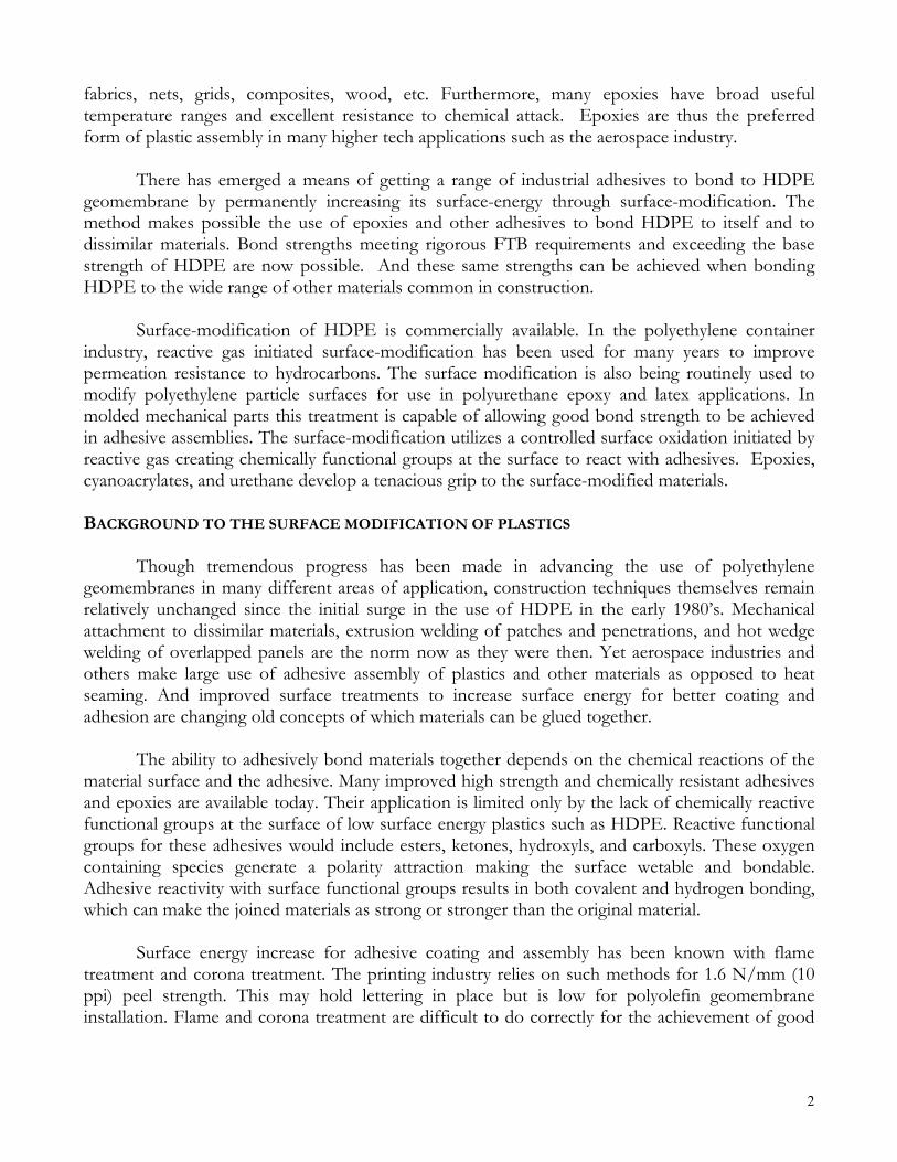
Figure 3. 2.5 mm surface-modified HDPE adhesively bonded to itself separating w/ FTB
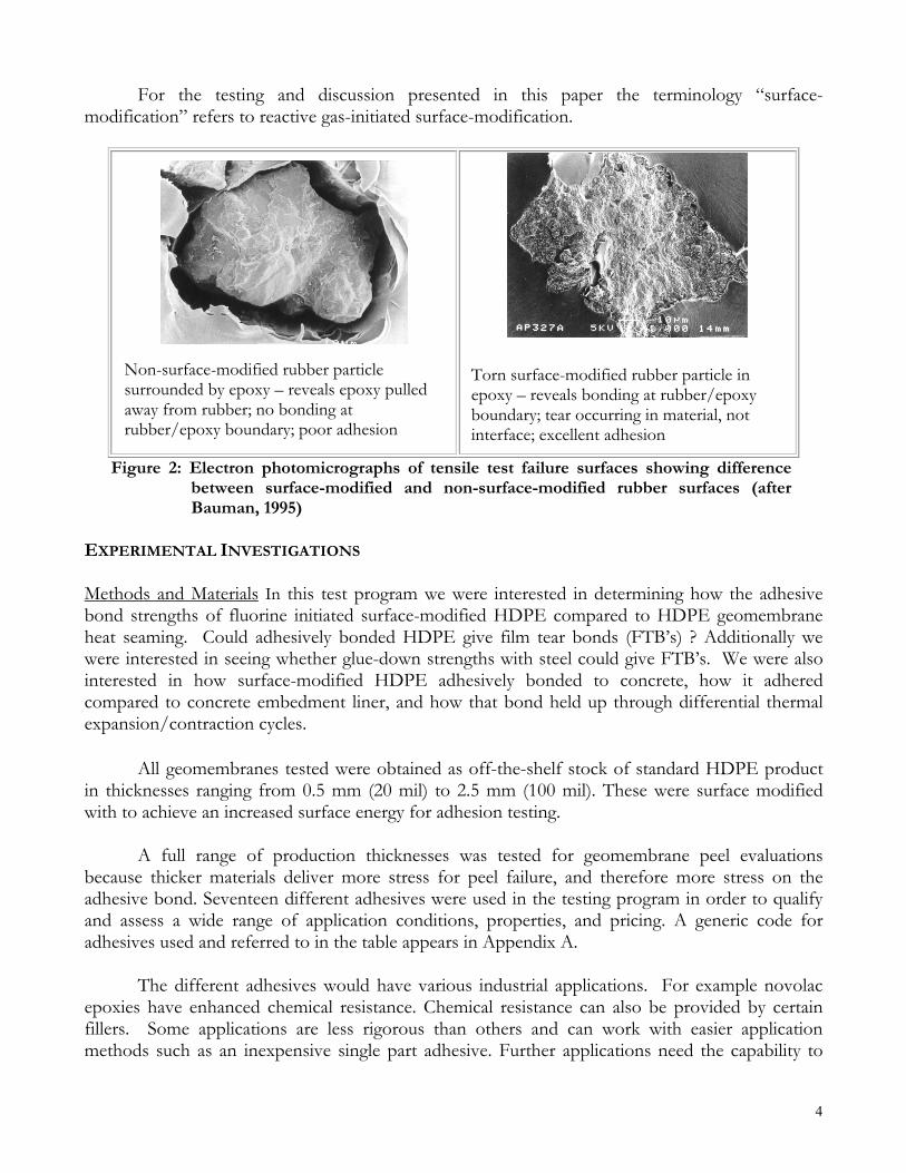
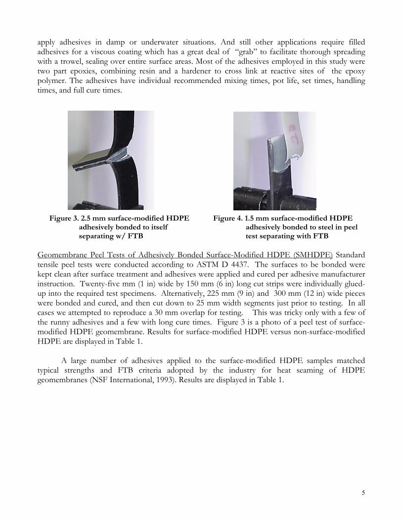
Figure 4. 1.5 mm surface-modified HDPE adhesively bonded to steel in peel test separating with FTB
Geomembrane Peel Tests of Adhesively Bonded Surface-Modified HDPE (SMHDPE) Standard tensile peel tests were conducted according to ASTM D 4437. The surfaces to be bonded were kept clean after surface treatment and adhesives were applied and cured per adhesive manufacturer instruction. Twenty-five mm (1 in) wide by 150 mm (6 in) long cut strips were individually glued-up into the required test specimens. Alternatively, 225 mm (9 in) and 300 mm (12 in) wide pieces were bonded and cured, and then cut down to 25 mm width segments just prior to testing. In all cases we attempted to reproduce a 30 mm overlap for testing. This was tricky only with a few of the runny adhesives and a few with long cure times. Figure 3 is a photo of a peel test of surface-modified HDPE geomembrane. Results for surface-modified HDPE versus non-surface-modified HDPE are displayed in Table 1.
A large number of adhesives applied to the surface-modified HDPE samples matched
typical strengths and FTB criteria adopted by the industry for heat seaming of HDPE geomembranes (NSF International, 1993). Results are displayed in Table 1.
6
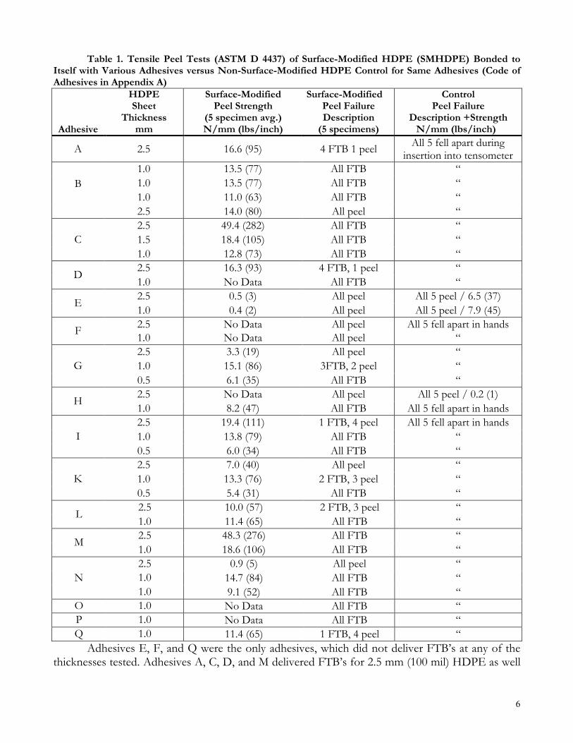
Table 1. Tensile Peel Tests (ASTM D 4437) of Surface-Modified HDPE (SMHDPE) Bonded to Itself with Various Adhesives versus Non-Surface-Modified HDPE Control for Same Adhesives (Code of Adhesives in Appendix A)
Adhesive
HDPE Sheet
Thickness mm
Surface-Modified Peel Strength
(5 specimen avg.) N/mm (lbs/inch)
Surface-Modified Peel Failure Description
(5 specimens)
Control Peel Failure
Description +Strength N/mm (lbs/inch)
A 2.5 16.6 (95) 4 FTB 1 peel All 5 fell apart during insertion into tensometer
1.0 13.5 (77) All FTB “ 1.0 13.5 (77) All FTB “ 1.0 11.0 (63) All FTB “
B
2.5 14.0 (80) All peel “ 2.5 49.4 (282) All FTB “ 1.5 18.4 (105) All FTB “ C 1.0 12.8 (73) All FTB “ 2.5 16.3 (93) 4 FTB, 1 peel “ D 1.0 No Data All FTB “ 2.5 0.5 (3) All peel All 5 peel / 6.5 (37) E 1.0 0.4 (2) All peel All 5 peel / 7.9 (45) 2.5 No Data All peel All 5 fell apart in hands F 1.0 No Data All peel “ 2.5 3.3 (19) All peel “ 1.0 15.1 (86) 3FTB, 2 peel “ G 0.5 6.1 (35) All FTB “ 2.5 No Data All peel All 5 peel / 0.2 (1) H 1.0 8.2 (47) All FTB All 5 fell apart in hands 2.5 19.4 (111) 1 FTB, 4 peel All 5 fell apart in hands 1.0 13.8 (79) All FTB “ I 0.5 6.0 (34) All FTB “ 2.5 7.0 (40) All peel “ 1.0 13.3 (76) 2 FTB, 3 peel “ K 0.5 5.4 (31) All FTB “ 2.5 10.0 (57) 2 FTB, 3 peel “ L 1.0 11.4 (65) All FTB “ 2.5 48.3 (276) All FTB “ M 1.0 18.6 (106) All FTB “ 2.5 0.9 (5) All peel “ 1.0 14.7 (84) All FTB “ N 1.0 9.1 (52) All FTB “
O 1.0 No Data All FTB “ P 1.0 No Data All FTB “ Q 1.0 11.4 (65) 1 FTB, 4 peel “
Adhesives E, F, and Q were the only adhesives, which did not deliver FTB’s at any of the thicknesses tested. Adhesives A, C, D, and M delivered FTB’s for 2.5 mm (100 mil) HDPE as well

7
as with 1.0 (40 mil) sheet. Adhesives B, G, H, K, L, N, and I gave FTB’s for the thinner sheet but not the 2.5 mm material. Adhesives O and P gave FTB’s with 1.0 mm material but were not tested with 2.5 mm material. The 3 adhesives which were claimed by the manufacturer as “good” for bonding standard HDPE (E, H, and I) did not do well without surface-modification, although adhesives E and H managed not to fall apart in our hands while being inserted into the tensometer. Interestingly, adhesive E actually performed worse with surface-modified HDPE than it did with standard HDPE, a possible indication of some different adhesive chemistry. Peel Tests of Surface-Modified HDPE (SMHDPE) Geomembrane Bonded to Steel Metal bond strength specimens were prepared using a strip of 3 mm (1/8 in) thick by 32 mm (1-1/4 in) wide by 130 mm (5 in) length of steel . A 50 mm (2 in) long bonding area was cleaned off each steel length using an abrasive grinding wheel. Grinding was continued until a uniform shiny surface of steel was exposed. Figure 4 shows a peel test of an HDPE/steel bonded interface. All metal/plastic-bonded samples were tested in 180° peel configuration due to the rigidity of steel forcing the plastic to bend completely back on itself. Tests with non-surface-modified geomembrane were not performed due to the inability of any of the adhesives to generate FTB’s on standard HDPE in the previous suite of geomembrane peel tests (Table 1).
Results of surface-modified HDPE bonded to steel bars are presented in Table 2. Again
film tear bonding took place except for the one case of thick (2.5mm) geomembrane using adhesive A. The failure plane in this case was on the steel. Bonding to the surface-modified HDPE was good, as also evidenced by the results for 2.5 mm membrane and adhesive A in Table 1.
Table 2. Surface-Modified HDPE (SMHDPE) Liner Bonded to Steel Plate in Tensile Peel Test
Adhesives
Sheet Thickness
mm
Peel (5 specimen avg.) N/mm (lbs./inch)
Failure Description
(5 specimens)
A 2.5 3.9 (22) All peel
F 1.5 17.3 (99) All FTB
G 1.0 11.9 (68) All FTB
H 1.0 11.9 (68) All FTB
J 1.5 13.0 (74) 4 FTB, 1 peel
K 1.0 9.6 (55) 2 FTB, 2peel Pullout Adhesion Tests in Concrete and Comparison with Concrete Embedment Liners For adhesion to concrete we devised a tensile “pullout” test suitable to evaluate the adhesive bonds as well as concrete embedment liner (CEL) cast into molded concrete bricks. CELs have “studs” or “ribs” with different profiles, thicknesses, and spacings, integrated onto HDPE geomembranes and jutting out from 8 to 1.5 mm so as to allow them to be cast into concrete as form fitting liners.
8
We performed stud-pullout evaluations on three types of embedment liner, two with differing stud profiles (CEL A and B) and one with continuous T-ribs (CEL C). We could find no standardized test information for testing strengths of CELs in concrete. Some manufacturers used single stud-pullout test results, while others had run expensive tests pressurizing the outside surface of large lined concrete pipe. But no standardized details were available. So we devised our own methodology and hardware.
We surface-modified the CEL samples and cast the three types of CELs into each of the
three types of ready mix. Wooden multi-section molds were used for this purpose. The mix was vibrated into place so as to fully surround and embed studs and to eliminate entrained air. The poured samples were cured for the requisite 28 days in a humid environment.
Concrete moldings were made using ready mix 20 MPa (3000 psi) compressive load
resistance as rated according to ASTM C 387 for a full 28 day cure. To add to the range we obtained some professional grade 35 MPa (5000 psi) concrete mix per ASTM C 387, as well as precision grout. The grout complied with ASTM C 1107 specifications for dry packed non-shrink grout in precise dimensional structured applications.
Once cured we gave the free surface of the molded blocks (opposite the surface with the
CEL-cast) a light grind with a 178 mm (7 in) diameter hand grinder and then grit-blasted it to remove laitance (loose mineral crust) and facilitate adhesion. We then bonded 1.5 mm surface-modified HDPE geomembrane to this prepped surface applying adhesive with a notched trowel, and left the opposing concrete face as-molded with embedment liner. We used a mica- filled epoxy previously employed in the geomembrane peel tests (Adhesive M). After sections of surface modified sheet were pressed into place, the adhesive was allowed to set at room temperature over night and then accelerated to complete cure by transferring to an air oven and being held at 54° C (130°F) for a week. In this manner each of our cast specimens provided two test values: one side with embedment liner and one side with a comparable adhesively bonded geomembrane.
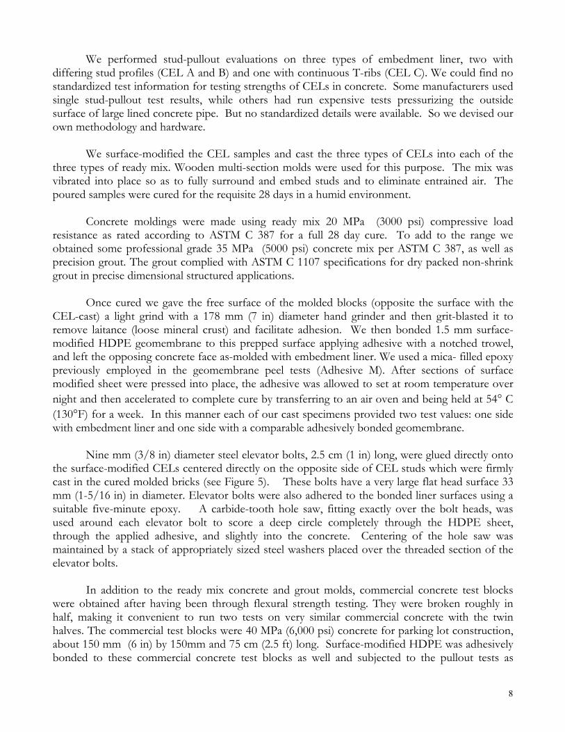
Nine mm (3/8 in) diameter steel elevator bolts, 2.5 cm (1 in) long, were glued directly onto
the surface-modified CELs centered directly on the opposite side of CEL studs which were firmly cast in the cured molded bricks (see Figure 5). These bolts have a very large flat head surface 33 mm (1-5/16 in) in diameter. Elevator bolts were also adhered to the bonded liner surfaces using a suitable five-minute epoxy. A carbide-tooth hole saw, fitting exactly over the bolt heads, was used around each elevator bolt to score a deep circle completely through the HDPE sheet, through the applied adhesive, and slightly into the concrete. Centering of the hole saw was maintained by a stack of appropriately sized steel washers placed over the threaded section of the elevator bolts.
In addition to the ready mix concrete and grout molds, commercial concrete test blocks
were obtained after having been through flexural strength testing. They were broken roughly in half, making it convenient to run two tests on very similar commercial concrete with the twin halves. The commercial test blocks were 40 MPa (6,000 psi) concrete for parking lot construction, about 150 mm (6 in) by 150mm and 75 cm (2.5 ft) long. Surface-modified HDPE was adhesively bonded to these commercial concrete test blocks as well and subjected to the pullout tests as
9
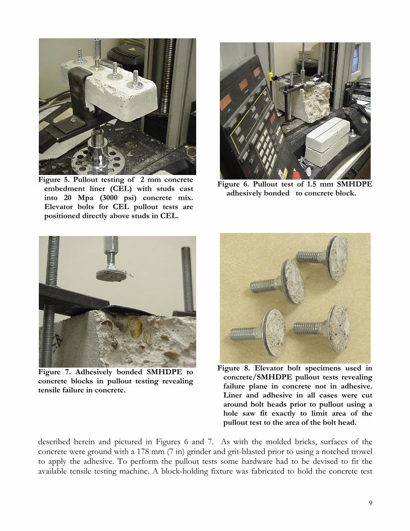
Figure 5. Pullout testing of 2 mm concrete embedment liner (CEL) with studs cast into 20 Mpa (3000 psi) concrete mix. Elevator bolts for CEL pullout tests are positioned directly above studs in CEL.
Figure 6. Pullout test of 1.5 mm SMHDPE adhesively bonded to concrete block.
Figure 7. Adhesively bonded SMHDPE to concrete blocks in pullout testing revealing tensile failure in concrete.
Figure 8. Elevator bolt specimens used in concrete/SMHDPE pullout tests revealing failure plane in concrete not in adhesive. Liner and adhesive in all cases were cut around bolt heads prior to pullout using a hole saw fit exactly to limit area of the pullout test to the area of the bolt head.
described herein and pictured in Figures 6 and 7. As with the molded bricks, surfaces of the concrete were ground with a 178 mm (7 in) grinder and grit-blasted prior to using a notched trowel to apply the adhesive. To perform the pullout tests some hardware had to be devised to fit the available tensile testing machine. A block-holding fixture was fabricated to hold the concrete test

10
bolt with liner was pulled off the concrete. Figures 5, 6, and 7 show tests in progress, while Figure 8 shows elevator bolts with liner pulled out of the concrete. Table 3 presents results for pullout testing pictured in Figures 5 – 8 and described above.
Table 3. Pullout Test Strengths of SMHDPE Geomembrane Adhesively Bonded to Concrete Compared with Pullout Strengths of Concrete Embedment Liners (CEL) Cast into Concrete
Adhesive
C KPa (psi)
Adhesive M
KPa (psi)
Adhesive R
KPa (psi)
CEL A
KPa (psi)
CEL B
KPa (psi)
CEL C*
KPa (psi) Ready Mix 20 MPa Concrete
- 1550 (225) - 250 (36) (676 N/stud)
730 (106) (649 N/stud)
-
Ready Mix 35 MPa Concrete
- 1630 (236) - 320 (47) (885 N/stud)
680 (99) (605 N/stud)
540 (78) (343
N/stud⋅cm) Commercial Test Block 40 MPa Concrete
2100 (304) 1860 (270) 1750 (254) - - -
Precision Grout - 3070 (445) - 350 (51)
(952 N/stud)
600 (87) (534 N/stud)
-
*Because CEL C featured a continuous T-shaped profile, which runs the length of the material, its stud strength was reported as N/stud⋅cm, calculating the load resistance along 1 cm of the T-profile. CEL’s A and B utilized single studs of differing shape and spacing with the elevator bolts for pullout tests positioned directly over a stud (see Fig 6).
The area of the elevator bolt heads established the area of the pullout test for the adhesively
bonded HDPE, for use in calculation of the load capacity of the liner/concrete connection. For pullout tests directly over concrete embedment studs, the proportion of embedment studs per unit area multiplied the tensometer load per stud for each of the 3-embedment liners considered in this study.
Tensometer loads for the elevator bolts centered over CEL studs were less than the loads for the bolts pulling up the adhesive bonded geomembrane. Failure planes in all cases for the adhesive bonded geomembrane were in the concrete. The fact that adhesive bonding covered a much larger area meant that corresponding pressure resistance was very much higher for the adhesive bonded surface-modified HDPE than for the CEL’s. This difference held up through thermal expansion/contraction cycling.
Expansion/Contraction Cycle Testing of SMHDPE Adhesive Bonds to Concrete Surface-modified HDPE was bonded to each of the twin halves of concrete blocks broken in commercial flex testing as described above. One of the halves with membrane and block was subjected to oven temperature cycling. The other half was set aside at room temperature. Three such broken block
11
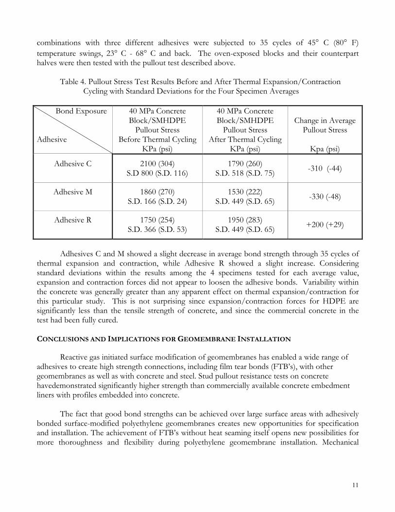
combinations with three different adhesives were subjected to 35 cycles of 45° C (80° F) temperature swings, 23° C - 68° C and back. The oven-exposed blocks and their counterpart halves were then tested with the pullout test described above.
Table 4. Pullout Stress Test Results Before and After Thermal Expansion/Contraction
Cycling with Standard Deviations for the Four Specimen Averages
Bond Exposure Adhesive
40 MPa Concrete Block/SMHDPE
Pullout Stress Before Thermal Cycling
KPa (psi)
40 MPa Concrete Block/SMHDPE
Pullout Stress After Thermal Cycling
KPa (psi)
Change in Average
Pullout Stress
Kpa (psi)
Adhesive C
2100 (304) S.D 800 (S.D. 116)
1790 (260) S.D. 518 (S.D. 75) -310 (-44)
Adhesive M
1860 (270) S.D. 166 (S.D. 24)
1530 (222) S.D. 449 (S.D. 65) -330 (-48)
Adhesive R
1750 (254) S.D. 366 (S.D. 53)
1950 (283) S.D. 449 (S.D. 65) +200 (+29)
Adhesives C and M showed a slight decrease in average bond strength through 35 cycles of
thermal expansion and contraction, while Adhesive R showed a slight increase. Considering standard deviations within the results among the 4 specimens tested for each average value, expansion and contraction forces did not appear to loosen the adhesive bonds. Variability within the concrete was generally greater than any apparent effect on thermal expansion/contraction for this particular study. This is not surprising since expansion/contraction forces for HDPE are significantly less than the tensile strength of concrete, and since the commercial concrete in the test had been fully cured. CONCLUSIONS AND IMPLICATIONS FOR GEOMEMBRANE INSTALLATION
Reactive gas initiated surface modification of geomembranes has enabled a wide range of adhesives to create high strength connections, including film tear bonds (FTB’s), with other geomembranes as well as with concrete and steel. Stud pullout resistance tests on concrete havedemonstrated significantly higher strength than commercially available concrete embedment liners with profiles embedded into concrete.
The fact that good bond strengths can be achieved over large surface areas with adhesively
bonded surface-modified polyethylene geomembranes creates new opportunities for specification and installation. The achievement of FTB’s without heat seaming itself opens new possibilities for more thoroughness and flexibility during polyethylene geomembrane installation. Mechanical

12
connections to dissimilar materials can be replaced or supplemented with sealants thoroughly applied to coat the material interfaces, provide secondary sealing, and prevent wrinkling.
Stud pullout specimens for the adhesive bonding studies presented here “pulled” concrete
out over the entire surface of the elevator bolt heads, wherever the bolts were glued to the liner samples. Adhesive sealants with barrier properties can thus introduce a secondary level of barrier action over a wide area in the joining of dissimilar materials. Using “trowelable” adhesives, e.g. those containing fillers for more viscous coatings, sealants can be applied between surfaces such as concrete and surface-modified HDPE geomembranes, with uniform bonding and protective sealing over a large area. Figures 9 and 10 show such procedure in a test case on a concrete pad at the top of an earthen slope, which was being lined with HDPE.
Surface-modification of polyolefins opens up options for installation of geomembranes
heretofore not possible. These include adhesive seaming of HDPE geomembranes using single sided and double sided tape to hold epoxies in place as is done in the chemical fusion of other less chemically resistant liners. Surface-modification also enables high strength supplemental or replacement connections to dissimilar materials such as concrete. It provides the option for self-installation and self-repair; the option to join materials together with high strength in wet environments using underwater rated epoxies; and the option for uniform adhesion of other geosynthetics to geomembrane surfaces, such as geonet and geotextile. Bonding need no longer be restricted to point locations such as extrusion weld beads, batten strips, and concrete embedment liner studs, but can take place over a wide area. Such options for improved performance, economics, and leakage liability protection for geomembrane installations are especially significant when one considers that they were not possible before with dissimilar materials and with polyolefin geomembranes like HDPE.
Figure 9. Troweling asphalt adhesive sealant
onto concrete berm surface prior to folding into place surface-modified white/black coextruded HDPE to cover concrete.
Figure 10. Surface-modified white/black co-
extruded HDPE placed over sealed concrete (Fig 9) with another panel deployed down sand-surfaced slope. Note difference in wrinkling between sealed and unsealed HDPE.
13
REFERENCES ASTM D 4437 (1988) “Standard Practice for Determining the Integrity of Field Seams Used in Joining Flexible Polymeric Sheet Geomembranes”, Annual Book of ASTM Standards, Vol. 04.09 Bauman, B. D. (1995) “Surface Modified Polymer Particles and Short, Chopped Fibers in Epoxies”, Society of Plastics Industry Epoxy Resin Formulators Div Meeting, Society of Plastics Industry (SPI), San Francisco, USA NSF International (1993) “Standard 54 – Flexible Membrane Liners”, NSF International, Ann Arbor, MI, USA pg 7,8,13 APPENDIX A GENERIC CODE OF ADHESIVES A- 100% Solids (i.e. no solvents) Epoxy Novolac B- 100% Solids Epoxy Novolac C- Ceramic Filled 100% Solids Epoxy Novolac D- 100% Solids Epoxy Novolac E- Structural Plastics Adhesive - claimed good for standard HDPE F- Lightly Flexibilized Epoxy G- Acrylic Polymer Epoxy H- Epoxy Resin Blend with Silicone - claimed good for standard HDPE I- Epoxy Prepolymer; claimed to work well for low surface energy substrates such
as HDPE J- Cyanoacrylate Adhesive K- Epoxy Resin Blend with Silicone
L- 100% Solids Epoxy Novolac M- Epoxy Novolac with Mica Filler N- Filled Epoxy Resin Recommended for Underwater Repair O- Five minute Metal/Concrete Epoxy P- Metal Filled Epoxy
Q- Kaolinite Filled Epoxy R- 100% Solids Epoxy Paste
ACKNOWLEDGEMENTS
The authors thank Fluoro-Seal, Inc., Houston, TX for providing surface-modified
geomembranes, and HTS Consultants, Inc., Houston, TX for providing lab facilities and testing assistance. Suppliers of adhesives include: 3M Cororation., Superior Environmental Products Inc., Epoxy Systems Inc, ITW Devcon, National Starch and Chemical Company, Permabond International. Division, J.B. Weld Company, Master Bond Inc., Nbond Adhesives International, Cytec Industries Inc., Cielcoat Inc., Locktite Corporation, and Power Poxy Adhesives Inc.