high-speed remote control of r&s sgma rf sources application note · r&s®sgma rf sources...
TRANSCRIPT

High-Speed Remote Control of R&S®SGMA RF Sources Application Note
Products:
| R&SSGT100A
| R&SSGS100A
This application note describes how to remotely control the R&S SGMA RF sources SGT100A and SGS100A with a special focus on their high-speed remote control capabilities via LAN based FAST Socket or FAST PCI Express (PCIe) connections which allow round trip setting times of only 100µs.
It therefore provides a brief introduction into the general remote control capabilities, explains the interaction of the different SW protocol layers and drivers, and in detail describes how to establish a high-speed remote control connection. Finally, a comparison of the measured setting time performance of the different remote control approaches is provided.
Note:
Please find the most up-to-date document on our homepage
This document is complemented by software. The software may be updated even if the version of the document remains unchanged
App
licat
ion
Not
e
C. N
euha
eusl
er
05.2
016-
1GP
107_
0E
Table of Contents
1GP107_0E Rohde & Schwarz High-Speed Remote Control of SGMA RF Sources 2
Table of Contents
1 Introduction ............................................................................ 5
2 Remote Control ...................................................................... 6
2.1 Interfaces ....................................................................................................... 6
2.1.1 LAN ................................................................................................................ 7
2.1.2 USB ................................................................................................................ 7
2.1.3 PCI Express (PCIe) ....................................................................................... 8
2.1.3.1 Overview ........................................................................................................ 8
2.1.3.2 SGT/SGS PCIe Interface .............................................................................. 9
2.1.3.3 Host Controller PCIe Interface .................................................................... 9
2.1.3.4 PCIe Interface HW Connection Setup ......................................................10
2.2 Protocol Layers ..........................................................................................11
2.2.1 Virtual Instruments Software Architecture (VISA) ..................................12
2.2.2 R&S Instrument Drivers .............................................................................13
2.3 Remote Connection Setup ........................................................................15
2.3.1 VISA Resource String ................................................................................15
3 High-Speed Remote Control ............................................... 17
3.1 Interfaces .....................................................................................................19
3.1.1 LAN ..............................................................................................................19
3.1.2 PCI Express (PCIe) .....................................................................................19
3.2 Protocol Layers ..........................................................................................20
3.2.1 R&S Instrument Drivers .............................................................................20
3.3 Remote Connection Setup and Configuration ........................................21
3.4 Setting Time Performance .........................................................................23
3.4.1 Definitions ...................................................................................................23
3.4.1.1 Setting Time Types ....................................................................................23
3.4.1.2 Setting Time Impacts .................................................................................24
3.4.2 Comparison .................................................................................................25
4 Abbreviations ....................................................................... 28
5 References ............................................................................ 29
6 Appendix ............................................................................... 30
Table of Contents
1GP107_0E Rohde & Schwarz High-Speed Remote Control of SGMA RF Sources 3
6.1 SGMA Speed Test Excel Worksheet ........................................................30
6.1.1 Prerequisites ...............................................................................................31
6.1.2 Speed Test Performance ...........................................................................31
6.1.3 Speed Test Detailed Results .....................................................................33
6.2 Code Examples ...........................................................................................33
7 Ordering Information ........................................................... 34
Interfaces
1GP107_0E Rohde & Schwarz High-Speed Remote Control of SGMA RF Sources 4
The following abbreviations are used in this application note for Rohde & Schwarz products:
The R&S®SGT100A vector RF source is referred to as SGT
The R&S®SGS100A RF source is referred to as SGS
The R&S®SGMA100A RF (vector) source family is referred to as SGMA
The PCI Express®/PCIe
® logo and name are trademarks for PCI-SIG in the United
States and/or other countries.
Microsoft® Windows and Microsoft
® Excel are registered trademarks of Microsoft
Corporation in the United States and/or other countries.
LabVIEW™ logo and name are registered trademarks of National Instruments Corporation in the United States and/or other countries.

Introduction
Interfaces
1GP107_0E Rohde & Schwarz High-Speed Remote Control of SGMA RF Sources 5
1 Introduction State of the art Automated Test Equipment (ATE) must guarantee consistent and highly accurate testing combined with a maximum test speed. Only this kind of test equipment allows efficient testing with an optimized throughput and high yield.
The R&S SGMA (vector) RF sources have been designed to exactly fit these needs. They offer highly accurate RF signals (CW and/or vector modulated) especially tailored for RF ATE systems in combination with a minimized remote control setting time.
This application note describes how to remotely control the R&S SGMA RF sources SGT100A and SGS100A with a special focus on their high-speed remote control capabilities via LAN based FAST Socket or FAST PCI Express (PCIe) connections which allow round trip setting times of only 100µs. It therefore provides a brief introduction into the general remote control capabilities, explains the interaction of the different SW protocol layers and drivers, and in detail describes how to establish a high-speed remote control connection. Finally, a comparison of the measured setting time performance of the different remote control approaches is provided.
Refer to the SGMA user manuals [1] and [2] for further remote control basics and the SGMA specific SCPI remote control commands.
Remote Control
Interfaces
1GP107_0E Rohde & Schwarz High-Speed Remote Control of SGMA RF Sources 6
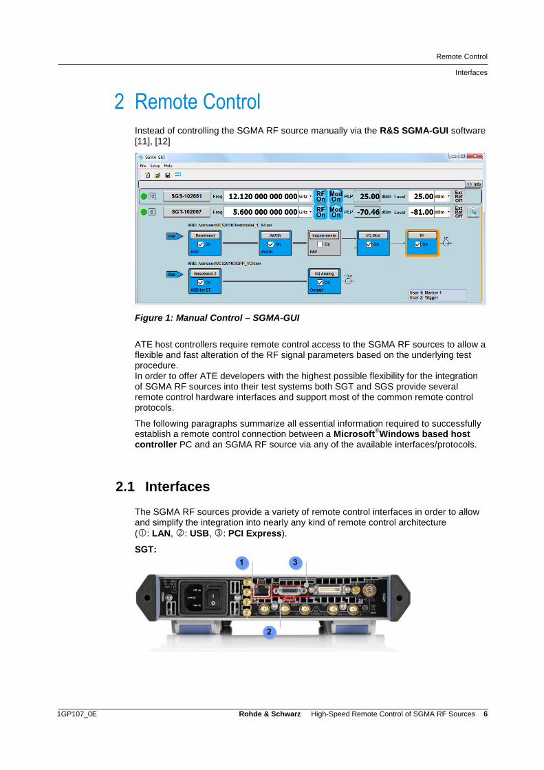
2 Remote Control Instead of controlling the SGMA RF source manually via the R&S SGMA-GUI software [11], [12]
Figure 1: Manual Control – SGMA-GUI
ATE host controllers require remote control access to the SGMA RF sources to allow a flexible and fast alteration of the RF signal parameters based on the underlying test procedure. In order to offer ATE developers with the highest possible flexibility for the integration of SGMA RF sources into their test systems both SGT and SGS provide several remote control hardware interfaces and support most of the common remote control protocols.
The following paragraphs summarize all essential information required to successfully establish a remote control connection between a Microsoft
®Windows based host
controller PC and an SGMA RF source via any of the available interfaces/protocols.
2.1 Interfaces
The SGMA RF sources provide a variety of remote control interfaces in order to allow and simplify the integration into nearly any kind of remote control architecture
(: LAN, : USB, : PCI Express).
SGT:
Remote Control
Interfaces
1GP107_0E Rohde & Schwarz High-Speed Remote Control of SGMA RF Sources 7
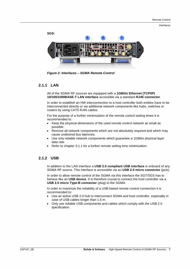
SGS:
Figure 2: Interfaces – SGMA Remote Control
2.1.1 LAN
All of the SGMA RF sources are equipped with a 1GBit/s Ethernet (TCP/IP) 10/100/1000BASE-T LAN interface accessible via a standard RJ45 connector.
In order to establish an HW interconnection to a host controller both entities have to be interconnected directly or via additional network components like hubs, switches or routers by using CAT5 RJ45 cables.
For the purpose of a further minimization of the remote control setting times it is recommended to:
Keep the physical dimensions of the used remote control network as small as possible.
Remove all network components which are not absolutely required and which may cause undesired bus latencies.
Use only reliable network components which guarantee a 1GBit/s physical layer data rate.
Refer to chapter 3.1.1 for a further remote setting time minimization.
2.1.2 USB
In addition to the LAN interface a USB 2.0 compliant USB interface is onboard of any SGMA RF source. This interface is accessible via an USB 2.0 micro connector (jack).
In order to allow remote control of the SGMA via this interface the SGT/SGS has to behave like an USB device. It is therefore crucial to connect the host controller via a USB 2.0 micro Type-B connector (plug) to the SGMA.
In order to maximize the reliability of a USB based remote control connection it is recommended to:
Use an active USB 2.0 hub to interconnect SGMA and host controller, especially in case of USB cables longer than 1.5 m.
Only use reliable USB components and cables which comply with the USB 2.0 specification.

Remote Control
Interfaces
1GP107_0E Rohde & Schwarz High-Speed Remote Control of SGMA RF Sources 8
2.1.3 PCI Express (PCIe)
Since PCI Express (PCIe) interfaces are not as widely available as LAN or USB interfaces for remote control applications the following paragraphs are intended to provide a brief overview about PCI Express in general and its implementation on the SGMA RF sources and the host controller with a special focus on the HW interconnection setup.
2.1.3.1 Overview
Formed in 1992, the Peripheral Component Interconnect Special Interest Group (PCI-SIG) with currently nearly 800 members is committed to the development and enhancement of the PCI specification(s) as open industry standards. The Peripheral Component Interconnect (PCI) bus which was first introduced in the early 1990s provides I/O functionality for any kind of computer (e.g. servers, PCs workstations and also mobile devices). It is also a standard to transfer data between a CPU and its peripherals. Although PCI has enjoyed great success, it faces a series of challenges, including bandwidth limitations, lack of real-time data transfer services and others. To overcome these challenges PCI Express (PCIe), an evolutionary version of PCI, was introduced in 2004. Today, most PCs are shipped with a combination of PCI and PCI Express slots. PCI Express maintains the PCI software usage model and replaces the parallel physical bus with a high-speed serial bus, composed of point-to-point serial connections between two devices. It offers a scalable bandwidth performance based on the number of signal Lanes implemented on the PCI Express interconnects. The following figure highlights the used PCIe terminology:
Figure 3: PCI Express – Interconnection Terminology
The main features and advantages of PCIe are:
High-speed point-to-point (serial) connection which results in viewer pins compared to the predecessor PCI with its parallel interface architecture
Dual simplex connection (independent differential signals from/to the host device)
Scalable: x1, x2, x4, x8, x12, x16, x32 lanes
Packet based transaction protocol
2.5 (Rev. 1.x) ... 16.0 GT/s (Rev. 4.0)
The PCIe technology is constantly evolved and improved. As of 2015 the PCIe specification has reached version 4 (draft only). The following table provides an
PCI Express Device A (Host)
PCI Express Device B (Target)
Lane
SignalLink
Remote Control
Interfaces
1GP107_0E Rohde & Schwarz High-Speed Remote Control of SGMA RF Sources 9
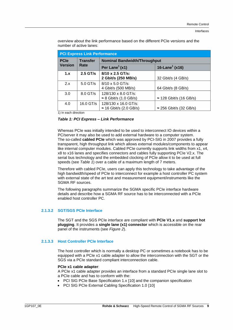
overview about the link performance based on the different PCIe versions and the number of active lanes:
PCI Express Link Performance
PCIe Version
Transfer Rate
Nominal Bandwidth/Throughput
Per Lane1 (x1) 16-Lane
1 (x16)
1.x 2.5 GT/s 8/10 x 2.5 GT/s: 2 Gbit/s (250 MB/s)
32 Gbit/s (4 GB/s)
2.x 5.0 GT/s 8/10 x 5.0 GT/s: 4 Gbit/s (500 MB/s)
64 Gbit/s (8 GB/s)
3.0 8.0 GT/s 128/130 x 8.0 GT/s: ≈ 8 Gbit/s (1.0 GB/s)
≈ 128 Gbit/s (16 GB/s)
4.0 16.0 GT/s 128/130 x 16.0 GT/s: ≈ 16 Gbit/s (2.0 GB/s)
≈ 256 Gbit/s (32 GB/s)
1) In each direction
Table 1: PCI Express – Link Performance
Whereas PCIe was initially intended to be used to interconnect IO devices within a PC/server it may also be used to add external hardware to a computer system. The so-called cabled PCIe which was approved by PCI-SIG in 2007 provides a fully transparent, high throughput link which allows external modules/components to appear like internal computer modules. Cabled PCIe currently supports link widths from x1, x4, x8 to x16 lanes and specifies connectors and cables fully supporting PCIe V2.x. The serial bus technology and the embedded clocking of PCIe allow it to be used at full speeds (see Table 1) over a cable of a maximum length of 7 meters.
Therefore with cabled PCIe, users can apply this technology to take advantage of the high bandwidth/speed of PCIe to interconnect for example a host controller PC system with external state of the art test and measurement equipment/instruments like the SGMA RF sources.
The following paragraphs summarize the SGMA specific PCIe interface hardware details and describe how a SGMA RF source has to be interconnected with a PCIe enabled host controller PC.
2.1.3.2 SGT/SGS PCIe Interface
The SGT and the SGS PCIe interface are compliant with PCIe V1.x and support hot plugging. It provides a single lane (x1) connector which is accessible on the rear panel of the instruments (see Figure 2).
2.1.3.3 Host Controller PCIe Interface
The host controller which is normally a desktop PC or sometimes a notebook has to be equipped with a PCIe x1 cable adapter to allow the interconnection with the SGT or the SGS via a PCIe standard compliant interconnection cable.
PCIe x1 cable adapter: A PCIe x1 cable adapter provides an interface from a standard PCIe single lane slot to a PCIe cable and has to conform with the:
PCI SIG PCIe Base Specification 1.x [10] and the companion specification
PCI SIG PCIe External Cabling Specification 1.0 [10]

Remote Control
Interfaces
1GP107_0E Rohde & Schwarz High-Speed Remote Control of SGMA RF Sources 10
These adapters which are available from different vendors are mostly completely transparent to PCIe but include signal repeating functionality, allowing cables up to 7 meters in length to be reliably used. Nearly all of them do not require any kind of software (adapter card specific drivers) for operation. On desktop PCs the host cable adapter has to be installed in a PCIe expansion slot. Notebooks with available Express Card slots can be extended by an Express Card cable adapter:
Figure 4: PCI Express – PCIe x1 Cable Adapters
The following paragraph provides a guideline how to establish a HW interconnection between an SGMA device and a host controller.
2.1.3.4 PCIe Interface HW Connection Setup
In the following it is assumed that the host controller PC does not provide PCIe hot-plugging capabilities and that both the SGMA RF source and the host controller are switched off.
1. SGS only: It has to be evaluated prior to the PCIe connection setup via the SGMA-GUI if the PCIe interface is configured to the compelling interface mode ‘Endpoint’ (Default mode): Setup → Maintenance → Operation → PCIe Interface Mode.
2. At first, an interconnection between both entities has to be established by using a suitable PCIe single lane cable.
Figure 5: PCI Express – PCIe x1 Cable
3. Power-on the SGMA RF source and wait until the power on/standby button on the
front side of the instrument becomes green (permanent non-blinking) which indicates that the startup process has been finished and the instrument is thus ready for operation.
4. Finally switch on the host controller PC.

Remote Control
Protocol Layers
1GP107_0E Rohde & Schwarz High-Speed Remote Control of SGMA RF Sources 11
Perform the steps described above in reverse order to shut down the SGMA source and an interconnected host controller.
To maximize the reliability of a PCIe based remote control connection it is essential to notice that most of the shelf host controller PCs do not provide PCIe hot plugging capabilities. It is therefore strictly recommended:
Not to interconnect the SGMA PCIe interface with the cable adapter during operation.
Not to switch off an SGMA RF source if it is interconnected to an operating host controller via the PCIe interface.
2.2 Protocol Layers
Remote control interfaces come to life only with the availability of the related software protocol stacks. They enable the host control to interact with the SGMA RF sources in a well-defined manner. The SGMA RF sources offer a bunch of different protocols for a remote control interaction fitting nearly any ATE test system requirements and/or preferences of the ATE developer(s):
Figure 6: Protocol Layers – Overview
The following paragraphs intend to explain this protocol layer overview and to properly highlighting the different remote control approaches (VISA or Instrument-driver based). Additionally some light is shed on the required libraries, the drivers and their interaction.
Application SW
R&S SGMA Instrument Driver
VISA Lib
Socket
PCIe Ctrl. Lib
VXI-11HiSLIP USBTMC
Socket Ctrl. Lib
LANPCIexpress
LANPCIexpress
Kernel Driver
SCPI Channel/Parser/Database
Org. Layer
Hardware
SCPI SCPIBinary
R&
S®S
GM
AH
os
t C
on
tro
lle
r
R. Sock. SocketProprietary
Ethernet
Ethernet
USB
USB
SCPIBinary
FAST STD FAST STD

Remote Control
Protocol Layers
1GP107_0E Rohde & Schwarz High-Speed Remote Control of SGMA RF Sources 12
2.2.1 Virtual Instruments Software Architecture (VISA)
VISA, a standardized software library, acts as a kind of I/O HW abstraction layer maintained and evolved by the IVI foundation. It allows simplified remote control communication via a variety of interfaces and protocols. It is available free of charge from R&S [15] or may be purchased from other vendors.
The VISA library enables the ATE developer to access the SGMA RF sources via the LAN and the USB interface by using the Socket, HiSLIP, VXI-11 and USBTMC protocol:
Figure 7: VISA based SGMA remote control – Protocol Layers
For this reason the VISA library exports functions which allow ATE developers to:
establish a remote control connection to a certain instrument based on a unique interface/protocol specific identifier, the so-called ‘VISA Resource String’ (see chapter 2.3 for further details on the connection setup)
send/write instrument specific SCPI commands (see [1] and [2]) to the SGMA device under control
receive/read data from the test instrument
maintain and parameterize the remote connection (e.g. timeouts)
The following table provides a first overview and informs about the required SW libraries which have to be installed on the host controller PC to support VISA based remote control via a certain interface and protocol:
SGMA VISA based Remote Control – Libraries
Interface Protocol Libraries
HW Abstraction
LAN (Ethernet)
TCP/IP VXI-11 VISA
TCP/IP HiSLIP
TCPIP Socket
USB USBTMC
Table 2: VISA based SGMA remote control – Libraries
Application SW
VISA Lib
Socket VXI-11HiSLIP USBTMC
LAN
LAN
Kernel Driver
SCPI Channel/Parser/Database
Org. Layer
Hardware
SCPI
R&
S®S
GM
AH
os
t C
on
tro
lle
r
USB
USB
SCPI

Remote Control
Protocol Layers
1GP107_0E Rohde & Schwarz High-Speed Remote Control of SGMA RF Sources 13
2.2.2 R&S Instrument Drivers
R&S Instrument Drivers may be used optionally in combination with the VISA library. Instrument drivers are the means of choice if ATE developers are not interested in plain SCPI-command-based remote control but prefer to use more abstract functions/methods in combination with online help functions. The R&S instrument drivers can easily be integrated into various Integrated Development Environments (IDE).
R&S offers instrument drivers for all SGMA RF sources free of charge:
Instrument Driver based SGMA control – Instrument Drivers
Driver Title SGT [13] SGS [14]
VXI Plug&Play x64 rssgt-vxipnp_x64 rssgs-vxipnp_x64
VXI Plug&Play x86 rssgt-vxipnp_x86 rssgs-vxipnp_x86
LabWindows/CVI rssgt-cvi1 rssgs-cvi
1
Linux/OSX
LabVIEW 2010 x86 rssgt-lv_x86 rssgs-lv_x86
1) Driver source code which may be integrated and compiled with different IDEs
Table 3: Instrument Drivers based SGMA control – Instrument Drivers
Related application notes and programming language specific application examples are available as well [3], [4], [5], [6], [7].
The SGMA instrument drivers in combination with the VISA library enable the ATE software developer to access the SGMA RF sources via all available HW interfaces by using the Socket, HiSLIP, VXI-11, USBTMC and an R&S proprietary PCIe protocol:
Figure 8: Instrument Drivers based SGMA control – Protocol Layers
As illustrated in the above figure SGMA instrument drivers not only encapsulate SCPI commands but also have to take care about the driver and protocol specific I/O hardware abstraction layer. LAN based interconnections via HiSLIP, VXI-11 or USBTMC are setup using the underlying VISA library. LAN based Socket connections will either be established via the VISA library (LabVIEW) or by using the R&S Socket Controller library as an I/O
Application SW
R&S SGMA Instrument Driver
VISA Lib PCIe Ctrl. Lib
VXI-11HiSLIP USBTMC
Socket Ctrl. Lib
LANPCIexpress
LANPCIexpress
Kernel Driver
SCPI Channel/Parser/Database
Org. Layer
Hardware
SCPI SCPI
R&
S®S
GM
AH
os
t C
on
tro
lle
r
SocketProprietary
USB
USB
SCPI
Socket
Remote Control
Protocol Layers
1GP107_0E Rohde & Schwarz High-Speed Remote Control of SGMA RF Sources 14
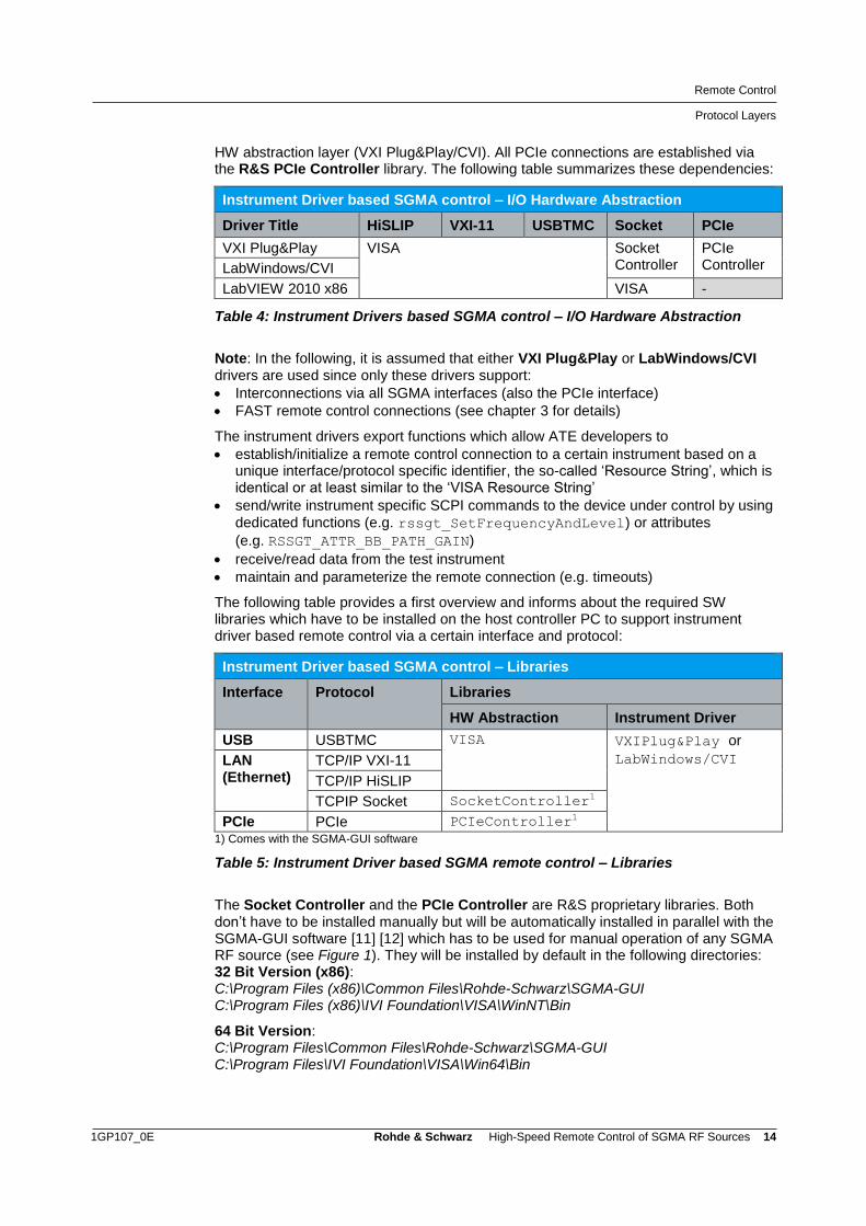
HW abstraction layer (VXI Plug&Play/CVI). All PCIe connections are established via the R&S PCIe Controller library. The following table summarizes these dependencies:
Instrument Driver based SGMA control – I/O Hardware Abstraction
Driver Title HiSLIP VXI-11 USBTMC Socket PCIe
VXI Plug&Play VISA Socket Controller
PCIe Controller LabWindows/CVI
LabVIEW 2010 x86 VISA -
Table 4: Instrument Drivers based SGMA control – I/O Hardware Abstraction
Note: In the following, it is assumed that either VXI Plug&Play or LabWindows/CVI drivers are used since only these drivers support:
Interconnections via all SGMA interfaces (also the PCIe interface)
FAST remote control connections (see chapter 3 for details)
The instrument drivers export functions which allow ATE developers to
establish/initialize a remote control connection to a certain instrument based on a unique interface/protocol specific identifier, the so-called ‘Resource String’, which is identical or at least similar to the ‘VISA Resource String’
send/write instrument specific SCPI commands to the device under control by using
dedicated functions (e.g. rssgt_SetFrequencyAndLevel) or attributes
(e.g. RSSGT_ATTR_BB_PATH_GAIN)
receive/read data from the test instrument
maintain and parameterize the remote connection (e.g. timeouts)
The following table provides a first overview and informs about the required SW libraries which have to be installed on the host controller PC to support instrument driver based remote control via a certain interface and protocol:
Instrument Driver based SGMA control – Libraries
Interface Protocol Libraries
HW Abstraction Instrument Driver
USB USBTMC VISA VXIPlug&Play or
LabWindows/CVI LAN (Ethernet)
TCP/IP VXI-11
TCP/IP HiSLIP
TCPIP Socket SocketController1
PCIe PCIe PCIeController1
1) Comes with the SGMA-GUI software
Table 5: Instrument Driver based SGMA remote control – Libraries
The Socket Controller and the PCIe Controller are R&S proprietary libraries. Both don’t have to be installed manually but will be automatically installed in parallel with the SGMA-GUI software [11] [12] which has to be used for manual operation of any SGMA RF source (see Figure 1). They will be installed by default in the following directories: 32 Bit Version (x86): C:\Program Files (x86)\Common Files\Rohde-Schwarz\SGMA-GUI C:\Program Files (x86)\IVI Foundation\VISA\WinNT\Bin
64 Bit Version: C:\Program Files\Common Files\Rohde-Schwarz\SGMA-GUI C:\Program Files\IVI Foundation\VISA\Win64\Bin

Remote Control
Remote Connection Setup
1GP107_0E Rohde & Schwarz High-Speed Remote Control of SGMA RF Sources 15
2.3 Remote Connection Setup
This chapter summarizes relevant aspects for properly setting up a remote control interconnection between an SGMA RF source and a host controller PC.
In the following it is assumed that:
the HW interconnection to a certain remote control interface was properly established and
all relevant and latest libraries/drivers are installed on the host controller.
2.3.1 VISA Resource String
To open a remote control session to a certain SGMA device via the:
VISA function viOpen or the
Instrument driver functions rssgt_init or rssgs_init
an address string has to be passed to these functions which uniquely identifies the device/resource. The resource strings supported by a certain SGMA RF source may be retrieved via the SGMA-GUI software: SGS/SGT → Setup → Remote:
Figure 9: Remote Connection Setup – VISA Resource Strings (SGT)
In the following, the resource string syntax is described in detail (SGS/SGT resource strings). Optional string segments are shown in square brackets: VXI-11 resource string:
TCPIP[board]::host address[::LAN device name][::INSTR]
board Host controller LAN interface index. Only relevant in case of
several installed LAN interfaces. Default: 0 host address Assigned IP address or hostname (e.g. rssgt100a102661) LAN device name inst0 in case of VXI11
Example: TCPIP::rssgt100a102661::inst0::INSTR
Remote Control
Remote Connection Setup
1GP107_0E Rohde & Schwarz High-Speed Remote Control of SGMA RF Sources 16
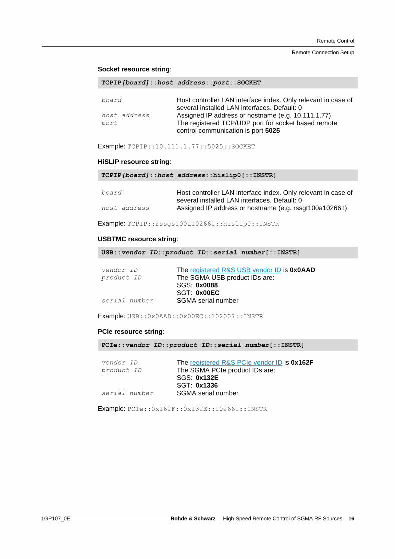
Socket resource string:
TCPIP[board]::host address::port::SOCKET
board Host controller LAN interface index. Only relevant in case of
several installed LAN interfaces. Default: 0 host address Assigned IP address or hostname (e.g. 10.111.1.77) port The registered TCP/UDP port for socket based remote
control communication is port 5025
Example: TCPIP::10.111.1.77::5025::SOCKET
HiSLIP resource string:
TCPIP[board]::host address::hislip0[::INSTR]
board Host controller LAN interface index. Only relevant in case of
several installed LAN interfaces. Default: 0 host address Assigned IP address or hostname (e.g. rssgt100a102661)
Example: TCPIP::rssgs100a102661::hislip0::INSTR
USBTMC resource string:
USB::vendor ID::product ID::serial number[::INSTR]
vendor ID The registered R&S USB vendor ID is 0x0AAD product ID The SGMA USB product IDs are:
SGS: 0x0088 SGT: 0x00EC
serial number SGMA serial number
Example: USB::0x0AAD::0x00EC::102007::INSTR
PCIe resource string:
PCIe::vendor ID::product ID::serial number[::INSTR]
vendor ID The registered R&S PCIe vendor ID is 0x162F product ID The SGMA PCIe product IDs are:
SGS: 0x132E SGT: 0x1336
serial number SGMA serial number
Example: PCIe::0x162F::0x132E::102661::INSTR

High-Speed Remote Control
Remote Connection Setup
1GP107_0E Rohde & Schwarz High-Speed Remote Control of SGMA RF Sources 17
3 High-Speed Remote Control The remote control setting speed of nearly all R&S instruments and especially of the SGMA RF sources is fully sufficient for most standard test applications in R&D.
Nevertheless, in case of demanding test applications which require a high test throughput (e.g. extensive characterization tests or tests performed in a production line) a further reduction of the overall test time per DUT in the end leads to an earlier time to market and will thus result in significant financial savings and offers a noticeable competitive advantage. It has to be considered in this context that even setting time reductions of only 100 µs per remote control command may sum up over all commands per test run, the number of tested devices and all parallel running test systems to total test time savings per day of several minutes up to hours.
Therefore R&S has significantly improved the efficiency of the used algorithms and the remote control setting time of the SGMA RF sources. These improvements resulted in a new remote control mode for the SGMA RF sources, the so-called FAST Mode, which is part of the SGMA firmware by default (no additional option required). It allows R&S to increase the setting speed for commands which are used frequently and repeatedly in common test procedures by a factor of up to 8 in comparison with a standard remote control LAN connection (VXI11). In principle, this significant increase in remote control performance is achieved by an optimized transfer of the control commands. The standard/legacy remote control mode (see chapter 2) is based on a sent SCPI string which has to be intensively parsed and transformed into the required HW adjustments by the controlled instrument. The FAST mode in contrast is based on a much more hardware related (memory mapped) approach which allows broadly speaking direct access of the SGMA RF source to the memory (where the command resides) of the host controller which allows bypassing of time consuming protocol layers (e.g. the SCPI parser).
To benefit from these remote setting speed improvements only some prerequisites have to be fulfilled:
the remote control connection has to be established via LAN Socket or via PCIe
VXI Plug&Play or LabWindows/CVI instrument drivers have to be used
It has to be considered also that the FAST mode is focusing on those parameters/functions which are of major interest for high-speed ATE applications. The following table provides an overview about the operations which are currently supported by the FAST mode of SGT and SGS. Just for reference, also the related SCPI commands are shown which have to be sent to the SGMA RF source instead if the standard mode is used:
High-Speed Remote Control – Operations
Operation Description Supported
SGT SGS
RF Frequency Sets the RF frequency at the RF output connector
[:SOURce]:FREQuency[:CW|FIXed] <Cw>1
yes yes
RF Level Sets the RF level at the RF output connector
[:SOURce]:POWer[:LEVel][:IMMediate] [:AMPLitude] <Amplitude>
1
yes yes

High-Speed Remote Control
Remote Connection Setup
1GP107_0E Rohde & Schwarz High-Speed Remote Control of SGMA RF Sources 18
High-Speed Remote Control – Operations
Operation Description Supported
SGT SGS
RF State Activates/ deactivates the RF output
:OUTPut[:STATe]:PON <Pon>1
yes yes
Modulator State Switches the I/Q modulation on and off
[:SOURce]:IQ:STATe <State>1
yes yes
Wideband State Selects optimized settings for wideband modulation signals
[:SOURce]:IQ:WBSTate <State>
yes yes
Baseband Trigger Executes a baseband (ARB) trigger
[:SOURce<hw>]:BB:ARBitrary:TRIGger:EXECute1
yes n.a.
Digital Attenuation Sets a relative attenuation value for the baseband signal
[:SOURce]:POWer:ATTenuation:DIGital <AttDigital>
1
yes n.a.
Next Segment Triggers a switchover to the subsequent segment in a multi segment ARB waveform
[:SOURce<hw>]:BB:ARBitrary:WSEGment:NEXT:EXECute
1
yes n.a.
Delib. Segment Deliberately selects the segment of a multi segment ARB waveform to be output
[:SOURce<hw>]:BB:ARBitrary:WSEGment:NEXT <Next>
1
yes n.a.
Frequency Offset Sets the frequency offset for the baseband signal (relative to the RF frequency)
[:SOURce]:BB:FOFFset <Foffset>1
yes n.a.
Phase Offset Sets the phase offset for the baseband signal
[:SOURce]:BB:POFFset <Phoffset>1
yes n.a.
1) Corresponding SCPI command. Optional string segments are shown in square brackets.
Table 6: High-Speed Remote Control – Operations
Further details regarding this new remote control approach and how to establish this kind of high-speed remote control connection will be discussed in the following paragraphs.

High-Speed Remote Control
Interfaces
1GP107_0E Rohde & Schwarz High-Speed Remote Control of SGMA RF Sources 19
3.1 Interfaces
The SGMA RF sources provide a variety of remote control interfaces to allow and simplify the integration into nearly any kind of remote control architecture. Two of these interfaces (: LAN, and : PCI Express, see Figure 2) support the FAST Mode.
3.1.1 LAN
All of the SGMA RF sources are equipped with a 1GBit/s Ethernet (TCP/IP) 10/100/1000BASE-T LAN interface accessible via a standard RJ45 connector.
To establish an HW interconnection to a host controller both entities have to be interconnected directly or, if indispensable, via additional network components like hubs or switches by using CAT5 RJ45 cables.
To minimize the remote control setting times and thus to fully benefit from the FAST mode setting speed advantages, the general guidelines for LAN based remote control interconnections apply (see chapter 2.1.1) but have to be extended by the following requirements/recommendations:
Only Ethernet layer 2 network components (hubs or switches) must be used if that. No layer 3 or 4 TCP/IP routers are allowed in general.
For further setting speed optimizations of < 100 µs, one has to consider the performance of the used host controller network interface card. It may be worth adding an additional high performance network adapter which allows to optimize certain interface properties (e.g. disabling of interrupt coalescing).
3.1.2 PCI Express (PCIe)
The SGT and the SGS PCIe interface are compliant with PCIe V1.x and support hot plugging. It provides a single lane (x1) connector which is accessible on the rear panel of the instruments (see Figure 2).
To maximize the reliability of a PCIe based remote control connection the guidelines for PCIe based remote control interconnections apply (see chapter 2.1.3.4).
For further information about the PCIe interface, see chapter 2.1.3.

High-Speed Remote Control
Protocol Layers
1GP107_0E Rohde & Schwarz High-Speed Remote Control of SGMA RF Sources 20
3.2 Protocol Layers
Unlike standard remote control operations (see chapter 2.2) which use instrument drivers optionally in parallel with the VISA library, R&S VXI Plug&Play or LabWindows/CVI Instrument Drivers are compelling for FAST Socket and FAST PCIe protocol based remote control connections. The VISA based hardware abstraction layer is not at all required for this kind of connection.
3.2.1 R&S Instrument Drivers
Only the R&S VXI Plug&Play and the LabWindows/CVI Instrument Drivers allow access to the Socket Controller and the PCIe Controller library which are crucial to establish and maintain the high-speed remote control connections:
Figure 10: Instrument Drivers based (FAST) SGMA control – Protocol Layers
In principle the instrument drivers operate as a kind of shunt/router for the remote control commands which have to be sent by a test application. When the FAST mode is activated, all commands/operations supported by this mode (see Table 6) are sent via the speed optimized FAST channel of the PCIe- or Socket Controller I/O hardware abstraction layer, respectively. As highlighted by the following figures, the FAST commands are transferred in a binary format to the SGMA RF source and become active within the SGMA hardware almost instantly bypassing the SCPI parser:
FAST PCIe:
Application SW
R&S SGMA Instrument Driver
PCIe Ctrl. Lib Socket Ctrl. Lib
LANPCIexpress
LANPCIexpress
Kernel Driver
SCPI Channel/Parser/Database
Org. Layer
Hardware
SCPI SCPIBinary
R&
S®S
GM
AH
os
t C
on
tro
lle
r
R. Sock. SocketProprietary
Ethernet
Ethernet
Binary
FAST STD FAST STD
RAMIRQ
Binary CMD
PCIe (1 Lane)
Memory mapped
R&S®SGMAHost Controller
Binary CMD
High-Speed Remote Control
Remote Connection Setup and Configuration
1GP107_0E Rohde & Schwarz High-Speed Remote Control of SGMA RF Sources 21
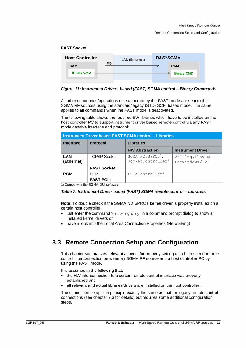
FAST Socket:
Figure 11: Instrument Drivers based (FAST) SGMA control – Binary Commands
All other commands/operations not supported by the FAST mode are sent to the SGMA RF sources using the standard/legacy (STD) SCPI based mode. The same applies to all commands when the FAST mode is deactivated.
The following table shows the required SW libraries which have to be installed on the host controller PC to support instrument driver based remote control via any FAST mode capable interface and protocol:
Instrument Driver based FAST SGMA control – Libraries
Interface Protocol Libraries
HW Abstraction Instrument Driver
LAN (Ethernet)
TCP/IP Socket SGMA NDISPROT1,
SocketController1
VXIPlug&Play or
LabWindows/CVI
FAST Socket
PCIe PCIe PCIeController1
FAST PCIe 1) Comes with the SGMA-GUI software
Table 7: Instrument Driver based (FAST) SGMA remote control – Libraries
Note: To double check if the SGMA NDISPROT kernel driver is properly installed on a certain host controller:
just enter the command ‘driverquery’ in a command prompt dialog to show all
installed kernel drivers or
have a look into the Local Area Connection Properties (Networking)
3.3 Remote Connection Setup and Configuration
This chapter summarizes relevant aspects for properly setting up a high-speed remote control interconnection between an SGMA RF source and a host controller PC by using the FAST mode.
It is assumed in the following that:
the HW interconnection to a certain remote control interface was properly established and
all relevant and actual libraries/drivers are installed on the host controller.
The connection setup is in principle exactly the same as that for legacy remote control connections (see chapter 2.3 for details) but requires some additional configuration steps.
RAMIRQ
RAM
R&S®SGMAHost Controller LAN (Ethernet)
Binary CMD Binary CMD

High-Speed Remote Control
Remote Connection Setup and Configuration
1GP107_0E Rohde & Schwarz High-Speed Remote Control of SGMA RF Sources 22
In the following, a connection setup from a Windows based host controller to a SGT is illustrated: 1. In case of FAST Socket connections it is essential to ensure that the SGMA NDIS
protocol driver service (OS Kernel driver) is properly started manually or by the application software. Keep in mind that both alternatives require administrator rights:
Manually: Open a command prompt dialog as administrator and type:
net start SGMANDISPROT
Application software:
ServiceHandle = OpenSCManager
(NULL, NULL, SC_MANAGER_ALL_ACCESS);
OpenService
(ServiceHandle, “SGMANDISPROT”, SC_MANAGER_ALL_ACCESS);
2. Establish instrument driver session to certain SGT (via LAN Socket or PCIe):
rssgt_init
(ResourceString, idQuery, resetDevice, &SGTHandle);
A handle is returned by this function which has to be used to properly address this certain remote control session.
3. Enable FAST Mode and disable asynchronous command processing (each parameter setting function call returns not until the completion of the SGT hardware settings):
rssgt_UseFastSettings
(SGTHandle, enableFast, disableAsync);
The synchronous mode of operation is comparable with a SCPI command terminated with *OPC? in case of the standard/legacy remote control mode.
4. Disable automatic SGT status queries:
rssgt_SetAttributeViBoolean
(SGTHandle, "", RS_ATTR_QUERY_INSTRUMENT_STATUS, 0);
5. Configure any SGT parameter (e.g. RF frequency):
rssgt_SetAttributeViReal64
(SGTHandle, NULL, RSSGT_ATTR_RF_FREQUENCY, value);
……….. …..
6. Perform parameter queries (e.g. RF frequency):
rssgt_GetAttributeViReal64
(SGTHandle, NULL, RSSGT_ATTR_RF_FREQUENCY, &value);
………. …………
7. Close the established instrument driver session:
rssgt_close
(SGTHandle);
Further source code examples are provided by [13] and [14].

High-Speed Remote Control
Setting Time Performance
1GP107_0E Rohde & Schwarz High-Speed Remote Control of SGMA RF Sources 23
3.4 Setting Time Performance
With the information provided in the previous chapters a (high-speed) remote control connection to a SGMA RF source can be established. The following paragraphs are focusing now on the setting time performance of these interconnections. At first some essential questions regarding the comparability of setting time numbers and the potential impacts on the setting time performance are discussed. Finally a setting time comparison of the legacy remote control approaches with a high-speed interconnection is provided.
3.4.1 Definitions
If it comes to discussions about remote control setting times it is essential to have an exact and clear understanding about:
The different types of setting times (covered time intervals) and
The parameters and factors which may have an impact on the measured/specified setting time
The following figure sheds some light on the setting time types/definitions:
Figure 12: Setting Time Performance – Definitions
3.4.1.1 Setting Time Types
Instrument Setting Time: This time interval includes all instrument internal processing steps which have to be performed to properly adjust a certain parameter based on a received remote control command. It starts directly after the command related interrupt service routine has been left (EOI, End Of Interrupt) and ends after the parameter has been settled within a well-defined tolerance/deviation window (see Figure 13). The instrument setting time which comprises several sub time intervals (e.g. the HW
Kernel driver, Parser,
Database, Org Layer,
Hardware
Function call
Send Cmd IRQ (‚EOI’)
Read
Signal Valid
Send ACK IRQ
Ins
tru
me
nt
Se
ttin
g T
ime
Instrument driver/VISA
Function call returns
Ro
un
d T
rip
Se
ttin
g T
ime
Bu
s
La
ten
cy
R&S®SGMAHost Controller
Kernel driver (opt.)
Kernel driver (opt.)
Instrument driver/VISA

High-Speed Remote Control
Setting Time Performance
1GP107_0E Rohde & Schwarz High-Speed Remote Control of SGMA RF Sources 24
setting time) is normally specified by the instrument data sheets for some selected parameters (e.g. RF frequency/level) only. Hardware Setting Time: The time interval required to adjust a certain instrument parameter by altering the dedicated hardware units (e.g. FPGA registers) is called hardware setting time. This time interval is accessible/measurable by the instrument design engineers only by using an especially instrumented firmware. Round Trip Setting Time: As shown by the figure above, the instrument setting time does neither consider the
Bus latencies nor the
Remote control command processing time consumed by the host controller PC
However if the overall settings time of a certain test application software has to be determined these setting time contributions must be considered, too. In these cases, the so-called round trip setting time finds its application. This time interval accumulates all time contributions starting with the transmission of the settings command (e.g. instrument driver function call) and is ending with the acknowledgment of the controlled instrument received by the host controller (e.g. return of called instrument driver function). In contrast to the instrument or hardware setting time, this time interval can be determined pretty easily by the test application software developer by just using the high precision timer functions provided by the Windows OS.
It has to be kept in mind that a round trip setting time may be significantly influenced by one of the included sub-time intervals:
Physical dimensions of the remote control network (e.g. cable length)
Network traffic/utilization
Performance of the used network components (e.g. 100BaseT instead of 1000BaseT Ethernet hub)
Performance and/or configuration of the used host controller network interface card
Processing performance of the host controller PC
It is therefore crucial to get an impression of all these influencing factors and their respective share in the round trip setting time.
3.4.1.2 Setting Time Impacts
Considered Time Interval: To prevent a comparison of apples with oranges during a discussion about setting times it is essential to have an eye on the setting time type(s) (see 3.4.1.1). Mode of Operation: Sometimes small setting time numbers are only feasible if a certain mode of instrument operation is used (e.g. list mode). Since this constraint may influence the overall configuration flexibility, be aware about these dependencies occurring. Keep in mind that this kind of restrictions does not apply to the R&S FAST mode. Special Options required: Be aware that some other instruments are advertising a kind of high-speed setting but require a dedicated option to allow these competitive setting times. In contrast, the R&S FAST mode comes free of charge with the base instrument not requiring any additional option.
High-Speed Remote Control
Setting Time Performance
1GP107_0E Rohde & Schwarz High-Speed Remote Control of SGMA RF Sources 25
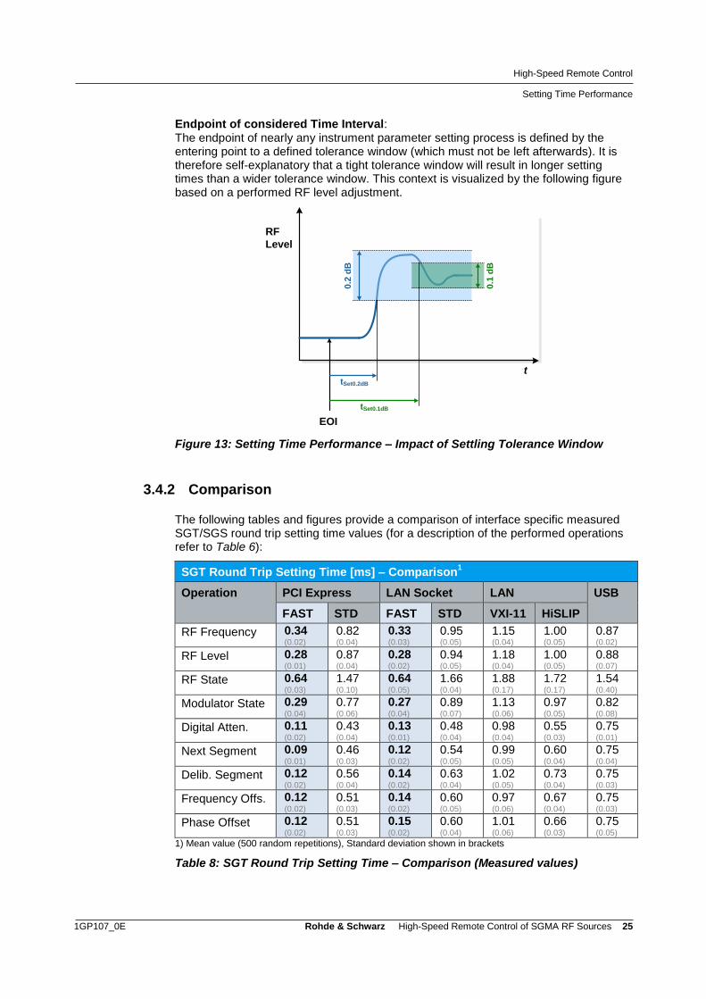
Endpoint of considered Time Interval: The endpoint of nearly any instrument parameter setting process is defined by the entering point to a defined tolerance window (which must not be left afterwards). It is therefore self-explanatory that a tight tolerance window will result in longer setting times than a wider tolerance window. This context is visualized by the following figure based on a performed RF level adjustment.
Figure 13: Setting Time Performance – Impact of Settling Tolerance Window
3.4.2 Comparison
The following tables and figures provide a comparison of interface specific measured SGT/SGS round trip setting time values (for a description of the performed operations refer to Table 6):
SGT Round Trip Setting Time [ms] – Comparison1
Operation PCI Express LAN Socket LAN USB
FAST STD FAST STD VXI-11 HiSLIP
RF Frequency 0.34 (0.02)
0.82 (0.04)
0.33 (0.03)
0.95 (0.05)
1.15 (0.04)
1.00 (0.05)
0.87 (0.02)
RF Level 0.28 (0.01)
0.87 (0.04)
0.28 (0.02)
0.94 (0.05)
1.18 (0.04)
1.00 (0.05)
0.88 (0.07)
RF State 0.64 (0.03)
1.47 (0.10)
0.64 (0.05)
1.66 (0.04)
1.88 (0.17)
1.72 (0.17)
1.54 (0.40)
Modulator State 0.29 (0.04)
0.77 (0.06)
0.27 (0.04)
0.89 (0.07)
1.13 (0.06)
0.97 (0.05)
0.82 (0.08)
Digital Atten. 0.11 (0.02)
0.43 (0.04)
0.13 (0.01)
0.48 (0.04)
0.98 (0.04)
0.55 (0.03)
0.75 (0.01)
Next Segment 0.09 (0.01)
0.46 (0.03)
0.12 (0.02)
0.54 (0.05)
0.99 (0.05)
0.60 (0.04)
0.75 (0.04)
Delib. Segment 0.12 (0.02)
0.56 (0.04)
0.14 (0.02)
0.63 (0.04)
1.02 (0.05)
0.73 (0.04)
0.75 (0.03)
Frequency Offs. 0.12 (0.02)
0.51 (0.03)
0.14 (0.02)
0.60 (0.05)
0.97 (0.06)
0.67 (0.04)
0.75 (0.03)
Phase Offset 0.12 (0.02)
0.51 (0.03)
0.15 (0.02)
0.60 (0.04)
1.01 (0.06)
0.66 (0.03)
0.75 (0.05)
1) Mean value (500 random repetitions), Standard deviation shown in brackets
Table 8: SGT Round Trip Setting Time – Comparison (Measured values)
RF
Level
0.1
dB
0.2
dB
t
EOI
tSet0.1dB
tSet0.2dB

High-Speed Remote Control
Setting Time Performance
1GP107_0E Rohde & Schwarz High-Speed Remote Control of SGMA RF Sources 26
Based on the performed measurements it becomes obvious that FAST Socket connections are as fast as FAST PCIe and up to 8 times faster than legacy connections:
Figure 14: SGT Round Trip Setting Time – Comparison (Measured values)
The following figure visualizes the high setting speed based on a random variation of the digital attenuation. It also indicates the extraordinary fast hardware setting speed performance:
Figure 15: SGT Round Trip Setting Time – Digital Attenuation
500µs
100µs
Round Trip Setting Time
HW Setting Time
High-Speed Remote Control
Setting Time Performance
1GP107_0E Rohde & Schwarz High-Speed Remote Control of SGMA RF Sources 27
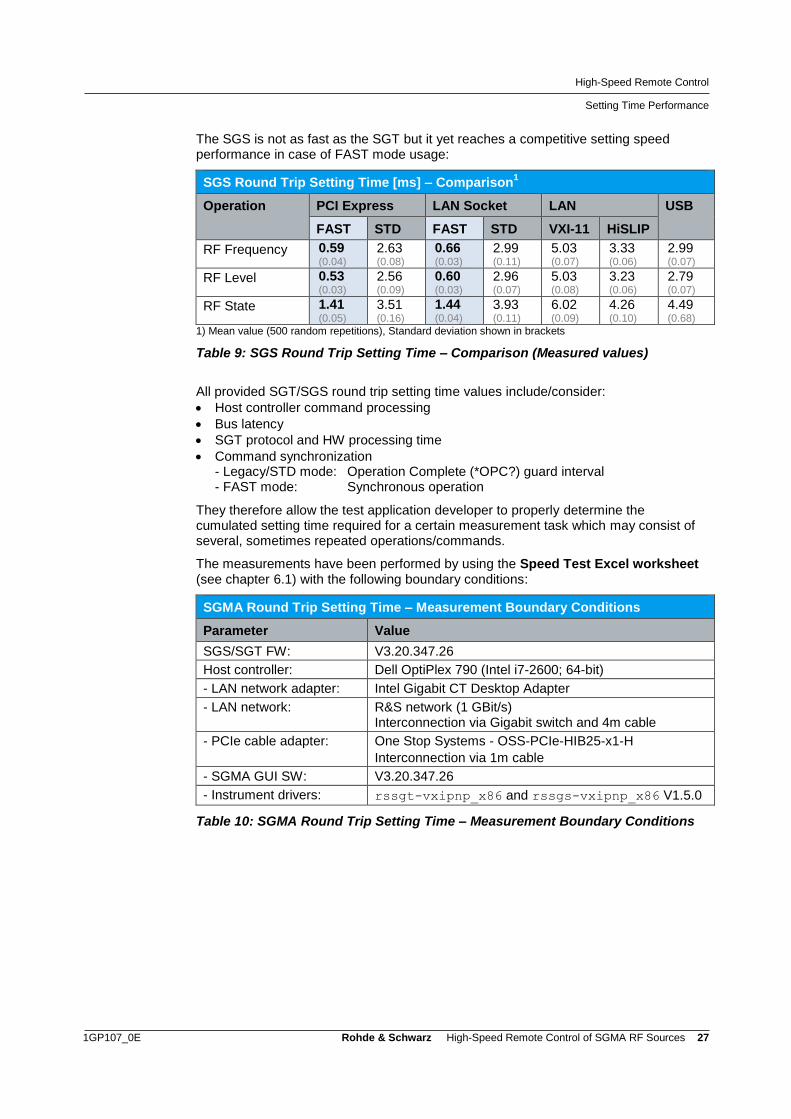
The SGS is not as fast as the SGT but it yet reaches a competitive setting speed performance in case of FAST mode usage:
SGS Round Trip Setting Time [ms] – Comparison1
Operation PCI Express LAN Socket LAN USB
FAST STD FAST STD VXI-11 HiSLIP
RF Frequency 0.59 (0.04)
2.63 (0.08)
0.66 (0.03)
2.99 (0.11)
5.03 (0.07)
3.33 (0.06)
2.99 (0.07)
RF Level 0.53 (0.03)
2.56 (0.09)
0.60 (0.03)
2.96 (0.07)
5.03 (0.08)
3.23 (0.06)
2.79 (0.07)
RF State 1.41 (0.05)
3.51 (0.16)
1.44 (0.04)
3.93 (0.11)
6.02 (0.09)
4.26 (0.10)
4.49 (0.68)
1) Mean value (500 random repetitions), Standard deviation shown in brackets
Table 9: SGS Round Trip Setting Time – Comparison (Measured values)
All provided SGT/SGS round trip setting time values include/consider:
Host controller command processing
Bus latency
SGT protocol and HW processing time
Command synchronization - Legacy/STD mode: Operation Complete (*OPC?) guard interval - FAST mode: Synchronous operation
They therefore allow the test application developer to properly determine the cumulated setting time required for a certain measurement task which may consist of several, sometimes repeated operations/commands.
The measurements have been performed by using the Speed Test Excel worksheet (see chapter 6.1) with the following boundary conditions:
SGMA Round Trip Setting Time – Measurement Boundary Conditions
Parameter Value
SGS/SGT FW: V3.20.347.26
Host controller: Dell OptiPlex 790 (Intel i7-2600; 64-bit)
- LAN network adapter: Intel Gigabit CT Desktop Adapter
- LAN network: R&S network (1 GBit/s) Interconnection via Gigabit switch and 4m cable
- PCIe cable adapter: One Stop Systems - OSS-PCIe-HIB25-x1-H
Interconnection via 1m cable
- SGMA GUI SW: V3.20.347.26
- Instrument drivers: rssgt-vxipnp_x86 and rssgs-vxipnp_x86 V1.5.0
Table 10: SGMA Round Trip Setting Time – Measurement Boundary Conditions

Abbreviations
Setting Time Performance
1GP107_0E Rohde & Schwarz High-Speed Remote Control of SGMA RF Sources 28
4 Abbreviations
ATE Automated Test Equipment
EOI End Of Interrupt
GT/s GigaTransfers per second
HiSLIP High-Speed LAN Instrument Protocol
IDE Integrated Development Environment
IRQ Interrupt ReQuest
IVI Interchangeable Virtual Instrument
LAN Local Area Network
n.a. not applicable
NDIS Network Driver Interface Specification
OPC OPeration Complete
PCI Peripheral Component Interconnect
PCIe Peripheral Component Interconnect Express
PCI-SIG Peripheral Component Interconnect Special Interest Group
SCPI Standard Commands for Programmable Instruments
STD Standard
USB Universal Serial Bus
VISA Virtual Instruments Software Architecture
VME Versa Module Eurocard-bus
VXI VME Extensions for Instrumentation

References
Setting Time Performance
1GP107_0E Rohde & Schwarz High-Speed Remote Control of SGMA RF Sources 29
5 References Manuals:
[1] R&S, SGT100A Operating Manual
[2] R&S, SGS100A Operating Manual
Application Notes:
[3] R&S, 1MA153, Development hints and best practices for using instrument drivers
[4] R&S, 1MA170, Introduction to attribute based instrument drivers
[5] R&S, 1MA171, Control R&S instruments directly from MATLAB
[6] R&S, 1MA196, Interactive remote control or Phython scripts automation
[7] R&S, 1MA228, How to use R&S instruments with LabVIEW
[8] R&S, 1GP79, Top Ten SCPI Programming Tips for Signal Generators
[9] R&S, 1GP72, Connectivity of Rohde & Schwarz Signal Generators
Standards and Specifications:
[10] PCI-SIG, PCI Express Specifications
Miscellaneous:
[11] R&S, SGT Software download area (e.g. SGMA-GUI)
[12] R&S, SGS Software download area (e.g. SGMA-GUI)
[13] R&S, SGT Instrument driver download area (drivers and application examples)
[14] R&S, SGS Instrument driver download area (drivers and application examples)
[15] R&S VISA software library
Appendix
SGMA Speed Test Excel Worksheet
1GP107_0E Rohde & Schwarz High-Speed Remote Control of SGMA RF Sources 30
6 Appendix
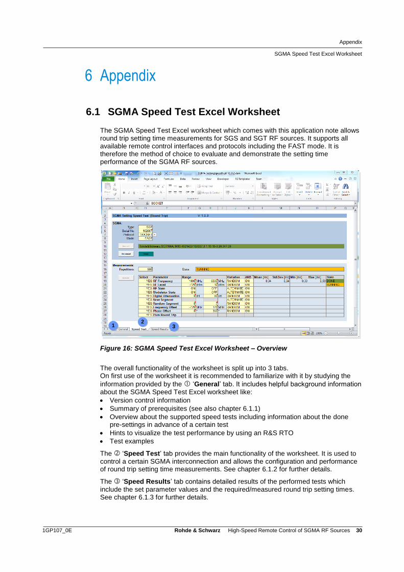
6.1 SGMA Speed Test Excel Worksheet
The SGMA Speed Test Excel worksheet which comes with this application note allows round trip setting time measurements for SGS and SGT RF sources. It supports all available remote control interfaces and protocols including the FAST mode. It is therefore the method of choice to evaluate and demonstrate the setting time performance of the SGMA RF sources.
Figure 16: SGMA Speed Test Excel Worksheet – Overview
The overall functionality of the worksheet is split up into 3 tabs. On first use of the worksheet it is recommended to familiarize with it by studying the
information provided by the ‘General’ tab. It includes helpful background information about the SGMA Speed Test Excel worksheet like:
Version control information
Summary of prerequisites (see also chapter 6.1.1)
Overview about the supported speed tests including information about the done pre-settings in advance of a certain test
Hints to visualize the test performance by using an R&S RTO
Test examples
The ‘Speed Test’ tab provides the main functionality of the worksheet. It is used to control a certain SGMA interconnection and allows the configuration and performance of round trip setting time measurements. See chapter 6.1.2 for further details.
The ‘Speed Results’ tab contains detailed results of the performed tests which include the set parameter values and the required/measured round trip setting times. See chapter 6.1.3 for further details.
32
1

Appendix
SGMA Speed Test Excel Worksheet
1GP107_0E Rohde & Schwarz High-Speed Remote Control of SGMA RF Sources 31
6.1.1 Prerequisites
The following prerequisites have to be fulfilled by the SGMA RF sources and the host controller PC to allow the usage of the Speed Test Excel worksheet to its full extent:
SGMA Speed Test Excel Worksheet – Prerequisites1
Parameter Requirement
SGMA Options SGS: none SGT: K510 (Arbitrary waveform generator)
SGMA FW Release version
SGMA Waveform file SGS: none SGT: ‘PowStepsMSeg.wv’
2
Host Controller SW SGMA-GUI [11], [12] SGT/SGS VXI Plug&Play instrument drivers (32bit, x86) [13], [14]
PCIe A PCIe cable adapter has to be installed on the host controller PC (e.g One Stop Systems OSS-PCIe-HIB25-x1-H) Attention: Take care about required power on/off
sequence (see chapter 2.1.3.4)
FAST Socket The LAN interconnection between the host controller PC and the SGMA must not include routers (TCP/IP routing is not supported)
1) See also ‘General’ tab of the SGMA Speed Test Excel worksheet 2) Comes with the SGMA Speed Test Excel worksheet and has to be saved in the same directory
Table 11: SGMA Speed Test Excel Worksheet – Prerequisites
The SGMA Speed Test Excel worksheet can be opened when all these prerequisites have been considered and a hardware interconnection via any of the available SGMA remote control interfaces has been established.
6.1.2 Speed Test Performance
The ‘Speed Test’ tab of the SGMA Speed Test Excel worksheet allows the:
Configuration and establishment of a remote control interconnection to a certain SGMA RF source
Definition and start of a round trip setting time measurement sequence
Figure 17: SGMA Speed Test Excel Worksheet – SGMA Interconnection
Any round trip setting time measurement has to be started with the configuration of some indispensable parameters which determine the interconnected SGMA RF source
1
2 3
5 4

Appendix
SGMA Speed Test Excel Worksheet
1GP107_0E Rohde & Schwarz High-Speed Remote Control of SGMA RF Sources 32
and the tested interface/protocol. After all of these parameters have been set
thoroughly the interconnection can be established by just pressing the ‘Connect’
key. The status of any connection attempt is instantly shown.
To reset an interconnected SGMA source just press the ‘Preset’ key.
The ‘Disconnect’ key has to be pressed if a certain interconnection has to be released because a new one (e.g. via another protocol or to another SGMA RF source) has to be established.
The desired measurement sequence has to be configured after an interconnection has been established successfully.
It is required to specify the number of repetitions for any remote parameter setting to allow the calculation of several statistical parameters (e.g. arithmetic mean and standard deviation).
Further on, each subtest could be individually parameterized. The subtest may be selected/deselected, the variation range of a certain parameter value can be adapted, the kind of parameter value variation may be changed and for some parameters it is possible to run the test with activated/deactivated ARB (SGT only).
Figure 18: SGMA Speed Test Excel Worksheet – Measurement Configuration
The configured measurement sequence is started by pressing the ‘Measure’ key. A permanently updated measurement status is also displayed. Some statistical parameters (e.g. arithmetic mean) of the subtests performed are shown after a certain measurement sequence has been finished.
Figure 19: SGMA Speed Test Excel Worksheet – Result Statistics
1
2
3
4

Appendix
Code Examples
1GP107_0E Rohde & Schwarz High-Speed Remote Control of SGMA RF Sources 33
6.1.3 Speed Test Detailed Results
In certain cases it may be useful to have a closer look into the performed measurements, the set parameter values and/or the derived round trip setting time values. This kind of detailed results is available via the ‘Speed Result’ tab:
Figure 20: SGMA Speed Test Excel Worksheet – Result Details
6.2 Code Examples
Remote control code examples are provided with the SW archives (Low-level drivers) for SGT [13] and SGT [14].
Ordering Information
Code Examples
1GP107_0E Rohde & Schwarz High-Speed Remote Control of SGMA RF Sources 34
7 Ordering Information Please visit the Rohde & Schwarz product websites at www.rohde-schwarz.com for ordering information on the following Rohde & Schwarz products:
R&S®SGT100A vector signal generator
R&S®SGS100A vector signal generator
Rohde & Schwarz
The Rohde & Schwarz electronics group offers
innovative solutions in the following business fields:
test and measurement, broadcast and media,
secure communications, cybersecurity,
radiomonitoring and radiolocation. Founded more
than 80 years ago, this independent company has
an extensive sales and service network and is
present in more than 70 countries.
The electronics group is among the world market
leaders in its established business fields. The
company is headquartered in Munich, Germany. It
also has regional headquarters in Singapore and
Columbia, Maryland, USA, to manage its operations
in these regions.
Regional contact
Europe, Africa, Middle East +49 89 4129 12345 [email protected] North America 1 888 TEST RSA (1 888 837 87 72)
[email protected] Latin America +1 410 910 79 88
[email protected] Asia Pacific +65 65 13 04 88 [email protected] China +86 800 810 82 28 |+86 400 650 58 96 [email protected]
Sustainable product design
Environmental compatibility and eco-footprint
Energy efficiency and low emissions
Longevity and optimized total cost of ownership
This application note and the supplied programs may only be used subject to the conditions of use set forth in the download area of the Rohde & Schwarz website.
R&S® is a registered trademark of Rohde & Schwarz GmbH &
Co. KG; Trade names are trademarks of the owners.
Rohde & Schwarz GmbH & Co. KG
Mühldorfstraße 15 | D - 81671 München
Phone + 49 89 4129 - 0 | Fax + 49 89 4129 – 13777
www.rohde-schwarz.com