high-resolution terahertz reflective imaging and image restoration
TRANSCRIPT

High-resolution terahertz reflective imagingand image restoration
Sheng-Hui Ding,* Qi Li, Rui Yao, and Qi WangNational Key Laboratory of Tunable Laser Technology, Harbin Institute of Technology,
P.O. Box 3031, No. 2 YiKuang Street, Harbin 150080, China
*Corresponding author: [email protected]
Received 23 July 2010; revised 19 October 2010; accepted 30 October 2010;posted 9 November 2010 (Doc. ID 131636); published 13 December 2010
We present a high-resolution terahertz (THz) reflective imaging system, operating at 2:52 THz, that em-ploys a continuous-wave THz gas laser and a pyroelectric detector. The spatial resolution was evaluatedfrom the system’s modulation transfer function and tested by scanning a series of resolution targets. Tofurther improve the image quality, Lucy–Richardson method was adopted to restore the scanning result.With the scanning spot profile measured using knife edge method, a satisfying restoration result can beobtained. Finally, the system’s performance was observed by imaging some different test objects. © 2010Optical Society of AmericaOCIS codes: 110.6795, 100.3020.
1. Introduction
Terahertz (THz) imaging is a nondestructive andnonionizing imaging technique that shows great ap-plication prospects in biomedicine, security, andquality control [1–4]. With the development of suita-ble sources and detectors, there has been muchresearch interest in THz imaging after its first de-monstration by Hu and Nuss [5–17]. However, dueto the long wavelength of this wave region, the spa-tial resolution of many THz far-field imaging systemsis constrained by the limited spot size, and the ob-tained results are blurred. Most of the reported ima-ging resolution of THz far-field reflective imagingsystems is at the millimeter level. As a result, im-proving the imaging resolution of THz far-field ima-ging systems is always a research focus [9–13]. Salhiet al. transferred the principle of the optical confocalmicroscope to a far-field THz imaging system [9]. Theimage resolution was increased to 0:31 mm at2:52 THz. Zinov’ev et al.also adopted the confocal con-cept and increased the image resolution to 0:25 mm.Their THz source was a semi-insulating GaAs-based
photoconductive antenna excited by a titanium–
sapphire femtosecond laser [10,11]. However, theconfocal setup requires the insertion of two confocalpinholes, which would reduce the illumination power.Therefore, the size of the pinholes is limited and can-not be infinitely small. In Refs. [12,13], the Lucy–Richardson method was introduced to restore theimaging results of THz scanning systems in a trans-mission mode. The systems’ resolutions were around1 mm. However, the restoration effects are not satis-fying due to the limitation of measured point-spreadfunction (PSF). In many practical uses, because THzradiation could not penetrate metals and water, andmost materials show considerable transmission lossfor THz radiation, THz imaging in the transmissionmode is constrained. As a result, reflective THz ima-ging technique is much more attractive, especially inthe biomedicine field [14]. So far, a number of studieshave been carried out to develop a THz reflectiveimaging technique [15–19]. However, those systemsalways requiremore complicateddesigns anddifficultalignment than imaging systems working in thetransmission mode. Moreover, both the image resolu-tion and image quality need further improvement.
In this paper, a high-resolution THz scanning ima-ging system in reflection mode was constructed
0003-6935/10/366834-06$15.00/0© 2010 Optical Society of America
6834 APPLIED OPTICS / Vol. 49, No. 36 / 20 December 2010

based on a commercial continuous-wave (CW) THzgas laser (SIFIR-50 from Coherent Inc.) and a pyro-electric detector (P4-42 from Molectron Inc.). Theprofile of the scanning spot at the imaging planewasmeasured using the knife edge method. The ima-ging resolution capability was studied by scanning aseries of self-made resolution test charts and otherobjects. The Lucy–Richardson method was appliedto restore the blurred imaging results, and satisfyingresults were obtained.
2. Experimental Setup
The imaging system is schematically depicted inFig. 1. The operation frequency of the THz laser is2:52 THz (118:83 μm), and the average output poweris about 50 mW. Five gold-coated off-axis parabolicmirrors are utilized, and the effective focal lengthsare 5.08, 10.16, 10.16, 15.24, 5:08 cm. AnHe–Ne laseris employed to help the alignment. The transmittanceof the silicon wafer for a THz wave is more than 99%.Because the pyroelectric detector must employ achopper for the CW detection, a chopper is insertedat the focus point of P1.M1 andM2 are two planemir-rors. The system design is flexible, so transmissionimaging can be easily accomplished by removingthe two plane mirrors and adjusting the location ofP4 and P5. The path length from the scanning pointto M1 is 7 cm, and the incident angle is 30°. Thesample is placed on a computer-controlled two-dimensional translation stage. The output voltageof the pyroelectric detector is captured to form the im-age. The employment of off-axis parabolicmirrors cangreatly reduce power loss causedby lenses.During ex-periments, the chopping frequency was 10 Hz, andthe acquisition time for each pixelwasabout0:5 s.Be-cause most applications require the ability to imageconcealed targets, in the following experiments, twopieces of paper were used to cover the imaging targetas the barrier (transmittance ∼0:434 ¼ 0:034).
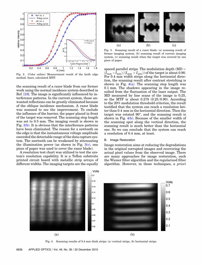
The knife edge method was used to measure thespot profile at the imaging plane. The scanning stepfor the knife bladewas0:05 mminboth thehorizontaland vertical directions. The results can be perfectly fitto a Gaussian distribution (shown in Fig. 2 afternormalization), whose intensity on the detector canbe expressed as a function of the blade position:
IðxÞ ¼ I0
�1þ erf
�2
ffiffiffiffiffiffiffiffiln 2
p x − xcd
��; ð1Þ
where I0 denotes the total spot intensity, x is the posi-tion of the blade, xc is the center of the spot, and d isdefined as the distance between the positions of theblade where 11.9% and 88.1% of the full intensityare transmitted. The horizontal and vertical widthsof the spot are 0.89 and 0:74 mm, respectively. Themodulation transfer function (MTF) and the phasetransfer function (PTF)were estimated from themea-surement result. Because of asymmetry of the systemin thehorizontal direction, the value ofPTF isnot zerofor all spatial frequencies and it would increase a lotat higher spatial frequencies.However, for spatial fre-quencies lower than 1:5 mm−1, the PTF value is smal-ler than 0:1π. The calculated MTF is shown in Fig. 2.Defining the resolution limit at the 20% modulationthreshold indicates spatial resolutions equal to 0.38and 0:33 mm along the horizontal and vertical direc-tions, respectively.
3. Imaging Result and Image Restoration
A. Observation of System Performance
In many previous studies where the illuminationlight is normal to the sample, the imaging resultsare badly influenced by standing waves [18,19]. Thestanding waves are ascribed to unwanted reflectionsfrom optical components in the system. Figure 3(a) is
Fig. 1. (Color online) Experimental setup for THz reflective imaging.
20 December 2010 / Vol. 49, No. 36 / APPLIED OPTICS 6835
the scanning result of a razor blade from our formerwork using the normal incidence system described inRef. [18]. The image is significantly influenced by in-terference patterns. In the current system, those un-wanted reflections can be greatly eliminated becauseof the oblique incidence mechanism. A razor bladewas scanned to see the improvement. To excludethe influence of the barrier, the paper placed in frontof the target was removed. The scanning step lengthwas set to 0:5 mm. The imaging result is shown inFig. 3(b). It is obvious that the interference patternshave been eliminated. The reason for a sawtooth onthe edge is that the instantaneous voltage amplitudeexceeded the detectable range of the data capture sys-tem. The sawtooth can be weakened by attenuatingthe illumination power (as shown in Fig. 3(c), onepiece of paper was used to cover the razor blade).
A resolution test chart was utilized to test the sys-tem’s resolution capability. It is a Teflon substrateprinted circuit board with metallic strip arrays ofdifferent widths. The imaging targets are the equally
spaced parallel strips. The modulation depth (MD ¼ðImax − IminÞ=ðImax þ IminÞ) of the target is about 0.90.For 0:4 mm width strips along the horizontal direc-tion, the scanning result after contrast stretching isshown in Fig. 4(a). The scanning step length was0:1 mm. The shadows appearing in the image re-sulted from the fluctuation of the laser output. TheMD measured by line scans of the image is 0.25,so the MTF is about 0.278 (0:25=0:90). Accordingto the 20% modulation threshold criterion, the resulttestified that the system can reach a resolution bet-ter than 0:4 mm in the horizontal direction. Then thetarget was rotated 90°, and the scanning result isshown in Fig. 4(b). Because of the smaller width ofthe scanning spot along the vertical direction, thescanning result is much better than the horizontalone. So we can conclude that the system can reacha resolution of 0:4 mm, at least.
B. Image Restoration
Image restoration aims at reducing the degradationsin the original corrupted images and recovering theactual pixel values from the observed image. Thereare many approaches for image restoration, suchthe Wiener filter algorithm and the regularized filteralgorithm. However, in those techniques, a priori
Fig. 2. (Color online) Measurement result of the knife edgemethod. Inset, calculated MTF.
Fig. 3. Scanning result of a razor blade: (a) scanning result offormer imaging system, (b) scanning result of current imagingsystem, (c) scanning result when the target was covered by onepiece of paper.
Fig. 4. Scanning results of 0:4 mm thick strips: (a) vertical strips, (b) horizontal strips.
6836 APPLIED OPTICS / Vol. 49, No. 36 / 20 December 2010

knowledge of the noise power plays an important rolein the imagedeblurringprocess.Withoutexactknowl-edge of the noise power, the deblurred results are notsatisfying. Therefore, these methods cannot meet thedemands ofmany practical uses. On the other hand, aprioriknowledge of noise power is not necessarywhenusing the Lucy–Richardson method [20], so here weapplied only the Lucy–Richardson method for imagerestoration. The method is based on the assumptionthat the image was degraded by convolution with aPSF and possibly by additive noise, which can be de-picted as g ¼ f � hþ n, where n is an additive signalindependent noise. The algorithm is based on maxi-mizing the likelihood of the resulting image beingan instance of the original image under Poissonstatistics. The iterative equation can be expressedas following:
f̂ kþ1ðx; yÞ ¼ f̂ kðx; yÞ�hð−x;−yÞ � gðx; yÞ
hðx; yÞ � f̂ kðx; yÞ
�;
ð2Þ
where f̂ is the estimate of the undegraded image, gis the degraded image, and h is the PSF. Once theappropriate PSF is obtained, the image restorationprocess can be effectively performed.
With the spot profile measured using knife edgemethod, the image in Fig. 4(a) was utilized to test
Fig. 5. Image restoration results of 0:4 mm thick strips:(a) vertical strips, (b) horizontal strips.
Fig. 6. Scanning result of a Chinese character “Dragon”: (a) scanning result, (b) image restoration.
Fig. 7. (Color online) Scanning result of a metal sheet: (a) photoof the sample, where the word is “BeLLE”, (b) scanning result, (c)image restoration.
20 December 2010 / Vol. 49, No. 36 / APPLIED OPTICS 6837

the Lucy–Richardson method. The PSF was esti-mated by the following equation:
hðx;yÞ¼�kexp
�−2 ðx−x0Þ
ω2x
Δx2−2 ðy−y0Þ2ω2y
Δy2�; ðx;yÞ∈C
0; others;
ð3Þwhere k is the constant for normalization, ω is theradius of the scanning spot, and Δx, Δy is the scan-ning step length. (x0, y0) is the central point. C is thesupport domain of hðx; yÞ. Twenty iterations wereperformed, and the restoration result is shown inFig. 5(a). Compared with Fig. 4(a), the image con-trast has been greatly improved, and the edges be-come clearer. Moreover, the restored image is muchclosed to the actual size, which indicates that themethod can effectively restore the degraded image.The same process was applied to restore the imagein Fig. 4(b), and the restoration result is shown inFig. 5(b), which could also prove the effectivenessof the restoration method.
The sensitivity of THz radiation to some pigmentsmakes THz imaging a useful tool to reveal concealedpaints or documents [21]. In the experiment, a
Chinese character was written on a white paper witha 2B graphite pencil. The width of the lines is about0:4 mm. The scanning result and the image restora-tion result are shown in Figs. 6(a) and 6(b). The im-age size is 32 × 32, and the step length is 0:2 mm. Byapplying the Lucy–Richardson method, the imageblurring was removed and fine structures could beseen clearly. However, due to the low contrast of thescanning result, there exist some fake shadows in thebackground.
The system was used to scan some characters on ametal sheet [shown in Fig. 7(a)]. The characters areraised and a bit higher than the background, andthe background has a rough surface that exhibitslow reflectance. The scanning step length was setas 0:1 mm. The image size is 32 × 96, so it took about20 min to scan the coin. The scanning result and theimage restoration result after contrast stretching areshown in Figs. 7(b) and 7(c). Fine structures, such asthe horizontal line of “e” and the shape of the back-ground sheet, can all be well restored by applying theLucy–Richardson method. However, the shadows be-tween the characters and the background caused bythe reflection mechanism were a bit exaggerated by
Fig. 8. (Color online) Scanning result of a coin: (a) photo of the sample, (b) scanning result, (c) after fluctuation suppression, (d) imagerestoration.
6838 APPLIED OPTICS / Vol. 49, No. 36 / 20 December 2010

the image restoration process. So the application ofthis image restoration method is constrained whenthe system is used to image samples with large axialstructures. However, this problem may be solvedwhen a normal incidence mechanism was employed.
A metal commemorative coin was also utilized totest the system’s imaging capability. The scanningstep length was set as 0:2 mm to shorten the scan-ning time. The photo of the coin and the scanning re-sult after contrast stretching are shown in Figs. 8(a)and 8(b). The image size is 110 × 142, so it took about2 h to scan the coin. The long scanning time meantthe scanning result was badly influenced by the laseroutput fluctuation. Along the scanning direction, thepower changed gradually and caused striations inthe image. To suppress this phenomenon, an as-sumption was adopted that the detected power is de-termined by f ðx; yÞ ¼ iðx; yÞoðx; yÞ for each pixel,where iðx; yÞ is the illuminating power and oðx; yÞis the reflectance of the object at the point. Thenthe laser fluctuation can be suppressed by removingiðx; yÞ. To estimate the laser output, the object wasfirst segmented from the background, and then iðx; yÞwas estimated by averaging the gray scale at eachline. The suppression result is shown in Fig. 8(c).The result is satisfying, except for the top of the coin.The illuminating power was underestimated, so theobject’s reflectance was overestimated. Then theLucy–Richardson method was utilized to restorethe image, and the result is shown in Fig. 8(d). Com-pared with Fig. 8(b), fine structures, such as theOlympic rings, are enhanced and become more clear.
4. Conclusion
In conclusion, a THz far-field reflective scanningimaging system was constructed. Measurement re-sults of both the knife edge method and the resolu-tion chart certified that the system’s imagingresolution can reach at least 0:4 mm. The scanningresults of different objects validated the strong ima-ging capability of the imaging system. The image re-storation experiments showed that, by employing theLucy–Richardson method, the blurred image result-ing from the limited size of the scanning spot could beeffectively restored with appropriate PSF. The ima-ging result of the penciled character revealed thegreat application potential of the THz imaging tech-nique, such as for art conservation research. To solvethe problem of laser output fluctuation more effec-tively, a beam splitter can be inserted to samplethe laser power and normalize the captured data.However, for objects with axial structures, somefakes and shadows may appear in the restoration re-sult, so further studies should concentrate on thelimitations for the image restoration method andthe effects of diffraction on the restoration result.The future application of the image restorationtechnique can be complementary to hardware im-provement for image resolution improvement.
References
1. R. M. Woodward, “Terahertz technology in global homelandsecurity,” Proc. SPIE 5781, 22–31 (2005).
2. E. Pickwell and V. P. Wallace, “Biomedical applications ofterahertz technology,” J. Phys. D 39, R301–R310 (2006).
3. H. B. Wallace, “Analysis of RF imaging applications atfrequencies over 100 GHz,” Appl. Opt. 49, E38–E47 (2010).
4. C. Jansen, S. Wietzke, O. Peters, M. Scheller, N. Vieweg, M.Salhi, N. Krumbholz, C. Jördens, T. Hochrein, and M. Koch,“Terahertz imaging: applications and perspectives,” Appl.Opt. 49, E48–E57 (2010).
5. B. B. Hu andM. C. Nuss, “Imaging with terahertz waves,”Opt.Lett. 20, 1716–1718 (1995).
6. T. Löffler, T. May, C. am Weg, A. Alcin, B. Hils, and H. G.Roskos, “Continuous-wave terahertz imaging with a hybridsystem,” Appl. Phys. Lett. 90, 091111 (2007).
7. Z. D. Taylor, R. S. Singh, E. R. Brown, J. E. Bjarnason, M. P.Hanson, and A. C. Gossard, “A reflection based, pulsed THzimaging system with 1 mm spatial resolution,” in MicrowaveSymposium, 2007. IEEE/MTT-S International (IEEE, 2007),pp. 1161–1164.
8. H. Richter, M. Greiner-Bär, S. G. Pavlov, A. D. Semenov, M.Wienold, L. Schrottke, M. Giehler, R. Hey, H. T. Grahn, andH.-W. Hübers, “A compact, continuous-wave terahertz sourcebased on a quantum-cascade laser and a miniature cryocoo-ler,” Opt. Express 18, 10177–10187 (2010).
9. M. A. Salhi, I. Pupeza, and M. Koch, “Confocal THz laser mi-croscope,” J. InfraredMilli. Terahz. Waves 31, 358–366 (2010).
10. N.N.Zinov’ev,A.V.Andrianov,A.J.Gallant, J.M.Chamberlain,and V. N. Trukhin, “Contrast and resolution enhancement in aconfocal terahertz video system,” JETP Lett. 88, 492–495(2009).
11. N. N. Zinov’ev and A. V. Andrianov, “Confocal terahertzimaging,” Appl. Phys. Lett. 95, 011114 (2009).
12. Y. Li, L. Li, A. Hellicar, and Y. J. Guo, “Super-resolution recon-struction of terahertz images,” Proc. SPIE 6949, 69490J(2008).
13. Q. Li, Q. Yin, R. Yao, S. Ding, and Q. Wang, “Continuous-waveterahertz scanning image resolution analysis and restora-tion,” Opt. Eng. 49, 037007 (2010).
14. Z.D.Taylor,R.S.Singh,M.O.Culjat,J.Y.Suen,W.S.Grundfest,H. Lee, and E. R. Brown, “Reflective terahertz imaging ofporcine skin burns,” Opt. Lett. 33, 1258–1260 (2008).
15. P. Dean, S. Khanna, S. Chakraborty, M. Lachab, A. G. Davies,and E. H. Linfield, “Diffuse reflection imaging at terahertzfrequencies for security applications,” Proc. SPIE 6741,67410R (2007).
16. V. P. Wallace, E. MacPherson, J. A. Zeitler, and C. Reid,“Three-dimensional imaging of optically opaque materialsusing nonionizing terahertz radiation,” J. Opt. Soc. Am. A25, 3120–3133 (2008).
17. S. Huang, P. C. Ashworth, K. W. C. Kan, Y. Chen, V. P. Wallace,Y.-T. Zhang, and E. Pickwell-MacPherson, “Improved samplecharacterization in terahertz reflection imaging and spectro-scopy,” Opt. Express 17, 3848–3854 (2009).
18. Q. Li, R. Yao, Q. Yin, J. Shan, and Q. Wang, “2:52 THz scan-ning reflection imaging and image preprocessing,” Proc. SPIE7277, 72770J (2009).
19. Q. Song, F. Yu, Y. Zhao, C. Zhang, Q. Yu, M. Liu, and X. Liu,“The restoration of CW THz images based on phase analysis,”Proc. SPIE 7443, 74432G (2009).
20. D. S. C. Biggs and M. Andrews, “Acceleration of iterative im-age restoration algorithms,” Appl. Opt. 36, 1766–1775 (1997).
21. E.Abraham,A.Younus,A.ElFatimy,J.CDelagnes,E.Nguéma,and P. Mounaix, “Broadband terahertz imaging of documentswritten with lead pencils,” Opt. Commun. 282, 3104–3107(2009).
20 December 2010 / Vol. 49, No. 36 / APPLIED OPTICS 6839