high resolution imaging of the cosmic microwave background...
TRANSCRIPT

High Resolution Imaging of theCosmic Microwave Background and
the angular power spectrumRafael Rebolo
Instituto de Astrofísica de CanariasConsejo Superior de Investigaciones Científicas
and
VSA ConsortiumCavendish Lab. Cambridge
Jodrell Bank Obs.IACGranada, 17 de Septiembre de 2004 JENAM

Outline
• CMB anisotropies: introduction• VSA• CMB mapping. Peaks in the angular power
spectrum: cosmological implications• Methodology and Constraints on
cosmological parameters
• Conclusions

WMAPCMB powerspectrum
High l multipolesbring information on :•Initial spectrum offluctuations•Inflationary scenarios• Neutrino contribution to thematter content of the Universe•....

Very Small Array (VSA)
• Array of 14 conical hornantennas located at Tenerife
• HEMT based receiversworking in the range 26 - 36 GHz
• Single-channel analoguephase-switched correlator1.5 GHz bandwidth.
• Horn reflectors mounted ona tip table. Close packing
• Compact configurationFoV 4.5 degrees. Resolutionelement : 15 arcmin.

The VSA consortiumCambridge Astrophysics Group
Jodrell Bank Observatory
Instituto de Astrofísica de Canarias
Richard Davis Rod Davies Clive DickinsonBob Watson Kieran Cleary Richard BattyeColin Baines Jason Marshall Eddie BlackhurstAlthea Wilkinson J. P. Leahy Yasser Hafez
Mike Hobson (PI) Keith Grainge( PM) Paul Scott Anthony LasenbyMike Jones Richard Saunders Angela Taylor Rüdiger KneisslKlaus Maisinger Anze Slosar Richard Savage Katy LancasterNutan Rajguru Anna Scaife Dave Titterington Guy PooleyRoger Boysen Mike Crofts Liz Waldram Roger DaceTony Brown Jerry Czeres Ian Northrop Clive Shaw
Rafa Rebolo Jose Alberto Rubiño
Carlos Gutierrez
Ricardo Genova
Jose Luis Salazar Carmen Padilla

The Very Small ArrayExtended configuration
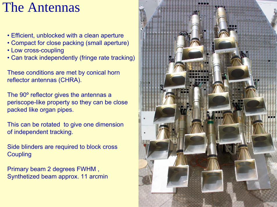
The Antennas
• Efficient, unblocked with a clean aperture• Compact for close packing (small aperture)• Low cross-coupling • Can track independently (fringe rate tracking)
These conditions are met by conical horn reflector antennas (CHRA).
The 90º reflector gives the antennas a periscope-like property so they can be closepacked like organ pipes.
This can be rotated to give one dimension of independent tracking.
Side blinders are required to block cross Coupling
Primary beam 2 degrees FWHM ,Synthetized beam approx. 11 arcmin
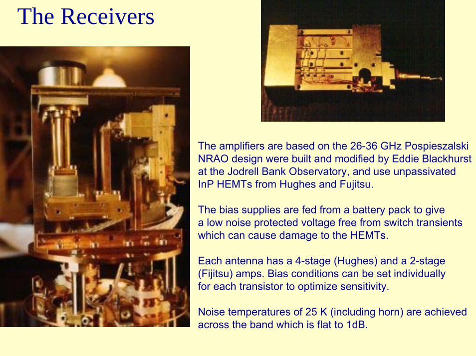
The Receivers
The amplifiers are based on the 26-36 GHz PospieszalskiNRAO design were built and modified by Eddie Blackhurstat the Jodrell Bank Observatory, and use unpassivatedInP HEMTs from Hughes and Fujitsu.
The bias supplies are fed from a battery pack to give a low noise protected voltage free from switch transientswhich can cause damage to the HEMTs.
Each antenna has a 4-stage (Hughes) and a 2-stage (Fijitsu) amps. Bias conditions can be set individually for each transistor to optimize sensitivity.
Noise temperatures of 25 K (including horn) are achieved across the band which is flat to 1dB.


VSA Extended
Configuration
VSA Extended
Configuration

Window function

Selection of Fields The 7 VSA Regions
VSA1: 7 fieldsα 00h19m22s δ +29º16’39”
VSA2: 7 fields09 40 53 +31 46 21
VSA3: 7 fields15 35 13 +42 45 05
VSA5: 3 fields03 05 45 +27 16 35
VSA6: 3 fields07 24 48 +55 05 00
VSA7: 3 fields12 28 14 +53 48 25
VSA8: 7 fields17 34 58 +40 53 07
100 µm
Fields chosen to limit Galactic and extragalactic emission by avoiding:
• Bright radio sources (>500 mJy) via NVSS and GB6• Bright galaxy clusters via Ebeling et al. and Abell catalogues• Diffuse galactic emission: Synchrotron (408 MHz Halslam et al 1981),
Free-free (Hα WHAM Haffner et al 2003),Dust (100 µm Schlegel et al 1998)

Dickinson et al. 2004 (MNRAS in press)
Typical rms values of 5-25 microK beam-1

Comparison with WMAP
WMAP noise is 100 – 200 µK per 12.6’ pixel as compared to ~20 µK per 11’ beam in the mosaic

Before aftersubtraction of radiosources
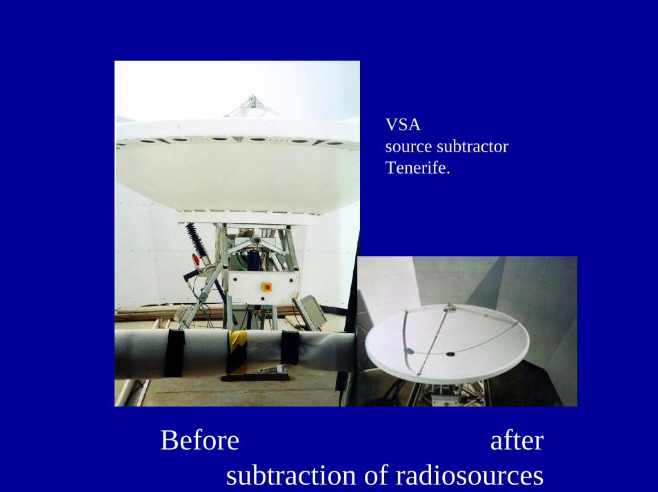
VSA source subtractorTenerife.
Before aftersubtraction of radiosources

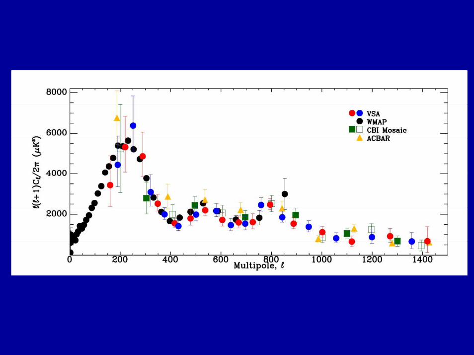
VSA CMB angular power spectrum(compact + extended configuration)
(two alternate binnings)

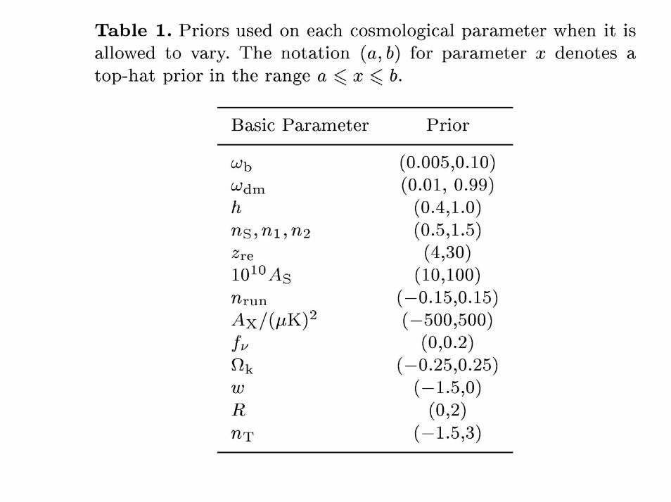
Methodology
Adiabatic models
Initial fluctuation spectrum

Running index

For slow-roll inflation to be well defined:
See e.g. (Leach & Liddle 2003)
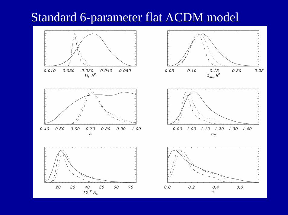
Standard 6-parameter flat ΛCDM model
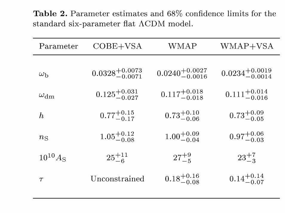

FlatΛCDMmodel
+Runningindex

Constraintson Runningindex

Omega matter
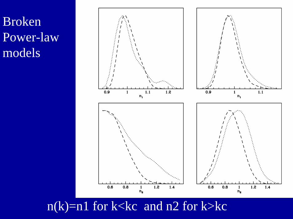
BrokenPower-lawmodels
n(k)=n1 for k<kc and n2 for k>kc
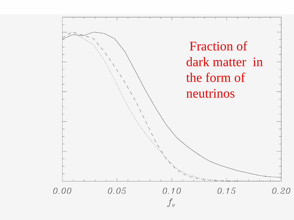
Fraction ofdark matter in the form ofneutrinos

External priors:
• 2dF (Percival et al. 2001, 2002)
• 2df + fgas (gas fraction in dynamically relaxedclusters of galaxies Allen et al. 2002)
• 2df+fgas+XLF (observed local X-ray luminosityfunction of clusters of galaxies, Allen et al. 2003)
• 2dF+HST (Key project Freedman et al. 2001)
• 2dF+ Cosmic Shear (Hoekstra et al. 2002)

Flat Lambda CDM models

Marginalizeddistribution forcosmological parametersNon-flat Lambda CDM
All CMB WMAP+VSA -----WMAP .........
External priors: 2dF + SNIa

Continuation...

General Lambda CDM analysis
Cosmologicalparameters (68 %C.L.) .For neutrinos and R (95% C.L.)
Rebolo et al. 2004(MNRAS in press)

General Lambda CDM analysis

Conclusions• In flat Lambda CDM models, VSA modifies thelimits on the cosmological parameters as comparedwith those derived by WMAP, while still remainingcompatible.
•The evidence for a negative value of the runningindex found with these models is much weakerwhen the most general analysis (non-flat, 12 parameters) is performed.
• Upper limit on Neutrino fraction < 0.087 (95%C.L.) mν < 0.32 eV
(if the three neutrino types have equal mass)

Fig. 9

The future - Enhanced VSA3x19-field mosaics (shallow)
1x3-field mosaic (deep)
The next step is to increase the ℓ-range further up to 2500 by using bigger carbon fibre reflectors(55 cm diameter) and scattering the antennas to the edges of the table.
With a shallow survey with big mosaics the 4 and 5 the peaks can be investigated.
A limited deep survey can probe for the CBI excess of sources at ℓ>2000.