high pressure system- anaesthesia machine
TRANSCRIPT

SRI SIDDHARTHA MEDICAL COLLEGE
High Pressure System
Chairperson : Dr.S.B.Gangadhar
Moderator : Dr. C.N. Ramesh
Presenter : Dr. Daber Pareed

Introduction
• Anaesthesia work station is a device which delivers a precisely known but variable gas mixture, including anaesthetizing and life sustaining gases.

History• The original concept of Boyles machine was invented by the british
anaesthetist H.E.G Boyle in 1917
• 1920 – A vaporizing bottle is incorporated with the machine.
• 1926- A 2nd vaporizing bottle and by pass controls are incorporated.
• 1930- A plunger device is added to the vaporizing bottle.
• 1933 – A dry bobbin type of flowmeter is introduced.
• 1937 – Rotameters displayed dry bobbin typle of flowmeters

Anaesthesia Work Station
• Integrates most of the components necessary for administration of anesthesia into single unit.
• Standard guidelines have been given to manufacturers for minimum
performance, design, characteristics and safety requirements of machine.

During the past two decades, the progression of anaesthesia machine standards has been as follows-
• 1979 – American National standards Institute.
• 1988 – American society for Testing and Materials,
• 1994 – ASTM F1161-94 ( reapproved in 1994 and discontinued in 2000)
• 2005 – International Eletrical commission.
• 2005 – ASTM (reapproved) F1850
• European Standard is EN740
https://www.astm.org/Standards/F1850.htm

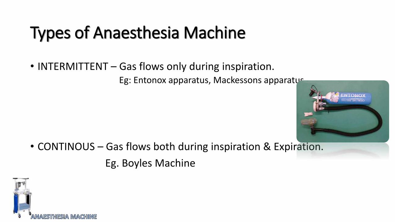
Types of Anaesthesia Machine
• INTERMITTENT – Gas flows only during inspiration.Eg: Entonox apparatus, Mackessons apparatus
• CONTINOUS – Gas flows both during inspiration & Expiration.
Eg. Boyles Machine
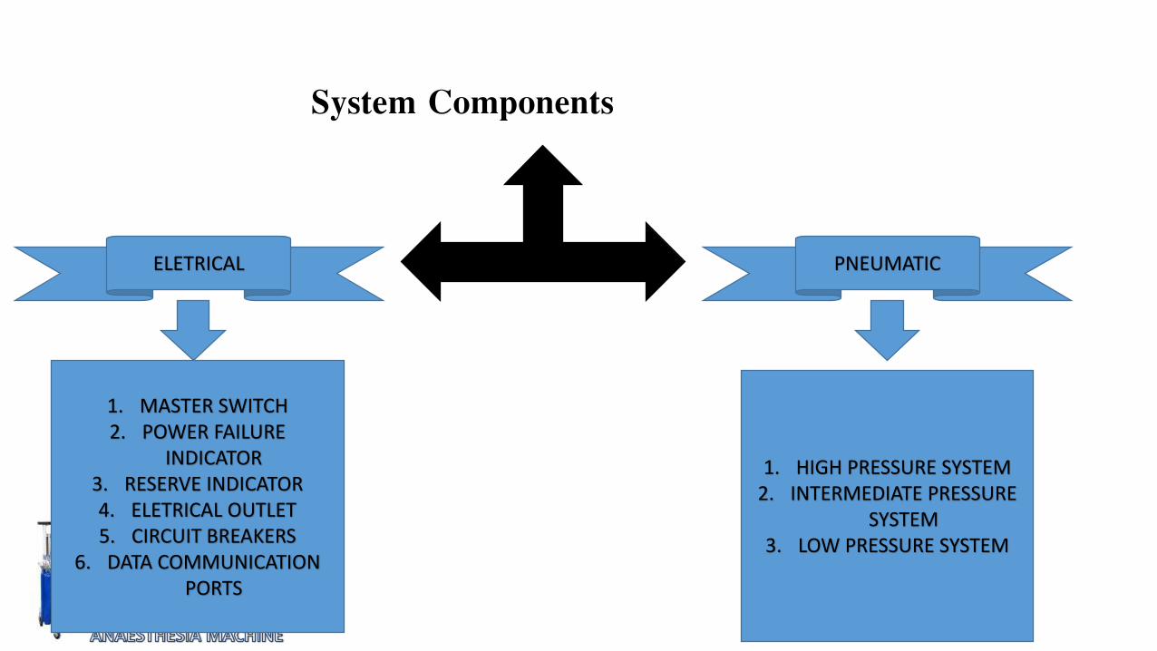
System Components
ELETRICAL PNEUMATIC
1. MASTER SWITCH2. POWER FAILURE
INDICATOR3. RESERVE INDICATOR4. ELETRICAL OUTLET5. CIRCUIT BREAKERS
6. DATA COMMUNICATION PORTS
1. HIGH PRESSURE SYSTEM2. INTERMEDIATE PRESSURE
SYSTEM3. LOW PRESSURE SYSTEM


Components of Pressure System


Medical Gas Cylinders – Components
Body
• Previously most of the gas cylinders are constructed of steel, with various alloys added.
• In recent years, it have moved away from traditional steel cylinders towards steel carbon fiber cylinders. These can hold more gas than the older steel counterparts
• These are especially useful in MRI environment.
• Cylinders have a marking “3AA” are manufactured using steel and “3ALM” or “3AL” indicated that cylinder is made from aluminium.

Valve
• Cylinders are filled and discharged through a valve attached to the neck.
• Made up of Bronze or Brass.
PORT- it is the point where the gas exits.
STEM- each valve contains a stem or shaft, that is rotated during valve opening or closing.

VALVE
PACKED VALVE –
• most cylinder valves are of the packed type.
• The Stem is sealed by resilient packing such as Teflon, which prevents leaks around the threads.
DIAPHRAGM VALVE –
• In a diaphragm valve closure between the cylinder interior and the atmosphere is accomplished by using a seal, usually metal to metal, and a bonnet nut that clamps one or more circular discs in place.
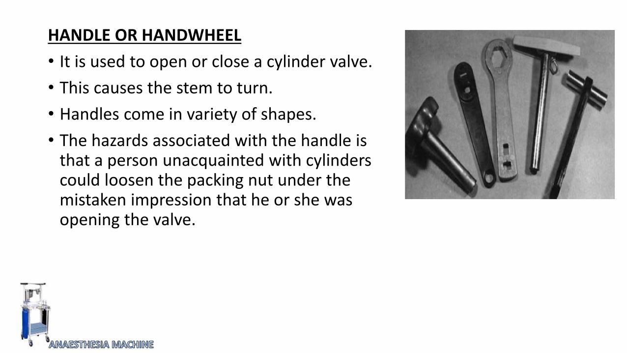
HANDLE OR HANDWHEEL
• It is used to open or close a cylinder valve.
• This causes the stem to turn.
• Handles come in variety of shapes.
• The hazards associated with the handle is that a person unacquainted with cylinders could loosen the packing nut under the mistaken impression that he or she was opening the valve.

PRESSURE RELIEF DEVICES
• Every cylinder is fitted with a pressure relief (safety relief, safety) device whose purpose is to vent the cylinder’s contents to atmosphere, if the pressure of the enclosed gas increases to a dangerous level.
RUPTURE DISC:
• The rupture disc is non-reclosing device with a disc held against an orifice.
• When the predetermined pressure is reached, the disc ruptures and allows the cylinder contents to be discharged.
• It protects against excess pressure as a result of high temperature or overfilling.

FUSIBLE PLUG
• The fusible plug is thermally operated, non-reclosing pressure-relief device with plug held against the discharge channel.
• It offers protection from excessive pressure caused by a high temperature but not from overfilling.
• The yield temp; is the temp; at which the
fusible material becomes sufficiently soft to extrude
from its holder.
So, that cylinder contents gets discharged.
COMBINATION RUPTURE DISC/FUSIBLE PLUG
• It can be used to prevent bursting at a predetermined pressure unless the temperature is high enough to cause the fusible material to yield.
Pressure Relief Device

PRESSURE RELIEF VALVE
• It is a spring-loaded device designed to reclose and prevent cylinder contents from being discharged after a normal pressure has been restored.
CONICAL DEPRESSION
• It is present on the small cylinders above the safety relief device, and it receives the retaining screw of the yoke.

SIZES OF GAS CYLINDERS
• Classified by using a letter code, with A being the smallest.
• Size E is the cylinder most commonly used on anesthesia machine and for patient transport and resuscitation.
• Size D cylinders are used for limited supplies of gases where size and weight considerations are important.


CONTENTS AND PRESSURE
• In a cylinder containing non-liquefied gas, the pressure declines steadily as the contents are withdrawn. Therefore, the pressure can be used to measure the cylinder contents.
• In a cylinder containing a liquefied gas, the pressure depends on the vapour pressure of the liquid and is not an indication of the amount of gas remaining in the cylinder as long as the contents are partly in the liquid phase.
• Weight can be used to determine the amount of liquid in these cylinders.
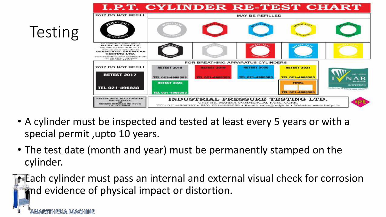
Testing
• A cylinder must be inspected and tested at least every 5 years or with a special permit ,upto 10 years.
• The test date (month and year) must be permanently stamped on the cylinder.
• Each cylinder must pass an internal and external visual check for corrosion and evidence of physical impact or distortion.

Filling
• The pressure in a filled cylinder at 70 degree F may not exceed the service pressure marked on the cylinder except for some nonliquified, non inflammable gases.
• For the gases other than nitrous oxide and carbon dioxide, the pressure in the cylinder is 130degree F, may not exceed 1.25 times the maximum permitted filling pressure at 70degree F
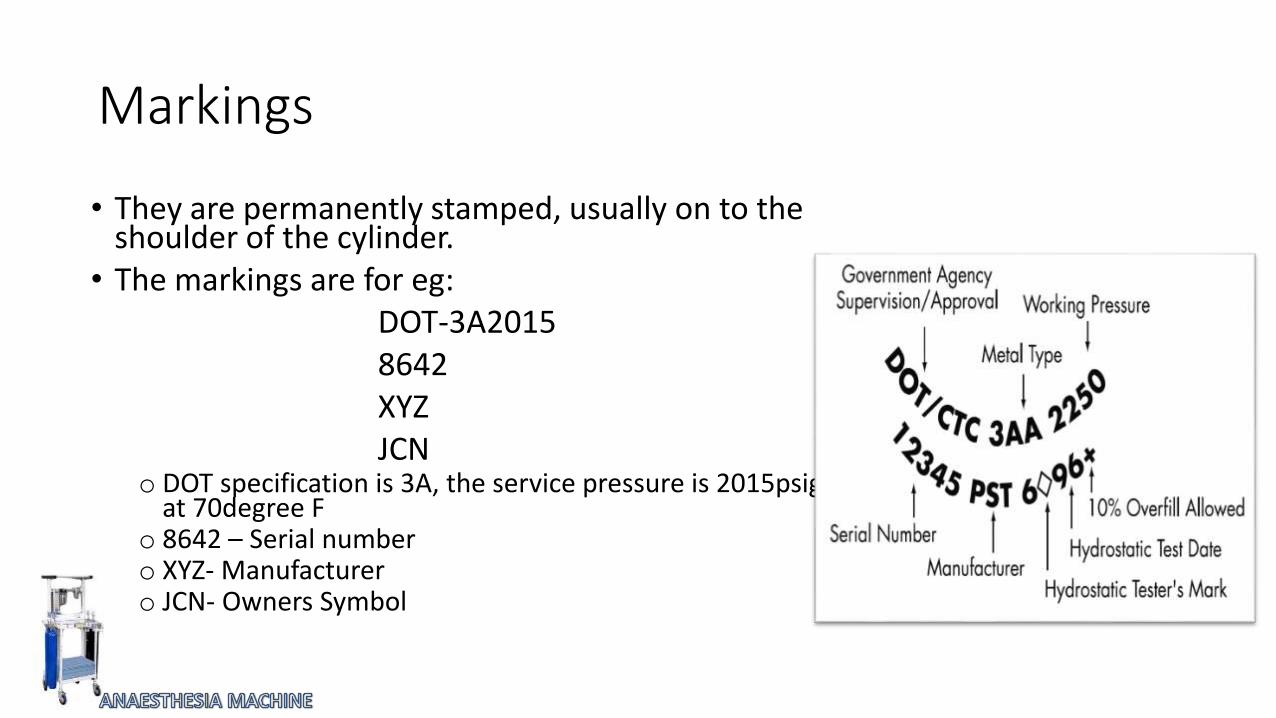
Markings
• They are permanently stamped, usually on to the shoulder of the cylinder.
• The markings are for eg:DOT-3A20158642XYZJCN
o DOT specification is 3A, the service pressure is 2015psig at 70degree F
o 8642 – Serial numbero XYZ- Manufacturero JCN- Owners Symbol
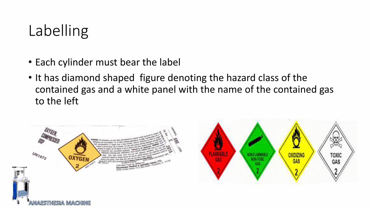
Labelling
• Each cylinder must bear the label
• It has diamond shaped figure denoting the hazard class of the contained gas and a white panel with the name of the contained gas to the left

Tags
• A typical tag has 3 sections labelled- FULL, IN USE & EMPTY
• When a cylinder is put into service, the FULL portion of the tag should be detached.
• When the cylinder is empty, the IN USE portion should be removed, leaving the EMPTY label.

Summary of Gas Cylinders

Components of High pressure System- Hanger Yoke
The Hanger yoke orients and supports the cylinder, provides a gas tight seal and ensures a
unidirectional gas flow.
The workstation standard requires that there be at least one yoke for oxygen and nitrous oxide.
Parts:
1. Body: Principle framework of yoke.
• Threaded into frame of machine, supports cylinder.
• It Provides support to the cylinder
• On the swinging gate, type of yoke, distal part is hinged.
• Hinged part can be swung side

2. Retaning Screw• The retaining screw is threaded into the distal end of the yoke.
• Tightening the screw passes the cylinder valve outlet against the washer and nipple so that the gas-tight seal is achieved.
3. Nipple-• The nipple is part of the yoke through which gas enters the
machine.
• It projects from the yoke and fits into the port on the cylinder valve.
• If the nipple is damaged, it may be impossible to obtain a tight seal with the cylinder valve.

4. Index Pins• The pin index system are below the nipple.
• The holes into which the pins are fitted must be of a specific depth.
5. Washer• A washer is placed around the nipple to produce a seal between the
cylinder valve and the yoke.
• A washer is usually supplied with each full cylinder
• Bodok seal is made of non combustible material, has a metal periphery to make it long lasting
• Should be <2.4mm thick
• Only one seal allowed between the valve and yoke.

6. Filter- (100 µm maximum)• The anaesthesia work station standard requires that a filter be
installed between the cylinder and pressure regulator to prevent particulate matter from entering the machine.
7. Check Valve Assembly-• It allows gas from cylinder to enter machine but prevents gas
from exiting machine when yoke has no cylinder. Allows replacement of cylinders without losing gas
Prevents transfer of gas from a cylinder with high pressure to one with low pressure if connected to double yoke and turned on simultaneously.
A yoke should not never be left vacant.
After tightening a cylinder to yoke should look for leaks
After cylinder is attached valve should be closed.

• A typical check valve consist of plunger that slides away from the side where the pressure is greater.
• When the cylinder pressure exceeds the pressure on the machine side, the plunger is pushed to the right and gas passes around it and into the machine.
• When the machine pressure exceeds the cylinder pressure, the plunger moves to the left, blocking the gas flow.

Safety device in yoke
• Woods alloy- fusible plug of bismuth, lead, cadmium melts at 150-170 degree F, prevents explosion
• Copper frangible disc- ruptures at very high pressure.

Limitations of Check Valve assembly
• The check valves are not designed to act as permanent seals for empty yokes.
• Small amounts of gases can escape if the yoke is empty or an empty cylinder (or cylinder with low pressure) and valve open is present in the yoke.

In order to minimize such losses –
• Yokes should not be left vacant for extended periods.
• An empty cylinder should be replaced as soon as possible , if not then,
• An yoke plug can be used to prevent gas leak
Or
• An empty cylinder can be left behind after closing the valve.

• It is important that cylinder valves and yokes not be contaminated with oil or grease, because this could present a fire hazard.
• Before a cylinder is mounted in place, the yoke should be checked to make certain that the two Pin Index safety pins are present.
• A missing pin could allow the safety system to be bypassed.
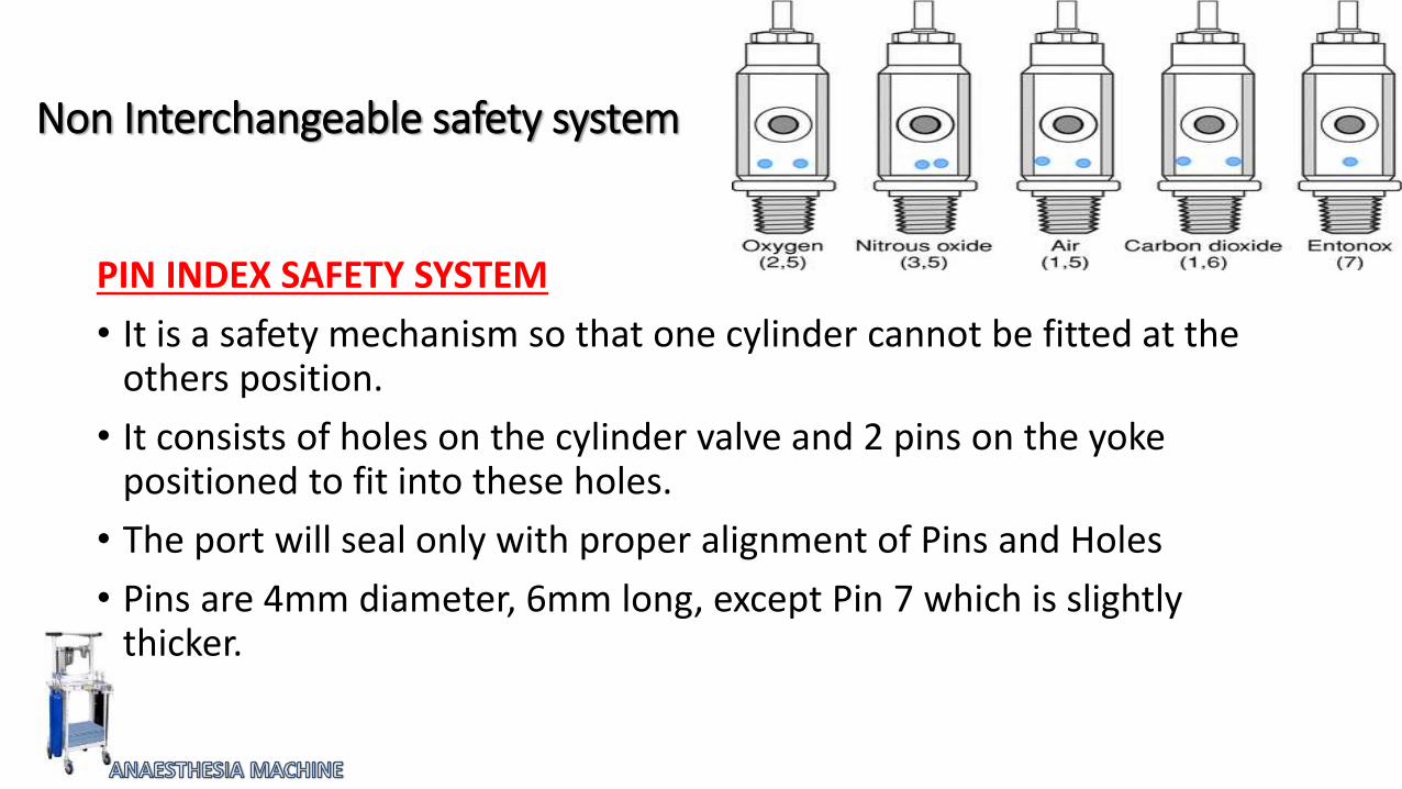
Non Interchangeable safety system
PIN INDEX SAFETY SYSTEM
• It is a safety mechanism so that one cylinder cannot be fitted at the others position.
• It consists of holes on the cylinder valve and 2 pins on the yoke positioned to fit into these holes.
• The port will seal only with proper alignment of Pins and Holes
• Pins are 4mm diameter, 6mm long, except Pin 7 which is slightly thicker.


Limitations of Pin Index system
• A wrong cylinder can be placed in the yoke, if
2 washers are placed.
Pins on the yoke are broken
Holes in the cylinder valve are two deep


Cylinder Pressure Indicator (Bourdon Pressure Gauge)

Bourdon Pressure Gauge
• It displays the cylinder pressure for each gas supplied by cylinders.
• The indicator may be located near the cylinders or on a panel on the front of the machine.
• Hollow metal tube of copper alloy, bent into a curve, sealed and linked to a clock – like mechanism.
• Other end is connected to the gas source.

• Increase in gas pressure inside the tube causes it to straighten.
• As the pressure falls, the tube resumes its curved shape.
• These motions are transmitted to an indicator which moves on a calibrated scale through clock like mechanism.
• Gauages are required to be calibrated in kilopascals (kPa)

Safety features in cylinder Pressure Indicator
• Gauge is usually color coded.
• Name and symbol of gas are written over dial.
• If bourdon tube ruptures gas is vented from back side.
• Gauges are angled and placed in such a way that it can be easily read by anaesthetist.
• Instructions like “use no oil’’ “open the valve slowly’’ are written on the gauge.

Electronic Cylinder Pressure Indicator
• Light emitting diodes(LED’S)in electronic pressure gauge indicate-
Cylinder Valve is close – Dark Color
Cylinder Valve is Open-
Pressure adequate – Green
Pressure inadequate – Red

Pressure Regulators
• The pressure in cylinder varies. To maintain constant flow with changing supply pressure, the anaesthesia machine is fitted with pressure regulators
• A pressure regulator reduces the high and variable pressure found in a cylinder to a lower, more constant pressure suitable for use in anaesthesia machine (40-45 Psig)

Physical Principle
A large pressure acting over a small area is balanced by a small pressure over a larger area
SAFETY FEATURES!!
• Pressure regulators have safety relief valves
• If due to any reason there is build up of pressure in pressure regulator then the safety valve blow off at a set pressure of 525 k pa(70psi)