high power nuclear electric propulsion
TRANSCRIPT
The 32nd International Electric Propulsion Conference, Wiesbaden, Germany
September 11 – 15, 2011
1
HIGH POWER NUCLEAR ELECTRIC PROPULSION
IEPC-2011-061 Presented at the 32nd International Electric Propulsion Conference,
Wiesbaden • Germany
September 11 – 15, 2011
Richard Blott
Director, Space Enterprise Partnerships Ltd, Eastergate, West Sussex, PO20 3SJ, UK.
Anthony Donaldson
Specialist System Concepts, Rolls Royce plc, Derby, DE21 7XX, UK.
and
Professor Marino Mazzini Director, Acta Srl, Pisa, 56100, Italy
Abstract: The EC FP7 High Power Electric Propulsion: a Roadmap for the Future (HiPER)1 investigated
nuclear fission electrical power generation for the exploration of the outer solar system. Compatibility with the
Ariane 5ECA lift and fairing dimensions was a constraint. From previous studies a specific mass of 25kg/kWe
was thought the best that could be achieved with current and emerging technology. In principle this constrained
the power generating capability to 200 kWe which became the target for a concept design. The three main
pillars of the investigation were the core reactor, the shield and the power conversion system. However the
potential to achieve the individual capabilities had also to be consistent with a viable, overall system architecture
as well as each other. Initial investigation demonstrated the specific mass benefit of Brayton cycle power
conversion compared to thermo-electric or thermionic. But it was not clear whether a direct cycle, gas cooled, or
indirect cycle, liquid metal cooled reactor, was the best way forward. Modelling and simulation demonstrated
the importance of operating temperature and shield design. Radiator size decreases to the power three with
increasing operating temperature. Conversely the creep life of the most advance refractory metal alloys limited
the temperature at the hottest part of the turbo-alternator, the turbine inlet, to about 1100ºK. A shaped shield
to match the reactor neutron and gamma fluxes gave significant specific mass benefits. Concept designs2 for
both direct and indirect Brayton cycle power conversion were developed taking account of the technical
challenges which would have to be overcome. A road map3 to realize the concept design focused on technical
developments to achieve high turbine inlet temperature with materials with adequate creep life and low mass
radiator design with manageable areas. It also included recommendations for shield penetration, reactor
control, propellant storage, power management and distribution mass technologies and optimised system
architectures.
1 HiPER DOW 218859 i2r2 dated May 2008.
2 HiPER Nuclear Power Generation Concept Design HiP-SEP-D-3.9-i1r0 dated 31
st May 2011.
3 2HiPER Nuclear Power Generation Roadmap i1r0 dated March 2011.
The 32nd International Electric Propulsion Conference, Wiesbaden, Germany
September 11 – 15, 2011
2
Nomenclature
CDM Control Drive Mechanism
CN Civil Nuclear
CRDM Control Rod Drive Mechanism
ERATO European Space Reactors Study of 1980s
GWD GigaWatt Day
HiPER High Power Electric Propulsion Roadmap
HP High Pressure
HTR High Temperature Reactor
ICR Inter-Cooled and Recuperated (Brayton Cycle)
IHX Intermediate Heat Exchanger
KRC Potassium Rankine Cycle
LP Low Pressure
MHD Magneto-Hydro-Dynamic
NASA National Aeronautics and Space Administration
ORNL Oak Ridge National Laboratory
TRISO Triple Isotropic coated particle
TRL Technology Readiness Level
UKAEA United Kingdom Atomic Energy Authority
I. Introduction
The EC FP7 High Power Electric Propulsion: a Roadmap for the Future (HiPER) investigated nuclear fission
electrical power generation for the exploration of the outer solar system. Mission analysis4,5
identified a range of
applications from one way journeys to Uranus, return missions to the Jovian and Saturn planetary systems and multiple,
shorter infrastructure, or manned, delivery. The nuclear ‘space tug’ concept was seen as the best fit to the range of
applications.
The ‘space tug’ had to be capable of launch on an Ariane 5 ECA. The main constraints are the fairing dimensions
and the lift capability. From previous studies a specific mass of 25kg/kWe was thought the best that could be achieved
with current and emerging technology. In principle this constrained the power generating capability to 200 kWe which
became the target for a concept design.
The technical starting point was a Rolls Royce Nuclear Technologies for Space Applications survey6 and an Acta
7
Shield Design Study which provided the baselines for modelling and simulation studies and the consequent concept
design development. The three main pillars of the investigation were the core reactor, the shield and the power
conversion system. However the potential to achieve the individual capabilities had also to be consistent with a viable,
overall system architecture as well as each other. Initial investigation demonstrated the specific mass benefit of
Brayton cycle power conversion compared to thermo-electric or thermionic systems for the power range under
consideration. However the relative merits of direct cycle, gas cooled, epithermal and indirect cycle liquid metal
cooled reactor based systems are highly dependent upon technical development required to realise the concept design
and operating and safety considerations. It was not possible to determine a clear advantage of either technology and
concept designs were developed for both, considerably extending the planned level of effort.
II. Concept Design
A. Initial Assumptions.
In their technology survey Rolls Royce technology concluded that direct or indirect Brayton cycle thermal to
electrical power conversion was the preferred option for medium (100-500 kWe) power generation and that the
technology is scalable. High temperature materials are essential to facilitate high temperature operation to minimise
system (and in particular radiator) specific mass. Radial conversion machinery was preferred for compactness together
with a mixture of xenon and helium operating gas optimised for molecular mass and thermal properties.
4 Nuclear Electric Propulsion (NEP) Rationale and Strategy (SEP/HiPER/WP3.2/SD 1st January 2009).
5 HiPER Mission & Transportation Scenarios (HiPER-ALT-D-2.3-i1r1 30
th June 2009).
6 Nuclear Technologies for Space Applications - Technology Survey (HiP- R-R- TN – 001- i1R130th June 2009)
7 Radiation Shielding Design for NEP spacecraft

The 32nd International Electric Propulsion Conference, Wiesbaden, Germany
September 11 – 15, 2011
3
Indirect Brayton with liquid metal reactor cooling was more compact and lower mass despite the need for heat
exchangers. Direct Brayton required a larger reactor vessel and ducting to achieve the required coolant flow rates.
Control requirements included reactor heat (control rods/drums), coolant flow, throttling and diversion, gas inventory
management and primary coolant flow control for Indirect Brayton. It was anticipated that indirect Brayton reactor
shielding would reflect the SP100 design and direct Brayton reactor shielding design, although larger, could take
advantage of the softer neutron flux spectrum and of the lower intensity of the radiation sources.
Circulation of the operating gas through a fixed, tubular radiator was preferred to a deployable heat pipe design for
several reasons. Deployable structures are larger, require more flexible connections; there is a risk of heat pipe freezing
during shut down periods and they are more prone to radiation scattering effects. However deployable radiators
overcome the Ariane 5ECA fairing size constraints for lower temperature systems and they may still be appropriate for
the separate cooling of electronics. They therefore remain an option in the Roadmap.
B. Reactor Core Physics
1. Modelling and Simulation Findings
The findings of the reactor modelling and simulation are reported in Rolls Royce HiPER Nuclear Power Generator
Modelling and Simulation Details8. Both indirect liquid metal cooled and direct gas cooled reactors could generate 200
kWe over the 10 year lifetime or longer if required. Fuel composition and reactivity control are compatible with water
immersion safety requirements.
Neutron and gamma escape fluxes from the core were calculated at all exterior surfaces. In the indirect concept,
little variation in the escape fluxes was identified between the different surfaces. In the direct concept, the neutron and
gamma escape fluxes were approximately an order of magnitude higher from the radial surface than from either axial
surface. In the indirect concept design, the neutron escape flux peaked towards higher energies, which was in keeping
with its fast neutron spectrum. In the direct concept design, the neutron escape flux was relatively constant over the
majority of neutron energies. Activation of the coolant gas was also calculated for the direct design and does not pose
problems.
The more compact liquid metal indirect Brayton cycle reactor was found to be 25% of the mass of the Direct
Brayton cycle (476 compared to 2017 kg) before consideration of the heat exchanger mass. Consequently reductions in
the direct cycle design mass, without affecting performance, control and safety, were investigated.
2. Identified Design Improvements
The direct cycle core physics is dominated by the inlet/exit gas flow paths, which occupy about 35% of the fuelled
region volume in the design which was analysed. If higher gas pressure and acceptance of increased core resistance
permit the gas flow areas to be halved, perhaps with the number of fuel bed annuli reduced from 12 to 8, then the core
diameter can be reduced to 91% of the reference value (0.48m reduced to 0.44m) without reduction of fuel loading.
Some reduction in optimum reflector diameter might also result from the reduced neutron transparency of the core.
With this suggested reduction in diameter, if the core length is then reduced (with a proportional reduction in fuel
load), the ratio of fuel mass to surface area of fuelled volume envelope returns to the original value when the core
length becomes 0.5 m. (The ratio used is an indicator of neutron leakage.)
Hence, a target was suggested for reduction of core fuelled region dimensions from 0.48m diameter and 0.6m length
to 0.44m diameter and 0.5m length. This design concept was taken forward on the assumption that the target
dimensions can be achieved but the assumption requires verification as a Roadmap activity.
Also both reactor designs considered in the study exhibited quite large excess reactivities with the control media
‘withdrawn’. For the time being these were left in the design as a margin to allow for loss of reactivity arising from the
implementation of engineering features and realistic materials as the designs are developed. Such reactivity margins
could be ‘trimmed’ in future iterations of the designs, if required, to reduce the fuel loading and/or fuel enrichment.
8 HiPER: Space Reactor Core Physics (HiP- R-R- TN – 003- i1R1 April 2010)

The 32nd International Electric Propulsion Conference, Wiesbaden, Germany
September 11 – 15, 2011
4
C. Radiation Shielding
1. Modelling and Simulation Approach The shield modelling and simulation was based on the spacecraft configuration shown in Figure 1 using US
Government MCNP-MCNPX code.
Figure 1: General Spacecraft Arrangement Assumptions for Radiation Shielding Study.
For the direct cycle the neutron and gamma flux radiated from the reactor is seen from Figure 2 to decrease as one
moves from the centreline thus permitting a corresponding reduction in shield thickness toward the outer edges. (A
similar distribution with higher radiation intensity was derived for the Indirect Cycle.)
0.6
0.65
0.7
0.75
0.8
0.85
0.9
0.95
1
-45 -35 -25 -15 -5 5 15 25 35 45
Radius (cm)
Flu
x D
istr
ibu
tio
n ( .
0)
Neutron
Gamma
Figure 2: Direct Cycle Neutron and Gamma Ray Flux Distribution.
0 5 10 15
Fairing Base Separation
Plane
Required Launch
Centre of Mass Reactor Shield Reactor
Controls
Fairing
Height
Xenon
Tanks
Turbo-alternator Pods
15.5
Payload
Adaptor
System
PMAD &
EP PPUs
Radiator

The 32nd International Electric Propulsion Conference, Wiesbaden, Germany
September 11 – 15, 2011
5
Account was also taken of the shielding benefits from the turbo-alternator pods and heavy electrical equipment in
the PMAD and EP power processing units (PPUs). As the location and size of propellant tanks is unknown at this stage
no account was taken of further shielding from xenon tanks. The general arrangement for the shielding and the internal
structures is shown in Figure 3.
Figure 3: Direct Cycle Shield Arrangement and Internal Structures.
2. Results
The final modelling results9 gave an end of life gamma dose or neutron flux generally lower for a factor of two to
four than the stated requirements (respectively, 1.6 mRad/s and 31700 n/cm2s, derived from the SP100 requirements
criteria), apart from the gamma dose at payload entrance for the direct cycle reactor, where the margin is only of about
20%. This was considered a reasonable margin for more detailed design once the spacecraft architecture is fully
established taking account of location of internal structures, routing of coolant pipes and control mechanisms and
shaping ‘fins’ to shield protuberances. (This analysis was based on the assumption of radial control rods only
requiring a 0.1m gap between the reactor and shield). The most significant result was to reduce the shield diameter for
the Direct Cycle (at the face closer to the reactor) from about 1.6m to about 0.56m, and depth from 0.51 to 0.26m, so
reducing shield mass by a factor of two
A very significant reduction was also achieved for the Indirect Cycle, reducing the minimum shield diameter to
0.52m and the thickness to 0.41m. The greater thickness reflects the higher radiation flux from the indirect reactor. It
also assumes that the control rods are partly housed within the radial reflector possibly requiring some extra shielding
to counter ‘streaming’ through the control rod mechanism.
D. Power Conversion
1. Modelling and Simulation Findings
Rolls Royce investigation of the power conversion options10
showed the Brayton Cycle is inherently more efficient
than a thermionic or thermoelectric design, achieving cycle efficiencies of between 17% and 19% compared with 5%
for the latter. Specifically the indirect cycle was the more efficient as a result of the reheat loop but it is a mechanically
more complex arrangement.
Despite this the modelling and simulation identified two critical mass design drivers which would cause a 200 kWe
system to exceed the Ariane 5 ECA lift and fairing volume capability. The mass of the heat sink or radiator can
dominate the weight of the power conversion unit. Any analysis and design activity, therefore, attempted to minimise
the size required for this component. The radiator size is governed by its inlet and outlet temperatures according to a
9 Space Reactor Shielding -The Radiation Shield Design - ACTA/HiPER-WP 3.2-RSD/003/2009 May 2011.
10 Design of a Power Conversion Unit for a Space-Based High-Power Electric Propulsion System (HiP- R-R- TN –
002- i1R1 May 2010)
The 32nd International Electric Propulsion Conference, Wiesbaden, Germany
September 11 – 15, 2011
6
quartic relationship; therefore the higher the operating temperatures of the cycle the smaller the radiator required as a
heat sink.
Unfortunately the maximum inlet temperature to the turbine determines the upper limit for the system. This in turn
is governed by the creep life for the materials in the turbo-machinery design. The operating temperature that could be
achieved with today’s most advanced single-crystal super-alloys force the cycle to run at a lower-than-expected (reactor
outlet temperature of 1100K (rather than up to 1500ºK) to achieve the required 10 year mission duration. Even these
alloys are in themselves not currently suitable for such an application due to their anisotropic strength properties. The
use of their properties in any analysis would require significant development in replacement polycrystalline materials
and associated manufacturing techniques by the year 2020.
Reducing the required turbine life was investigated as a means of increasing the operating temperature. Suitable
redundancy could then be used to achieve the overall mission lifespan. However, reducing the component life by a
factor of ten was only found to increase the operating temperature marginally and so would have very little effect on the
overall mass of the radiator.
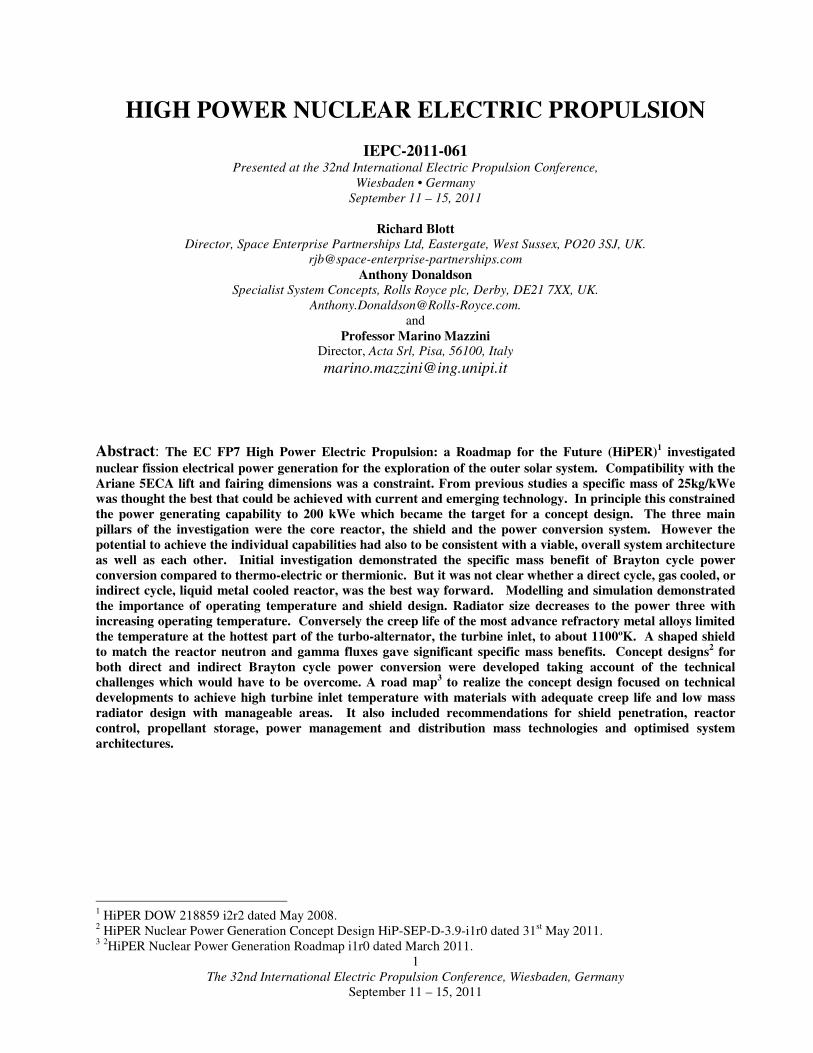
With this operating temperature constraint for the direct cycle (illustrated in Figure 5) the lowest radiator mass was
achieved with a two-staged compressor and free power turbine arrangement. This facilitated the optimisation of
component efficiencies whilst permitting the alternator to run at an appropriate speed for the production of 200kWe
between two ‘pods’. It is thought that the radiator for such a cycle would have a total weight of 3.5 tonnes assuming the
use of tubes of 0.5mm wall thickness for reasons of manufacturability.
The indirect cycle, (illustrated Figure 6), was found to be inherently more efficient than the direct cycle, and
achieved an 11% lower radiator mass calculated through scaling the idealised area. The optimum turbo-machinery
configuration was achieved by employing a two-shaft compressor with a reheat loop driving a free power turbine. The
reheat loop increases the temperature of the fluid entering the free power turbine and consequently the temperature of
the fluid at the radiator inlet. It is thus a direct product of the reheat loop that is responsible for the reduction in mass of
the radiator when compared to the direct cycle.
~
Radiato
r Recuperator To/From
Core
Turb
2x
Comp
Free
Power
Turbine
Outer
Pressure
Vessel
Alternat
or
Radiato
Figure 4: Layout of the direct cycle Power Conversion Unit and associated modules
Recuperator
Alternator
FPT Module
Gas Generator
30
cm
30
cm
40
cm
90
cm
Φ 50 cm
Volute

The 32nd International Electric Propulsion Conference, Wiesbaden, Germany
September 11 – 15, 2011
7
The heat exchanger for the indirect cycle was not thoroughly investigated as it was not seen as being the main
limiting component of the power conversion unit. However, it is anticipated that any heat exchanger design will also be
limited by its creep behaviour and the materials employed to achieve a ten year mission life. Further analysis and
detailed design work is recommended in this area with regards feasibility and potential for material developments by
2020.
2. High Temperature Turbine Design Improvements
The main recommendations for design improvements were to investigate means of achieving higher temperature
turbine operation and different radiator design concepts.
Turbine Inlet Design
The turbine rotor rather than the guide vanes is the vulnerable component. When it is rotating the rotor experiences
a lower stagnation temperature because of the relative motion of the turbine blades to the coolant gas (RD10) as
illustrated in Figure 20 below. Indicative calculations suggest the drop in stagnation temperature could be between ~
80ºK, or higher, thus permitting the reactor outlet temperature to rise to 1180 to 1300ºK.
Turbine Blade Cooling
Another possibility is to bleed cooler coolant gas from the compressor onto the turbine rotor. It is understood that
there has been research in Russia for applying this technique to high temperature terrestrial gas turbines as an
alternative to fabrication from very expensive alloys containing Rhenium. The technique may enable the turbine blades
to remain at up to 200ºK below the temperature of the inlet gas.
Refractory Metal Alloys
There is understood to be a great deal of research into high temperature refractory metal alloys (niobium,
molybdenum, tantalum, tungsten and rhenium) in Europe, Russia and the US. It is also understood that longer creep
life to reduce maintenance in, for example jet engines, is the subject of new research. Extrapolation of creep test results
from 10,000 hour tests to a 100,000 hour design life would probably be necessary to evaluate the potential of these
alloys to meet the high temperature turbine requirements. Niobium, for example, has lower density and should not be
susceptible to oxidation when operating in a xenon and helium environment provided there was adequate protection
from any out-gassing of oxygen in the system. Tungsten has a higher melting point (and therefore onset of creep) but
the higher density makes it more prone to stress. In terrestrial applications the alloys are often coated with materials to
To/From
Radiato
~
To/From
Core
Lithium
Circuit
Recuperator
Turbine
2x
Comp.
Free Power
Turbine
Outer
Pressure
Vessel
(lengthened to
accommodate
2 x IHX)
IHX
IHX Preheater
Radiator
Alternato
r
Figure 5: Layout of the indirect cycle Power Conversion Unit and associated modules
Recuperator
Alternator
FPT Module
Gas Generator
30
30
40
90
Φ 50 cm
IHX Reheater
IHX Preheater
15
15

The 32nd International Electric Propulsion Conference, Wiesbaden, Germany
September 11 – 15, 2011
8
prevent oxidation. This is an expensive process. Although oxidation may not be an issue the ability of suitable
coatings to provide thermal insulation may also be worth investigating.
Ceramic Materials.
Ceramic materials in theory have the thermal and creep properties to offer a very high temperature solution but they
tend to be prone to stress fracture. Another possible line of investigation is a thin ceramic layer on the turbine to give a
highly efficient thermal barrier. This technique is used successfully in terrestrial applications but whether it can be
adapted to radial machinery with the necessary creep life requires further investigation.
3. Fixed Radiator Design Improvements Heat Sink Properties
The Rolls Royce fixed radiator heat sink design is based on a stainless steel or Inconel 600 or 718 (nickel alloy)
simple tube arrangement taking up part or the whole of the cylindrical length of the Ariane 5 fairing (10m). The
material has a density of 8250 kgm-3
and a conductivity of 19 wm-1
K-1
which causes a significant mass penalty. The
original assumption of a 1100ºK turbine inlet temperature required a radiator inlet temperature of 640 ºK, outlet of 420
ºK and mean of 530 ºK for Direct Cycle (inlet 694 ºK, outlet 405 ºK and mean 555 ºK for Indirect Cycle).
The radiator calculations assumed a total cycle pressure drop of 5% of the upper working pressure equivalent to 1
bar total. The radiator tubes are allowed 20% of this budget (0.20 bar) and are limited to using a minimum tube
diameter of between 7.5 and 10mm outside diameter. An assumed 20MPa hoop stress limit corresponds to a wall
thickness of between 0.18mm and 0.24mm. Under these circumstances the tube weight alone amounts to between 1.1
and 1.5 tonnes without any allowance for headers, connecting pipework or supporting structure.
Although it has not been possible to find any evidence of space radiator design to date with these features the design
concept is considered realistic. Compatibility with higher operating temperatures requires further research. For a 1200
ºK the range would rise to inlet 800 ºK, outlet 505 ºK and mean 655 ºK for Indirect Cycle; for 1300 ºK the range would
rise to inlet 840 ºK, outlet of 620 ºK and mean of 730 ºK for Direct Cycle; and for 1500 ºK the range would rise to inlet
1040 ºK, outlet of 820 ºK and mean of 930 ºK for Direct Cycle.
High temperature carbon-fibre tubing can offer comparable thermal and structural properties for specific mass ~
1750 kgm-3
. Although not helping to reduce the required area the lower mass benefits could be significant. (Rough
estimates suggest > 1000 kg mass saving on a 1300 ºK, 200 kWe Direct Cycle system.) On its own, carbon- fibre is
porous to the helium coolant gas so it would be necessary to find some method of sealing against this. If a thin metal
liner was used, for example, the composite density could rise to ~ 2500 kgm-3
but still give significant mass savings. A
500 kg radiator mass saving reduces a 200 kWe generator specific mass by 2.5 kg/kWe and merits further research into
the use of these materials.
Micro-Meteoroid Protection
Micro-meteoroid protection design creates a gap between the outer skin and the surface to be protected. The very
high velocity of impact will vaporise the micro-meteoroid and the thermal energy generated is dissipated in the gap.
The gap does not have to be very wide provided there is sufficient space for the dissipation without further damage.
Coolant carrying tubes have to be protected because a leak would be catastrophic but other structures such as radiating
fins can tolerate most likely impacts. A small vacuum filled gap between the radiator tubes and the space environment
will reduce the radiating efficiency and fins require a larger area to radiate the same quantity of heat.
For a design-case micrometeorite size and velocity, the barrier tube wall thickness should be optimised to vaporise
the micrometeorite. The barrier tube diameter should be optimised to permit the vapour cloud to expand so that the
micrometeorite momentum is dispersed over an area that will not be punctured. The optimum barrier tube diameter
might possibly be much less than the pressure tube diameter.
A fixed radiator for a direct cycle 200 kWe generator with 1300 ºK inlet temperature requires an area of 110 m
2
which will fit within cylindrical section of the Ariane 5 ECA fairing (140 m2) without micro-meteoroid protection.
Rolls Royce proposed a system of micro-meteoroid protection based on a ‘bumper’ shield of smaller empty tubes to
protect the coolant containing tubes (see figure 6 below). The appropriate number of pressure tubes for acceptable gas
pressure drop appears to be in the range from 500-700 for tubes of about 15mm diameter up to 1000-1400 for tubes of
about 10mm diameter. Temperature loss across the barrier is dependent on the ratio of barrier tube thickness to the
square of barrier tube diameter (as well as on metal thermal conductivity). There is an incentive to minimise barrier
tube diameter, so far as the meteorite defence requirement permits while retaining good thermal conductivity.

The 32nd International Electric Propulsion Conference, Wiesbaden, Germany
September 11 – 15, 2011
9
It was estimated that this arrangement would increase the radiator area by ~ 30%, to account for the lower thermal
efficiency of the design, increasing the required area to ~143 m2
(For a 1300ºK Direct Cycle system). The 140 m2
constraint would restrict the generator output to about 195 kWe unless other cooling surfaces could be used. It was also
estimated that there would be a 70% increase in mass (from 1523 to 2589 kg) both for the larger area and the additional
‘bumper’ tubes. These are very severe penalties and to overcome them the following options should be considered in
addition to lower density materials to the coolant carrying tubes themselves:
� Could the bumper tubes be made of low density, high radiative materials such as carbon fibre?
� Can a self sealing mechanism be built into the radiator design so that any coolant tube which is penetrated can
be immediately isolated (if so would one consider a number of redundant coolant tubes)?
� Rather than between tubes could the fins (made with a carbon fibre low mass material) be shaped to curl around
the coolant pipes thus providing the required gap with minimal decrease in radiated heat (see also Figure 6)?
Figure 6: Tube Radiator with Bumper Tubes or Shaped Fin Design.
4. Deployed Radiator Design Improvements
Heat Sink Properties
A NASA has researched a deployed radiator design for a 200 kWe Brayton cycle nuclear generator11
(see Figure 7).
Figure 7: NASA Deployable Radiator Design.
The design is based on heat pipes separated by cooling fins. The heat pipes are ‘fed’ from a circulating coolant
which might be water or potassium. Heat is transferred from the xenon and helium turbo-machinery operating gas in a
heat exchanger. This isolation from the primary (or secondary for the Indirect Cycle) coolant means that rupture of the
radiator coolant main could probably be limited to a wing or even a panel and would not necessarily be catastrophic.
11
NASA/TM—2006-214121 A Comparison of Coolant Options for Brayton Power Conversion Heat Rejection Systems
by John Siamidis (Analex Corporation) and Lee S. Mason (Glenn Research Center) June 2006
The 32nd International Electric Propulsion Conference, Wiesbaden, Germany
September 11 – 15, 2011
10
The resulting design requires a much larger area (two wings of ~165 m2), as shown in Figure 7, than a fixed radiator but
it can be made from lower density materials (~3 kg/m2).
However there is the added vulnerability from all the flexible connections which must survive the radiator
deployment and the complexity of a secondary or tertiary (Indirect Cycle) coolant circuit. More challenging is how to
fit the radiator within the Ariane 5 ECA fairing once space has been allocated to the reactor, shield, conversion
machinery, PMAD, EP Systems, Propellant Storage and structure. The panels in the example are longer than will fit
within the cylindrical section even if it is empty and the overall ~330m2 required for a 200kWe 1200ºK turbine inlet
temperature design represents a significant packaging challenge.
The NASA design appears to be consistent with a shadow angle of less than 10º which will lower shield mass but
implies a longer boom length and associated harness mass. With a 14º shadow angle a comparable boom length to the
concept design should be possible if the radiator can start immediately behind the shield. On this basis it is assumed
that the area and mass in the NASA design are appropriate for a 1200 ºK turbine inlet temperature and some modest
reductions may be expected if the inlet temperature is raised to 1300 ºK.
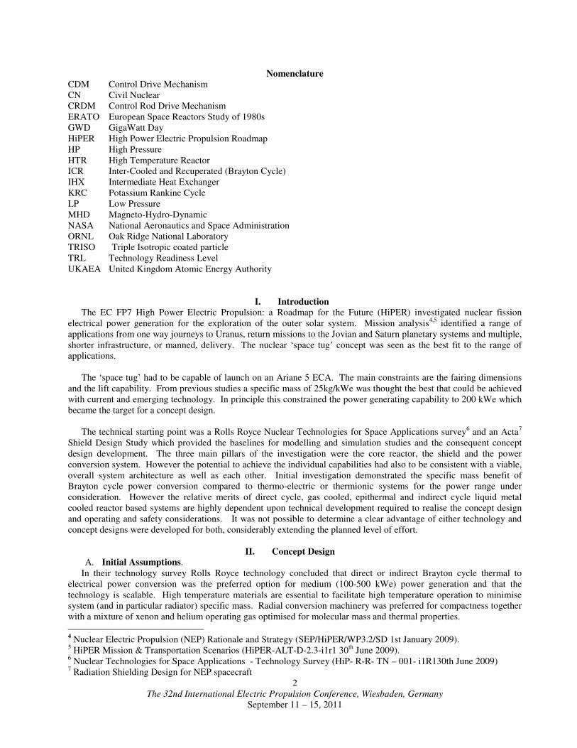
Micro-Meteoroid Protection.
Micro-meteoroid protection is achieved by surrounding the coolant circulating pipes with an outer protection layer
and using the heat pipes for heat rejection as illustrated in Figure 8. The low mass carbon fibre fins between the heat
pipes may be punctured by micro-meteoroids with minimal effect on performance. The heat pipes themselves are
protected by a foam surround and the circulating coolant is protected by foam and an air gap.
Figure 8: Deployable Radiator Design Detail.
E. Operating Constraints and Safety
1. Operating Constraints
In addition to the constraints imposed by the Ariane 5 ECA fairing dimensions and lift capability, core reactivity
control and high temperature materials, the following were also taken into account in the concept design:
� Rotating machinery must be in balanced contra-rotating pairs to avoid inducing unwanted torques,
� The battery (or alternative) power required for initial commissioning and a ‘cold start’ in space if required; the
battery may also have a useful role in helping to protect the system from large transients,
� Resilience to sudden, large load induced transients and emergency shut down,
� Standby and low power operation,
� Reliability, damage control and disposal.
2. Reactor Radiation and Electric Propulsion Thruster Plumes
The principal interfaces are with the structure, including the payload, the PMAD and the environment. The latter
may be taken to include avoiding impingement from EP thruster exhaust plumes. Key considerations were:
� The structure must be sufficiently strong to support the high mass reactor and shield high up in the launcher
fairing during the launch. Although the proposed structural layout has this requirement in mind, structural design was
outside the scope of the study. In principle any fixed radiator for the nuclear power generator is contained in the

The 32nd International Electric Propulsion Conference, Wiesbaden, Germany
September 11 – 15, 2011
11
cylindrical dimensions permitted by Ariane 5 and the remaining conical section is for cooling electrical equipment.
� Electrical power systems and components in the 200kWe range still have to be developed for space applications.
A 500V or possibly 1kV DC power bus appears to be most suited to the EP system requirements. A rectified supply of
this nature is therefore assumed for each generating pod.
� The main environmental consideration is the protection of the spacecraft, and in particular the payload from
radiation. The EP thrusters are most efficient if the thrust vector is through the centre of mass in the direction of the
required motion.
3. Safety
Safety considerations are based on those for the US SP100 project.
III. System Specific Mass Design Targets
A. Design Improvement Recommendations
Recommendations to improve the Concept Design, to achieve the nominal specific masses in Figure 9, were:
Common to both Direct and Indirect Cycles
� Higher turbine inlet temperature (Direct to 1300ºK and investigate 1500ºK; Indirect to 1200ºK),
� Increasing turbine efficiency from 85% to 88%,
� A higher temperature radiator,
� Reducing the mass and volume penalties of micro-meteoroid protection,
� Efficient routing of coolant pipes around, and design of Control Drive mechanisms (CRDM) through, the shield.
Direct Cycle
� Reduce reactor core size through a combination of higher operating pressure, increased TRISO particle density,
and replacing control drums with rods to reduce the overall area required for the passage of coolant gas,
� A narrower shield shadow angle if radiator dimensions and internal pod location permit.
Indirect Cycle
� Increasing core exit temperature to 1200ºK (with high temperature heat exchanger (IHX)),
� Investigating ‘hot launch’ strategies to reduce commissioning power requirements.
SYSTEM & BASELINE EXAMPLE
Recuperated
Brayton
(Epi)
Indirect
Brayton
(Fast)
T hot, ºK 1300 1200
Power
MWth
MWe
1.18
0.200
1.12
0.200
η 0.169 0.175
Reactor Mass kg 1627 8.14 528 2.64
Shield kg 800 4.0 600 3.0
Reactor Control kg 42.6 0.21 31.1 0.16
IHX kg 366 1.83
Generation kg 1656 8.28 1612 8.06
Radiator Area m
2
Mass kg
110
1523 7.62
128
1770 8.85
Total Mass 5648 4907
Sp. Mass, kg/kWe 28.2 24.5
Figure 9. Nominal Best Performance for Direct and Indirect Brayton Cycle Systems (Italics are specific mass).
B. System Concept Design Scaling
Scaling rules were developed for a range from 50 kWe to 2MWe based on a single system; a combination of several
200 kWe systems, for example would still have the same specific mass as a single 200 kWe system.

The 32nd International Electric Propulsion Conference, Wiesbaden, Germany
September 11 – 15, 2011
12
1. Indirect System
Scaling values for the Indirect Brayton cycle design operating at 1200ºK turbine inlet temperature, assuming a mix
of design and material improvements, are in Figure 10 below.
SYSTEM EXAMPLE Recuperated, Reheated Indirect Brayton Cycle
T hot, K 1200
Power
MWth
MWe
0.559
0.100
0.838
0.150
1.117
0.200
11.17
2.0
η 0.179 0.179 0.179 0.179
Reactor Mass kg 438 4.38 485 3.23 528 2.64 1785 0.89
Shield kg 441 4.4 5.27 3.5 600 3.0 1765 0.88
Reactor Control kg 25 0.25 28.3 0.19 31.1 0.16 76.8 0.04
IHX kg 266 2.66 317 2.11 366 1.83 1988 0.99
Generation kg 1204 12.04 1414 9.43 1612 8.06 7350 3.68
Radiator
Area m2
Mass kg
63.7
929 9.29
95.6
1355 9.04
127.5
1770 8.85
1275
15095 7.55
Total Mass kg 3303 4126 4907 28060
Sp. Mass, kg/kWe 33.0 27.5 24.5 14.0
Figure 10. Recuperated, Reheated Indirect Brayton Cycle Optimal Scaling (Italics are specific mass).
Although the Indirect system design appears to meet the target specific mass of 25kg/kWe at 200kWe there are
several factors which must be taken into consideration. Armouring the radiator with a bumper tube design will
increase the volume to 166m2 and the mass to 3009kg. Not only will this not fit within the Ariane 5 fairing; the specific
mass increases to 30.73kg/kWe. If one also adds ~400kg of battery for cold start and commissioning this rises to
32.73kg/kWe. A deployable radiator design would have an area of ~ 330 m2 and approximately 1800kg mass which
with the additional battery suggests specific mass ~26.5kg/kWe might be achievable. This assumes that the PMAD,
electric propulsion system, structure and propellant specific mass contributions are common to all the design options.
2. Direct System 1300ºK
Scaling values for the Direct Brayton cycle design operating at 1300ºK turbine inlet temperature, assuming a mix of
design and material improvements, are in Figure 11 below.
SYSTEM EXAMPLE Recuperated Brayton Cycle
(Epithermal)
T hot, K 1300
Power
MWth
MWe
0.592
0.100
0.888
0.150
1.183
0.200
11.83
2.0
η 0.169 0.169 0.169 0.169
Reactor Mass kg 1226 12.26 1436 9.57 1627 8.13 6468 3.23
Shield kg 598 5.98 708 4.7 800 4.0 2306 1.15
Reactor Control kg 33 0.33 38.3 0.25 42.6 0.21 113 0.06
IHX kg
Generation kg 1229 12.29 1449 9.66 1656 8.28 7693 3.85
Radiator
Area m2
Mass kg
55.1 780 7.80
82.6 1166 7.77
110.1 1523 7.62
1101.3 12997 6.50
Total Mass kg 3886 4797 5648 29578
Sp. Mass, kg/kWe 38.9 32.0 28.2 14.8
Figure 11. Direct Brayton Cycle Optimal Scaling at 1300ºK(Italics are specific mass).

The 32nd International Electric Propulsion Conference, Wiesbaden, Germany
September 11 – 15, 2011
13
A bumper armoured radiator would have an area of 143m2, which only marginally exceeds the cylindrical volume
available in the Ariane 5 fairing but would have a mass of ~ 2589kg, bringing the specific mass up to 33.57kg/kWe. A
deployable radiator could possibly reduce this to 29.15Kg/kWe and a low mass fixed radiator (specific mass 3.8
kg/kWe) could in theory bring the system specific mass down to at 200kWe ~27kg/kWe.
3. Direct System 1500ºK
Scaling values for the Direct Brayton cycle design, assuming ceramic turbines and bumper tube micro-meteoroid
protection, operating at 1500ºK turbine inlet temperature are in Figure 12 below.
SYSTEM EXAMPLE Recuperated Brayton Cycle: Ceramic Turbines and Micrometeorite
Armour. (High Core Exit Temperature)
T hot, K 1500
Power
MWth
MWe
0.592
0.100
0.888
0.150
1.183
0.200
11.83
2.0
η 0.169 0.169 0.169 0.169
Reactor Mass kg 1226 12.26 1436 9.57 1627 8.13 6468 3.23
Shield kg 598 6.0 708 4.7 800 4.0 2306 1.15
Reactor Control kg 33 0.33 38.3 0.25 42.6 0.21 113 0.06
IHX kg
Generation kg 1229 12.29 1449 9.66 1656 8.28 7693 3.85
Radiator
Area m2
Mass kg
40.5
750 7.50
60.6
1098 7.32
80.8
1441 7.21
808
12768 6.38
Total Mass kg 3856 4729 5566 29349
Sp. Mass, kg/kWe 38.6 31.5 27.8 14.7
Figure 12. Direct Brayton Cycle Optimal Scaling at 1500ºK(Italics are specific mass).
This emphasises the benefits of very high temperature operation. The heat exchangers for a deployable radiator
would be technically very challenging. However, a low mass fixed radiator (3.6kg/kWe) might reduce the overall
specific mass at 200 kWe to ~ 24.3kg/kWe.
IV. Roadmap Objectives
A. Nuclear Power Generator
The system design specific mass target analyses illustrate clearly the rationale for the roadmap focus on high
temperature turbine and low mass radiator development. However validation of the technical development required to
achieve power conversion efficiency and compact, high temperature reactor control systems and coolant pipe routing
are all necessary. The advanced shielding design is a very significant contributor to lowering the overall specific mass
also requiring validation through breadboarding and prototyping.
In addition a number of overall system design issues which impact on the nuclear power generator are considered as
described below.
B. Electrical System Design Constraints
1. Power Management and Distribution (PMAD)
Rolls Royce estimated a 40kWhr battery would be needed to commission a Direct Cycle reactor. With the most
advanced space battery technology this will have a mass of ~ 250kg. The task of melting the metal coolant in an
indirect cycle reactor could possibly take up to about 100 kWhr from a cold launch condition and require a
battery mass of ~600kg. An important trade-off to be investigated is the capacity of the large battery to act as a
’shunt’ in the event of a sudden loss of electrical load. It may also bring other benefits but it is a significant
factor in the trade off between the direct and indirect cycle system designs.

The 32nd International Electric Propulsion Conference, Wiesbaden, Germany
September 11 – 15, 2011
14
2. Electric Propulsion PPUs
Very little information exists on PPU characteristics because space qualified components to operate at these high
powers do not currently exist. Although this subject lay outside the scope of this particular study the interface
must be included in future research and development because it is a critical consideration in the reactor
emergency shut down design. There is, for example, a significant trade-off in the mass and capacity of a coolant
by-pass in the turbo-alternator to that of a shunt to absorb a sudden fall in electrical power demand.
C. Propellant Storage, Spacecraft Centre of Mass and Architecture
1. Propellant Storage
It was assumed that xenon propellant will stored in a supercritical condition at about 300ºK giving it a density of
~1100 kg/m3. This can provide a useful shielding effect until the propellant is used. This could probably be
maintained at a modest pressure between 30 and 90 Bar for much of the mission. If advantage is to be taken of this the
tanks need to be designed to minimise streaming through the gaps between them and an arrangement of 4 relatively
wide diameter, say 1.5 metres, would need to be less than 0.5 metres long to hold 4 tons of propellant. If these were
located at the separation plane they could make a useful counterbalance to the reactor and shield when establishing the
centre of mass.
At these pressures the tanks could be made of relatively low mass material. Although the tanks themselves will not
contribute directly to the structural integrity of the spacecraft the role of their supporting structures should be taken into
consideration. Maintaining the propellant within reasonable temperature limits must also be considered.
2. Centre of Mass for Launch and Operations
The Ariane 5 ECA constraint of a payload centre of mass 2.5 metres above the separation plane may also prove to
be significant. Two of the heavier elements, the reactor and shield, are at the top end of the fairing. To some extent
concentrating the propellant tanks at the base of spacecraft can help to counter this. A smaller radiator can have a
centre of mass closer to the base but does less to counterbalance the reactor and shield. In addition it may be necessary
to site turbo-alternator pods, the PMAD and PPUs further away from the reactor. Extending the length of cooling pipes
is unattractive, especially if it leads to a greater pressure drop in the gas cooled Direct Cycle system. Once the
individual system mass budgets are finalised the overall centre of mass will need to be reviewed. Relaxations to this
constraint should also be sought with the launch provider.
3. Architecture and Structure Thermal and Structural Integrity
The overall structural and thermal integrity of the spacecraft falls outside the scope of this study. However the
design of the nuclear generator can only be optimised by analysis of the trade-offs between the other elements of the
spacecraft and consideration of structural and thermal constraints. The issues have been highlighted in this study and in
many cases suggestions made for the way forward. It is considered that there is sufficient information now to conduct
an analysis of the architecture and structural and thermal integrity.
V. Conclusions and Recommendations
Very challenging design targets for nuclear power generation were set in the HiPER Study. The technical
developments to approach, and possibly achieve, the targets was identified and a Road Map developed to realise them.
The modelling and simulation which underpins the work was constrained by the Ariane5 ECA lift and fairing volume.
However the scaling laws developed permit the design objectives to be relevant to Brayton cycle nuclear power
generator development in the range 50kWe to 2MWe.
The scale of development required is probably too challenging for current budgetary pressures in Europe alone. It is
therefore recommended that the way ahead proposed in the Road Map is considered as a basis for a wider scale
international cooperative development.