high performance transistor inverter vector …october, 1996 part #42709-001 high performance...
TRANSCRIPT

October, 1996Part #42709-001
HIGH PERFORMANCE TRANSISTOR INVERTERVECTOR DRIVE SERIES
RS232C COMMUNICATIONS MANUAL
efesotomasyon.com -Toshiba inverter,drive,servo,plc

- 1 -
IntroductionThank you for purchasing the Toshiba TOSVERT-130 G3 High-Performance Transistor Inverter withbuilt-in RS232C serial communications. Before using the RS232C communication features, pleasebe sure to thoroughly read the instructions and precautions contained in this manual. In addition,please make sure that this instruction manual is delivered to the end user of the inverter unit, andkeep this instruction manual in a safe place for future reference or inverter inspection.
This instruction manual describes the communication specifications, wiring, protocol, functions andusage methods for the RS232C communications interface.
efesotomasyon.com -Toshiba inverter,drive,servo,plc

- 2 -
Usage Precautions
• Do not touch charged parts such as the terminal block while the inverter’s CHARGE lamp is lit.A charge will still be present in the inverter unit’s internal electrolytic capacitors, and thereforetouching these areas may result in an electrical shock. Always turn all inverter input powersupplies OFF, and wait at least 5 minutes after the CHARGE lamp has gone out beforeconnecting the communications cable or motor wiring.
• To avoid the possibility of electric shock due to leakage currents, always ground the inverterunit’s E/GND terminal and the motor.
• When making wiring connections, make certain that no clippings or wiring leads that couldcause device failure fall into the inverter or onto electronic components.
• Route the communications cable separate from the inverter input/output power wiring.
• The inverter’s EEPROM has a life span of 10,000 write cycles. Do not write to the sameEEPROM address (bank 1) more than 10,000 times.
• When the inverter’s control power supply is turned on, the inverter performs initializationfunctions for approximately 1 second, during which communications capabilities are disabled.Communications capabilities will also be disabled for approximately 1 second after momentarycontrol power supply outages or inverter resets.
• Do not make any connections to the +5v pin (pin #5) on the inverter’s RS232C port (CN4) - thispin is the power source for the optional parameter writer unit. If connections are made to thispin, the inverter may cease to function properly or the inverter unit may be damaged.
• Do not plug in or remove the RS232C communications cable into the inverter’s CN4communications port while power is applied to the inverter. If the cable is plugged in orremoved while power is applied, the inverter’s main control board may be damaged.
Usage Precautions
efesotomasyon.com -Toshiba inverter,drive,servo,plc

- 3 -
Table Of Contents
1. Wiring Connections......................................................................................................... 4
2. Overview.................................................................................................................... ....... 5
3. Host Computer ↔↔↔↔ Inverter Data Exchange Process ..................................................... 6
4. Communications Format................................................................................................. 74.1 Data Transmissions From Host Computer To Inverter .................................................. 74.2 Data Responses From Inverter To Host Computer ....................................................... 8
5. Transmission Commands ............................................................................................. 105.1 Command Summaries ................................................................................................ 11
6. Communication Examples ............................................................................................ 156.1 Communications Preparation...................................................................................... 156.2 Timer Function............................................................................................................ 166.3 Examples.................................................................................................................... 176.4 Address Increment Function Examples....................................................................... 19
7. Example Communication Programs............................................................................. 20
8. Appendix .................................................................................................................... .... 278.1 Communications Specification.................................................................................... 278.2 Communication Errors ................................................................................................ 298.3 Memory Configuration................................................................................................. 318.4 Communications Data Tables ..................................................................................... 338.5 ASCII Character Codes .............................................................................................. 638.6 Notes .......................................................................................................................... 64
efesotomasyon.com -Toshiba inverter,drive,servo,plc

- 4 -
1. Wiring Connections
The built-in RS232C serial communications port (CN4) is located on the lower half of the main controlboard. The connector is a modular 6-pin phone-jack type (part number TM3P-66P, made by HiroseElectric). A typical connection configuration between a G3 inverter and a standard personal computerwith a 9-pin RS232C serial port is shown in Figure 1. Because communication interfaces and signal-control programming methods vary, however, this configuration may need to be modified on a case-by-case basis for non-standard interfaces.
G3 Inverter RS232C Serial Port (CN4) Pin Definitions
Pin # Name Function1 RTS request to send (output)2 TxD transmit data (output)3 SG signal ground / common return4 RxD receive data (input)5 +5V power supply for parameter writer unit (NOTE)6 CTS clear to send (input)
(NOTE): Do not make any connections to the +5V pin (pin #5) - this pin is to be used only as thepower source for the optional parameter writer unit. If connections are made to this pin, theinverter may cease to function properly or the inverter unit may be damaged. Also, to avoiddamaging the inverter’s main control board, do not plug in or remove the RS232Ccommunications cable while power is applied to the inverter.
(15m m axim um )
(DB -9 back-side view )
C N4
G 3 InverterC om puter (DB -9)
C D
D TR
D SR
C TS
R TS
R xD
TxD
SG
R xD
SG
⑨⑧⑦⑥⑤④③②①
1
4
6
8
7
3
2
5
1
6
2
4
35
TxD
C TS
R TS
+5V
❻ ❺ ❹ ❸ ❷ ❶
Figure 1. Typical Connection Configuration
efesotomasyon.com -Toshiba inverter,drive,servo,plc

- 5 -
2. Overview
The inclusion of RS232C serial communications as standard on the TOSVERT-130 G3 high-performance transistor inverter provides a wide spectrum of inverter control, status and parametersetting capabilities when connected to a computer (host). A program can be written on the hostcomputer that controls communication from the computer to an inverter, processing and analysis ofthe inverter’s response, and formatted display of the response data. In the same way, this type ofprogram can allow a complete set of inverter parameter data to be read and saved onto a storagedisk, and then edited or uploaded to other inverter units. Some example RS232C functions and theinternal access locations associated with them are as follows:
• Monitor functions (output frequency, load current, input voltage, etc.)❈ read from RAM (word/bit ✳1)❈ read from EEPROM (word/bit ✳1)❈ read from internal ROM (word/bit ✳1)❈ read from external ROM (word/bit ✳1)❈ read from the option bus (word/bit ✳1) ✳2
• Command functions (RUN / STOP, JOG, etc.)
❈ read from / write to RAM (word/bit ✳1)❈ simultaneously write to both EEPROM and RAM ✳2 (word/bit ✳1)❈ read from EEPROM (word/bit ✳1)
• Parameter functions (parameter data setting reading / writing)
❈ read from / write to RAM (word/bit ✳1)❈ read from / write to EEPROM (word/bit ✳1)❈ simultaneously write to both EEPROM and RAM ✳3 (word/bit ✳1)
• Additional functions❈ communications timer function can detect broken cables, etc.❈ address increment function can automatically increment the address after reads/writes.
Notes✳1: Individual bit read/writes can be performed by setting the data mask. When the data mask is
used, bits that are masked off are read as “0”, and are not changed when written to (refer tothe mask setting command in section 5.1.)
✳2: When reading from the option bus with a TOSLINE-F10, TOSLINE-S20, DeviceNet or RIOcommunications option board installed, the option board’s dual-port RAM is accessed. Whenreading from the option bus with an RS485 communications option board installed, the optionboard’s USART serial controller is accessed.
✳3: When writing to EEPROM addresses 03C0H ∼ 04FEH (excluding 04D8H ∼ 04F7H), both theEEPROM and RAM are written. When writing to all other addresses, only the EEPROM iswritten.
★ Throughout this document, the term “bit” will refer to the smallest computer data element, andwill be represented as either a “0” or “1”. Similarly, 8 bits will be referred to as a byte, and 16bits (2 bytes) will be called a word.
efesotomasyon.com -Toshiba inverter,drive,servo,plc

- 6 -
3. Host Computer ↔↔↔↔ Inverter Data Exchange Process
(1) The inverter waits for a request from the host computer to establish a computer link.
(2) The inverters ignore all characters received before a “(“ character. If multiple “(“ characters arereceived, only the last one received is valid, and all others are discarded.
Ex: HOST COMPUTER → INVERTER INVERTER → HOST COMPUTERW%3R(A03C0) (A03C0)
(3) When an inverter number is included after the “(“ character, only when that number correspondsto the inverter’s number will the transmission be valid. If the number does not correspond, theinverter will disregard the transmission without sending any response, and will wait for the next “(“character.
(4) When an inverter number is not included after the “(“ character, the transmission is regarded asvalid, and the inverter will accept the command.
(5) Only when a carriage return code (0DH) is received will the transmission be consideredterminated. If the transmitted message exceeds the maximum number of characters allowed(14), a communications error (error code 0001) is generated.
(6) If the inverter’s communications timer is set, and if a transmission is not received within the settime, a communications error will be generated and the inverter will trip (LCD display will show“COMMUNICATION ERROR (PRESS CLEAR)”). (Standard shipment setting for thecommunications timer is “OFF” (0), so if the timer is to be used, the timer time must be set. Formore information on setting the communications timer, refer to section 6.2 Timer Function).
(7) If the message does not correspond to the format described in section 4. CommunicationsFormat, a communications error will be generated.
(8) After the received command is processed, a response is sent back to the host computer. Typicalresponse times (inverter processing time only - not including communication time) withCOMMUNICATION SELECTION in GROUP:COMMUNICATION SETTING PARAMETERS set to 0(standard shipment setting) are on the order of 3.9ms to 5.9ms. Data write commands, however,may take upwards of 9.7ms to 11.7ms under the same conditions. In addition, ifCOMMUNICATION SELECTION in GROUP:COMMUNICATION SETTING PARAMETERS is setfrom 1 ∼ 3 (RS485, TOSLINE-F10, TOSLINE-S20, DeviceNet or RIO boards installed), the timeranges for these operations may be lengthened by up to a factor of 3 times those given above.
NOTE: When the inverter’s control power supply is turned on, the inverter performs initializationfunctions for approximately 1 second, during which communications capabilities aredisabled. Communications capabilities will also be disabled for approximately 1 secondafter momentary control power supply outages or inverter resets.
efesotomasyon.com -Toshiba inverter,drive,servo,plc

- 7 -
4. Communications Format
All data is represented in hexadecimal format, and inverter status data is not included in the responsedata (except for the addition of the “#” character when the inverter is tripped.) All transmittedcharacters conform to the 7-bit (or 8-bit) ASCII (ANSI) standards (refer to section 8.5 ASCII CharacterCodes.)
• If monitoring the inverter status is desired, refer to the status monitor portion of section 8.4Communications Data Tables.
4.1 Data Transmissions From Host Computer To Inverter
1. “(“ (1 character) Header code2. INVNO (2 characters) Inverter number (optional): 00 (30H, 30H) ∼ 99 (39H, 39H) [base 10]. Only when
this number and the inverter number set via the inverter control panel match will the command berecognized. If this number does not match the inverter number, or if this number is only 1character long, the command will not be recognized and no response will be sent.Note: Because the panel setting is in base 10, the transmitted number must also be in base 10.
3. CMD (1 character) Command (refer to section 5.1 Command Summaries) [base 16].
4. DATA (0 ∼ 4 characters) Data (refer to section 5.1 Command Summaries) [base 16].
5. “+” (1 character) Address increment code (optional). Only valid during R/W commands. After theR/W command is performed, the inverter’s address data is automatically incremented by 1 word(address data + 2). (Because the address data is changed, the mask data returns to itsinitialization value of FFFFH).
• If there is no “+” character or if an error occurs, the address and mask data remainunchanged.
6. “&” (1 character) Checksum indicator code (optional). Do not include checksum data when thischaracter is not used.
7. SUM (2 characters) Checksum (optional). ASCII-coded, least-significant 2-digit value (4 bits/digit) ofthe sum total addition of the ASCII code values from the header code to the checksum indicatorcode. Do not include a checksum indicator code when the checksum data is not included.
8. “)” (1 character) Termination code (optional).
9. CR (1 character) Carriage return code.
CR(0DH)
“)“(29H)
“&“(26H)
“+“(2BH)
“(“(28H)
SUMDATAINVNO CMD
Optional
Checksum Limits
OptionalOptional
Optional
1413121110987653 421
efesotomasyon.com -Toshiba inverter,drive,servo,plc

- 8 -
4.2 Data Responses From Inverter To Host Computer
[Normal Condition]
When an inverter number is transmitted, and that number does not match the inverter’s set number,the inverter does not transmit a response to the host computer.
1. “(“ (1 character) Header code
2. INVNO (2 characters) Inverter number: 00 (30H, 30H) ∼ 99 (39H, 39H) [base 10]. If thetransmitted number does not match the inverter number, or if the transmitted number isonly 1 character long, the command will not be recognized and no response will besent.
3. CMD (1 character) Command. The received command is returned.
4. DATA (4 characters) Data. Except for the “R” and “W” commands, the received data isreturned (for the “R” command, the read data is returned, and for the “W” command, thedata after writing is returned.) If the received data was less than 4 characters in length,the returned data is extended to 4 characters (Ex: (B0) → (B0000) ).
5. “+” (1 character) Address increment code. Returned only when initially received. (Onlyvalid during R/W commands. After the R/W command is performed, the inverter’saddress data is automatically incremented by 1 word (address data + 2), and the maskdata is returned to its initialization value of FFFFH.)
6. “&” (1 character) Checksum indicator code. Returned only when initially received.
7. SUM (2 characters) Checksum. ASCII-coded, least-significant 2-digit value (4 bits/digit) ofthe sum total addition of the ASCII code values from the header code to the checksumindicator code (returned only when a checksum indicator code was initially received).
8. “#” (1 character) Inverter tripped code. Only returned when the inverter is tripped.
9. “)” (1 character) Termination code (returned only when initially received).
10. CR (1 character) Carriage return code.
<< Note >> When a reset command is received, the inverter may reset during the responseprocess, resulting in an incomplete response.
CR(0DH)
“)”(29H)
“#“(23H)
“&“(26H)
“+“(2BH)
“(“(28H)
SUMDATAINVNO CMD
Checksum Limits
Only when tripped
Optional
Optional
Optional
151413121110987653 421
Optional
efesotomasyon.com -Toshiba inverter,drive,servo,plc

- 9 -
[Error Condition]
When any of the errors described below occur while a command is being processed, thecommunications error code (N), the error number (refer to section 8.2 Communication Errors), andchecksum data (if initially received), are returned to the host computer. No response will be sent tothe host computer when an inverter number was included in the original transmission but it does notmatch the inverter’s set number, when a format error occurs, or when the correct inverter number wastransmitted but a checksum error occurs, as this could cause bus contention.
“(“ (1 character) Error code.DATA (4 characters) Data (0000 ∼ 0004).
0000 ...cannot execute (communication was correct, but cannot execute command.Typical causes: attempt to write a parameter that cannot be written while theinverter is running (MAXIMUM OUTPUT FREQUENCY, VOLTS PER HERTZPATTERN, etc.), EEPROM error).
0001 ...data error (data setting value outside of adjustment range, data exceeded 4characters, etc.)
0002 ...address error (address data outside of adjustment range when a “W” commandwas sent, etc.)
0003 ...command error (invalid command).0004 ...checksum error (checksum data incorrect).
“)” (1 character) Termination code. Returned even when not initially received.
Examples:(N0000&5C) ........cannot execute (attempt to change MAXIMUM OUTPUT FREQUENCY while the
inverter was running, etc.)(N0001&5D) ........data error (attempt to set a preset speed higher than the UPPER LIMIT
FREQUENCY setting, etc.)(N0002&5E) ........address outside limits (a “W” command was sent with the address data set to
a write-protected area (RAM: address set to less than 3C0H or higher than516H, EEPROM: less than 3C0H or higher than 59EH), etc.)
(N0003&5F) ........command error (command other than A, B, M, R, W, or T sent, etc.)(N0004&60) ........checksum error (checksum data incorrect)no response ..........inverter number error, format error (parity error, overrun error, framing error),
checksum error when an inverter number was transmitted, etc.
CR(0DH)
“)”(29H)
“#“(23H)
“&“(26H)
“(“(28H)
SUMDATAINVNO “N”(4EH)
Checksum Limits
Only when trippedOptional
Optional
1413121110987653 421
efesotomasyon.com -Toshiba inverter,drive,servo,plc

- 10 -
5. Transmission Commands
1) A (41H): address setting command
2) R (52H): read command (word read)
3) W (57H): write command (word write)
4) M (4DH): mask setting command
5) B (42H): bank setting command
6) T (54H): communications confirmation (test) command
• Once set, the address, bank, and mask setting data do not change until they are set to differentvalues, except for the following conditions:
⇒ whenever the address data is changed, the mask data returns to its initialization value ofFFFFH.
⇒ whenever the address increment function is used in conjunction with the “R” or “W”commands, the address data is automatically incremented by 1 word (2 bytes), and themask data therefore returns to its initialization value of FFFFH.
When power is first applied to the inverter unit, or after a reset or trip clear, etc., the following datavalues are initialized:
Address data = 0510H..... (RS232C frequency command setting address)Bank data = 0000H..... (RAM)Mask data = FFFFH.... (all bits can be written to)
Initial Values
efesotomasyon.com -Toshiba inverter,drive,servo,plc

- 11 -
5.1 Command Summaries
[A] Address setting command
Sets the address to be used when reading or writing (refer to the “Address” columns of thecommunications data tables in section 8.4.)
Address Settings (address data limits: 0000H ∼ FFFFH)Bank R/W Read Write
Bank = 0 (RAM)Bank = 1 (EEPROM)Bank = 2 (Internal ROM)Bank = 3 (External ROM)Bank = 4 (Option bus)
R/WR/W
RRR
0100H ∼ 077EH
0000H ∼ 7FFEH
8000H ∼ FFFEH
0000H ∼ FFFEH
0000H ∼ 1FFEH
03C0H ∼ 0516H ✳1
03C0H ∼ 059EH ✳1 ✳2
×××
✳1: The following RAM and EEPROM locations cannot be written to:04D8H ∼ 04F7H, 0500H ∼ 0507H (RAM only), 04FAH bits 4 and 5, 04FBH bit 7, 050AH bits 4 and5 (RAM only), 050BH bit 7 (RAM only), 0512H bits 4 and 5 (RAM only), 0513H bit 7 (RAM only).
Bit position example: (Address 04FAH)
✳2: When addresses 03C0H ∼ 04FEH (excluding 04D8H ∼ 04F7H) are written to, both RAM andEEPROM contents are changed. Writing to all other addresses changes only the EEPROMcontents.
• Once set, the address data does not change until it is set to a different value, except when theaddress increment function is used in conjunction with the “R” or “W” commands, in which casethe address data is automatically post-incremented by 1 word (2 bytes). On power-up or after areset, etc., the address data is initialized to 0510H (RS232C frequency command).
4567 0123 4567 0123
Address 04FAH
04FAH bits 4 and 504FBH bit 7
Address 04FBH
The address data should only be set to a maximum of 1 byte less than the bank’s upperlimit. For example, the read limits of RAM (bank 0) are from 0100 H ∼∼∼∼ 077FH, so if you wouldlike to read from address 077F H, set the address to 077E H and then retrieve the data fromthe upper byte of the response word. If the address were set to 077F H and a read wereperformed, an attempt would be made to access address 0780 H, which is above themaximum address limit.
Caution
efesotomasyon.com -Toshiba inverter,drive,servo,plc

- 12 -
[B] Bank setting command
Sets the type of memory to be accessed (refer to the “Bank” columns of the communications datatables in section 8.4.)
Bank Settings (bank data limits: 0000H ∼ 0004H):0000 ......RAM0001 ......EEPROM0002 ......Internal ROM (read-only)0003 ......External / Option ROM (read-only)0004 ......Option bus (read-only)
• Once set, the bank data does not change until it is set to a different value. On power-up or after areset, etc., the bank data is initialized to 0000H (RAM).
[M] Mask setting command
Allows the access of only the data required during read/write operations. During data writes, datachecking is performed to ensure that the data is being set within adjustment limits, but only thatportion of the data that is within the limits of the mask setting is checked (refer to the “Mask” columnsof the communications data tables in section 8.4.) Mask data limits = 0000H ∼ FFFFH.
When writing data, set the mask bits to binary “1” for those bits that you would like to change, and setthe mask bits to binary “0” for those bits that you do not want to change. When reading data, set themask bits to binary “1” for those bits that you would like to read, and set the mask bits to binary “0” forthose bits that you do not want to read. At read time, all data bits for which the corresponding maskbits are “0” will be read as “0”.
• Once set, the mask data does not change until it is set to a different value or until the addressdata changes. When the address data changes (including when the address-increment functionis used in conjunction with the R/W commands), the mask data is automatically set to itsinitialization value of FFFFH, which allows all bits to be read/written. Upon inverter power-up orafter a reset, etc., the mask data is initialized to FFFFH.
Ex: To set the Command • frequency mode selection to “RS232C commands valid” (refer to page 34):
HOST COMPUTER → INVERTER INVERTER → HOST COMPUTER(B0) (B0000) ..... set bank to RAM(A515) (A0515) ..... set selection address(M3) (M0003) ..... mask = (0000 0000 0000 0011)2
(W1) (W ××××) ..... data depends on other bits
0000 0000 0000 1100
Due to the mask, only these bits can be changed
Address 0515HAddress 0516H
Optional (only the lowest digit is required)
efesotomasyon.com -Toshiba inverter,drive,servo,plc

- 13 -
[W] Data write command
Writes data to the set address in the set bank. When writing to EEPROM addresses 03C0H ∼ 04FEH
(excluding 04D8H ∼ 04F7H), both RAM and EEPROM contents are changed (for data setting limits,refer to the “Adjustment Range” columns of the communications data tables in section 8.4).
• The data response received after sending a “W” command is the actual data at the address afterwriting (word length). This feature combines the write command with the function of the readcommand (see Example #1 below.)
• The write command can only be used with RAM (bank 0) and EEPROM (bank 1).
• Address increment function: if a “+” character is included in the “W” command immediatelyfollowing the data, the address is automatically post-incremented by 1 word (2 bytes), and themask data returns to its initialization value of FFFFH. This feature can be used to write largeblocks of data with a minimum number of commands.
<< Note >>When a data write is performed, only that portion of the data that is within the mask limits is checkedby the data checking routine (see Example #2 on page 14). If the data being written is outside of theadjustment limits associated with that address, an error is generated, and the data is not written.Please be sure to correctly set the mask before performing a data write. If the mask is not correctlyset, the data cannot be correctly checked, which may result in data corruption or unpredictableinverter operation (data checking is not performed on certain parameters: refer to the communicationsdata tables in section 8.4 for further information).
Example #1: Writing RS232C commands (refer to page 34).
HOST COMPUTER → INVERTER INVERTER → HOST COMPUTER(B0) (B0000) ...... set bank to RAM(A512) (A0512) ...... RS232C command address(R) (R0009) ...... acc/dec #2, reverse, running(M4) (M0004) ...... mask forward/reverse selection(W4) (W000D) ...... forward (acc/dec #2, running)(R) (R0004) ...... forward ✳1 (verify data)
✳1: If only whether the inverter is running in forward or reverse is to be determined, the readcommand could be sent immediately after the mask command. Note that the data contained inthe response to the write command is the complete, unmasked data at that address.
The EEPROM has a lifespan of 10,000 write cycles per address. Do not write to the sameEEPROM (bank 1) address more than 10,000 times.
Caution
efesotomasyon.com -Toshiba inverter,drive,servo,plc

- 14 -
Example #2: Setting the frequency display resolution parameter (refer to FREQUENCY DISPLAYRESOLUTION in GROUP:UTILITY PARAMETERS in section 8.4).
HOST COMPUTER → INVERTER INVERTER → HOST COMPUTER(B0) (B0000) ..... set bank to RAM(A45D) (A045D) ..... frequency display resolution address(R) (R3111)(M3) (M0003)(W6) (W3112)
• The adjustmentrange for the frequency display resolution parameter is 0 ∼ 2, but because data checking is onlyperformed on that portion of the data contained in the mask, the written data is viewed as 2. Thisis within the adjustment range and, therefore, no error occurs. The end result is that thefrequency display resolution parameter setting is changed to 2 (0.01Hz).
[R] Data read command
Reads the data at the set address in the set bank. No data argument is required for this command:any included data is ignored.
• The data contained at the set address is returned as the data argument to the host computer. Ifthe mask data is FFFFH, the returned data word is the complete data at the address. If the maskdata is anything other than FFFFH, those bits set to 0 in the mask will be returned as 0’s.
• Address increment function: if a “+” character is included in the “R” command, the address isautomatically post-incremented by 1 word (2 bytes), and the mask data returns to its initializationvalue of FFFFH. This feature can be used to read large blocks of data with a minimum number ofcommands.
[T] Test command
Transmitted data (0 ∼ 9, A ∼ F) is returned unchanged to the host computer. Data adjustment range:0000H ∼ FFFFH.
1100 1000 1000 1000
Address 045DHAddress 045EH
0000 0000 0000 0110
Address 045DHAddress 045EH
1100 1000 1000 0100
Address 045DHAddress 045EH
• Data after write
• Write data
• Mask overlaid on data prior to write
efesotomasyon.com -Toshiba inverter,drive,servo,plc

- 15 -
6. Communication Examples
6.1 Communications Preparation(1) Using the communications cable, connect the G3 inverter and the host computer (refer to section
1. Wiring Connections).(2) Turn power to the inverter and host computer ON.(3) Check that the baud rate, number of data bits, parity, etc. are all set correctly.(4) Run a communications interface application program on the host computer.
Communication should now be possible. The examples that follow were generated with the sampleMS-DOS QBasic RS232 communications program shown in Example #2 of section 7. ExampleCommunication Programs.
(Note) If using the sample program directly, verify that the inverter’s communication parameters (inGROUP:COMMUNICATION SETTING PARAMETERS) are set as follows (standard factorysettings):RS232 BAUD RATE ............. 2 (9600 baud)NUMBER OF DATA BITS..... 0 (7 bits)PARITY SETTING ............... 0 (even parity)
Example: Switching to RS232 command and frequency mode (refer to page 34):
HOST COMPUTER → INVERTER INVERTER → HOST COMPUTER(B0) (B0000) .... set bank to RAM(A515) (A0515) .... set selection address(M3) (M0003) .... mask applicable bits(W3) (W ××××) .... “RS232C command & frequency valid”
• Note that because the RS232C command/frequency mode selection has priority, the setting ofCOMMAND MODE SELECTION and FREQUENCY MODE SELECTION in GROUP:UTILITYPARAMETERS will have no effect on the actual command/frequency status after the aboveexample program is executed. Even if the command/frequency mode is not set to RS232C input,other functions such as parameter setting, inverter status monitoring, etc., can still be performedvia RS232C communications.
efesotomasyon.com -Toshiba inverter,drive,servo,plc

- 16 -
6.2 Timer Function
When using RS232C communications with the G3 inverter, a communications timer function can beimplemented. When the communications timer is used, if communication does not take place withinthe set time limit, the inverter will trip (“COMMUNICATION ERROR (PRESS CLEAR)“ will be shown onthe LCD display).
If it is desired to have the timer function active even after inverter control power is cycled OFF andON, write the timer setting to EEPROM (bank 1). If it is desired to have the timer function disabledafter inverter control power is cycled OFF and ON, write the timer setting to RAM (bank 0). Thefollowing example shows the remaining steps for setting the timer. (NOTE: Because the factorysetting for the timer is 0000H, setting the STANDARD SETTING MODE SELECTION parameter inGROUP:UTILITY PARAMETERS to 3 (return to factory settings) will cause the timer setting to returnto 0000H).
Ex: Setting the RS232C communications timer (setting to 15 seconds):
HOST COMPUTER → INVERTER INVERTER → HOST COMPUTER(A445) (A0445) ..... RS232C timer address(MFF) (M00FF) ..... mask applicable bits(WF) (W××0F) ..... set timer to 15 seconds(R) (R ××0F) ..... activate timer
< Timer adjustment range > 00H : timer OFF
01H ∼ 64H : 1s ∼ 100s
NOTE
• Setting the timer time alone does not activate the timer. The timer is activated by the first validcommunication that occurs after the timer is set. If the timer setting is written to the EEPROM, thetimer is activated by the first valid communication that occurs after the inverter is powered ON.
• If an inverter number error (number is only 1 character long, number does not match the inverter’sset number), format error (parity error, overrun error, framing error), or checksum error when aninverter number was transmitted occurs immediately after the timer time is set, this is not regardedas a valid communication, and the timer will not be activated / reset.
• To turn the timer function OFF, set the timer setting to “0”. The timer will then be turned OFFupon the occurrence of the next valid communication (writing “0” to the timer setting alone will notturn the timer OFF).
efesotomasyon.com -Toshiba inverter,drive,servo,plc

- 17 -
6.3 Examples• Setting the RS232C frequency command value:
HOST COMPUTER → INVERTER INVERTER → HOST COMPUTER(B0) (B0000) ..... select RAM (bank 0)(A510) (A0510) ..... RS232C frequency command address(R) (R1F40) ..... currently set to 80.00Hz(W1770) (W1770) ..... change to 60.00Hz
• Performing RUN/STOP commands:
HOST COMPUTER → INVERTER INVERTER → HOST COMPUTER(B0) (B0000) ..... select RAM (bank 0)(A512) (A0512) ..... RS232C command address(M1) (M0001) ..... mask RUN/STOP bit(W1) (W ××××) ..... execute RUN command(W0) (W ××××) ..... execute STOP command
• Monitoring the command mode status:
HOST COMPUTER → INVERTER INVERTER → HOST COMPUTER(B0) (B0000) ..... select RAM (bank 0)(A5B8) (A05B8) ..... command mode status address(M3) (M0003) ..... mask status bits(R) (R0003) ..... command mode currently = RS232C
• Switching to JOG mode:
HOST COMPUTER → INVERTER INVERTER → HOST COMPUTER(B0) (B0000) ..... select RAM (bank 0)(A512) (A0512) ..... RS232C command address(M80) (M0080) ..... mask JOG mode selection bit(W80) (W ××××) ..... select JOG mode
• Selecting between acc/dec #1/#2 (setting acc/dec #2):
HOST COMPUTER → INVERTER INVERTER → HOST COMPUTER(B0) (B0000) ..... select RAM (bank 0)(A512) (A0512) ..... RS232C command address(M8) (M0008) ..... mask acc/dec #1/#2 selection bit(W8) (W ××××) ..... select acc/dec #2
• Monitoring operating frequency:
HOST COMPUTER → INVERTER INVERTER → HOST COMPUTER(B0) (B0000) ..... select RAM (bank 0)(A524) (A0524) ..... operating frequency monitor address(R) (R1770) ..... inverter is running at 60.00Hz
efesotomasyon.com -Toshiba inverter,drive,servo,plc

- 18 -
• Monitoring the cumulative run time:
HOST COMPUTER → INVERTER INVERTER → HOST COMPUTER(B0) (B0000) ..... select RAM (bank 0)(A5D2) (A05D2) ..... run time rollover bit address(M8) (M0008) ..... mask run time rollover bit(R) (R0000) ..... timer has not rolled over(A5A6) (A05A6) ..... cumulative run time address(R) (R0064) ..... timer is currently at 100 hours
• Executing emergency off command (inverter will trip):
HOST COMPUTER → INVERTER INVERTER → HOST COMPUTER(B0) (B0000) ..... select RAM (bank 0)(A513) (A0513) ..... RS232C command address(M10) (M0010) ..... mask emergency off command bit(W10) (W ××××) ..... execute emergency off
❈ Because the inverter has tripped, all responses from the inverter will have the invertertripped “#” character included until a trip clear command is performed.
• Monitoring the present trip code:
HOST COMPUTER → INVERTER INVERTER → HOST COMPUTER(B0) (B0000#) .... select RAM (bank 0)(A591) (A0591#) .... present trip monitor address
(refer to Table 1 on page 40)(M7F) (M007F#) .... mask trip code bits(R) (R0011#) .... 11H = emergency off trip
• Performing reset (trip clear):
HOST COMPUTER → INVERTER INVERTER → HOST COMPUTER(B0) (B0000#) .... select RAM (bank 0)(A513) (A0513#) .... RS232C command address(M20) (M0020#) .... mask reset command bit(W20) no response .. reset
❈ Note that whether or not a response to the reset command is generated is dependent uponsystem and reset timing. After resetting, the RAM data, address and mask data, etc., willhave returned to their initialized values, and the inverter tripped “#” character will no longerbe included in the inverter responses.
• Executing “return to factory settings” (STANDARD SETTING MODE SELECTION = 3) command(can only be performed when the inverter is stopped):
HOST COMPUTER → INVERTER INVERTER → HOST COMPUTER(B0) (B0000) ..... select RAM (bank 0)(A4C2) (A04C2) ..... standard setting mode address(M00FF) (M00FF) ..... mask selection bits(W3) (W ××03) ..... 3 = return to factory settings
efesotomasyon.com -Toshiba inverter,drive,servo,plc

- 19 -
6.4 Address Increment Function Examples
Example #1: Parameter writing
• Writing MAXIMUM OUTPUT FREQUENCY, UPPER LIMIT FREQUENCY, LOWER LIMITFREQUENCY, ACCELERATION TIME #1 and DECELERATION TIME #1 parameter settingsusing the address increment feature:
HOST COMPUTER → INVERTER INVERTER → HOST COMPUTER(B1) (B0001) ..... select EEPROM (bank 1)(A3C0) (A03C0) ..... maximum frequency address(W1F40+) (W1F40+) .... write 1F40H (80.00Hz) - address is
then auto-incremented to 03C2H(W1F40+) (W1F40+) .... write 80.00Hz to 03C2H (UPPER
LIMIT FREQUENCY)(W0+) (W0000+) .... write 0.00Hz to 03C4H (LOWER
LIMIT FREQUENCY)(W64+) (W0064+) .... write 10.0s to 03C6H
(ACCELERATION TIME #1 )(W64) (W0064) ..... write 10.0s to 03C8H
(DECELERATION TIME #1 )
❈ Note that because the data is being written to bank 1 (EEPROM) in the above example, thesame data is also automatically written to bank 0 (RAM) (refer to page 13). When a datawrite is performed, data checking is also performed to ensure that the data is within theadjustment range specified in the data tables in section 8.4. If the address or data is out ofits adjustment range, an error will be generated, and the data will not be valid (please notethat data checking is not performed on those parameters in the data tables in section 8.4whose mask and adjustment range columns are shaded.) If a “+” character is included inthe “W” command immediately following the data, the address is automatically post-incremented by 1 word (2 bytes).
Example #2: Parameter reading
• Reading MAXIMUM OUTPUT FREQUENCY, UPPER LIMIT FREQUENCY, LOWER LIMITFREQUENCY, ACCELERATION TIME #1 and DECELERATION TIME #1 parameter settingsusing the address increment feature (assuming continuation from Example #1 above):
HOST COMPUTER → INVERTER INVERTER → HOST COMPUTER(A3C0) (A03C0) ..... MAXIMUM OUTPUT FREQUENCY addr.(R+) (R1F40+) .... read 1F40H (80.00Hz) - address is
then auto-incremented to 03C2H(R+) (R1F40+) .... read 80.00Hz from 03C2H
(R+) (R0000+) .... read 0.00Hz from 03C4H
(R+) (R0064+) .... read 10.0s from 03C6H
(R) (R0064) ..... read 10.0s from 03C8H
These data values would be the same whether read from bank 0 (RAM) or bank 1 (EEPROM).
efesotomasyon.com -Toshiba inverter,drive,servo,plc

- 20 -
7. Example Communication Programs
Example #1: MS-DOS QBasic program which continuously monitors a user-input address (programwritten in MS-DOS QBasic Version 1.1 and executed on an IBM-compatible computer):
Program listing
OPEN ”COM1:9600,E,7,1” FOR RANDOM AS #1 ---- 9600 baud, even parity, 7 data bitsINPUT ”Monitor Address (0000-FFFF):”; C$ ---- input the address to monitorB$ = ”B0” ---- set RAM bankC$ = ”A” + C$ ---- build address (A) commandMonitorLoop:
PRINT #1, ”(” + B$ + ”)” ---- transmit data packet to inverterINPUT #1, D$ ---- read inverter responsePRINT ”Received Data = ”; D$ ---- display the responseB$ = C$ ---- advance command (B → A → R)C$ = ”R” ---- set “R” command
GOTO MonitorLoop ---- loop forever ([CTRL] + [BREAK] exits)
Execution Example (operating frequency monitor)
Monitor Address (0000-FFFF):? 524 ---- operating frequency monitor addressReceived Data = (B0000)Received Data = (A0524)Received Data = (R1770) ---- current operating frequency = 60.00HzReceived Data = (R1770)Received Data = (R1770)
::
efesotomasyon.com -Toshiba inverter,drive,servo,plc

- 21 -
Example #2: Sample MS-DOS QBasic RS232C communications program (program written in MS-DOS QBasic Version 1.1 and executed on an IBM-compatible computer):
Program listing
OPEN ”COM1:9600,E,7,1” FOR RANDOM AS #1 ----- 9600 baud,even parity,7 data bitsCommLoop:
INPUT ”Send Data =”;B$ ----- input command to sendPRINT #1,B$ ----- transmit command to inverterINPUT #1,A$ ----- read inverter responsePRINT ”Received Data = ”;A$ ----- display inverter response
GOTO CommLoop ----- loop forever ([CTRL] + [BREAK] exits)
Execution Example
Send Data =? (A3C0) ----- maximum output frequency addressReceived Data = (A03C0)Send Data =? (W1770) ----- set maximum output frequency to 60.00HzReceived Data = (W1770)Send Data =?
::
Example #3: Sample data conversion QBasic programs (programs written in MS-DOS QBasicVersion 1.1 and executed on an IBM-compatible computer):
A) Decimal to hexadecimal conversion
Program listing
Start:INPUT ”Decimal Data =”; AINPUT ”Multiplier =”; BC$ = HEX$(A / B)PRINT ”Hexadecimal Data = ”;C$
GOTO Start
Execution Example
Decimal Data =? 60Multiplier =? 0.01Hexadecimal Data = 1770Decimal Data =? 80Multiplier =? 0.01Hexadecimal Data = 1F40
::
B) Hexadecimal to decimal conversion
Program listing
Start:INPUT ”Hexadecimal Data =”; A$INPUT ”Multiplier =”; BA$ = ”&H” + A$X = VAL(A$) * BPRINT ”Decimal Data = ”; X
GOTO Start
Execution Example
Hexadecimal Data =? 1F40Multiplier =? 0.01Decimal Data = 80Hexadecimal Data =? 1770Multiplier =? 0.01Decimal Data = 60
::
efesotomasyon.com -Toshiba inverter,drive,servo,plc

- 22 -
Example #4: Sample MS-DOS QBasic RS232C communications program #2 (program written inMS-DOS QBasic Version 1.1 and executed on an IBM-compatible computer):
Program listing
DECLARE SUB TxRx (Comd$, Data$, RXdata$, CommErr%)DIM BRT$, PRT$, BLN$, CMD$, DAT$, rxd$, CommErr%
INPUT "Baud Rate ="; BRT$ ----- input baud rateINPUT "Parity ="; PRT$ ----- input parityINPUT "Length ="; BLN$ ----- input number of data bitsOPEN "COM1:" + BRT$ + "," + PRT$ + "," + BLN$ + ",1" FOR RANDOM AS #1
----- open communications portCommLoop: ----- main program loop INPUT "Command ="; CMD$ ----- input command (A,R,W,M,B,T) INPUT "Data ="; DAT$ ----- input data CALL TxRx(CMD$, DAT$, rxd$, CommErr%) ----- call main Tx/Rx subroutine IF CommErr% = 0 THEN ----- OK/error check PRINT "Received Data = "; rxd$ ----- display received data if OK ELSE ----- else, indicate error PRINT "A Communications Error Has Occurred!" END IF PRINT ----- print blank lineGOTO CommLoop ----- loop ([CTRL]+[BREAK] exits)
SUB TxRx (Comd$, Data$, RXdata$, CommErr%) ----- main Tx/Rx subroutine DIM TXdata$, Sum&, I%, CKsum$, Retry%, RXbuf$, StartTime&, RXchar$
TXdata$ = "(" + Comd$ + Data$ + "&" ----- build checksum string Sum& = 0 ----- initialize checksum data FOR I% = 1 TO LEN(TXdata$) Sum& = Sum& + ASC(MID$(TXdata$, I%, 1)) ----- calculate checksum NEXT I% CKsum$ = RIGHT$(HEX$(Sum&), 2) ----- convert to characters TXdata$ = TXdata$ + CKsum$ + ")" ----- build complete Tx string Retry% = 0 ----- initialize retry counter
Txloop: ----- transmission loop IF LOC(1) <> 0 THEN RXchar$ = INPUT$(LOC(1), #1) ----- ensure Rx buffer is empty PRINT #1, Txdata$ ----- transmit data PRINT "Transmitted Data = "; Txdata$ ----- display transmitted data RXbuf$ = "" ----- initialize receive buffer StartTime& = TIMER ----- initialize 1s timer
Rxloop: ----- reception loop IF (TIMER - StartTime&) > 1 THEN ----- check for time-out (1s) Retry% = Retry% + 1 ----- increment retry counter IF Retry% < 3 THEN GOTO Txloop ----- 3 Tx attempts allowed CommErr% = 1 ----- indicate time-out error EXIT SUB ----- return to main program
efesotomasyon.com -Toshiba inverter,drive,servo,plc

- 23 -
END IF IF (TIMER - StartTime&) < 0 THEN StartTime& = TIMER
----- timer overflow check RXchar$ = "" ----- initialize received char IF LOC(1) <> 0 THEN RXchar$ = INPUT$(1, #1) ----- if available, retrieve char
IF RXchar$ = CHR$(13) THEN ----- [CR] received? RXdata$ = RXbuf$ ----- transfer received data RXbuf$ = "" ----- initialize receive buffer IF LEFT$(RXdata$, LEN("(" + Comd$)) = "(" + Comd$ THEN
----- data packet error check CommErr% = 0 ----- indicate no error EXIT SUB ----- return to main program ELSE PRINT "Error - Received Data = "; Rxdata$ ----- indicate data error Retry% = Retry% + 1 ----- increment retry counter IF Retry% < 3 THEN GOTO Txloop ----- 3 Tx attempts allowed CommErr% = 2 ----- indicate data error EXIT SUB ----- return to main program END IF ELSE ----- [CR] not retrieved RXbuf$ = RXbuf$ + RXchar$ ----- append char to data GOTO Rxloop ----- continue receiving data END IF
END SUB
efesotomasyon.com -Toshiba inverter,drive,servo,plc

- 24 -
Execution Example
Baud Rate =? 9600 ------- baud rate = 9600Parity =? E ------- even parityLength =? 7 ------- 7 data bitsCommand =? A ------- set address data commandData =? 3C0 ------- maximum frequency addressTransmitted Data = (A3C0&35) ------- transmitted data packetReceived Data = (A03C0&65) ------- data response received OK
::
Command =? 00A ------- using an inverter numberData =? 3C0Transmitted Data = (00A3C0&95)Received Data = (00A03C0&C5)
::
Command =? 01A ------- example communications error (inv. No. error)Data =? 3C0Transmitted Data = (01A3C0&96)Transmitted Data = (01A3C0&96)Transmitted Data = (01A3C0&96) ------- 3 unsuccessful communication attemptsA Communications Error Has Occurred!
::
Command =? A ------- example communications error (address error)Data =? 0Transmitted Data = (A0&BF)Received Data = (A0000&4F)
Command =? W ------- cannot write to address 0!Data =? 0Transmitted Data = (W0&D5)Error - Received Data = (N0002&5E)---- N0002 = address errorTransmitted Data = (W0&D5)Error - Received Data = (N0002&5E)Transmitted Data = (W0&D5)Error - Received Data = (N0002&5E)A Communications Error Has Occurred!
::
Command =? A ------- address auto-increment exampleData =? 3C0 ------- read MAXIMUM OUTPUT FREQUENCYTransmitted Data = (A3C0&35)Received Data = (A03C0&65)
Command =? RData =? +Transmitted Data = (R+&CB)Received Data = (R1F40+&A6) ------- read 80.00Hz: address is then incremented
: ------- to 3C2 (UPPER LIMIT FREQUENCY)
efesotomasyon.com -Toshiba inverter,drive,servo,plc

- 25 -
Program Comments
Main Program
Overview: Upon program startup, the communication parameters are entered and thecommunications port initialized. The main program loop is then initiated, where thecommand and data are entered. The transmit/receive subroutine is then called, and theresponse status displayed.
Variables: Input - BRT$: baud ratePRT$: parity (even = E, odd = O)BLN$: number of data bits (7 or 8)CMD$: command (A, B, M, R, T, W)DAT$: data (0000 ∼ FFFF(+))
Output - rxd$: received data
Internal - CommErr%: error code (0=no error, 1=time-out error, 2=data error)
Notes: • The communications port to use is hard-coded as COM1.
• If an inverter number is to be used, it must be entered as 2 decimal numbers includedbefore the command (see example in the “Execution Example” section).
• To use the address increment feature (R/W commands only), append a “+” to the inputdata (DAT$).
Transmit/Receive Subroutine
Overview: A checksum is calculated and added to the command and data, and then the combinedmessage is transmitted. Receive processing is performed, and the response string isreturned along with an error flag (code). Time-out and data error checks are performed,and retransmissions can occur up to a set limit of 3 times.
Variables: Input - Comd$: command (A, B, M, R, T, W) (from main routine)Data$: data (0000 ∼ FFFF(+)) (from main routine)
Output - RXdata$: received data (to main routine)ComErr%: error code (to main routine)
System - TIMER: system timer
Internal - TXdata$: transmitted data stringSUM&: checksum calculation bufferI%: checksum calculation loop counterCKsum$: converted checksum stringRetry%: transmission retry counterRXchar$: received character bufferRXbuf$: received message temporary bufferStartTime&: time-out start time
efesotomasyon.com -Toshiba inverter,drive,servo,plc

- 26 -
Notes: • Check the data before entering it into the main routine. This subroutine performs no errorchecking.
• This subroutine performs no checksum verification on returned data packets.
• If transmission speed is a concern, the checksum processing may be eliminated. TheTXdata$ variable would then become:
TXdata$ = ”(” + Comd$ + Data$ + ”)”
• If communication error (inverter “N” code response) processing is desired, the line:
IF LEFT$(RXdata$, LEN("(" + Comd$)) = "(" + Comd$ THEN
can be replaced by the line:
IF (LEFT$(RXdata$, LEN("(" + Comd$)) = "(" + Comd$) OR(LEFT$(RXdata$, LEN(”(” + ”N”)) = ”(” + ”N”) THEN
RXdata$ will then be returned with the error message, and CommErr% will be set to 0 (noerror).
efesotomasyon.com -Toshiba inverter,drive,servo,plc

- 27 -
8. Appendix
8.1 Communications Specification
Item SpecificationApplicable Inverter TOSHIBA TOSVERT-130 G3Communication System Half-duplex, 5-wire systemConnection Control System Centralized control system ✱1
Synchronization Method Start-stop synchronization (1 stop bit)Communication Speed Default setting: 9600 baud
2400/4800/9600 baud selectable ✱2
Communication Code Default setting: 7-bit (ASCII), even parity7/8 -bit, even/odd parity selectable✱3
Character Format 10-bit or 11-bit ✱4
Error Detection Methods Parity, checksumError Correction Method NoneResponse Observation Method NoneBit Transmission Order LSB firstFrame Length Variable (15 bytes maximum)Interface Conforms to EIA RS232 standardCommunication Distance 15m maximumOther Time-out function available
efesotomasyon.com -Toshiba inverter,drive,servo,plc
- 28 -
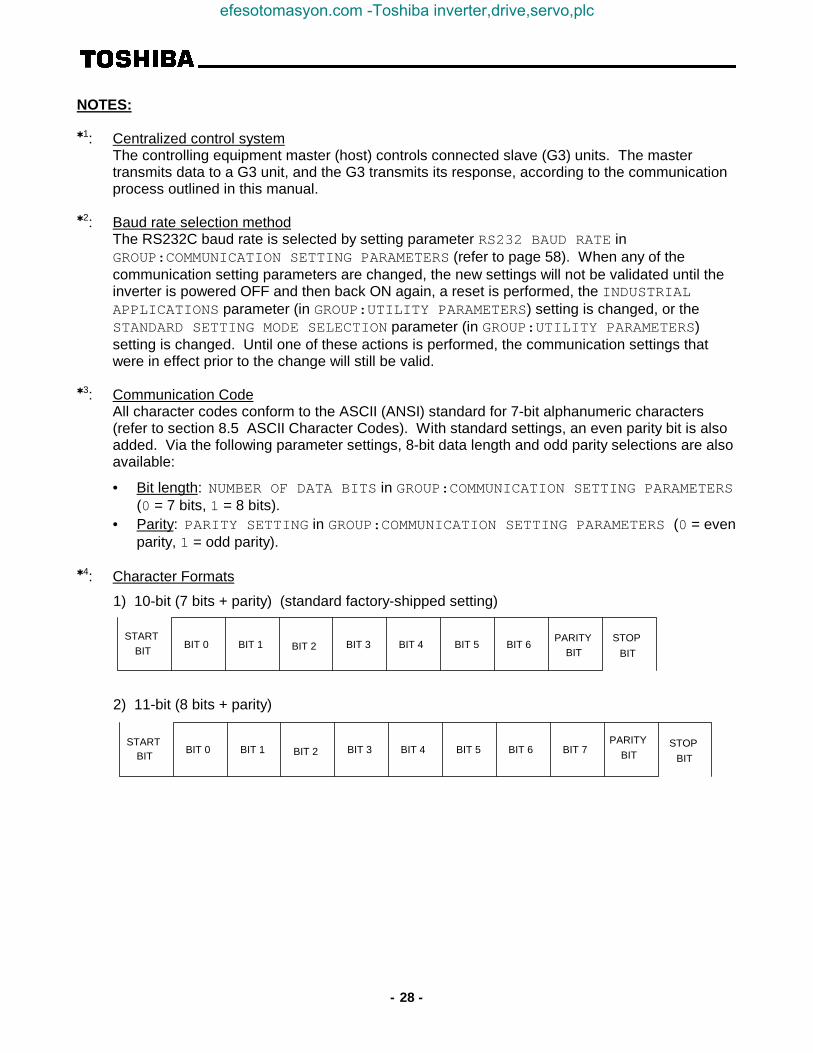
NOTES:
✱1: Centralized control systemThe controlling equipment master (host) controls connected slave (G3) units. The mastertransmits data to a G3 unit, and the G3 transmits its response, according to the communicationprocess outlined in this manual.
✱2: Baud rate selection methodThe RS232C baud rate is selected by setting parameter RS232 BAUD RATE inGROUP:COMMUNICATION SETTING PARAMETERS (refer to page 58). When any of thecommunication setting parameters are changed, the new settings will not be validated until theinverter is powered OFF and then back ON again, a reset is performed, the INDUSTRIALAPPLICATIONS parameter (in GROUP:UTILITY PARAMETERS) setting is changed, or theSTANDARD SETTING MODE SELECTION parameter (in GROUP:UTILITY PARAMETERS)setting is changed. Until one of these actions is performed, the communication settings thatwere in effect prior to the change will still be valid.
✱3: Communication CodeAll character codes conform to the ASCII (ANSI) standard for 7-bit alphanumeric characters(refer to section 8.5 ASCII Character Codes). With standard settings, an even parity bit is alsoadded. Via the following parameter settings, 8-bit data length and odd parity selections are alsoavailable:
• Bit length: NUMBER OF DATA BITS in GROUP:COMMUNICATION SETTING PARAMETERS(0 = 7 bits, 1 = 8 bits).
• Parity: PARITY SETTING in GROUP:COMMUNICATION SETTING PARAMETERS (0 = evenparity, 1 = odd parity).
✱4: Character Formats
1) 10-bit (7 bits + parity) (standard factory-shipped setting)
STARTBIT
BIT 0 BIT 1 BIT 2 BIT 3 BIT 4 BIT 5 BIT 6PARITY
BITSTOP
BIT
2) 11-bit (8 bits + parity)
STARTBIT
BIT 0 BIT 1 BIT 2 BIT 3 BIT 4 BIT 5 BIT 6PARITY
BITSTOP
BITBIT 7
efesotomasyon.com -Toshiba inverter,drive,servo,plc

- 29 -
8.2 Communication Errors
Error Name Error Description Error CodeCannot execute communication was correct, but cannot execute command
(attempt to write a parameter that cannot be written whileinverter is running ✳1, EEPROM error)
0000
Data error data setting value outside of adjustment range,transmission exceeded 14 characters, character otherthan a <CR> received after the “)”, data exceeded 4characters, data not in the range of “0” ∼ “9” or “A” ∼ “F”,character other than “&”, “)”, <CR>, or “+” (only duringread/write commands) received after data, checksum dataexceeded 2 characters.
0001
Address error address data outside of adjustment range when a “W”command was sent, attempt to write data at a protectedaddress ✳2, bank setting was incorrect when a read/writewas performed
0002
Command error command was incorrect 0003Checksum error checksum was incorrect, character other than “)” or <CR>
received after the checksum data0004/
no response ✳4
Format error communications format was incorrect (parity error, overrunerror, framing error) ✳3
no response
Inverter number error inverter number was incorrect, inverter number was only 1character long
no response
✳1: Parameters that cannot be set while the inverter is running are MAXIMUM OUTPUT FREQUENCY,BASE FREQUENCY VOLTAGE SELECT, VOLTS PER HERTZ PATTERN, STANDARD SETTINGMODE SELECTION, and INDUSTRIAL APPLICATIONS .
✳2: The following RAM and EEPROM locations cannot be written to:04D8H ∼ 04F7H, 0500H ∼ 0507H (RAM only), 04FAH bits 4 and 5, 04FBH bit 7, 050AH bits 4 and5 (RAM only), 050BH bit 7 (RAM only), 0512H bits 4 and 5 (RAM only), 0513H bit 7 (RAM only).
✳3: Parity error:....... parity incorrectOverrun error:... new data received before previous data could be read from bufferFraming error:... stop bit position incorrect
✳4: If an inverter number was sent in the transmission and a checksum error occurs, no response willbe sent.
efesotomasyon.com -Toshiba inverter,drive,servo,plc

- 30 -
Communication Error Priority Rankings
1. Format error2. Inverter number error3. Checksum error4. Command error
5. Data error (incorrect data: data characters other than “0” ∼ “9”, “A” ∼ “F”, data length exceeds 4characters, character other than “+” (only during a R/W command), “&”, “)”, or <CR> after the data,or character other than <CR> after the “)” character)
6. Address error (only R/W commands)7. Cannot execute error (only “W” command)8. Data error (data outside of setting limits during “W” command, attempt to write to a protected
location, or bank data outside of limits during “B” command)
Response Data Matrix
Interface RS232CInverter number Yes No
Normal communications ❍ ❍
Cannot execute error ❍ ❍
When Data error ❍ ❍
an Address error ❍ ❍
error Command error ❍ ❍
occurs Checksum error × ❍
Format error × ❏
Inverter number error × ×
❍ ....... Response transmitted.×......... Response not transmitted.❏ ........ Response transmitted when the “(“ character is correctly received. When the “(“ character is
not correctly received, the data is discarded and therefore no response is transmitted.
efesotomasyon.com -Toshiba inverter,drive,servo,plc

- 31 -
8.3 Memory Configuration
RAM: Contains parameter settings and other data that the inverter uses for system control(parameters, commands, status, etc.) When the inverter is powered-off, this data is erased.When the inverter is powered-on, parameter data is copied from EEPROM to RAM (directly inthe case of User Param. #1). Other data is initialized.
EEPROM: Contains user-set parameters and other data. This data is retained even when the inverter ispowered-off.
Internal ROM: Contains control programming and internal ROM version information.
External ROM: Contains control programming and external ROM version information.
Option Bus: Allows access to data contained in installed options.
RAM EEPROM Internal ROM External / Option ROM
1FFFH
059FH
077FH
0517H
04FFH
04F7H
04D8H
03C0H
0100H
0000H
FFFFH
7FFFH
8000H
[Bank = 4][Bank = 0] [Bank = 1] [Bank = 2] [Bank = 3]
OptionData
Option Bus
Program& Data
Program& Data
SystemArea
UserParam. #2
(patternrun)
UserParam. #1
UserParam. #1
SystemParam.
SystemArea
SystemArea
Comm.Command
Area
UserParam. #1
SystemParam.
UserParam. #1
SystemArea
efesotomasyon.com -Toshiba inverter,drive,servo,plc

- 32 -
<< Note >> Shaded areas cannot be written to (read-only). Also, do not attempt to access those areascrossed out with an “X”.
efesotomasyon.com -Toshiba inverter,drive,servo,plc

- 33 -
8.4 Communications Data Tables
• Symbol Definitions(#): Depends on inverter rating.(✳): Cannot be set while inverter is running (attempting to write data while the inverter is running will
result in an error (N0000)).(Note ): Use caution! Because there is no data checking performed on these settings, caution must be used
to not write incorrect data (the “Mask” and “Adjustment Range” sections will be shaded).
• Usage Precautions1: Refer to the inverter instruction manual in conjunction with this manual.2: If the mask data is not correctly set when data is written, the data check function cannot correctly
check the data setting.3: All data is written in hexadecimal (base 16) format (except for “Multiplier” and “Adjustment Range”
data, which is written in decimal (base 10) format).
Parameter Table Usage Method Example
GROUP:FUNDAMENTAL PARAMETERS #1Function / Title Bank Address Mask Adjustment Range Multiplier
MAXIMUM OUTPUT FREQUENCY (✴) 0 / 1 03C0 FFFF 0BB8 ∼ 9C40 (30.00 ∼ 400.00) 0.01
BASE FREQUENCY #1 0 / 1 0428 FFFF 09C4 ∼ 9C40 (25.00 ∼ 400.00) 0.01
HOST COMPUTER → INV. INV. → HOST COMPUTER
(B0) (B0000) ..............Bank(A3C0) (A03C0) ..............Address(MFFFF) (MFFFF) ..............Mask(W1770) (W1770) ..............Data (within adjustment range)
(Since the mask is automatically set to FFFFH whenever the address is set, setting it as shown here is optional.)
• Panel display range (base 10)The actual value displayed on the LCD panel will depend on the setting of FREQUENCY DISPLAYRESOLUTION in GROUP:UTILITY PARAMETERS. When 0.01Hz resolution is selected and theabove example is performed, 60.00Hz will be displayed on the panel. When 0.1Hz resolution isselected, 60.0Hz will be displayed. The “Adjustment Range” column shows a maximum of 5digits, but because the panel can only display 4 digits, the displayed value will be a roundedrepresentation of the actual data setting value.(Ex: If 399.95 (9C3BH) is written to MAXIMUM OUTPUT FREQUENCY (upper limit=400.00),
400.0Hz will be displayed.)
• Display Data / Internal Data Conversion MethodInternal data = [display data ÷ Multiplier], converted to hexadecimal.(Ex: To convert a MAXIMUM OUTPUT FREQUENCY setting of 60Hz to internal data: 60 ÷ 0.01 = 6000,
converted to hexadecimal → 1770H).
Data checks are not performed on parameters that appear in the following datatables with shaded “Mask” and “Adjustment Range” sections. Use extreme caution when setting theseparameters, therefore, as incorrect mask or data settings may cause unpredictable operation.
◊ In this example, the MAXIMUM OUTPUTFREQUENCY setting of the inverter will bechanged from 80Hz to 60Hz.
• Shaded Parameters:
efesotomasyon.com -Toshiba inverter,drive,servo,plc

- 34 -
RS232C Command / Frequency
<< RS232C commands/frequency command will only be valid when the following parameter is respectively configured forRS232C command, frequency, or both. >>
Group Function Bank Address Mask Adjustment Range Multiplier Initialized Value
RS232C Command • frequencymode selection
0 0515 0003 0000: FREQUENCY MODESELECTION, COMMANDMODE SELECTIONsettings
0001: RS232C commands valid0002: RS232C frequency valid0003: RS232C commands and
frequency valid
0000
Group Function Bank Address Mask Adjustment Range Multiplier Initialized Value
RS232C Frequency command 0 0510 FFFF LL ∼ UL (Note 1 ) 0.01 0000
Group Function Bank Address Mask Adjustment Range Multiplier Initialized Value
RS232CCommand
Run • stop commandselection
0 0512 0001 0000: Stop command0001: Run command
0000
Forward • reverse runselection
0 0512 0004 0000: Reverse0004: Forward
0004
Acc/dec #1 / #2selection
0 0512 0008 0000: Acc / dec #10008: Acc / dec #2
0000
Jog mode selection 0 0512 0080 0000: Normal (acc/dec mode)0080: Jog mode
0000
Feedback control(Note 2)
0 0513 0001 0000: Feedback valid0001: Feedback invalid
0000
Compulsory DCinjection braking mode
0 0513 0002 0000: No compulsory DCinjection braking
0002: Compulsory DCinjection below DC INJECTION START FREQUENCY
0000
Fundamentalparameter switching
0 0513 0004 0000: V/F #10004: V/F #2
0000
Gate block command(coast stop command)
0 0513 0008 0000: Normal0008: Gate block
0000
Emergency offcommand
0 0513 0010 0000: Does nothing0010: Emergency off
0000
Reset command(trip clear)
0 0513 0020 0000: Does nothing0020: Reset
0000
Preset speed runcommand
0 0514 000F 0000: Output frequencyselected by FREQUENCYMODE SELECTION
0001 ∼ 000F: speeds 1 ∼ 15
1 0000
Group Function Bank Address Mask Adjustment Range Multiplier Initialized Value
RS232C RS232Ccommunications timer
0 / 1 0445 00FF 0000: Timer OFF0001 ∼ 0064: 1s ∼ 100s
1 EEPROMcontents
(Note 1 ) Throughout the remainder of this document, the abbreviations “LL”, “UL”, and “Fmax” will stand for LOWERLIMIT FREQUENCY, UPPER LIMIT FREQUENCY, and MAXIMUM OUTPUT FREQUENCY, respectively.
(Note 2 ) This parameter only selects whether or not feedback control is valid when feedback control is selected. In orderto use feedback control, parameter FEEDBACK CONTROL SELECTION in GROUP:FEEDBACK CONTROLPARAMETERS must still be set.
efesotomasyon.com -Toshiba inverter,drive,servo,plc

- 35 -
Option Command / Frequency (Valid Only When Option Board Is Installed)
<< The following function is valid only when FREQUENCY MODE SELECTION in GROUP:UTILITYPARAMETERS is set to 3 (communication/12-bit binary option input valid). >>
Group Function Bank Address Mask Adjustment Range Multiplier Initialized Value
Option Frequency command 0 0508 FFFF LL ∼ UL 0.01 0000
<< The following functions are valid only when COMMAND MODE SELECTION in GROUP:UTILITYPARAMETERS is set to 3 (communication option input valid). >>
Group Function Bank Address Mask Adjustment Range Multiplier Initialized Value
OptionCommand
Run • stop commandselection
0 050A 0001 0000: Stop command0001: Run command
0000
Forward • reverse runselection
0 050A 0004 0000: Reverse0004: Forward
0004(Note 1)
Acc/dec #1 / #2selection
0 050A 0008 0000: Acc / dec #10008: Acc / dec #2
0000
Jog mode selection 0 050A 0080 0000: Normal (acc/dec mode)0080: Jog mode
0000
Feedback control(Note 2)
0 050B 0001 0000: Feedback valid0001: Feedback invalid
0000
Compulsory DCinjection braking mode
0 050B 0002 0000: No compulsory DCinjection braking
0002: Compulsory DCinjection below DC INJECTION START FREQUENCY
0000
Fundamentalparameter switching
0 050B 0004 0000: V/F #10004: V/F #2
0000
Gate block command(coast stop command)
0 050B 0008 0000: Normal0008: Gate block
0000
Emergency offcommand
0 050B 0010 0000: Does nothing0010: Emergency off
0000
Reset command(trip clear)
0 050B 0020 0000: Does nothing0020: Reset
0000
Preset speed runcommand
0 050C 000F 0000: Output frequencyselected by FREQUENCYMODE SELECTION
0001 ∼ 000F: speeds 1 ∼ 15
1 0000
Group Function Bank Address Mask Adjustment Range Multiplier Initialized Value
RS485 RS485communications timer
0 / 1 04CC 00FF 0000: Timer OFF
0001 ∼ 0064: 1s ∼ 100s
1 EEPROMcontents
(Note 1 ) The initialized value is 0004 only when an option ROM is installed and a communications option (RS485,TOSLINE-F10, TOSLINE-S20, DeviceNet or RIO) is selected (COMMUNICATION SELECTION inGROUP:COMMUNICATION SETTING PARAMETERS = 1 ∼ 3). Otherwise, it is initialized to 0000.
(Note 2 ) This parameter only selects whether or not feedback control is valid when feedback control is selected. In orderto use feedback control, parameter FEEDBACK CONTROL SELECTION in GROUP:FEEDBACK CONTROLPARAMETERS must still be set.
efesotomasyon.com -Toshiba inverter,drive,servo,plc

- 36 -
Panel Command / Frequency
<< The following function is valid only when FREQUENCY MODE SELECTION in GROUP:UTILITYPARAMETERS is set to 2 (panel input valid) or 4 (local/remote changeover possible). >>
Group Function / Title Bank Address Mask Adjustment Range Multiplier
Panel FREQUENCY COMMAND 0 04F8 FFFF LL ∼ UL 0.01
<< The following functions are valid only when COMMAND MODE SELECTION in GROUP:UTILITYPARAMETERS is set to 2 (panel input valid) or 4 (local/remote changeover possible). >>
Group Function / Title Bank Address Mask Adjustment Range Multiplier
PanelCommand
Run • stop command selection 0(Note 1)
04FA 0001 0000: Stop command0001: Run command
DIRECTION SELECTION (FORWARD/REV) 0 / 1 04FA 0004 0000: Reverse0004: Forward
ACCEL/DECEL #1/#2 SELECTION 0 / 1 04FA 0008 0000: Acc / dec #10008: Acc / dec #2
Jog mode selection 0(Note 1)
04FA 0080 0000: Normal (acc/dec mode)0080: Jog mode
PANEL FEEDBACK CONTROL (Note 2) 0 / 1 04FB 0001 0000: Feedback valid0001: Feedback invalid
Compulsory DC injection braking mode 0(Note 1)
04FB 0002 0000: No compulsory DCinjection braking
0002: Compulsory DC injectionbelow DC INJECTIONSTART FREQUENCY
FUNDAMENTAL PARAM SWITCHING 0 / 1 04FB 0004 0000: V/F #10004: V/F #2
Gate block command 0(Note 1)
04FB 0008 0000: Normal0008: Gate block
Emergency off command 0(Note 1)
04FB 0010 0000: Does nothing0010: Emergency off
Reset command 0(Note 1)
04FB 0020 After writing 0020 (“TRIPCLEAR COMMAND (PRESSCLEAR)“) will be displayed),write 0000 and the inverter willreset
Preset speed run command 0(Note 1)
04FC 000F 0000: Output frequencyselected by FREQUENCYMODE SELECTION
0001 ∼ 000F: speeds 1 ∼ 15
1
(Note 1 ) It is also possible to write to bank 1 (EEPROM), but this is not for normal command use. To avoid the possibilityof unpredictable operation, do not write these commands to bank 1.
(Note 2 ) This parameter only selects whether or not feedback control is valid when feedback control is selected. In orderto use feedback control, parameter FEEDBACK CONTROL SELECTION in GROUP:FEEDBACK CONTROLPARAMETERS must still be set.
efesotomasyon.com -Toshiba inverter,drive,servo,plc

- 37 -
Inverter Status Monitor (Read Only)
Function Bank Address Mask DataLength
Contents (Units) Multiplier
Operating frequency monitor 0 0524 FFFF word Hz 0.01Rotation direction monitor 0 05B6 0004 bit → inverter status monitor 1 Frequency command monitor 0 0500 FFFF word Hz 0.01Output current monitor 0 0576 00FF byte % 1Input voltage monitor (Note 1) 0 05B2 FFFF word % 0.1Output voltage monitor (Note 1) 0 05B0 FFFF word % 0.1Input terminal status monitor 0 057A FFFF word → bit monitor 1 Output terminal status monitor 0 0579 00FF byte → bit monitor 2 Cumulative run time (Note 2) 0 05A6 FFFF word 1
05D2 0008 bit 1
Past trips (Note 3)(4 most recent trips)
0 / 1 04F3∼ 04F7
007F 5 bytes → Table 1, Table 2
Pre-compensation frequency 0 0524 FFFF word Hz 0.01Post-compensation frequency 0 0260 FFFF word Hz 0.01Torque current monitor 0 0684 FFFF word % (Note 4 ) 0.01Excitation current monitor 0 0688 00FF byte % 1PID feedback value 0 0506 FFFF word Hz (Note 4 ) 0.02Motor overload ratio 0 0584 FFFF word % (Note 5 )Inverter overload ratio 0 0586 FFFF word % (Note 5 )DBR overload ratio 0 0588 FFFF word % (Note 5 )Input / output power units 0 03AE 0008 bit 0000: 0.01kW
0008: 0.1kW(Note 6)
Input power (%) (Note 7) 0 035C FFFF word % 0.1Input power (kW) 0 0350 FFFF word kW (Note 6)Output power (%) (Note 7) 0 035E FFFF word % (Note 4 ) 0.1Output power (kW) 0 0352 FFFF word kW (Note 4) (Note 6)RR input 0 0550 FFFF word % (Note 5 )Present trip 0 0591 007F byte → Table 1 Command mode status 0 05B8 0003 2 bits 00: terminal
01: panel02: option03: RS232C
Frequency mode selection status 0 05B8 000C 2 bits 00: terminal04: panel08: option0C: RS232C
CPU version number 2 8000 FFFF word 1
External ROM version number 3 0000 FFFF word 1
EEPROM version number 1 0380 FFFF word 1
Inverter typeform monitor 0 05CA 00FF byte → Table 5 1
(Note 1) These monitor voltage units are not affected by the setting of VOLTAGE UNITS SELECTION in GROUP:UTILITY PARAMETERS -they are always in %.
(Note 2) The time range for the cumulative run timer is 0000H ∼ FFFFH (0 ∼ 65535 hours), counted at address 05A6 in bank 0. When thetimer reaches a count of 65536, bit 3 of address 05D2 in bank 0 is set, and the count at address 05A6 is cleared. At a count of65537, therefore, address 05A6 will contain 0001H and bit 3 of address 05D2 will be set.
Cumulative run time monitor example:HOST COMPUTER → INVERTER INVERTER → HOST COMPUTER
(A5D2) (A05D2) .................. select rollover bit address(M0008) (M0008) .................. mask off rollover bit(R) (R0008) .................. timer has rolled-over ( ≥ 65536 hours)(A5A6) (A05A6) .................. select timer address(R) (R000A) .................. timer = 10 (total time = 65546 hours)
efesotomasyon.com -Toshiba inverter,drive,servo,plc

- 38 -
(Note 3) Past trips are stored in a ring-buffer format, with the most recent trip located at the address following the 00H starting point.
(Note 4) Uses signed data (data values larger than 7FFFH are negative). If internal data is 8000H or larger, the actual value can beobtained by: actual value = - [FFFF H - (internal data) + 1] .
(Note 5 ) Multiplier is 100/65535.
(Note 6) If the input / output power units data is 0000, the monitored data is in 0.01kW units, and the multiplier is 0.01. If the input / outputpower units data is 0008, the monitored data is in 0.1kW units, and the multiplier is 0.1. These values are automatically setaccording to the inverter typeform.
(Note 7) 100% = √3 × rated voltage × rated current (with some variation for losses).
Input Terminal Status MonitorBit Monitor 1Lower Byte
057AH Input Terminal 0 1 Single-BitRead Mask
bit 0 F terminal - CC open terminal - CC shorted 0001bit 1 R terminal - CC open terminal - CC shorted 0002bit 2 S1 terminal - CC open terminal - CC shorted 0004bit 3 S2 terminal - CC open terminal - CC shorted 0008bit 4 S3 terminal - CC open terminal - CC shorted 0010bit 5 S4 terminal - CC open terminal - CC shorted 0020bit 6 S5 (option) terminal - CC open terminal - CC shorted 0040bit 7 S6 (option) terminal - CC open terminal - CC shorted 0080
Bit Monitor 1Upper Byte
057BH Input Terminal 0 1 Single-BitRead Mask
bit 0 unused (always 0) bit 1 unused (always 0) bit 2 unused (always 0) bit 3 unused (always 0) bit 4 unused (always 0) bit 5 S7 (option) terminal - CC open terminal - CC shorted 0020bit 6 RES terminal - CC open terminal - CC shorted 0040bit 7 ST terminal - CC open terminal - CC shorted 0080
Ex. 1) Input terminal monitor example:
HOST COMPUTER → INVERTER INVERTER → HOST COMPUTER(A57A) (A057A)(R) (R8025)
1000 0000 0010 0101
In this example, terminals ST, S4, S1 and F are shorted to CC, and all others are open.
Ex. 2) Example of monitoring only terminals S1 ∼ S4:
HOST COMPUTER → INVERTER INVERTER → HOST COMPUTER(A57A) (A057A)(M003C) (M003C)(R) (R0004)
In this example, terminal S1 is shorted to CC, and S2 ∼ S4 are open.
efesotomasyon.com -Toshiba inverter,drive,servo,plc

- 39 -
Output Terminal Status MonitorBit Monitor 2 0579H Output Terminal 0 1 Single-Bit
Read Maskbit 0 unused (always 0) bit 1 unused (always 0) bit 2 FAN OFF ON 0004bit 3 FL FLB-FLC shorted FLA-FLC shorted 0008bit 4 MS relay OFF ON 0010bit 5 OUT (option) OUTB-OUTC shorted OUTA-OUTC shorted 0020bit 6 RCH RCHA-RCHC open RCHA-RCHC shorted 0040bit 7 LOW LOWA-LOWC open LOWA-LOWC shorted 0080
Inverter Status MonitorInverterStatus 1
05B6H Inverter Status 0 1 Single-BitRead Mask
Lower Byte bit 0 running (acc/dec) running 0001
bit 1 unused (always 0) bit 2 forward / reverse reverse forward 0004bit 3 acc/dec #1/#2 acc/dec #1 acc/dec #2 0008bit 4 for inverter use bit 5 for inverter use bit 6 for inverter use bit 7 jog/normal mode normal (acc/dec) jog mode 0080
InverterStatus 1
05B7H Inverter Status 0 1 Single-BitRead Mask
Upper Byte bit 0 feedback ON/OFF OFF feedback active 0001bit 1 DC inject. braking OFF DC inject. braking active 0002bit 2 V/F #1/#2 V/F #1 V/F #2 0004bit 3 coasting not coasting coasting 0008bit 4 emergency off not in emergency off in emergency off 0010bit 5 for inverter use bit 6 for inverter use bit 7 for inverter use
InverterStatus 2
05BBH Inverter Status 0 1 Single-BitRead Mask
bit 0 accelerating not accelerating accelerating 0001bit 1 decelerating not decelerating decelerating 0002bit 2 for inverter use bit 3 retry not retrying retrying 0008bit 4 running (including
DC inject. braking)stopped running 0010
bit 5 for inverter use bit 6 for inverter use bit 7 tripped not tripped tripped 0080
Ex) Inverter status monitoring example (reading the status of inverter number “00”):
HOST COMPUTER → INVERTER INVERTER → HOST COMPUTER(00A5B6) (00A05B6)(00R) (00R000D)
0000 0000 0000 1101
In this example, the inverter is running forward in normal acc/dec mode using acc/dec #2 and V/F #1.
efesotomasyon.com -Toshiba inverter,drive,servo,plc

- 40 -
Table 1. List of trips (trips registered as past faults)
LCD Display Message Data (Hex) ExplanationNO ERROR ××00 No error has been recorded since the last inverter
reset or trip clearOVERCURRENT (ACCEL)
(PRESS CLEAR)××01 Overcurrent during acceleration
OVERCURRENT (DECEL)(PRESS CLEAR)
××02 Overcurrent during deceleration
OVERCURRENT (RUN)(PRESS CLEAR)
××03 Overcurrent during constant-speed run
LOAD-END OVERCURRENT(PRESS CLEAR)
××04 Load-end overcurrent detected at start-up (outputterminals, motor wiring etc.)
U-PHASE SHORT CKT(PRESS CLEAR)
××05 U-phase armature short circuit
V-PHASE SHORT CKT(PRESS CLEAR)
××06 V-phase armature short circuit
W-PHASE SHORT CKT(PRESS CLEAR)
××07 W-phase armature short circuit
LOST INPUT PHASE(PRESS CLEAR)
××08 Lost input phase (option)
LOST OUTPUT PHASE(PRESS CLEAR)
××09 Lost output phase (option)
OVERVOLTAGE (ACCEL)(PRESS CLEAR)
××0A Overvoltage during acceleration
OVERVOLTAGE (DECEL)(PRESS CLEAR)
××0B Overvoltage during deceleration
OVERVOLTAGE (RUN)(PRESS CLEAR)
××0C Overvoltage during constant-speed run
INVERTER OVERLOAD(PRESS CLEAR)
××0D Inverter overload
MOTOR OVERLOAD(PRESS CLEAR)
××0E Motor overload
DBR OVERLOAD TRIP(PRESS CLEAR)
××0F Dynamic braking resistor overload
OVERHEAT TRIP(PRESS CLEAR)
××10 Inverter overheat
EMERGENCY OFF(PRESS CLEAR)
××11 Emergency off
EEPROM WRITE FAILURE(PRESS CLEAR)
××12 EEPROM failure during write
EEPROM READ FAILURE(PRESS CLEAR)
××13 EEPROM failure during initial read
××14 UnusedRAM ERROR
(PRESS CLEAR)××15 RAM error
ROM ERROR(PRESS CLEAR)
××16 ROM error
CPU ERROR(PRESS CLEAR)
××17 CPU error
efesotomasyon.com -Toshiba inverter,drive,servo,plc

- 41 -
LCD Display Message Data (Hex) ExplanationCOMMUNICATION ERROR
(PRESS CLEAR)××18 RS232C timer time-out
GATE ARRAY FAULT(PRESS CLEAR)
××19 Gate array error
CURRENT DETECT ERROR(PRESS CLEAR)
××1A Output current detection circuit error
OPTION PCB ERROR(PRESS CLEAR)
××1B Option PCB error
OPTION ROM ERROR ××1C Option ROM errorLOW CURRENT TRIP
(PRESS CLEAR)××1D Low current
UNDERVOLTAGE TRIP(PRESS CLEAR)
××1E Main circuit undervoltage
××1F UnusedOVERTORQUE TRIP
(PRESS CLEAR)××20 Overtorque
EARTH FAULT (SOFT)(PRESS CLEAR)
××21 Earth fault (software)
EARTH FAULT (HARD)(PRESS CLEAR)
××22 Earth fault (hardware)
OPEN FUSE TRIP(PRESS CLEAR)
××23 Open fuse
DBR OVERCURRENT TRIP(PRESS CLEAR)
××24 Dynamic braking resistor overcurrent
DC OVERCURRENT (ACC)(PRESS CLEAR)
××25 Overcurrent in DC section during acceleration
DC OVERCURRENT (DEC)(PRESS CLEAR)
××26 Overcurrent in DC section during deceleration
DC OVERCURRENT (RUN)(PRESS CLEAR)
××27 Overcurrent in DC section during constant-speed run
AUTO-TUNING ERROR(PRESS CLEAR)
××28 Auto-tuning error
INV TYPEFORM ERROR(PRESS READ/WRITE)
××29 Inverter typeform error
efesotomasyon.com -Toshiba inverter,drive,servo,plc

- 42 -
Table 2. Trip data configuration ( : starting point)
When a trip occurs, the oldest trip becomes the starting point (00H), and the most recent trip is placed atthe previous starting point address (refer to Table 1 for trip codes):
04F3H 04F4H 04F5H 04F6H 04F7H Trip Status
00H 00H 00H 00H 00H Initial status (no trips)00H 00H 00H 00H 01H 1st trip00H 01H 03H 0BH 01H 4th trip0BH 01H 03H 0BH 00H 5th trip0BH 01H 03H 00H 13H 6th trip
Table 3. Pre-alarm status monitor data (bank 0)
05D4H Function LCD Display Message 0 1
bit 0 ∼ bit 3 unused bit 4 overload pre-alarm status OVERLOAD no pre-alarm pre-alarmbit 5 overvoltage pre-alarm status OVERVOLTAGE no pre-alarm pre-alarmbit 6 overcurrent pre-alarm status OVERCURRENT no pre-alarm pre-alarmbit 7 overheat pre-alarm status OVERHEAT no pre-alarm pre-alarm
Table 4. Messages (non-trips)
LCD Display Message Bank Address Mask DataINVERTER OFF
(ST-CC IS OPEN)0 051B 0008 0008: ST-CC open
CONTROL POWER LOW 0 05B4 0010 0010: control circuit undervoltage
DC BUSUNDERVOLTAGE
0 05B4 0001 0001: main circuit undervoltage
FREQUENCY POINTSETTING ERROR
0 05D4 0002 0002: frequency point setting error alarm
Message monitor example :
HOST COMPUTER → INVERTER INVERTER → HOST COMPUTER(B0) (B0000)(A5B4) (A05B4)(M0001) (M0001)(R) (R0001)
In this case, a main circuit undervoltage condition is being indicated.
efesotomasyon.com -Toshiba inverter,drive,servo,plc

- 43 -
Table 5. Inverter typeform codes
230v Class 460v Class 575v Class
InverterModel
TypeformData (Hex)
InverterModel
TypeformData (Hex)
InverterModel
TypeformData (Hex)
G3-2010 ××21 G3-4015 ××42 G3-6060 ××65G3-2015 ××22 G3-4025 ××43 G3-6120 ××67G3-2025 ××23 G3-4035 ××44 G3-6160 ××68G3-2035 ××24 G3-4055 ××45 G3-6220 ××69G3-2055 ××25 G3-4080 ××46 G3-6270 ××6AG3-2080 ××26 G3-4110 ××47 G3-6330 ××6BG3-2110 ××27 G3-4160 ××48 G3-6400 ××6CG3-2160 ××28 G3-4220 ××49 G3-6500 ××6DG3-2220 ××29 G3-4270 ××4A G3-6600 ××6EG3-2270 ××2A G3-4330 ××4B G3-6750 ××6FG3-2330 ××2B G3-4400 ××4C G3-610K ××70G3-2400 ××2C G3-4500 ××4D G3-612K ××71
G3-4600 ××4E G3-615K ××72G3-4750 ××4F G3-620K ××73G3-410K ××50G3-412K ××51G3-415K ××52G3-420K ××53G3-425K ××54G3-430K ××55
efesotomasyon.com -Toshiba inverter,drive,servo,plc

- 44 -
Parameter List
GROUP:FUNDAMENTAL PARAMETERS #1Function / Title Bank Address Mask Adjustment Range Multiplier
MAXIMUM OUTPUT FREQUENCY (✴) 0 / 1 03C0 FFFF 0BB8 ∼ 9C40 (30.00 ∼ 400.00) 0.01
BASE FREQUENCY #1 0 / 1 0428 FFFF 09C4 ∼ 9C40 (25.00 ∼ 400.00) 0.01
BASE FREQUENCY VOLTAGE SELECT (Note , ✴) 0 / 1 04BE 0030 0000: Input voltage level (0)0020: Automatic setting (1)0030: Stationary setting (2)
MAXIMUM OUTPUT VOLTAGE #1 0 / 1 0426 FFFF 0000 ∼ 0258 (0 ∼ 600) 1
REVERSE OPERATION DISABLE SELECT 0 / 1 04B6 0020 0000: Reverse allowed (0)0020: Reverse not allowed (1)
UPPER LIMIT FREQUENCY 0 / 1 03C2 FFFF 0 ∼ Fmax 0.01LOWER LIMIT FREQUENCY 0 / 1 03C4 FFFF 0 ∼ UL, Fmax
VOLTS PER HERTZ PATTERN (Note , ✴) 0 / 1 042D 000F 0000: Constant torque (1)0001: Variable torque (2)0002: Auto. torque boost (3)0006: 3 w/ auto. eng. sav. (4)000A: vector control (5)000E: 5 w/ auto. eng. sav. (6)
1 • 2 VOLTAGE BOOST #1 0 / 1 0424 FFFF 0000 ∼ 012C (0.0 ∼ 30.0) 0.1
ACCELERATION TIME #1 (Ref. 1) 0 / 1 03C6 FFFF 0001 ∼ EA60 0.01 / 0.1DECELERATION TIME #1 0 / 1 03C8 FFFF (0.01 ∼ 600.00 / 0.1 ∼ 6000.0)ACC/DEC PATTERN #1 SELECTION 0 / 1 042D 0030 0000: Linear (0)
0010: Self-adjusting (1)0020: S-Pattern #1 (2)0030: S-Pattern #2 (3)
ACCEL/DECEL PATTERN ADJUST LOW 0 / 1 04C4 00FF 0003 ∼ 00FD (0 ∼ 50) (Special )ACCEL/DECEL PATTERN ADJUST HIGH 0 / 1 04C5 00FF
Codes used throughout this parameter list:
(✴) : Cannot set while inverter is running.
(Note ) : No data checking performed → “Mask” and “Adjustment Range” sections will be shaded.
(Special ) : Internal data = (display setting × 5 + 3), converted to hexadecimal.
(Ref. 1) : The adjustment range and multiplier depend on the setting of ACC/DEC TIME UNITSSELECTION in GROUP:UTILITY PARAMETERS as follows:
When ACC/DEC TIME UNITS SELECTION is set for 0.1 sec. units, adjustment range =0.1 ∼ 6000.0, and multiplier = 0.1.When ACC/DEC TIME UNITS SELECTION is set for 0.01 sec. units, adjustment range= 0.01 ∼ 600.00, and multiplier = 0.01.
In addition, if the setting of ACC/DEC TIME UNITS SELECTION is changed after settingthe ACC/DEC times, the ACC/DEC times will become 10 times or 0.1 times their formervalue. Therefore, always reset the ACC/DEC time settings after changing the setting ofACC/DEC TIME UNITS SELECTION .
efesotomasyon.com -Toshiba inverter,drive,servo,plc

- 45 -
GROUP:FUNDAMENTAL PARAMETERS #2Function / Title Bank Address Mask Adjustment Range Multiplier
BASE FREQUENCY #2 0 / 1 0432 FFFF 09C4 ∼ 9C40 (25.00 ∼ 400.00) 0.01
MAXIMUM OUTPUT VOLTAGE #2 0 / 1 0430 FFFF 0000 ∼ 0258 (0 ∼ 600) 1
VOLTAGE BOOST #2 0 / 1 042E FFFF 0000 ∼ 012C (0.0 ∼ 30.0) 0.1
ELECTRONIC THERMAL PROTECT LVL #2 0 / 1 0434 00FF 000A ∼ 0064 (10 ∼ 100) 1
STALL PROTECTION SELECTION #2 0 / 1 0437 0040 0000: ON (0)0040: OFF (1)
0 STALL PROTECTION LEVEL #2 0 / 1 0435 00FF 000A ∼ 00D7 (10 ∼ 215) 1
ACCELERATION TIME #2 (Ref. 1) 0 / 1 03CA FFFF 0001 ∼ EA60 0.01 / 0.1DECELERATION TIME #2 0 / 1 03CC FFFF (0.01 ∼ 600.00 / 0.1 ∼ 6000.0)ACC/DEC PATTERN #2 SELECTION 0 / 1 0437 0030 0000: Linear (0)
0010: Self-adjusting (1)0020: S-Pattern #1 (2)0030: S-Pattern #2 (3)
ACC/DEC #1/#2 SWITCH FREQUENCY 0 / 1 0406 FFFF 0000 ∼ Fmax 0.01
<< The following functions are valid only when COMMAND MODE SELECTION in GROUP:UTILITYPARAMETERS is set to 2 (panel input valid) or 4 (local/remote changeover possible). >>
GROUP:PANEL CONTROL PARAMETERSFunction / Title Bank Address Mask Adjustment Range Multiplier
DIRECTION SELECTION (FORWARD/REV) 0 / 1 04FA 0004 0000: Reverse (0)0004: Forward (1)
STOP PATTERN SELECTION 0 / 1 045C 0040 0000: Decelerated stop (0)0040: Coast stop (1)
FUNDAMENTAL PARAM SWITCHING 0 / 1 04FB 0004 0000: V/F #1 (1)0004: V/F #2 (2)
ACCEL/DECEL #1/#2 SELECTION 0 / 1 04FA 0008 0000: Acc / dec #1 (1)0008: Acc / dec #2 (2)
PANEL RESET SELECTION 0 / 1 045C 0030 0000: All possible (0)0010: overload only (1)0020: overload, overcurrent
only (2)
PANEL FEEDBACK CONTROL (Note 1) 0 / 1 04FB 0001 0000: Feedback valid (0)0001: Feedback invalid (1)
(Note 1 ): This parameter only selects whether or not feedback control is valid when feedback controlis selected. In order to use feedback control, parameter FEEDBACK CONTROLSELECTION in GROUP:FEEDBACK CONTROL PARAMETERS must still be set.
efesotomasyon.com -Toshiba inverter,drive,servo,plc

- 46 -
GROUP:TERMINAL SELECTION PARAMETERSFunction / Title Bank Address Mask Adjustment Range Multiplier
INPUT TERMINAL SELECTION 0 / 1 04BB 0001 0000: Standard functions (0)0001: Individual selection (1)
1 “R” INPUT TERMINAL FUNCTION 0 / 1 046C FFFF 0000 ∼ FFFF (0 ∼ 54) “S1” INPUT TERMINAL FUNCTION 0 / 1 046E FFFF“S2” INPUT TERMINAL FUNCTION 0 / 1 0470 FFFF“S3” INPUT TERMINAL FUNCTION 0 / 1 0472 FFFF“S4” INPUT TERMINAL FUNCTION 0 / 1 0474 FFFF Refer to Table 6“F” INPUT TERMINAL FUNCTION 0 / 1 0476 FFFF“RES” INPUT TERMINAL FUNCTION 0 / 1 0478 FFFF (Note)“ST” INPUT TERMINAL FUNCTION 0 / 1 047A FFFF“S5” INPUT TERMINAL FUNCTION 0 / 1 047C FFFF“S6” INPUT TERMINAL FUNCTION 0 / 1 047E FFFF“S7” INPUT TERMINAL FUNCTION 0 / 1 0480 FFFFPOTENTIAL TERMINAL FUNCTION 0 / 1 0482 FFFF
R,S1-S7 TERMINAL RESPONSE TIME 0 / 1 0462 00FF 0001 ∼ 0064 (1 ∼ 100) 1
F INPUT TERMINAL RESPONSE TIME 0 / 1 0463 00FF 0001 ∼ 0064 (1 ∼ 100) 1
RES INPUT TERMINAL RESPONSE TIME 0 / 1 0464 00FF 0001 ∼ 0064 (1 ∼ 100) 1
ST INPUT TERMINAL RESPONSE TIME 0 / 1 0465 00FF 0001 ∼ 0064 (1 ∼ 100) 1
“RCH” CONTACTS FUNCTION 0 / 1 0490 FFFF 0 ∼ FFFF (0 ∼ 63) See Table 7 “RCH” CONTACTS DELAY TIME 0 / 1 0492 00FF 0001 ∼ 0064 (1 ∼ 100)
“RCH” CONTACTS HOLD TIME (Note) 0 / 1 0493 00FF 0001 ∼ 0064 (1 ∼ 100)“LOW” CONTACTS FUNCTION 0 / 1 048C FFFF 0 ∼ FFFF (0 ∼ 63) See Table 7 “LOW” CONTACTS DELAY TIME 0 / 1 048E 00FF 0001 ∼ 0064 (1 ∼ 100)
“LOW” CONTACTS HOLD TIME (Note) 0 / 1 048F 00FF 0001 ∼ 0064 (1 ∼ 100)“FL” CONTACTS FUNCTION 0 / 1 0494 FFFF 0 ∼ FFFF (0 ∼ 63) See Table 7 “FL” CONTACTS DELAY TIME 0 / 1 0496 00FF 0001 ∼ 0064 (1 ∼ 100)
“FL” CONTACTS HOLD TIME (Note) 0 / 1 0497 00FF 0001 ∼ 0064 (1 ∼ 100)“OUT” CONTACTS FUNCTION 0 / 1 0498 FFFF 0 ∼ FFFF (0 ∼ 63) See Table 7 “OUT” CONTACTS DELAY TIME 0 / 1 049A 00FF 0001 ∼ 0064 (1 ∼ 100)
“OUT” CONTACTS HOLD TIME (Note) 0 / 1 049B 00FF 0001 ∼ 0064 (1 ∼ 100)LOW SPEED SIGNAL OUTPUT FREQ 0 / 1 03FE FFFF 0 ∼ Fmax 0.01
ACC/DEC COMPLETE DETECT BAND 0 / 1 0400 FFFF 0 ∼ Fmax 0.01
SPEED REACH MAXIMUM FREQUENCY 0 / 1 0404 FFFF 0 ∼ Fmax 0.01
SPEED REACH MINIMUM FREQUENCY 0 / 1 0402 FFFF 0 ∼ Fmax 0.01
COMMERCIAL POWER/INV SWITCHING OUTPUT 0 / 1 04C1 00C0 0000: OFF (0)0040: Auto. switch on trip (1)0080: Switch at COMMERCIAL
POWER/INV SWITCHFREQ (2)
00C0: Both (1) and (2) (3)
2 • 3 COMMERCIAL POWER/INV SWITCH FREQ 0 / 1 041C FFFF 0 ∼ Fmax 0.01
“FP” OUTPUT TERMINAL PULSE FREQUENCY 0 / 1 04C0 0003 0000: 48f (0)0001: 96f (1)0002: 360f (2)
RR INPUT SPECIAL FUNCTION SELECT (Note) 0 / 1 04B8 00E0 0000: Standard (0)0040: Fmax (1)0080: TACC/TDEC mult. (2)00C0: VB mult. factor (3)0020: CL mult. factor (4)
efesotomasyon.com -Toshiba inverter,drive,servo,plc

- 47 -
Table 6. Input terminal selections
SettingValue
Data(Hex)
Function SettingValue
Data(Hex)
Function
0 10C8 R (reverse run) 28 04AF Binary bit #6
1 011C SS1 (preset speed selection) 29 08AF Binary bit #7
2 021C SS2 (preset speed selection) 30 10AF Binary bit #8
3 041C SS3 (preset speed selection) 31 20AF Binary bit #9
4 081C SS4 (preset speed selection) 32 40AF Binary bit #10
5 20C8 F (forward run) 33 04CE No effect
6 201B RES (fault reset) 34 01C7 UP/DOWN frequency setting(UP)
7 C0C9 ST (gate ON/OFF) 35 02C7 UP/DOWN frequency setting(DOWN)
8 0CC8 JOG selection 36 04C7 UP/DOWN frequency clear
9 081A Acc/dec #1/#2 selection 37 08C7 PUSH-type RUN key
10 101B Emergency off 38 10C7 PUSH-type STOP key
11 021B DC injection brakingON/OFF
39 02B9 No effect
12 041B Fundamental parameterswitching (V/F #2)
40 C0C8 Forward/reverse run selection
13 011B Feedback control ON/OFF 41 20C7 RUN
14 10CE Pattern run selection #1 42 30C9 Binary data write
15 20CE Pattern run selection #2 43 0198 [LOCAL/REMOTE] key
16 40CE Pattern run selection #3 44 0298 [MON] key
17 80CE Pattern run selection #4 45 0498 [PRG] key
18 02CE Pattern run continue signal 46 0898 [UP] (▲) key
19 01CE Pattern run step triggersignal
47 1098 [DOWN] (▼) key
20 0AC9 JOG forward run 48 2098 [READ/WRITE] key
21 06C9 JOG reverse run 49 4098 [RUN] key
22 10AE Binary bit #0 50 8098 [STOP/CLEAR] key
23 20AE Binary bit #1 51 08CE Commercial power / inverterswitching signal
24 40AE Binary bit #2 52 40C7 Reserved for option use
25 80AE Binary bit #3 53 10CB RR frequency switching input
26 01AF Binary bit #4 54 20CB IV frequency switching input
27 02AF Binary bit #5
(Note ): In order for binary bit #0 ∼ #10 (setting values 22 ∼ 32) and UP/DOWN frequency setting (settingvalues 34 & 35) inputs to be valid, parameter FREQUENCY PRIORITY SELECTION #1 orFREQUENCY PRIORITY SELECTION #2 in GROUP:FREQUENCY SETTING PARAMETERS must beset to 5 (BIN (binary setting or UP/DOWN setting)).
efesotomasyon.com -Toshiba inverter,drive,servo,plc

- 48 -
Table 7. Output terminal selections (RCH, LOW, FL, OUT relay contacts)
SettingValue
Data(Hex)
Function SettingValue
Data(Hex)
Function
0 0000 Lower limit frequency 32 C5B7 Executing emergency off
1 0100 /Lower limit frequency 33 CDB7 /Executing emergency off
2 0200 Upper limit frequency 34 B5BB Executing retry
3 0300 /Upper limit frequency 35 BDBB /Executing retry
4 0400 Low speed signal 36 D5CF Pattern run switching output
5 0500 /Low speed signal 37 DDCF /Pattern run switching output
6 0600 Accel/decel complete 38 D5D8 PID deviation limit
7 0700 /Accel/decel complete 39 DDD8 /PID deviation limit
8 0800 Selected speed reach signal 40 C5BB Run/stop
9 0900 /Selected speed reach signal 41 CDBB /Run/stop
10 0A00 Fault 42 1400 Severe fault (armature short,load-end short, open phase,output error, earth fault)
11 0B00 /Fault 43 1500 /Severe fault (armature short,load-end short, open phase,output error, earth fault)
12 0C00 Fault other than earth fault orload-end overcurrent
44 1600 Non-severe fault (overload,overcurrent, overvoltage)
13 0D00 /Fault other than earth fault orload-end overcurrent
45 1700 /Non-severe fault (overload,overcurrent, overvoltage)
14 95B5 Overcurrent pre-alarm 46 E5D8 Commercial power / inverterswitching output #1
15 9DB5 /Overcurrent pre-alarm 47 EDD8 /Commercial power / inverterswitching output #1
16 85C5 Inverter overload pre-alarm 48 F5D8 Commercial power / inverterswitching output #2
17 8DC5 /Inverter overload pre-alarm 49 FDD8 /Commercial power / inverterswitching output #2
18 95C5 Motor overload pre-alarm 50 85C0 Fan ON/OFF
19 9DC5 /Motor overload pre-alarm 51 8DC0 /Fan ON/OFF
20 D5C5 Overheat pre-alarm 52 F5B6 Executing JOG
21 DDC5 /Overheat pre-alarm 53 FDB6 /Executing JOG
22 A5B4 Overvoltage pre-alarm 54 1800 Local/remote operation
23 ADB4 /Overvoltage pre-alarm 55 1900 /Local/remote operation
24 E5B4 Undervoltage alarm 56 A5D1 Cumulative timer alarm
25 EDB4 /Undervoltage alarm 57 ADD1 /Cumulative timer alarm
26 85B5 Undercurrent alarm 58 1A00 Communication error alarm
27 8DB5 /Undercurrent alarm 59 1B00 /Communication error alarm
28 85D1 Overtorque alarm 60 A5B6 F/R
29 8DD1 /Overtorque alarm 61 ADB6 /F/R
30 E5BB Braking resistor OL pre-alarm 62 1E00 Run preparation complete
efesotomasyon.com -Toshiba inverter,drive,servo,plc

- 49 -
31 EDBB /Braking resistor OL pre-alarm
63 1F00 /Run preparation complete
efesotomasyon.com -Toshiba inverter,drive,servo,plc

- 50 -
GROUP:SPECIAL CONTROL PARAMETERSFunction / Title Bank Address Mask Adjustment Range Multiplier
START-UP FREQUENCY 0 / 1 03F8 FFFF 0000 ∼ 03E8 (0.00 ∼ 10.00) 0.01
END FREQUENCY 0 / 1 03FA FFFF 0000 ∼ 0BB8 (0.00 ∼ 30.00) 0.01
RUN FREQUENCY 0 / 1 0408 FFFF 0000 ∼ Fmax 0.01
RUN FREQUENCY HYSTERESIS 0 / 1 040A FFFF 0000 ∼ 0BB8 (0.00 ∼ 30.00) 0.01
ENABLE JUMP FREQUENCIES 0 / 1 04BB 0080 0000: Function OFF (0)0080: Function ON (1)
1 JUMP FREQUENCY #1 0 / 1 03EE FFFF 0000 ∼ Fmax 0.01JUMP FREQUENCY #1 BANDWIDTH 0 / 1 03EC FFFF 0000 ∼ 0BB8 (0.00 ∼ 30.00) 0.01JUMP FREQUENCY #2 0 / 1 03F2 FFFF 0000 ∼ Fmax 0.01JUMP FREQUENCY #2 BANDWIDTH 0 / 1 03F0 FFFF 0000 ∼ 0BB8 (0.00 ∼ 30.00) 0.01JUMP FREQUENCY #3 0 / 1 03F6 FFFF 0000 ∼ Fmax 0.01JUMP FREQUENCY #3 BANDWIDTH 0 / 1 03F4 FFFF 0000 ∼ 0BB8 (0.00 ∼ 30.00) 0.01
PWM CARRIER FREQUENCY (#) 0 / 1 0439 00FF 0005 ∼ 0064 (0.5 ∼ 10.0) 0.1
(#) : Adjustment range depends on inverter rating.
efesotomasyon.com -Toshiba inverter,drive,servo,plc

- 51 -
GROUP:FREQUENCY SETTING PARAMETERSFunction / Title Bank Address Mask Adjustment Range Multiplier
FREQUENCY PRIORITY SELECTION #1 0 / 1 04BA 0007 0001: RR (1)0002: IV (2)0003: RX (3)0004: PG (4)0005: BIN (5)
FREQUENCY PRIORITY SELECTION #2 0 / 1 04BA 0038 0008: RR (1)0010: IV (2)0018: RX (3)0020: PG (4)0028: BIN (5)
ANALOG INPUT FILTER 0 / 1 04BC 0003 0000: No filter (0)0001: Small filter (1)0002: Medium filter (2)0003: Large filter (3)
RR TERMINAL STANDARD OR ADJUSTABLE 0 / 1 04B8 0002 0000: Standard (0)0002: Adjustable (1)
1 RR REFERENCE SETTING POINT #1 0 / 1 0449 00FF 0000 ∼ 0064 (0 ∼ 100) 1RR REF POINT #1 FREQUENCY 0 / 1 03DA FFFF 0000 ∼ Fmax 0.01RR REFERENCE SETTING POINT #2 0 / 1 044A 00FF 0000 ∼ 0064 (0 ∼ 100) 1RR REF POINT #2 FREQUENCY 0 / 1 03DC FFFF 0000 ∼ Fmax 0.01
IV TERMINAL STANDARD OR ADJUSTABLE 0 / 1 04B8 0004 0000: Standard (0)0004: Adjustable (1)
1 IV REFERENCE SETTING POINT #1 0 / 1 044B 00FF 0000 ∼ 0064 (0 ∼ 100) 1IV REF POINT #1 FREQUENCY 0 / 1 03DE FFFF 0000 ∼ Fmax 0.01IV REFERENCE SETTING POINT #2 0 / 1 044C 00FF 0000 ∼ 0064 (0 ∼ 100) 1IV REF POINT #2 FREQUENCY 0 / 1 03E0 FFFF 0000 ∼ Fmax 0.01
RX TERMINAL STANDARD OR ADJUSTABLE 0 / 1 04B8 0008 0000: Standard (0)0008: Adjustable (1)
1 RX REFERENCE SETTING POINT #1 0 / 1 044D 00FF 009C ∼ 00FF, 0000 ∼ 0064 (-100 ∼ -1, 0 ∼ 100)
1
RX REF POINT #1 FREQUENCY 0 / 1 03E2 FFFF -Fmax ∼ Fmax 0.02RX REFERENCE SETTING POINT #2 0 / 1 044E 00FF 009C ∼ 00FF, 0000 ∼ 0064
(-100 ∼ -1, 0 ∼ 100)1
RX REF POINT #2 FREQUENCY 0 / 1 03E4 FFFF -Fmax ∼ Fmax 0.02
PG TERMINAL STANDARD OR ADJUSTABLE 0 / 1 04B8 0010 0000: Standard (0)0010: Adjustable (1)
1 PG REFERENCE SETTING POINT #1 0 / 1 044F 00FF 009C ∼ 00FF, 0000 ∼ 0064 (-100 ∼ -1, 0 ∼ 100)
1
PG REF POINT #1 FREQUENCY 0 / 1 03E6 FFFF -Fmax ∼ Fmax 0.02PG REFERENCE SETTING POINT #2 0 / 1 0450 00FF 009C ∼ 00FF, 0000 ∼ 0064
(-100 ∼ -1, 0 ∼ 100)1
PG REF POINT #2 FREQUENCY 0 / 1 03E8 FFFF -Fmax ∼ Fmax 0.02
BINARY INPUT STD OR ADJUSTABLE 0 / 1 04B8 0001 0000: Standard (0)0001: Adjustable (1)
1 BINARY REF SETTING POINT #1 0 / 1 0447 00FF 0000 ∼ 0064 (0 ∼ 100) 1BINARY REF POINT #1 FREQUENCY 0 / 1 03D6 FFFF -Fmax ∼ Fmax 0.02
BINARY REF SETTING POINT #2 0 / 1 0448 00FF 0000 ∼ 0064 (0 ∼ 100) 1
BINARY REF POINT #2 FREQUENCY 0 / 1 03D8 FFFF -Fmax ∼ Fmax 0.02
JOG RUN FREQUENCY 0 / 1 03EA FFFF 0000 ∼ 07D0 (0.00 ∼ 20.00) 0.01
Otherthan 0
JOG STOP METHOD 0 / 1 04B6 00C0 0000: Decelerated stop (0)
0040: Coast stop (1)
0080: DC injection stop (2)
PRESET SPEED SELECTION 0 / 1 04A6 000F 0000 ∼ 000F (0 ∼ 15) 1
efesotomasyon.com -Toshiba inverter,drive,servo,plc

- 52 -
Function / Title Bank Address Mask Adjustment Range Multiplier
Otherthan 0
PRESET SPEED MODE ACTIVATION 0 / 1 04BB 0004 0000: Deactivated (0)0004: Activated (1)
PRESET SPEED #1 FREQUENCY 1 0528 FFFF LL ∼ UL 0.01
PRESET SPEED #1 OPERATING MODE 1 052A 040C 0004 (0)0000 (1)000C (2)0008 (3) (Note 1)
0404 (4)0400 (5)040C (6)0408 (7)
1
2 or PRESET SPEED #2 FREQUENCY 1 0530 FFFF LL ∼ UL 0.01
higher PRESET SPEED #2 OPERATING MODE 1 0532 040C (Note 2) 1
3 or PRESET SPEED #3 FREQUENCY 1 0538 FFFF LL ∼ UL 0.01
higher PRESET SPEED #3 OPERATING MODE 1 053A 040C (Note 2) 1
4 or PRESET SPEED #4 FREQUENCY 1 0540 FFFF LL ∼ UL 0.01
higher PRESET SPEED #4 OPERATING MODE 1 0542 040C (Note 2) 1
5 or PRESET SPEED #5 FREQUENCY 1 0548 FFFF LL ∼ UL 0.01
higher PRESET SPEED #5 OPERATING MODE 1 054A 040C (Note 2) 1
6 or PRESET SPEED #6 FREQUENCY 1 0550 FFFF LL ∼ UL 0.01
higher PRESET SPEED #6 OPERATING MODE 1 0552 040C (Note 2) 1
7 or PRESET SPEED #7 FREQUENCY 1 0558 FFFF LL ∼ UL 0.01
higher PRESET SPEED #7 OPERATING MODE 1 055A 040C (Note 2) 1
8 or PRESET SPEED #8 FREQUENCY 1 0560 FFFF LL ∼ UL 0.01
higher PRESET SPEED #8 OPERATING MODE 1 0562 040C (Note 2) 1
9 or PRESET SPEED #9 FREQUENCY 1 0568 FFFF LL ∼ UL 0.01
higher PRESET SPEED #9 OPERATING MODE 1 056A 040C (Note 2) 1
10 or PRESET SPEED #10 FREQUENCY 1 0570 FFFF LL ∼ UL 0.01
higher PRESET SPEED #10 OPERATING MODE 1 0572 040C (Note 2) 1
11 or PRESET SPEED #11 FREQUENCY 1 0578 FFFF LL ∼ UL 0.01
higher PRESET SPEED #11 OPERATING MODE 1 057A 040C (Note 2) 1
12 or PRESET SPEED #12 FREQUENCY 1 0580 FFFF LL ∼ UL 0.01
higher PRESET SPEED #12 OPERATING MODE 1 0582 040C (Note 2) 1
13 or PRESET SPEED #13 FREQUENCY 1 0588 FFFF LL ∼ UL 0.01
higher PRESET SPEED #13 OPERATING MODE 1 058A 040C (Note 2) 1
14 or PRESET SPEED #14 FREQUENCY 1 0590 FFFF LL ∼ UL 0.01
higher PRESET SPEED #14 OPERATING MODE 1 0592 040C (Note 2) 1
15 PRESET SPEED #15 FREQUENCY 1 0598 FFFF LL ∼ UL 0.01
PRESET SPEED #15 OPERATING MODE 1 059A 040C (Note 2) 1
Caution! • Frequency parameters RX REF POINT #1 FREQUENCY ∼ BINARY REF POINT #2 FREQUENCY use signed data (data valueslarger than 7FFFH are negative). If internal data is 8000H or larger, the actual setting can be obtained by using the conversionformula: actual setting = - [FFFF H - (internal data) + 1] . In addition, due to the fact that the multiplier is 0.02, use Fmax ÷ 2(converted to hexadecimal) for adjustment limits (-Fmax ÷ 2 ∼ Fmax ÷ 2 corresponds to -Fmax ∼ Fmax).
• Setting point parameters RX REFERENCE SETTING POINT #1 ∼ PG REFERENCE SETTING POINT #2 use signed data (datavalues from 0080H to 00FFH are negative). If internal data is between 0080H and 00FFH, the actual setting can be obtained byusing the conversion formula: actual setting = - [00FF H - (internal data) + 1 ].
(Note 1): Use caution with these parameters, as the internal data values do not follow the same setting format as those set from theoperating panel. A look-up table, etc., can be used in the application program to reference these values properly.
(Note 2): Adjustment range is the same as PRESET SPEED #1 OPERATING MODE.
efesotomasyon.com -Toshiba inverter,drive,servo,plc

- 53 -
GROUP:PROTECTION FUNCTION PARAMETERSFunction / Title Bank Address Mask Adjustment Range Multiplier
DYNAMIC BRAKING SELECTION (Note) 0 / 1 04BD 0003 0000: no dynam. braking (0)0001: with dynamic braking,
no DBR OL trip (1)0003: with dynamic braking
and DBR OL trip (2)
2 BRAKING RESISTOR VALUE 0 / 1 0416 FFFF 000A ∼ 2710 (1.0 ∼ 1000) 0.1BRAKING RESISTOR POWER RATING 0 / 1 0418 FFFF 0001 ∼ EA60 (0.01 ∼ 600.00) 0.01
OVERVOLTAGE STALL PROTECTION 0 / 1 04BD 0004 0000: ON (0)0004: OFF (1)
DC INJECTION START FREQUENCY 0 / 1 03FC FFFF 0000 ∼ 2EE0 (0.00 ∼ 120.00) 0.01
Other DC INJECTION CURRENT MAGNITUDE 0 / 1 043A 00FF 0000 ∼ 0064 (0 ∼ 100) 1than 0 DC INJECTION TIME 0 / 1 043B 00FF 0000 ∼ 0064 (0.0 ∼ 10.0) 0.1
FWD/REV DC INJECTION PRIORITY CTRL 0 / 1 04BC 0040 0000: OFF (0)0040: ON (1)
MOTOR SHAFT STATIONARY CTRL 0 / 1 04BC 0080 0000: OFF (0)0080: ON (1)
EMERGENCY OFF MODE SELECTION 0 / 1 04BC 0030 0000: Coast stop (0)0010: Decelerated stop (1)0020: DC injection stop (2)
2 EMERGENCY OFF DC INJECTION TIME 0 / 1 043D 00FF 0000 ∼ 0064 (0.0 ∼ 10.0) 0.1
NUMBER OF RETRY ATTEMPTS 0 / 1 043F 00FF 0000 ∼ 000A (0 ∼ 10) 1
Otherthan 0
TIME BETWEEN RETRY ATTEMPTS 0 / 1 0440 00FF 0000 ∼ 0064 (0.0 ∼ 10.0) 0.1
REGENERATION POWER RIDE-THROUGH 0 / 1 04BD 0008 0000: OFF (0)0008: ON (1)
1 REGENERATION RIDE-THROUGH TIME 0 / 1 0446 00FF 0000 ∼ 00FA (0.0 ∼ 25.0) 0.1
AUTO-RESTART (MOTOR SPEED SEARCH) 0 / 1 04B6 0018 0000: OFF (0)0008: On power failure (1)0010: On ST make/break (2)0018: Both (1) and (2) (3)
ELECTRONIC THERMAL PROTECT LVL #1 0 / 1 042A 00FF 000A ∼ 0064 (10 ∼ 100) 1
OVERLOAD REDUCTION START FREQ 0 / 1 0410 FFFF 0000 ∼ 0BB8 (0.00 ∼ 30.00) 0.01
MOTOR 150% OVERLOAD TIME LIMIT 0 / 1 0444 00FF 0001 ∼ 00F0 (10 ∼ 2400) 10
OVERLOAD SELECTION 0 / 1 04BD 0030 0000: with motor overload trip,w/o soft-stall (0)
0010: with motor overload tripand soft-stall (1)
0020: w/o soft-stall or motoroverload trip (2)
0030: with soft-stall, w/o motoroverload trip (3)
STALL PROTECTION ENABLE 0 / 1 042D 0040 0000: ON (0)0040: OFF (1)
0 STALL PROTECTION CURRENT LEVEL 0 / 1 042B 00FF 000A ∼ 00D7 (10 ∼ 215) 1
UNDERVOLTAGE TRIP SELECTION 0 / 1 04BD 0080 0000: Trip disabled (0)0080: Trip (during run) (1)
UNDERVOLTAGE DETECT TIME 0 / 1 0414 FFFF 0000 ∼ 03E8 (0.00 ∼ 10.00) 0.01
LOW CURRENT DETECT SELECTION 0 / 1 04BC 0008 0000: Trip disabled (0)0008: Trip on detection (1)
LOW CURRENT DETECT LEVEL 0 / 1 0441 00FF 0000 ∼ 0064 (0 ∼ 100) 1
LOW CURRENT DETECTION TIME 0 / 1 0442 00FF 0000 ∼ 00FF (0 ∼ 255) 1
efesotomasyon.com -Toshiba inverter,drive,servo,plc

- 54 -
Function / Title Bank Address Mask Adjustment Range Multiplier
OUTPUT SHORT-CIRCUIT DETECTION SELECT 0 / 1 04BE 0003 0000: Standard motor (0)0001: High-speed motor (1)0002: Positioning use
(standard motor) (2)0003: Positioning use (high-
speed motor) (3)
OVERTORQUE TRIP SELECTION 0 / 1 04BE 0040 0000: Trip disabled (0)0040: Trip enabled (1)
OVERTORQUE TRIP LEVEL 0 / 1 0443 00FF 0000 ∼ 00C8 (0 ∼ 200) 1
FAULT TRIP EEPROM SAVE ENABLE 0 / 1 04B6 0002 0000: Data cleared whenpowered OFF (0)
0002: Data retained whenpowered OFF (1)
COOLING FAN CONTROL SELECTION 0 / 1 04BE 0004 0000: Automatic (temperaturedetection) (0)
0004: Always ON (1)
CUMULATIVE RUN TIMER ALARM SETTING 0 / 1 0422 FFFF 0000 ∼ C34B (0.00 ∼ 999.90) 0.02
efesotomasyon.com -Toshiba inverter,drive,servo,plc

- 55 -
GROUP:PATTERN RUN CONTROL PARAMETERSFunction / Title Bank Address Mask Adjustment Range Multiplier
PATTERN RUN SELECTION 0 / 1 04A7 0008 0000: OFF (0)0008: ON (1)
1 PATTERN RUN CONTINUE MODE 0 / 1 04A7 0001 0000: reset on stop (0)0001: switch when done (1)
PATTERN GROUP #1 SPEED #0 1 0500 00FF 0000: Skip (0) 1PATTERN GROUP #1 SPEED #1 1 0501 00FF 0001 ∼ 000F: Speeds 1 ∼ 15PATTERN GROUP #1 SPEED #2 1 0502 00FFPATTERN GROUP #1 SPEED #3 1 0503 00FFPATTERN GROUP #1 SPEED #4 1 0504 00FFPATTERN GROUP #1 SPEED #5 1 0505 00FFPATTERN GROUP #1 SPEED #6 1 0506 00FFPATTERN GROUP #1 SPEED #7 1 0507 00FFPATTERN GROUP #1 NUMBER OF CYCLES 0 / 1 049E 00FF 0001 ∼ 00FF: 1 ∼ 255 1
PATTERN GROUP #2 SPEED #0 1 0508 00FF 0000: Skip (0) 1PATTERN GROUP #2 SPEED #1 1 0509 00FF 0001 ∼ 000F: Speeds 1 ∼ 15PATTERN GROUP #2 SPEED #2 1 050A 00FFPATTERN GROUP #2 SPEED #3 1 050B 00FFPATTERN GROUP #2 SPEED #4 1 050C 00FFPATTERN GROUP #2 SPEED #5 1 050D 00FFPATTERN GROUP #2 SPEED #6 1 050E 00FFPATTERN GROUP #2 SPEED #7 1 050F 00FFPATTERN GROUP #2 NUMBER OF CYCLES 0 / 1 04A0 00FF 0001 ∼ 00FF: 1 ∼ 255 1
PATTERN GROUP #3 SPEED #0 1 0510 00FF 0000: Skip (0) 1PATTERN GROUP #3 SPEED #1 1 0511 00FF 0001 ∼ 000F: Speeds 1 ∼ 15PATTERN GROUP #3 SPEED #2 1 0512 00FFPATTERN GROUP #3 SPEED #3 1 0513 00FFPATTERN GROUP #3 SPEED #4 1 0514 00FFPATTERN GROUP #3 SPEED #5 1 0515 00FFPATTERN GROUP #3 SPEED #6 1 0516 00FFPATTERN GROUP #3 SPEED #7 1 0517 00FFPATTERN GROUP #3 NUMBER OF CYCLES 0 / 1 04A2 00FF 0001 ∼ 00FF: 1 ∼ 255 1
PATTERN GROUP #4 SPEED #0 1 0518 00FF 0000: Skip (0) 1PATTERN GROUP #4 SPEED #1 1 0519 00FF 0001 ∼ 000F: Speeds 1 ∼ 15PATTERN GROUP #4 SPEED #2 1 051A 00FFPATTERN GROUP #4 SPEED #3 1 051B 00FFPATTERN GROUP #4 SPEED #4 1 051C 00FFPATTERN GROUP #4 SPEED #5 1 051D 00FFPATTERN GROUP #4 SPEED #6 1 051E 00FFPATTERN GROUP #4 SPEED #7 1 051F 00FFPATTERN GROUP #4 NUMBER OF CYCLES 0 / 1 04A4 00FF 0001 ∼ 00FF: 1 ∼ 255 1
SPEED #1 CONTINUE MODE 1 052E 00FF 0000: Count in seconds fromtime of activation (0)
0001: Count in minutes fromtime of activation (1)
0002: Count in seconds fromspeed reach (2)
0003: Count in minutes fromspeed reach (3)
0004: Non-stop (continue untilSTOP command) (4)
0005: Continue until next stepcommand (5)
Less than 4 SPEED #1 DRIVE TIME 1 052C FFFF 0000 ∼ 1F40 (0 ∼ 8000) 1
efesotomasyon.com -Toshiba inverter,drive,servo,plc

- 56 -
Function / Title Bank Address Mask Adjustment Range Multiplier
SPEED #2 CONTINUE MODE 1 0536 00FF Same as SPEED #1CONTINUE MODE
Less than 4 SPEED #2 DRIVE TIME 1 0534 FFFF 0000 ∼ 1F40 (0 ∼ 8000) 1
SPEED #3 CONTINUE MODE 1 053E 00FF Same as SPEED #1CONTINUE MODE
Less than 4 SPEED #3 DRIVE TIME 1 053C FFFF 0000 ∼ 1F40 (0 ∼ 8000) 1
SPEED #4 CONTINUE MODE 1 0546 00FF Same as SPEED #1CONTINUE MODE
Less than 4 SPEED #4 DRIVE TIME 1 0544 FFFF 0000 ∼ 1F40 (0 ∼ 8000) 1
SPEED #5 CONTINUE MODE 1 054E 00FF Same as SPEED #1CONTINUE MODE
Less than 4 SPEED #5 DRIVE TIME 1 054C FFFF 0000 ∼ 1F40 (0 ∼ 8000) 1
SPEED #6 CONTINUE MODE 1 0556 00FF Same as SPEED #1CONTINUE MODE
Less than 4 SPEED #6 DRIVE TIME 1 0554 FFFF 0000 ∼ 1F40 (0 ∼ 8000) 1
SPEED #7 CONTINUE MODE 1 055E 00FF Same as SPEED #1CONTINUE MODE
Less than 4 SPEED #7 DRIVE TIME 1 055C FFFF 0000 ∼ 1F40 (0 ∼ 8000) 1
SPEED #8 CONTINUE MODE 1 0566 00FF Same as SPEED #1CONTINUE MODE
Less than 4 SPEED #8 DRIVE TIME 1 0564 FFFF 0000 ∼ 1F40 (0 ∼ 8000) 1
SPEED #9 CONTINUE MODE 1 056E 00FF Same as SPEED #1CONTINUE MODE
Less than 4 SPEED #9 DRIVE TIME 1 056C FFFF 0000 ∼ 1F40 (0 ∼ 8000) 1
SPEED #10 CONTINUE MODE 1 0576 00FF Same as SPEED #1CONTINUE MODE
Less than 4 SPEED #10 DRIVE TIME 1 0574 FFFF 0000 ∼ 1F40 (0 ∼ 8000) 1
SPEED #11 CONTINUE MODE 1 057E 00FF Same as SPEED #1CONTINUE MODE
Less than 4 SPEED #11 DRIVE TIME 1 057C FFFF 0000 ∼ 1F40 (0 ∼ 8000) 1
SPEED #12 CONTINUE MODE 1 0586 00FF Same as SPEED #1CONTINUE MODE
Less than 4 SPEED #12 DRIVE TIME 1 0584 FFFF 0000 ∼ 1F40 (0 ∼ 8000) 1
SPEED #13 CONTINUE MODE 1 058E 00FF Same as SPEED #1CONTINUE MODE
Less than 4 SPEED #13 DRIVE TIME 1 058C FFFF 0000 ∼ 1F40 (0 ∼ 8000) 1
SPEED #14 CONTINUE MODE 1 0596 00FF Same as SPEED #1CONTINUE MODE
Less than 4 SPEED #14 DRIVE TIME 1 0594 FFFF 0000 ∼ 1F40 (0 ∼ 8000) 1
SPEED #15 CONTINUE MODE 1 059E 00FF Same as SPEED #1CONTINUE MODE
Less than 4 SPEED #15 DRIVE TIME 1 059C FFFF 0000 ∼ 1F40 (0 ∼ 8000) 1
efesotomasyon.com -Toshiba inverter,drive,servo,plc
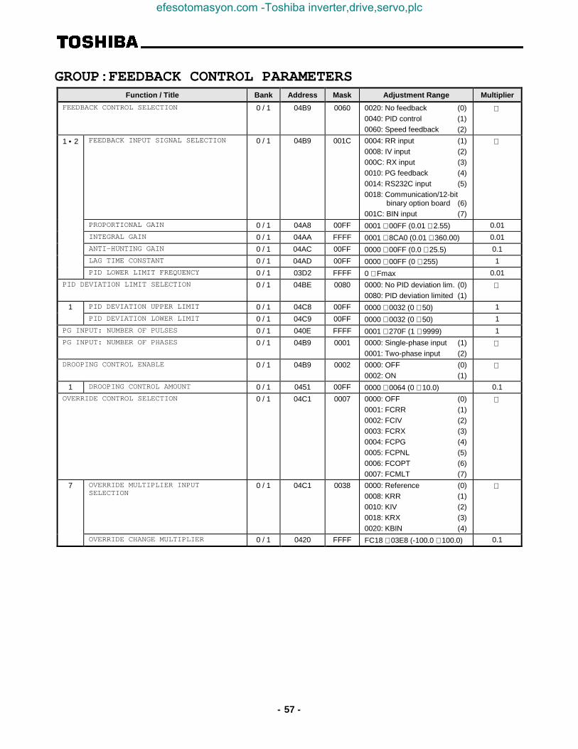
- 57 -
GROUP:FEEDBACK CONTROL PARAMETERSFunction / Title Bank Address Mask Adjustment Range Multiplier
FEEDBACK CONTROL SELECTION 0 / 1 04B9 0060 0020: No feedback (0)0040: PID control (1)0060: Speed feedback (2)
1 • 2 FEEDBACK INPUT SIGNAL SELECTION 0 / 1 04B9 001C 0004: RR input (1)0008: IV input (2)000C: RX input (3)0010: PG feedback (4)0014: RS232C input (5)0018: Communication/12-bit
binary option board (6)001C: BIN input (7)
PROPORTIONAL GAIN 0 / 1 04A8 00FF 0001 ∼ 00FF (0.01 ∼ 2.55) 0.01
INTEGRAL GAIN 0 / 1 04AA FFFF 0001 ∼ 8CA0 (0.01 ∼ 360.00) 0.01
ANTI-HUNTING GAIN 0 / 1 04AC 00FF 0000 ∼ 00FF (0.0 ∼ 25.5) 0.1
LAG TIME CONSTANT 0 / 1 04AD 00FF 0000 ∼ 00FF (0 ∼ 255) 1
PID LOWER LIMIT FREQUENCY 0 / 1 03D2 FFFF 0 ∼ Fmax 0.01
PID DEVIATION LIMIT SELECTION 0 / 1 04BE 0080 0000: No PID deviation lim. (0)0080: PID deviation limited (1)
1 PID DEVIATION UPPER LIMIT 0 / 1 04C8 00FF 0000 ∼ 0032 (0 ∼ 50) 1
PID DEVIATION LOWER LIMIT 0 / 1 04C9 00FF 0000 ∼ 0032 (0 ∼ 50) 1
PG INPUT: NUMBER OF PULSES 0 / 1 040E FFFF 0001 ∼ 270F (1 ∼ 9999) 1
PG INPUT: NUMBER OF PHASES 0 / 1 04B9 0001 0000: Single-phase input (1)0001: Two-phase input (2)
DROOPING CONTROL ENABLE 0 / 1 04B9 0002 0000: OFF (0)0002: ON (1)
1 DROOPING CONTROL AMOUNT 0 / 1 0451 00FF 0000 ∼ 0064 (0 ∼ 10.0) 0.1
OVERRIDE CONTROL SELECTION 0 / 1 04C1 0007 0000: OFF (0)0001: FCRR (1)0002: FCIV (2)0003: FCRX (3)0004: FCPG (4)0005: FCPNL (5)0006: FCOPT (6)0007: FCMLT (7)
7 OVERRIDE MULTIPLIER INPUTSELECTION
0 / 1 04C1 0038 0000: Reference (0)0008: KRR (1)0010: KIV (2)0018: KRX (3)0020: KBIN (4)
OVERRIDE CHANGE MULTIPLIER 0 / 1 0420 FFFF FC18 ∼ 03E8 (-100.0 ∼ 100.0) 0.1
efesotomasyon.com -Toshiba inverter,drive,servo,plc

- 58 -
GROUP:COMMUNICATION SETTING PARAMETERSFunction / Title Bank Address Mask Adjustment Range Multiplier
RS232 BAUD RATE 1 04AE 0018 0000: 2400 baud (0)0008: 4800 baud (1)0010: 9600 baud (2)
NUMBER OF DATA BITS 1 04AE 0040 0000: 7 bits (0)0040: 8 bits (1)
PARITY SETTING 1 04AE 0080 0000: Even parity (0)0080: Odd parity (1)
INVERTER ID NUMBER 1 04B1 00FF 0000 ∼ 00FF (0 ∼ 255) 1
COMMUNICATION SELECTION 1 04AE 0007 0000: OFF (0)0001: RS485 (1)0002: F-10, DNet, RIO (2)0003: TOSLINE S-20 (3)0004: 12 bit binary input (4)0005: 3-digit BCD (0.1Hz) (5)0006: 3-digit BCD (1Hz) (6)
1 MASTER/SLAVE SELECTION 1 04AF 0018 0000: Slave (0)0008: Master (frequency
command) (1)0010: Master (output
frequency) (2)
RS485 BAUD RATE 1 04AF 0004 0000: Normal mode (0)0004: High-speed mode (1)
2 TOSLINE-F10 COMMAND INPUT 1 04B0 0003 0000: OFF (0)0001: Frequency command (1)0002: Command input (2)0003: Both (1) and (2) (3)
TOSLINE-F10 MONITOR OUTPUT 1 04B0 003C 0000: (0) 0020: (8)0004: (1) 0024: (9)0008: (2) 0028: (10)000C: (3) 002C: (11)0010: (4) 0030: (12)0014: (5) 0034: (13)0018: (6) 0038: (14)001C: (7) 003C: (15)
TOSLINE-F10 COMM ERROR MODE 1 04B0 0080 0000: Data cleared (0)0080: Data retained (1)
3 TOSLINE-S20 RECEIVE ADDRESS 1 04CE FFFF 0000 ∼ 03FF (0 ∼ 1023) 1
TOSLINE-S20 TRANSMIT ADDRESS 1 04D0 FFFF 0000 ∼ 03FF (0 ∼ 1023) 1
TOSLINE-S20 COMMAND INPUT 1 04D2 001F 0000 ∼ 001F (0 ∼ 31) 1
TOSLINE-S20 MONITOR OUTPUT 1 04D3 001F 0000 ∼ 001F (0 ∼ 31) 1
TOSLINE-S20 FREQ REF ADDR SELECT 1 04D4 0001 0000: Disable (0)0001: Enable (1)
1
1 TOSLINE-S20 FREQ REFERENCEADDR
1 04D5 FFFF 0000 ∼ 03FF (0 ∼ 1023) 1
TOSLINE-S20 COMM ERROR MODE 1 04D4 0002 0000: Data cleared (0)0002: Data retained (1)
1
TOSLINE-S20 COMM OPTION RESET 1 02DC 0004 0000: No effect (0)0004: Reset (1)
1
RS485/12-BIT BINARY BIAS,GAIN 0 / 1 04AF 0020 0000: OFF (0)0020: ON (1)
1 RS485/12-BIT BINARY POINT #1 (Ref. 1) 0 / 1 04CA 00FF 0000 ∼ 0064 (0 ∼ 100) 1
RS485/12-BIT BINARY PT. #1 FREQ 0 / 1 04B2 FFFF 0000 ∼ Fmax (0 ∼ Fmax) 0.01
RS485/12-BIT BINARY POINT #2 (Ref. 1) 0 / 1 04CB 00FF 0000 ∼ 0064 (0 ∼ 100) 1
RS485/12-BIT BINARY PT. #2 FREQ 0 / 1 04B4 FFFF 0000 ∼ Fmax (0 ∼ Fmax) 0.01
efesotomasyon.com -Toshiba inverter,drive,servo,plc

- 59 -
(Note) All parameters in GROUP:COMMUNICATION SETTING PARAMETERS (except for RS485/12-BIT BINARY BIAS,GAIN , RS485/12-BIT BINARY POINT #1 , RS485/12-BIT BINARY PT. #1 FREQ , RS485/12-BIT BINARY POINT #2 , and RS485/12-BITBINARY PT. #2 FREQ ) must be set in the EEPROM (bank 1) to be valid. (These parameters can be set in bank 0 (RAM), but thedata settings will be written over by the values contained in the EEPROM the next time RAM is reset. Therefore, always write thedata settings for these parameters to the EEPROM (bank 1)). After changing the settings of these communication parameters, resetthe inverter to validate the data.
(Ref. 1) The data settings for parameters RS485/12-BIT BINARY POINT #1 and RS485/12-BIT BINARY POINT #2 are proportional toMAXIMUM OUTPUT FREQUENCY in GROUP:FUNDAMENTAL PARAMETERS #1.
Ex: If MAXIMUM OUTPUT FREQUENCY = 80Hz, RS485/12-BIT BINARY POINT #1 = 10%, RS485/12-BIT BINARY PT. #1FREQ = 20Hz, and an 8Hz frequency command is input, the output frequency will be 20Hz.
GROUP:AM/FM TERMINAL ADJUSTMENT PARAMSFunction / Title Bank Address Mask Adjustment Range Multiplier
FM TERMINAL FUNCTION SELECTION
(Note)
0 / 1 0484 FFFF 1194: Pre-compensationreference frequency (0)
6686: Post-compensationoutput frequency (1)
1500: Frequency setting (2)2576: Output current (3)2689: DC voltage (4)5668: Output voltage (5)3684: Torque current (6)2688: Excitation current (7)7506: PID feedback value (8)0584: Motor overload ratio (9)0586: Inv. overload ratio (10)0588: Dynamic braking resistor
OL ratio (11)835C: Input power (12)835E: Output power (13)A000: Fixed output (14)2304: Peak output current (15)8302: Peak input voltage (16)
FREQUENCY METER ADJUSTMENT 0 / 1 0486 FFFF 0000 ∼ FFFF 1
AM TERMINAL FUNCTION SELECTION (Note) 0 / 1 0488 FFFF Same as FM TERMINALFUNCTION SELECTION
CURRENT METER ADJUSTMENT 0 / 1 048A FFFF 0000 ∼ FFFF 1
efesotomasyon.com -Toshiba inverter,drive,servo,plc

- 60 -
GROUP:UTILITY PARAMETERSFunction / Title Bank Address Mask Adjustment Range Multiplier
INDUSTRIAL APPLICATIONS
(previous setting monitor for read use)
Note : If data is written to this address, the previoussetting displayed on the panel will be changed.
0 / 1 0438 00FF 0000: Std. shpmt. setting (0)0001: Pump application (1)0002: Fan application (2)0003: Conveyor application (3)0004: Hoist application (4)0005: Textiles application (5)0006: Machine tools appl. (6)
INDUSTRIAL APPLICATIONS
(for write use)
(Note , ✳)
0 / 1 04C2 00FF 0000: Does nothing (0)0011: Pump application (1)0012: Fan application (2)0013: Conveyor application (3)0014: Hoist application (4)0015: Textiles application (5)0016: Machine tools appl. (6)
STANDARD SETTING MODE SELECTION
(Note , ✳)
(Ref. 1)
0 / 1 04C2 00FF 0000: Does nothing (0)0001: 50Hz std. settings (1)0002: 60Hz std. settings (2)0003: Factory settings (3)0004: Trip clear (4)0005: Save user-set param. (5)0006: TYPE 5 reset (6)0007: Initialize typeform (7)
COMMAND MODE SELECTION 0 / 1 04B7 0007 0000: Only RS232C valid (0)0001: Terminal input valid (1)0002: Panel input valid (2)0003: Communication option
input valid (3)0004: local/remote valid (4)
FREQUENCY MODE SELECTION 0 / 1 04B7 0038 0000: Only RS232C valid (0)0008: Terminal input valid (1)0010: Panel input valid (2)0018: Comm./12-bit binary
option input valid (3)0020: local/remote valid (4)
PANEL OPERATION MODE SELECTION (Ref. 2) 0 / 1 0452 00FB 0000 ∼ 003F (0 ∼ 63)(except 0004, 0008, 000C....)
1
PASS NUMBER 0 / 1 049D 00FF 0000 ∼ 0063 (0 ∼ 99) 1
CPU VERSION 2 8000ROM VERSION 3 0000 (Monitor only) 1EEPROM VERSION 1 0380INVERTER TYPEFORM 0 05CA (Monitor only) STATUS MONITOR #1 DISPLAY SELECT 0 / 1 0454 FFFF 0001 ∼ 0010 (1 ∼ 16) 1
STATUS MONITOR #2 DISPLAY SELECT 0 / 1 0456 FFFF 0001 ∼ 0010 (1 ∼ 16) 1
STATUS MONITOR #3 DISPLAY SELECT 0 / 1 0458 FFFF 0001 ∼ 0010 (1 ∼ 16) 1
STATUS MONITOR #4 DISPLAY SELECT 0 / 1 045A FFFF 0001 ∼ 0010 (1 ∼ 16) 1
FREQUENCY UNITS SCALE FACTOR 0 / 1 0412 FFFF 0000 ∼ 4E20 (0.00 ∼ 200.00) 0.01
FREQUENCY DISPLAY RESOLUTION 0 / 1 045D 0003 0000: 1Hz (0)0001: 0.1Hz (1)0002: 0.01Hz (2)
ACC/DEC TIME UNITS SELECTION (Ref. 3) 0 / 1 045D 0004 0000: 0.1 sec. (0)0004: 0.01 sec. (1)
efesotomasyon.com -Toshiba inverter,drive,servo,plc

- 61 -
Function / Title Bank Address Mask Adjustment Range Multiplier
CURRENT UNITS SELECTION 0 / 1 045D 0008 0000: % (0)0008: A (1)
VOLTAGE UNITS SELECTION 0 / 1 045D 0010 0000: % (0)0010: V (1)
BLIND FUNCTION SELECTION 0 / 1 045E 0001 0000: Blind (0)0001: Selective unblinding (1)
1 FUNDAMENTAL PARAMS #2 BLIND 0 / 1 045E 0040 0000: Blind (0)0040: Unblind (1)
PANEL CONTROL PARAMS BLIND 0 / 1 045E 0080 0000: Blind (0)0080: Unblind (1)
TERMINAL SELECTION PARAMS BLIND 0 / 1 045F 0001 0000: Blind (0)0001: Unblind (1)
SPECIAL CONTROL PARAMS BLIND 0 / 1 045F 0002 0000: Blind (0)0002: Unblind (1)
FREQUENCY SETTING PARAMS BLIND 0 / 1 045F 0004 0000: Blind (0)0004: Unblind (1)
PROTECTION FUNCTION PARAMS BLIND 0 / 1 045F 0008 0000: Blind (0)0008: Unblind (1)
PATTERN RUN CONTROL PARAMS BLIND 0 / 1 045F 0010 0000: Blind (0)0010: Unblind (1)
FEEDBACK CONTROL PARAMS BLIND 0 / 1 045F 0020 0000: Blind (0)0020: Unblind (1)
COMMUNICATION PARAMS BLIND 0 / 1 045F 0040 0000: Blind (0)0040: Unblind (1)
INDUSTRIAL APPL:PUMP PARAMS BLIND 0 / 1 045F 0080 0000: Blind (0)0080: Unblind (1)
INDUSTRIAL APPL:FAN PARAMS BLIND 0 / 1 0460 0001 0000: Blind (0)0001: Unblind (1)
INDUSTRIAL APPL: CONVEYOR BLIND 0 / 1 0460 0002 0000: Blind (0)0002: Unblind (1)
INDUSTRIAL APPL: HOIST BLIND 0 / 1 0460 0004 0000: Blind (0)0004: Unblind (1)
INDUSTRIAL APPL: TEXTILES BLIND 0 / 1 0460 0008 0000: Blind (0)0008: Unblind (1)
INDUST APPL:MACHINE TOOLS BLIND 0 / 1 0460 0010 0000: Blind (0)0010: Unblind (1)
AM/FM ADJUSTMENT PARAMS BLIND 0 / 1 0461 0001 0000: Blind (0)0001: Unblind (1)
MOTOR PARAMETERS BLIND 0 / 1 0461 0004 0000: Blind (0)0004: Unblind (1)
(Ref. 1): The data setting value will be retained in the EEPROM even if it was written to RAM (bank 0).Note ) If 0000 (does nothing) is written to the EEPROM, the previous setting monitor value willbecome 0. Also, if the industrial application parameters selection is written to after writing to thestandard setting mode selection, the standard setting mode selection’s previous data setting will becleared.
(Ref. 2): If the setting value is written to RAM only, the value displayed on the panel will not change. Also,when the setting value is written to EEPROM, the value displayed on the panel will not change until areset is performed.
(Ref. 3): If the setting of ACC/DEC TIME UNITS SELECTION is changed after setting the ACC/DEC times,the ACC/DEC times will become 10 times or 0.1 times their former value. Therefore, always resetthe ACC/DEC time settings after changing the setting of ACC/DEC TIME UNITS SELECTION .
efesotomasyon.com -Toshiba inverter,drive,servo,plc

- 62 -
GROUP:MOTOR RATING PARAMETERSFunction / Title Bank Address Mask Adjustment Range Multiplier
NUMBER OF MOTOR POLES 0 / 1 04C3 00FF 0001: (2)0002: (4)0003: (6)0004: (8)0005: (10)0006: (12)0007: (14)0008: (16)
2
MOTOR RATED CAPACITY 0 / 1 041E FFFF 0001 ∼ 270F (0.1 ∼ 999.9) 0.1
MOTOR TYPE 0 / 1 04BF 0030 0000:Toshiba EQPIII motor (0)0010:Toshiba STD motor (1)0020:Other (2)
2 MOTOR RATED VOLTAGE(230 / 460v units) 0 / 1 04C6 00FF 0012 ∼ 0078 (90 ∼ 600) 5
(575v units) 042C 001A ∼ 00AC (130 ∼ 860)MOTOR RATED FREQUENCY 0 / 1 04C7 00FF 0000 ∼ 00C8 (0 ∼ 400) 2
MOTOR RATED RPM 0 / 1 040C FFFF 0000 ∼ 270F (0 ∼ 9999) 1
AUTO-TUNING ENABLE 0 04BE 0008 0000: Auto-tuning disabled (0)0008: Auto-tuning enabled (1)
LOAD MOMENT OF INERTIA 0 / 1 04BF 00C0 0000: Small (0)0040: Medium (1)0080: Large (2)00C0: Very large (3)
efesotomasyon.com -Toshiba inverter,drive,servo,plc

- 63 -
8.5 ASCII Character Codes
0 1 2 3 4 5 6 70 NUL DLE SP 0 @ P ` p1 SOH DC1 ! 1 A Q a q2 STX DC2 “ 2 B R b r3 ETX DC3 # 3 C S c s4 EOT DC4 $ 4 D T d t5 ENQ NAK % 5 E U e u6 ACK SYN & 6 F V f v7 BEL ETB ‘ 7 G W g w8 BS CAN ( 8 H X h x9 HT EM ) 9 I Y i yA LF SUB * : J Z j zB VT ESC + ; K [ k {C FF FS , < L \ l |D CR GS - = M ] m }E SO RS . > N ^ n ~F SI US / ? O _ o DEL
Note: Shaded items in the above table indicate valid RS232 communication codes.
efesotomasyon.com -Toshiba inverter,drive,servo,plc

- 64 -
8.6 Notes
efesotomasyon.com -Toshiba inverter,drive,servo,plc

TOSHIBA INTERNATIONAL CORPORATION
INDUSTRIAL DIVISION13131 West Little York Rd., Houston, TX 77041Tel: [800] 231-1412 Fax: [713] 466-8773 Telex: 762078
Printed in U.S.A
efesotomasyon.com -Toshiba inverter,drive,servo,plc